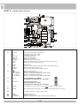
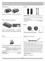
1
T2 f w.09 QUADRO ELETTRONICO PER IL COMANDO DI UNO O DUE MOTORI MONOFASI COFFRET ELECTRONIQUE POUR LE CONTRÔLE DE UN OU DEUX MOTEURS MONOPHASE ELECTRONIC PANEL FOR THE CONTROL OF ONE OR TWO SINGLE PHASE MOTORS ELEKTRONISCHE STEUERUNG FÜR EIN ODER ZWEI EINPHASENMOTOREN CUADRO ELECTRÓNICO DE MANDO PARA UNO O DOS MOTORES MONOFÁSICOS NUOVA VERSIONE con funzionamento a uomo presente se le fotocellule o le coste sono guaste. Conforme alle normative in vigore. NOUVELLE VERSION avec travail avec homme present, dans le cas de panne de sécurité. Conforme aux Normes en vigueur. NEW VERSION with functioning in dead man mode when the safety devices are failing. According to current European Norms. NEUE VERSION mit arbeit im mannsbeisein im fall eines ausfalls der Sicherheiten. In Übereinstimmung mit der aktuellen Normen. NUEVA VERSIÓN con funcionamiento a hombre presente en caso de averías con los accesorios de seguridad. En conformidad a las Normas en vigor. Ora con comando pedonale via radio! Maintenant, avec commande via radio pour l’ouverture piétonnière! Now with pedestrian radio control! Jetzt mit Steuerung der Fußgängeröffnung über Funk! ¡Ahora con mando de apertura peatonal vía radio! ITALIANO pag. 05 / FRANÇAIS pag. 12 / ENGLISH page 19 / DEUTSCH pag. 26 / ESPAÑOL pag. 33 F ISTRUZIONI DI SICUREZZA IMPORTANTI PER L’INSTALLAZIONE INSTRUCTIONS DE SECURITE IMPORTANTES POUR L’INSTALLATION - ATTENZIONE PER LA SICUREZZA DELLE PERSONE É IMPORTANTE CHE VENGANO SEGUITE TUTTE LE ISTRUZIONI - ATTENTION POUR LA SECURITE DES PERSONNES IL EST IMPORTANT QUE TOUTES LES INSTRUCTIONS SOIENT SUIVIES SEGUIRE TUTTE LE ISTRUZIONI DI INSTALLAZIONE SUIVRE TOUTES LES INSTRUCTIONS D’INSTALLATION 1° - Questo libretto d’istruzioni è rivolto esclusivamente a del personale specializzato che sia a conoscenza dei criteri costruttivi e dei dispositivi di protezione contro gli infortuni per i cancelli, le porte e i portoni motorizzati (attenersi alle norme e alle leggi vigenti). 2° - L’installatore dovrà rilasciare all’utente finale un libretto di istruzioni in accordo alla EN 12635. 3° - L’installatore prima di procedere con l’installazione deve prevedere l’analisi dei rischi della chiusura automatizzata finale e la messa in sicurezza dei punti pericolosi identificati (seguendo le norme EN 12453/EN 12445). 4° - Il cablaggio dei vari componenti elettrici esterni all’operatore (ad esempio fotocellule, lampeggianti, ecc.) deve essere effettuato secondo la EN 60204-1 e le modifiche a questa apportate dal punto 5.2.2 della EN 12453. 5° - L’eventuale montaggio di una pulsantiera per il comando manuale del movimento deve essere fatto posizionando la pulsantiera in modo che chi la aziona non si trovi in posizione pericolosa; inoltre si dovrà fare in modo che sia ridotto il rischio di azionamento accidentale dei pulsanti. 6° - Tenete i comandi dell’automatismo (pulsantiera, telecomando etc.) fuori dalla portata dei bambini. I comandi devono essere posti ad un’altezza minima di 1,5 m dal suolo e fuori dal raggio d’azione delle parti mobili. 7° - Prima di eseguire qualsiasi operazione di installazione, regolazione, manutenzione dell’impianto, togliere la tensione agendo sull’apposito interruttore magnetotermico collegato a monte dello stesso. 1° - Ce livret d’instructions est adressé exclusivement à un personnel spécialisé qui connaît les critères de construction et les dispositifs de protection contre les accidents concernant les portails, les portes et les grandes portes motorisés (s’en tenir aux normes et aux lois en vigueur). 2° - L’installateur devra délivrer à l’utilisateur final un livret d’instruction en accord à la EN 12635. 3° - L’installateur avant de procéder à l’installation, doit prévoir l’analyse des risques de la fermeture automatisée finale et la mise en sécurité des points identifiés dangereux (en suivant les normes EN 12453/EN 12445). 4° - Le câblage des divers composants électriques externes à l’opérateur (par exemple photocellules, clignotants, etc) doit être effectué selon la EN 60204-1 et les modifications apportées à celle-ci dans le point 5.2.2 de la EN 12453. 5° - Le montage éventuel d’un tableau pour la commande manuelle du mouvement doit être fait en positionnant le tableau de façon à ce que la personne qui l’actionne ne se trouve pas en position de danger; de plus, il faudra faire en sorte que le risque d’actionnement accidentel des boutons soit réduit. 6° - Tenir les commandes de l’automatisme (tableau, télécommande, etc) hors de portée des enfants. Les commandes doivent être placées à une hauteur minimum de 1,5 m du sol et hors du rayon d’action des parties mobiles. 7° - Avant l’exécution de toute opération d’installation, de réglage, d’entretien de l’installation, couper le courant en agissant sur l’interrupteur magnétothermique à cet effet, branché en amont de l’installation. LA DITTA RIB NON ACCETTA NESSUNA RESPONSABILITÀ per eventuali danni provocati dalla mancata osservanza nell’installazione delle norme di sicurezza e delle leggi attualmente in vigore. LA SOCIETE RIB N’ACCEPTE AUCUNE RESPONSABILITE pour d’éventuels dommages provoqués par la non-observation dans l’installation, des normes de sécurité et des lois actuellement en vigueur. CONSERVARE CON CURA QUESTE ISTRUZIONI CONSERVER SOIGNEUSEMENT CES INSTRUCTIONS 1° - S e non é previsto nella centralina elettrica, installare a monte della medesima un’interruttore di tipo magnetotermico (onnipolare con apertura minima dei contatti pari a 3mm) che riporti un marchio di conformità alle normative internazionali. Tale dispositivo deve essere protetto contro la richiusura accidentale (ad esempio installandolo dentro quadro chiuso a chiave). 2° - Per la sezione ed il tipo dei cavi RIB consiglia di utilizzare un cavo di tipo H05RN-F con sezione minima di 1,5mm2 e comunque di attenersi alla norma IEC 364 e alle norme di installazione vigenti nel proprio Paese. 3° - Posizionamento di un’eventuale coppia di fotocellule: Il raggio delle fotocellule deve essere ad un’altezza non superiore a 70 cm dal suolo e ad una distanza dal piano di movimento dell’anta non superiore a 20 cm. Il loro corretto funzionamento deve essere verificato a fine installazione in accordo al punto 7.2.1 della EN 12445. 4° - Per il soddisfacimento dei limiti imposti dalla EN 12453, se la forza di picco supera il limite normativo di 400 N è necessario ricorrere alla rilevazione di presenza attiva sull’intera altezza del cancello (fino a 2,5 m max) - Le fotocellule in questo caso sono da applicare all’esterno tra le colonne ed all’interno per tutta la corsa della parte mobile ogni 60÷70 cm per tutta l’altezza delle colonne del cancello fino ad un massimo di 2,5 m (EN 12445 punto 7.3.2.1) - es. colonne alte 2,2 m => 6 coppie di fotocellule - 3 interne e 3 esterne (meglio se dotate di sincronismo - 6 FIT SYNCRO con 2 TX SYNCRO). 1° - S i la centrale électrique ne dispose d’aucun interrupteur, il faut en installer un de type magnétothermique en amont de cette dernière (omnipolaire avec ouverture minimale des contacts correspondant à 3mm); la marque de cet interrupteur devra être en conformité avec les normes internationales. Ce dispositif doit être protégé contre toute remise en fonction accidentelle (ex. en l’installant dans un coffre fermant à clé). 2° - En ce qui concerne la section et le type des câbles, le conseil de RIB est celui d’utiliser un câble de type H05RN-F présentant une section minimale de 1,5mm2 et, quoi qu’il en soit, de se conformer à la norme IEC 364, ainsi qu’aux normes d’installation en vigueur dans le pays de destination. 3° - Positionnement d’un éventuel jeu de photocellules : le faisceau des photocellules ne doit pas être à une hauteur supérieure à 70 cm du sol et 20 cm du bord du vantail. Leur correct effectivité fonctionnement doit être vérifié terminant l’installation, selon le point de la 7.2.1 de la EN 12445. 4° - Afin de satisfaire aux limites imposées par la norme EN 12453, si la force d’impact dépasse la limite de 400N, il sera nécessaire de détecter une présence sur la hauteur totale du portail (jusqu’à un maximum de 2,5 m) - Les cellules photo-électriques dans ce casci doivent être s’appliquent extérieurement entre les colums et intérieurement pour toute la course de la pièce de mobil chaque 60÷70 cm pour toute la taille de la colonne de la porte jusqu’à un maximum de 2,5 m (EN 12445 point 7.3.2.1) - exemple: taille 2,2m de colonne = > 6 copies des cellules photo-électriques - 3 internes et 3 externes (meilleur si complet du dispositif de syncronism - FIT SYNCRO avec TX SYNCRO). N.B.:É obbligatoria la messa a terra dell’impianto I dati descritti nel presente manuale sono puramente indicativi. RIB si riserva di modificarli in qualsiasi momento. Realizzare l’impianto in ottemperanza alle norme ed alle leggi vigenti. N.B.:La mise à terre de l’installation est obligatoire. Les données figurant dans le présent manuel sont fournies à titre purement indicatif. RIB se réserve le droit de les modifier à tout moment, sans aucun préavis. Effectuer l’installation en conformité avec les normes et les lois en vigueur. 2 G B ANLEITUNGEN FÜR D WICHTIGE SICHERHEITS DIE INSTALLATIONEN IMPORTANT SAFETY INSTRUCTIONS FOR THE INSTALLATION - ATTENTION FOR THE SAFETY OF THE PEOPLE IT IS IMPORTANT TO FOLLOW ALL THE INSTRUCTIONS. - ACHTUNG FÜR DIE SICHERHEIT DER PERSONEN IST ES WICHTIG, DASS ALLE ANWEISUNGEN GENAU AUSGEFÜHRT WERDEN ALLE INSTALLATIONSANLEITUNGEN BEFOLGEN FOLLOW ALL INSTALLATION INSTRUCTIONS 1° - D iese Betriebsanleitung dient ausschließlich dem Fachpersonal, welche die Konstruktionskriterien und die Sicherheits-Vorschriften gegen Unfälle für Tore, Türen und automatische Tore kennt (geltende Normen und Gesetze beachten und befolgen). 2° - Der Monteur muss dem Endkunde eine Betriebsanleitung in Übereinkunft der EN12635 überreichen. 3° - Vor der Installierung muss für die automatische Schließung und zur Sicherheitsgewährung der identifizierten kritischen Punkte, eine Risiko Analyse vorgenommen werden mit der entsprechenden Behebung der identifizierten, gefährlichen Punkte. (die Normen EN 12453/EN 12445 befolgend). 4° - Die Verkabelung der verschiedenen externen elektrischen Komponenten zum Operator (z.B. Fotozellen, Blinker etc.) muss nach EN 60204-1 ausgeführt werden, Änderungen davon nach Punkt 5.2.2 der EN 12453. 5° - Die eventuelle Montage einer Schalttafel für den manuellen Bewegungsbefehl muss so angebracht werden, dass der Benutzer sich nicht in einer Gefahrenzone befindet, und dass, das Risiko einer zufälligen nicht gewollten Aktivierung von Schaltern gering ist. 6° - Alle Steuerungselemente (Schalttafel, Fernbedienung etc.) gehören nicht in Reichweite von Kindern. Die Kommandos müssen min. 1,5 m ab Boden und außerhalb des Aktionsbereiches der mobilen Teile angebracht werden. 7° - Vor jeglichem Eingriff, sei es Installation, Regulation oder Wartung der Anlage, muss vorher die Stromzufuhr unterbrochen werden, den dafür bestimmten Magnetthermo-Schalter drücken, der am Eingang der Anlage installiert ist. 1° - This handbook is exclusively addressed to the specialized personnel who knows the constructive criteria and the protection devices against the accidents for motorized gates, doors and main doors (follow the standards and the laws in force). 2° - The installer will have to issue to the final user a handbook in accordance with the EN 12635. 3° - Before proceeding with the installation, the installer must forecast the risks analysis of the final automatized closing and the safety of the identified dangerous points (following the standards EN 12453/EN 12445). 4° - The wiring harness of the different electric components external to the operator (for example photoelectric cells, flashlights etc.) must be carried out according to the EN 60204-1 and the modifications to it done in the point 5.2.2 of the EN 12453. 5° - The possible assembly of a keyboard for the manual control of the movement must be done by positioning the keyboard so that the person operating it does not find himself in a dangerous position; moreover, the risk of accidental activation of the buttons must be reduced. 6° - Keep the automatism controls (push-button panel, remote control etc.) out of the children way. The controls must be placed at a minimum height of 1,5 m from the ground and outside the range of the mobile parts. 7° - Before carrying out any installation, regulation or maintenance operation of the system, take off the voltage by operating on the special magnetothermic switch connected upstream it. THE RIB COMPANY DOES NOT ACCEPT ANY RESPONSIBILITY for possible damages caused by the non observance during the installation of the safety standards and of the laws in force at present. DIE FIRMA RIB ÜBERNIMMT KEINE VERANTWORTUNG für eventuelle Schäden, die entstehen können, wenn die Installierungsvorschriften die den gültigen Sicherheitsnormen entsprechen, nicht eingehalten werden. KEEP THESE INSTRUCTIONS WITH CARE INSTALLATIONSVORSCHRIFTEN BEACHTET WERDEN 1° - Install a thermal magnetic switch (omnipolar, with a minimum contact opening of 3 mm) before the control board, in case this is not provided with it. The switch shall be guaranteed by a mark of compliance with international standards. Such a device must be protected against accidental closing (e.g. Installing it inside the control panel key locked container). 2° - As far as the cable section and the cable kind are concerned, RIB suggests to use an H05RN-F cable, with a minimum section of 1,5mm2, and to follow, In any case, the IEC 364 standard and Installation regulations In force In your Country. 3° - Positioning of an eventual pair of photocells: The beam of the photocells must be at an height not above the 70 cm from the ground, and, should not be more than 20 cm away from the axis of operation of the gate (Sliding track for sliding gate or door, and the hinges for the swing gate). In accordance with the point 7.2.1 of EN 12445 their correct functioning must be checked once the whole installation has been completed. 4° - In order to comply with the limits defined by the EN 12453 norm, if the peak force is higher than the limit of 400N set by the norm, it is necessary to use an active obstacle detection system on the whole height of the gate (up to a maximum of 2,5 m) - The photocells in this case must be apply externally between the colums and internally for all the race of the mobil part every 60÷70 cm for all the height of the column of the gate up to a maximum of 2,5 m (EN 12445 point 7.3.2.1). example: column height 2,2 m => 6 copies of photocells - 3 internal and 3 external (better if complete of syncronism feature - FIT SYNCRO with TX SYNCRO). 1° - W enn nicht bereits an der elektrischen Schaltzentrale vorgesehen, muss vor der Schaltzentrale ein thermomagnetischer Schalter installiert werden (omnipolar, mit einer minimalen Kontaktöffnung von 3 mm), der ein von den internationalen Normen anerkanntes Konformitätszeichen besitzt. Solch ein Geraet muss vor Vandalismus geschuetzt werden(z.B.mit einen Schluesselkatsten in einem Panzergehaeuse) 2° - RIB empfiehlt den Kabeltyp H05RN-F mit einem minimalen Querschnitt von 1,5mm2 generell sollten die Normative IEC 364 und alle anderen geltenden Montagenormen des Bestimmungslandes eingehalten werden. 3°- Position des ersten paar Fotozellen: Der sollten nicht hoeher als 70cm vom Boden sein, und sollte nicht mehr als 20 cm entfernt von der Achse des Tores sitzen (das gilt fuer Schiebe und Drehtore). In Übereinstimmung mit dem Punkt 7.2.1 der EN 12445 Norm, ihr korrektes Funktionieren muß einmal überprüft werden. 4°- In Einklang mit der Norm EN12453, ist es bei Toren notwendig eine komplette Sicherheitslieiste zu installieren, bei denen mehr als 400N Kraft aufgewand werden muessen, um das Tor zum anhalten zu bringen (Maximum von 2,5 m anwenden) Die Fotozellen müssen in diesem Fall sein beantragen außen zwischen den colums und innerlich das ganzes Rennen des mobil Teils jede 60÷70cm für die ganze Höhe der Spalte des Gatters bis zu einem Maximum von 2,5 m - EN 12445 Punkt 7.3.2.1). Beispiel: Spalte Höhe 2,2 m => 6 Kopien von Fotozellen - 3 intern und 3 extern (besser, wenn komplett von der syncronism Eigenschaft FIT SYNCRO mit TX SYNCRO). ANMERKUNG: Die Erdung der Anlage ist obligatorisch Die in diesem Handbuch aufgeführten Daten sind ausschließlich empfohlene Werte. RIB behält sich das Recht vor, das Produkt zu jedem Zeitpunkt zu modifizieren. Die Anlage muss in Übereinstimmung mit den gültigen Normen und Gesetzen montiert werden. N.B.: The system must be grounded Data described by this manual are only Indicative and RIB reserves to modify them at any time. Install the system complying with current standards and regulations. 3 E S IMPORTANTES INSTRUCCIONES DE SEGURIDAD PARA LA INSTALACIÓN - CUIDADO UNA INCORRECTA INSTALACIÓN PUEDE CAUSAR GRAVES DAÑOS SEGUIR TODAS LAS INSTRUCCIONES DE INSTALACIÓN 1° - E ste manual de instrucciones está exclusivamente dirigido a personal especializado que conozca los criterios de construcción y de los dispositivos de protección contra accidentes con cancelas, puertas y portales motorizados (atenerse a las normas y a las leyes vigentes). 2° - El instalador tendrá que dar al utilizador final un manual de instrucciones de acuerdo con la EN 12635. 3° - El instalador antes de proceder con la instalación tiene que hacer una analisis de los riesgos del cierre automatizado final y la puesta en seguridad de los puntos identificados como peligrosos (siguiendo las normas EN 12453 / EN 12445). 4° - El cablaje de los varios componentes eléctricos externos al operador (por ejemplo fotocélulas, los intermitentes, etc) tiene que ser efectuado según la EN 60204-1 y a las modificas sucesivas aportadas por el punto 5.2.2 della EN 12453. 5° - El eventual montaje de un panel de mandos para la gestión del movimiento manual tiene que ser efectuado posicionando el panel en modo que quién lo accione no se encuentre en una posición peligrosa; además se tiene que hacer en modo que el riesgo de accionamiento accidental de los pulsadores sea mínimo. 6° -Tener los mandos del automatismo (panel de mandos, mando a distancia, etc.) lejos del alcance de los niños. Los mandos tienen que ser puestoa una altura mínima de 1,5 m del suelo y fuera del radio de acción de las partes móviles. 7° - Antes de ejecutar cualquier operación de instalación, ajuste o mantenimiento del sistema, quitar la corriente accionando el respectivo interruptor magnetotérmico conectado antes del mismo. LA EMPRESA RIB NO ES RESPONSABLE por eventuales daños provocados por la falta de respeto de las normas de seguridad, durante la instalación y de las leyes actualmente vigentes. CONSERVAR CUIDADOSAMENTE ESTAS INSTRUCCIONES 1° - E n el caso de que no sea previsto en la central eléctrica, instalar antes de la misma, un interruptor de tipo magnetotérmico (omnipolar con una abertura mínima de los contactos de 3 mm) que dé un sello de conformidad con las normas internacionales. Este dispositivo tiene que estar protegido contra cierres accidentales (por ejemplo instalándolo dentro de un panel cerrado a llave). 2° - Para la sección y el tipo de los cables, RIB aconseja utilizar cables de tipo H05RN-F con sección mínima de 1,5mm2 e igualmente atenerse a la norma IEC 364 y a las normas de instalación del propio País. 3° - Posicionamiento eventual de un par de fotocélulas. El rayo de las fotocélulas no debe estar a más de 70 cm de altura desde el suelo y a una distancia de la superficie de movimiento de la puerta, no superior a 20 cm. El correcto funcionamiento tiene que ser controlado al final de la instalación de acuerdo con el punto 7.2.1 de la EN 12445. 4° - Para satisfascer los límites impuestos por la EN 12453, si la fuerza de punta supera el límite normativo de 400 N, es necesario recurrir al control de presencia activa en toda la altura de la puerta (hasta a 2,5 m max). Las fotocélulas en este caso se tienen que colocar en el exterior entre las columnas y en el interior por todo el recorrido de la parte móvil cada 60÷70 cm en toda la altura de las columnas de la cancela hasta un máximo de 2,5 m (EN 12445 punto 7.3.2.1) - es. columnas altas de 2,2 m => 6 par de fotocélulas - 3 internas y 3 externas (mejor si están provistas de sincronismo - 6 FIT SYNCRO con 2 TX SYNCRO). PS.: Es obligatorio la puesta a tierra del sistema. Los datos descritos en el presente manual son sólamente indicativos. RIB se reserva de modificarlos en cualquier momento. Realizar el sistema respetando las normas y las leyes vigentes. 4 T2 cod. BC07086 T2 CRX cod. BC07085 COLLEGAMENTI ELETTRICI LAMPEGGIATORE ANTENNA CALZA ANTENNA R=2,2KΩ SPIA + BUZZER - 12 Vdc per AUTOTEST PER COSTA 12 Vdc per ACCESSORI + + - FOTOCELLULE ALIMENTAZIONE 230Vac 50 Hz COSTE + PASSO PASSO PEDONALE COMUNE SERRATURA ELETTRICA 5 MOTOR 2 CONDENSATORE M2 MOTOR 1 CONDENSATORE M1 I I A - CONNESSIONI ON JP17 TR2 TR1 S3 J8 J5 JP1 JP2 J4 JP3 J6 J1 J3 J7 J2 J1 N -L1 Alimentazione 230 Vac 50/60 Hz (120V/60Hz a richiesta) J2 D+ TEST D+ D - PHOT. NC EDGE NC K BUTT. PED. BUTT. COM LOCK Positivo per alimentazione autotest costa a 12Vdc Positivo per alimentazione accessori a 12Vdc Negativo per alimentazione accessori a 12Vdc Contatto fotocellule (NC) Contatto Costa (NC) Contatto impulso singolo (NA) Contatto comando apertura pedonale (NA) Comune dei contatti Collegamento elettroserratura (MAX 15W 12V) J3 AERIAL COM BUZZER SIGNAL Antenna radio Comune dei contatti Collegamento segnalatore sonoro (12Vdc max 200 mA) Spia cancello aperto 12Vdc U - MOTOR 2 V-W - MOTOR 2 U - MOTOR 1 V-W - MOTOR 1 Lampeggiatore (max 40W ) COLLEGAMENTO COMUNE MOTORE 2 COLLEGAMENTO INVERTITORI E CONDENSATORE MOTORE 2 COLLEGAMENTO COMUNE MOTORE 1 COLLEGAMENTO INVERTITORI E CONDENSATORE MOTORE 1 J4 J5 SW T2 NON TOCCARE IL PONTICELLO ! SE VIENE RIMOSSO L’OPERATORE NON FUNZIONA! J6 SW RADIO ( solo per modelli CRX) NON TOCCARE IL PONTICELLO ! SE VIENE RIMOSSO IL SISTEMA RADIO NON FUNZIONA! J7 PROBE Morsettiera per il collegamento alla sonda riscaldatore incorporata solo per motoriduttore King Ice (cod. AA14019) J8 RADIO Modulo radio incorporato (modello CRX), o connettore per radio ricevitore RIB ad innesto con alimentazione a 12 Vdc. Selezione funzionamento con 1 o 2 motori JP17 S3 TR1 TR2 PROG TORQUE LOW SPEED Pulsante per la programmazione Regolatore elettronico della forza Regolatore elettronico della velocità lenta in accostamento con DIP 7 ON (vedi tab. 1) 6 I B - MICROINTERRUTTORI DI GESTIONE TABELLA 1 1 2 3 4 5 6 7 8 DIP 1 ON) - CONTROLLO SENSO DI ROTAZIONE DEL/ DEI MOTORE/I (PUNTO C) DIP 2 (ON) - PROGRAMMAZIONE TEMPI (PUNTO D) DIP 1-2MEMORIZZAZIONE/CANCELLAZIONE CODICI RADIO COMANDO APERTURA TOTALE (DIP 1 ON seguito da DIP 2 ON) (PUNTO E) SOLO PER MODELLI CRX DIP 1-3M EMORIZZAZIONE/CANCELLAZIONE CODICI RADIO COMANDO APERTURA PEDONALE (DIP 1 ON seguito da DIP 3 ON) (PUNTO F) SOLO PER MODELLI CRX DIP 2-1PROGRAMMAZIONE TEMPI APERTURA PEDONALE (PUNTO D) DIP 3Tempo di attesa prima della chiusura automatica totale e pedonale(ON) DIP 4Fotocellule sempre attive (OFF) - Fotocellule attive solo in chiusura (ON) DIP 5 Prelampeggio (ON) - Lampeggio normale (OFF) DIP 6Comando impulso singolo (K BUTT) e Ricevitore radio passo passo (OFF) - automatico (ON) DIP 7 Rallentamento (ON - attivato) DIP 8 Abilitazione serratura elettrica (ON-attivato) DIP 9Abilitazione colpo di sgancio serratura elettrica e facilitazione sblocco (ON - attivata) DIP 10 Abilitazione colpo di aggancio serratura elettrica (ON - attivato) DIP 11 Se OFF la funzione black out non é attiva Se ON la funzione black out é attiva (vedi TAB 2 pag. 10) DIP 12 Gestione richiusura immediata dopo il transito da fotocellule ON - Abilitata OFF- Disabilitata DIP 13Abilitazione TEST monitoraggio costa (ON abilitato, OFF disabilitato) DIP 14 Selezione tipologia di motore collegato (vedi tabella 1 a lato) DIP 15 Selezione tipologia di motore collegato (vedi tabella 1 a lato) DIP 16 Selezione tipologia di motore collegato (vedi tabella 1 a lato) JP 17Selezione funzionamento con 1 o 2 motori (di default jumper chiuso 2 motori) JP1 => Verificare che il ponticello sia inserito! JP2 => Verificare che il ponticello sia inserito! JP3 => Verificare che il ponticello sia inserito! TIPOLOGIA DI MOTORE KING 230/50 KING L 230/50 KING 220/60 KING L 220/60 KING ICE 230/50 MAGIC IRR. 105° MAGIC IRR. 180° MAGIC REV. 105° MAGIC REV. 180° DUKE 110° DUKE 180° PRATIC PRINCE REV IDRO 27/1B IDRO 27/R IDRO 27 SUPER/R IDRO 27 SUPER/1B FLUID R DVI FLUID R SVI FLUID 2B DVI FLUID 2B SVI IDRO 39/R IDRO 39/1B IDRO 39/2B KING FAST 230/50 KING 120/60 KING L 120/60 R50 IDRO C 27/1B IDRO C 27/2B IDRO C 27/R FUSIBILI F1 T100mA F2 5A CODICE AA14001 AA14010 AA14002 AA14011 AA14019 AA10960 AA10965 AA10920 AA10930 AA10975 AA10985 AA18001 AA14045 AA10863 AA10860 AA10867 AA10879 AA10899 AA10901 AA10897 AA10898 AA10871 AA10876 AA10881 AA14008 AA14003 AA14012 AA21580 AA10884 AA10882 AA10883 DIP 14 OFF DIP 15 OFF DIP 16 OFF ON OFF OFF OFF ON ON ON OFF OFF OFF OFF ON ON OFF ON OFF ON ON ON ON ON Fusibile di protezione accessori Fusibile di protezione motori C - CONTROLLO SENSO DI ROTAZIONE DEI MOTORI TORQUE TR1 - REGOLATORE ELETTRONICO DELLA FORZA La regolazione della forza viene fatta ruotando il Trimmer TORQUE che serve a variare la tensione di uscita ai capi del motore (ruotando in senso orario si da più forza al motore). Tale forza si include automaticamente dopo 3 secondi dall’inizio di ogni manovra. Questo per dare il massimo di spunto al motore al momento della partenza. NOTA: SE QUESTO TRIMMER VIENE REGOLATO DOPO AVERE ESEGUITO LA PROCEDURA DI PROGRAMMAZIONE, È POSSIBILE CHE LA MISURA DI INIZIO RALLENTAMENTO SUBISCA DELLE VARIAZIONI (IN PIU’ O IN MENO RISPETTO ALLA PRECEDENTE), PERTANTO SE SI ESEGUE UNA NUOVA REGOLAZIONE DEL TRIMMER, SI CONSIGLIA DI RIESEGUIRE LA PROGRAMMAZIONE DEI TEMPI. Questo controllo ha il compito di agevolare l’installatore durante la messa in opera dell’impianto, o per eventuali controlli successivi. 1 - Posizionare il cancello a metà corsa utilizzando lo sblocco manuale. 2 - Mettere il DIP1 in posizione ON => il led rosso DL1 inizia a lampeggiare. 3 - Premere e mantenere premuto il pulsante PROG => I LED VERDI DL3 e DL5 si accendono e il cancello si dovrà aprire con sfasamento fisso delle ante di due secondi (il movimento é eseguito ad uomo presente, apre-chiude-apre-etc...). Verificare il movimento delle ante e regolare la posizione dei finecorsa meccanici di apertura. Se uno dei due o tutti e due i motori chiudono invece di aprire, rilasciare il pulsante PROG ed invertire i due invertitori (V1/2 e W1/2) del/i motore/i interessato/i. 4 - Premere il pulsante PROG e mantenerlo premuto per CHIUDERE completamente il cancello - Quando si accendono i LED rossi DL4 e DL6, le ante stanno chiudendo (con uno sfasamento di 4 secondi). Verificare il movimento delle ante e regolare la posizione dei finecorsa meccanici di chiusura. 5 - Dopo 3 sec. e fino a 10 sec. di movimento in apertura o in chiusura, si innesca automaticamente la forza elettronica regolabile agendo sul trimmer TORQUE (girare il trimmer in senso orario per dare maggior forza). 6 - Dopo 10 secondi di lavoro i motori rallentano (se DIP 7 su ON). Regolate il rallentamento dei motori in accostamento agendo sul trimmer LOW SPEED. 7 - Chiudere completamente il cancello. 8 - Spostare il DIP 1 su OFF. Il led rosso DL1 si spegnerà. N.B.: Durante questo controllo le fotocellule e le coste non sono attive. In questa modalità il radiocomando non può funzionare. RALLENTAMENTO - LOW SPEED TR2 ATTENZIONE: I MOTORI IDRAULICI NON HANNO LA POSSIBILITA’ DI USUFRUIRE DELLA MODALITA’ DI RALLENTAMENTO ANCHE SE IL DIP 7 E’ IN POSIZIONE ON (VEDI TAB 1 PUNTI 4-5-8). La regolazione della velocità lenta viene eseguita agendo sul Trimmer LOW SPEED tramite il quale si varia la tensione di uscita ai capi del/dei motore/i (ruotandolo in senso orario si aumenta la velocità). La regolazione viene eseguita per determinare la corretta velocità di fine apertura e fine chiusura in base alla struttura del cancello o in presenza di leggeri attriti che potrebbero compromettere il corretto funzionamento del sistema. Il rallentamento viene determinato automaticamente dal quadro elettronico in fase di programmazione tempi, e viene attivato a circa 50÷60 cm prima del raggiungimento del finecorsa meccanico di apertura o di chiusura. SEGNALAZIONI LED DL1 - (Rosso) - Programmazione attivata DL2 - (Verde) - Programmazione radio attivata (solo nei modelli CRX) DL3 - (Verde) - Cancello in apertura M2 DL4 - (Rosso) - Cancello in chiusura M2 DL5 - (Verde) - Cancello in apertura M1 DL6 - (Rosso) - Cancello in chiusura M1 DL7 - (Rosso) - Contatto fotocellule (NC) DL8 - (Rosso) - Contatto coste (NC) D - PROGRAMMAZIONE TEMPI PER 2 MOTORI (#) 1 - Il cancello deve essere completamente chiuso. 2 - Mettete il microinterruttore DIP 2 su ON => Il led DL1 emetterà dei lampeggi brevi. 3 - Premete il pulsante PROG. => M1 apre. 4 - Raggiunto il fermo meccanico di apertura, dopo un secondo premete il pulsante PROG. => M1 si ferma e M2 apre. 5 - Raggiunto il fermo meccanico di apertura => dopo 1 secondo premete 7 I il pulsante PROG. => M2 si ferma => Nello stesso momento si attiva il conteggio del tempo d›attesa prima della chiusura automatica (max 5 minuti). 6 - Premete il pulsante PROG. => il conteggio del tempo d’attesa prima della chiusura automatica si ferma e M2 chiude. 7 - Premete il pulsante PROG. => M1 chiude determinando la sfasamento fra M2 e M1. Nello stesso istante il led DL1 smetterà di lampeggiare segnalando l’uscita dalla procedura di apprendimento. Da questo momento le sicurezze o altri comandi del cancello funzioneranno normalmente (inversioni, stop, allarmi, ecc....). 8 - Finito il conteggio del tempo il cancello si ferma. 9 - A FINE PROGRAMMAZIONE RIMETTERE IL DIP 2 SU OFF. NOTA: Il rallentamento viene determinato automaticamente dal quadro elettronico in fase di programmazione tempi, e viene attivato a circa 50÷60 cm prima del raggiungimento dei finecorsa meccanici di apertura o chiusura. verde DL2. 4 - Il led rosso DL1 di programmazione rimane attivo ed è possibile inserire nuovi codici come da procedure sopra descritte. 5 - Riposizionare DIP 1 su OFF e DIP 2 su OFF. 6 - Fine procedura. SEGNALAZIONE MEMORIA SATURA CODICI RADIO DEDICATI ALL’APERTURA TOTALE La segnalazione si può ottenere solo a cancello fermo. 1 - Posizionare il DIP 1 su ON e successivamente il DIP 2 su ON. 2 - Il led verde DL2 lampeggia per 6 volte segnalando memoria satura (64 codici presenti). 3 - Successivamente il led DL1 di programmazione rimane attivo per 10 secondi, consentendo un eventuale cancellazione totale dei codici. 4 - Riposizionare DIP 1 su OFF e DIP 2 su OFF. 5 - Fine procedura. F - PROGRAMMAZIONE D - PROGRAMMAZIONE TEMPI PER 1 MOTORE (#) CON JUMPER 17 (JUMPER APERTO) PEDONALE CODICI RADIO APERTURA (62 CODICI MAX - SOLO MODELLI CRX) La programmazione può essere eseguita solo a cancello fermo. 1 - Posizionare DIP 1 su ON e successivamente il DIP 3 su ON. 2 - Il led rosso DL1 di programmazione lampeggia con frequenza di 1 sec. ON e 1 sec. OFF per 10 secondi. 3 - Premere il tasto del telecomando (normalmente il canale B) entro i 10 secondi impostati. Se il telecomando viene correttamente memorizzato il led DL2 (verde) emette un lampeggio. 4 - Il tempo di programmazione dei codici si rinnova automaticamente per poter memorizzare il telecomando successivo. 5 - Per terminare la programmazione lasciare trascorrere 10 sec., oppure premere per un attimo il pulsante PROG. Il led rosso DL1 di programmazione smette di lampeggiare. 6 - Riposizionare DIP 1 su OFF e DIP 3 su OFF. NOTA: SE IL LED DL1 CONTINUA A LAMPEGGIARE VELOCEMENTE, SIGNIFICA CHE IL DIP 1 RISULTA ANCORA POSIZIONATO IN ON E QUALSIASI MANOVRA VIENE NEGATA. 7 - Fine procedura. 1 - Il cancello deve essere completamente chiuso. 2 - Mettete il microinterruttore DIP 2 su ON => Il led DL1 emetterà dei lampeggi brevi. 3 - Premete il pulsante PROG. => M1 apre. 4 - Raggiunto il fermo meccanico di apertura, dopo un secondo premete il pulsante PROG. => M1 si ferma e si attiva il conteggio del tempo d›attesa prima della chiusura automatica (max 5 minuti). 5 - Premete il pulsante PROG. => si ferma il conteggio del tempo d’attesa prima della chiusura automatica e M1 chiude. Nello stesso istante il led DL1 smetterà di lampeggiare segnalando l’uscita dalla procedura di apprendimento. Da questo momento le sicurezze o altri comandi del cancello funzioneranno normalmente (inversioni, stop, allarmi, ecc....). 6 - Finito il conteggio del tempo il cancello si ferma. 7 - A FINE PROGRAMMAZIONE RIMETTERE IL DIP 2 SU OFF. D - PROGRAMMAZIONE TEMPI APERTURA PEDONALE (#) A cancello chiuso: 1 - Mettere prima il DIP2 su ON (il led DL1 lampeggia velocemente) e dopo il DIP1 su ON (il led DL1 lampeggia lentamente). 2 - Premere il pulsante pedonale (COM-PED.BUTT) => Anta 1 apre. 3 - Premere il pulsante pedonale per arrestare la corsa (definendo così l’apertura dell’anta 1). 4 - Attendere il tempo che si vuole rimanga aperto (escludibile con il DIP3 su OFF), quindi premere il pulsante pedonale per avviare la chiusura. 5 - Al raggiungimento della chiusura rimettere i DIP1 e 2 su OFF. (#) DURANTE LA PROGRAMMAZIONE LE SICUREZZE SONO ATTIVE ED IL LORO INTERVENTO FERMA LA PROGRAMMAZIONE (IL LED DL1 DA LAMPEGGIANTE RIMANE ACCESO FISSO). PER RIPETERE LA PROGRAMMAZIONE POSIZIONARE I DIP 1 E 2 SU OFF, CHIUDERE IL CANCELLO TRAMITE PROCEDURA “CONTROLLO SENSO DI ROTAZIONE DEI MOTORI” E RIPETERE LA PROGRAMMAZIONE SCELTA. PROCEDURA CANCELLAZIONE DI TUTTI I CODICI RADIO DEDICATI ALL’APERTURA PEDONALE La cancellazione può essere eseguita solo a cancello fermo. 1 - Posizionare il DIP 1 su ON e successivamente il DIP 3 su ON. 2 - Il led rosso DL1 di programmazione lampeggia con frequenza di 1 sec. ON e 1 sec. OFF per 10 secondi. 3 - Premere e mantenere premuto il pulsante PROG per 5 secondi. La cancellazione della memoria viene segnalata da due lampeggi del led verde DL2. 4 - Il led rosso DL1 di programmazione rimane attivo ed è possibile inserire nuovi codici come da procedure sopra descritte. 5 - Riposizionare DIP 1 su OFF e DIP 3 su OFF. 6 - Fine procedura. SEGNALAZIONE MEMORIA SATURA CODICI RADIO DEDICATI ALL’APERTURA PEDONALE La segnalazione si può ottenere solo a cancello fermo. 1 - Posizionare il DIP 1 su ON e successivamente il DIP 3 su ON. 2 - Il led verde DL2 lampeggia per 6 volte segnalando memoria satura (64 codici presenti). 3 - Successivamente il led DL1 di programmazione rimane attivo per 10 secondi, consentendo un eventuale cancellazione totale dei codici. 4 - Riposizionare DIP 1 su OFF e DIP 3 su OFF. 5 - Fine procedura. E - PROGRAMMAZIONE CODICI RADIO APERTURA TOTALE (62 CODICI MAX - SOLO MODELLI CRX) La programmazione può essere eseguita solo a cancello fermo. 1 - Posizionare DIP 1 su ON e successivamente il DIP 2 su ON. 2 - Il led rosso DL1 di programmazione lampeggia con frequenza di 1 sec. ON e 1 sec. OFF per 10 secondi. 3 - Premere il tasto del telecomando (normalmente il canale A) entro i 10 secondi impostati. Se il telecomando viene correttamente memorizzato il led DL2 (verde) emette un lampeggio. 4 - Il tempo di programmazione dei codici si rinnova automaticamente per poter memorizzare il telecomando successivo. 5 - Per terminare la programmazione lasciare trascorrere 10 sec., oppure premere per un attimo il pulsante PROG. Il led rosso DL1 di programmazione smette di lampeggiare. 6 - Riposizionare DIP 1 su OFF e DIP 2 su OFF. 7 - Fine procedura. FUNZIONAMENTO ACCESSORI DI COMANDO PULSANTE DI COMANDO PASSO-PASSO (COM-K BUTTON) DIP6 OFF => Esegue un comando ciclico dei comandi apre-stop-chiudestop-apre ecc. DIP6 ON => E segue l’apertura a cancello chiuso. Se azionato durante il movimento di apertura non ha effetto. Se azionato a cancello aperto lo chiude e durante la chiusura se azionato lo fa riaprire. PROCEDURA CANCELLAZIONE DI TUTTI I CODICI RADIO DEDICATI ALL’APERTURA TOTALE La cancellazione può essere eseguita solo a cancello fermo. 1 - Posizionare il DIP 1 su ON e successivamente il DIP 2 su ON. 2 - Il led rosso DL1 di programmazione lampeggia con frequenza di 1 sec. ON e 1 sec. OFF per 10 secondi. 3 - Premere e mantenere premuto il pulsante PROG per 5 secondi. La cancellazione della memoria viene segnalata da due lampeggi del led FUNZIONE OROLOGIO (SOLO CON DIP 6 ON) Questa funzione è utile nelle ore di punta, quando il traffico veicolare risulta rallentato (es. entrata/uscita operai, emergenze in zone residenziali o parcheggi e, temporaneamente, per traslochi). MODALITÁ DI APPLICAZIONE 8 I Collegando un interruttore e/o un orologio di tipo giornaliero/settimanale (al posto o in parallelo al pulsante di apertura N.A. “COM-K-BUTTON”), é possibile aprire e mantenere aperta l’automazione finché l’interruttore viene premuto o l’orologio rimane attivo. Ad automazione aperta vengono inibite tutte le funzioni di comando. Se la chiusura automatica é attiva, rilasciando l’interruttore, o allo scadere dell’ora impostata, si avrà la chiusura immediata dell’automazione, altrimenti sarà necessario dare un comando. GESTIONE CHIUSURA IMMEDIATA DOPO IL TRANSITO DA FOTOCELLULE Se DIP 12 è su ON e DIP 4 OFF => se fotocellule intercettate durante l’apertura, il cancello si ferma e solo dopo 1 secondo dalla liberazione delle fotocellule il cancello chiude. Se DIP 12 è su ON e DIP 4 ON => se fotocellule intercettate durante l’apertura, il cancello continua ad aprire. Alla liberazione delle fotocellule il cancello si ferma e dopo 1 secondo di pausa inverte il moto in chiusura. Se si raggiunge la completa apertura (fine tempo di apertura), la chiusura immediata viene esclusa e viene attivato il tempo di chiusura automatica (se DIP 3 ON). Se durante la chiusura si ha un transito veloce (es. pedone) il cancello riaprirà per due secondi per poi richiudere nuovamente. Se DIP 12 è su OFF => chiusura immediata dopo il transito dalle fotocellule disabilitata. N.B.: Si raccomanda di verificare la funzionalità delle fotocellule almeno ogni 6 mesi. TELECOMANDO DIP6 OFF => Esegue un comando ciclico dei comandi apre-stop-chiudestop-apre-ecc. DIP6 ON => E segue l’apertura a cancello chiuso. Se azionato durante il movimento di apertura non ha effetto. Se azionato con cancello aperto, lo chiude. Se azionato durante il movimento di chiusura lo fa riaprire. CHIUSURA AUTOMATICA (TOTALE) I tempi di pausa prima di avere la chiusura automatica del cancello vengono registrati durante la programmazione dei tempi. Il tempo di pausa massimo è di 5 minuti. Il tempo di pausa è attivabile o disattivabile tramite DIP3 (ON attivo). EDGE (COSTA) (COM-EDGE) Durante l’apertura, se impegnata, inverte il moto in chiusura. Durante la chiusura, se impegnata, inverte il moto in apertura. Se rimane impegnata dopo il primo impegno, esegue un’ulteriore inversione dopo 2 secondi, per poi eseguire un’ulteriore piccola inversione e quindi segnalare l’allarme di costa guasta o impegnata (contatto NO). Se la costa rimane impegnata (contatto NO) nessuna movimentazione è consentita. Se non usata, ponticellare i morsetti COM-EDGE. PULSANTE APERTURA PEDONALE (COM-PED.BUTT.) Comando dedicato ad un’apertura parziale e alla sua richiusura. Durante l’apertura, la pausa o la chiusura pedonale, è possibile comandare l’apertura da qualsiasi comando collegato sulla scheda. Tramite DIP 6 è possibile scegliere la modalità di funzionamento del pulsante di comando pedonale. DIP6 OFF => Esegue un comando ciclico dei comandi apre stop-chiudestop ecc. DIP6 ON => E segue l’apertura a cancello chiuso. Se azionato durante il movimento di apertura non ha effetto. Se azionato a cancello aperto lo chiude e durante la chiusura, se azionato, lo fa riaprire. MONITORAGGIO COSTE DI SICUREZZA (D+TEST D-) Tramite l’ingresso D+TEST ed il DIP 13 ON è possibile monitorare la/le costa/e. Il monitoraggio consiste in un Test Funzionale, della costa, eseguito al termine di ogni completa apertura del cancello. Dopo ogni apertura, la chiusura del cancello viene pertanto consentita solo se la/le costa/e hanno superato il Test Funzionale. ATTENZIONE: IL MONITORAGGIO DELL’INGRESSO COSTA PUÒ ESSERE ABILITATO CON IL DIP 13 IN ON, OPPURE DISABILITATO CON IL DIP 13 IN OFF. INFATTI, IL TEST FUNZIONALE DELLE COSTE E’ POSSIBILE SOLO NEL CASO SI TRATTI DI DISPOSITIVI DOTATI DI UN PROPRIO ALIMENTATORE DI CONTROLLO. UNA COSTA MECCANICA NON PUO’ ESSERE MONITORATA, PERTANTO IL DIP 13 DEVE ESSERE POSIZIONATO IN OFF. CHIUSURA AUTOMATICA PEDONALE I tempi di pausa prima di avere la chiusura automatica pedonale del cancello vengono registrati durante la programmazione. Il tempo di pausa massimo è di 5 minuti. Il tempo di pausa è attivabile o disattivabile tramite DIP3 (ON attivo). SERRATURA ELETTRICA (LOCK) Mettere il DIP 8 su ON per abilitare il comando della serratura elettrica in apertura. ALLARME DA AUTOTEST COSTA (DIP 13 ON) A fine apertura se il monitoraggio della costa ha esito negativo, subentra un allarme visualizzato dal lampeggiatore che rimane acceso, e dal buzzer (se collegato) attivo per 5 minuti, a questa condizione la chiusura del cancello non viene consentita, solo riparando la costa e premendo uno dei comandi abilitati e’ possibile ripristinare la normale funzionalità. COLPO DI SGANCIO SERRATURA ELETTRICA IN APERTURA Mettere il DIP 9 su ON per abilitare il colpo di sgancio della serratura elettrica in apertura (a condizione che DIP 8 sia su ON). A cancello chiuso, se si preme un comando di apertura, il cancello per 0,5s esegue la manovra di chiusura e contemporaneamente viene attivata la serratura elettrica (seguita da 0,5s di pausa e quindi dall›apertura del cancello). FUNZIONAMENTO AD UOMO PRESENTE IN CASO DI GUASTO DELLE SICUREZZE Se la costa è guasta o impegnata per più di 5 secondi, o se la fotocellula è guasta o impegnata per più di 60 secondi, i comandi K BUTTON e PEDONALE funzioneranno solo ad uomo presente. La segnalazione dell’attivazione di questo funzionamento è data dal led di programmazione che lampeggia. Con questo funzionamento viene consentita l’apertura o la chiusura solo mantenendo premuti i pulsanti di comando. Il comando radio e la chiusura automatica vengono esclusi in quanto il loro funzionamento non è consentito dalle norme. Al ripristino del contatto delle sicurezze, dopo 1 secondo viene automaticamente riabilitato il funzionamento automatico o passo passo e quindi anche il radiocomando e la chiusura automatica riprendono a funzionare. Nota 1: durante questo funzionamento in caso di guasto alle coste (oppure fotocellule) le fotocellule (oppure coste) funzionano ancora interrompendo la manovra in atto. Durante il funzionamento a uomo presente tenere premuto K BUTTON o PED. BUTTON per l’intera manovra fino allo spegnimento dei relativi led motori (DL3 - DL5 apertura totale M2 - M1 - pedonale DL5 - DL4 - DL6 chiusura totale M2 - M1 - pedonale DL6) o del lampeggiante dove presente. La manovra a uomo presente è esclusivamente una manovra di emergenza che deve essere effettuata per brevi periodi e con la sicurezza visiva del movimento dell’automatismo. Appena possibile le protezioni guaste devono essere ripristinate per un corretto funzionamento. FACILITAZIONE SBLOCCO BATTENTI Con colpo di sgancio della serratura elettrica attivo (DIP 9 su ON), a chiusura avvenuta verrà eseguita una manovra di inversione con un tempo fisso di 0,2s per facilitare lo sblocco manuale. COLPO DI AGGANCIO SERRATURA ELETTRICA Mettere il DIP 10 su ON per abilitare il colpo di aggancio della serratura elettrica in chiusura. A chiusura avvenuta vengono comandati per 0,5s i motori a piena tensione per garantire l’aggancio della serratura. FUNZIONAMENTO ACCESSORI DI SICUREZZA FOTOCELLULA (COM-PHOT) DIP 4 OFF => A cancello chiuso se un ostacolo é interposto al raggio delle fotocellule, il cancello non apre. Durante il funzionamento le fotocellule intervengono sia in apertura (con ripristino del moto in apertura dopo un tempo di mezzo secondo), che in chiusura (con ripristino del moto inverso dopo un secondo). DIP 4 ON => A cancello chiuso se un ostacolo é interposto al raggio delle fotocellule e viene comandata l’apertura, il cancello apre (durante l›apertura le fotocellule non interverranno). Le fotocellule interverranno solo in fase di chiusura (con ripristino del moto inverso dopo un secondo anche se le stesse restano impegnate). LAMPEGGIATORE N.B.: Questo quadro elettronico può alimentare SOLO LAMPEGGIATORI CON CIRCUITO LAMPEGGIANTE (ACG7059) con lampade da 40W massimo. 9 I CARATTERISTICHE TECNICHE FUNZIONE PRE-LAMPEGGIO DIP 5 - OFF => il motore, il lampeggiatore ed il buzzer partono contemporaneamente. DIP 5 - ON => il lampeggiatore ed il buzzer partono 3 secondi prima del motore. - Range di temperatura -10 ÷ + 55°C - Umidità < 95% senza condensazione - Tensione di alimentazione 230 o 120V~ ±10% - Frequenza 50/60 Hz - Assorbimento massimo scheda 32 mA - Microinterruzioni di rete 100ms - Potenza massima spia cancello aperto 3 W (equivalente a 1 lampadina da 3W o 5 led con resistenza in serie da 2,2 kΩ) - Carico massimo all’uscita lampeggiatore 40W con carico resistivo - Corrente disponibile per fotocellule e accessori 500mA 12Vdc - Corrente disponibile su connettore radio 200mA 12Vdc BUZZER (Opzionale) (COM-BUZZER) Collegamento segnalatore sonoro (12Vdc max 200 mA). Durante l›apertura e la chiusura il buzzer darà un segnale sonoro intermittente. Nei casi di intervento delle sicurezze (allarme) questo segnale sonoro aumenta la frequenza dell›intermittenza. SPIA DI SEGNALAZIONE CANCELLO APERTO (COM-SIGNAL): Ha il compito di segnalare gli stati di cancello aperto, parzialmente aperto o comunque non chiuso totalmente. Solo a cancello completamente chiuso si spegne. Durante la programmazione questa segnalazione non e attiva. N.B.: Se si eccede con le pulsantiere o con le lampade, la logica del quadro elettronico ne risulterà compromessa con possibile blocco delle operazioni. CARATTERISTICHE TECNICHE RADIO (solo modelli CRX) - Frequenza Ricezione 433,92MHz - Impedenza 52 Ω - Sensibilità >2,24µV - Tempo eccitazione 300ms - Tempo diseccitazione 300ms - Codici memorizzabili N° 62 RIPRESA DEL FUNZIONAMENTO DOPO BLACK OUT ATTENZIONE: Se DIP 11 OFF la funzione black out non é attiva. Se DIP 11 ON la funzione black out è attiva. A fronte di un black out, e quindi al ritorno dell’alimentazione di rete, l’automazione si comporterà come da tabella 2. - Tutti gli ingressi devono essere utilizzati come contatti puliti perchè l’alimentazione è generata internamente (tensione sicura) alla scheda ed è disposta in modo da garantire il rispetto di isolamento doppio o rinforzato rispetto alle parti a tensione pericolosa. - Eventuali circuiti esterni collegati alle uscite del quadro elettronico, devono essere eseguiti per garantire l’isolamento doppio o rinforzato rispetto alle parti a tensione pericolosa. - Tutti gli ingressi vengono gestiti da un circuito integrato programmato che esegue un autocontrollo ad ogni avvio di marcia. TABELLA 2 Al black-out Al ritorno dell’alimentazione di rete Se il cancello è totalmente chiuso Rimarrà chiuso Se il cancello è in fase di apertura Continuerà ad aprire Se il cancello è totalmente aperto (con dip 3 OFF) Rimane aperto. Successivamente è possibile comandarlo in chiusura Se il cancello è totalmente aperto (con dip 3 ON) Rimane aperto, ma allo scadere del tempo di chiusura automatica si avvierà in chiusura. Se il cancello è in fase di chiusura Continua a chiudere. Se il cancello è in allarme da coste L’allarme da coste viene rinnovato RISOLUZIONE PROBLEMI DL8 spento Costa sicurezza guasta (In caso la costa non sia collegata, eseguire il ponticello fra Com e Edge). Durante il funzionamento a uomo presente, con DIP n° 1 in ON, verificare che durante l’apertura di M1 e M2 si accendano i led verdi DL5 e DL3 e che durante la chiusura di M1 e M2 si accendano i led rossi DL6 e DL4. In caso contrario, invertire i morsetti V e W sulla morsettiera del motore interessato. Dopo aver effettuato tutti i collegamenti seguendo attentamente lo schema ed aver posizionato il cancello in posizione intermedia, verificare la corretta accensione dei led DL7, DL8. In caso di mancata accensione dei led, sempre con cancello in posizione intermedia, verificare quanto segue e sostituire eventuali componenti guasti. DL7 spento Fotocellule guaste DIFETTO SOLUZIONE Dopo aver effettuato i vari collegamenti e aver dato tensione, tutti i led sono spenti. Verificare l’integrità dei fusibili F1 e F2. In caso di fusibile interrotto usarne solo di valore adeguato F2 = 5A F1 =100mA. Il motore apre e chiude, ma non ha forza e si muove lentamente. Il cancello esegue l’apertura, ma non chiude dopo il tempo impostato. Verificare regolazione trimmer TORQUE e LOW-SPEED. Accertarsi di avere settato il DIP 3 in ON. Pulsante K BUTTON sempre inserito in modalità di funzionamento automatico (DIP 6 OFF). Sostituire pulsante o switch del selettore. Autotest costa fallito => verificare i collegamenti tra quadro elettronico e alimentatore per coste. Attenzione: se non si stà utilizzando un alimentatore per coste il DIP 10 deve essere in posizione OFF. Contatto costa sicurezza guasto. Contatto fotocellule guasto con DIP 4 OFF. Sistemare o sostituire il relativo contatto. Impulso K sempre inserito. Controllare e sostituire eventuali pulsanti o microinterruttori selettore. Accertarsi di avere abilitato il DIP 8 in ON. Il cancello non apre e non chiude azionando i vari pulsanti K e Radio. Azionando il pulsante K il cancello non esegue nessun movimento. La serratura elettrica non funziona. 10 OPTIONAL - Per i collegamenti ed i dati tecnici degli accessori attenersi ai relativi libretti di istruzione. FIT SLIM TELECOMANDO SUN SUN 2CH cod. ACG6052 SUN CLONE 2CH cod. ACG6056 SUN 4CH cod. ACG6054 SUN CLONE 4CH cod. ACG6058 FOTOCELLULE DA PARETE cod. ACG8032 COPPIA DI COLONNINE PER FIT SLIM cod. ACG8065 Le fotocellule FIT SLIM hanno la funzione di sincronismo in corrente alternata e portata di 20 m. Sono applicabili più coppie di fotocellule ravvicinate grazie al circuito sincronizzatore. Aggiungere il TRASMETTITORE TX SLIM SYNCRO cod. ACG8029 per sincronizzare fino a 4 coppie di fotocellule. RADIO RICEVITORI AD AUTOAPPRENDIMENTO BLOCK RX433/A supereterodina con innesto cod. RX433/A supereterodina con morsettiera cod. RX433/A 2CH supereterodina bicanale con innesto cod. RX433/A 2CH supereterodina bicanale con morsettieracod. ACG5055 ACG5056 ACG5051 ACG5052 SELETTORE A CHIAVE DA PARETE SELETTORE A CHIAVE DA INCASSO cod. ACG1053 cod. ACG1048 RISCALDATORE SOLO PER KING ICE SPARK Tramite il connettore J7 è possibile collegare una sonda già presente solo nel motoriduttore KING ICE. Per i collegamenti vi rimandiamo al libretto istruzioni del motoriduttore KING ICE. La sonda per il riscaldamento motore è un dispositivo utilizzato in climi particolarmente rigidi (fino a -30°C) per evitare il blocco per gelo del motore. Questo dispositivo si attiva automaticamente a cancello fermo (non importa in che posizione purchè sia fermo) ad una temperatura ambiente motore inferiore a 10°C (rilevata dal sensore di temperatura PROBE). L’attività della fase riscaldante del/dei motori è evidenziata dall’accensione dei led DL6-DL7 per il motore 1, e DL4-DL5 per il motore 2. Quando il motore è in movimento, il riscaldatore viene disattivato. Solo dopo 10 secondi che il cancello rimane fermo, il riscaldatore si attiva (a condizione che la temperatura ambiente motore sia inferiore a 10°C). Al raggiungimento dei 20°C il riscaldatore si spegne, mantenendo le condizioni ambientali a temperatura costante. CARATTERISTICHE TECNICHE Tensione di funzionamento 5Vdc Resistenza 10K ±2% (a 25°C) Temperatura di lavoro -30 ÷ +55°C Per ottenere le migliori prestazioni degli apparati sopracitati, bisogna installare un’antenna accordata sulla frequenza del radio ricevitore installato . N.B. Fare molta attenzione che il filo centrale del cavo non vada a contatto con la calza in rame esterna, ciò renderebbe nullo il funzionamento dell’antenna. L’antenna va installata perpendicolarmente e deve essere in vista del telecomando. LAMPEGGIATORE SPARK con scheda intermittente incorporata cod. ACG7059 SUPPORTO LATERALE cod. ACG7042 ANTENNA SPARK 433 cod. ACG5452 11 I I RED - RADIO EDGE DEVICE RADIO EDGE DEVICE permette la realizzazione di un impianto con coste fissate anche sull’anta in movimento senza l’adozione di sistemi raccogli cavo. È conforme alla norma EN13849-1:2007 e congiuntamente ad un quadro elettronico RIB è un dispositivo di protezione di Classe 2. TRASMETTITORE RADIO RED RICEVITORE RADIO RED per costa meccanica o elettrica da alimentare con 3 batterie stilo tipo AA da 1,5V non incluse cod. ACG6202 con contenitore plastico. Può gestire fino a 6 ACG6202. cod. ACG5501 DISPOSITIVI Wi-Fi MASTER Wi-Fi SCHEDA DI GESTIONE SISTEMA SENZA FILI con innesto - 12÷30V ac/dc con morsettiera - 12÷30V ac/dc NOVA Wi-Fi FOTOCELLULE SENZA FILI COPPIA COLONNINE NOVA cod. ACG6094 cod. ACG6099 TOUCH Wi-Fi COSTA SENZA FILI SPARK Wi-Fi cod. ACG3016 LAMPEGGIATORE SENZA FILI SUPPORTO LATERALE BLOCK Wi-Fi SELETTORE A CHIAVE SENZA FILI cod. ACG8037 cod. ACG8039 cod. ACG6098 12 cod. ACG7064 cod. ACG7042 T2 cod. BC07086 T2 CRX cod. BC07085 BRANCHEMENTS ÉLECTRIQUES FEU CLIGNOTANT ANTENNE ENVELOPPE ANTENNE R=2,2KΩ SIGNAL + BUZZER - 12 Vdc pour AUTOTEST POUR CORDON DE + SICURITE 12 Vdc pour + ACCESSOIRES - PHOTOCELLULES ALIMENTATION 230Vac 50 Hz CORDON + PAS A PAS PIETON COMMUN SERRURE ÉLECTRIQUE 13 MOTOR 2 CONDENSATEUR M2 MOTOR 1 CONDENSATEUR M1 F F A - BRANCHEMENTS ON JP17 TR2 TR1 S3 J8 J5 JP1 JP2 J4 JP3 J6 J1 J3 J7 J2 J1 N -L1 Alimentation 230 Vac 50/60 Hz (120V/60Hz sur demande) J2 D+ TEST D + D - PHOT. NC EDGE NC K BUTT. PED. BUTT. COM LOCK Positif pour alimentation autotest barre palpeuse à 12Vdc Positif pour alimentation accessoires à 12Vdc Négatif pour alimentation accessoires à 12Vdc Contact photocellules (NC) Contact Barre palpeuse (NC) Contact impulsion unique (NA) Contact commande ouverture piétonnière (NA) Commun des contacts Connexion électroserrure (MAX 15W 12V) J3 AERIAL COM BUZZER SIGNAL Antenne radio Commun des contacts Connexion dispositif de signalisation sonore (12Vdc max 200 mA) Témoin portail ouvert 12Vdc U - MOTOR 2 V-W - MOTOR 2 U - MOTOR 1 V-W - MOTOR 1 Clignotant (max 40W ) CONNEXION COMMUN MOTEUR 2 CONNEXION COMMUTATEURS-INVERSEURS ET CONDENSATEUR MOTEUR 2 CONNEXION COMMUN MOTEUR 1 CONNEXION COMMUTATEURS-INVERSEURS ET CONDENSATEUR MOTEUR 1 J4 J5 SW T2 NE PAS TOUCHER AU CAVALIER ! SANS L’OPÉRATEUR, IL NE FONCTIONNE PAS! J6 SW RADIO (seulement pour les modèles CRX) NE PAS TOUCHER AU CAVALIER ! SI LE SYSTÈME RADIO EST ENLEVÉ, IL NE FONCTIONNE PAS! J7 PROBE Bornier de raccordement à la sonde de réchauffage incorporé uniquement sur le moteur KING ICE (code AA14019) J8 RADIO Module radio incorporé (modèle CRX) ou connecteur pour radio récepteur RIB à raccord avec alimentation à 12 Vdc. Sélection fonctionnement avec 1 ou 2 moteurs JP17 S3 TR1 TR2 PROG TORQUE LOW SPEED Bouton-poussoir pour la programmation Régulateur électronique de la force Régulateur électronique de la vitesse lente en approche avec DIP 7 ON (voir tableau 1) 14 F B - MICROINTERRUPTEURS DE GESTION TABLEAU 1 1 2 3 4 5 6 7 8 DIP 1 (ON) CONTRÔLE SENS DE ROTATION DU/DES MOTEUR/S (POINT C) DIP 2 (ON) PROGRAMMATION DES TEMPS (POINT D) DIP 1-2MEMORISATION/ANNULATION CODES RADIO COMMANDE OUVERTURE TOTALE (DIP 1 ON suivi de DIP 2 ON) (POINT E) UNIQUEMENT POUR MODELES CRX DIP 1-3MEMORISATION/ANNULATION CODES RADIO COMMANDE OUVERTURE PIETONNIERE (DIP 1 ON suivi de DIP 3 ON) (POINT F) UNIQUEMENT POUR MODELES CRX DIP 2-1PROGRAMMATION DES TEMPS D’OUVERTURE PIÉTONNIÈRE (POINT D) DIP 3Temps d’attente avant la fermeture automatique totale et piétonnière(ON) DIP 4 Photocellules toujours actives (OFF) - Photocellules actives seulement en fermeture (ON) DIP 5 Pré-clignotement (ON) - Clignotement normal (OFF) DIP 6 Commande impulsion unique (K BUTT) et récepteur radio pas à pas (OFF) - automatique (ON) DIP 7 Ralentissement (ON- activé) DIP 8 Activation serrure électrique (ON-activé) DIP 9 Activation coup de décrochage serrure électrique et facilitation déblocage (ON-activée) DIP 10 Activation coup d’accrochage serrure électrique (ON- activé) DIP 11Si OFF, la fonction panne d’électricité n’est pas active Si ON la fonction panne d’électricité est active (voir TAB 2 page 17) DIP 12Gestion de la refermeture immédiate par les photocellules après le passage ON - Activée OFF- Désactivée DIP 13Activation TEST monitorage barre palpeuse (ON activé, OFF désactivé). DIP 14 Sélection typologie de moteur connecté (voir tableau 1 ci-contre) DIP 15Sélection typologie de moteur connecté (voir tableau 1 ci-contre) DIP 16Sélection typologie de moteur connecté (voir tableau 1 ci-contre) JP 17Sélection fonctionnement avec 1 ou 2 moteurs (par défaut, jumper fermée 2 moteurs). JP1 => Contrôler que le cavalier est inséré! JP2 => Contrôler que le cavalier est inséré! JP3 =>Contrôler que le cavalier est inséré! TYPOLOGIE DE MOTEUR KING 230/50 KING L 230/50 KING 220/60 KING L 220/60 KING ICE 230/50 MAGIC IRR. 105° MAGIC IRR. 180° MAGIC REV. 105° MAGIC REV. 180° DUKE 110° DUKE 180° PRATIC PRINCE REV IDRO 27/1B IDRO 27/R IDRO 27 SUPER/R IDRO 27 SUPER/1B FLUID R DVI FLUID R SVI FLUID 2B DVI FLUID 2B SVI IDRO 39/R IDRO 39/1B IDRO 39/2B KING FAST 230/50 KING 120/60 KING L 120/60 R50 IDRO C 27/1B IDRO C 27/2B IDRO C 27/R CODE AA14001 AA14010 AA14002 AA14011 AA14019 AA10960 AA10965 AA10920 AA10930 AA10975 AA10985 AA18001 AA14045 AA10863 AA10860 AA10867 AA10879 AA10899 AA10901 AA10897 AA10898 AA10871 AA10876 AA10881 AA14008 AA14003 AA14012 AA21580 AA10884 AA10882 AA10883 DIP 14 OFF DIP 15 OFF DIP 16 OFF ON OFF OFF OFF ON ON ON OFF OFF OFF OFF ON ON OFF ON OFF ON ON ON ON ON DL7 - (Rouge) - Contact photocellules (NC) DL8 - (Rouge) - Contact barres palpeuses (NC) FUSIBLES F1 T100mA F2 5A TORQUE TR1 - RÉGULATEUR ÉLECTRONIQUE DE LA FORCE La régulation de la force est effectuée en faisant tourner le Trimmer TORQUE qui sert à varier la tension de sortie aux extrémités du moteur (en tournant dans le sens horaire, on donne plus de force au moteur). Ladite force s’inclut automatiquement après 3 secondes du début de chaque manœuvre. Ceci est pour donner le maximum de poussée au moteur au moment du démarrage. NOTE: SI CE TRIMMER EST RÉGLÉ APRÈS AVOIR EXÉCUTÉ LA PROCÉDURE DE PROGRAMMATION, IL EST POSSIBLE QUE LA MESURE DE DÉPART DU RALENTISSEMENT SUBISSE DES VARIATIONS (EN PLUS OU EN MOINS PAR RAPPORT À LA PRÉCÉDENTE), PAR CONSÉQUENT, SI UNE NOUVELLE RÉGULATION DU TRIMMER EST EFFECTUÉE, LE EST CONSEILLÉ D’EXÉCUTER DE NOUVEAU LA PROGRAMMATION DES TEMPS. Fusible de protection accessoires Fusible de protection moteurs C - CONTRÔLE DU SENS DE ROTATION DES MOTEURS Ce contrôle a la tâche d’aider l’installateur durant la mise en œuvre de l’installation ou pour les éventuels contrôles successifs. 1 - Positionner le portail à moitié de la course au moyen du déblocage manuel. 2 - Mettre le DP1 en position ON => le led rouge DL1 commence à clignoter. 3 - Appuyer sur le bouton-poussoir PROG et le maintenir enfoncé => LES LEDS VERTS DL3 et DL5 s›allument et le portail devra s›ouvrir avec déphasage fixe des battants de deux secondes (le mouvement a une exécution à homme présent, ouvre-ferme-ouvre-etc..). Vérifier le mouvement des portes et régler la position des fin de courses mécaniques de ouverture. Si l› un des deux ou tous les deux moteurs ferment au lieu d›ouvrir, relâcher le bouton-poussoir PROG et invertir les deux commutateurs-inverseurs (V 1/2 et W1/2) du moteur ou des moteurs intéressés. 4 - Appuyer sur le bouton-poussoir PROG et le maintenir enfoncé pour FERMER complètement le portail. Quand les leds rouges DL4 et DL6 s›allument, les portes sont en train de fermer (avec un déphasage de 4 secondes). Vérifier le mouvement des portes et régler la position des fin de courses mécaniques de fermeture. 5 - Après 3 secondes et jusq›à 10 secondes de travail en ouverture ou en fermeture, la force électronique s›enclenche automatiquement, réglable en agissant sur le trimmer TORQUE (tourner le trimmer dans le sens des aiguilles d›une montre pour donner une plus grande force). 6 - Après 10 secondes de travail, les moteurs ont un ralentissement (si DIP 7 sur ON). Exécuter le réglage du ralentissement des moteurs en rapprochement en agissant sur le trimmer LOW SPEED. 7 - Fermer complètement le portail. 8 - Repositionner le DIP 1 en position OFF. Le led rouge DL1 s›éteindra. N.B.: Durant ce contrôle, les photocellules et les barres palpeuses ne sont pas actives. Dans cette modalité, la radiocommande ne pas peut fonctionner. RALENTISSEMENT - VITESSE LENTE (LOW SPEED) TR2 ATTENTION: LES MOTEURS HYDRAULIQUES N’ONT PAS LA POSSIBILITÉ DE PROFITER DE LA MODALITÉ DE RALENTISSEMENT M ME SI LE DIP 7 EST EN POSITION MARCHE (ON) (VOIR TABLEAU 1 POINTS 4-5-8). La régulation de la vitesse lente est effectuée en agissant sur le Trimmer LOW SPEED à travers lequel la tension de sortie aux extrémités du/des moteur(s) se modifie (en tournant dans le sens horaire, on augmente la vitesse). La régulation est effectuée pour déterminer la bonne vitesse de fin ouverture et fin fermeture d’après la structure du portail ou en présence de légers frottements qui pourraient compromettre le bon fonctionnement du système. Le ralentissement est déterminé automatiquement du tableau électronique en phase de programmation des temps et est activé à environ 50 à 60 cm avant d’atteindre la fin de course mécanique d’ouverture ou de fermeture. SIGNALISATIONS LED DL1 - (Rouge) - Programmation activée DL2 - (Vert) - Programmation radio activée (seulement dans les modèles CRX) DL3 - (Vert) - Portail en ouverture M2 DL4 - (Rouge) - Portail en fermeture M2 DL5 - (Vert) - Portail en ouverture M1 DL6 - (Rouge) - Portail en fermeture M1 D - PROGRAMMATION DES TEMPS POUR 2 MOTEURS (#) 1 - Le portail doit être complètement fermé. 2 - Mettez le microinterrupteur DIP 2 sur ON => Le voyant DEL DL1 émettra de brefs clignotements. 15 F 3 - Appuyez sur le bouton-poussoir PROG. => M1 ouvre. 4 - Une fois atteint la butée mécanique d’ouverture, après une seconde, appuyez sur le bouton-poussoir PROG. => M1 s›arrête et M2 ouvre. 5 - Une fois atteint la butée mécanique d’ouverture => après 1 seconde, appuyez sur le bouton-poussoir PROG. => M2 s›arrête => Au même moment, le comptage du temps d›attente avant la fermeture automatique (max 5 minutes) s’active. 6 - Appuyer sur le bouton-poussoir PROG. => le comptage du temps d’attente avant la fermeture automatique s’arrête et M2 ferme. 7 - Appuyez sur le bouton-poussoir PROG. => M1 ferme en déterminant le déphasage entre M2 et M1. Au même moment, le voyant DEL DL1 cessera de clignoter en signalant la sortie de la procédure d’acquisition. À partir de ce moment, les dispositifs de sécurité ou les autres commandes du portail fonctionneront normalement (inversions, arrêt, alarmes, etc.). 8 - Une fois terminé le comptage du temps, le portail s›arrête. 9 - À LA FIN DE LA PROGRAMMATION, REMETTRE LE DIP 2 sur OFF. NOTE: Le ralentissement est déterminé automatiquement par la centrale en phase de programmation des temps et est activé à environ 50 à 60 cm avant d’atteindre les fins de course mécaniques d’ouverture ou de fermeture. 1 - Positionner DIP 1 sur ON et ensuite, le DIP 2 sur ON. 2 - La led rouge DL1 de programmation clignote avec fréquence de 1 sec. ON et 1 sec. OFF pendant 10 secondes. 3 - Appuyer sur le PROG et le maintenir enfoncé pendant 5 secondes. L’annulation de la mémoire est signalée par deux clignotements de la led verte DL2. 4 - La led rouge DL1 de programmation reste active et il est possible d’insérer de nouveaux codes comme dans la procédure décrite ci-dessus. 5 - Replacer DIP 1 sur OFF et DIP 2 sur OFF. 6 - Fin de procédure. SIGNALISATION MEMOIRE SATUREE CODES RADIO PREVUS POUR L’OUVERTURE TOTALE La signalisation peut s’obtenir uniquement avec le portail fermé. 1 - Positionner DIP 1 sur ON et ensuite, le DIP 2 sur ON. 2 - La led verte DL2 clignote 6 fois en signalant la mémoire saturée (64 codes présents). 3 - Ensuite, la led DL1 de programmation reste active pendant 10 secondes, en permettant une éventuelle annulation totale des codes. 4 - Replacer DIP 1 sur OFF et DIP 2 sur OFF. 5 - Fin de procédure. D - PROGRAMMATION DES TEMPS POUR 1 MOTEUR (#) AVEC JUMPER 17 (JUMPER OUVERTE) F - PROGRAMMATION 1 - Le portail doit être complètement fermé. 2 - Mettez le microinterrupteur DIP 2 sur ON => Le voyant DEL DL1 émettra de brefs clignotements. 3 - Appuyer sur le bouton-poussoir PROG. => M1 ouvre. 4 - Une fois atteint la butée mécanique d’ouverture, après une seconde appuyez sur le bouton-poussoir PROG. => M1 s›arrête et le comptage du temps d›attente avant la fermeture automatique (max 5 minutes) s’active. 5 - Appuyez sur le bouton-poussoir PROG. => le comptage du temps d’attente avant la fermeture automatique s’arrête et M1 ferme. Au même moment, le voyant DEL DL1 cessera de clignoter en signalant la sortie de la procédure d’acquisition. À partir de ce moment, les dispositifs de sécurité ou les autres commandes du portail fonctionneront normalement (inversions, arrêt, alarmes, etc..). 6 - Une fois terminé le comptage du temps, le portail s›arrête. 7 - À LA FIN DE LA PROGRAMMATION, REMETTRE LE DIP 2 sur OFF. PIETONNIERE CODES RADIO OUVERTURE (62 CODES MAX - UNIQUEMENT MODELES CRX) La programmation peut être effectuée uniquement avec le portail fermé. 1 - Positionner DIP 1 sur ON et ensuite, le DIP 3 sur ON. 2 - La led rouge DL1 de programmation clignote avec une fréquence de 1 sec. ON et 1 sec. OFF pendant 10 secondes. 3 - Appuyer sur la touche de la télécommande (normalement, le canal B) dans les 10 secondes réglées. Si la télécommande est correctement mémorisée, la led DL2 (verte) émet un clignotement. 4 - Le temps de programmation des codes se renouvelle automatiquement pour pouvoir mémoriser la télécommande suivante. 5 - Pour terminer la programmation, laisser s›écouler 10 sec., ou bien appuyer pendant un instant sur le bouton PROG. La led rouge DL1 de programmation arrête de clignoter. 6 - Replacer DIP 1 sur OFF et DIP 3 sur OFF. REMARQUE: SI LA LED DL1 CONTINUE A CLIGNOTER RAPIDEMENT, CELA SIGNIFIE QUE LE DIP 1 EST ENCORE POSITIONNE SUR ON ET QUE N’IMPORTE QUELLE MANOEUVRE EST REFUSEE. 7 - Fin de procédure. D - PROGRAMMATION DU TEMPS D’OUVERTURE PIÉTONNIÈRE (#) Lorsque le portail est fermé: 1 - Premièrement, mettre le DIP2 sur ON (le voyant DEL DL1 clignote rapidement) et après, mettre le DIP1 sur ON (le du DL1 clignote lentement). 2 - Appuyer sur le bouton-poussoir piétonnier (COM-PED.BUTT) => Battant 1 s’ouvre. 3 - Appuyer sur le bouton-poussoir piétonnier pour arrêter la course (définissant ainsi l’ouverture du battant 1). 4 - Attendre le temps que l’on désire qu’il demeure ouvert (peut être exclu avec le DIP3 sur OFF), puis appuyer sur le bouton-poussoir piétonnier pour mettre en marche la fermeture . 5 - À l’atteinte de la fermeture, remettre les DIP1 et 2 sur OFF. (#) DURANT LA PROGRAMMATION LES DISPOSITIFS DE SÉCURITÉ SONT ACTIVÉS ET LEUR INTERVENTION ARR TE LA PROGRAMMATION (LE VOYANT DEL DL1 QUI CLIGNOTAIT DEMEURE MAINTENANT ALLUMÉE DE MANIÈRE FIXE). POUR RÉPÉTER LA PROGRAMMATION, POSITIONNER LES DIP 1 ET 2 SUR OFF, FERMER LE PORTAIL AU MOYEN DE LA PROCÉDURE “CONTRÔLE DU SENS DE ROTATION DES MOTEURS” ET RÉPÉTER LA PROGRAMMATION CHOISIE. PROCEDURE ANNULATION DE TOUS LES CODES RADIO PREVUS POUR L’OUVERTURE PIETONNIERE L’annulation peut être effectuée uniquement avec le portail fermé. 1 - Positionner DIP 1 sur ON et ensuite, le DIP 3 sur ON. 2 - La led rouge DL1 de programmation clignote avec une fréquence de 1 sec. ON et 1 sec. OFF pendant 10 secondes. 3 - Appuyer et maintenir le bouton PROG enfoncé pendant 5 secondes. L’annulation de la mémoire est signalée par deux clignotements de la led verte DL2. 4 - La led rouge DL1 de programmation reste active et il est possible d’insérer de nouveaux codes comme dans la procédure décrite ci-dessus. 5 - Replacer DIP 1 sur OFF et DIP 3 sur OFF. 6 - Fin de procédure. SIGNALISATION MEMOIRE SATUREE CODES RADIO PREVUS POUR L’OUVERTURE PIETONNIERE La signalisation peut s’obtenir uniquement avec le portail fermé. 1 - Positionner DIP 1 sur ON et ensuite, le DIP 3 sur ON. 2 - La led verte DL2 clignote pendant 6 fois en signalant la mémoire saturée (64 codes présentes). 3 - Ensuite, la led DL1 de programmation reste active pendant 10 secondes, en permettant une éventuelle annulation totale des codes. 4 - Replacer DIP 1 sur OFF et DIP 3 sur OFF. 5 - Fin de procédure. E - PROGRAMMATION CODES RADIO OUVERTURE TOTALE (62 CODES MAX - UNIQUEMENT MODELES CRX) La programmation peut être effectuée uniquement avec le portail fermé. 1 - Positionner DIP 1 sur ON et ensuite, le DIP 2 sur ON. 2 - La led rouge DL1 de programmation clignote avec une fréquence de 1 sec. ON et 1 sec. OFF pendant 10 secondes. 3 - Appuyer sur la touche de la télécommande (normalement, le canal A) dans les 10 secondes réglées. Si la télécommande est correctement mémorisée, la led DL2 (verte) émet un clignotement. 4 - Le temps de programmation des codes se renouvelle automatiquement pour pouvoir mémoriser la télécommande suivante. 5 - Pour terminer la programmation, laisser s’écouler 10 sec., ou bien appuyer pendant un instant sur le bouton PROG. La led rouge DL1 de programmation arrête de clignoter. 6 - Replacer DIP 1 sur OFF et DIP 2 sur OFF. 7 - Fin de procédure. FONCTIONNEMENT DES ACCESSOIRES DE COMMANDE BOUTON-POUSSOIR DE COMMANDE PAS À PAS (BOUTON COM-K) DIP6 OFF => Exécute une commande cyclique des commandes ouvre-arrêtferme-arrêt-ouvre etc. DIP6 ON => E xécute l’ouverture à portail fermé. S’il est actionné durant le mouvement d’ouverture, il n’a pas d’effet. S’il est actionné lorsque le portail est ouvert, il le ferme et durant la fermeture, s’il est actionné, il le fait ouvrir de nouveau. PROCEDURE ANNULATION DE TOUS LES CODES RADIO PREVUS POUR L’OUVERTURE TOTALE L’annulation peut être effectuée uniquement avec le portail fermé. 16 F FONCTION HORLOGE (SEULEMENT AVEC DIP 6 ON) Cette fonction est utile durant les heures de pointe, quand le trafic des véhicules est ralenti (par ex.: entrée/sortie des travailleurs, urgences dans les zone résidentielles ou stationnements et, au même moment, pour les déménagements). les photocellules interviennent tant en ouverture (avec reprise du mouvement en ouverture après un temps d’une demi-seconde) qu’en fermeture (avec reprise du mouvement inverse après une seconde). DIP 4 ON => à portail fermé, si un obstacle est interposé au rayon des photocellules et l’ouverture est commandée, le portail ouvre (durant l›ouverture les photocellules n’interviennent pas). Les photocellules interviendront seulement en phase de fermeture (avec reprise du mouvement inverse après une seconde, même si ces dernières demeurent engagées). MODALITÉ D’APPLICATION En connectant un interrupteur et/ou une horloge de type journalière/ hebdomadaire (au lieu ou en parallèle au bouton-poussoir d’ouverture N.A. “COM-K-BUTTON”), il est possible d’ouvrir et de tenir ouverte l’automation soit jusqu’à ce que l’on appuie sur l’interrupteur ou jusqu’à ce que l’horloge demeure active. Lorsque l’automation est ouverte, toutes les fonctions de commande deviennent inhibées. Si la fermeture automatique est activée, en relâchant l’interrupteur, ou à l’expiration de l’heure programmée, la fermeture immédiate de l’automation se produira, autrement, il sera nécessaire de donner une commande. GESTION DE LA FERMETURE IMMÉDIATE PAR LES PHOTOCELLULES APRÈS LE PASSAGE Si DIP 12 est sur ON et DIP 4 OFF => si les photocellules sont interceptées durant l’ouverture, le portail s’arrête et seulement après 1 seconde de la libération des photocellules, le portail se ferme. Si DIP 12 est sur ON et DIP 4 ON => si les photocellules sont interceptées durant l’ouverture, le portail continue à s’ouvrir. À la libération des photocellules le portail s’arrête et après 1 seconde de pause il invertit le mouvement en fermeture. Si on arrive à la complète ouverture (fin temps d›ouverture), la fermeture immédiate vient exclue et le temps de fermeture automatique vient activé (si DIP 3 ON). Si pendant la fermeture, il y a un passage rapide (par exemple un piéton), le grille rouvrira pour deux secondes et puis il refermera de nouveau. Si DIP 12 est sur OFF => fermeture immédiate après le passage par les photocellules désactivée. N.B.: Il est recommandé de vérifier la fonctionnalité des photocellules au moins une fois à tous les 6 mois. TÉLÉCOMMANDE DIP6 OFF => Exécute une commande cyclique des commandes ouvre-arrêtferme-arrêt-ouvre-etc. DIP6 ON => E xécute l’ouverture à portail fermé. Si elle est actionnée durant le mouvement d’ouverture, elle n’a pas d’effet. Si elle est actionnée lorsque le portail est ouvert, elle le ferme. Si elle est actionnée durant le mouvement de fermeture, elle le fait ouvrir de nouveau. FERMETURE AUTOMATIQUE (TOTALE) Les temps de pause avant d’avoir la fermeture automatique du portail sont enregistrés durant la programmation des temps. Le temps de pause maximal est de 5 minutes. Le temps de pause s’active ou se désactive au moyen de DIP3 (ON activé). EDGE (BARRE PALPEUSE ) (COM-EDGE) Durant l’ouverture, si la barre palpeuse est engagée, elle inverse le mouvement en fermeture. Durant la fermeture, si elle est engagée, elle inverse le mouvement en ouverture. Si la barre palpeuse demeure engagée après le premier emploi, elle exécute une ultérieure inversion après 2 secondes, pour ensuite exécuter une ultérieure petite inversion et par conséquent signaler l’alarme de barre palpeuse en panne ou engagée (contact NO). Si la barre palpeuse demeure engagée (contact NO) aucun mouvement n’est consenti. Si elle n’est pas utilisée, ponter les bornes COM-EDGE. BOUTON-POUSSOIR DE L’OUVERTURE PIÉTONNIÈRE (COM-PED.BUTT.) Commande dédiée à une ouverture partielle et à sa refermeture. Durant l’ouverture, la pause ou la fermeture piétonnières, il est possible de commander l’ouverture de n’importe quelle commande connectée sur la carte. Au moyen de DIP 6, il est possible de choisir la modalité de fonctionnement du bouton-poussoir de commande piétonnier. DIP6 OFF => Exécute un commande cyclique des commandes ouvre arrêtferme-arrêt etc. DIP6 ON => E xécute l’ouverture à portail fermé. S’il est actionné durant le mouvement d’ouverture, il n’a pas d’effet. S’il est actionné lorsque le portail est ouvert, il le ferme et s’il est actionné durant la fermeture, il le fait s’ouvrir de nouveau. MONITORAGE DES BARRES PALPEUSES DE SÉCURITÉ (D+TEST D-) Au moyen de l’entrée D+TEST et le DIP 13 ON, il est possible de contrôler la oules barre(s) palpeuse(s). Le monitorage consiste en un Test de Fonctionnement de la barre palpeuse exécuté à la fin de chaque ouverture complète du portail. Après chaque ouverture, la fermeture du portail est donc consentie seulement si la/les barre(s) palpeuse(s) ont réussi le Test de Fonctionnement. ATTENTION: LE MONITORAGE DE L’ENTRÉE BARRE PALPEUSE PEUT TRE ACTIVÉ AVEC LE DIP 13 EN ON, OU DÉSACTIVÉ AVEC LE DIP 13 EN OFF. EN FAIT, LE TEST DE FONCTIONNEMENT DES BARRES PALPEUSES EST POSSIBLE SEULEMENT DANS LE CAS OÙ IL S’AGIT DE DISPOSITIFS MUNIS D’UN PROPRE ALIMENTATEUR DE CONTRÔLE. UNA BARRE PALPEUSE MÉCANIQUE NE PEUT PAS TRE CONTRÔLÉE, DONC LE DIP 13 doit être POSITIONNÉ SUR OFF. ALARME D’AUTOTEST BARRE PALPEUSE (DIP 13 ON) À la fin de l’ouverture, si le monitorage de la barre palpeuse a un résultat négatif, une alarme visualisée par le clignotant qui demeure allumée et par le vibreur sonore (s’il est connecté) activée pendant 5 minutes entre en fonction, à cette condition la fermeture du portail n’est pas consentie, il sera possible de rétablir la fonctionnalité normale seulement en réparant la barre palpeuse et en appuyant sur une des commandes activées. FERMETURE AUTOMATIQUE PIÉTONNIÈRE Les temps de pause avant d’avoir la fermeture automatique piétonnière du portail sont enregistrés durant la programmation. Le temps de pause maximal est de 5 minutes. Le temps de pause peut être activé ou désactivé au moyen de DIP3 (ON actif). SERRURE ÉLECTRIQUE (LOCK) Mettre le DIP 8 sur ON pour activer la commande de la serrure électrique en ouverture. COUP DE DÉCROCHAGE SERRURE ÉLECTRIQUE EN OUVERTURE Mettre le DIP 9 sur ON pour activer le coup de décrochage de la serrure électrique en ouverture (à condition que DIP 8 soit sur ON). Lorsque le portail est fermé, si on appuie sur une commande d’ouverture, le portail exécute la manœuvre de fermeture pendant 0,5 s et en même temps la serrure électrique est activée (suivie de 0,5 s de pause et puis de l›ouverture du portail). FACILITATION DÉBLOCAGE DES BATTANTS Avec le coup de décrochage de la serrure électrique actif (DIP 9 sur ON), lorsque la fermeture s’est produite, une manœuvre d’inversion sera exécutée, avec un temps fixe de 0,2 s pour faciliter le déblocage manuel. TRAVAIL AVEC HOMME PRESENT, DANS LE CAS DE PANNE DE SÉCURITÉ Si le cordon est en panne ou engagé pour plus de 5 secondes, ou si la cellule photoélectrique est en panne ou engagée pour plus de 60 secondes, les commandes K BOUTON et PIETONS fonctionnent seulement à homme present. La signalisation de l’activation de cette opération est donnée par la LED de programmation qui clignote. Avec cette opération est autorisée l’ouverture ou fermeture seulement en appuyant sur les boutons de contrôle. Le contrôle radio et la fermeture automatique sont exclues parce que leur fonctionnement n’est pas autorisé par les règles. A la restauration du contact de sécurité, l’opération automatique ou pas à pas est restaurée après une seconde, et donc aussi la télécommande et la fermeture automatique sont de travail. COUP D’ACCROCHAGE SERRURE ÉLECTRIQUE Mettre le DIP 10 sur ON pour activer le coup d’accrochage de la serrure électrique en fermeture. Lorsque la fermeture s’est produite, les moteurs à pleine tension pour garantir l’accrochage de la serrure sont commandés pour 0,5 s. FONCTIONNEMENT ACCESSOIRES DE SÉCURITÉ PHOTOCELLULE (COM-PHOT) DIP 4 OFF => à portail fermé, si un obstacle est interposé au rayon des photocellules, le portail n’ouvre pas. Durant le fonctionnement, 17 F Note 1: Au cours de cette opération dans le cas de panne de les barres palpeuses (ou cellules photoélectriques) les cellules photoélectriques (ou barres palpeuses) qui ne sont pas en panne, fonctionnent encore avec l’interruption de l’opération en cours. Pendant le fonctionnement à homme present , garder appuyé le K BUTTON ou PED. BUTTON pour la manoeuvre entière jusq’à l’arrête des led moteurs relatives (DL3 - DL5 ouverture totale M2 - M1- pietonne DL5 - DL4 - DL6 fermeture totale M2 - M1 - pietonne DL6) ou du feu clignotant où il est présent. La manoeuvre à homme present est exclusivement une manoeuvre d’urgence qui doit être effectuée pour des temps brefs et avec la sécurité de la vue quand l’opérateur est en mouvement. Dès possible les protections en panne doivent être rétablies pour un correct fonctionnement. TABLEAU 2 Lors de la panne d’électricité Si le portail est totalement fermé Si le portail est en phase d’ouverture Si le portail est totalement ouvert, (avec dip 3 OFF) Au retour de l’alimentation de réseau Il demeurera fermé Il continuera à s’ouvrir Il demeure ouvert. Successivement, il est possible de le commander en fermeture Si le portail est totalement ouvert (avec dip 3 ON) Il demeure ouvert, mais à l’expiration du temps de fermeture automatique, il entamera la fermeture. Si le portail est en phase de fermeture Il continue à se fermer. Si le portail est en alarme par les barres palpeuses L’alarme par barres palpeuses est renouvelée CLIGNOTANT N.B.: Ce tableau électronique peut alimenter SEULEMENT LES CLIGNOTANTS AVEC CIRCUIT CLIGNOTANT (ACG7059) avec ampoules de 40W au maximum. CARACTÉRISTIQUES TECHNIQUES - Écart de température -10 ÷ + 55°C - Humidité < 95% sans condensation - Tension d’alimentation 230 o 120V~ ±10% - Fréquence 50/60 Hz - Absorption maximale carte 32 mA - Micro interruptions de réseau 100ms - Puissance maximale témoin portail ouvert3 W (équivalent à 1 ampoule de 3W ou 5 voyants del avec résistance en série de 2,2 kΩ) - Charge maximale à la sortie clignotant 40W avec charge résistive - Courant disponible pour photocellules et accessoires 500mA 12Vdc - Courant disponible sur connecteur radio 200mA 12Vdc CARACTÉRISTIQUES TECHNIQUES RADIO (seulement modèles CRX) - Fréquence Réception 433,92MHz - Impédance 52 Ω - Sensibilité >2,24µV - Temps excitation 300ms - Temps désexcitation 300ms - Codes mémorisés N° 62 - Toutes les entrées doivent être utilisées comme des contacts propres parce que l’alimentation est générée internement (tension sécuritaire) à la carte et elle est disposée de façon à garantir le respect de l’isolation double ou renforcée par rapport aux parties à tension dangereuse. - Les éventuels circuits externes connectés aux sorties de la centrale doivent être exécutés pour garantir l’isolation double ou renforcée par rapport aux parties à tension dangereuse. - Toutes les entrées sont gérées par un circuit intégré programmé qui exécute un autocontrôle à chaque mise en marche. FONCTION PRÉ-CLIGNOTEMENT DIP 5 - OFF => le moteur, le clignotant et le vibreur sonore partent en même temps. DIP 5 - ON => le clignotant et le vibreur sonore partent 3 secondes avant le moteur. VIBREUR SONORE (facultatif) (COM-BUZZER) Connexion dispositif de signalisation sonore (12Vdc max 200 mA) Durant l›ouverture et la fermeture, le vibreur sonore émettra un signal sonore intermittent. Dans les cas d’intervention des dispositifs de sécurité (alarme) ce signal sonore augmente la fréquence de l’intermittence. TÉMOIN DE SIGNALISATION PORTAIL OUVERT (COM-SIGNAL): Il a la tâche de signaler les états de portail ouvert, partiellement ouvert ou quoi qu’il en soit non complètement fermé. Il s’éteint seulement à portail complètement fermé. Durant la programmation, ce dispositif de signalisation n’est pas actif. N.B.: Se l’on excède avec les commandes ou avec les ampoules, la logique de la centrale en sera compromise et il y a une possibilité de blocage des opérations. REPRISE DU FONCTIONNEMENT APRÈS PANNE D’ÉLECTRICITÉ ATTENTION: Si le DIP 11 est OFF, la fonction panne d’électricité n’est pas active. Si le DIP 11 est ON, la fonction panne d’électricité est active. Lors d’une panne d’électricité, et ensuite au retour de l’alimentation de réseau, l’automation se comportera comme dans le tableau 2. SOLUTION DES PROBLEMES Après avoir effectué tous les raccordements en suivant attentivement le schéma et avoir positionné le portail en position intermédiaire, vérifier l’allumage correct des leds DL7, DL8. Si les leds ne s›allument pas, en maintenant toujours le portail en position intermédiaire, vérifier les points ci-après et éventuellement remplacer les composants qui ne fonctionnent pas. DL7 éteinte Photocellules en panne DL8 éteinte Bande de contact de sécurité en panne (Si la bande de contact n’est pas reliée, effectuer la connexion entre COM et EDGE) Durant le fonctionnement avec opérateur présent, avec DIP n° 1 sur ON, vérifier que durant l’ouverture de M1 et M2, les leds vertes DL5 et DL3 s’allument, et que durant la fermeture de M1 et M2, les leds rouges DL6 et DL4 s’allument. Dans le cas contraire, invertir les bornes V et W sur le bornier du moteur intéressé. DEFAUT SOLUTION Après avoir effectué les différents raccordements et avoir allumé le courant, toutes les leds sont éteintes. Vérifier l›intégrité des fusibles F1 et F2. En cas de fusible en panne en utiliser uniquement de valeur adéquate F2 = 5A F1 = 100mA. Le moteur ouvre et ferme, mais n’a pas de force et se déplace lentement. Le portail effectue l›ouverture, mais ne se referme pas après le temps configuré. Vérifier le réglage des trimmers TORQUE et LOW-SPEED. S’assurer d’avoir configuré le DIP 3 sur ON. Bouton K BUTTON toujours inséré en mode de fonctionnement automatique (DIP 6 OFF). Remplacer le bouton ou interrupteur du sélecteur. Autotest bande de contact échoué => vérifier les raccordements entre le tableau électronique et l’alimentateur des bandes de contact. Attention: si on n’utilise pas un alimentateur pour bandes de contact, le DIP 10 doit être sur la position OFF. Contact bande de contact de sécurité en panne. Contact photocellules en panne avec DIP 4 OFF. Replacer ou remplacer le contact correspondant. Impulsion K toujours insérée. Contrôler et remplacer les éventuels boutons ou microrupteurs du sélecteur. S’assurer d’avoir activé le DIP 8 sur ON. Le portail ne s’ouvre pas et ne se referme pas en actionnant les différents boutons K et RADIO. En actionnant le bouton K, le portail n’effectue aucun mouvement. La serrure électrique ne fonctionne pas. 18 OPTIONS - our les branchements et les données techniques des accessoires, se conformer aux livrets P d’instruction correspondants. FIT SLIM EMETTEUR RADIO MOON SUN 2CH cod. ACG6052 SUN CLONE 2CH cod. ACG6056 SUN 4CH cod. ACG6054 SUN CLONE 4CH cod. ACG6058 PHOTOCELLULES MURALES code ACG8032 PAIRE DE POTEAUX POUR PHOTOCELLULES FIT SLIM code ACG8065 Les photocellules FIT SLIM ont la fonction de synchronisme dans le courant à C.A. et les gammes de 20 m. Plusieurs paires sont appliqués, rapprochés les uns des autres grâce au circuit synchronisé. Ajouter le TRANSMETTEUR TX SLIM SYNCRO code ACG8029 s’il existe plus de deux paires de photocellules (jusqu›à 4). RADIORÉCEPTEURS AUTO-APPRENDISSAGE BLOCK RX433/A superhétérodyne embrochable code ACG5055 RX433/A superhétérodyne avec bornes à visser code ACG5056 RX433/A 2CH superhétérodyne à deux canaux embrochable code ACG5051 RX433/A 2CH superhétérodyne à deux canaux avec bornes à visser code ACG5052 BLOCK - SÉLECTEUR À CLÉ MURAL BLOCK - SÉLECTEUR À CLÉ ENCASTRER code ACG1053 code ACG1048 RECHAUFFAGE UNIQUEMENT POUR KING ICE SPARK Par le biais du connecteur J7, il est possible de raccorder une sonde déjà présente dans le moteur KING ICE. Pour les raccordements, vous reporter aux instructions de montage du moteur KING ICE. La sonde pour le réchauffement moteur est un dispositif utilisé en climats particulièrement rigoureux (jusqu’à -30°C) pour éviter le blocage du moteur à cause du gel. Ce dispositif s’active automatiquement lorsque le portail est à l’arrêt (la position n’a pas d’importance, il suffit qu’il soit à l’arrêt) à une température ambiante moteur inférieure à 10°C (relevée par le détecteur de température PROBE). L’état de la phase de réchauffage du/des moteur (s) est signalé par l’allumage des led DL6-DL7 pour le moteur 1, et DL4-DL5 pour le moteur 2. Quand le moteur est en mouvement, le réchauffeur est désactivé. Seulement 10 secondes après que le portail soit à l’arrêt, le réchauffeur se met en action (à condition que la température ambiante moteur soit inférieure à 10°C). Lorsque les 20°C sont atteints, le réchauffeur s’éteint, en maintenant les conditions ambiantes à température constante. CARACTERISTIQUES TECHNIQUES Tension de fonctionnement 5Vdc Résistance 10K ±2% (a 25°C) Temperature de travail -30 ÷ +55°C Afin d›optimaliser les performances des appareils suscités, il est indispensable d›installer une antenne accordée sur la fréquence du radiorécepteur installé. N.B. Veiller à ce que le fil central du câble n›entre pas en contact avec l›enveloppe extérieure en cuivre; dans le cas contraire, le fonctionnement de l›antenne serait nul. L’antenne doit être installée de façon perpendiculaire et être en vue de la télécommande. FEU CLIGNOTANT SPARK avec carte intermittente incorporée code ACG7059 SUPPORT LATERAL code ACG7042 ANTENNE SPARK 433 code ACG5452 19 F F RED - RADIO EDGE DEVICE RADIO EDGE DEVICE permet la réalisation d’une installation avec barres palpeuses fixées également sur le battant en mouvement sans l’adoption de systèmes d’assemblage de câbles. Il est conforme à la norme EN13849-1:2007 et associé à un tableau électronique RIB, il est un dispositif de protection de Classe 2. TRANSMETTEUR RÉCEPTEUR RADIO RED pour barre palpeuse mécanique ou électrique à alimenter par 3 piles de type AA de 1,5V non comprise code ACG6202 RADIO RED Avec boîtier en plastique. Il peut gérer jusqu’à 6 ACG6202. code ACG5501 DISPOSITIFS Wi-Fi MASTER Wi-Fi FICHE DE GESTION SYSTÈME SANS FILS embrochable - 12÷30V ac/dc avec bornes à visser - 12÷30V ac/dc NOVA Wi-Fi PHOTOCELLULES SANS FILS PAIRE DE POTEAUX NOVA code ACG6094 code ACG6099 TOUCH Wi-Fi BARRE PALPEUSE SANS FILS SPARK Wi-Fi code ACG3016 FEU CLIGNOTANT SANS FILS SUPPORT LATERAL BLOCK Wi-Fi SÉLECTEUR À CLÉ SANS FILS code ACG8037 code ACG8039 code ACG6098 20 code ACG7064 code ACG7042 T2 cod. BC07086 T2 CRX cod. BC07085 ELECTRIC CONNECTIONS BLINKER AERIAL COAX R=2,2KΩ SIGNAL + BUZZER - 12 Vdc for AUTOTEST EDGE + - 12 Vdc for + ACCESSORY SUPPLY PHOTOCELL POWER SUPPLY EDGE + K BUTTON PED. BUTTON COM ELECTRIC LOCK 21 MOTOR 2 CAPACITOR M2 MOTOR 1 CAPACITOR M1 G B G B POINT A - CONTROL PANEL FEATURES ON JP17 TR2 TR1 S3 J8 J5 JP1 JP2 J4 JP3 J6 J1 J3 J7 J2 J1 N -L1 Main power supply 230 Vac 50/60 Hz (120V/60Hz upon request) J2 D+ TEST D+ D - PHOT. NC EDGE NC K BUTT. PED. BUTT. COM LOCK Safety strip self-test power supply +12Vdc Accessories power supply +12Vdc Accessories power supply -12Vdc Photocells contact (NC) Safety strip contact (NC) Single pulse contact (NO) Pedestrian opening contact (NO) Common contact (common line for all the command and safety inputs) Electric lock connection (MAX 15W 12V) J3 AERIAL COM BUZZER SIGNAL Radio Antenna Common contact (common line for all the command and safety inputs) Buzzer contact (12Vdc max 200 mA) Gate open state output indicator (12Vdc 3W max) U - MOTOR 2 V-W - MOTOR 2 U - MOTOR 1 V-W - MOTOR 1 Flashing light (max 40W ) MOTOR 2 COMMON CONNECTION MOTOR 2 PHASE AND CAPACITOR CONNECTIONS MOTOR 1 COMMON CONNECTION MOTOR 1 PHASE AND CAPACITOR CONNECTIONS J4 J5 SW T2 DO NOT REMOVE ANY JUMPER! OTHERWISE THE OPERATOR WILL NOT WORK! J6 SW RADIO (only CRX control board) DO NOT REMOVE ANY JUMPER! OTHERWISE THE OPERATOR WILL NOT WORK! J7 PROBE Terminal block to connect the heater sensor only for operator (code AA14019). J8 RADIO Built-in radio module (model CRX), or connector for radio receiver RIB, 12 Vdc supply To select 1 motor (M1) or 2 motors (M1 and M2) JP17 S3 TR1 TR2 PROG TORQUE LOW SPEED Programming button Electronic torque regulator Electronic regulator for low speed on approach motor (See chart 1) 22 G B POINT B - SETTINGS TABLE 1 1 2 3 4 5 6 7 8 DIP 1 (ON) MOTOR ROTATION DIRECTION CHECK (See Point C) DIP 2 (ON) PROGRAMMING (See Point D) DIP 1-2STORAGE/DELETION OF RADIO CODES FOR COMPLETE OPENING (DIP 1 ON followed by DIP 2 ON) (POINT G) ONLY FOR CRX MODELS DIP 1-3STORAGE/DELETION OF RADIO CODES FOR PEDESTRIAN OPENING (DIP 1 ON followed by DIP 3 ON) (POINT H) ONLY FOR CRX MODELS DIP 2-1 PROGRAMMING OF THE PEDESTRIAN OPENING (See Point F) DIP 3 ON - Automatic Closing ENABLED OFF - Automatic Closing DISABLED DIP 4 ON - Photocells active only in closing OFF - Photocells always active DIP 5 ON - blinker pre-flashing OFF - blinker normal-flashing DIP 6 OFF - STEP BY STEP Single pulse contact (K BUTT) Pedestrian button (PED BUTT) Radio Receiver command ON - AUTOMATIC Single pulse contact (K BUTT) Pedestrian button (PED BUTT) Radio Receiver command DIP 7 ON - low speed in approaching ENABLED OFF - low speed in approaching DISABLED DIP 8 ON - electric lock command ENABLED OFF - electric lock command DISABLED DIP 9ON - Hammering on complete close position to ease Manual Release - Hammering before opening to ease electric lock unlocking OFF - no impulse DIP 10 ON - Extra thrust when reached closing position to make sure that the mechanical bolt is fixed into the ground OFF no impulse DIP 11 ON - black out function ENABLED (See chart 2) OFF - black out function DISABLED DIP 12 ON -close command after the transit through the photocell ENABLED OFF -close command after the transit through the photocell DISABLED DIP 13 ON - safety strip self-test ENABLED OFF - safety strip self-test DISABLED DIP 14 to select type of motor (see chart 1) DIP 15 to select type of motor (see chart 1) DIP 16 to select type of motor (see chart 1) JP 17 OPEN JUMPER 1 motor (M1) - 1 leaf CLOSE JUMPER 2 motors (M1 and M2) - 2 leaves JP1 => Pay attention that the jumper is inserted! JP2 => Pay attention that the jumper is inserted! JP3 => Pay attention that the jumper is inserted! TYPE OF MOTOR KING 230/50 KING L 230/50 KING 220/60 KING L 220/60 KING ICE 230/50 MAGIC IRR. 105° MAGIC IRR. 180° MAGIC REV. 105° MAGIC REV. 180° DUKE 110° DUKE 180° PRATIC PRINCE REV IDRO 27/1B IDRO 27/R IDRO 27 SUPER/R IDRO 27 SUPER/1B FLUID R DVI FLUID R SVI FLUID 2B DVI FLUID 2B SVI IDRO 39/R IDRO 39/1B IDRO 39/2B KING FAST 230/50 KING 120/60 KING L 120/60 R50 IDRO C 27/1B IDRO C 27/2B IDRO C 27/R CODE AA14001 AA14010 AA14002 AA14011 AA14019 AA10960 AA10965 AA10920 AA10930 AA10975 AA10985 AA18001 AA14045 AA10863 AA10860 AA10867 AA10879 AA10899 AA10901 AA10897 AA10898 AA10871 AA10876 AA10881 AA14008 AA14003 AA14012 AA21580 AA10884 AA10882 AA10883 DIP 14 OFF DIP 15 OFF DIP 16 OFF ON OFF OFF OFF ON ON ON OFF OFF OFF OFF ON ON OFF ON OFF ON ON ON ON ON DL4 - gate closing M2 (red) DL5 - gate opening M1 (green) DL6 - gate closing M1 (red) DL7 - photocell contact (NC) (red) DL8 - safety strip contact (NC) (red) FUSES F1 T100mA F2 5A Accessories protection fuse Motor protection fuse POINT C - MOTOR ROTATION DIRECTION CHECK 1 - Unlock the operators with the Manual Release - swing open the leaves about halfway and lock again the operators. 2 - Turn DIP1 to ON position The red LED DL1 starts blinking. 3 - Press the PROG button and hold it - When GREEN LEDS DL3 and DL5 are on, the gate leaves are opening (with a phase shift of 2 seconds). Check the leaves swinging and the opening mechanical stopper position (movement is now performed in “man present” mode, open-close-open-etc.). If any of the leaf closes instead of opening, release PROG button, turn off the main power and reverse the two phase wires (V1/2 and W1/2) of the relevant motor/s. 4 - Press the PROG button and hold it to CLOSE completely the gate. When RED LEDS DL4 and DL6 are on, the gate leaves are closing (with a phase shift of 4 seconds). Check leaves swinging and the closing mechanical stopper position. 5 - After 3 seconds motor starting and for the next 10 seconds motor working, the torque controls automatically activated. Set the motor torque by the TORQUE Trimmer/s which varies the output voltage to the motor/s (turn clockwise to increase the torque). 6 - After other 10 seconds motor working, the low speed controls automatically activated (DIP7 ON). Set the motor low speed by the LOW SPEED Trimmer to select the gate leaf low speed in approaching. 7 - Close completely the gate. 8 - Turn DIP1 to OFF position, LED DL1 turns off. During Point C procedure, safety devices (photocells and safetystrip) are not active and the remote control cannot operate. (#) In Point D, Point E and Point F procedures, all the safety devices (photocells and safety strip) will be active, so they must be properly installed and connected to the control board. Any changing of the safety devices TORQUE TR1 Electronic regulator for motor torque Adjustment of motor torque is carried out using the TORQUE Trimmer which varies the output voltage to the head/s of the motor/s (turn clockwise to increase torque). This torque control is activated after 2 seconds form any manoeuvre begging, whereas the motor is turned on at full power to guarantee the starting at the manoeuvre begging. PAY ATTENTION: IF THE TORQUE TRIMMER SETTING IS CHANGED, IT IS PREFERABLE TO REPEAT THE TIME PROGRAMMING. LOW SPEED TR2 Electronic regulator for low speed on approach WARNING: THE LOW SPEED FEATURES IS NOT AVAILABLE FOR THE HYDRAULIC MOTORS (SEE CHART 1 POINTS 4-5-8). Adjustment of low speed is carried out using the LOW SPEED Trimmer which varies the output voltage to the head/s of the motor/s (turn clockwise to increase speed). Adjustment is carried out to establish the correct speed at the completion of opening and closing, depending on the structure of the gate, or if there is any light friction that could compromise the correct working of the system. The low speed is activated (DIP7 OFF) when the gate leaf is 0.50-0.60 meters away from the complete close or open position. LED WARNING DL1 - programming activated (red) DL2 - radio code programming (green) (only for CRX) DL3 - gate opening M2 (green) 23 G B input state, will stop the Point D, Point E or Point F procedure that must be repeated from the beginning. POINT D - proscribed. If the remote control has been correctly programmed, the DL2 LED (green) will flash once. 4 - The code programming time resets automatically so that you can programme the next remote control. 5 - To finish programming, let 10 seconds pass and then press the PROG. button briefly. The red DL1 LED will stop flashing. 6 - Reposition DIP 1 to OFF and DIP 2 to OFF. 7 - You have completed the procedure PROGRAMMING FOR 2 MOTORS (#) 1 - The gate must be fully closed. 2 - Turn DIP2 to ON position, LED DL1 starts blinking 3 - Press PROG. Button, motor M1 opens. 4 - Once reached the open position, let 1 second pass and press the PROG button to cut out motor M1 (time travel of M1 has now been just stored with this operation). 5 - Motor M2 opens, automatically. 6 - Once reached the open position, let 1 second pass and press the PROG button to cut out motor M2 (time travel of M2 has now been just stored with this operation).The gap of time between now (stop of motor M2) and the next pressing of the PROG. button (see step 7 below) will be then stored as waiting time for Automatic Closing feature. 7 - Press PROG. button, M2 closes and the Automatic Closing time is stored (see DIP3 function to enable or disable the Automatic Closing feature). The gap of time between now (close of motor M2) and the next pressing of the PROG. button (see step 8 below) will be stored as time delay between motor M2 and motor M1 closing, during normal operations. 8 - Press the PROG. button, motor M1 closes thus setting the delay time between M2 and M1, as explained in step 7 above. 9 - The LED DL1 will turn OFF, signalling exit from the Point D procedure. Closing of the gate will be carried out at normal speed and only on approaching total closing at low speed (depending on the adjustment of LOW SPEED trimmer). 10 - T urn DIP2 to OFF position. During Point D procedure, the safety devices (photocells and safety strip) are active. POINT E - PROCEDURE FOR DELETING ALL RADIO CODES USED ONLY FOR COMPLETE OPENING You can only delete the codes if the gate is closed. 1 - Position DIP 1 to ON and then DIP 2 to ON. 2 - The red programming DL1 LED will flash ON and OFF, one second on each, for 10 seconds. 3 - Press and hold the PROG button for 5 seconds. The green DL2 LED will flash twice to confirm that the stored codes have been deleted. 4 - The red programming DL1 LED remains active and you can programme new codes as shown above if required. 5 - Reposition DIP 1 to OFF and DIP 2 to OFF. 6 - You have completed the procedure. HOW TO CHECK IF THE MEMORY IS FULL FOR RADIO CODES USED ONLY FOR COMPLETE OPENING You can only check the memory if the gate is closed. 1 - Position DIP 1 to ON and then DIP 2 to ON. 2 - The green DL2 LED will flash 6 times if the memory is full (64 codes have been stored). 3 - After this, the DL1 programming LED will remain active for 10 seconds, so that you can delete all codes if required. 4 - Reposition DIP 1 to OFF and DIP 2 to OFF. 5 - You have completed the procedure PROGRAMMING FOR 1 MOTOR (M1) (#) ATTENTION: in order to manage one motor only, OPEN JUMPER JP17. 1 - The gate must be fully closed. 2 - Turn DIP2 to ON position, the LED DL1 starts blinking 3 - Press PROG. button, the motor M1 opens. 4 - Once reached the open position, let 1 second pass and press the PROG button to cut out motor M1 (time travel of M1 has now been just stored with this operation). The gap of time between now (stop of motor M1) and the next pressing of the PROG. button (see step 5 below) will be then stored as waiting time for Automatic Closing feature. 5 - Press PROG. button, M1 closes and the Automatic Closing time is stored (see DIP3 function to enable or disable the Automatic Closing feature). 6 - The LED DL1 will turn OFF, indicating exit from the Point E procedure. Closing of the gate will be carried out at normal speed and only on approaching total closing at low speed (depending on the adjustment of LOW SPEED trimmer). 7 - Turn DIP2 to OFF position. During Point E procedure, the safety devices (photocells and safety strip) are active. POINT H - PROGRAMMING RADIO CODES FOR PEDESTRIAN OPENING (UP TO 62 CODES - ONLY FOR CRX MODELS) You can only programme the codes if the gate is closed. 1 - Position DIP 1 to ON and then DIP 3 to ON. 2 - The red programming DL1 LED will flash ON and OFF, one second on each, for 10 seconds. 3 - Press the remote control button (normally channel B) within the 10 seconds proscribed. If the remote control has been correctly programmed, the DL2 LED (green) will flash once. 4 - The code programming time resets automatically so that you can programme the next remote control. 5 - To finish programming, let 10 seconds pass and then press the PROG. button briefly. The red DL1 LED will stop flashing. 6 - Reposition DIP 1 to OFF and DIP 3 to OFF. N.B: IF THE DL1 LED CONTINUES TO FLASH RAPIDLY, THIS MEANS THAT DIP 1 IS STILL POSITIONED TO ON AND ANY MANOEUVRE HAS BEEN DELETED. 7 - You have completed the procedure. POINT F - PROGRAMMING OF PEDESTRIAN OPENING (#) 1 - The gate must be fully closed. 2 - Turn DIP2 to ON position, the LED DL1 starts blinking quickly. 3 - Immediately, turn also DIP1 to ON position, the LED DL1 starts blinking slowly. 4 - Press the pedestrian pushbutton PED. BUTT, motor M1 opens 5 - When the motor M1 leaf is opened enough for the pedestrian crossing, press the pedestrian pushbutton to stop the travel (thus defining the opening stroke of motor M1). The gap of time between now (stop of motor M1) and the next pressing of the PROG. button (see point 6 below) will be stored as waiting time for Pedestrian Automatic Closing feature. 6 - Press the pedestrian pushbutton PED. BUTT, M1 closes and the Pedestrian Automatic Closing time is stored (see DIP3 function to enable or disable the Automatic Closing feature). 7 - Turn DIP1 to OFF position. 8 - Turn DIP2 to OFF position. During Point F procedure, the safety devices (photocells and safety strip) are active. POINT G - PROGRAMMING OPENING PROCEDURE FOR DELETING ALL RADIO CODES USED ONLY FOR COMPLETE OPENING You can only delete the codes if the gate is closed. 1 - Position DIP 1 to ON and then DIP 3 to ON. 2 - The red programming DL1 LED will flash ON and OFF, one second on each, for 10 seconds. 3 - Press and hold the PROG button for 5 seconds. The green DL2 LED will flash twice to confirm that the stored codes have been deleted. 4 - The red programming DL1 LED remains active and you can programme new codes as shown above if required. 5 - Reposition DIP 1 to OFF and DIP 3 to OFF. 6 - You have completed the procedure. HOW TO CHECK IF THE MEMORY IS FULL FOR RADIO CODES USED ONLY FOR COMPLETE OPENING You can only check the memory if the gate is closed. 1 - Position DIP 1 to ON and then DIP 3 to ON. 2 - The green DL2 LED will flash 6 times if the memory is full (64 codes have been stored). 3 - After this, the DL1 programming LED will remain active for 10 seconds, so that you can delete all codes if required. 4 - Reposition DIP 1 to OFF and DIP 3 to OFF. 5 - You have completed the procedure. RADIO CODES FOR COMPLETE (UP TO 62 CODES - ONLY FOR CRX MODELS) You can only programme the codes if the gate is closed. 1 - Position DIP 1 to ON and then DIP 2 to ON. 2 - The red programming DL1 LED will flash ON and OFF, one second on each, for 10 seconds. 3 - Press the remote control button (normally channel A) within the 10 seconds 24 G B FUNCTIONING OF CONTROL ACCESSORIES gate opening and in gate closing. In this configuration, if an obstacle cuts the photocell beam: - while the gate is closing, the gate will open - while the gate is opening, the gate will stop and will restart opening when the obstacle is removed - while the gate is still, it will not move neither in opening nor in closing. In case of the switch DIP4 is in the ON position, the photocells are active only in gate closing. In this configuration, if an obstacle cuts the photocell beam: - while the gate is closing, the gate will open - while the gate is opening, the gate will continue open - while the gate is still, it will open if a open command is request, it will remain still if a close command is request. The photocell input (PHOT - COM) is a NORMALLY CLOSED contact. In case there are more couple of photocells, the contacts from all the photocell receivers must be connected in series. In case the photocells are not installed, this contact must be short circuited with a wire jump (from PHOT to COM) to permit the gate to operate. STEP BY STEP or AUTOMATIC commands (K BUTT button, PED BUTT button, RADIO REMOTE button) DIP 6 - OFF The K BUTT, the PED BUTT button, the RADIO REMOTE buttons perform the cyclic command open-stop-close-openstop-etc. DIP 6 - ONThe K BUTT, the PED BUTT button, the RADIO REMOTE buttons perform: - the open command, if pressed with the gate completely closed - the close command, if pressed with the gate completely opened - no effect, if pressed during the gate opening - the gate re-open, if pressed while the gate is closing The K BUTT opens the gate completely, whereas the PED BUTT opens the gate partially as described in Point F. CLOCK FUNCTION (available ONLY with DIP 6 OFF) The Clock Function permits to keep the gate opened even if, for example, the Automatic Closing is enabled (DIP3 ON) or somebody commands the gate closing. It is useful during rush hours, when traffic is heavy and the flow is slow (e.g. entrance/exit of employees, emergencies in residential areas or car parks and, temporarily, for removal vans) and it’s necessary to keep the gate opened. It can be done by connecting a switch and/or a daily/weekly clock either in parallel to the K BUTT button or instead of the K BUTT button. When the control board receives this command, the gate will open and by keeping this contact closed for all the time of the gate opening, the Clock Function is automatically activated. In fact, once reached the open position, the gate will remain opened and all of the control board functions are blocked. Only when K BUTT contact is released, the control board functions are re-activated and the Automatic Closing restarts (if enabled) doing the countdown to the gate closing. AUTOMATIC CLOSING AFTER THE TRANSIT THROUGH THE PHOTOCELL This option could be useful to close automatically the gate when the vehicle left and disengaged the photocell beam. If the DIP12 is turned ON, this function is activated and the PHOTO input will have two purposes: - detect the obstacle and prevent the gate movement in according with the DIP4 position; - close the gate as soon as the vehicle leaves the photocell beam. If DIP12 ON and DIP4 OFF If the gate is opening and a vehicle crosses the photo beam, the gate will stop. When the vehicle leaves, the gate will close automatically after 1 second pause. If DIP12 ON and DIP4 ON If the gate is opening and a vehicle crosses the photo beam, the gate will continue to open. When the vehicle leaves, the gate will stop and then closes automatically after 1 second pause. If the complete gate open position is reached before the vehicle leaving, the DIP12 will be ignored and the automatic closing will be managed in according to the DIP3 position. PAY ATTENTION: it is highly recommended to check photocells operation at least every 6 months. PEDESTRIAN command (PED BUTT - COM) This command is useful to open the gate partially, just enough, for example, to permit a pedestrian crossing. In fact, the Pedestrian command (see Point F) is carried out only by opening the motor M1 just enough for a pedestrian to pass, as described into the Point F procedure. From the Pedestrian opening position the Automatic Closing can be enabled or disabled with DIP3. From the Pedestrian opening position, the gate can be completely opened by the OPEN or by the K BUTT button or by the RADIO button. SAFETY STRIP (EDGE - COM) If an obstacle presses the safety strip: - while the gate is still, it will not move neither in opening nor in closing - while the gate is closing, the gate will open - while the gate is opening, the gate will close. In case the safety strip is held pressed a further quick reversion, after 2 seconds, is performed. The gate interrupts any movement and this alarm state is indicated by 1 minute Blinker flashing. The normal gate operations can be restored by pressing any push button or radio commands. The safety strip input (EDGE - COM) is a NORMALLY CLOSED contact. In case there are more than one safety strip, all their contacts must be connected in series. In case the safety strip is not installed, this contact must be short circuited with a wire jump (from EDGE to COM) to permit the gate to operate and the Safety Strip test must be disabled (DIP 13 OFF). TESTING THE SAFETY STRIP equipment The switch DIP13 ON enables to test the safety strip equipment. The test is performed every time the gate completes a full opening. The test is available only if the safety strip device is equipped with a dedicated power supply input. In fact, the safety strip equipment power supply input can be connected to the D+TEST and D- outputs (DIP13 ON). Automatically, every time the gate completes a full opening, just before closing, the control board switches OFF the D+TEST and D- power supply output for a very short time. While the safety strip power supply is switched OFF, if everything is working fine the safety strip contact (EDGE - COM) must open. In case the test fails, no other gate manoeuvre will be allowed. NOT ALL THE SAFETY STRIPS CAN BE TESTED, THUS THE SWITCH DIP13 MUST BE LEFT OPEN. AUTOMATIC CLOSING (from the COMPLETE open position) The Automatic Closing from the complete open position can be enabled turning ON the DIP3. The maximum gap of time that can be programmed is 5 minutes (see Point D and E). AUTOMATIC CLOSING (from the PEDESTRIAN open position) The Automatic Closing from the pedestrian open position can be enabled turning ON the DIP3. The maximum gap of time that can be programmed is 5 minutes (see Point F). ELECTRIC LOCK (LOCK A+) command The DIP 8 in the ON position enables the Electric Lock (MAX 15W 12V) command. The Electric Lock (LOCK A+) will be automatically turned ON each time the gate opens. If the DIP8 is OFF, the Electric Lock command is DISABLED. MANUAL RELEASE FACILITY The DIP 9 in the ON position enables the Manual Release Facility. Once the gate has completely closed, a short reversal manoeuvre (0.2 seconds) will be done to ease manual release. ELECTRIC LOCK unlocking FACILITY The DIP 9 in the ON position enables the Electric Lock unlocking Facility. From close position, just before opening, the gate will perform a short closing manoeuvre (0.5 seconds) to ease unlocking from electric lock. ELECTRIC LOCK coupling FACILITY The DIP 10 in the ON position enables the Electric Lock coupling Facility. Once the gate has closed, a short hammering close pulse (0.5 seconds) will be done at full power to guarantee the electric lock or mechanical bolt coupling. FUNCTIONING IN DEAD MAN MODE WHEN THE SAFETY DEVICES ARE FAILING If the safety edge fails or remains engaged for more than 5 seconds, or if photocell fails or remain engaded for more than 60 seconds, the K BUTTON and PEDESTRIAN commands will work only in dead man mode. The signal that this mode has been activated is given by the blinking of the programming led. With the blinking of the programming led, the opening and closing operation are allowed only with the command button pressed and held. The radio commands FUNCTIONING OF SAFETY ACCESSORIES PHOTOCELL (PHOT - COM) In case the switch DIP4 is in the OFF position, the photocells are active both in 25 G B and that of automatic closing, will be excluded, since their use in this mode, is not allowed by the norms. Once the failing safety device is repaired, in automatic after 1 second, all standard commands that were selected, such as step by step, automatic mode, radio commands and automatic closing start functioning again. Note 1: during this functioning in dead man mode, in case of damage to the safety strips (or photocells) the photocells (or safety strips) still work by interrupting the operation in progress. During the dead-man operation, press and hold the K BUTTON or the PED BUTTON for the complete operation, and until the switching off of the leds of the motors (DL3 - DL5 total opening M2 - M1 - pedestrian DL5 - DL4 - DL6 total closing M2 - M1 - pedestrian DL6), or of the blinker, when installed. The dead-man operation is only an emergency operation which must be activated for a very short period and with the complete installation at sight so to have a secure and safe control of the system. As soon as possible however, the failing safety devices must be repaired and activated. TABLE 2 During blackout If the gate is totally closed If the gate is at the opening stage If the gate is totally open (with dip 3 OFF) If the gate is totally open (with dip 3 ON) If the gate is in the closure stage If the gate is in the safety edge alarm t the return of the network power supply. A It will remain closed It will continue opening It remains open. Consequently closing operations of the gate can be controlled. It remains open, but at the expirery of the automatic closure time closure operation starts off. It continues closing. The safety edge alarm starts off again. TECHNICAL SPECIFICATIONS BLINKER Connect the flashing light to the blinker output, use flashing lights ACG7059 and bulbs of 40W maximum. - Temperature range -10 ÷ + 55°C - Humidity < 95% without condensation - Power supply voltage 230 o 120V~ ±10% - Frequency 50/60 Hz - Maximum absorption 32 mA - Interruptions in electricity supply 100ms - Maximum power of gate open indicator12Vdc 3W (equivalent to 1 bulb of 3W or 5 LED with serial resistance of 2,2 kΩ) - Maximum load of blinker output 40W with resistive charge - Current available for photocells and accessories500mA 12Vdc - Current available on radio connector 200mA 12Vdc PRE-FLASHING function The DIP 5 in the ON position enables the pre-flashing, the BLINKER starts flashing 3 seconds before every movement of the gate. The DIP 5 in the OFF position disables any pre-flashing, the BLINKER starts flashing and the motors will start at the same time. BUZZER The current supplied to the Buzzer will be 200 mA at 12Vdc. During the normal operation of the gate, opening and closing, the buzzer will buzz intermittently. Only during the alarm situations (safety strip) the buzzing will almost be constant. TECHNICAL RADIO SPECIFICATIONS (Only CRX models) - Reception frequency 433,92MHz - Impedance 52 Ω - Sensitivity >2.24µV - Excitation time 300ms - De-excitation time 300ms - Codes in store N° 62 GATE OPEN INDICATOR (SIGNAL - COM) Should you need to have an indication about the leaf position, the output SIGNAL - COM can be connected to a 12Vdc bulb of 3W maximum. It is turned ON when the gate is open or partially open, it is turned OFF only when the gate is completely closed. WE RECOMMEND NOT TO OVERLOAD THE INDICATOR OUTPUT (SIGNAL - COM) OTHERWISE THE GATE FUNCTIONING COULD BE COMPROMISED OR THE CONTROL BOARD COULD BE DAMAGED - All the inputs must be used as clean contacts because the power supply is generated internally (safe voltage) in the card and it is set in a way to guarantee the use of the double insulation and reinforced in relation to parts with hazardous voltage. - Any external circuits connected to the outputs of the control board, must be carried out to make sure the double or reinforced insulation is used in relation to parts with hazardous voltage. - All the inputs are run by a programmed integrated circuit which carries out a self-check at the beginning of each operation. RESTORATION OF OPERATIONS AFTER A BLACKOUT If DIP 11 is turned OFF the blackout function is DISABLED. If DIP 11 is turned ON the blackout function is ENABLED. In case of a blackout occurs and the blackout function is enabled (DIP11 ON), when the main power returns, automatically the operator will function according to the chart 2. TROUBLE SHOOTING After having carried out all connections, by carefully following the layout and having positioned the gate in intermediate position, check the correct ignition of LEDS DL7, DL8. In case of no ignition of the LEDS, always with gate in intermediate position, check the following and replace any faulty components. DL7 switched off Faulty photocells DL8 switched off Faulty safety edge (In case the edge is not connected, carry out jumper between COM and EDGE) During functioning with personnel present, with DIP 1 at ON, check that during opening of M1 and M2 the green DL5 and DL3 LEDS switch on and that during closing of M1 and M2 the red DL6 and DL4 LEDS switch on. If not, invert clamps V and W on the motor terminal board of the interested motor. FAULT SOLUTION After having carried out the various connections and having supplied voltage, all the LEDS are switched off. Check the integrity of fuses F1 and F2. In case of interrupted fuse use only of adequate value F2 = 5A F1 = 100mA. The motor opens and closes, but it has no strength and moves slowly. The gate opens but does not close after the time set. Check trimmers TORQUE and LOW-SPEED adjustment. Ensure to have set DIP 3 at ON. Button K BUTTON always inserted in automatic functioning mode (DIP 6 OFF). Replace button or switch of the selector switch. Failed edge self-test => check the connections between electronic board and edge feeder. Attention: if not using a feeder for edges, DIP 10 must be at OFF position. Faulty safety edge contact. Faulty photocells contact with DIP 4 OFF. Fix or replace the relative contact. Impulse K always inserted. Check and replace any buttons or micro-switches of the selector switch. Ensure to have enabled DIP 8 at ON. The gate does not open or close by activating the various K and RADIO buttons. By activating the K button the gate does not move. The electric lock does not work. 26 OPTIONALS - For the connections and the technical data of the fixtures follow the relevant handbooks. RADIO TRANSMITTER SUN SUN 2CH cod. ACG6052 SUN CLONE 2CH cod. ACG6056 FIT SLIM SUN 4CH cod. ACG6054 SUN CLONE 4CH cod. ACG6058 PHOTOCELLS for the wall-installation code ACG8032 PAIR OF COLUMNS FOR FIT SLIM code ACG8065 FIT SLIM photocells have synchronism function in AC current and ranges of 20 m. You can fit many photocell couples close together thanks to the optional synchronizing circuit SYNCRO TRANSMITTER TX SLIM SYNCRO code ACG8029 for more than 2 photocells couples (up to 4). CODE LEARNIG SYSTEM RADIORECEIVERS BLOCK RX433/A super eterodyne and coupling code ACG5055 RX433/A super eterodyne and terminal board code ACG5056 RX433/A 2CH super eterodyne, 2 channel and coupling code ACG5051 RX433/A 2CH super eterodyne, 2 channel and terminal board code ACG5052 KEY SELECTOR FOR WALL-INSTALLATION KEY SELECTOR TO BUILD-IN code ACG1053 code ACG1048 HEATER ONLY FOR KING ICE SPARK The in-built thermal sensor of the KING ICE motor can be connected to the terminal block J7 on the T2 control board. For the connection details please refer to the KING ICE Instruction Manual. The probe for motor heating is a device intended to be used in extremely cold environment (up to -30°C) to avoid motor freezing. Such device activates automatically when the gate is steady (the position being irrelevant, provided it is not moving) at a ambient temperature motor inferior to 10°C (found from the sensor of temperature PROBE). The work of the heater is indicated by both the DL6 and DL7 leds for the motor number 1, and by the DL4 and DL5 leds for the motor number 2. When the motor is running the heating system is inoperative. On elapsing of 10 seconds delay from gate stop, the heating system gets activated (in case the environment temperature in the motor area is below 10°C). Upon achieving a 20°C temperature the heating system deactivates, maintaining a constant environment temperature. TECHNICAL DATA Operation voltage 5Vdc Resistance 10K ±2% (at 25°C) Working temperature -30 ÷ +55°C In order to make the systems mentioned above give the best performances, you need to install an antenna tuned on the frequency of the radio receiver installed. N.B. Pay attention to not let the central wire of the cable to came Into contact with the external copper sheath, since this would prevent the antenna from working. Install the antenna vertically and in such a way the remote control can reach it. SPARK BLINKER WITH IN-BUILT INTERMITTENT CARD code ACG7059 LATERAL SUPPORT code ACG7042 SPARK ANTENNA 433 code ACG5452 27 G B G B RED - RADIO EDGE DEVICE RADIO EDGE DEVICE allows to make a system made with edges fixed to the moving shutter without having to use cable sleeving systems. It complies with EN13849-1:2007 Standard, if installed with an RIB Electronic Board it is a Class-2 Device. RADIO TRANSMITTER RADIO RECEIVER for mechanical and electrical strip. code ACG6202 with container. Suitable for up to 6 Radio Transmitters ACG6202. code ACG5501 Wi-Fi DEVICES MASTER Wi-Fi NOVA Wi-Fi RECEIVER CARD TO MANAGE WIRELESS SYSTEM with connector - 12÷30V ac/dc code ACG6094 with terminal block - 12÷30V ac/dc code ACG6099 PHOTOCELLS WITHOUT WIRES PAIR OF COLUMS NOVA TOUCH Wi-Fi SPARK Wi-Fi STRIP WITHOUT WIRES code ACG3016 BLINKER WITHOUT WIRES LATERAL SUPPORT BLOCK Wi-Fi KEY SELECTOR WITHOUT WIRES code ACG6098 28 code ACG8037 code ACG8039 code ACG7064 code ACG7042 T2 cod. BC07086 T2 CRX cod. BC07085 ELEKTROANSCHLÖÜSSE BLINKER ANTENNE BEFLECHTUNG ANTENNE R=2,2KΩ SIGNAL + BUZZER - 12 Vdc für AUTOTEST FÜR GELENKRIPPE + - 12 Vdc für ZUBEHÖRE + - FOTOZELLEN SPEISUNG 230Vac 50 Hz RIPPE + SCHRITT BEI SCHRITT FUSSGÄNGER ALLGEMEINE ELEKTROSCHLOSS 29 MOTOR 2 KONDENSATOR M2 MOTOR 1 KONDENSATOR M1 D D A - VERBINDUNGEN ON JP17 TR2 TR1 S3 J8 J5 JP1 JP2 J4 JP3 J6 J1 J3 J7 J2 J1 N -L1 Speisung 230 V WS 50/60 Hz (120V/60Hz auf Anfrage) J2 D+ TEST D+ DPHOT. NC EDGE NC K BUTT. PED. BUTT. COM LOCK Pluspol für Speisung Profil-Autotest 12 V GS Pluspol für die Speisung der Zusatzeinrichtungen 12 V GS Minuspol für die Speisung der Zusatzeinrichtungen 12V GS Kontakt Photozelle (NC) Kontakt Profil (NC) Kontakt einzelner Impuls (NO) Steuerungskontakt Öffnung Fußgängerzone (NO) Kontakte-Gemeinschaftsklemme Anschluss Elektroschloss (max. 15W 12V) aJ3 AERIAL COM BUZZER SIGNAL Radioantenne Kontakte-Gemeinschaftsklemme Anschluss Akustiksignalmelder (12Vdc max 200 mA) Kontrollleuchte Tor offen 12 VGS U - MOTOR 2 V-W - MOTOR 2 U - MOTOR 1 V-W - MOTOR 1 Blinker (max. 40W) GEMEINSCHAFTSANSCHLUSS MOTOR 2 ANSCHLUSS WENDEGETRIEBE UND KONDENSATOR MOTOR 2 GEMEINSCHAFTSANSCHLUSS MOTOR1 ANSCHLUSS WENDEGETRIEBE UND KONDENSATOR MOTOR1 J4 J5 SW T2 NICHT DIE ÜBERBRÜCKUNG BERÜHREN ! OHNE ANTRIEB NICHT BETRIEBSFÄHIG! J6 SW RADIO (nur für die Modelle CRX) NICHT DIE ÜBERBRÜCKUNG BERÜHREN ! OHNE FUNKSYSTEM NICHT BETRIEBSFÄHIG ! J7 PROBE Klemmbrett für Anbindung zum eingebauten Erwärmungsfühler, nur für System King Ice (Art.-Nr. AA14019). J8 RADIO Eingebautes Funkmodul (Modell CRX), oder Steckvorrichtung für Funkempfänger RIB mit Speisung 12V Vdc. Wahl des Betriebs mit 1 oder 2 Motoren JP17 S3 TR1 TR2 PROG TORQUE LOW SPEED Programmierungstaste Elektronischer Kraftregler Elektronischer Langsamlaufregler in Anlehnung an DIP 7 ON (siehe Tab. 1) 30 D B - BETRIEBSMIKROSCHALTER TABELLE 1 1 2 3 4 5 6 7 8 DIP 1 (ON) KONTROLLE MOTOR /EN-DREHRICHTUNG (PUNKT C) DIP 2 (ON) PROGRAMMIERUNG DER ZEITEN (PUNKT D) DIP 1-2SPEICHERUNG/LÖSCHUNG FUNKCODES FÜR STEUERUNG GESAMTÖFFNUNG (DIP 1 auf ON gefolgt von DIP 2 auf ON) (PUNKT E) NUR FÜR DIE MODELLE CRX DIP 1-3SPEICHERUNG/LÖSCHUNG FUNKCODES STEUERUNG FUSSGÄNGERÖFFNUNG (DIP 1 auf ON gefolgt von DIP 3 auf ON) (PUNKT F) NUR FÜR DIE MODELLE CRX DIP 2-1PROGRAMMIERUNG DER FUSSGÄNGERZONEN-ÖFFNUNGSZEITEN (PUNKT D) DIP 3 Wartezeit vor der automatischen Gesamtschließung und der Fußgängerzone (ON) DIP 4Photozellen immer aktiv (OFF) - Photozellen nur bei Schließung aktiv (ON) DIP 5Vor-Blinken (ON) - normales Blinken (OFF) DIP 6Befehl einzelner Impuls (K BUTT) und Funkempfänger Schritt-Schritt (OFF) - Automatik (ON) DIP 7 Verlangsamung (ON - aktiviert) DIP 8 Aktivierung Elektroschloss (ON - aktiviert) DIP 9Aktivierung Elektroschlossentriegelung und Entblockungserleichterung (ON - aktiviert) DIP 10 Aktivierung Elektroschlossverriegelung (ON - aktiviert) DIP 11Bei OFF ist die Funktion “Stromausfall” nicht aktiviert. Bei ON ist die Funktion „Stromausfall“ aktiviert (siehe Tab 2 Seite 31) DIP 12Betrieb für sofortiges Wiederverschließen nach Durchfahrt vor dem Fotozellen ON - Aktiviert OFF - deaktiviert DIP 13 Aktivierung Profilüberwachungs-TEST (ON aktiviert - OFF deaktiviert) DIP 14Wahl des angeschlossenen Motorentyps (siehe nebenstehende Tabelle 1) DIP 15Wahl des angeschlossenen Motorentyps (siehe nebenstehende Tabelle 1) DIP 16 Wahl des angeschlossenen Motorentyps (siehe nebenstehende Tabelle 1) JP 17Wahl des Betriebs mit 1 oder 2 Motoren (Default - Jumper geschlossen 2 Motoren) JP1 => Überprüfen, dass die Überbrückung aktiviert ist ! JP2 => Überprüfen, dass die Überbrückung aktiviert ist ! JP3 => Überprüfen, dass die Überbrückung aktiviert ist ! MOTORTYP KING 230/50 KING L 230/50 KING 220/60 KING L 220/60 KING ICE 230/50 MAGIC IRR. 105° MAGIC IRR. 180° MAGIC REV. 105° MAGIC REV. 180° DUKE 110° DUKE 180° PRATIC PRINCE REV IDRO 27/1B IDRO 27/R IDRO 27 SUPER/R IDRO 27 SUPER/1B FLUID R DVI FLUID R SVI FLUID 2B DVI FLUID 2B SVI IDRO 39/R IDRO 39/1B IDRO 39/2B KING FAST 230/50 KING 120/60 KING L 120/60 R50 IDRO C 27/1B IDRO C 27/2B IDRO C 27/R KODE AA14001 AA14010 AA14002 AA14011 AA14019 AA10960 AA10965 AA10920 AA10930 AA10975 AA10985 AA18001 AA14045 AA10863 AA10860 AA10867 AA10879 AA10899 AA10901 AA10897 AA10898 AA10871 AA10876 AA10881 AA14008 AA14003 AA14012 AA21580 AA10884 AA10882 AA10883 DIP 14 OFF DIP 15 OFF DIP 16 OFF ON OFF OFF OFF ON ON ON OFF OFF OFF OFF ON ON OFF ON OFF ON ON ON ON ON SICHERUNGEN F1 T100mA Schutzsicherungen Zubehörteile F2 5A Motorschutzsicherungen TORQUE TR1 - ELEKTRONISCHER KRAFTREGLER Die Einstellung der Kraft erfolgt mit dem Trimmer TORQUE. Er dient zur Änderung der Ausgangsspannung an den Motorleitern (bei Umdrehung im Uhrzeigersinn wird dem Motor mehr Kraft zugeführt). Jene Kraft wird 3 Sekunden nach Beginn jeder Steuerung aufgenommen. Dieses dient dazu, um dem Motor beim Start den größtmöglichen Antrieb zu geben. ANMERKUNG: WENN DIESER TRIMMER IM ANSCHLUSS AN DIE PROGRAMMIERUNG EINGESTELLT WIRD, KANN ES VORKOMMEN, DASS DIE VERLANGSAMUNG GEGENÜBER DER VORHERGEHENDEN FRÜHER ODER SPÄTER ERFOLGT. DAHER SOLLTEN BEI ERNEUTER EINSTELLUNG DES TRIMMERS AUCH DIE ZEITEN NEU PROGRAMMIERT WERDEN. C - KONTROLLE DER MOTORENDREHRICHTUNG Diese Kontrolle soll den Installateur während der Inbetriebsetzung der Anlage oder bei den eventuellen anschließenden Kontrollen unterstützen. 1 - Das Tor mit der manuellen Entblockungsvorrichtung auf Halblaufsposition einstellen. 2 - DIP1 auf ON stellen. Das rote LED DL1 blinkt. 3 - Die Taste PROG drücken und eingedrückt halten => DIE GRÜNEN LEDS DL3 und DL5 schalten ein, das Tor muss sich mit einer festen Phasenverschiebung der Flügel von 2 Sekunden öffnen (die Bewegung Öffnen-Stoppen-Schließen-StoppenÖffnen-usw. erfolgt mit der “TOTMANNEINRICHTUNG”). Die Flügelbewegung nachchecken und die Position der Öffnungsendanschläge einstellen. Falls einer, oder beide Motore schliessen, anstatt öffnen, die Taste PROG freigeben und beide Wendegetriebe (V1/2 und W1/2) von Motor/en umsteuern. 4 - Die Taste PROG drücken und eingedrückt halten, bis das Tor kpl. zu ist. Die roten LEDs DL4 und DL6 blinken, als die Flügeln schliessen (mit einer Phasenverschiebung von 4 Sekunden). Die Bewegung der Flügeln checken und die Position der mechanischen Endanschläge einstellen. 5 - Nach einer Betriebszeit von 3 Sekunden und bis zu 10 Sek. während der Öffnung oder Schließung, wird automatisch die elektronische Kraft ausgelöst, indem man den Trimmer TORQUE einstellt (um mehr Kraft zu haben, den Trimmer uhrweise drehen). 6 - Nach einer fortlaufenden Betriebszeit von 10 Sek. in Öffnung oder Schließung wird automatisch die Verlangsamung ausgelöst (wenn DIP7 auf ON); die gewünschte Geschwindigkeit wählen und durch Einwirken auf den Trimmer LOW SPEED die Verlangsamung einstellen. 7 - Das Tor kpl. schliessen. 8 - DIP1 auf OFF stellen. Das rote LED DL1 schaltet aus. N.B.: D ie Photozellen und die Profile sind nicht aktiv. In diesem Modus kann die Funksteuerung nicht funktionieren. VERLANGSAMUNG - LOW SPEED TR2 ACHTUNG: DIE HAYDRAULIKMOTOREN KÖNNEN AUCH MIT DIP 7 AUF „ON“ VOM MODUS “VERLANGSAMUNG” GEBRAUCH MACHEN (SIEHE TAB. 1, PUNKTE 4-5-8). Der Langsamlauf wird mit dem Trimmer LOW SPEED eingestellt; dadurch wird die Ausgangsspannung an den Motor/en-Leitern verändert (bei Umdrehung im Uhrzeigersinn wird die Geschwindigkeit erhöht). Die Einstellung erfolgt, um die korrekte Geschwindigkeit am Ende der Öffnung und Schließung, je nach der Torstruktur, oder bei Auftreten von geringfügigen Reibungen, welche den ordnungsgemäßen Betrieb des Systems beeinträchtigen könnten, zu bestimmen. Die Verlangsamung wird während der Zeitenprogrammierung automatisch durch die elektronische Schalttafelbestimmt und ca. 50-60 cm vor der Erreichung des mechanischen Öffnungs-/Schließungs-Endanschlags aktiviert. LEDANZEIGEN DL1 - (rot) - Programmierung aktiviert DL2 - (grün) - Funkprogrammierung aktiviert (nur bei den Modellen CRX) DL3 - (grün) - Tor in Öffnungszustand M2 DL4 - (rot) - Tor in Schließungszustand M2 DL5 - (grün) - Tor in Öffnungszustand M1 DL6 - (rot) - Tor in Schließungszustand M1 DL7 - (rot) - Kontakt Photozellen (NC) DL8 - (rot) - Kontakt Profile (NC) D - PROGRAMMIERUNG DER ZEITEN FÜR 2 MOTOREN (#) 1 - Das Tor muss ganz geschlossen sein:. 2 - Den Mikroschalter DIP 2 auf ON stellen => Das LED DL1 wird kurze Blinkzeichen abgeben. 31 D 3 - Den Druckschalter PROG. drücken => M1 öffnet . 4 - Bei Erreichung des mechanischen Öffnungsendanschlags, nach einer Sekunde den Druckschalter PROG drücken => M1 stoppt und M2 öffnet. 5 - Bei Erreichung des mechanischen Öffnungsendanschlags => nach 1 Sekunde den Druckschalter PROG. drücken => M2 stoppt => und es erfolgt gleichzeitig die Aktivierung der Wartezeitzählung vor der automatischen Schließung (max 5 Minuten). . 6 - Den Druckschalter PROG. drücken=> die Zählung der Wartezeit vor der automatischen Schließung wird unterbrochen und M2 schließt. 7 - Den Druckschalter PROG. drücken => M1 schließt und verursacht eine Phasenverschiebung zwischen M2 und M1. Gleichzeitig hört das LED DL1 auf zu blinken und meldet damit den Absprung vom Lernverfahren. Ab diesem Zeitpunkt werden die Sicherheitsvorrichtungen oder andere Torsteuerungen normal funktionieren (Umsteuerungen, Stopp, Alarme usw. ....). 8 - Am Ende der Zeitzählung wird der Torlauf gestoppt. 9 - AM ENDE DER PROGRAMMIERUNG ERNEUT AUF OFF STELLEN. ANMERKUNG: Die Verlangsamung wird während der Programmierungsphase der Zeiten automatisch vom Steuergehäuse und ca. 50-60 cm vor Erreichung der mechanischen Öffnungs- und Schließungsendanschläge bestimmt. 1 - Zuerst DIP 1 auf ON und danach DIP 2 auf ON stellen. 2 - LED DL1 (rot) für die Programmierung blinkt im Abstand von 1 Sekunde bei ON und 10 Sekunden bei OFF. 3 - Die Taste PROG drücken und 5 Sekunden eingedrückt halten. Die Löschung des Speichers wird durch zwei Blinker des grünen LEDs DL2 angezeigt. 4 - Das rote LED DL1 für die Programmierung bleibt aktiviert und man kann neue Codes eingeben (siehe die vorhergehende Beschreibung). 5 - DIP 1 und DIP 2 erneut auf OFF stellen. 6 - Ende des Vorgangs. ANZEIGE SPEICHER FUNKCODES FÜR GESAMTÖFFNUNG VOLL Die Anzeige kann nur bei stillstehendem Tor erfolgen. 1 - Zuerst DIP 1 auf ON und danach DIP 2 auf ON stellen. 2 - Das grüne LED DL2 blinkt 6 Mal und zeigt an, dass der Speicher voll ist (64 Codes vorhanden). 3 - Danach bleibt das LED DL1 für die Programmierung für 10 Sekunden aktiviert, und ermöglicht eine eventuelle Gesamtlöschung der Codes. 4 - DIP 1 und DIP 2 erneut auf OFF stellen. 5 - Ende des Vorgangs. D - PROGRAMMIERUNG F - PROGRAMMIERUNG FUNKCODES FUSSGÄNGER-ÖFFNUNG DER ZEITEN FÜR 1 MOTOR (#) MIT JUMPER 17 (JUMPER OFFEN) (MAX. 62 CODES - NUR MODELLE CRX) Die Programmierung kann nur bei stillstehendem Tor vorgenommen werden. 1 - Zuerst DIP 1 und danach DIP 3 auf ON stellen. 2 - LED DL1 (rot) für die Programmierung blinkt im Abstand von 1 Sekunde bei ON und 10 Sekunden bei OFF. 3 - Die Taste der Fernsteuerung (gewöhnlich Kanal B) innerhalb der eingestellten Zeit von 10 Sekunden drücken. Bei korrekter Speicherung der Fernsteuerung leuchtet das LED DL2 (grün) auf. 4 - Die Zeit für die Programmierung der Codes wird automatisch erneuert, damit die nächste Fernsteuerung gespeichert werden kann. 5 - Für die Beendigung der Programmierung, 10 Sekunden verlaufen lassen, oder für einen Augenblick die Taste PROG. drücken. Das rote LED - DL1 für die Programmierung hört auf zu blinken. 6 - DIP 1 und DIP 3 erneut auf OFF stellen. ANMERKUNG: WENN LED DLA WEITER SCHNELL BLINKT, SO BEDEUTET DAS, DASS DIP 1 NOCH AUF ON GESTELLT IST; IN DIESEM FALL WIRD JEGLICHER VORGANG VERWEIGERT. 7 - Ende des Vorgangs. 1 - Das Tor muss ganz geschlossen sein. 2 - Den Mikroschalter DIP 2 AUF ON stellen => LED DL1 wird kurze Blinkzeichen abgeben. 3 - Den Druckschalter PROG. drücken => M1 öffnet. 4 - Bei Erreichung des mechanischen Öffnungsendanschlags, nach 1 Sekunde den Druckschalter PROG. drücken => M1 hält an und es erfolgt die Aktivierung der Wartezeitzählung vor der automatischen Schließung (max 5 Minuten). 5 - Den Druckschalter PROG. drücken => die Zählung der Wartezeit vor der automatischen Schließung wird unterbrochen und M1 schließt. Gleichzeitig hört LED DL1 auf zu blinken und meldet dadurch den Absprung vom Lernverfahren. Ab diesem Zeitpunkt werden die Sicherheitsvorrichtungen oder andere Steuereinheiten des Tores normal funktionieren (Umsteuerungen, Stopp, Alarme usw. ....). 6 - Nach Beendigung der Zeitzählung bleibt das Tor stehen. 7 - AM ENDE DER PROGRAMMIERUNG DIP 2 ERNEUT AUF OFF STELLEN. D - PROGRAMMIERUNG DER FUSSGÄNGERZONE (#) ÖFFNUNGSZEITEN FÜR DIE Mit geschlossenem Tor: 1 - Zuerst DIP2 auf ON (LED DL1 blinkt schnell) und danach DIP1 auf ON stellen (LED DL1 blinkt langsam).. 2 - Den „Fußgänger“- Druckschalter“ (COM-PED.BUTT) drücken => Flügel 1 öffnet 3 - Um den Lauf zu stoppen, den “Fußgänger-Druckschalter drücken ( dadurch wird das Öffnen von Flügel 1 bestimmt). 4 - Die Zeit, welche er offen bleiben soll, abwarten (auszuschließen mit DIP3 auf OFF) und danach, für den Start zur Schließung, den “Fußgänger”-Druckschalter drücken. 5 - Am Ende der Schließung DIP 1 und 2 auf OFF stellen. (#) DIE SICHERHEITSVORRICHTUNGEN SIND WÄHREND DER PROGRAMMIERUNG AKTIV UND IHR EINGREIFEN UNTERBRICHT DIE PROGRAMMIERUNG ( LED DL1 GEHT VON BLINKEND AUF FESTSTEHEND EINGESCHALTET ÜBER). ZWECKS WIEDERHOLUNG DER PROGRAMMIERUNG DIP 1 UND 2 AUF OFF STELLEN, DAS TOR MIT DEM VERFAHREN “KONTROLLE DER MOTORENDREHRICHTUNG” SCHLIESSEN UND DIE GEWÄHLTE PROGRAMMIERUNG WIEDERHOLEN. LÖSCHUNG ALLE FUNKCODES FÜR DIE FUSSGÄNGERÖFFNUNG Die Löschung kann nur bei stillstehendem Tor vorgenommen werden. 1 - Zuerst DIP 1 und danach DIP 3 auf ON stellen. 2 - LED DL1 (rot) für die Programmierung blinkt im Abstand von 1 Sekunde bei ON und 10 Sekunden bei OFF. 3 - Die Taste PROG drücken und 5 Sekunden eingedrückt halten. Die Löschung des Speichers wird durch zwei Blinker des grünen LEDs DL2 angezeigt. 4 - Das rote LED DL1 für die Programmierung bleibt aktiviert und man kann neue Codes eingeben (siehe die vorhergehende Beschreibung). 5 - DIP 1 und DIP 3 erneut auf OFF stellen. 6 - Ende des Vorgangs. ANZEIGE SPEICHER FUNKCODES FÜR FUSSGÄNGERÖFFNUNG Die Anzeige kann nur bei stillstehendem Tor erfolgen. 1 - Zuerst DIP 1 auf ON und danach DIP 3 auf ON stellen. 2 - Das grüne LED DL2 blinkt 6 Mal und zeigt an, dass der Speicher voll ist (64 Codes vorhanden). 3 - Danach bleibt das LED DL1 für die Programmierung für 10 Sekunden aktiviert, und ermöglicht eine eventuelle Gesamtlöschung der Codes. 4 - DIP 1 und DIP 3 erneut auf OFF stellen. 5 - Ende des Vorgangs. E - PROGRAMMIERUNG DER FUNKCODES FÜR GESAMTÖFFNUNG (62 MAX-CODES - NUR MODELLE CRX) Die Programmierung kann nur bei stillstehendem Tor vorgenommen werden. 1 - Zuerst DIP 1 auf ON und danach DIP 2 auf ON stellen. 2 - LED DL1 (rot) für die Programmierung blinkt im Abstand von 1 Sekunde bei ON und 10 Sekunden bei OFF. 3 - Die Taste der Fernsteuerung (gewöhnlich Kanal A) innerhalb der eingestellten Zeit von 10 Sekunden drücken. Bei korrekter Speicherung der Fernsteuerung leuchtet das LED DL2 (grün) auf. 4 - Die Zeit für die Programmierung der Codes wird automatisch erneuert, damit die nächste Fernsteuerung gespeichert werden kann. 5 - Für die Beendigung der Programmierung, 10 Sekunden verlaufen lassen, oder für einen Augenblick die Taste PROG. drücken. Das rote LED - DL1 für die Programmierung hört auf zu blinken. 6 - DIP 1 und DIP 2 erneut auf OFF stellen. 7 - Ende des Vorgangs. FUNKTIONSWEISE DER STEUERUNGSZUSATZEINRICHTUNGEN STEUERDRUCKSCHALTER FÜR SCHRITT/SCHRITT-BETRIEB (COM-K BUTTON) DIP6 OFF => nimmt die Steuerungen - öffnen-stopp-schließen-stopp-öffnen usw.zyklisch vor . DIP6 ON => Ö ffnet das geschlossene Tor. Ist bei Betätigung während der Öffnung nicht wirksam. Bei Betätigung mit offenem Tor erfolgt die Schließung, und bei Betätigung während der Schließung erfolgt die erneute Öffnung. UHR-FUNKTION (NUR MIT DIP 6 ON) Diese Funktion ist in den Hauptverkehrszeiten nützlich, wenn der Fahrzeugverkehr langsamer ist (z.B. Eingang/Ausgang der Arbeiter, Notfälle in Wohngebieten oder auf LÖSCHUNG ALLER FUNKCODES FÜR DIE GESAMTÖFFNUNG Die Löschung kann nur bei stillstehendem Tor vorgenommen werden. 32 D Parkplätzen, sowie vorübergehend für Umzüge). ein Hindernis befindet und die Öffnung befohlen wird, öffnet sich das Tor (die Photozellen werden während der Öffnung nicht eingreifen). Die Photozellen werden nur während der Schließung (mit Wiederherstellung der entgegengesetzten Bewegung nach einer Sekunde, auch wenn dieselben im Einsatz bleiben) eingreifen. ANWENDUNGSWEISE Bei Anschluss eines Schalters u/o einer Uhr (Tages- oder Wochenuhr - anstelle oder parallel zum Öffnungsdruckschalter N.O. “COM-K-BUTTON”), kann das Automatiksystem geöffnet werden und offen bleiben, solange der Schalter gedrückt wird oder die Uhr aktiviert bleibt. Bei offenem Automatiksystem werden alle Steuerfunktionen inhibiert. Bei aktiver automatischer Schließung, wird das Automatiksystem bei Freigabe des Schalters oder bei Ablauf der eingestellten Uhrzeit sofort geschlossen, andernfalls muss ein FERNSTEUERUNGSBEFEHL erteilt werden. SOFORTIGE SCHLIESUNG NACH DURCHFAHRT VON FOTOZELLEN DIP 12 auf ON und DIP 4 auf OFF => werden die Fotozellen während der Öffnungsphase abgefangen, hält das Tor an und nur 1 Sekunde nach Freigabe der Fotozellen schließt sich das Tor. DIP 12 auf ON und DIP 4 auf ON => werden die Fotozellen während der Öffnungsphase abgefangen, öffnet sich das Tor weiter. Bei Freigabe der Fotozellen hält das Tor an und nach 1 Sekunde Pause erfolgt eine Umkehrung in die Schließbewegung. Falls die kpl. Öffnung erreicht wird (Ende öffnungszeit), wird die sofortige Schliessung ausgeschaltet, und die automatisch Schliessungszeit eingeschaltet (wenn DIP 3 auf ON ist). Falls während der Schliessung ein Transit stattfindet (z.B. Fußgänger), wird das Tor 2 Sekunde wiederöffnen, und dann wiederschliessen. DIP 12 auf OFF => sofortige Schließung nach Signal-Durchfahrt von Fotozellen deaktiviert. Hinweis: Es wird empfohlen, die Funktionsweise der Fotozellen mindestens alle 6 Monate zu überprüfen. FERNSENDER DIP6 OFF => nimmt die Steuerungen öffnen-stopp-schließen-stopp-öffnen usw. zyklisch vor. DIP6 ON => Ö ffnet das geschlossene Tor. Ist bei Betätigung während der Öffnungsbewegung nicht wirksam. Bei Betätigung mit offenem Tor erfolgt die Schließung, und bei Betätigung während der Schließung erfolgt die erneute Öffnung. AUTOMATISCHE SCHLIESSUNG (KOMPLETT) Die Intervallzeiten vor der automatischen Schließung des Tores werden während der Programmierung der Zeiten registriert. Die längste Intervallzeit beträgt 5 Minuten. Die Intervallzeit kann mit DIP2 (ON aktiv) aktiviert oder deaktiviert werden. EDGE (PROFIL) (COM-EDGE) Invertiert den Lauf während der Öffnung - falls im Einsatz - in Schließung. Invertiert den Bewegung während der Schließung - falls im Einsatz - in Öffnung. Wenn es nach dem ersten Einsatz engagiert bleibt, nimmt es nach 2 Sekunden eine weitere Umsteuerung vor, um danach eine weitere kleine Umsteuerung durchzuführen, und um danach eine Alarmmeldung “ Profil defekt oder im Einsatz (Kontakt NO) abzugeben. Wenn das Profil im Einsatz bleibt (Kontakt NO), ist keine Bewegung erlaubt. Bei Nichtbenutzung die Klemmen i COM-EDGE überbrücken. DRUCKSCHALTER ZUR ÖFFNUNG DER FUSSGÄNGERZONE (COM-PED. BUTT.) Steuerung für eine teilweise Öffnung und die erneute Schließung. Während der Öffnung, des Intervalls oder der Schließung der Fußgängerzone kann die Öffnung durch jede beliebige, an der Schaltkarte angeschlossenen Steuereinheit erfolgen. Mit DIP 6 kann die Funktionsweise des Steuerdruckschalters für die Fußgängerzone gewählt werden. DIP6 OFF => nimmt die Steuerungen öffnen-stopp-schließen-stopp-öffnen usw. zyklisch vor. DIP6 ON => Ö ffnet das geschlossene Tor. Ist bei Betätigung während der Öffnung nicht wirksamunwirksam. Bei Betätigung mit offenem Tor erfolgt die Schließung, und bei Betätigung während der Schließung erfolgt die erneute Öffnung. BILDSCHIRMÜBERWACHUNG DER SICHERHEITSPROFILE (D+TEST D-) Über den Eingang D+TEST und DIP 13 - ON kann/können das/ie Profil/e auf dem Bildschirm überwacht werden. Die Überwachung besteht aus einem, am Ende jeder kompletten Toröffnung vorzunehmenden Funktionstest des Profils. Daher wird nach jeder Öffnung die Schließung des Tores nur dann erlaubt, wenn das/die Profil/e den Funktionstest bestanden hat/haben. ACHTUNG: DIE BILDSCHIRMÜBERWACHUNG DES PROFILEINGANGS KANN MIT DIP 13 AUF ON AKTIVIERT UND MIT DIP 13 AUF OFF DEAKTIVIERT WERDEN. IN DER TAT, DER FUNKTIONSTEST DER PROFILE IST NUR DANN MÖGLICH; WENN ES SICH UM VORRICHTUNGEN MIT EINEM EIGENEN SPEISEGERÄT HANDELT. EIN MECHANISCHES PROFIL KANN NICHT ÜBERWACHT WERDEN UND DER DIP 13 MUSS DAHER AUF OFF GESTELLT WERDEN. AUTOMATISCHE SCHLIESSUNG DER FUSSGÄNGERZONE Die Intervallzeiten vor der automatischen Schließung des Tores in der Fußgängerzone werden während der Programmierung registriert. Die längste Intervallzeit beträgt 5 Minuten. Die Intervallzeit kann mit DIP3 (ON aktiv) aktiviert oder deaktiviert werden. ELEKTROSCHLOSS (LOCK) Zur Aktivierung des Elektroschlosses während der Öffnung, DIP 8 auf ON stellen. ENTRIEGELUNGSIMPULS ELEKTROSCHLOSS WÄHREND DER ÖFFNUNG DIP 9 auf ON stellen, um den Entriegelungsimpuls des Elektroschlosses bei der Öffnung (unter der Bedingung, dass DIP 8 auf ON steht) zu aktivieren. Wenn bei geschlossenem Tor eine Öffnungssteuerung vorgenommen wird, schließt sich das Tor fü eine Zeit von 0.5 Sek. und es wird gleichzeitig das Elektroschloss aktiviert (gefolgt von einer Pause von 0.5 Sek. und folglich ab der Öffnung des Tores). PROFIL-AUTOTESTALARM (DIP 13 ON) Am Ende der Öffnung, wenn die Profilüberwachung ein negatives Ergebnis erbringt, erfolgt ein vom Blinker, der eingeschaltet bleibt, und vom Buzzer (falls angeschlossen) angezeigter und für 5 Minuten aktiv bleibender Alarm; unter dieser Bedingung wird die Schließung des Tores nicht erlaubt, und nur durch die Reparatur des Profils und Betätigung einer der aktivierten Steuerungen kann der normale Betrieb wieder hergestellt werden. ERLEICHTERTE TORFLÜGELFREIGABE Mit einem Entriegelungsimpuls des aktiven Elektroschlosses (DIP9 auf ON, findet, um die manuelle Freigabe zu erleichtern, nach der Schließung, innerhalb einer feststehenden Zeit von 0.2 Sek., die Umsteuerung statt. ARBEIT IM MANNSBEISEIN IM FALL EINES AUSFALLS DER SICHERHEITEN Wenn die Kontaktleiste ist defekt oder diese arbeit länger als 5 Sekunden, oder wenn die Fotozelle defekt ist oder für mehr als 60 Sekunden arbeit, die Befehle K UND FUßGÄNGERZONE- TASTE im Mannsbeisein arbeiten. Die Aktivierung dieser Meldefunktion wird durch die Programmier-LED blinkt gegeben. Dieser Vorgang darf geöffnet oder geschlossen werden nur durch Halten der Tasten steuern. Die Funksteuerung und automatische Schließung sind ausgeschlossen, weil ihr Betrieb nicht an die Regeln erlaubt. Nach der Wiederherstellung der Sicherheit , ist nach einer Sekunde automatisch in automatischen Funktion oder Schritt für Schritt restauriert, und damit auch die Fernbedienung und das automatische Schließen wieder möglich. Anmerkung 1: Während dieses Vorgangs, Fotozellen oder Kontaktleisten, die nicht kaputt sind, funktionieren noch, Unterbrechung des Betriebs im Gange. Während des “Totmannschaltung-Laufs”, drücken Sie die Taste K BUTTON oder PED. BUTTON für den ganze Bedienung, bis zu den Led-Motoren (DL3 - DL5 vollständige Öffnung M2 - M1 - Fußgänger DL5 - DL4 - DL6 vollständige Schließung M2 - M1 - Fußgänger DL6), oder den Blinker wenn anwesend, ausgeschaltet sind. VERRIEGELUNGSIMPULS ELEKTROSCHLOSS Dip 10 AUF ON stellen, um den Verriegelungsimpuls des Elektroschlosses bei der Schließung zu aktivieren. Nach der Schließung werden die Motoren für 0.5 Sek. mit voller Spannung gesteuert, um die Verriegelung des Schlosses zu garantieren. FUNKTIONSWEISE DER SICHERHEITSZUBEHÖRTEILE PHOTOZELLE (COM-PHOT) DIP 4 OFF => Wenn sich bei geschlossenem Tor in Reichweite der Photozellen ein Hindernis befindet, öffnet sich das Tor nicht. Die Photozellen greifen während des Betriebs sowohl während der Öffnung (mit Wiederherstellung der Öffnungsbewegung nach einer halben Sekunde) als auch der Schließung (mit Wiederherstellung der Bewegung in entgegengesetzte Richtung nach einer Sekunde) ein. DIP 4 ON => W enn sich bei geschlossenem Tor in Reichweite der Photozellen 33 D TECHNISCHE EIGENSCHAFTEN Die “Totmannschaltung” Bedienung ist nür eine Not-Bedienung und die, für kurze Zeit und mit der Visuell-Sicherheit der Autmatismum-Bewegung gemacht wird sein. So bald wie möglich, muss der Fehler Schutz, für den ordnungsgemäßen Betrieb, wiederhergestellt werden sein. - Temperaturbereich -10 ÷ + 55°C - Feuchtigkeit < 95% ohne Kondensierung - Speisespannung 230 o 120V~ ±10% - Frequenz 50/60 Hz - Maximale Aufnahme der Schaltkarte 32 mA - Kurze Netzunterbrechungen 100ms - Höchstleistung Kontrollleuchte “Tor offen”3 W (gleich 1 Glühbirne von 3W oder 5 LED mit serienmäßigem Widerstand von 2,2 kΩ) - Höchstbelastung am Blinkerausgang 40W mit induktionsfreier Belastung - Verfügbarer Strom für Photozellen und Zubehörteile 500mA 12Vdc - Verfügbarer Strom an der Funkgerätsteckverbindung 200mA 12Vdc BLINKER N.B.: Diese elektronische Schalttafel kann NUR BLINKER MIT BLINKENDEM STROMKREIS (ACG7059) mit Lampen von maximal 40W speisen. FUNKTION VOR-BLINKEN: DIP 5 - OFF => Motor, Blinker und Buzzer starten gleichzeitig. DIP 5 - ON => Blinker und Buzzer starten 3 Sekunden vor dem Motor. BUZZER (Optional) (COM-BUZZER) Anschluss Akustiksignlanzeiger (12VGS max 200 mA). Während der Öffnung und Schließung gibt der Buzzer ein aussetzendes Akustiksignal ab. Bei Eingreifen der Sicherheitsvorrichtungen (Alarm) wird die Intervallfrequenz dieses Akustiksignals erhöht. TECHNISCHE DATEN FUNKGERÄT (nur Modelle CRX) - Empfangsfrequenz 433.92 MHz - Wechselstromwiderstand 52 Ω - Empfindlichkeit >2,24µV - Erregungszeit 300ms - Entregungszeit 300ms - Zu speichernde Codes N° 62 ANZEIGELEUCHTE “TOR OFFEN” (COM-SIGNAL) Sie hat die Aufgabe, die jeweiligen Zustände des offenen oder nicht vollkommen geschlossenen Tores anzuzeigen. Sie schaltet sich nur bei komplett geschlossenem Tor aus. Während der Programmierung ist diese Anzeige nicht aktiv. N.B.: Bei übertriebenem Gebrauch der Druckknopftafeln oder der Lampen, wird die Logik der Steuereinheit. Gefährdet und es kann vorkommen, dass die Vorgänge blockiert werden. - Alle Eingänge müssen als (wie) saubere Kontakte benutzt werden, da die Speisung im Inneren der Schaltkarte (sichere Spannung) erzeugt wird und so vorgesehen ist, dass eine Beachtung der doppelten oder verstärkten Isolierung gegenüber den Teilen mit gefährlicher Spannung garantiert werden kann. - Es müssen eventuelle an den Ausgängen der Steuereinheit angeschlossene Außenschaltkreise ausgeführt werden, damit die doppelte oder verstärkte Isolierung gegenüber den Teilen mit gefährlicher Spannung garantiert werden kann. - Alle Eingänge werden von einem programmierten integrierten Schaltkreis, der bei jedem Start eines Laufes eine Selbstkontrolle vornimmt, verwaltet. WIEDERAUFNAHME DES BETRIEBS NACH EINEM STROMAUSFALL ACHTUNG: Mit DIP 11 auf OFF ist die Funktion “Stromausfall ” nicht aktiv. Mit DIP 11 auf ON ist die Funktion “Stromausfall” aktiv. Bei Stromausfall, und daher bei Rückkehr der Netzspeisung, wird sich das Automatiksystem wie in Tabelle 2 aufgeführt verhalten. TABELLE 2 Bei einem “Stromausfall” Bei Rückkehr der Netzspeisung Wenn das Tor komplett geschlossen ist, wird es geschlossen bleiben. Wenn sich das Tor in Öffnungsphase befindet, wird es sich weiter öffnen. Wenn das Tor komplett geöffnet ist (mit DIP 3 OFF) bleibt es offen. Anschließend kann seine Schließung gesteuert werden. Wenn das Tor komplett geöffnet ist (DIP 3 OFF) bleibt es offen, aber bei Ablauf der automatischen Schließungszeit wird es sich schließen. Wenn sich das Tor in Schließungsphase befindet, schließt es sich weiter. Wenn sich das Tor in durch die Profile verursachten Alarmzustand befindet, wird letzterer wiederholt. LÖSUNG VON PROBLEMEN DL8 ausgeschaltet Sicherheitsrippe Schaden (Falls die Rippe nicht angeschlossen ist einen Überbrückungsdraht zwischen COM und EDGE legen) Während der Totmannfunktion mit DIP 1 auf ON gestellt überprüfen, dass sich während der Öffnung von M1 und M2 die grünen LEDs DL5 und DL3 einschalten und dass bei der Schließung von M1 und M2 die roten LEDs DL6 und DL4 aufleuchten. Falls nicht, die Klemmen V und W auf der Klemmleiste des Motors vertauschen. Nachdem alle Verbindungen sorgfältig dem Schema folgend ausgeführt wurden und das Tor auf die mittlere Position gestellt wurde, das korrekte Einschalten der LEDs DL7 und DL8 kontrollieren. Im Fall, dass sich ein LED, mit dem Tor immer noch in mittlerer Position, nicht einschaltet, wie folgt überprüfen und eventuelle, beschädigte Komponenten ersetzen. DL7 ausgeschaltet Fotozellen beschädigt FEHLER LÖSUNG Nachdem die verschiedenen Verbindungen gelegt sind und Strom angelegt wurde, sind alle LEDs ausgeschaltet. Die Integrität der Schmelzsicherungen F1 und F2 überprüfen. Falls die Schmelzsicherung unterbrochen ist nur eine angemessenen Werts benutzen F2 = 5A F1 = 100 mA. Der Motor öffnet und schließt, aber hat keine Antriebskraft und bewegt sich langsam. Das Tor führt die Öffnung aus, schließt aber nicht nach der Zeit, die eingestellt ist. Regulierung der Trimmer TORQUE und LOW-SPEED überprüfen. Vergewissern, dass DIP 3 auf ON gestellt ist. Die K BUTTON-Taste ist im Automatikbetriebsmodus stets eingeschaltet (DIP 6 OFF). Taste oder Switch des Wählers ersetzen. Autotest Rippe gescheitert => Verbindungen zwischen Schalttafel und Netzgerät der Rippen überprüfen. Achtung: wenn kein Netzgerät für die Rippen verwendet wird, muss DIP 10 auf Position OFF stehen. Kontakt Sicherheitsrippe Schaden. Kontakt Fotozellen Schaden mit DIP 4 OFF. Den entsprechenden Kontakt in Ordnung bringen oder ersetzen. Impuls K ist immer angeschlossen. Kontrollieren und ersetzen Sie eventuelle Tasten oder Mikro-Schalter des Wählers. Vergewissern, dass DIP 3 auf ON gestellt ist. Das Tor öffnet und schließt beim Betätigen der verschiedenen K- und RADIO-Tasten nicht. Bei Betätigung der K-Taste führt das Tor keinerlei Bewegung aus. Das elektrische Schloss funktioniert nicht. 34 OPTIONEN - D ür die Anschlüsse und die technischen Daten der Zubehöre verweisen wir auf die F entsprechenden Betriebsanleitungen. FIT SLIM FERNSENDER SUN SUN 2CH cod. ACG6052 SUN CLONE 2CH cod. ACG6056 SUN 4CH cod. ACG6054 SUN CLONE 4CH cod. ACG6058 WANDFOTOZELLEN Kode ACG8032 EIN PAAR FOTOZELLEN-STAENDER FÜR FIT SLIM Kode ACG8065 FIT SLIM Fotozellen haben Synchronismusfunktion im Wechselstrom Strom und Strecken 20 m. Dank einer Synchronisiereinrichtung sind mehrere sich gegenseitig annähernde Paare möglich. Bei mehr als 2 Fotozellenpaare (bis 4), den SENDER SYNCRO TX SLIM SYNCRO Kode ACG8029 SELBSTLERNEND FUNKEMPFGÄNGER BLOCK RX433/A super eterodyne mit Steckkontakt Kode RX433/A super eterodyne mit Klemmbrett Kode RX433/A 2CH super eterodyne, 2 Kanäle mit SteckkontaktKode RX433/A 2CH super eterodyne, 2 Kanäle mit Klemmbrett Kode ACG5055 ACG5056 ACG5051 ACG5052 SCHLÜSSELWAHLSCHALTER FÜR DIE WAND SCHLÜSSELWAHLSCHALTER ZUM EINBAU Kode ACG1053 Kode ACG1048 HEIZGERÄT NUR FÜR KING ICE SPARK Dank dem Verbinder J7 kann man einen schon eingebauten Fühler nur beim System KING ICE anbinden. Für die Anschlüsse bitte lesen Sie die Bedienungsanweisungen vom System KING ICE. Die Sonde für die Motoraufheizung ist eine Vorrichtung, die geeignet ist für besonders hartes und kaltes Klima (bis zu -30°C), dies um eine Blockierung des Motors zu verhindern. Diese Vorrichtung aktiviert sich automatisch bei Stillstand des Tores (ohne Einfluss auf die Position, vorausgesetzt ist jedoch der Arrest) dies bei einer für den Motor idealen Temperatur unter 10°C (ermittelt durch den Temperaturmesser PROBE). Der Betrieb von Erwärmungsphase im Motor wird von Anzündung der Led DL6-DL7 für Motor Nr. 1 bemerkbar, von Led DL4-DL5 für Motor Nr. 2. Bei Motorausübung wird die Aufheizung für den Motor ausgeschaltet. Das Aufheizen des Motors erfolgt jedoch erst nach 10 Sekunden des Arrestes (dies nur bei einer Motorentemperatur, die unter 10°C liegt). Ist die Temperatur von 20°C erreicht, erlöscht der Aufheizer und behält die konstante Temperatur bei. TECHNISCHE EIGENSCHAFTEN Funktionsspannung 5Vdc Resistenz 10K ±2% (a 25°C) Betriebstemperatur -30 ÷ +55°C Um die bestmöglichen Leistungen mit den o. g. Apparaten zu erhalten, muss eine auf die Frequenz des Funkempfängers abgestimmte Antenne montiert werden. Anmerkung: Besonders muss darauf geachtet werden, dass das Zentralkabel der Leitung nicht mit der externen Kupferumwicklung in Kontakt kommt, da dies die Funktion der Antenne außer Kraft setzt. Die Antenne muss senkrecht, von dem Fernbetätigungsgerät aus sichtbar montiert werden. BLINKER SPARK mit eingebauter wechselsignalkarte Kode ACG7059 SEITENLAGER Kode ACG7042 ANTENNE SPARK 433 Kode ACG5452 35 D RED - RADIO EDGE DEVICE RADIO EDGE DEVICE erlaubt die Realisierung einer Anlage mit Kontaktleisten, die auch auf dem sich bewegenden Tor angebracht sein können, ohne dass man Kabelsammelsysteme benötigt. Entspricht der Norm EN13849-1:2007 und in Verbindung mit einer RIB - Schalttafel stellt es eine Schutzvorrichtung der Klasse 2 dar. RADIO RED - SENDER RADIO RED - EMPFÄNGER Für mechanische oder elektrische Kontaktleiste, Versorgung mit Mignon - Batterien vom Typ AA zu 1,5V, nicht im Lieferumfang enthalten Kode ACG6202 Mit Plastikbehälter. Er kann bis zu 6 ACG6202 verwalten. Kode ACG5501 Wi-Fi VORRICHTUNGEN MASTER Wi-Fi NOVA Wi-Fi KARTE FÜR DEN BETRIEB DES SYSTEMS OHNE KABEL mit Verbinder - 12÷30V ac/dc Kode ACG6094 mit Endblockierung - 12÷30V ac/dc Kode ACG6099 FOTOZELLEN OHNE KABEL EIN PAAR FOTOZELLEN - STÄNDER NOVA TOUCH Wi-Fi SPARK Wi-Fi KONTAKTLEISTE OHNE KABEL Kode ACG3016 BLINKER OHNE KABEL SEITENLAGER BLOCK Wi-Fi SCHLÜSSELSCHALTER OHNE KABEL Kode ACG6098 36 Kode ACG8037 Kode ACG8039 Kode ACG7064 Kode ACG7042 T2 cod. BC07086 T2 CRX cod. BC07085 CONEXIONES ELÉCTRICAS INTERMITENTE ANTENA MASA ANTENA R=2,2KΩ SIGNAL + BUZZER - 12 Vdc para AUTOTEST PARA COSTA + - 12 Vdc para ACCESSORIOS + - FOTOCÉLULAS ALIMENTACION 230Vac 50 Hz COSTAS + PASSO PASSO PEATONAL COMÚN CERRADURA ELÉCTRICA 37 MOTOR 2 CONDENSADOR M2 MOTOR 1 CONDENSADOR M1 E S E S A - CONEXIÓN ON JP17 TR2 TR1 S3 J8 J5 JP1 JP2 J4 JP3 J6 J1 J3 J7 J2 J1 N -L1 Alimentación 230 Vac 50/60 HZ (120 V/ 60 Hz a pedido) J2 D+ TEST D+ D - PHOT. NC EDGE NC K BUTT. PED. BUTT. COM LOCK Positivo para alimentación autotest costa de 12 Vdc Positivo para alimentación de accesorios de 12 Vdc Negativo para alimentación de accesorios de 12 Vdc Contacto fotocélulas (NC) Contacto Costa (NC) Contacto impulso único (NA) Contacto del mando de apertura peatonal (NA) Común de los contactos Conexión de cerradura eléctrica (MÁX. 15W 12V) J3 AERIAL COM BUZZER SIGNAL Antena radio Común de los contactos Conexión indicador sonoro (12Vdc máx. 200 mA) Indicador cancela abierta 12Vdc U - MOTOR 2 V-W - MOTOR 2 U - MOTOR 1 V-W - MOTOR 1 Intermitente (máx. 40W) CONEXIÓN COMÚN DEL MOTOR 2 CONEXIÓN INVERSORES Y CONDENSADOR DEL MOTOR 2 CONEXIÓN COMÚN DEL MOTOR 1 CONEXIÓN INVERSORES Y CONDENSADOR DEL MOTOR 1 J4 J5 SW T2 ¡NO TOCAR EL PUENTE! ¡SI ES REMOVIDO EL OPERADOR NO FUNCIONA! J6 SW RADIO (sólo para los modelos CRX) ¡NO TOCAR EL PUENTE! ¡SI ES REMOVIDO EL SISTEMA DE RADIO NO FUNCIONA! J7 PROBE Bornera para enlace con sonda de calentamiento incorporada, sòlo para operador KING ICE (còd. AA14019) J8 RADIO Módulo radio incorporado (modelo CRX) o conector para radio receptor RIB de encaje con alimentación de 12 Vdc. Selección funcionamiento con 1 o 2 motores JP17 S3 TR1 TR2 PROG TORQUE LOW SPEED Botón para la programación Regulador electrónico de fuerza Regulador electrónico de velocidad lenta en acercamiento con DIP 7 ON (ver tabla 1) 38 E S B - MICROINTERRUPTORES DE GESTIÓN DL8 - (Rojo) - Contacto costa (NC) TIPOLOGÍA DEL MOTOR 161 KING 230/50 KING L 230/50 KING 220/60 KING L 220/60 KING ICE 230/50 2 MAGIC IRR. 105° MAGIC IRR. 180° MAGIC REV. 105° MAGIC REV. 180° DUKE 110° DUKE 180° PRATIC 3 PRINCE REV 4 IDRO 27/1B IDRO 27/R IDRO 27 SUPER/R IDRO 27 SUPER/1B 5 FLUID R DVI FLUID R SVI FLUID 2B DVI FLUID 2B SVI IDRO 39/R IDRO 39/1B IDRO 39/2B 6 KING FAST 230/50 KING 120/60 KING L 120/60 7 R50 8 IDRO C 27/1B IDRO C 27/2B IDRO C 27/R DIP 1 (ON) CONTROL SENTIDO DE ROTACIÓN DEL / DE LOS MOTOR/ES (PUNTO C) DIP 2 (ON) PROGRAMACIÓN DE TIEMPOS (PUNTO D) DIP 1-2MEMORIZACIÓN/CANCELACIÓN CÓDIGOS DE RADIO MANDO APERTURA TOTAL (DIP 1 ON seguido de DIP 2 ON) (PUNTO E) SÓLO PARA MODELOS CR DIP 1-3MEMORIZACIÓN/CANCELACIÓN CÓDIGOS DE RADIO MANDO APERTURA PEATONAL (DIP 1 ON seguido de DIP 3 ON) (PUNTO F) SÓLO PARA MODELOS CRX DIP 2-1PROGRAMACIÓN DE LOS TIEMPOS DE APERTURA PEATONAL (PUNTO D) DIP 3 Tiempo de espera antes del cierre automático total o peatonal (ON) DIP 4Fotocélulas siempre activas (OFF) - Fotocélulas activas sólo en cierre (ON) DIP 5 Pre-intermitente (ON) - Centelleo normal (OFF) DIP 6Mando de impulso único (K BUTT) y Receptor radio paso a paso (OFF) automático (ON) DIP 7 Desaceleración DIP 8 Habilitación de cerradura eléctrica (ON-activado) DIP 9Habilitación golpe de desenganche de cerradura eléctrica y facilitación de desbloqueo (ON-activada) DIP 10Habilitación golpe de enganche de cerradura eléctrica (ON-activado) DIP 11En OFF la función black out no está activa En ON la función black out está activa (ver tabla 2 pág. 38) DIP 12Gestión de cierre inmediato después del tránsito por las fotocélulas ON - Habilitada OFF- Deshabilitada DIP 13 Habilitación TEST monitoreo costa (ON habilitado, OFF deshabilitado) DIP 14 Selección tipología de motor conectado (ver tabla 1 de lado) DIP 15 Selección tipología de motor conectado (ver tabla 1 de lado) DIP 16Selección tipología de motor conectado (ver tabla 1 de lado) JP 17Selección funcionamiento con 1 o 2 motores (como predeterminado jumper cerrado 2 motores) JP1 => ¡Controlar que el puente esté introducido! JP2 => ¡Controlar que el puente esté introducido! JP3 => ¡Controlar que el puente esté introducido! FUSIBLES F1 T100mA F2 5A TORQUE TR1 - REGULADOR ELECTRÓNICO DE FUERZA La regulación de la fuerza se realiza rotando el Trimmer TORQUE, el cual sirve para variar la tensión de salida hacia las cabezas del motor (girando en sentido horario aumenta la fuerza del motor). Dicha fuerza se incluye automáticamente pasados 3 segundos desde el inicio de cada maniobra. Esto sirve para dar el máximo estado inicial de arranque al motor en el momento de partida. NOTA: SI EL TIMMER SE REGULA LUEGO DE HABER EJECUTADO EL PROCEDIMIENTO DE PROGRAMACIÓN, ES POSIBLE QUE LA MEDIDA DE INICIO DE DESACELERACIÓN SUFRA VARIACIONES (DE MÁS O DE MENOS RESPECTO A LA ANTERIOR), POR LO TANTO SI SE EJECUTA UNA NUEVA REGULACIÓN DEL TRIMMER, SE SUGIERE VOLVER A REALIZAR LA PROGRAMACIÓN DE LOS TIEMPOS. TABLA 1 CÓDIGO AA14001 AA14010 AA14002 AA14011 AA14019 AA10960 AA10965 AA10920 AA10930 AA10975 AA10985 AA18001 AA14045 AA10863 AA10860 AA10867 AA10879 AA10899 AA10901 AA10897 AA10898 AA10871 AA10876 AA10881 AA14008 AA14003 AA14012 AA21580 AA10884 AA10882 AA10883 DIP 14 OFF DIP 15 OFF DIP OFF ON OFF OFF OFF ON ON ON OFF OFF OFF OFF ON ON OFF ON OFF ON ON ON ON ON Fusible de protección de accesorios Fusible de protección de motores C - CONTROL DEL SENTIDO DE ROTACIÓN DE LOS MOTORES Este control tiene la tarea de ayudar al instalador durante la puesta en marcha de la instalación, o para eventuales controles sucesivos. 1 - Acciónar el desbloqueo manual y posiciónar las hojas de la puerta a mitad del recorrido. 2 - Colocar el DIP1 en posición ON => el LED ROJO DL1 comienza a parpadear. 3 - Apretar y mantener presionado el botón PROG (el movimiento se realiza en forma «hombre presente», es decir; abre-stop-cierra-stop-abre-etc.) => LOS LED VERDES DL3 y DL5 se encienden y las puertas de la cancela deberán abrirse con un desfase fijo de dos segundos. Averiguar el movimiento de las hojas y la posición de los topes mecánicos. Si uno, o ambos los motores cierran en vez de abrir, soltar el botón e invertir los cables (V1/2 y W1/2) del o de los motores afectados. 4 - Apretar y mantener presionado el botón PROG => las puertas de la cancela deberán cerrar completamente. Cuando se encienden LOS LED ROJOS DL4 y DL6, las hojas se estan cerrando (con un desfase de 4 segundos). Averiguar el movimiento de las hojas y la posición de los topes mecánicos. 5 - Luego de 3 segundos pero dentro del los 10 segundos de trabajo en apertura o en cierre, se pone en marcha automáticamente la fuerza electrónica; la regulación de la fuerza electrónica se puede tener actuando sobre el trimmer TORQUE (girar el trimmer en sentito orario para aumentar la fuerza). 6 - Después de 10 segundos de trabajo consecutivos en apertura o en cierre, se pone en marcha automáticamente la desaceleración (si DIP7 está en ON), ejecutar la regulación de la velocidad desacelerada actuando sobre el trimmer LOW SPEED, eligiendo la velocidad deseada. 7 - Pulsar el botón PROG y cerrar las dos puertas totalmente, predisponiéndose a la programación de tiempos. 8 - Al final del control reposiciónar DIP1 en posición OFF. El led rojo DL1 se apaga. Nota: D urante este control las fotocélulas y las costas no son activas. En esta modalidad el mando de radio no puede funcionar. DESACELERACIÓN - LOW SPEED TR2 ATENCIÓN: LOS MOTORES HIDRÁULICOS NO TIENEN LA POSIBILIDAD DE UTILIZAR LA MODALIDAD DE DESACELERACIÓN, AUNQUE EL DIP 7 ESTÉ EN POSICIÓN ON (VER TABLA 1, PUNTOS 4-5-8) La regulación de la velocidad lenta se realiza actuando sobre el Trimmer LOW SPEED por medio del cual se varía la tensión en salida hacia las cabezas del/ de los motor/es (girando en sentido horario aumenta la velocidad). La regulación se realiza para determinar la correcta velocidad del final de apertura y del final de cierre en base a la estructura de la cancela o en presencia de roces leves que podrían comprometer el correcto funcionamiento del sistema. La desaceleración se determina automáticamente por el panel eléctrico en fase de programación de los tiempos y es activada a los 50÷60 cm. aproximadamente antes de alcanzar el tope de recorrido mecánico de apertura o de cierre. SEÑALIZACIONES LED DL1 - (ROJO) - Programación activada DL2 - (Verde) - Programación radio activada (sólo en los modelos CRX) DL3 - (Verde) - Cancela en apertura M2 DL4 - (Rojo) - Cancela en cierre M2 DL5 - (Verde) - Cancela en apertura M1 DL6 - (Rojo) - Cancela en apertura M1 DL7 - (Rojo) - Contacto fotocélulas (NC) D - PROGRAMACIÓN DE LOS TIEMPOS PARA 2 MOTORES (#) 1 - La cancela debe estar totalmente cerrada. 2 - Colocar el microinterruptor DIP 2 en posición ON => El led DL1 emitirá breves parpadeos. 39 E S 3 - Pulsar el botón PROG => M1 abre. 4 - Alcanzado el seguro mecánico de apertura, luego de un segundo pulsar el botón PROG => M1 se detiene y M2 se abre. 5 - Alcanzado el seguro mecánico de apertura => luego de 1 segundo pulsar el botón PROG => M2 se detiene => En ese mismo momento se activa el conteo del tiempo de espera antes del cierre automático (máx. 5 minutos) 6 - Pulsar el botón PROG => el conteo del tiempo de espera antes del cierre automático se detiene y M2 se cierra. 7 - Pulsar el botón PROG => M1 se cierra determinando el desfase entre M2 y M1. En el mismo instante el led DL1 dejará de parpadear indicando la salida del procedimiento de aprendizaje. Desde este momento los dispositivos de seguridad u otros mandos de la cancela funcionarán normalmente (inversión, stop, alarmas, etc.) 8 - Finalizado el conteo del tiempo la cancela se detiene. 9 -AL FINAL DE LA PROGRAMACIÓN REPOSICIONAR EL DIP 2 EN OFF. NOTA: La desaceleración es determinada automáticamente por la central en fase de programación de tiempos, y se activa a 50÷60 cm. aproximadamente antes de alcanzar el tope del recorrido mecánico de apertura o cierre. cancelación de la memoria es indicada mediante dos parpadeos del led verde DL2. 4 - El led rojo DL1 de programación permanece activo y es posible introducir nuevos códigos siguiendo los procedimientos arriba descritos. 5 - Volver a colocar el DIP 1 en posición OFF y el DIP 2 en OFF. 6 - Final del procedimiento. SEÑALIZACIÓN DE MEMORIA LLENA CÓDIGOS DE RADIO DESTINADOS A LA APERTURA TOTAL La señalización se puede obtener únicamente con la cancela detenida. 1 - Colocar el DIP 1 en posición ON y sucesivamente el DIP 2 en ON. 2 - El led verde DL2 parpadea 6 veces indicando que la memoria está saturada (64 códigos presentes). 3 - Sucesivamente el led DL1 de programación permanece activo por 10 segundos, consintiendo la eventual cancelación total de los códigos. 4 - Volver a colocar el DIP 1 en posición OFF y DIP 2 en OFF. 5 - Final del procedimiento. F - PROGRAMACIÓN DE LOS CÓDIGOS DE RADIO APERTURA PEATONAL D - PROGRAMACIÓN DE LOS TIEMPOS PARA 1 MOTOR (#) CON JUMPER 17 (JUMPER ABIERTO) (62 CÓDIGOS MÁX. - SÓLO MODELOS CRX) La programación puede ser efectuada únicamente con la cancela detenida. 1 - Colocar el DIP 1 en posición ON y sucesivamente el DIP 3 en ON. 2 - El led rojo DL1 de programación parpadea con una frecuencia de 1 seg. ON y 1 seg. OFF durante 10 segundos. 3 - Presionar la tecla del mando a distancia (normalmente el canal B) dentro de los 10 segundos programados. Si el mando a distancia ha sido correctamente memorizado el led DL2 (verde) emite un parpadeo. 4 - El tiempo de programación de los códigos se renueva automáticamente para poder memorizar el mando sucesivo. 5 - Para finalizar la programación, dejar transcurrir 10 segundos o bien presionar por un instante el pulsador PROG. El led rojo DL1 de programación deja de parpadear. 6 - Volver a colocar el DIP1 en posición OFF y el DIP 3 en OFF. NOTA: SI EL LED DL1 CONTINÚA PARPADEANDO VELOZMENTE, SIGNIFICA QUE EL DIP1 SE ENCUENTRA AÚN EN POSICIÓN ON Y NO SE PUEDE LLEVAR A CABO NINGUNA MANIOBRA. 7 - Final del procedimiento. PROCEDIMIENTO PARA LA CANCELACIÓN DE TODOS LOS CÓDIGOS DE RADIO DESTINADOS A LA APERTURA PEATONAL La cancelación puede ser efectuada únicamente con la cancela detenida. 1 - Colocar el DIP 1 en posición ON y sucesivamente el DIP 3 en ON. 2 - El led rojo DL1 de programación parpadea con una frecuencia de 1 seg. ON y 1 seg. OFF durante 10 segundos. 3 - Presionar y mantener presionado el pulsador PROG durante 5 segundos. La cancelación de la memoria es indicada mediante dos parpadeos del led verde DL2. 4 - EL led rojo DL1 de programación permanece activo y es posible introducir nuevos códigos siguiendo los procedimientos arriba descritos. 5 - Volver a colocar el DIP 1 en posición OFF y DIP 3 en OFF. 6 - Final del procedimiento. SEÑALIZACIÓN DE MEMORIA LLENA CÓDIGOS DE RADIO DESTINADOS A LA APERTURA PEATONAL La señalización se puede obtener únicamente con la cancela detenida. 1 - Colocar el DIP 1 en posición ON y sucesivamente el DIP 3 en ON. 2 - El led verde DL2 parpadea 6 veces indicando que la memoria está saturada (64 códigos presentes). 3 - Sucesivamente el led DL1 de programación permanece activo por 10 segundos, consintiendo la eventual cancelación total de los códigos. 4 - Volver a colocar el DIP 1 en posición OFF y DIP 3 en OFF. 5 - Final del procedimiento. 1 - La cancela debe estar completamente cerrada. 2 - Colocar el microinterruptor DIP 2 en ON => el led Dl1 emitirá breves parpadeos. 3 - Pulsar el botón PROG =>M1 abre. 4 - Alcanzado el seguro mecánico de apertura, luego de un segundo pulsar el botón PROG => M1 se detiene y se activa el conteo del tiempo de espera antes del cierre automático (máx. 5 minutos). 5 - Pulsar el botón PROG => se detiene el conteo del tiempo de espera antes del cierre automático y M1 se cierra. En el mismo instante el led DL1 dejará de parpadear indicando la salida del procedimiento de aprendizaje. Desde este momento los dispositivos de seguridad u otros mandos de la cancela funcionarán normalmente (inversiones, stop, alarmas, etc.) 6 - Finalizado el conteo del tiempo la cancela se detiene. 7 - AL FINAL DE LA PROGRAMACIÓN REPOSICIONAR EL DIP 2 EN OFF. D - PROGRAMACIÓN DE LOS TIEMPOS DE APERTURA PEATONAL (#) Con cancela cerrada: 1 - Colocar primero el DIP2 en ON (el led DL1 parpadea rápidamente) y luego el DIP1 en ON (el led DL1 parpadea lentamente) 2 - Presionar el botón peatonal (COM-PED BUTT) => Puerta 1 abre. 3 - Presionar el botón peatonal para detener la corrida (definiendo así la apertura de la puerta1) 4 - Esperar el tiempo que debe permanecer abierto (se lo puede excluir con el DIP3 en OFF), luego presionar el botón peatonal para iniciar el cierre. 5 - Al alcanzar el cierre reposicionar los DIP1 y 2 en OFF. (#) DURANTE LA PROGRAMACIÓN LOS DISPOSITIVOS DE SEGURIDAD ESTÁN ACTIVOS Y SU INTERVENCIÓN DETIENE LA PROGRAMACIÓN (EL LED DL1 DE INTERMITENTE PASA A ENCENDIDO FIJO). PARA REPETIR LA PROGRAMACIÓN POSICIONAR LOS DIP1 Y 2 EN OFF, CERRAR LA CANCELA MEDIANTE EL PROCEDIMIENTO “CONTROL DEL SENTIDO DE ROTACIÓN DE LOS MOTORES” Y REPETIR LA PROGRAMACIÓN ELEGIDA. E - PROGRAMACIÓN DE LOS CÓDIGOS DE RADIO APERTURA TOTAL (62 CÓDIGOS MAX - SÓLO MODELOS CRX) La programación puede ser efectuada únicamente con la cancela detenida. 1 - Colocar el DIP 1 en posición ON y sucesivamente el DIP2 en ON. 2 - El led rojo DL1 de programación parpadea con una frecuencia de 1 seg. ON y 1 seg. OFF durante 10 segundos. 3 - Presionar la tecla del mando a distancia (normalmente el canal A) dentro de los 10 segundos programados. Si el mando a distancia se ha memorizado correctamente el led DL2 (verde) emite un parpadeo. 4 - El tiempo de programación de los códigos se renueva automáticamente para poder memorizar el mando sucesivo. 5 - Para terminar la programación dejar transcurrir 10 seg. o bien presionar durante un instante el pulsador PROG. El led rojo DL1 de programación deja de parpadear. 6 - Volver a colocar el DIP 1 en posición OFF y el DIP 2 en OFF. 7 - Final del procedimiento. PROCEDIMIENTO PARA LA CANCELACIÓN DE TODOS LOS CÓDIGOS DE RADIO DESTINADOS A LA APERTURA TOTAL La cancelación puede ser efectuada únicamente con la cancela detenida. 1 - Colocar el DIP 1 en posición ON y sucesivamente el DIP 2 en ON. 2 - El led rojo DL1 de programación parpadea con una frecuencia de 1 seg. ON y 1 seg. OFF durante 10 segundos. 3 - Presionar y mantener presionado el pulsador PROG durante 5 segundos. La FUNCIONAMIENTO ACCESORIOS DE MANDO BOTÓN DE MANDO PASO A PASO (COM-K BUTTON) DIP6 OFF => Ejecuta un mando cíclico de comandos abre-stop-cierra-stop-abreetc. DIP6 ON => Ejecuta la apertura de la cancela cerrada. Si es accionado durante el movimiento de apertura no tiene efecto. Si es accionado con la cancela abierta la cierra y si es accionado durante el cierre la reabre. FUNCIÓN RELOJ (SOLO CON DIP 6 ON) Esta función es útil en las horas pico, cuando el tráfico vehicular se ralentiza (ej. entrada/salida de obreros, emergencias en zonas residenciales o estacionamientos y, temporáneamente por mudanzas). MODALIDAD DE APLICACIÓN Conectando un interruptor y/o un reloj de tipo diario/semanal (en lugar o en paralelo 40 E S segue da pag. 40 al botón de apertura N.A. “COM-K-BUTTON”) es posible abrir y mantener abierta la automatización hasta que el interruptor sea presionado o el reloj permanezca activo. Con la automatización abierta se inhiben todas las funciones de mando. Si el cierre automático está activo, soltando el interruptor o al alcanzar la hora programada, se obtendrá el cierre inmediato de la automatización, de lo contrario deberá darse un comando. la cancela se detiene y sólo después de 1 segundo de que las fotocélulas se liberan, la cancela se cierra. DIP 12 ON y DIP 4 ON => si las fotocélulas son interceptadas durante la apertura, la cancela continúa abriéndose. Cuando las fotocélulas se liberan, la cancela se detiene y luego de 1 segundo de pausa invierte su movimiento y comienza a cerrarse. Si se alcanza la apertura total (final tiempo de apertura), el cierre inmediato serà apagado y serà activado el tiempo de cierre automàtico (si DIP 3 ON). Si durante el cierre hay un trànsito veloz (p.e. peaton) la verja abrirà de nuevo por 2 segundos, y despuès cerrarà de nuevo. Si DIP 12 está en posición OFF => cierre inmediato después del tránsito por las fotocélulas deshabilitado. NOTA: Se recuerda verificar el funcionamiento de las fotocélulas al menos cada 6 meses. MANDO A DISTANCIA DIP6 OFF => Ejecuta un mando cíclico de comandos abre-stop-cierra-stop-abreetc. DIP6 ON => E jecuta la apertura de la cancela cerrada. Si es accionado durante el movimiento de apertura no tiene efecto. Si es accionado con la cancela abierta, la cierra. Si es accionado durante el movimiento de cierre, la reabre. CIERRE AUTOMÁTICO (TOTAL) Los tiempos de pausa antes de obtener el cierre automático de la cancela se registran durante la programación de los tiempos. El tiempo de pausa máximo es de 5 minutos. El tiempo de pausa se puede activar o desactivar por medio del DIP3 (ON activo). EDGE (COSTA) (COM-EDGE) Durante la apertura, si está operativa, invierte el movimiento de cierre. Durante el cierre, si está operativa, invierte el movimiento de apertura. Si permanece operativa luego de la primera activación, ejecuta una inversión ulterior luego de 2 segundos, para luego ejecutar otra pequeña inversión y luego indicar la alarma de costa averiada u operativa (contacto NO). Si no es utilizada, unir a puente los bornes COM-EDGE. BOTÓN PARA APERTURA PEATONAL (COM-PED-BUTT) Mando dedicado a una apertura parcial y a su cierre. Durante la apertura, la pausa o el cierre peatonal es posible comandar la apertura desde cualquier mando conectado a la tarjeta. A través del DIP 6 es posible elegir la modalidad de funcionamiento del botón de mando peatonal. DIP6 OFF => Ejecuta un mando cíclico de comandos abre-stop-cierra-stop-etc. DIP6 ON => E jecuta la apertura de la cancela cerrada. Si es accionado durante el movimiento de apertura no tiene efecto. Si es accionado con la cancela abierta, la cierra y si es accionado durante el cierre, la reabre. MONITOREO COSTAS DE SEGURIDAD (D+TEST D-) Por medio del ingreso D+TEST y con el DIP 13 en ON es posible monitorear la/ las costa/s. El monitoreo consiste en un Test Funcional de la costa realizado al final de cada apertura completa de la cancela. Luego de cada apertura, se permite el cierre de la cancela solo si la/las costa/s superaron el Test Funcional. ATENCIÓN: EL MONITOREO DEL INGRESO COSTA PUEDE SER HABILITADO CON EL DIP 13 EN ON, O BIEN DESHABILITADO CON EL DIP 13 EN OFF. DE HECHO, EL TEST FUNCIONAL DE LAS COSTAS ES POSIBLE SOLO EN EL CASO DE DE DISPOSITIVOS DOTADOS DE UN ALIMENTADOR DE CONTROL PROPIO. UNA COSTA MECÁNICA NO PUEDE SER MONITORIZADA, POR LO TANTO EL DIP13 DEBE SER POSICIONADO EN OFF. CIERRE AUTOMÁTICO PEATONAL Los tiempos de pausa antes de obtener el cierre automático peatonal de la cancela son registrados durante la programación. El tiempo de pausa máximo es de 5 minutos. El tiempo de pausa se puede activar o desactivar por medio del DIP3 (ON activo). CERRADURA ELÉCTRICA (LOCK) Colocar el DIP8 en ON para habilitar el mando de la cerradura eléctrica en apertura. ALARMAS DE AUTOTEST COSTA (DIP 13 ON) Al final de la apertura, si el monitoreo de la costa tiene un resultado negativo, sustituye una alarma visualizada por el intermitente que permanece encendido y por el buzzer (si está conectado) activo por 5 minutos, bajo esta condición el cierre de la cancela no es consentido, solo reparando la costa y presionando uno de los mandos habilitados es posible restablecer la funcionalidad normal. GOLPE DE DESENGANCHE CERRADURA ELÉCTICA EN APERTURA Colocar el DIP9 en ON para habilitar el golpe de desenganche de la cerradura eléctrica en apertura (a condición que DIP 8 esté en ON). Con la cancela cerrada, si se presiona un mando de apertura, la cancela ejecuta por 0,5 seg la maniobra de cierre y contemporáneamente se activa la cerradura eléctrica (seguida de 0,5 seg. de pausa y luego de la apertura de la cancela). FUNCIONAMIENTO A HOMBRE PRESENTE EN CASO DE AVERÍAS CON LOS ACCESORIOS DE SEGURIDAD Si el burlete de seguridad está estropeado o se queda apretado por mas de 5 segundos, o, si la fotocelula de seguridad se estropea o se queda empeñada por mas de 60 segundos, los comandos K BUTTON y el PEATONAL, funcionaràn solo a hombre presente. El signal de activación de este funcionamiento serà indicado por el LED de programacion que relampaguea. En este funciòn, será aconsentido el apertura y el cierre solo manteniendo apretados los pulsadores de comandos. El comando radio y el cierre automatico seràn excludidos porque estas formas de funcionamientos no son permitidas por las normas. Una vez que los accesorios de seguridad serán reparados o vuelven a funcionar corectamente, despues de 1 segundo, en automatico, el comando paso paso y el automatico pueden funcionar normalmente; por lo tanto sea el comando radio de los transmisores y el cierre automatico pondràn funcionar como programado. Nota 1: durante el funcionamiento a hombre presente, las fotocelulas y los burletes de seguridad que no tienen averìas pueden parar el movimiento del portón. Durante il funcionamiento a hombre presente, mantener apretado el boton K BUTT o el PED. BUTTON por todo el tiempo de maniobra, hasta que se apaquen los led de los motores (DL3 - DL5 apertura total M2 - M1 - peatonal DL5 - DL4 - DL6 cierre total M2 - M1 - peatonal DL6) o del destellante, donde instalado. La maniobra a hombre presente es exclusivamente una maniobra de emergencia y por lo tanto, se debe utilizar por un tiempo muy corto y con la seguridad visiva sobre el movimiento del sistema. No apenas posible, se deberà que reparar los accesorios de seguridad por un corecto funcionamiento. FACILITACIÓN DE DESBLOQUEO DE LOS BATIENTES Con el golpe de desenganche de la cerradura eléctrica activo (DIP 9 en ON), una vez finalizado el cierre, se ejecutará una maniobra de inversión con un tiempo fijo de 0,2 seg. para facilitar el desbloqueo manual. GOLPE DE ENGANCHE DE LA CERRADURA ELÉCTRICA Colocar el DIP 10 en ON para habilitar el golpe de enganche de la cerradura eléctrica en cierre. Una vez finalizado el cierre, se comandan por 0,5 seg. los motores a tensión completa para garantizar el enganche de la cerradura. FUNCIONAMIENTO ACCESORIOS DE SEGURIDAD FOTOCÉLULA (COM-PHOT) DIP4 OFF => Con cancela cerrada, si un obstáculo se interpone al rayo de la fotocélula, la cancela no abre. Durante el funcionamiento las fotocélulas que intervienen tanto en la apertura (con restablecimiento del movimiento en apertura luego de un tiempo de medio segundo) como en el cierre (con restablecimiento del movimiento inverso luego de un segundo). DIP4 ON => C on la cancela cerrada, si un obstáculo se interpone al rayo de las fotocélulas y se comanda la apertura, la cancela abre (durante la apertura las fotocélulas no intervendrán). Las fotocélulas intervendrán sólo en la fase de cierre (con restablecimiento del movimiento inverso después de un segundo aún cuando estas permanezcan operativas). GESTIÓN DE CIERRE INMEDIATO DESPUÉS DEL TRÁNSITO POR LAS FOTOCÉLULAS DIP 12 ON y DIP 4 OFF => si las fotocélulas son interceptadas durante la apertura, INTERMITENTE Nota: Este panel electrónico puede alimentar SÓLO INTERMITENTES CON 41 E S CIRCUITO INTERMITENTE (ACG7059) con lámparas de 40W máximo. CARACTERÍSTICAS TÉCNICAS FUNCIÓN PRECENTELLEO DIP5 OFF => el motor, el intermitente y el buzzer inician contemporáneamente. DIP 5 ON => e l intermitente y el buzzer inician 3 segundos antes del motor. - Rango de temperatura -10 ÷ + 55°C - Humedad < 95% sin condensación - Tensión de alimentación 230 o 120V~ ±10% - Frecuencia 50/60 Hz - Absorción máxima tarjeta 32 mA - Microinterrupción de red 100ms - Potencia máxima indicador cancela abierta3 W (equivalente a una bombilla de 3W o 5 led con resistencia en serie de 2,2 kΩ) - Carga máxima a la salida intermitente 40W con carga resistente - Corriente disponible para fotocélulas y accesorios 500mA 12Vdc - Corriente disponible en conector radio 200mA 12Vdc BUZZER (Opcional) (COM-BUZZER) Conexión indicador sonoro (12Vdc máx. 200 mA) Durante la apertura y el cierre, el buzzer dará una señal sonora intermitente. En el caso que intervengan los dispositivos de seguridad (alarmas) esta señal sonora aumenta la frecuencia de intermitencia. INDICADOR DE SEÑALIZACIÓN CANCELA ABIERTA (COM-SIGNAL) Tiene la tarea de indicar los estados de la cancela abierta, parcialmente abierta o bien no cerrada completamente. Solo con la cancela completamente cerrada se apaga. Durante la programación esta señalización no está activa. Nota: Si se excede con las botoneras o con las lámparas, la lógica de la central resultará comprometida con un posible bloqueo de las operaciones. CARACTERÍSTICAS TÉCNICAS DE RADIO (solo modelos CRX) - Frecuencia Recepción 433,92MHz - Impedancia 52 Ω - Sensibilidad >2,24 µV - Tiempo excitación 300ms - Tiempo desexcitación 300ms - Códigos memorizables N° 62 REANUDACIÓN DEL FUNCIONAMIENTO LUEGO DEL BLACK OUT ATENCIÓN: Si DIP11 está OFF la función black out no está activa. Si DIP11 está ON la función black out está activa. Frente a un black out y luego al regreso de la alimentación de red, la automatización se comportará como se muestra en la tabla 2. - Todos los ingresos deber ser utilizados como contactos limpios porque la alimentación se genera internamente (tensión segura) en la tarjeta y está dispuesta de modo tal de garantizar el respeto de aislamiento doble o reforzado respecto de las partes de tensión peligrosa. - Deben realizarse eventuales circuitos externos conectados a las salidas de la central para garantizar el aislamiento doble o reforzado respecto de las partes de tensión peligrosa. - Todos los ingresos son administrados por un circuito integrado programado que realiza un autocontrol en cada puesta en marcha. TABLA 2 Al black-out l regreso de la alimentación de A red Si la cancela está totalmente cerrada Permanecerá cerrado Si la cancela está en fase de apertura Continuará abriéndose Si la cancela está totalmente abierta (con DIP 3 en OFF) Permanece abierta. Sucesivamente es posible comandarla para el cierre. Si la cancela está completamente abierta (con DIP 3 en ON) Permanece abierta, pero al finalizar el tiempo de cierre automático se activará al cierre. Si la cancela está en fase de cierre Continua cerrándose Si la cancela está en alarma de costa La alarma de costa se renueva RESOLUCIÓN DE PROBLEMAS Después de haber efectuado todas las conexiones siguiendo atentamente el esquema y haber posicionado el portón en posición intermedia, verifique el correcto encendido de los led DL7, DL8. En caso de falta de encendido de los led, siempre con el portón en posición intermedia, verifique lo que sigue y sustituya eventuales componentes averiados. DL7 apagado Fotocélulas averiadas DL8 apagado Borde de seguridad averiado (En caso que el borde no este conectado, realice el puente entre COM y EDGE) Durante el funcionamiento con hombre presente, con DIP N° 1 en ON, verifique que durante la apertura de M1 y M2 se enciendan los led verdes DL5 y DL3 y que durante el cierre de M1 y M2 se enciendan los led rojos DL6 y DL4. En caso contrario, invierta los bornes V y W en el bornero del motor interesado. DEFECTO SOLUCIÓN Después de haber efectuado varias conexiones y haber dado tensión, todos los led están apagados. Verifique la integridad de los fusibles F1 y F2. En caso de fusible interrumpido use solo de valor adecuado F2 = 5A F1 = 100mA. El motor abre y cierra, pero no tiene fuerza y se mueve lentamente. El portón ejecuta la apertura, pero no cierra después del tiempo configurado. Verifique regulación trimmers TORQUE y LOW-SPEED. Asegúrese de haber configurado el DIP 3 en ON. Pulsador K BUTTON siempre habilitado en modalidad de funcionamiento automático (DIP 6 OFF). Sustituya pulsador o switch del selector. Fallo Autotest borde => verifique las conexiones entre el cuadro electrónico y alimentador para bordes. Atención: si no se está utilizando un alimentador para puertas el DIP 10 debe ser en posición OFF. Contacto borde de seguridad averiado. Contacto fotocélulas averiado con DIP 4 OFF. Arregle o sustituya el correspondiente contacto. Impulso K siempre habilitado. Controle y sustituya eventuales pulsadores o microinterruptores del selector. Asegúrese de haber habilitado el DIP 8 en ON. El portón no abre y no cierra accionando los pulsadores K y RADIO. Accionando el pulsador K el portón no ejecuta ningún movimiento. El cierre eléctrico no funciona. 42 OPCIONALES - Para las conexiones y datos técnicos de los accesorios, consultar los manuales respectivos. TELEMANDO SUN SUN 2CH cod. ACG6052 SUN CLONE 2CH cod. ACG6056 FIT SLIM SUN 4CH cod. ACG6054 SUN CLONE 4CH cod. ACG6058 FOTOCÉLULAS PARA PARED cód. ACG8032 PAR DE COLUMNAS PARA FIT SLIM cód. ACG8065 Las fotocélulas FIT SLIM tienen una funciòn de sincronizaciòn en corriente alterna y portada de 20 metros. Pueden ser aplicadas màs parejas de fotocélulas cercanas gracias al circùito de sincronizaciòn. Añadir el TRANSMISOR TX SLIM SYNCRO cód. ACG8029 para sincronizar hasta 4 parejas de fotocélulas. RADIO RECEPTOR CON AUTO APRENDIZAJE BLOCK RX433/A superheterodina enchufable cód. RX433/A superheterodina con regleta (de conexión)cód. RX433/A 2CH superheterodina bi canal enchufable cód. RX433/A 2CH superheterodina bi canal con regleta cód. ACG5055 ACG5056 ACG5051 ACG5052 SELECTOR DE LLAVE DE PARED SELECTOR DE LLAVE DE ENCAJAR cód. ACG1053 cód. ACG1048 CALENTADOR SOLO PARA KING ICE SPARK Gracias al conector J7 es posible enlazar una sonda presente sòlo con el operador KING ICE. Para los enlaces lèanse las instrucciones de KING ICE. La sonda de calentamiento motor es un mecanismo utilizado en climas muy rìgidos (hasta -30°C), para evitar el bloqueo del motor por hielo. Este mecanismo se activa de manera automàtica cuando la barrera no funciona (no es importante en que posiciòn, pero tiene que ser parada), con una temperatura ambiente motor bajo de 10°C (relevada por el sensor de temperatura PROBE). El funcionamiento del calentamiento del/ de los motor/es se nota por el encenderse de los led DL6-DL7 para motor no. 1, y DL4-DL5 para motor no. 2. Cuando el motor funciona el calentador ya no funciona. Sòlo despuès de 10 secundos con barrera parada va a funcionar el calentador (la temperatura ambiente motor tiene que estar debajo de 10°C). Cuando la temperatura ambiente motor alcanza los 20°C el calentador se apaga, y las condiciones de ambiente se paran asì constantes. CARACTERISTICAS TECNICAS Tensiòn de funcionamiento 5Vdc Resistencia 10K±2% (con 25°C) Temperatura de trabajo -30°C÷+55°C. Para obtener las mejores prestaciones de los citados aparatos, es necesario instalar una antena sintonizada con la frecuencia del radioreceptor. Importante:Controlar con atención que el hilo central del cable no esté en contacto con la protección de cobre externa. Esto impediría el funcionamiento de la antena. Instale la antena verticalmente y de tal manera el mando a distancia puede alcanzarla. INTERMITENTE SPARK con tarjeta intermitente incorporada cód. ACG7059 SOPORTE LATERAL cód. ACG7042 ANTENA SPARK 433 cód. ACG5452 43 E S E S RED - RADIO EDGE DEVICE RADIO EDGE DEVICE permite realizar una instalación con costas colocadas incluso sobre la hoja en movimiento sin la adopción de sistemas recoge cables. Conforme a la norma EN13849-1:2007. Unido a un cuadro electrónico RIB es un dispositivo de protección de Clase 2. TRANSMISOR RADIO RED RECEPTOR RADIO RED para costa mecánica o eléctrica, para alimentar con 3 pilas estilo tipo AA de 1,5V no incluidas cód. ACG6202 con contenedor plástico. Puede administrar hasta 6 ACG6202. cód. ACG5501 DISPOSITIVOS Wi-Fi MASTER Wi-Fi FICHA DE GESTIÓN SISTEMA SIN CABLES con enchufe - 12÷30V ac/dc con regleta - 12÷30V ac/dc NOVA Wi-Fi FOTOCÉLULAS SIN CABLES PAR DE COLUMNAS NOVA cód. ACG6094 cód. ACG6099 TOUCH Wi-Fi COSTA SIN CABLES SPARK Wi-Fi cód. ACG3016 INTERMITENTE SIN CABLES SOPORTE LATERAL BLOCK Wi-Fi SELECTOR DE LLAVE SIN CABLES cód. ACG8037 cód. ACG8039 cód. ACG6098 44 cód. ACG7064 cód. ACG7042 REGISTRO DI MANUTENZIONE DOSSIER D’ENTRETIEN - MAINTENANCE LOG WARTUNGSREGISTER - REGISTRO DE MANTENIMIENTO Il presente registro di manutenzione contiene i riferimenti tecnici e le registrazioni delle attività di installazione, manutenzione, riparazione e modifica svolte, e dovrà essere reso disponibile per eventuali ispezioni da parte di organismi autorizzati. Ce dossier d’entretien contient les références techniques et les enregistrements des opérations d’installation, d’entretien, de réparation et de modification effectuées, et devra être rendu disponible pour les inspections éventuelles de part d’orgenismes autorisée This maintenance log contains the technical references and records of installation works, maintenance, repairs and modifications, and must be made available for inspection purposes to authorised bodies. Dieser Wartungsregister enthält die technischen Hinweise, sowie die Eintragung der durchgeführten Installation-, Reparatur- und Änderungstätigkeiten, und er muss zur Verfügung der zuständigen Behörden für etwaige Inspektionen gesetzt werden, wenn sie das erfordern. El presente registro de mantenimiento contiene las referencias técnicas y la indicación de las actividades de instalación, mantenimiento, reparación y modificación realizadas, y deberá conservarse para posibles inspecciones por parte de organismos autorizados. ASSISTENZA TECNICA SERVICE D’ASSISTANCE TECHNIQUE TECHNICAL ASSISTANCE TECHNISCHE ASSISTENZ ASISTENCIA TÉCNICA CLIENTE CLIENT CUSTOMER KUNDE CLIENTE NOME, INDIRIZZO, TELEFONO - NOM, ADRESSE, TÉLÉPHONE - NAME, ADDRESS, TELEPHONE NUMBER - NAME, ADRESSE, TELEFON - NOMBRE, DIRECCIÓN, TELEFONO NOME, INDIRIZZO, TELEFONO - NOM, ADRESSE, TÉLÉPHONE - NAME, ADDRESS, TELEPHONE NUMBER - NAME, ADRESSE, TELEFON - NOMBRE, DIRECCIÓN, TELEFONO MATERIALE INSTALLATO MATERIEL INSTALLEE INSTALLATION MATERIAL INSTALLIERTES MATERIAL MATERIAL INSTALADO Data Date Date Datum Fecha Descrizione dell’intervento (installazione, avviamento, verifica delle sicurezze, riparazioni, modifiche) Firma del tecnico Firma del cliente Description de l’intervention (installation, mise en marche, réglage, contrôle des sécurités, réparations, modifications) Signature du techicien Signature du client Description of the operation (installation, start-up, adjustement, safety device check, repair, modifications) Technician’s signature Customer’s signature Beschreibung der Kundendienstleistung (Installation, Inbetriebnahme, Überprüfung der Sicherheitsvorrichtungen, Reparaturen Änderungen) Unterschrift des Technikers Unterschrift des Kunden Descripción de la intervención (instalción, puesta en marcha, reglaje, comprobación de los dispositivos de seguridad, reparaciones o modificaciones) Firma del técnico Firma del cliente 45 Data Date Date Datum Fecha Descrizione dell’intervento (installazione, avviamento, verifica delle sicurezze, riparazioni, modifiche) Firma del tecnico Firma del cliente Description de l’intervention (installation, mise en marche, réglage, contrôle des sécurités, réparations, modifications) Signature du techicien Signature du client Description of the operation (installation, start-up, adjustement, safety device check, repair, modifications) Technician’s signature Customer’s signature Beschreibung der Kundendienstleistung (Installation, Inbetriebnahme, Überprüfung der Sicherheitsvorrichtungen, Reparaturen Änderungen) Unterschrift des Technikers Unterschrift des Kunden Descripción de la intervención (instalción, puesta en marcha, reglaje, comprobación de los dispositivos de seguridad, reparaciones o modificaciones) Firma del técnico Firma del cliente 46 R.I.B. S.r.l. 25014 Castenedolo - Brescia - Italy Via Matteotti, 162 Tel. ++39.030.2135811 Fax ++39.030.21358279 - 21358278 www.ribind.it - [email protected] AZIENDA CON SISTEMA DI QUALITÀ CERTIFICATO DA DNV COMPANY WITH QUALITY SYSTEM CERTIFIED BY DNV DICHIARAZIONE DI CONFORMITÁ - DECLARATION OF COMPLIANCE DÉCLARATION DE CONFORMITÉ - ÜBEREINSTIMMNUGSERKLÄRUNG DECLARACIÓN DE CONFORMIDAD Dichiariamo sotto la nostra responsabilità che il quadro elettronico T2 è conforme alle seguenti norme e Direttive.: Le fabricant certifie en engageant sa seule responsabilité que les produit T2 est conforme aux Normes et Directives ci-dessous: We declare, on our own responsibility, that operating devices of the series T2 comply with the following standards and Directives: Wir erklären unter unserer Verantwortung, dass die Steuerung T2 mit den folgenden Normen und Richtlinien übereinstimmen: Declaramos, bajo nuestra responsabilidad que el panel T2 es conforme a la siguientes normas y disposiciones: EN 301 489-1 EN 301 489-3 EN 300 220-1 EN 300 220-3 EN 55014-1 2001 2001 2001 2000 2000 EN 55014-2 EN 60335-1 EN 61000-3-2 EN 61000-3-3 EN 61000-6-1 1997 2008 2007 1997 2007 EN 61000-6-2 EN 61000-6-3 EN 61000-6-4 2006 2007 2007 Inoltre permette un’installazione a Norme: - Permit, en plus, une installation selon les normes suivants: You can also install according to the following rules: - Desweiteren genehmigt es eine Installation der folgenden Normen: Además permite una instalación según las Normas: EN12453 2002 EN 12445 2002 EN 13241-1 2004 Come richiesto dalle seguenti Direttive: - Comme demandé par les suivantes Directives: As requested by the following Directives: - Gemaß den folgenden Richtlinien: Tal y como requerido por las siguientes Disposiciones: 2006/95/CE 2004/108/CE 1999/5/CE Il presente prodotto non può funzionare in modo indipendente ed è destinato ad essere incorporato in un impianto costituito da ulteriori elementi. Rientra perciò nell’Art. 6 paragrafo 2 della Direttiva 2006/42/CE (Macchine) e successive modifiche, per cui segnaliamo il divieto di messa in servizio prima che l’impianto sia stato dichiarato conforme alle disposizioni della Direttiva. Le présent dispositif ne peut fonctionner de manière indépendante, étant prévu pour être intégré à une installation constituée d’autres éléments. Aussi rentre-t-il dans le champ d’application de l’art. 6, paragraphe 2 de la Directive machines 2006/42/CEE et de ses modifications successives. Sa mise en service est interdite avant que l’installation ait été déclarée conforme aux dispositions prévues par la Directive. This product can not work alone and was designed to be fitted into a system made up of various other elements. Hence, it falls within Article 6, Paragraph 2 of the EC-Directive 2006/42 (Machines) and following modifications, to which respect we point out the ban on its putting into service before being found compliant with what is provided by the Directive. Dieses Produkt kann nicht allein funktionieren und wurde konstruiert, um in einen von anderen Bestandteilen zusammengesetzten System eingebaut zu werden. Das Produkt fällt deswegen unter Artikel 6, Paragraph 2 der EWG-Richtlinie 2006/42 (Maschinen) und folgenden. Este producto no puede funcionar de manera independiente y se tiene que incorporar en una instalación compuesta por otros elementos. Está incluido por lo tanto en el Art. 6 párrafo 2 de la Disposición 2006/42/CEE (Maquinaria) y sus siguientes modificaciones, por lo cual destacamos que está prohibido poner la instalación en marcha antes de que esté declarada conforme a la citada Disposición. Legal Representative (Rasconi Antonio) 47 T2 ® 25014 CASTENEDOLO (BS) - ITALY automatismi per cancelli automatic entry systems Via Matteotti, 162 Tel. +39.030.2135811 Fax +39.030.21358279 www.ribind.it - [email protected] Cod. CVA1822 - 07022011 - Rev. 13 Questo prodotto è stato completamente progettato e costruito in Italia · Ce produit a été complètement développé et fabriqué en Italie · This product has been completely developed and built in Italy · Dieses Produkt wurde komplett in Italien entwickelt und hergestellt · Artìculo totalmente proyectado y producido en Italia