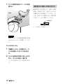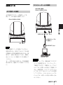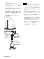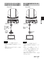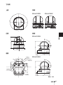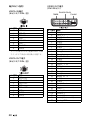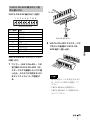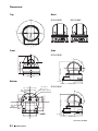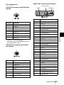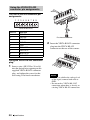
1
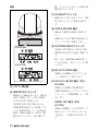
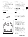
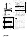
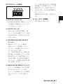
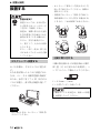
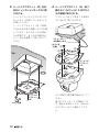
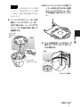
4-299-489-12 (1)
HD Color
Video Camera
取扱説明書 _________________ JP
Operating Instructions _____ GB
お買い上げいただきありがとうございます。
電気製品は安全のための注意事項を守らないと、
火災や人身事故になることがあります。
この取扱説明書には、事故を防ぐための重要な注意事項と製品の取
り扱いかたを示してあります。この取扱説明書をよくお読みのうえ、
製品を安全にお使いください。お読みになったあとは、いつでも見
られるところに必ず保管してください。
EVI-H100S/H100V
Sony Corporation
© 2011 Sony Corporation
安全のために
ソニー製品は正しく使用すれば事故が起きないよう
に、安全には充分配慮して設計されています。
しかし、
電気製品は、
まちがった使いかたをすると、
火災や感
電などにより死亡や大けがなど人身事故につながる
ことがあり、危険です。
事故を防ぐために次のことを必ずお守りください。
安全のための注意事項を守る
4 ∼ 5 ページの注意事項をよくお読みください。
製品全
般および設置の注意事項が記されています。
定期点検を実施する
長期間、安全にお使いいただくために、定期点検をす
ることをおすすめします。
点検の内容や費用について
は、お買い上げ店またはソニーのサービス窓口にご相
警告表示の意味
取扱説明書および製品
で は、
次のような表示
を し て い ま す。
表示の
内容をよく理解してか
ら本文をお読みくださ
い。
この表示の注意事項を
守 ら な い と、火 災 や 感
電などにより死亡や大
けがなど人身事故につ
ながることがありま
す。
談ください。
故障したら使用を中止する
すぐに、お買い上げ店またはソニーのサービス窓口に
ご連絡ください。
万一、異常が起きたら
この表示の注意事項を
守 ら な い と、感 電 や そ
の他の事故によりけが
をしたり周辺の物品に
損害を与えたりするこ
とがあります。
注意を促す記号
・
・
・
・
煙が出たら
異常な音、においがしたら
内部に水、異物が入ったら
製品を落としたりキャビネットを破損したときは
m
行為を禁止する記号
1 電源を切る。
2 電源コードや接続ケーブルを抜く。
3 お買い上げ店またはソニーのサービス窓口に連絡
する。
行為を指示する記号
2
安全のために
目次
はじめに
付録
本機の性能を維持するために ...............6
メッセージ一覧 .............................................23
CMOS 特有の現象 .........................................7
故障かな?と思ったら ............................24
概要
仕様 ....................................................................25
VISCA RS-422 端子のピン配列と
使いかた .............................................29
特長
.......................................................................8
付属品 .....................................................................8
各部の名称と働き ..........................................9
カメラ本体 ..................................................9
保証とアフターサービスに
ついて ..........................................................30
設置と接続
設置する ............................................................14
デスクトップへ設置する ............... 14
三脚に取り付ける ............................... 14
JP
天井に設置する .................................... 15
固定用ネジを使って取り付
ける ....................................................... 18
接続する ............................................................19
AC 電源への接続 ................................ 19
コンピューターとの接続 ............... 19
アナログコンポーネント入力端子
を持つモニターなどとの
接続 ....................................................... 21
DVI 入力端子を持つモニターなど
との接続 ............................................ 21
コンポジットビデオ入力端子を持
つビデオモニターや VTR との
接続 ....................................................... 22
HD-SDI 入力端子を持つ VTR な
どとの接続 ....................................... 22
目次
3
下記の注意を守らないと、火災や感電、落下に
より死亡や大けがにつながることがあります。
電源コードのプラグおよびコネク
ターは突き当たるまで差し込む
まっ直ぐに突き当たるまで差
し込まないと、火災や感電の原
因となります。
水にぬれる場所で使用しない
水ぬれすると、漏電による感
電、
発火の原因となることがあ
ります。
ぬれた手で電源プラグをさわらない
ぬれた手で電源プラグを抜き
差しすると、
感電の原因となる
ことがあります。
分解や改造をしない
分解や改造をすると、火災や感
電、
けがの原因となることがあ
ります。
内部の点検や修理は、お買い上
げ店またはソニーのサービス
窓口にご依頼ください。
設置は専門の工事業者に依頼する
設置については、
必ずお買い上
げ店またはソニーの業務用製
品ご相談窓口にご相談くださ
い。
壁面や天井などへの設置は、
本
機と取り付け金具を含む重量
に充分耐えられる強度がある
ことをお確かめの上、確実に取
り付けてください。
充分な強度
がないと、
落下して大けがの原
因となります。
また、
1年に一度は取り付けが
ゆるんでいないことを点検し
てください。
また、使用状況に
応じて、点検の間隔を短くして
ください。
不安定な場所に設置しない
次のような場所に設置すると
倒れたり落ちたりして、故障や
けがの原因になることがあり
ます。
・ ぐらついた台の上
・ 傾いたところ
・ 振動や衝撃のかかるところ
また、
設置・取り付け場所の強
度を充分にお確かめください。
カメラの取り付けネジは確実に締め
つける
取扱説明書の取り付け方法に
従って確実に組み立てないと、
落下してけがの原因となるこ
とがあります。
4
警告
下記の注意を守らないと、けがをしたり周辺の物品に
損害を与えることがあります。
機器や部品の取り付けは正しく行う
機器や部品の取り付け方や、
本
機の分離・合体の方法を誤る
と、本機や部品が落下して、け
がの原因となることがありま
す。
取扱説明書に記載されている
方法に従って、
確実に行ってく
ださい。
お手入れの際は、電源を切る
電源を接続したままお手入れ
をすると、感電の原因となるこ
とがあります。
注意
5
B はじめに
本機の性能を維持す
るために
使用・保管場所について
・ 化学ぞうきんをご使用の際は、その注
意書に従ってください。
・ 殺虫剤のような揮発性の物をかけた
り、ゴムやビニール製品に長時間接触
させると、変質したり、塗装がはげた
りすることがあります。
次のような場所での使用および保管は
避けてください。故障の原因となりま
定期メンテナンスについて
す。
本機は駆動部を持つ製品であるため、
・ 極端に暑いところや寒いところ(使用
使用条件により、磨耗やグリス切れに
温度は 0 ℃∼ 40 ℃)
・ 直射日光が長時間あたる場所や暖房
器具の近く
よる異音が発生する場合があります。
性能を維持するため、定期メンテナン
スを行うことをおすすめします。異音
・ 強い磁気を発するものの近く
などが発生した場合は、ソニーのサー
・ 強力な電波を発するテレビやラジオ
ビス窓口にご連絡ください。
の送信所の近く
・ 振動や衝撃のあるところ
放熱について
レーザービームについてのご注意
レーザービームは CMOS 撮像素子に
損傷を与えることがあります。レー
動作中は布などで包まないでください。
ザービームを使用した撮影環境では、
内部の温度が上がり、故障や事故の原
撮像素子表面にレーザービームが照射
因となります。
されないように充分注意してくださ
い。
輸送について
輸送するときは、付属のカートンと
クッション、または同等品で梱包し、
強い衝撃を与えないようにしてくださ
い。
本体のお手入れ
・ 汚れがひどいときは、水でうすめた中
性洗剤に柔らかい布をひたし、固くし
ぼってから汚れを拭き取り、乾いた布
で仕上げてください。
・ アルコール、シンナー、ベンジンなど
は使わないでください。変質したり、
塗装がはげたりすることがあります。
6
本機の性能を維持するために
CMOS 特有の現象
撮影画面に出る下記の現象は、CMOS
(Complementary Metal Oxide
はじめに
Semiconductor)特有の現象で、故障で
はありません。
白点
CMOS 撮像素子は非常に精密な技術で
作られていますが、宇宙線などの影響
により、まれに画面上に微小な白点が
発生する場合があります。
これは CMOS 撮像素子の原理に起因す
るもので故障ではありません。
また、下記の場合、白点が見えやすく
なります。
・ 高温の環境で使用するとき
・ GAIN(感度)を上げたとき
本機においては、カメラの電源を切り、
再び電源を入れることで現象が改善す
ることがあります。
折り返しひずみ
細かい模様、線などを撮影すると、ぎ
ざぎざやちらつきが見えることがあり
ます。
CMOS 特有の現象
7
B 概要
特長
付属品
・ 1/2.8 型 Exmor CMOS(有効画素約
梱包をあけたら、以下の付属品が一式
200 万画素)を採用し高感度、高精細
の HD 映像が得られます。
・ 光学倍率 20 倍、F1.6 の高倍率、明る
そろっているか確認してください。
カメラ本体(1)
いズームレンズを搭載しています。
・ ワイドダイナミックレンジ機能の搭
載により、明るい被写体と暗い被写体
を同時に有している画面にて最適映
像が可能となります。
・ 多彩な HD ビデオフォーマット選択と
デジタルとアナログのインター
フェース端子を備えています。
EVI-H100S では長距離伝送に適した
HD-SDI を備えています。EVI-H100V
では DVI-I 端子でデジタル、アナログ
両方の出力に対応しています。
シーリングブラケット (A)(1)
・ レターボックスサイズでの NTSC,
PAL 出力に対応しています。
(EVI-H100S)
・ 外部通信で業界標準である VISCA カ
メラプロトコルの RS-232C インター
フェースを搭載。RS-422 も加えて、長
距離でのコントロールが可能です。
・ 高速、広範囲駆動のパンチルト機能と
Image flip(上下反転)機能により、天
井への設置にも対応が可能となりま
す。
・ カメラの向きや状態を 6 種類まで記憶
できます。
8
特長 / 付属品
シーリングブラケット (B)(1)
ワイヤーロープ (1)
各部の名称と働き
カメラ本体
前面
1
取り付け用ネジ + M3 × 8(8)
概要
VISCA RS-422 コネクタープラグ
(1)
2
取扱説明書(1)
3
4
A レンズ
光学 20 倍ズームレンズです。
B リモコン受光部
C POWER ランプ
電源が入ると点灯します。
このランプが点灯してから、映像が
出力されるまでに約 7 ∼ 16 秒ほど
かかります。
D STANDBY ランプ
スタンバイ状態のとき、点灯しま
す。
各部の名称と働き
9
背面
際、プリセットされていた設定が初
期設定にもどります。
G IR SELECT スイッチ
複数のカメラを 1 台のリモコンで操
作するとき、カメラ番号を決めま
す。
H VISCA RS-422 端子
RS-422 で通信する場合に接続しま
す。
同梱されている VISCA RS-422 コネ
クタープラグをご利用ください。
EVI-H100S
I SYSTEM SELECT スイッチ
VIDEO OUT 端子から出力する映
像信号の出力方式の設定に使用しま
す。
詳しくは、「SYSTEM SELECT ス
イッチの設定」(11 ページ)をご覧
EVI-H100V
ください。
J SD OUT VIDEO 端子
本機からの映像をアナログコンポ
ジット信号として出力します。
E リモコン受光部
F IMAGE FLIP スイッチ
本機からの映像を HD-SDI 信号
(SMPTE292 M シリアルデジタルイ
映像の上下反転を行います。通常は
ンターフェース規格準拠)として出
OFF で使用します。天井に設置す
力します。
るときは ON で使用します。
VIDEO OUT 端子(EVIH100V)
IMAGE FLIP を切り換えるには、
本機の電源が切れている状態(スタ
ンバイ状態も含む)で、その後 DC
電源、VISCA 通信のいずれかで電
源を入れてください。切り換えた
10
K HD OUT HD-SDI 端子(EVIH100S)
各部の名称と働き
本機から映像をデジタル信号として
出力します。アナログコンポーネン
ト信号も、この端子から出力しま
す。
L VISCA IN 端子
O BOTTOM スイッチ
RS-232C で通信する場合に接続しま
RS-232C と RS-422 の切り換え、
す。複数のカメラを接続するとき
ボーレート 9,600bps と 38,400bps の
は、前のカメラの VISCA OUT 端
切り換え、D70 モードへの切り換
子と接続します。
え、IR OUT 出力設定に使用しま
M VISCA OUT 端子
す。詳しくはテクニカルマニュアル
をご覧ください。
複数のカメラを接続するとき、次の
す。
N DC 12 V 端子
ご注意
P 三脚取り付け部
Q 天井設置用ブラケット取り付けネ
ジ穴
重要
この製品には、極性統一形プラグ・
機器の名称と電気定格は、底面に表示さ
JEITA 規格(タイプ 4)をご使用
れています。
ください。
SYSTEM SELECT スイッチの設定
本スイッチを使用して、VIDEO OUT
端子から出力する映像出力方式(ビデ
極性統一形プラグ
底面
オフォーマット)を設定できます。
ご注意
・ スイッチの設定は、本機の電源を入れ
る前に行ってください。スタンバイ状
態での設定も有効となります。スイッ
チの設定後、DC 電源、VISCA 通信の
いずれかで電源を入れてください。
・ スイッチ切り換えの際は、必ずプラスド
ライバーをご使用ください。
指定された工具以外で切り換え操作を行
うと十字溝がつぶれる場合があります。
・ 本機の映像信号出力には、DVI モニ
ターの解像度に合わせて自動的に出力
を選択する機能がありません。必ずモ
ニターの解像度に合わせた設定をして
ください。(EVI-H100V)
・ ハイビジョン映像信号出力は、アスペ
クト比 16:9 のモニターで歪みのない画
像となります。
各部の名称と働き
11
概要
カメラの VISCA IN 端子と接続しま
EVI-H100S/H100V
スイッ 映像出力形式
EVI-H100V EVI-H100S
チ位置 (ビデオ
対応
8
9
A
B
フォーマット)
1080i/
50(25PsF)
1080p/25
720p/50
720p/25
PAL(LB)
C
D
E
F
出力なし
出力なし
出力なし
対応
○
○
○
○
○
○
○
○
○
×
(SD
―
―
―
OUT)
―
―
―
50 Hz
系
―
―
―
○:映像信号が出力される。
希望の映像出力方式に
合わせる。
×:映像信号が出力されない。
LB:Letter Box の略。アスペクト比 4:3
のモニターで歪みのない画像となるよう
に上下に無信号〈黒〉領域を設け、アス
スイッ 映像出力形式
EVI-H100V EVI-H100S
チ位置 (ビデオ
対応
0
1
2
3
フォーマット)
1080i/
59.94(29.97PsF)
1080p/29.97
720p/59.94
720p/29.97
NTSC(LB)
4
5
6
7
12
出力なし
出力なし
VISCA
Control
各部の名称と働き
ペクト比が 16:9 の画像として出力する。
ご注意
対応
・ スイッチ位置が「出力なし」の場合は、
POWER ランプと STANDBY ランプの
○
○
○
○
○
○
○
○
○
×
(SD
―
―
OUT)
―
―
―
―
○
○
―
両方が点灯した状態になります。この
場合は VISCA 通信で制御できません。
59.94 Hz
系
・ VISCA Control では、外部通信でビデ
オフォーマットの設定ができますが、
映像が出力されるまでには他のスイッ
チ位置よりも時間が多くかかります。
詳しくはテクニカルマニュアルを参照
してください。テクニカルマニュアル
については、お買い上げ店にお問い合
わせください。
BOTTOM スイッチの設定
モードを切り換えるには、本機の電
源が切れている状態(スタンバイ状
態を含まない)で BOTTOM スイッ
チを切り換え、その後 DC 電源を入
れてください。
1
2
3
4
5
電源投入後の切り換えには対応しま
EVI-D70/D70P 用の VISCA コマン
E スイッチ 5(未使用)
概要
A D70 モードスイッチ
せん。
常に OFF に設定します。
ドを使用して操作するには、このス
イッチをオンにします。
B IR OUT スイッチ
ON にすると VISCAIN 端子(28
ページ)から赤外線リモコンの受信
信号が出力され、OFF にすると出
力されません。
C RS-232C/RS-422 SELECT
スイッチ
RS-422 インターフェース経由で
VISCA コマンドを使用してカラー
ビデオカメラを操作するにはこのス
イッチを ON にします。
モードを切り換えるには、本機の電
源が切れている状態(スタンバイ状
態を含まない)で BOTTOM スイッ
チを切り換え、その後 DC 電源を入
れてください。電源投入後の切り換
えには対応しません。
D BAUD RATE SELECT スイッチ
ボーレート 38,400bps でカメラを操
作するにはこのスイッチを ON、
ボーレート 9,600bps でカメラを操作
するにはこのスイッチを OFF にし
ます。
各部の名称と働き
13
B 設置と接続
・ カメラヘッド部をパン方向やチルト方
設置する
向へ手で回さないでください。故障の
原因となります。
・ 未接続でカメラヘッド部を手で回すと
設置は確実に
設置については、必ずお買い
本体前面のランプが点灯する場合があ
りますが、これは故障ではありません。
上げ店またはソニーのサービ
ス窓口にご相談ください。
設置は、本機と取り付け金具
を含む重量に充分耐えられる
強度があることをお確かめく
ださい。充分な強度がない
と、落下して、大けがの原因
となります。
また、一年に一度は、取り付
けがゆるんでいないかを点検
してください。
三脚に取り付ける
デスクトップへ設置する
三脚の取付部のネジは取付面から飛び
カメラ本体は、平らなところに置きま
出し量(4)が下記のものを使用し、ハ
す。
ンドドライバーで締めこんでください。
やむを得ず傾いたところに設置すると
きは、パン・チルト動作性能を保証す
るため、水平に対して± 15°以内のと
ころに設置し、落下防止処置を施して
ください。
4 = 4.3 mm ∼ 5 mm
4 = 0.17 インチ∼ 0.20 インチ
三脚用ネジによる固定は、高所への設置
には使用しないでください。
ご注意
・ 持ち運ぶときは、カメラヘッド部を持
たないでください。
14
設置する
天井に設置する
付属のシーリングブラケットとワイ
設置のしかた
1
ヤーロープ、ネジを使って、既存の天
カメラ後面のIMAGE FLIPスイッ
チを ON にする。
井のジャンクションボックスなどにカ
ご注意
メラを取り付けることができます。
設置する際には、水平な天井に設置し
・ BOTTOM スイッチが正しい位置
てください。やむをえず傾きのある天
に設定されているかご確認くださ
井に設置する場合は、傾きが水平面に
い。詳しくは、
「BOTTOM ス
対して± 15° 以内の天井に設置してく
イッチの設定」
(13 ページ)をご
ださい。
覧ください。
・ 電源を入れた後に IMAGE FLIP
警告
スイッチを ON にしても画像は反
転しません。もう一度電源を入れ
門の工事業者に依頼してください。
なおすと反転します。映像が現れ
・ 高所への設置は、設置部および使用す
るまで約 7 ∼ 16 秒ほどかかりま
る取り付け部材(付属品を除く)が、
す。
20kg 以上の重量に充分耐えられる強
・ IMAGE FLIP スイッチの切り換
度があることをお確かめの上、確実に
えをするとプリセットされた設定
取り付けてください。充分な強度がな
はすべて初期設定に戻ります。
いと落下して大けがの原因となりま
す。
・ 落下事故防止のため、付属ワイヤー
2
天井のジャンクションボックスへ
ワイヤーロープを取り付ける
ロープは必ず取り付けてください。
ジャンクションボックスのネジ穴に
・ 高所へ設置した場合は、1 年に一度は
合ったネジ(付属していません)を
取り付けがゆるんでいないことを点
検してください。また、使用状況に応
じて点検の間隔を短くしてください。
お使いください。
天井
設置する前に
カメラの撮影方向を決めてから、天井
にジャンクションボックス、接続ケー
ブル用の各穴を開けておきます。
ご注意
接続ケーブルは、シーリングブラケッ
ト(A)の中を通して配線できません。
接続ケーブル用穴
天井の本体後部の位置に、配線用の穴
が必要です。
設置する
15
設置と接続
・ 天井などの高所に設置する場合は、専
3
シーリングブラケット(B)を天
4
シーリングブラケット(A)を付
井のジャンクションボックスに取
属のネジ(M 3 x 8)3 本でカメ
り付ける。
ラの底面に取り付ける。
ジャンクションボックスのネジ穴に
ブラケットのネジ穴をカメラ本体の
合ったネジ(付属していません)を
穴に合わせて取り付けます。
お使いください。
シーリングブラケット(B)の形状
で丸みがある方の先端にネジ穴が開
いています。あとでカメラの正面に
天井
なる位置です。カメラが正面を向く
よう、向きを調整して取り付けてく
ださい。
ワイヤーロープ
を共締めします
M3x8
(付属) 3
2
1
天井
シーリング
ブラケット
(A)
シーリング
ブラケット
(B)
カメラ正面
ネジは図中の番号順に仮止めしてく
ださい。
3 はワイヤーロープと共締めしま
す。仮止めが終わったら、それぞれ
のネジをしっかりと締めてくださ
い。
16
設置する
5-2 ジャンクションボックス等にワ
ご注意
5
取り付けネジは付属のネジをご使用
イヤーを取り付けられない場合
ください。付属品以外のネジを使用
はシーリングブラケット(B)
した場合、本体内部を破損する恐れ
の下記箇所へ取り付けてくださ
があります。
い。
シーリングブラケット(A)の突
起をシーリングブラケット(B)
の穴に差し込み、シーリングブラ
ケット(A)を後ろ方向へ押して
仮固定する。
天井
6
カメラ前部を押し上げながら、付
属のネジ(M 3 x 8)3 本で 1
から固定する。
天井
シーリング
ブラケット(A)
1
M 3 x 8(付属)
設置する
17
設置と接続
シーリング
ブラケット
(B)
7
カメラ後面の端子にケーブルを接
続する。
固定用ネジを使って取り付ける
底面の取り付け用ネジ穴(M3)3 箇所
を使って固定します。M3 ネジは、次
天井
の規格のものを使用してください。ネ
ジは、金具などの段差のない平面に取
り付け、しっかり締めてください。
M3 ネジ
4 = 3 mm ∼ 5 mm
ご注意
接続したケーブル類は接続部に負荷
がかからないように処理してくださ
い。
カメラの外しかた
1 「設置のしかた」の手順6で、カ
メラを固定したネジ 3 本をはず
す。
2
カメラ全体を天井側へ押し上げな
がら、カメラの前方へ動かす。
フックがはずれ、カメラがはずれま
す。
18
設置する
コンピューターとの接続
接続する
RS-232C 接続
EVI-H100S/H100V
AC 電源への接続
AC 電源アダプターと電源コードを
使って、AC 電源へ接続します。
EVI-H100S/H100V
設置と接続
VISCA IN
DC 12 V
VISCA ケーブル
(別売り)
DC 12 V
RS-232C 入力へ
警告
本機は電源スイッチを備えていません。
設置の際には、容易にアクセスできる固
定配線内に専用遮断装置を設けるか、使
用中に、容易に抜き差しできる、機器に
コンピューター
近いコンセントに電源プラグを接続して
ください。
ご注意
万一、異常が起きた際には、専用遮断装
・ VISCA ケーブル(RS-232C クロスタ
置を切るか、電源プラグを抜いてくださ
イプ)を接続すると、コンピューター
い。
で操作できます。VISCA ケーブルに
ついては、お買い上げ店にご相談くだ
さい。接続方法、コマンドリストにつ
いては、テクニカルマニュアルを参照
してください。テクニカルマニュアル
については、お買い上げ店にお問い合わ
せください。
接続する
19
・ VISCA RS-232C 接続の場合は、カメ
ご注意
ラ底面の BOTTOM スイッチで RS-
・ 付属の VISCA RS-422 コネクタープラ
232C が選択されていることを確認し
グを使って接続ケーブルを製作して
てください(13 ページ)
。
・ VISCA RS-232C 接続時は VISCA RS422 接続を行うことはできません。
ください。ケーブル作成の際は VISCA
RS-422 端子のピン配列(29 ページ)を
参考にして下さい。
・ VISCA RS-232C 接続とVISCA RS-422
・ VISCA RS-422 接続の場合は、カメラ
接続のケーブルを同時に配線しない
底面の BOTTOM スイッチで RS-422
でください。同時に配線すると、カメ
が選択されていることを確認してく
ラが誤動作することがあります。
ださい(13 ページ)。
・ VISCA RS-422 接続時は VISCA RS-
RS-422 接続
EVI-H100S/H100V
232C 接続を行うことはできません。
・ VISCA RS-422 接続とVISCA RS-232C
接続のケーブルを同時に配線しない
でください。同時に配線すると、カメ
ラが誤動作することがあります
VISCA OUT
VISCA RS422 コネク
タープラグ
(付属)
DC 12 V
VISCA RS-422
接続ケーブル
RS-422/
RS-232C 変換コ
ネクタ(別売り)
RS-232C 入力
へ
コンピューター
20
接続する
アナログコンポーネント入力端
子を持つモニターなどとの接続
EVI-H100V
EVI-H100V
DC 12 V
DVI- コンポー
ネント変換
ケーブル(別
売り)
ご注意
・ HD モニターの仕様に合わせて、
DC 12 V
VIDEO OUT
DVI ケーブル
(別売り)
コンポー
ネント入
力端子へ
HD ビデオモニターなど
設置と接続
VIDEO OUT
DVI 入力端子を持つモニターな
どとの接続
DVI 入力
端子へ
HD ビデオモニターなど
ご注意
・ HD モニターの仕様に合わせて、
VIDEO FORMAT の設定をしてくだ
VIDEO FORMAT の設定をしてくだ
さい。
さい。
・ 映像が出力されるまでに約 7 ∼ 16 秒
ほどかかります。
・ DVI ケーブルの性能によっては、ご
くまれに画ノイズが発生することが
あります。動作が保証されている
ケーブルをご使用ください。
・ 映像が出力されるまでに約 7 ∼ 16 秒
ほどかかります。
接続する
21
コンポジットビデオ入力端子を
持つビデオモニターや VTR との
接続
HD-SDI 入力端子を持つ VTR
などとの接続
EVI-H100S
EVI-H100S
SD OUT
VIDEO
DC 12 V
ビデオ接続ケーブル
(別売り)
コンポジットビ
デオ端子へ
HD OUT
HD-SDI
BNC コネ
クター付き
接続ケーブ
ル(別売り)
DC 12 V
HD-SDI 入力
端子へ
HD-SDI 入力端子のある
HDCAM VTR など
ご注意
・ SYSTEM SELECT スイッチを HD が
出力される設定にしてください。詳し
くは、
「SYSTEM SELECT スイッチの
設定」
(11 ページ)をご覧ください。
HD ビデオモニターなど
・ 映像が出力されるまでに約 7 ∼ 16 秒
ほどかかります。
ご注意
・ SYSTEM SELECT スイッチを SD が
出力される設定にしてください。詳し
くは、
「SYSTEM SELECT スイッチの
設定」
(11 ページ)をご覧ください。
・ 映像が出力されるまでに約 7 ∼ 16 秒
ほどかかります。
22
接続する
B 付録
メッセージ一覧
本機に表示されるメッセージは、以下のとおりです。必要に応じて次に示す処置を
行ってください。
ランプ表示
ランプ
意味と対策
STANDBY ランプと
この状態で本機を使用すると故障の原因になります。この場合は、
POWER ランプが交互に
STATUS メニューの PAGE4 に「COOLING FAN:NG」が表示がさ
ゆっくり点滅
れます。本機の電源を切り、お買い上げ店またはソニーのサービス
窓口にご連絡ください。
STANDBY ランプと
SYSTEM SELECT スイッチが「出力なし」に設定されています(11
POWER ランプが点灯
ページ)。
底面の BOTTOM SW5 が ON に設定されています。
画面表示
意味と対策
CAUTION COOLING FAN
この状態で本機を使用すると故障の原因になります。本機の電源を
STOPPED!
切り、お買い上げ店またはソニーのサービス窓口にご連絡ください。
(起動直後に表示)
PRESET n:OK
POSITION 1 ∼ 6 にカメラの状態を記憶させたときに約 3 秒間表示
(n はプリセットのポジショ されます。
ン番号 1 ∼ 6)
RESET n:OK
POSITION 1 ∼ 6 に記憶させた値をリセットしたときに約 3 秒間表
(n はリセットのポジション 示されます。
番号 1 ∼ 6)
ONE PUSH WB:OP
ワンプッシュオートホワイトバランスが実行されているときに点滅
表示されます。
ONE PUSH WB:OK
ワンプッシュオートホワイトバランスが正常に終了したときに点灯
表示されます。
ONE PUSH WB:NG
ワンプッシュオートホワイトバランスが失敗したときに点滅表示さ
れます。
メッセージ一覧
23
付録
メッセージ
故障かな?と思ったら
故障とお考えになる前に下記の項目をもう一度チェックしてみてください。それで
も具合の悪いときは、ソニーのサービス窓口にご相談ください。
症状
原因
接続したビデオモニ
映像接続ケーブルが正しく接続さ 本機とビデオモニターの接続を確認し
処置
ターに画像が出ない。
れていない。
てください。
SYSTEM SELECT スイッチが正
本機の出力ビデオフォーマットとビデ
しく設定されていない。
オモニターの入力ビデオフォーマット
を確認してください。
コンピューターに接続
コンピューターが正しく接続され 本機とコンピューターの接続を確認し
しても VISCA 通信が
ていない。
てください。
できない。
カメラ底面の BOTTOM スイッチ
(13 ページ)で VISCA 通信のボー
レート(9,600 bps または 38,400 bps)
が正しく設定されているか確認してく
ださい。
SYSTEM SELECT スイッチ(11
ページ)が、映像信号が出力される位
置になっているかを確認してくださ
い。
どうしても動作しない。
―
DC 12 V の供給の停止を行い、しば
らくしてからもう一度供給してみてく
ださい。
24
故障かな?と思ったら
水平画角 2.9°(TELE 端)∼
仕様
55.4°(WIDE 端)(1080 ライ
ンモード )
水平画角 2.0°(TELE 端)∼
システム
映像信号
37.6°(WIDE 端)(720 ライ
EVI-H100V:
1920 × 1080p/29.97,
1920 × 1080p/25
ンモード )
最至近撮影距離
10 mm(WIDE 端)∼
1920 × 1080i/
800 mm(TELE 端)
59.94(29.97PsF)
1920 × 1080i/50(25PsF)
1280 × 720p/59.94,
290mm(Default)
最低被写体照度
1.7Lux 以下 (50%, 高感度モー
1280 × 720p/50
ド OFF 時 )
1280 × 720p/29.97
0.5Lux 以下 (50%, 高感度モー
1280 × 720p/25
VISCA CONTROL
(SYSTEM SELECT スイッ
EVI-H100S:
1920 × 1080p/29.97,
シャッタースピード
1 to 1/10000 秒 (22 ステップ )
映像 S/N
パン・チルト機能
水平± 170°
1920 × 1080p/25
最大速度:100°/秒
1920 × 1080i/
垂直+ 90°、− 20°
59.94(29.97PsF)
最大速度:90°/秒
1920 × 1080i/50(25PsF)
1280 × 720p/59.94,
1280 × 720p/50
1280 × 720p/29.97
50 dB
付録
チで切り換え)
ド ON 時 )
入出力端子
映像出力
EVI-H100V:
1280 × 720p/25
COMPONENT(VIDEO
NTSC(Letter Box),
OUT)
:DVI-I 端子
PAL(Letter Box)
Y:1 Vp-p(同期付き、
VISCA CONTROL
75 Ω 終端時)
(SYSTEM SELECT スイッ
チで切り換え)
Pb/Pr:± 350 mVp-p
(75 Ω 終端時)
同期方式
内部同期方式
HD/VD Sync:3.3 Vp-p
映像素子
1/2.8 型 Exmor CMOS
3 値 Sync : ± 300mVp-p
レンズ
光学 20 倍、デジタル 12 倍
(75Ω 終端時)
f = 4.7 mm ∼ 94.0 mm、
DVI Digital(VIDEO
F1.6 ∼ F3.5
OUT)
: DVI-I 端子
EVI-H100S:
COMPOSITE(VBS VIDEO
仕様
25
OUT):1 Vp-p(同期付き、
75 Ω 終端時)
HD-SDI (HD OUT) : BNC 型
800mVp-p、75Ω、
SMPTE292M シリアルイン
ターフェース規格準拠
コントロール入/出力端子
注意
日本国内で使用する電源コードセッ
トは、電気用品安全法で定める基準
を満足した承認品が要求されます。
ソニー推奨の電源コードセットをご
使用ください。
VISCA IN:8 ピンミニ DIN、
RS-232C
VISCA OUT:8 ピンミニ
DIN、RS-232C
本機の仕様および外観は、改良のため
予告なく変更することがありますが、
ご了承ください。
VISCA RS-422:9 ピン
電源端子
JEITA type4(DC 12 V 端子)
この装置は、クラス A 情報技術装置
です。この装置を家庭環境で使用す
その他
ると電波妨害を引き起こすことがあ
入力電圧
DC 12 V(DC 10.8 ∼ 13 V)
ります。この場合には使用者が適切
消費電流
EVI-H100S : 最大 1.0 A
な対策を講ずるよう要求されること
(DC 12 V 入力時)
があります。
VCCI-A
EVI-H100V : 最大 0.92 A
(DC 12 V 入力時)
動作温度
0 ℃∼ 40 ℃
保存温度
− 20 ℃∼+ 60 ℃
外形寸法
本体:145 × 164 × 164 mm
(幅/高さ/奥行き、突起含
まず)
重量
本体:1550g
設置角度
水平に対して± 15°以内
付属品
シーリングブラケット(A)
(1)
シーリングブラケット(B)(1)
ワイヤーロープ(1)
取り付け用ネジ(+ M3 × 8)(8)
VISCA RS-422 コネクタープラグ(1)
取扱説明書(1)
26
仕様
お使いになる前に、必ず動作確認を
行ってください。故障その他に伴う
営業上の機会損失等は保証期間中お
よび保証期間経過後にかかわらず、
補償はいたしかねますのでご了承く
ださい。
寸法図
上面
背面
EVI-H100V
170°
170°
EVI-H100S
正面
側面
付録
EVI-H100S
90
°
164
104
20°
166
Ø145
底面
72
6
Ø5,ᷓߐ5
M3
42
30
164
EVI-H100V
42
1/4-20UNC,ᷓߐ65
ਃ⣉ࡀࠫⓣ
90
°
30
42
14 20
60
20°
53.5
166
31
53.5
77
BOTTOM
ࠬࠗ࠶࠴
M3
M3
51.5
51.5
(Leg)
4-Ø9(A)
72
14
164
単位:mm
仕様
27
端子のピン配列
VIDEO OUT 端子
(DVI 29 ピン)
VISCA IN 端子
(8 ピンミニ DIN、凹)
ピン番号
1
2
3
4
5
6
7
8
* ピン
機能
DTR IN
DSR IN
TXD IN
GND
RXD IN
GND
IR OUT *
未使用
7 の IR OUT は、底面の BOTTOM
スイッチにて出力の切り換え可能です。
VISCA OUT 端子
(8 ピンミニ DIN、凹)
ピン番号
1
2
3
4
5
6
7
8
28
仕様
機能
DTR OUT
DSR OUT
TXD OUT
GND
RXD OUT
GND
未使用
未使用
TMDS
ピン番号
1
2
3
4
5
6
7
8
9
10
11
12
13
14
15
16
17
18
19
20
21
22
23
24
C1
C2
C3
C4
C5
PLUG & PLAY
アナログ
機能
Data_2 −
Data_2 +
Shield(2、4)
未使用
未使用
未使用
未使用
Analog Vertical Sync
Data_1 −
Data_1 +
Shield(1、3)
未使用
未使用
Power_ + 5V
GND
Hot Plug
Data_0 −
Data_0 +
Shield(0、5)
未使用
未使用
Shield Clock
Clock +
Clock −
Analog Pr
Analog Y
Analog Pb
Analog Horizontal Sync
Analog GND
VISCA RS-422 端子のピン配
列と使いかた
ワイヤー
VISCA RS-422 端子のピン配列
1 2 3 4 5 6 7 8 9
VISCA RS-422
機能
TXD IN+
TXD INRXD IN+
RXD INGND
TXD OUT+
TXD OUTRXD OUT+
RXD OUT-
マイナスドライバー
2
VISCA RS-422 コネクタープラ
グをカメラ後面の VISCA RS422 端子へ差し込む。
1 2
3 4
5 6
7 8
9
VISCA RS-422 コネクタープラグ
の使いかた
1
ワイヤー(AW G No.28 ∼ 18)
を付属の VISCA RS-422 コネ
クタープラグの接続したい穴に差
し込み、入れた穴に対応するネジ
をマイナスドライバーで固定す
る。
ご注意
・ 信号の電圧レベルを安定させるた
め、お互いの GND を接続してく
ださい。
・ VISCA RS-422 の接続時は、
VISCA RS-232C との接続は行わ
ないでください。
仕様
29
付録
ピン番号
1
2
3
4
5
6
7
8
9
保証とアフターサー
ビスについて
調子が悪いときはまずチェックを
この取扱説明書をもう一度ご覧になっ
てお調べください。
保証期間と保証条件
本機の保証期間および保証条件は、販
売地域(国内、海外)によって異なる
ことがあります。お手数ですが、お買
い上げ店にお問い合わせ、ご確認いた
だきますようお願い申し上げます。
30
保証とアフターサービスについて
Owner’s Record
The model and serial numbers are located on
the bottom. Record these numbers in the
spaces provided below.
Refer to these numbers whenever you call
upon your Sony dealer regarding this
product.
Model No.
Serial No.
WARNING
To reduce the risk of fire or electric
shock, do not expose this apparatus
to rain or moisture.
To avoid electrical shock, do not
open the cabinet. Refer servicing to
qualified personnel only.
WARNING
This unit has no power switch.
When installing the unit, incorporate a
readily accessible disconnect device in the
fixed wiring, or connect the power plug to an
easily accessible socket-outlet near the unit.
If a fault should occur during operation of
the unit, operate the disconnect device to
switch the power supply off, or disconnect
the power plug.
WARNING
1. Use the approved Power Cord / Appliance
Connector / Plug that conforms to the safety
regulations of each country if applicable.
2. Use the Power Cord / Appliance
Connector / Plug conforming to the proper
ratings (Voltage, Ampere).
in a commercial environment. This
equipment generates, uses, and can radiate
radio frequency energy and, if not installed
and used in accordance with the instruction
manual, may cause harmful interference to
radio communications. Operation of this
equipment in a residential area is likely to
cause harmful interference in which case the
user will be required to correct the
interference at his own expense.
You are cautioned that any changes or
modifications not expressly approved in this
manual could void your authority to operate
this equipment.
All interface cables used to connect
peripherals must be shielded in order to
comply with the limits for a digital device
pursuant to Subpart B of Part 15 of FCC
Rules.
This device complies with Part 15 of the
FCC Rules. Operation is subject to the
following two conditions: (1) this device
may not cause harmful interference, and (2)
this device must accept any interference
received, including interference that may
cause undesired operation.
For the customers in Canada
This Class A digital apparatus complies with
Canadian ICES-003.
For the customers in Europe,
Australia and New Zealand
IMPORTANT
The nameplate is located on the bottom.
WARNING
This is a Class A product. In a domestic
environment, this product may cause radio
interference in which case the user may be
required to take adequate measures.
In the case that interference should occur,
consult your nearest authorized Sony service
facility.
For the customers in the U.S.A.
This equipment has been tested and found to
comply with the limits for a Class A digital
device, pursuant to Part 15 of the FCC
Rules. These limits are designed to provide
reasonable protection against harmful
interference when the equipment is operated
For the customers in Europe
The manufacturer of this product is Sony
Corporation, 1-7-1 Konan, Minato-ku,
Tokyo, Japan.
The Authorized Representative for EMC
and product safety is Sony Deutschland
GmbH, Hedelfinger Strasse 61, 70327
If you have questions on the use of the above
Power Cord / Appliance Connector / Plug,
please consult a qualified service personnel.
31
GB
Stuttgart, Germany. For any service or
guarantee matters please refer to the
addresses given in separate service or
guarantee documents.
This apparatus shall not be used in the
residential area.
Caution for U.S.A. and CANADA
The unit must always be operated with a
rated 12 V dc, 1.0 A max. (for EVI-H100S)/
0.92 A max. (for EVI-H100V) power supply
marked “Class 2” or “LPS.”
In the USA, use an UL Listed power supply.
In Canada, use a CSA-certified power
supply.
Caution for other countries
This product is intended to be supplied by an
EN60950-1 and/or IEC60950-1 applied
power supply, rated 12 V dc, 1.0 A max. (for
EVI-H100S)/0.92 A max. (for EVI-H100V)
and limited power sources.
AVERTISSEMENT
Afin de réduire les risques d’incendie
ou d’électrocution, ne pas exposer
cet appareil à la pluie ou à l’humidité.
Afin d’écarter tout risque
d’électrocution, garder le coffret
fermé. Ne confier l’entretien de
l’appareil qu’à un personnel qualifié.
AVERTISSEMENT
Cet appareil ne possède pas d’interrupteur
d’alimentation.
Lors de l’installation de l’appareil,
incorporer un dispositif de coupure dans le
câblage fixe ou brancher la fiche
d’alimentation dans une prise murale
facilement accessible proche de l’appareil.
En cas de problème lors du fonctionnement
de l’appareil, enclencher le dispositif de
coupure d’alimentation ou débrancher la
fiche d’alimentation.
AVERTISSEMENT
1. Utilisez un cordon d’alimentation /fiche
femelle / fiche mâle conformes à la
réglementation de sécurité locale applicable.
2. Utilisez un cordon d’alimentation /fiche
femelle / fiche mâle avec des
32
caractéristiques nominales (tension,
ampérage) appropriées.
Pour toute question sur l’utilisation du
cordon d’alimentation/fiche femelle/fiche
mâle ci-dessus, consultez un technicien du
service après-vente qualifié.
IMPORTANT
La plaque signalétique se situe sous
l’appareil.
Pour les clients au Canada
Cet appareil numérique de la classe A est
conforme à la norme NMB-003 du Canada.
Pour les clients en Europe, Australie
et Nouvelle-Zélande
AVERTISSEMENT
Il s’agit d’un produit de Classe A. Dans un
environnement domestique, cet appareil
peut provoquer des interférences radio, dans
ce cas l’utilisateur peut être amené à prendre
des mesures appropriées.
Si des interférences se produisent, contactez
votre service après-vente agréé Sony.
Pour les clients en Europe
Le fabricant de ce produit est Sony
Corporation, 1-7-1 Konan, Minato-ku,
Tokyo, Japon.
Le représentant autorisé pour EMC et la
sécurité des produits est Sony Deutschland
GmbH, Hedelfinger Strasse 61, 70327
Stuttgart, Allemagne. Pour toute question
concernant le service ou la garantie, veuillez
consulter les adresses indiquées dans les
documents de service ou de garantie séparés.
Ne pas utiliser cet appareil dans une zone
résidentielle.
WARNUNG
Um die Gefahr von Bränden oder
elektrischen Schlägen zu verringern,
darf dieses Gerät nicht Regen oder
Feuchtigkeit ausgesetzt werden.
Um einen elektrischen Schlag zu
vermeiden, darf das Gehäuse nicht
geöffnet werden. Überlassen Sie
Wartungsarbeiten stets nur
qualifiziertem Fachpersonal.
WARNUNG
Dieses Gerät hat keinen Netzschalter.
Beim Einbau des Geräts ist daher im
Festkabel ein leicht zugänglicher
Unterbrecher einzufügen, oder der
Netzstecker muss mit einer in der Nähe des
Geräts befindlichen, leicht zugänglichen
Wandsteckdose verbunden werden. Wenn
während des Betriebs eine Funktionsstörung
auftritt, ist der Unterbrecher zu betätigen
bzw. der Netzstecker abzuziehen, damit die
Stromversorgung zum Gerät unterbrochen
wird.
Für Kunden in Europa
Der Hersteller dieses Produkts ist Sony
Corporation, 1-7-1 Konan, Minato-ku,
Tokyo, Japan.
Der autorisierte Repräsentant für EMV und
Produktsicherheit ist Sony Deutschland
GmbH, Hedelfinger Strasse 61, 70327
Stuttgart, Deutschland. Bei jeglichen
Angelegenheiten in Bezug auf
Kundendienst oder Garantie wenden Sie
sich bitte an die in den separaten
Kundendienst- oder Garantiedokumenten
aufgeführten Anschriften.
Dieser Apparat darf nicht im Wohnbereich
verwendet werden.
WARNUNG
1. Verwenden Sie ein geprüftes Netzkabel/
einen geprüften Geräteanschluss/einen
geprüften Stecker entsprechend den
Sicherheitsvorschriften, die im betreffenden
Land gelten.
2. Verwenden Sie ein Netzkabel/einen
Geräteanschluss/einen Stecker mit den
geeigneten Anschlusswerten (Volt,
Ampere).
Wenn Sie Fragen zur Verwendung von
Netzkabel/Geräteanschluss/Stecker haben,
wenden Sie sich bitte an qualifiziertes
Kundendienstpersonal.
WICHTIG
Das Namensschild befindet sich auf der
Unterseite des Gerätes.
Für Kunden in Europa, Australien
und Neuseeland
WARNUNG
Dies ist eine Einrichtung, welche die FunkEntstörung nach Klasse A besitzt. Diese
Einrichtung kann im Wohnbereich
Funkstörungen verursachen; in diesem Fall
kann vom Betreiber verlangt werden,
angemessene Maßnahmen durchzuführen
und dafür aufzukommen.
Sollten Funkstörungen auftreten, wenden
Sie sich bitte an den nächsten autorisierten
Sony-Kundendienst.
33
Table of Contents
Getting Started
Appendix
Precautions ....................................... 35
Phenomena Specific to CMOS Image
Sensors .............................................36
Message List .................................... 50
Troubleshooting............................... 51
Specifications .................................. 52
Using the VISCA RS-422 connector
pin assignments .............. 56
Overview
Features ............................................ 37
Supplied Accessories .......................37
Location and Functions of Parts and
Controls ............................................38
Camera ........................................38
Installation and Connection
Installing the Camera ....................... 42
Installing the Camera on a
Desk ................................42
Attaching the Camera to a
Tripod ..............................42
Installing the unit on the
ceiling ..............................42
Installing the Camera Using the M3
Fixing Screw Holes .........46
Connections ......................................46
Connecting to an AC Outlet .......46
Connecting a Computer ..............47
Connecting a Video Monitor, etc.,
Equipped with an Analog
Component Input
Connector ........................48
Connecting a Video Monitor, etc.,
Equipped with DVI Input
Connector ........................48
Connecting a Video Monitor, etc.,
Equipped with a Composite
video Input Connector .....49
Connecting a VTR, etc., Equipped
with HD-SDI Input
Connector ........................49
34
Table of Contents
B Getting Started
Precautions
Operating or storage location
Note on laser beams
Laser beams may damage the CMOS
image sensors. If you shoot a scene that
includes a laser beam, be careful not to let
a laser beam become directed into the
image sensors of the camera.
Ventilation
To prevent heat buildup, do not block air
circulation around the camera.
Transportation
When transporting the camera, repack it as
originally packed at the factory or in
materials equal in quality.
Cleaning the main unit
• When the body of the camera is dirty,
clean it with a soft cloth that is soaked with
a diluted neutral detergent and tightly
wrung. Then finish with a dry cloth.
• Do not use any type of solvents, which
may damage the finish.
• When you use a chemical cloth, follow its
instructions.
• Do not sprinkle volatile matter such as
pesticide over your camera nor allow
rubber or vinyl to come in contact with the
camera for a long period of time. Doing so
may damage the finish.
Maintenance
The camera mechanism may cause abnormal
noise due to wear and lubrication loss after a
long period of use. To maintain optimum
performance, we recommend periodical
Precautions
35
Getting Started
Operating or storing the camera in the
following locations may cause damage to
the camera:
• Extremely hot or cold places (Operating
temperature: 0 °C to 40 °C
[32 °F to 104 °F])
• Exposed in direct sunlight for a long time,
or close to heating equipment (e.g., near
heaters)
• Close to sources of strong magnetism
• Close to sources of powerful
electromagnetic radiation, such as radios
or TV transmitters
• Locations subject to vibration or shock
maintenance. If abnormal noise occurs,
consult your Sony dealer.
Phenomena Specific
to CMOS Image
Sensors
The following phenomena that may appear
in images are specific to CMOS
(Complementary Metal Oxide
Semiconductor) image sensors. They do not
indicate malfunctions.
White flecks
Although the CMOS image sensors are
produced with high-precision technologies,
fine white flecks may be generated on the
screen in rare cases, caused by cosmic rays,
etc. This is related to the principle of CMOS
image sensors and is not a malfunction.
White flecks tend to be seen particularly in
the following cases:
• during operation at a high environmental
temperature
• when you have raised the gain (sensitivity)
This phenomena may be improved by
turning the camera off and then on again.
Aliasing
When fine patterns, stripes, or lines are shot,
they may appear jagged or flicker.
36
Phenomena Specific to CMOS Image Sensors
B Overview
Features
When you unpack, check that all the
supplied accessories are included.
Camera (1)
Overview
• The 1/2.8 type Exmor CMOS camera
(utilising approximately 2 million valid
pixels) allows for high-definition shooting
with superior picture quality.
• Adopts 20 times optical magnification,
F1.6 high power and luminous zoom lens.
• By adopting its wide and dynamic range
functions, you can see the optimised
shooting image which incorporates bright
and dark subjects at the same time.
• The camera has a variety of HD video
format choices and digital and analogue
interface connectors. The EVI-H100S
camera has HD-SDI (High DefinitionSerial Digital Interface) output, suitable
for long-distance transmission. The EVIH100V camera has a DVI-I (VIDEO
OUT) connector supporting both digital
and analogue output.
• The camera can be used for NTSC and
PAL output in letter box size
(EVI-H100S).
• Adopts the industry standard RS-232C
interface of VISCA camera protocol in
external communication. It is possible to
operate from long distances by using both
RS-232C and RS-422.
• You can install the camera on ceilings due
to the functions of high-speed and wide
range pan/tilt action and vertical image
flip.
• You can store up to 6 kinds of camera
direction and camera status into the
camera.
Supplied
Accessories
Ceiling bracket (A) (1)
Ceiling bracket (B) (1)
Features / Supplied Accessories
37
Wire rope (1)
Location and
Functions of Parts
and Controls
Camera
Screw +M 3×8 (8)
Front
1
VISCA RS-422 connector plug (1)
Operating Instructions (1)
2
3
4
A Lens
This is a 20-magnification optical zoom
lens.
B Remote sensors
C POWER lamp
Lights when the camera is turned on.
It takes about 7 to 16 seconds to display
the image after the lamp lights.
D STANDBY lamp
Lights when the camera is set to standby
mode.
38
Location and Functions of Parts and Controls
G IR SELECT switch
Rear
Select the camera number when you
operate multiple cameras with the same
remote commander.
H VISCA RS-422 connector
To communicate via RS-422, use this
connector.
Use the supplied VISCA RS-422
connector plug.
Used for selecting the video format of
the signal to be output from the VIDEO
OUT connectors.
For details, see “Setting of the SYSTEM
SELECT switch” (page 40).
J SD OUT VIDEO connector
EVI-H100S
Supplies the images as an analog
component signal.
K HD OUT HD-SDI connector (EVIH100S)
Supplies the images as HD-SDI signal
(compliant with SMPTE 292M).
EVI-H100V
VIDEO OUT connector (EVIH100V)
Supplies the image as digital signals. An
analog component signal is also output
from this connector.
L VISCA IN connector
E Remote sensors
F IMAGE FLIP switch
Flips the image upside down. Normally
set this to OFF when you use the camera.
When the camera is attached to the
ceiling, set this to ON. Before you set the
IMAGE FLIP switch, turn off the unit
(or set to standby mode) and then, turn
the power on by connecting the power
adaptor or by VISCA control. When you
switch this, the preset setting is returned
to the initial setting.
Connect to a computer via an RS-232C
interface. When you connect multiple
cameras, connect it to the VISCA OUT
connector of the previous camera in the
daisy chain connection.
M VISCA OUT connector
When you connect multiple cameras,
connect it to the VISCA IN connector of
the next camera in the daisy chain
connection.
N DC 12 V connector
Note
Use only the polarity plug (standard
JEITA/type 4).
Location and Functions of Parts and Controls
39
Overview
I SYSTEM SELECT switch
Notes
Polarity of the plug
Bottom
• Be sure to set this switch before you turn
on the power of the camera. You can also
set this switch in the standby mode of the
camera. After completing the setting, turn
on the power of the camera by connecting
it to an AC outlet using the AC power
adaptor and AC power cord or by using the
VISCA command.
• Be sure to use a Phillips-head screwdriver
when changing the switch position. If you
use a tool other than the designated
screwdriver, the crossed groove may be
damaged.
• This camera does not include a function
that automatically selects video output
signals based on the DVI monitor’s
resolution. Be sure to configure settings
based on the monitor manually. (EVIH100V)
• HDTV video signal outputs display
without distortion on monitors with 16:9
aspect ratios.
EVI-H100S/H100V
O BOTTOM switches
Used for RS-232C and RS-422
switching, 9,600bps and 38,400bps baud
rate selection, D70 mode switching and
IR signal output setting. For detailed
information, refer to the Technical
Manual of the camera.
P Tripod screw hole
Q Ceiling bracket mounting screw
holes
Important
The nameplate is located on the bottom.
Setting of the SYSTEM SELECT
switch
This switch allows you to select the video
format of the signal to be output from the
VIDEO OUT connectors.
40
Location and Functions of Parts and Controls
Set this arrow to
the desired video
format.
Switch Video
position format
For detailed information, refer to the
Technical Manual of the camera. For details
on obtaining a Technical Manual, consult
your Sony dealer.
EVI-H100V EVI-H100S
support
support
0
1080i/
59.94(29.97
PsF)
Yes
Yes
1
1080p/29.97
Yes
Yes
2
720p/59.94
3
720p/29.97
Yes
Yes
Yes
Yes
Setting of the BOTTOM switches
59.94 Hz
system
–
No output
–
–
–
7
VISCA
Control
Yes
Yes
–
8
1080i/
50(25PsF)
Yes
Yes
9
1080p/25
Yes
Yes
A
720p/50
B
720p/25
Yes
Yes
Yes
Yes
50 Hz
system
–
–
–
D
No output
–
Yes
(SD
OUT)
–
E
No output
F
No output
–
–
–
–
PAL(LB)
No
C
1
2
3
4
5
No output
6
No
Overview
5
Yes
(SD
OUT)
–
NTSC(LB)
4
–
A D70 mode switch
Set to ON to use the VISCA command
for EVI-D70/D70P.
B IR OUT switch
Set to ON to enable output of the
receiver signals, which are transmitted
from the infrared remote commander via
the VISCA IN connector (page 55), or
set it to OFF to disable the output.
C RS-232C/RS-422 select switch
Yes: Outputs the image signal.
No: Does not output the image signal.
LB: Abbreviation of LETTER BOX. A
video signal with the 16:9 aspect ratio
is output by adding a blank area (no
signal, black) top and bottom to
display the image without distortion on
a monitor that uses the 4:3 aspect ratio.
Notes
• If the switch position is set to “no output,”
the POWER lamp and STANDBY lamp
will both remain lit. In such cases, control
via VISCA commands is disabled.
• The VISCA Control switch position
allows you to configure the video format
via external communication. However,
video output will take longer compared to
other switch positions.
Set to ON to operate colour video
camera using the VISCA command via
the RS-422 interface. To change the
mode, turn off the camera (not including
standby mode) first, set the switch and
then turn on the camera again. The mode
cannot be switched while the camera is
turned on.
D Baud rate select switch
Set to ON for 38,400 bps or OFF for
9,600 bps. To change the mode, turn off
the camera (not including standby
mode) first, set the switch and then turn
on the camera again. Mode switching is
not possible while the camera is turned
on.
E Switch 5 (Not used)
Be sure to set this switch to OFF.
Location and Functions of Parts and Controls
41
B Installation and Connection
Installing the
Camera
Installing the Camera on a
Desk
Place the camera on a flat surface.
If you have to place the camera on an
inclined surface, make sure that the
inclination is less than ±15 degrees to
guarantee pan/tilt performance, and take
measures to prevent it from falling.
Attaching the Camera to a
Tripod
Attach a tripod to the screw hole used for
attaching a tripod on the bottom of the
camera.
The tripod must be set up on a flat surface
and its screws tightened firmly by hand.
Use a tripod with screws of the following
specifications.
4 = 4.3 - 5 mm
4 = 0.17 - 0.20 inches
Caution
Installation of the camera using the
tripod screws and screw holes should not
be done for installation on a ceiling or a
shelf, etc., in a high position.
Notes
• Do not grasp the camera head when
carrying the camera.
• Do not turn the camera head by hand.
Doing so may result in a camera
malfunction.
• If you turn the camera head by hand
without DC 12 V connection, the lamps on
the front may light. This is not a
malfunction.
Installing the unit on the
ceiling
Using the ceiling bracket, wire rope, and
retaining screws supplied, you can utilize
existing junction boxes, etc., to attach the
camera to the ceiling.
When you install the unit, always install it on
a level ceiling. If you have to install it on a
sloping or uneven ceiling, make sure that the
place where you install it is within ±15
degrees of the horizontal.
CAUTION
• Entrust installation to an experienced
contractor or installer when installing the
unit on ceilings or other high locations.
• When installing the unit in a high location,
be sure that the location and installation
components (excluding the supplied
accessories) are strong enough to
withstand at least 20 kg of weight, and
install the unit securely. If the components
are not strong enough, the unit may fall
and cause serious injury.
42
Installing the Camera
• Always install the supplied wire rope to
prevent the unit from falling.
• If you install the unit in a high location,
check periodically, at least once a year, to
ensure that the connection has not
loosened. If conditions warrant, make this
periodic check more frequently.
2
Attach the wire rope to the junction
box in the ceiling.
Use a screw hole and a screw (not
supplied) in the junction box to attach
the wire rope.
Ceiling
Before installation
After deciding the direction in which the
camera will shoot, make the required holes
for the junction box, and connecting cables.
Note
Installation
1
Installation and Connection
The connecting cables cannot be passed
through ceiling bracket (A). A hole for the
wiring is required in the ceiling at the back
of the unit where it is attached to the ceiling.
Hole for connecting cable
Set the IMAGE FLIP switch on the
rear panel to ON.
Notes
• Make sure that the BOTTOM switch is
set to the correct position. See “Setting
of the BOTTOM switches” (page 41).
• If you set the IMAGE FLIP switch to
ON after turning on the power, the
image will not be flipped. Turn the
power off once, then on again, and the
image will be flipped. It takes about 7
to 16 seconds to display the image.
• When you toggle the IMAGE FLIP
switch, the pre-set settings will all be
returned to the initial settings.
Installing the Camera
43
3
Attach the ceiling bracket (B) to the
junction box on the ceiling.
Align the holes in the bracket with those
in the junction box, and use appropriate
screws (not supplied).
There are elongated holes for the screws
along the rounded edges of the ceiling
bracket (B). Later, the front of the
camera will be positioned along this
edge. Face the camera to the front, adjust
the aim, and attach it securely.
4
Attach the ceiling bracket (A) to the
bottom of the camera using the 3
screws (M 3 × 8) supplied.
Align the screw holes on the bottom of
the camera with those in the ceiling
bracket, and attach the bracket to the
camera.
Ceiling
Attach the wire rope at
the same time.
M3×8
(supplied)
Ceiling
3
2
1
Ceiling
bracket (A)
Ceiling
bracket (B)
Front of the camera
Tighten the screws a bit at a time in the
numbered order shown in the illustration.
Attach the wire rope using the screw
designated as number 3 above. After all of
the screws are inserted and temporarily
tightened properly, securely tighten each
one in turn.
Note
For assembly, use only the screws supplied
with the unit. Using other screws may
damage the unit.
44
Installing the Camera
5
Insert the protrusions raised on the
ceiling bracket (A) into the spaces
prepared in the ceiling bracket (B),
and temporarily attach them by
pushing the ceiling bracket (A) to the
rear.
Ceiling
bracket
(B)
6
While pushing up on the front part of
the camera, attach it using the three
screws provided (M 3 × 8), starting
with the screw at position 1.
Ceiling
Ceiling
1
Ceiling
bracket (A)
5-2 If the wire cannot be attached to the
7
Connect the cables to the connectors
on the rear of the camera.
Ceiling
junction box, attach to the position
on the ceiling bracket (B) in the
illustration.
Note
Take the proper steps to ensure that the
load of the cables connected does not
cause problems.
Installing the Camera
45
Installation and Connection
M 3 × 8 (supplied)
Removing the camera
Connections
1
Remove the 3 screws used to attach
the camera in step 6 of “Installation.”
2
While pushing the entire camera up
towards the ceiling, move the camera
to the front.
The hooks will disengage, and you can
remove the camera.
Connecting to an AC Outlet
Use the AC power adaptor and AC power
cord to connect the camera to an AC outlet.
EVI-H100S/H100V
Installing the Camera Using
the M3 Fixing Screw Holes
Attach the camera using 3 M3 fixing screw
holes located on the bottom of the camera.
Attach the camera to a fitting with a flat
surface using M3 screws with the following
specifications.
M3 screw
4 = 3 – 5 mm
4 = 1/8 – 7/32 inches
46
Connections
DC 12 V
Connecting a Computer
RS-232C Connections
EVI-H100S/H100V
• Do not mix VISCA RS-232C (cross) and
VISCA RS-422 cables. Using these cables
at the same time may result in
malfunction.
To obtain a cable, consult your Sony dealer.
For detailed information on how to connect
the camera and the VISCA command list,
refer to the Technical Manual of the camera.
For details on obtaining a Technical
Manual, consult your Sony dealer.
RS-422 Connections
EVI-H100S/H100V
Installation and Connection
VISCA IN
DC 12 V
VISCA cable
(not supplied)
to RS-232C input
VISCA OUT
VISCA RS-422
connector plug
(supplied)
DC 12 V
VISCA RS-422
cable
RS-422 to RS-232C
converter (not
supplied)
Computer
to RS-232C input
Notes
• When you connect a computer to the
camera using the VISCA cable (RS-232C
cross cable), you can control the camera
from a computer.
• In the case of VISCA RS-232C
connection, make sure that the BOTTOM
switch is set to RS-232C (page 41).
• It is not possible to connect both VISCA
RS-232C and VISCA RS-422
simultaneously.
Computer
Notes
• Make up the cable using the supplied
VISCA RS-422 connector plug. See
“Using the VISCA RS-422 connector pin
assignments” (page 56).
Connections
47
• In the case of VISCA RS-232C
connection, make sure that the BOTTOM
switch is set to RS-232C (page 41).
• It is not possible to connect both VISCA
RS-232C and VISCA RS-422
simultaneously.
• Do not mix VISCA RS-232C (cross) and
VISCA RS-422 cables. Using these cables
at the same time may result in
malfunction.
Notes
• Configure the, VIDEO FORMAT, based
on the specifications of the HD monitor.
• It takes about 7 to 16 seconds to display
the image.
Connecting a Video Monitor,
etc., Equipped with DVI Input
Connector
EVI-H100V
Connecting a Video Monitor,
etc., Equipped with an Analog
Component Input Connector
EVI-H100V
VIDEO OUT
VIDEO OUT
DC 12 V
DC 12 V
DVI cable (not
supplied)
DVI to component
adapter cable
(not supplied)
to DVI
input connector
to component
input
connector
HD video monitor, etc.
Notes
HD video monitor, etc.
48
Connections
• Configure the, VIDEO FORMAT, based
on the specifications of the HD monitor.
• Depending on the performance
capabilities of the DVI cable, some picture
noise may occur. In particular, be sure to
use a cable for which performance is
guaranteed.
• It takes about 7 to 16 seconds to display
the image.
Connecting a Video Monitor,
etc., Equipped with a
Composite video Input
Connector
Connecting a VTR, etc.,
Equipped with HD-SDI Input
Connector
EVI-H100S
EVI-H100S
Cable with
BNC connector
(not supplied)
SD OUT
VIDEO
Installation and Connection
HD OUT
HD-SDI
DC 12 V
to HD-SDI input
connector
DC 12 V
Video cable
(not supplied)
HDCAM VTR with HD-SDI
input connector, etc.
Notes
to composite video
connector
• Set the SYSTEM SELECT switch to
output the SD video format.
For details, see “Setting of the SYSTEM
SELECT switch” (page 40).
• It takes about 7 to 16 seconds to display
the image.
HD video monitor, etc.
Notes
• Set the SYSTEM SELECT switch to
output the SD video format.
• It takes about 7 to 16 seconds to display
the image.
Connections
49
B Appendix
Message List
The following messages and indications may appear for this camera. Perform the following as
necessary.
Lamp display
Lamp
Meaning and solution
The STANDBY lamp and Operating the camera in this state may result in malfunction. In this
POWER lamp flash slowly case, “COOLING FAN:NG” appears on PAGE4 of the STATUS
in alternation.
menu. Turn off the camera, and consult your Sony dealer.
The STANDBY lamp and
POWER lamp are lit.
The SYSTEM SELECT switch is set to “no output” (page 40).
Set BOTTOM switch (5) to ON.
Screen display
Message
Meaning and solution
CAUTION COOLING
Operating the camera in this state may result in malfunction. Turn
FAN STOPPED!
off the camera, and consult your Sony dealer.
(appears immediately after
startup)
PRESET n:OK
(“n” is a preset position
number between 1 and 6)
This message appears for about 3 seconds when you store camera
settings to POSITION 1 to 6.
RESET n:OK
(“n” is a reset position
number between 1 and 6)
This message appears for about 3 seconds when you reset camera
settings stored in POSITION 1 to 6.
ONE PUSH WB:OP
During the white balance adjustment in the ONE PUSH white
balance mode, this message blinks on the screen.
ONE PUSH WB:OK
When the white balance adjustment has been done correctly in the
ONE PUSH white balance mode, this message is lit on the screen.
ONE PUSH WB:NG
When the white balance adjustment has failed in the ONE PUSH
white balance mode, this message blinks on the screen.
50
Message List
Troubleshooting
Before bringing in your camera for service, check the following as a guide to troubleshooting
the problem. If the problem cannot be corrected, consult your Sony dealer.
Symptom
Cause
The picture is not
displayed on the video
monitor connected to the
camera.
The video cable is not connected Check the connection between
properly.
the camera and video monitor.
Remedy
The SYSTEM SELECT switch
on the rear of the camera is not
set correctly.
Check the selected output signal
format of the camera and the
input signal format of the
connected monitor.
The VISCA control is not
available with a computer
connected to the camera.
The computer is not correctly
connected to the camera.
Make sure the connection
between the computer and
camera is made correctly.
Check that the baud rate setting
(9,600 bps or 38,400 bps) is
properly made with the
BOTTOM switch on the bottom
of the camera (page 41).
The camera cannot be
operated at all.
-
Stop power to the DC 12 V
connector. After a few moments,
apply power again.
Troubleshooting
51
Appendix
Check that the SYSTEM
SELECT switch (page 40) is set
to a position in which video
signals are output.
Maximum tilting speed:
90 degrees/sec.
Specifications
System
Video signal EVI-H100V:
1920 × 1080p/29.97,
1920 × 1080p/25,
1920 ×1080i/59.94 (29.97PsF),
1920 ×1080i/50 (25PsF),
1280 × 720p/59.94,
1280 × 720p/50,
1280 × 720p/29.97,
1280 × 720p/25,
VISCA CONTROL (switched
with the SYSTEM SELECT
switch)
EVI-H100S:
1920 × 1080p/29.97,
1920 × 1080p/25,
1920 × 1080i/59.94 (29.97PsF),
1920 × 1080i/50 (25PsF),
1280 × 720p/59.94,
1280 × 720p/50,
1280 × 720p/29.97,
1280 × 720p/25,
NTSC(Letter Box),
PAL(Letter Box),
VISCA CONTROL (switched
with the SYSTEM SELECT
switch)
Synchronization
Internal synchronization
Image device 1/2.8 type Exmor CMOS
Lens
20× (optical), 12× (digital)
f = 4.7 – 94.0 mm, F1.6 – F3.5
Horizontal angle:
2.9 (TELE end) to 55.4 degrees
(WIDE end) (1080 line mode)
2.0 (TELE end) to 37.6 degrees
(WIDE end) (720 line mode)
Minimum object distance
10 mm (0.4 inches) (WIDE end) to
800 mm (31.5 inches) (TELE
end) 290 mm (11 27/64 inches)
(Default)
Minimum illumination
Less or equal to1.7 lux (50%, highsensitivity mode off)
Less or equal to 0.5 lux (50%,
high-sensitivity mode on)
Shutter speed 1 to 1/10,000 sec. (22 steps)
Video S/N
50 dB
Pan/tilt action Horizontal: ±170 degrees
Maximum panning speed:
100 degrees/sec.
Vertical: +90, –20 degrees
52
Specifications
Input/output connectors
Video output EVI-H100V:
COMPONENT (VIDEO OUT):
DVI-I connector
Y: 1 Vp-p (sync, at 75-ohm
termination)
Pb/Pr: ±350 mVp-p
(75-ohm termination)
3 values Sync : ±300mV p-p
(75-ohm termination)
HD/VD Sync: 3.3 Vp-p
DVI Digital VIDEO (VIDEO
OUT): DVI-I connector
EVI-H100S:
COMPOSITE (VBS VIDEO
OUT):
1 Vp-p (sync, at 75-ohm
termination)
HD-SDI (HD OUT) : BNC type
800mVp-p, 75-ohm
SMPTE292M compliant with
serial interface
Control input/output
VISCA IN: Mini DIN 8-pin type,
RS-232C
VISCA OUT: Mini DIN 8-pin
type, RS-232C
VISCA RS-422: 9-pin
Power connector
JEITA type4 (DC 12 V)
General
Input voltage 12 V DC (10.8 to 13.0 V DC)
Current consumption
EVI-H100S : 1.0 A max. (at 12 V
DC)
EVI-H100V : 0.92 A max. (at 12 V
DC)
Operating temperature
0 ºC to 40 ºC (32 ºF to 104 ºF)
Storage temperature
–20 ºC to +60 ºC (–4 ºF to 140 ºF)
Dimensions Video camera:
145 × 164 × 164 mm
(5 1/32 × 6 15/32 ×
6 15/32 inches, excluding
protruding parts)
(w/h/d)
Mass
Video camera: Approx. 1550g
(3 lb 6 5/8 oz)
Installation angle
Less than ±15 degrees to the
horizontal surface
Supplied accessories
Ceiling bracket (A) (1)
Ceiling bracket (B) (1)
Wire rope (1)
Screw M3×8 (8)
VISCA RS-422 connector plug (1)
Operating Instructions (1)
Design and specifications are subject to
change without notice.
Appendix
Note
Always verify that the unit is operating
properly before use. SONY WILL NOT
BE LIABLE FOR DAMAGES OF ANY
KIND INCLUDING, BUT NOT
LIMITED TO, COMPENSATION OR
REIMBURSEMENT ON ACCOUNT
OF THE LOSS OF PRESENT OR
PROSPECTIVE PROFITS DUE TO
FAILURE OF THIS UNIT, EITHER
DURING THE WARRANTY PERIOD
OR AFTER EXPIRATION OF THE
WARRANTY, OR FOR ANY OTHER
REASON WHATSOEVER.
Specifications
53
Dimensions
Top
Back
EVI-H100V
170°
170°
EVI-H100S
Side
Front
EVI-H100S
90
°
20°
166 (6 35/64)
104(4 3/32)
164(6 15/32)
Ø145(5 1/32)
Bottom
6 (15/64)
72 (2 27/32)
164 (6 15/32)
Ø5, depth 5
EVI-H100V
42(1 21/32) 42(1 21/32)
M3
1/4-20UNC, depth 6.5
Tripod screw hole
°
20°
(Leg)
4-Ø9(A)
51.5(2 1/32) 51.5(2 1/32)
90
M3
M3
77(3 1/32)
53.5
(2 7/64)
166 (6 35/64)
14( 9/16) 20( 25/32)
31
(1 15/64)
53.5
(2 7/64)
42(1 43/64)
30(1 3/16)
60(2 3/8)
BOTTOM
switch
30(1 3/16)
72 (2 27/32)
14 (9/16)
164 (6 15/32)
Unit: mm (inches)
54
Specifications
Pin assignments
VIDEO OUT connector (DVI 29-pin)
VISCA IN connector (mini-DIN 8-pin,
female)
Function
1
DTR IN
2
DSR IN
3
TXD IN
4
GND
5
RXD IN
6
GND
7
IR OUT*
8
Not used
* The IR OUT function of pins 7 is
selectable with the BOTTOM switch on
the bottom of the camera.
VISCA OUT connector (mini DIN 8pin, female)
PLUG & PLAY
ANALOG
Pin No.
Function
1
Data_2–
2
Data_2+
3
Shield (2, 4)
4
No connection
5
No connection
6
No connection
7
No connection
8
Analog Vertical Sync
9
Data_1–
10
Data_1+
11
Shield (1, 3)
12
No connection
13
No connection
14
Power_+5 V
15
GND
16
Hot Plug
17
Data_0–
18
Data_0+
19
Shield (0, 5)
20
No connection
21
No connection
Pin No.
Function
22
Shield Clock
1
DTR OUT
23
Clock+
2
DSR OUT
24
Clock–
3
TXD OUT
C1
Analog Pr
4
GND
C2
Analog Y
5
RXD OUT
C3
Analog Pb
6
GND
C4
Analog Horizontal Sync
7
No connection
C5
Analog GND
8
No connection
Specifications
Appendix
Pin No.
TMDS
55
Using the VISCA RS-422
connector pin assignments
Wire
The VISCA RS-422 connector pin
assignments
1 2 3 4 5 6 7 8 9
VISCA RS-422
Pin No.
Function
1
TXD IN+
2
TXD IN–
3
RXD IN+
4
RXD IN–
5
GND
6
TXD OUT+
7
TXD OUT–
8
RXD OUT+
9
RXD OUT–
Flat-head screwdriver
2
Insert the VISCA RS-422 connector
plug into the VISCA RS-422
connector on the rear of the camera.
1 2
3 4
5 6
7 8
9
Using the VISCA RS-422 connector
plug
1
Insert a wire (AW G Nos. 28 to 18)
into the desired wire opening on the
supplied VISCA RS-422 connector
plug, and tighten the screw for that
wire using a flat-head screwdriver.
Notes
• In order to stabilize the voltage level
of the signal, connect both ends to
GND.
• Do not make a VISCA RS-232C
connection when there is already an
existing VISCA RS-422 connection.
56
Specifications