1
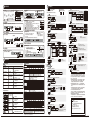
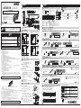
外形寸法図
単位:mm
4.2
10
5.1
104.8 (カバー開時最大)
警告
● 警告表示
しきい値
20.5
PLC など
( 動作電流
1mA 以下)
0V
青③
*1 形 E3NX-FA21/FA7TW のみ
*2 形 E3NX-FA21 のみ
*3 形 E3NX-FA51/FA9TW/FA54TW のみ
2-3
● 2点チューニング
PLC など
( 動作電流
3mA 以下)
黒④
( 制御出力1)
設定完了
受光量設定:ボタン押下時の受光量を "0" に調整します。
しきい値設定:ボタン押下時の約 7% の受光量に設定します。
反射形 :
検出体なし
状態
1pnt
検出体
ただし、背景物体の影響を受けやすくなります。
0
0
3秒以上長押し
● フルオートチューニング
受光量設定:ボタン押下中の最大受光量をパワーチューニングレベルに調整します。
しきい値設定:ボタン押下中の最大受光量と最小受光量の中間に設定します。
1500
9999
橙②
検出体を通し終えたら指を離す
7秒以上長押し
設定完了
検出体
④検出体の位置を決めたい
● 位置決めチューニング
受光量設定:検出したい位置の受光量をパワーチューニングレベルの半分の受光量に調整します。
しきい値設定:検出したい位置の受光量と同じ値に設定します。
検出体
なし状態
検出したい
位置
1pnt 9999
9999
指を離すことで"2Pnt"を表示
■DIN レールからの取外し
2
1
● パーセントチューニング
■連結して使用する場合
(1)アンプユニットを1台ずつDINレールに取り付けま
す。
通信コネクタが密着するまで、アンプユニットをスラ
イドさせます(矢印3)
(2)振動で離れないように、別売のエンドプレート(形
PFP-M)でアンプをしっかりとはさんでください。
(矢印4)
(3)ドライバでエンドプレートのネジを締めてください。
(矢印5)
受光量設定:検出体がない状態の受光量をパワーチューニングレベルに調整します。
しきい値設定:上記設定された受光量 ×(1+パーセントチューニングレベル)に設定します。
パーセントチューニング設定
ON
DINレール
3
検出体なし状態
⑥ほこりや汚れによる受光量変化を元に戻したい
4
5
ファイバユニットの取付け
2
ファイバカッタ
形E39-F4
(ファイバユニットに付属)
(1) ファイバをファイバーカッタの穴に挿入します。
(2) 刃を一気に押し下げて切断します。
細径ファイバユニット用
穴2コ
細径ファイバ用アタッチメント
形E39-F9
標準ファイバユニット 1
(φ2.2㎜)
用穴3コ
(3) ファイバユニット挿入口にファイバユニットを確実に奥まで差し込みます。
設定完了
1秒以上長押し
● パワーチューニング
受光量設定:ボタン押下時の受光量をパワーチューニングレベルに調整します。
しきい値設定:変更されません。
+
2
1秒以上両押し
チャンネル切替(2出力タイプ:E3NX-FA21、E3NX-FA51、E3NX-FA7TW、E3NX-FA9TW、形E3NX-FA54TW)
■OUT 選択表示灯が切替わり、設定内容を切替えます。
1.[検出モード]で[MODE]ボタンを 1 秒間押します。
2. OUT 選択表示灯 ( 出力 1/ 出力 2) が切替わります。
[出力1]
ファイバユニット
●スマートチューニングエラー
エラー名 / 表示 / 原因
ニアエラー
err
1 点目と 2 点目の受光量差が
小さすぎる状態です。
オーバーエラー
err
OUT選択表示灯(出力1)
ローエラー
カバー
err
1
受光量が小さい状態です。
(4) ロックレバーを元の方向に戻して、ファイバユニットを固定します。(ロック)
3
設定完了
発生チューニング種別
[出力2]
[検出モード]で、[MODE]ボタン1秒間押下
OUT選択表示灯(出力2)
2-5
対応方法
・検出機能を応答時間が遅いモードに変更ください。
2 点チューニング
(透過形)
フルオートチューニング ・投受光間距離を狭めてください。
全て
受光量が大きい状態です。
ロックレバー
ロック
解放
4
2-4
反射形の場合は、検出体がある状態にて実施してください。
位置決めチューニング実施後の場合、透過形・反射形ともに検出体あり
の状態で実施してください。
1500
検出体なし状態
(2) ロックレバーを起こします。
(解放)
設定完了
パーセントチューニング ON 設定時は、
パワーチューニングのみ実行できます。
その他のチューニングは実行できません。
per 1500
「⑤ 詳細設定編」
押しながらネジを締めてください。
■ファイバカッタの使用方法
3秒以上長押し
⑤透明体や小物を検出したい(受光量比率でしきい値を設定したい)
ファイバユニット挿入部側のツメ
(1) 本体を矢印 1 の方向へ押します。
(2) (1) をしながら矢印 2 の方向へ持ち上げます。
設定完了
"FULL"が表示されたら指を離す
③ラインを止めずに移動する検出体で調整したい
(1) ファイバユニット挿入部側のツメをレールにかけます。
(2) フックがカチッと音がするまで押し込みます。
・細径ファイバユニットを取り付けるには、アタッチメン
ト(形 E39-F9)が必要です。
(アタッチメントは、適用ファ
イバユニットに付属しています。)
・同軸反射形ファイバユニットを本体に取り付ける場合、
単芯ファイバを取り付け穴の上 ( 投光 ) 側に、複芯ファイ
バを下 ( 受光 ) 側に取り付けてください。
2pnt 2500
検出体なし状態
指を離すことで"2Pnt"を表示
DC10-30V
茶①
検出体あり/なしの順番は逆でも設定可能です。
1pnt 9999
検出体あり状態
透過形 :
検出体あり状態
アンプユニットの取付け
(1) カバーを開きます。
受光量設定:1 点目 /2 点目の大きい方をパワーチューニングレベルに調整します。
しきい値設定:1 点目 /2 点目の受光量の中間に設定します。
● 最大感度チューニング
0V
青③
*4 形 E3NX-FA51 のみ
*①,②,③,④は、M8 コネクタタイプのピン端子
■ファイバユニットの取付け
出力切替
【L/D】ボタン
3 秒以上長押しすることで、設定モード 1 回押すことで
入光時 ON(L)/ しゃ光時 ON(D) を切替
と検出モードを切替えます。
・1 秒間押下で出力切替(2 出力時) えます。[L/D] 表示灯の点灯が切替わります。
①検出体のあり/なしを検出したい
0V
青③
最大連結可能台数は 30 台です。
振動等がある場合は、アンプユニット単体でもエンド
プレートを使用してください。
検出体
L/D
スマートチューニング【簡単感度調整】
■DIN レールへの取付け
1-4
緑デジタルのしきい値が
変わります。
負荷
・アンプユニット 1台 ・取扱説明書(本書) 各1部(日本語 英語 中国語)
黒④
( 制御出力1)
反射形:検出体ありで ON させる場合は、「入光時 ON」に設定します。
[L/D 表示灯 ] の が点灯します。
UP
MODE
検出体
「③ 便利な設定編」
受光量
モード / OUT 切替
しきい値の微調整
【UP/DOWN】ボタン 【MODE】ボタン
チューニングを実施し、[ST 表示灯 ]
が点灯します。
■形 E3NX-FA9/FA54(PNP タイプ )
DC10-30V
透過形:検出体ありで ON させる場合は、「しゃ光時 ON」に設定します。
[L/D 表示灯 ] の が点灯します。
MODE
②ほこりや汚れに強くしたい
負荷
負荷
パッケージ内容の確認
桃 *4
0V
橙②
UP/DOWN
白デジタル
PLC など
( 動作電流
3mA 以下)
黒④
( 制御出力1)
橙② *3
( 制御出力 2)
PLC など
( 動作電流
1mA 以下)
センサ主回路
・コードの延長は100m以下としてください
(Sマーク認証は10m未満となります)
。延長には0.3mm2以上のコードを
ご使用ください。
・コード部に加わる力は下記の値以下としてください。
引っ張り40N以下、
トルク0.1N・m以下、押圧20N以下、屈曲29.4N以下
・ファイバユニットをアンプユニットに固定した状態で、
引っ張り、圧縮、
ねじりなどの無理な力を加えないでください。
・保護カバーは必ず装着した状態で使用してください。誤動作の危険があります。
・電源投入直後は使用環境に応じて受光量/測定値が安定するまで時間がかかる場合があります。
・電源投入後、200ms以上経過後に検出が可能となります。
・モバイルコンソール形E3X-MC11、形E3X-MC11-SV2、形E3X-MC11-Sは使用できません。
・形E3C/E2C/E3Xとは相互干渉防止機能が働きません。
・過大なセンサ光が入光した場合は、相互干渉防止機能が十分に機能せずに誤動作する場合があります。
その
場合はしきい値を大きく設定してください。
・通信ユニット形E3X-DRT21-S、形E3X-CRT、形E3X-ECT、形E3NWは使用できません。
・万が一、異常を感じたときには、
すぐに使用を中止し、電源を切った上で、
当社支店・営業所までご相談ください。
・清掃にはシンナー、
ベンジン、
アセトン、灯油類は使用しないでください。
茶①
感度設定
【 】ボタン
S.TUNE
DC10-30V
茶①
過電流保護回路
保護用シール
連結用電源端子
センサ主回路
橙 *1
( 制御出力 2)
負荷
・DINレールへの取り付け時には、
カチッと音がするまで取り付けてください。
・コネクタタイプを使用される場合、感電や短絡防止のため、使用しない連結用電源端子には保護用シール
(コネ
クタ:形E3X-CNシリーズに付属)
を貼ってください。
センサ主回路
使用上の注意
DC10-30V
黒
( 制御出力1)
青
1-3
①
③
<M8 コネクタタイプ >
10
■形 E3NX-FA41/FA51/FA8/FA9TW/FA54TW
(PNP タイプ )
■形 E3NX-FA7/FA24(NPN タイプ )
過電流保護回路
以下に示す項目は安全を確保するうえで必要なことですので必ず守ってください。破損・発火の恐れがあります。
・下記の設置場所では使用しないでください。
①直射日光が当たる場所
②湿度が高く、結露する恐れがある場所
③腐食性ガスのある場所
④振動や衝撃が定格の範囲を超える場所
⑤水・油・化学薬品の飛沫がある場所
⑥蒸気の当たる場所
⑦強電界・強磁界のある場所
・引火性、爆発性ガスの環境では使用しないでください。
・定格を超える周囲雰囲気・環境では使用しないでください。
・操作や保守の安全性を確保するため、高圧機器や動力機器から離して設置してください。
・高圧線、動力線と本製品の配線は別配線としてください。同一配線あるいは同一ダクトにすると誘導を受け、誤
動作あるいは破損の原因になることがあります。
・負荷は定格以下でご使用ください。破損、発火の恐れがあります。
・負荷を短絡させないでください。破損、発火の恐れがあります。
・負荷の接続を正しく行ってください。
・電源の極性など、誤配線をしないでください。
・ケースが破損した状態で使用しないでください。
・火傷の恐れがあります。使用条件(周囲温度、電源電圧、他)
によってはセンサ表面温度が高くなります。操作
時や清掃時にはご注意ください。
・センサ設定時は、装置を停止していただく等、安全をご確認された上で行ってください。
・配線を着脱するときは、
必ず電源を切ってから行ってください。
・本体の分解、修理・改造をしないでください。
・廃棄するときは、産業廃棄物として処理してください。
・水中、降雨中、
および屋外での使用は避けてください。
・UL規格認証について
エンハンストUL認証マークを表示している製品のみが、ULによるリスティング認証を取得しています。Class2回
路で使用することを前提としています。米国、
カナダでご使用の際は、入力/出力とも同一のClass2回路に接続
してください。過電流保護の最大電流使用定格は、2Aです。
オープンタイプとして評価されています。
エンクロー
ジャー内に設置してください。
20.5
過電流保護回路
茶
桃 *2
安全上の要点
71.8
< 省配線コネクタタイプ >
④
②
入出力段回路図
負荷
故障や発火の恐れがあります。
定格電圧を超えて使用しないでください。
破裂の恐れがあります。
AC電源では絶対に使用しないでください。
16
< コード引き出しタイプ >
負荷
センサ主回路
安全を確保する目的で直接的または間接的に人体を検出する用途に本製
品は使用できません。人体保護用の検出装置として本製品を使用しない
でください。
9.4
37.9
■形 E3NX-FA11/FA21/FA6/FA7TW
(NPN タイプ )
過電流保護回路
警告
キーロック
SmartTuning 実行時に点灯します。
ゼロリセット
( ) 内の寸法は関連部品との寸法になります。
カバーを 170 度以上傾けると外れる事があります。
1-2
[ST 表示灯:青色 ]
緑デジタル
光通信部
ボタンを押します。
L/D
設定初期化
L/D
16.5
DINレール別売 PFP-□N
正しい取扱いをしなければ、この危険のために、軽傷・中程度
の傷害を負ったり、万一の場合には重傷や死亡に至る恐れがあ
ります。また、同様に重大な物的損害をもたらす恐れがありま
す。
入光時 ON(L)/ しゃ光時 ON(D) の設定状態を表示します。
DynamicPowerControl 機能有効時に点灯します。
12.7
4.8
[DPC 表示灯:緑色 ]
出力切替方法
+:同時押し
ソリューション
ビューワ
4.3
2012-2014 All Rights
5.7
© OMRON Corporation
* 5 3 3 9 0 0 5 - 0 H *
Reserved.
(1/3)
形 E3NX-FA21、形 E3NX-FA7TW
形 E3NX-FA51、形 E3NX-FA9TW
形 E3NX-FA54TW
出力 ON 時に点灯します。
φ4
.4
2-φ2
[L/D 表示灯:橙色 ]
[OUT 表示灯:橙色 ]
170° (カバー開時最大)
2-2
操作・表示早見表
[OUT 選択表示灯:橙色 ]
[OUT 表示灯:橙色 ]
147.1(カバー開時最大)
細径ファイバ用
アタッチメント
( 形 E39-F9) 装着時
4.5
このたびは、本製品をお買い上げいただきまして、
誠にありがとうございます。
ご使用に際しては、次の内容をお守りください。
・電気の知識を有する専門家がお取り扱いください。
・この取扱説明書をよくお読みになり、十分にご理解のうえ、
正しくご使用ください。
・この取扱説明書はいつでも参照できるよう大切に保管して
ください。
27.1
6.9
10
取扱説明書
設定編
2-1
21.7
(13)
1-1
2
12.7
E3NX-FA□□シリーズ
設置編
5.2
形
1
37
33.5
5.7
3.4
スマートファイバアンプ
最大感度チューニング
以外
・ファイバヘッドを検出体に近づけてください。(反射形)
・投受光間距離を広げてください。(透過形)
・ファイバヘッドを検出体から遠ざけてください。 (反射形)
・細径ファイバを使用してください。
・投受光間距離を近づけてください。(透過形)
・ファイバヘッドを検出体に近づけてください。(反射形)
しきい値の微調整
ボタンで調整します。 しきい値が大きくなります。
UP/DOWN
単芯
複芯
出力 2 でも、Light-ON/Dark-ON は切替え可能です。
(2-2 参照)
しきい値が小さくなります。
長押しにて高速で調整できます。
E3NX-FA□□シリーズ
3
5
便利な設定編
ほこりや汚れで受光量が変化しても安定して検出したい場合
● DPC機能
DPC 機能有効時は DPC 表示灯が点灯します
DPC 機能は透過形 / 回帰反射形での使用をおすすめします。
スマート
チューニング
設定
モード
実行
選択
DPC 機能
ON
受光量
内部受光量
スマートチューニングがエラーだった場合 / 最大感度
チューニングを実行した場合 / 位置決めチューニングの
1 点目が小さい場合 / エリア検出モードの場合は DPC 機能が無効となります。
時間
[rst]
3秒以上両押し
[
UP/DOWN
MODE
]
rst
UP/DOWN
MODE
[
UP/DOWN
yes ]
2000 9999
MODE
[rst user]
UP/DOWN
MODE
誤操作を防ぎたい場合
実行 / 解除(同手順)
通過時間 受光量差
(ms or μs)
*UP/DOWN どちらかを押してください。
STND
応答時間 250μs
1ms
1(基準) 1倍
光量
(受光量例)
500
HS 高速モード
UP/DOWN
500
stnd
STND 標準モード
4000
GIGA ギガモード
GIGA
16ms
8倍
shs
SHS 最速モード
std
しきい値 /
受光量
125
トラブル
原因
%ff
dpc
DPC OFF
UP/DOWN
表示部に何も表示し
ない
電源が入っていないか、 配線及びコネクタ接続の見直し、電源電圧・電源容量の
断線しています。
見直しを行ってください。
「1-2 入出力段回路図」
デジタル表示に何も
表示しない
エコ機能が ON になっ
ています。
しきい値が最小でも
検知・検出できない
検出機能が光量の小さい
GIGA モードに設定すると、投光パワーが大きくなり
モードに設定されています。 受光量が増加します。
ほこりや汚れが影響
「⑤ 詳細設定編」
しています。
相互干渉等が影響して アンプの連結状態を確認して、
電源を再投入してください。
います。
「1-3 アンプユニットの取り付け」
OUT 表示灯が点滅する
エコ機能を OFF してください。
「⑤ 詳細設定編」
受光量がー(マイナス) ゼロリセット機能が有効
になっています。
ゼロリセットを解除してください。
設定が分からなく
なってしまった
設定初期化を行ってください。
「③ 便利な設定編」
表示になる
ー
「③ 便利な設定編」
● エラー表示
エラー名 / 表示
DPCエラー*
2 0 0 0 4000
EEPROM タイムアウトエラー
e-me
01
EEPROM チェックサムエラー
e-me
02
ロックオン
負荷短絡検知エラー
e-st
* DPC表示灯が点滅します。
原因
対応方法
ファイバユニットの検出面などを拭き取り、受光量を復帰さ
受光量がほこりや
汚れにより低下して せ、再度スマートチューニングしてください。
います。
「2-3 スマートチューニング」
内部データの読み
出し / 書き込みに
失敗しています。
電源を再投入してください。復帰しない場合は、設定初期化
を行ってください。
内部データの読み
出し / 書き込みに
失敗しています。
電源を再投入してください。復帰しない場合は、設定初期化
を行ってください。
「③ 便利な設定編」
「③ 便利な設定編」
キーロックが有効に キーロックを解除してください。
なっています。
「③ 便利な設定編」
制御出力に過電流が 配線及びコネクタ接続を見直してください。
流れています。
「1-2 入出力段回路図、4-2 定格 / 仕様」
*1.入力に関する詳細は、以下となります。
NPN タイプ
PNP タイプ
有接点入力(リレー、スイッチ)
ON 時 :0V に短絡(流出電流:1mA 以下)
OFF 時:開放、または Vcc に短絡
ON 時 :Vcc に短絡(吸込電流:3mA 以下)
OFF 時:開放、または 0V に短絡
通常
ボタン押下後
f ----
UP/DOWN
タイムオフ
UP/DOWN
MODE
(b) オンディレイ
入光時
オフディレイタイマ
しゃ光時
検出時間が短く、PLC 入光時 ON
(a)
で検出ができない場合、 ON OFF
ON
出力 ON を保持します。しや光時
ON OFF
しきい値
通過時間 (ms or μs)
オンディレイタイマ
(b) 検出してから出力 ON
を遅らせます。
500m 63
cfdr
ch
bar
150p
(b)
8000 2000
(c)
(d)
(d) ピーク時の受光量
3000
(f)
2000 9999
(c) ワンショット
T
T
入光時
しゃ光時
入光時 ON
ON OFF
T
T
しや光時 ON
ON OFF
オンオフディレイタイマ
オフディレイタイマと
(d)
オンディレイタイマの
両方を設定できます。
エコ機能 OFF
UP/DOWN
エコ機能 ON
ec%
エコ機能 LO
ec%
%n
l%
T
T
Eco on
表示灯 ( 緑デジタル , 白デジタル ) が消灯します。
ボタン操作すると、約 10 秒間点灯した後、消灯します。
Eco Lo
ボタン操作すると、約 10 秒間点灯した後、
表示灯 ( 緑デジタル , 白デジタル ) が低輝度で点灯します。
入光時
しゃ光時
入光時 ON
ON OFF
しや光時 ON
ON OFF
Ta
Tb
Ta
Tb
MODE
15. ヒス幅
(参考値)
hstd
標準設定
ヒステリシス幅を初期値で設定します。判定出力が境界付近で
37
不安定にならないようしきい値にヒステリシス幅を設けています。
UP/DOWN
husr
37
husr
37
ユーザ設定
「husr」のメニューで
MODE
ボタンを押した後、 UP/DOWN
ボタンにてヒステリシス幅を設定可能です。
(0∼9999、1刻み)
ユーザ設定 (2 出力タイプで表示されます。)
チャタリングが起こる可能性があるので
出力の安定を確認してご使用ください。
MODE
16. 外部入力の EEPROM への書込
] の場合
A
機能選択 [
%n
ON
] の場合
ban
MODE
UP/DOWN
BANK1
2
ban
BANK2
3
ban
BANK3
ban
BANK4
%n
UP/DOWN
ptun
%ff
パワーチューニング調整 OFF
MODE
)
8. パーセントチューニング 透明体や微小物体を検出したい場合(2 出力タイプは 2 出力分が表示されます。
per
パーセント
チューニング
OFF
%ff
UP/DOWN
「
%n
per
EEPROM に書き込まれなくなり、EEPROM が
寿命(書込 100 万回)に達するのを防ぎます。
UP/DOWN
3秒以上長押しで検出モードに移行
ご承諾事項
MODE
ptun
A
4
7. パワーチューニング ON/OFF 設定 チューニング時の光量調整を ON/OFF したい場合
パワーチューニング
調整 ON
「oFF」で外部入力により変更された設定が
UP/DOWN
OFF
6. BANK 切替 選択したバンク毎に設定値を保存したい場合
」のメニューで
ボタンを押した後、
MODE
ボタンにてパーセントチューニングレベルを
設定可能です。(-99% ∼ 99%、1%刻み、初期値 -6%)
パーセントチューニング ON
当社商品は、一般工業製品向けの汎用品として設計製造されています。従いまして、次に
掲げる用途での使用を意図しておらず、
お客様が当社商品をこれらの用途に使用される際
には、当社は当社商品に対して一切保証をいたしません。
ただし、次に掲げる用途であって
も当社の意図した特別な商品用途の場合や特別の合意がある場合は除きます。
(a) 高い安全性が必要とされる用途
(例:原子力制御設備、燃焼設備、航空・宇宙設備、鉄
道設備、昇降設備、娯楽設備、医用機器、安全装置、
その他生命・身体に危険が及び
うる用途)
(b) 高い信頼性が必要な用途
(例:ガス・水道・電気等の供給システム、24時間連続運転
システム、決済システムほか権利・財産を取扱う用途など)
(c) 厳しい条件または環境での用途
(例:屋外に設置する設備、化学的汚染を被る設備、
電磁的妨害を被る設備、振動・衝撃を受ける設備など)
(d) カタログ等に記載のない条件や環境での用途
*(a)から(d)に記載されている他、本カタログ等記載の商品は自動車
(二輪車含む。以下同
じ)
向けではありません。自動車に搭載する用途には利用しないで下さい。自動車搭載
用商品については当社営業担当者にご相談ください。
*上記は適合用途の条件の一部です。当社のベスト、総合カタログ、データシート等最新版
のカタログ、
マニュアルに記載の保証・免責事項の内容をよく読んでご使用ください。
インダストリアルオートメーションビジネスカンパニー MODE
●製品に関するお問い合わせ先
お客様相談室
9. 出力 1 モード 出力 1 の出力モードを変更したい場合
std
通常検出モード
0120-919-066
UP/DOWN
area
クイック
オムロン
携帯電話・PHS・IP電話などではご利用いただけませんので、
下記の電話番号へおかけください。
エリア検出モード
電話
055-982-5015(通話料がかかります)
■営業時間:8:00∼21:00 ■営業日:365日
MODE
10. 出力 2 モード 出力 2 の出力モードを変更したい場合
アラーム出力モード: ボタンを押した後、 ボタンにて
MODE
std
通常検出モード
(0P∼100P、1P 刻み、初期値 50P)
UP/DOWN
アラーム出力モード
B
UP/DOWN
警報出力レベルを設定できます。
alrm
形 E3NX-FA11
形 E3NX-FA6
形 E3NX-FA21 形 E3NX-FA7 形 E3NX-FA24 形 E3NX-FA7TW 形 E3NX-FA41
形 E3NX-FA8
形 E3NX-FA51 形 E3NX-FA9 形 E3NX-FA54 形 E3NX-FA9TW 形 E3NX-FA54TW
電源電圧 10V-30V 時
電源電圧 10V-30V 時
通常モード:1080mW 以下(電源電圧 30V 時 消費電流 36mA 以下 / 電源電圧 10V 時 消費電流 108mA 以下) 通常モード:1,230mW 以下(電源電圧 30V 時 消費電流 41mA 以下 / 電源電圧 10V 時 消費電流 123mA 以下)
省電力 ECO:880mW 以下(電源電圧 30V 時 消費電流 28mA 以下 / 電源電圧 10V 時 消費電流 88mA 以下) 省電力 ECO:1,030mW 以下(電源電圧 30V 時 消費電流 33mA 以下 / 電源電圧 10V 時 消費電流 103mA 以下)
エコ機能 LO:980mW 以下(電源電圧 30V 時 消費電流 32mA 以下 / 電源電圧 10V 時 消費電流 98mA 以下) エコ機能 LO:1,130mW 以下(電源電圧 30V 時 消費電流 37mA 以下 / 電源電圧 10V 時 消費電流 113mA 以下)
MODE
受光量が表示されます。
%ff
ec%
(d) オンオフディレイ
入光時
ワンショットタイマ
しゃ光時
検出体の大きさがばら 入光時 ON
(c)
ON OFF
つく場合でも、一定
しや光時 ON
時間出力します。
ON
OFF
緑デジタルにしきい値、白デジタルに
MODE
受光量差
機能選択 [
3500 3000
(e)
表示が反転します。
UP/DOWN
14. エコ機能 消費電力を低減したい場合
MODE
*3. チューニングしても台数に変更はありません。
ファイバ⇔レーザなどの異なるアンプでの相互干渉はアンプ間の仕様上の最小台数になります。
*4. 連結台数が11台以上の場合、周囲温度範囲が50℃未満となります。
p-b
(a)
反転
ボタンにてタイマ時間を設定可能です。
(1∼9999ms、
1ms刻み、初期値10ms)
h
%n-d
(a) オフディレイ
*1-1 外部入力でチューニングまたはパワーチューニングを選択した時のみ、ON/OFF共に25ms以上。
*2. 消費電力
per
%ff
(2 出力タイプは 2 出力分が表示されます。
)
4. タイマ機能 出力のタイマ時間を設定したい場合 無接点入力(トランジスタ)
入力時間 *1-1
ON 時 :1.5V 以下(流出電流:1mA 以下)
OFF 時:Vcc-1.5V ∼ Vcc(漏れ電流:0.1mA 以下) ON:9ms 以上
ON 時 :Vcc-1.5V ∼ Vcc(吸込電流:3mA 以下) OFF:20ms 以上
OFF 時:1.5V 以下(漏れ電流:0.1mA 以下)
実行 解除
ゼロリセット 3s 未満 3s 以上
MODE
MODE
NPN 出力 形 E3NX-FA11 形 E3NX-FA6 形 E3NX-FA21 形 E3NX-FA7 形 E3NX-FA24 形 E3NX-FA7TW 形式
PNP 出力 形 E3NX-FA41 形 E3NX-FA8 形 E3NX-FA51 形 E3NX-FA9 形 E3NX-FA54 形 E3NX-FA9TW 形 E3NX-FA54TW
制御出力数
1
1
2
1
1
2
2
外部入力数 *1
1
1
1
接続方式
コード引き出しタイプ 省配線コネクタタイプ コード引き出しタイプ 省配線コネクタタイプ M8 コネクタタイプ 省配線コネクタタイプ M8 コネクタタイプ
光源(発光波長)
赤色 4 元素発光ダイオード(625nm)
電源電圧
DC10 ∼ 30V リップル (p-p)10% 含む
消費電力 *2
電源電圧 24V 時
電源電圧 24V 時
通常モード:960mW 以下(消費電流 40mA 以下) 通常モード:1080mW 以下(消費電流 45mA 以下)
エコ機能 ON:720mW 以下(消費電流 30mA 以下) エコ機能 ON:840mW 以下(消費電流 35mA 以下)
エコ機能 LO:840mW 以下 ( 消費電流 35mA 以下) エコ機能 LO:960mW 以下 ( 消費電流 40mA 以下)
負荷電源電圧:DC30V 以下、オープンコレクタ出力形(NPN/PNP 出力 形式によって異なります)
制御出力
負荷電流:1∼3 台連結時 100mA 以下、4 台以上連結時 20mA 以下
残留電圧:NPN 出力 2V 以下、PNP 出力 2V 以下
オフ状態電流:0.1mA 以下
保護回路
電源逆接保護、出力短絡保護、出力逆接続保護
最大連結台数
30 台
相互干渉 最速モード (SHS) 0 台 注)検出機能を最速モードに選択した場合は、相互干渉防止機能は無効となります。
高速モード (HS) 10 台
防止 *3
標準モード (Stnd) 10 台
ギガモード (GIGA) 10 台
バンク切替設定
BANK1∼4 から選択可能
APC(オートパワーコントロール) あり(常時有効)
使用周囲照度
白熱ランプ:20,000lx 以下、太陽光:30,000lx 以下
周囲温度範囲 *4
動作時:1 ∼ 2 台連結時:-25℃∼ +55℃、3 ∼ 10 台連結時:-25℃∼ +50℃、
11 ∼ 16 台連結時:-25℃∼ +45℃、17 ∼ 30 台連結時:-25℃∼ +40℃
保存時: -30 ∼ +70℃
(ただし、氷結、結露しないこと)
周囲湿度範囲
動作時・保存時:上記周囲温度範囲にて、各 35 ∼ 85%RH(ただし、結露しないこと)
高度
2000m 以下
設置環境
汚損度 3(IEC60947-1 による)
絶縁抵抗
20MΩ以上(DC500V メガにて)
耐電圧
AC1,000V 50/60Hz 1min
振動(耐久)
10 ∼ 55Hz 複振幅 1.5mm X、Y、Z 各方向 2h
衝撃(耐久)
500m/s2 X、Y、Z 各方向 3 回
質量
ケーブル長 2m 約 115g/ 約 75g 約 60g/ 約 20g 約 115g/ 約 75g 約 60g/ 約 20g 約 65g/ 約 25g 約 60g/ 約 20g 約 65g/ 約 25g
(梱包 / 本体) ケーブル長 5m 約 200g/ 約 160g 約 200g/ 約 160g 材質
ケース、カバー : ポリカーボネート(PC)ケーブル被覆:PVC
UP/DOWN
13. 反転表示 アンプを反対に設置したい場合
%n
dpc
DPC ON
定格/仕様
0rst
3. DPC 機能 受光量が変化しても安定して検出したい場合
9999
対応方法
ゼロリセット
(f) しきい値 / 通過後の受光量 (e)ch 番号と受光量
5. パワーチューニングレベル 受光量目標値 ( パワーチューニングレベル ) を変更したい場合
ボタンにてパワーチューニングレベルを設定可能です。
UP/DOWN
(100∼9999、1刻み、
初期値9999)
● トラブルシューティング
BANK 切替 OFF:1、ON:2
(a) しきい値に対する受光量 (b) 入光時のピーク受光量 (c) バー表示
としゃ光時のボトム受光量
の余裕度
MODE
4-2
投光 OFF
12. デジタル表示 検出モード時のデジタル表示を用途に応じて変更したい場合
SHS
1 出力タイプ 30μs、2 出力タイプ 32μs
0.25 倍
MODE
fd
通過時間
(ms or μs)
パワーチューニング
最大感度 3秒以上 ー
チューニング 7秒未満
フルオート 7秒以上 ー
チューニング
位置決め 3秒未満 3秒以上
チューニング
MODE
hs
通過直後
0
ptun
ゼロリセットの実行 / 解除は、入力を OFFしたタイミングとなります。
MODE
1. [MODE] ボタン +[L/D] ボタン 3 秒以上両押しで [SoLU on]
0m
tune
UP/DOWN
2. 検出機能 光量および応答時間を変更したい場合 検出機能 HS
● ソリューションビューワ
3秒以上両押し
チューニング
1点目 2点目
チューニング選択時(in tUnE)の 2点 3秒未満 3秒未満
信号入力時間はボタン入力時間と同様になります。 チューニング
詳細設定
2000 1000
に設定します。設定解除の場合は [MODE] ボタン +
[L/D] ボタン 3 秒以上両押しで [SoLU oFF] に設定します。
ワークを通過させます。
通過時間 / 受光量差が表示します。
[MODE] ボタン +[L/D] ボタン 3 秒以上両押しで設定モードを抜けます。 受光量差
UP/DOWN
func
ワークが検出可能かを判断したい場合
2.
3.
4.
● キーロック ボタン操作を全て無効にします。
トラブルシューティング
基本設定
[設定モード]ではチェンジファインダ
が表示されません。
入光時 ON では極大値が、
しゃ光時 ON では極小値が表示されます。
通過前
ユーザーリセット
[rst]
dflt
func
1. [ 設定モード ]→[ デジタル表示 ] で [diSP CFdr] に設定します。
2. [MODE] ボタン 3 秒以上押しで設定モードを抜けます。
3. ワークを通過させます。
4. 通過した時の受光量(極大値 or 極小値)を 0.5 秒、白デジタルに保持表示します。
MODE
%ff
入力 OFF
1. 機能選択 6 ∼ 16 を有効にしたいしたい場合
Hi
● チェンジファインダ
ユーザーセーブ
4-1
3秒以上両押し
高速な検出体通過時の受光量を見たい場合
MODE
]
設定モードでは以下の機能設定ができます。
機能遷移に表示している内容は、工場出荷時の内容です。
B
11. 外部入力 外部入力の種別を変更したい場合(外部入力タイプのみ搭載)
A
[MODE] ボタン 3 秒以上押しで設定モードを抜けます。
2. [検出モード]にて [MODE] ボタンを短押しし、OUT1 HIGH と OUT1 LOW を表示させます。
Lo
緑デジタルに HIGH と LOW が表示されます。
3. HIGH/LOW しきい値に対して、それぞれ
[S.TUNE]ボタンを押して、スマートチューニングを行います。
入光時 ON ON
制御出力 OFF
パーセントチューニング時:下記のようにしきい値が設定されます。
HIGH:3. の受光量+3. の受光量 × パーセントチューニングレベルの絶対値 しゃ光時 ON ON
制御出力 OFF
LOW:3. の受光量−3. の受光量 × パーセントチューニングレベルの絶対値
● 設定保存 / 読み出し
メンテナンス編
DPC 機能 / スマートチューニングを
実行すると、ゼロリセットは解除されます。
3秒以上両押し
● エリア検出モード
設定を保存したい / 読み出したい場合
[
MODE
6000 4000
1. [設定モード]→[ 出力 1 モード ]→[ エリア検出モード ] を選択します。
rst
4
0
出力 1/ 出力 2 別に設定する項目は
出力別に OUT 選択表示灯が表示します。
ボタンを 3 秒以上長押しすると設定モードとなります。
受光量がエリア内にあるときに出力したい場合
設定内容を初期化し、工場出荷時の状態に戻します。
3秒以上両押し
実行によりしきい値も連動します。
しきい値の下限は -1999 です。
解除
2000
内部受光量の変化を
補正し表示受光量を
一定にします。
表示受光量
設定を初期化したい場合
● 設定初期化
● ゼロリセット
実行
しきい値
「② 設定編」
受光量表示を 0 にしたい場合
詳細設定編
err
エラー出力モード
300ms のオンディレイがかかります。
エラー出力モード:DPC エラー、EEPROM エラー、負荷短絡検知
エラーが発生した時、出力します。
●FAXやWebページでもお問い合わせいただけます。
FAX
055-982-5051 / www.fa.omron.co.jp
●その他のお問い合わせ
納期・価格・サンプル・仕様書は貴社のお取引先、または貴社
担当オムロン販売員にご相談ください。
オムロン制御機器販売店やオムロン販売拠点は、Webページで
ご案内しています。
A v 2 0 1 4 年 7月
E3NX-FA□□シリーズ
WARNING
Warning Indications
6.9
5.2
4.2
10
20.5
9.4
37.9
Brown
①
(13)
12.7
③
Pink *4
Blue③
①
Orange②
0V
*1 E3NX-FA21/FA7TW only
*2 E3NX-FA21 only
*3 E3NX-FA51/FA9TW/FA54TW only
● 2-point Tuning
Through-beam:
Workpiece is present
1pnt 9999
Reflective:
Workpiece is absent
1pnt
1500
Release the button when the workpiece passed through.
Workpiece
Hold for 7 seconds or longer
Setting is Completed
Receiving light setting: Adjusts the receiving light amount to a half of that for the power tuning level with Desirable detection position.
Threshold setting: Set to the same value as the received light amount Desirable detection position.
Slide the Amplifier Unit until the communication connector is
closely attached.(Arrow 3)
(2) Use End Plates (PFP-M: separately sold) at the both
ends of the grouped Amplifier Units to prevent them from
separating due to vibration or other cause.(Arrow 4)
(3) Tighten the screw on the End Plates using a driver.(Arrow 5)
● Percentage Tuning
5
4
● Power Tuning
Fiber Cutter E39-F4
(Provided with
the Fiber Unit)
(2) Press down the blade at a single
Thin-diameter
Fiber Unit Hole x 2
Thin-diameter Fiber
Attachment: E39-F9
Standard Fiber Unit
1
Hole (dia. 2.2 mm) x 3
1
Hold both for 1 sec. or longer
■OUT Selection Indicator switches to switch the settings.
1. Hold the [MODE] button for 1 second in [Measurement Mode].
2. OUT Selection Indicators (Output 1/Output 2) switch.
When mounting a coaxial reflective Fiber Unit, insert the
Single Core
single-core Fiber Unit to the upper hole (Emitter side) and Multi Core
the multi-core Fiber Unit to the lower hole (Receiver side).
Setting is Completed
● Smart Tuning Error
Error / Display / Cause
Near Error
err
The light level difference
between Points 1 and 2 are
extremely small.
Over Error
OUT Selection Indicator (Output 1)
err
Incident light level is too
high.
Low Error
Cover
err
3
Fiber Unit
[Output 2]
Adjustment for a reflective type requires the presence of a workpiece.
Both thru-beam and reflective types require the presence of a workpiece
if the setting is made after position tuning.
1500
+
2-4 Channel switching (2-output type: E3NX-FA21, E3NX-FA51, E3NX-FA7TW, E3NX-FA9TW, and E3NX-FA54TW)
[Output 1]
Lock Lever
Lock
Release
Setting is Completed
Received light intensity setting: Adjust the power tuning level to the received light amount when the button is pressed.
Threshold setting: Not changed.
Workpiece is absent
Tighten the screw while pressing the End Plate.
(1) Insert a Fiber Unit into a fiber cutter hole.
Hold for 1 seconds or longer
⑥Initializing the Light Intensity Level Change Caused by Dust or Dirt
Under environments such as vibration, use an End Plate
even with a single amplifier unit.
2
When percent tuning setting is ON, only power tuning can be performed.
Other tunings cannot be performed.
per 1500
Workpiece is absent
Refer to " Detailed Settings".
Up to 30 Amplifier Units can be joined.
(4) Return the lock lever to the original position and fix the Fiber Unit.(Lock)
Received light intensity setting: Adjusts the light intensity level without the presence of a sensing object to the power tuning level.
Threshold setting: Light intensity level that has been set according to the setting above x (1 + Percentage tuning level)
Percentage tuning setting
ON
3
2
Setting is Completed
⑤Detecting a Transparent or Microscopic Object (Setting a Threshold with Received Light Intensity Ratio)
DIN Track
4
9999
Hold for 3 seconds or longer
Moving the finger off the button displays "2Pnt".
1
(1) Mount the Amplifier Units one at a time onto the DIN track.
(3) Insert the Fiber Unit in the fiber unit hole to the bottom.
Desirable
detection
position
1pnt 9999
Fiber Unit Connection Side Hook
■Joining Amplifier Units
・To mount the thin-diameter Fiber Unit, an attachment
(E39-F9) is required.(The attachment is included with
the applicable Fiber Unit.)
Setting is Completed
Received light intensity setting: Adjust the power tuning level to the maximum received light amount when the button is pressed.
Threshold setting: Set to the middle between the maximum and minimum received light amount values when the button is pressed.
Workpiece
is absent
■Removing from DIN Track
2
(1) Push the unit in the direction 1.
(2) Lift the unit in the direction of arrow 2 while performing step (1).
(2) Raise the lock lever.(Release)
Release the button when "FULL" appears.
9999
● Position Tuning
connection side catch the track.
(2) Push the unit until the hook clicks into place.
(1) Open the cover.
0
④Determining the Workpiece Position
(1) Let the hook on the Amplifier Unit's Fiber Unit
■Mount Fiber Unit
0
Hold for 3 seconds or longer
● Full Auto Tuning
■Mounting on DIN Track
stroke to cut the Fiber Unit.
It will become susceptible to the influence of
background objects.
③Making Adjustment with Moving Workpiece without Stopping the Line
1-3 Mounting the Amplifier Unit
■Use Fiber Cutter
Setting is Completed
Received light intensity setting: Adjust the received light amount to "0" when the button is pressed.
Threshold setting: Received light amount after light amount adjustment when the button is pressed.
*4 E3NX-FA51 only
*①, ②, ③ and ④ are pin terminals of M8 Connector Type
1-4 Mounting Fiber Unit
2pnt 2500
Workpiece is absent
Moving the finger off the button displays "2Pnt".
0V
Blue③
Execution can be done even if the order of workpiece
exists/not exist is reversed.
Received light intensity setting: Adjust to the either higher value of Point 1 and Point 2 power tuning levels.
Threshold setting: Set to the middle between Point 1 and Point 2 received light intensity values.
Workpiece
PLC, etc.
(Operating current
3mA max.)
Black:④
Control Output 1
ON.
2-3 Smart Tuning [Easy Sensitivity Setting]
①Detecting Presence/Absence of Workpiece
● Maximum Sensitivity Tuning
Load
PLC, etc.
(Operating current
1 mA max.)
Sensor Main Circuit
Black:④
Control Output 1
[L/D Indicator] turns
A single press switches between
Light ON/Dark ON. [L/D] Indicator
changes.
long press (3 seconds or longer) of the key. If pressed
and held for 1 second, OUT is switched (2 outputs).
10 to 30 VDC
Brown
Workpiece
Reflective: Set to "Light ON" to turn the
output ON with a workpiece in the detection area.
Output Switch
[L/D] Button
Mode/OUT Switch
Minute Threshold
Adjustment
[MODE]Button
[UP/DOWN] Button Switches between SET mode and RUN mode by a
The green digital value
changes.
L/D
②Increasing Resistance to Dust and Dirt
■E3NX-FA9/FA54(PNP)
Orange②
[L/D Indicator] turns ON.
Refer to " Convenient
Setting Features".
Workpiece is present
0V
Blue③
10 to 30 VDC
Performs tuning and [ST Indicator]
turns ON.
PLC, etc.
(Operating current
3mA max.)
Black:④
Control Output 1
Orange ②*3
Control Output 2
0V
■E3NX-FA7/FA24(NPN)
①
Load
PLC, etc.
(Operating current
1 mA max.)
Pink *2
①
Load
Orange *1
Control Output 2
④
S.TUNE Button
【 】
Workpiece
Through-beam: Set to "Dark ON" to turn the
output ON with a workpiece in the detection area.
MODE
Zero Reset
White Digital
Display
10 to 30 VDC
Brown
Overcurrent Protection Circuit
• Instruction Sheet (this sheet): 1 (Japanese, English and Chinese)
10
10 to 30 VDC
Black:
Control Output 1
②
■E3NX-FA41/FA51/FA8/FA9TW/FA54TW(PNP)
Sensor Main Circuit
Checking the Package Content
Brown
Sensitivity Setting
<M8 Connector Type>
Overcurrent Protection Circuit
Protective Label
Power Supply Connecting Terminal
· The length for the cable extension must be 100 m or less (or less than 10 m for S-mark certified
models).Be sure to use a cable of at least 0.3 mm2 for extension.
· Do not apply the forces on the cord exceeding the following limits:
Pull: 40N; torque: 0.1N·m; pressure: 20N; bending: 29.4N
· Do not apply excessive force such as tension, compression or torsion to the amplifier unit with the fiber
unit fixed to the amplifier unit.
· Always keep the protective cover in place when using the product. Not doing so may cause malfunction.
· It may take time until the received light intensity and measured value become stable immediately after
the power is turned on depending on use environment.
· The product is ready to operate 200 ms after the power supply is turned ON.
· The Mobile Console E3X-MC11, E3X-MC11-SV2 and E3X-MC11-S cannot be connected.
· The mutual interference prevention function does not work when in combination with E3C/E2C/E3X.
· If the unit receives excessive sensor light, the mutual interference prevention function may not work
properly, resulting in malfunction of the unit. In such case, increase the threshold.
· The Communication Unit E3X-DRT21-S, E3X-CRT, E3X-ECT and E3NW cannot be connected.
· If you notice an abnormal condition such as a strange odor, extreme heating of the unit, or smoke,
immediately stop using the product, turn off the power, and consult your dealer.
· Do not use thinner, benzine, acetone, and lamp oil for cleaning.
UP/DOWN
Incident Light
Level
button.
L/D
UP
<Wire-saving Connector Type>
20.5
<Pre-wired Type>
Load
· Be sure to mount the unit to the DIN track until it clicks.
· When using a connector type product, place a protective label (provided with the E3X-CN series) on the
power supply connecting terminals that are not used, to prevent electric shock or short circuit.
16
71.8
Load
PRECAUTIONS FOR CORRECT USE
Turns ON when Smart Tuning is in progress.
Green Digital
Display
4.8 OPTICAL
COMMUNICATION
POSITION
DIN Track SOLD SEPARATELY
PFP-□N
Load
The following precautions must be observed to ensure safe operation of the product. Doing so may cause
damage or fire.
· Do not install the product in the following locations.
(1) Locations subject to direct sunlight
(2) Locations subject to condensation due to high humidity
(3) Locations subject to corrosive gas
(4) Locations subject to vibration or mechanical shocks exceeding the rated values
(5) Locations subject to exposure to water, oil, chemicals
(6) Locations subject to steam
(7) Locations subjected to strong magnetic field or electric field
· Do not use the product in environments subject to flammable or explosive gases.
· Do not use the product in any atmosphere or environment that exceeds the ratings.
· To secure the safety of operation and maintenance, do not install the product close to high-voltage
devices and power devices.
· High-Voltage lines and power lines must be wired separately from this product. Wiring them together or
placing them in the same duct may cause induction, resulting in malfunction or damage.
· Do not apply any load exceeding the ratings. Otherwise damage or fire may result.
· Do not short the load. Otherwise damage or fire may result.
· Connect the load correctly.
· Do not miswire such as the polarity of the power supply.
· Do not use the product if the case is damaged.
· Burn injury may occur. The product surface temperature rises depending on application conditions, such as
the ambient temperature and the power supply voltage. Attention must be paid during operation or cleaning.
· When setting the sensor, be sure to check safety such as by stopping the equipment.
· Be sure to turn off the power supply before connecting or disconnecting wires.
· Do not attempt to disassemble, repair, or modify the product in any way.
· When disposing of the product, treat it as industrial waste.
· Do not use the Sensor in water, rainfall, or outdoors.
· UL Standard Certification
Only the sensors with Enhanced UL Certification Mark are certified by UL. They are intended to be
supplied by a "Class 2 circuit". When used in United States and Canada, Please use the same Class 2
source for input and output.The overcurrent protection current rating is 2A max. They were evaluated as
Open type and shall be installed within a enclosure.
Key Lock
16.5
Blue
Sensor Main Circuit
PRECAUTIONS FOR SAFE USE
[ST Indicator:Blue]
Threshold Level
dia.
4 dia.
2-2.4
1-2 Input/Output Circuit Diagram
Overcurrent Protection Circuit
Never use the product with an AC power supply. Otherwise,
explosion may result.
[OUT Indicator:Orange]
Press
L/D
Solution Viewer
Dimensions in parentheses () indicates the ones with related components.
The cover could come off if it is tilted by 170 degrees or more.
Sensor Main Circuit
Do not use the product with voltage in excess of the rated voltage.
Excess voltage may result in malfunction or fire.
Setting Reset
MODE
Overcurrent Protection Circuit
This product is not designed or rated for ensuring safety of persons
either directly or indirectly. Do not use it for such purpose.
• Amplifier Unit: 1
170° (Max. with the protective cover open)
■E3NX-FA11/FA21/FA6/FA7TW(NPN)
WARNING
[OUT Indicator:Orange]
Turns ON when Dynamic Power Control is
effective.
With an thin-diameter fiber
attachment (E39-F9)
2012-2014 All Rights Reserved.
Indicates a potentially hazardous situation which, if not avoided,
will result in minor or moderate injury, or may result in serious
injury or death.Additionally there may be significant property damage.
[DPC Indicator:Green]
Turns ON when Output is ON.
2-2 Output switching
+ : Press both
Displays Light ON/Dark ON setting.
E3NX-FA21, E3NX-FA7TW
E3NX-FA51, E3NX-FA9TW
E3NX-FA54TW
147.1(Max. with the protective cover open)
5.1
[L/D Indicator:Orange]
[OUT Selection Indicators:Orange]
12.7
* 5 3 3 9 0 0 5 - 0 H *
(2/3)
2-1 Setting and Display Overview
Unit: mm
27.1
4.3
© OMRON Corporation
10
37
33.5
5.7
3.4
Thank you for selecting an OMRON product. This sheet
primarily describes precautions
required in installing and operating the product.
• A specialist who has the knowledge of electricity must treat
the product.
• Please read this manual carefully, and use it correctly after
thoroughly understanding the product.
• Please keep this manual properly for future reference
whenever it is necessary.
21.7
4.5
INSTRUCTION SHEET
2 Settings
1-1 Dimensions
104.8 (Max. with the protective cover open)
E3NX-FA □□Series
1 Installation
5.7
Smart Fiber Amplifier
Press and hold [MODE] for 1 second under [Detection Mode].
OUT Selection Indicator (Output 2)
Incident light level is too low.
Error Origin Tuning Type
2-point Tuning
Full Auto Tuning
All
・Widen the distance between emitter and receiver. (Though-beam model)
・Move the Fiber Head away from the sensing object. (Reflection model)
・Use a thin-diameter Fiber.
Other than maximum ・Make the distance between emitter and receiver closer. (Through-beam model)
・Move the Fiber Head closer to the sensing object. (Reflection model)
sensitivity tuning
2-5 Minute Adjustment of Threshold Level
Press
UP/DOWN
button to adjust
the threshold level.
Light-ON/Dark-ON can be switched with output 2.(Refer to 2-2)
Remedy
・Change the detection function to the mode of slower response time.
・Narrow the distance between emitter and receiver. (Though-beam model)
・Move the Fiber Head closer to the sensing object. (Reflection model)
The threshold level
becomes higher.
The threshold level
becomes lower.
Hold the key for high-speed level
adjustment.
E3NX-FA□□Series
3 Convenient Setting Features
For Stable Detection Regardless of Received Light Intensity Changed due to Dust or Dirt
● DPC Function
Use of the DPC function with through-beam model
or regressive reflection model is recommended.
Smart
Tuning
SET
mode
Run
Refer to "②Settings".
Select
The DPC indicator turns ON
when the DPC function is
effective.
DPC Function
ON
Incident Light
Level
Internal Incident Light
Level
内部受光量
When smart tuning is in error/
maximum sensitivity tuning is executed/
the 1st point of the position tuning is smaller/ area
detection mode, the DPC function is disabled.
[
UP/DOWN
MODE
]
MODE
User Save Function
[
]
UP/DOWN
UP/DOWN
yes ]
[rst]
2000 9999
UP/DOWN
MODE
Preventing Malfunction
Enable/Cancel
(This procedure)
HS
High-speed
Mode
0
* Press either of UP/DOWN.
Passing time Light amount difference(ms or μs)
Problem
Remedy
Check the wiring, connector connection, power supply
voltage and power supply capacity again.
Refer to "1-2 Input/Output Circuit Diagram"
Nothing is shown
on the digital indication.
Eco mode is ON.
Turn OFF Eco mode.
Sensing/Detection
not possible despite
the minimum
threshold level
Detection set to a small
light level mode
Dust or dirt influences
Setting GIGA Mode increases emission power
and light intensity.
The OUT indicator
blinking
Mutual interference
or other reason
Incident light level
displayed in a
negative value
The zero reset function
is enabled.
Check the Amplifier Units mounted in a group and
turn ON the power again.
Refer to "1-3 Mounting Amplifier Unit"
Refer to "
Error Name / Display
DPC Error*
2 0 0 0 4000
EEPROM time-out error
e-me
01
EEPROM checksum error
e-me
02
Lock ON
Load short circuit detection error
e-st
* The DPC indicator blinks.
Refer to "
Detailed Settings".
Detailed Settings".
Cancel the zero reset function.
Refer to "
Convenient Setting Features"
Reset the settings.
Refer to " Convenient Setting Features"
Cause
shs
GIGA Giga Mode
GIGA
16ms
SHS
One Output: 30μs
Two Output: 32μs
x0.25
x8
Remedy
The incident light
level has
deteriorated due
to dust or dirt.
Wipe the dust off the Fiber Unit detection surface or
other relevant areas and recover the original incident
light level. Then, perform Smart Tuning.
Failed internal
data read/out
Turn ON the power again. Reset the settings if the
error is not corrected.
Failed internal
data read/out
Turn ON the power again. Reset the settings if the
error is not corrected.
Refer to "2-3 Smart Tuning "
Refer to " ③Convenient Setting Features"
Refer to " ③Convenient Setting Features"
The key lock
function enabled
Cancel the key lock function.
Over current flowing
to the control output
Check wiring and connector connection again.
Refer to " ③Convenient Setting Features"
Refer to "1-2 Input/Output Circuit Diagram"
and "4-2 Ratings and Specifications"
NPN output
PNP output
Control output
External input *1
Connection method
Model
Light source (Wavelength)
Power supply voltage
Power consumption*2
Control output
Protection circuit
Maximum connectable Units
Super-high-speed mode (SHS)
Number of
units for mutual High-speed mode (HS)
Standard mode (Stnd)
interference
prevention *3 Giga mode (GIGA)
Bank Switch Setting
Auto Power Control (APC)
Ambient illumination
Surrounding air Temperature range*4
Ambient humidity range
Altitude
Installation environment
Insulation resistance
Dielectric strength
Vibration resistance
Shock resistance
Weight
Cable length 2m
(packed state
/sensor)
Cable length 5m
Materials
NPN output
Threshold
/Receiving
light amount
125
SHS Super High-speed Mode
PNP output
%ff
dpc
DPC OFF
2nd point
Less than
3 seconds
-
Less than 3 sec min.
3 seconds
Enable Cancel
Zero reset Less than 3 sec min.
3 seconds
cfdr
(f)Threshold/Light intensity when the
workpiece passes
ch
(e)CH number and
receiving light amount
bar
(a)
150p
(b)
8000 2000
(c)
(d)
3500 3000
(e)
3000
(d)Peak receiving light amount (f)
2000 9999
UP/DOWN
MODE
%n
dpc
DPC ON
13. Inverted Display Mounting Amplifier in Inverted Direction
%ff
Normal
After pressing the
f ----
MODE
button, Use
%n-d
(b)
On-delay Timer
Delays the output ON
after detection.
500m 63
Incident Light
No Incident Light
L-ON ON
OFF
D-ON ON
OFF
Incident Light
No Incident Light
L-ON ON
OFF
(c)One shot
(c)
T
T
T
D-ON ON
OFF
MODE
14. Eco Function Saving Power Consumption
Incident Light
No Incident Light
L-ON ON
OFF
Incident Light
No Incident Light
D-ON ON
OFF
Eco function
OFF
T
Eco function ON
ec%
%n
Ta
Tb
Eco function LO
ec%
l%
Ta
Tb
MODE
15. Hysteresis width (Reference value)
hstd
UP/DOWN
UP/DOWN
T
D-ON ON
OFF
L-ON ON
OFF
%ff
ec%
Light amount difference(ms or μs)
Use
The display reverses.
Threshold and light intensity are displayed on
green digital and white digital respectively.
Reverse
(d)On Off-delay Timer
One-shot Timer
Keeps the output ON for
a specified time regardless
of the workpiece size
variations.
ON/OFF-delay Timer
Sets both OFF-delay Timer
(d)
and On-delay Timer.
T
UP/DOWN
button to set the power tuning level.
h
(b)On-delay Timer
Off-delay Timer
Holds the output ON for
detection by PLC when
the detection time is too
short.
UP/DOWN
(1 to 9999ms in 1ms steps; the initial value: 10ms)
UP/DOWN
(a)
Light amount difference Passing time(ms or μs)
Standard
setting
37
The indicators (green digital and white digital) turn OFF.
They turn ON for approx. 10 seconds and then turn OFF
by button operation.
Eco Lo
They turn ON for approx. 10 seconds and then
the indicators (green digital and white digital) turn ON
with low brightness.
Set the hysteresis width by initial value. Hysteresis width is provided for
threshold to prevent the judgment output from becoming unstable
near the boundaries.
UP/DOWN
husr
37
husr
37
User setting
button to set the power tuning level.
(100 to 9999 in 1 steps; the initial value: 9999)
Eco on
The hysteresis width can be set by pressing the
button in the menu
UP/DOWN
of "husr" and then pressing the
button. (0 to 9999, increments of 1)
MODE
User setting (Displayed on the two-output type)
Be sure to check the stability of outputs
as there is a possibility of chattering.
MODE
Input time *1-1
ON: 9 ms min.
OFF: 20 ms min.
*1-1 Input time is 25ms (ON)/(OFF) only when (in tUnE) or (in PtUn) input is selected.
*2. Power consumption
E3NX-FA11
E3NX-FA6
E3NX-FA41
E3NX-FA8
Power supply voltage 10V to 30V:
Normal mode: 1080mW max.(Power supply voltage 30V: Power consumption 36mA max./
Power supply voltage 10V: Power consumption 108mA max.)
Power saving ECO: 880mW max.(Power supply voltage 30V: Power consumption 28mA max./
Power supply voltage 10V: Power consumption 88mA max.)
Eco function LO: 980mW max.(Power supply voltage 30V: Power consumption 32mA max./
Power supply voltage 10V: Power consumption 98mA max.)
p-b
per
3. DPC Function Stable Detection Regardless of Incident Light Level Change
Threshold
Non-contact input (Transistor)
ON: 1.5 V max. (Outflow current: 1 mA max.)
OFF: Vcc-1.5 V to Vcc (Leakage current: 0.1 mA max.)
ON: Vcc-1.5 V to Vcc (Sink current: 3 mA max.)
OFF: 1.5 V max. (Leakage current: 0.1 mA max.)
UP/DOWN
MODE
(a)Off-delay Timer
E3NX-FA6
E3NX-FA21 E3NX-FA7
E3NX-FA24 E3NX-FA7TW E3NX-FA8
E3NX-FA51 E3NX-FA9
E3NX-FA54 E3NX-FA9TW E3NX-FA54TW
1
2
1
1
2
2
1
1
1
Wire-saving
Pre-wired type Wire-saving
M8 connector Wire-saving
M8 connector
connector type
connector type type
connector type type
Red 4-element LED (625nm)
10 to 30 VDC, including ripple (p-p) 10%
Power supply voltage 24V:
Power supply voltage 24V:
Normal mode: 960mW max.
Normal mode: 1080mW max.(Power consumption 45mA max.)
(Power consumption 40mA max.) Eco function ON: 840mW max.(Power consumption 35mA max.)
Eco function ON: 720mW max. Eco function LO: 960mW max. (current consumption at 40mA max.)
(Power consumption 30mA max.)
Eco function LO: 840mW max.
(current consumption at 35mA max.)
Load power supply voltage: 30 VDC, open collector output type (depends on the NPN/PNP output format)
Load current: 100 mA max. for 1 to 3 units use, 20 mA max. for 4 or more units connected
Residual voltage: 2 V max. for NPN output, 2 V max. for PNP output
Off-state current: 0.1 mA max.
Power supply reverse polarity protection, output short-circuit protection and output incorrect connection protection
30 units
0 (The communication and mutual interference prevention functions are disabled if the SHS mode is selected for detection function.)
10 units
10 units
10 units
Selectable from BANK1 to 4
Provided (Always effective)
Incandescent lamp: 20,000 lx max. / Sunlight: 30,000 lx max.
Operating: 1 to 2 amplifiers connected: −25°C to 55°C, 3 to 10 amplifiers connected: −25°C to 50°C,
11 to 16 amplifiers connected: −25°C to 45°C, 17 to 30 amplifiers connected: −25°C to 40°C
Storage: −30°C to 70°C (with no icing or condensation)
Operating and storage: 35 to 85% (with no condensation) within the surrounding air temperature range shown above
2000m max.
Pollution degree 3 (as per IEC60947-1)
20 MΩ min. (at 500 VDC)
1,000 VAC, 50/60 Hz, 1 minute
10 to 55 Hz with a 1.5mm double amplitude for 2 hrs each in X, Y and Z directions
500 m/s2, for 3 times each in X, Y and Z directions
Approx. 115 g/ Approx. 60 g/ Approx. 115 g/ Approx. 60 g/ Approx. 65 g/ Approx. 60 g/ Approx. 65 g/
Approx. 75 g
Approx. 20 g
Approx. 75 g
Approx. 20 g
Approx. 25 g
Approx. 20 g
Approx. 25 g
Approx. 200 g/ Approx. 200 g/ Approx. 160 g
Approx. 160 g
Case and cover: Polycarbonate (PC), Cable: PVC
Contact input (Relay or switch)
ON: Short circuit to 0V (Outflow current: 1 mA max.)
OFF: Open or short circuit to Vcc
ON: Short circuit to Vcc (Sink current: 3mA max.)
OFF: Open or short circuit to 0V
std
(a)Margin of receiving light (b)Peak incident light intensity level and (c)Bar display
amount against threshold bottom interrupted light intensity level
Time Off
E3NX-FA11
E3NX-FA41
1
Pre-wired type
*1. Details on inputs are as follows:
0rst
12. Digital Display Changing Digital Display in RUN Mode for Specific Purpose
MODE
4-2 Ratings and Specifications
No power supplied or
the cable broken
Error Display
1 (reference) x1
9999
Nothing is shown
on the indication.
ー
Light quantity
4000
500
stnd
STND
1ms
MODE
Cause
Lost tracking of
the settings made
HS
250μs
5. Power Tuning Level Changing the Target Incident Light Level (Power Tuning Level)
4-1 Troubleshooting
Zero reset
1st point
Less than
3 seconds
3 sec min.
Less than
7 seconds
7 sec min.
MODE
4. Timer Function Setting Output Timer(Two outputs are displayed for the two-output type)
4 Maintenance
● Troubleshooting
Detection function
(Incident Light Level Example) Response time
fd
Passing time
Emission OFF
2-point
Tuning
Maximum
Sensitivity
Tuning
Full-auto
tuning
Position
Tuning
Enable / Cancel of Zero reset is the timing when input is turned off.
UP/DOWN
Passing time and light amount difference are displayed.
0m
ptun
BANK switching OFF: 1, ON: 2
STND Standard Mode
● Solution Viewer
1. Press both the [MODE] and [L/D] buttons for at least 3 seconds
Hold both for 3 sec. or longer
Power tuning
UP/DOWN
500
hs
Right after passing
Press the [MODE] and [L/D] buttons at the same time
for at least 3 seconds to exit setting mode.
UP/DOWN
tune
Tuning
2. Detection Function Changing Light Level and Response Time
Determining If Workpiece is Detectable
2.
3.
4.
Disables all the button operations.
Signal input time when tuning(in tUnE)
is selected is the same as the button input time.
MODE
2000 1000
Let the workpiece pass.
%ff
func
for Light-on OFF
Control output ON
for Dark-on OFF
to set to [SoLU on]. To release the setting, press the [MODE]
and [L/D] buttons for at least 3 seconds to set to [SoLU oFF].
B
11. External Input A type of external input is changed.(Only an external input type is carried)
Detailed setting
● Change finder
1. Select [Setting Mode] -> [Digital Display] to set [diSP CFdr].
2. Pressing the [MODE] button for 3 seconds or longer exits the SET mode.
3. Let the workpiece pass.
4. Displays and retains the light intensity (maximum/minimum value) in white digital for 0.5 seconds when the workpiece passes.
MODE
[rst user]
MODE
Basic setting
Hi
The change finder is not
displayed in [Setting Mode].
The maximum value and
minimum value are displayed
with Light-ON and Dark-ON
respectively.
Before Passing
User Reset Function
The OUT Selection Indicators show items
for Output1/Output 2 individually for each output.
Input OFF
dflt
func
Checking Received Light Intensity When Workpiece Passes at High Speed
[
MODE
button for 3 seconds or longer to enter SET mode.
1. Function Selection Enabling 6 to 16
Pressing the [MODE] button for 3 seconds or longer exits the SET mode.
Press the [MODE] button in [Measurement Mode] to display "OUT1 HIGH" and "OUT1 LOW". Lo
Green digital indicator shows HIGH and LOW.
Provide Smart Tuning to each of HIGH/LOW thresholds by
pressing the [S.TUNE] button.
Control output ON
In tuning by percent, the thresholds are set as follows:
HIGH: Received light intensity in 3. + Received light intensity in 3. × Absolute value of percent tuning level
LOW: Received light intensity in 3. - Received light intensity in 3. × Absolute value of percent tuning level
MODE
A
Hold both for 3 sec. or longer
1. Select [Setting Mode] - [OUT1 Mode] - [Area Detection Mode].
● User Save Function/User Reset Function
● Key Lock Function
6000 4000
● Area Detection Mode
Saving/Reading Settings
Hold both for 3 sec. or longer
Cancel
Executing DPC function/
smart tuning releases the
zero reset.
Hold both for 3 sec. or longer
2.
3.
[rst]
rst
The lower threshold limit is -1999.
Hold
SET mode provides the following function settings. The initial
display shown after transition from one function to another
represents the factory default.
For Output When Received Light Intensity is Within the Area
Time
Initialize all settings to the factory-set defaults.
Hold both for 3 sec. or longer
The threshold also changes accordingly.
0
2000
Stabilizes the displayed
incident level by
correcting internal
incident level changes.
Displayed Incident Light Level
Threshold
Level
rst
● Zero Reset Function
Enable
Initializing Settings
● Setting Reset
Returning Received Light Intensity Display to "0"
5 Detailed Settings
E3NX-FA21 E3NX-FA7
E3NX-FA24 E3NX-FA7TW E3NX-FA51 E3NX-FA9
E3NX-FA54 E3NX-FA9TW E3NX-FA54TW
Power supply voltage 10V to 30V:
Normal mode: 1230mW max.(Power supply voltage 30V: Power consumption 41mA max./
Power supply voltage 10V: Power consumption 123mA max.)
Power saving ECO: 1030mW max.(Power supply voltage 30V: Power consumption 33mA max./
Power supply voltage 10V: Power consumption 103mA max.)
Eco function LO: 1130mW max.(Power supply voltage 30V: Power consumption 37mA max./
Power supply voltage 10V: Power consumption 113mA max.)
*3. The tuning will not change the number of units.
The minimum number of units in the specifications is applied to the mutual interference between different amplifiers such as between fiber and laser.
*4. When the number of connected units is 11 or more, the ambient temperature is less than 50℃.
Function Selection: [
]
MODE
16. Writing to EEPROM of External Input
A
Function Selection: [
]
%n
ON
6. BANK Switching Set values are saved for each configured bank.
ban
2
ban
BANK2
3
ban
BANK3
ban
BANK4
MODE
4
7. Power Tuning ON/OFF Setting To Turn ON/OFF the Light Amount Adjustment at Tuning
ptun
%n
UP/DOWN
%ff
ptun
Power tuning adjustment OFF
MODE
8. Percentage Tuning Detecting Transparent or Microscopic object (Two outputs are displayed for the two-output type)
per
Percentage
tuning OFF
%ff
Press
UP/DOWN
per
Percentage tuning ON
%n
UP/DOWN
MODE
button in [
] menu, then use
button to set the percentage tuning level.
(-99% to 99% in 1% steps; the initial value: -6%)
std
10. Output 2 Mode Output mode for the output 2 is changed.
B
Industrial Automation Company
Contact: www.ia.omron.com
OMRON ASIA PACIFIC PTE. LTD.
No. 438A Alexandra Road # 05-05/08 (Lobby 2),
Alexandra Technopark,
Singapore 119967
Tel: (65) 6835-3011/Fax: (65) 6835-2711
Error output mode: Output when a DPC error,
OMRON (CHINA) CO., LTD.
Room 2211, Bank of China Tower,
200 Yin Cheng Zhong Road,
PuDong New Area, Shanghai, 200120, China
Tel: (86) 21-5037-2222/Fax: (86) 21-5037-2200
MODE
MODE
NEVER USE THE PRODUCT FOR AN APPLICATION INVOLVING
SERIOUS RISK TO LIFE OR PROPERTY WITHOUT ENSURING THAT THE
SYSTEM AS A WHOLE HAS BEEN DESIGNED TO ADDRESS THE RISKS,
AND THAT THE OMRON PRODUCT(S) IS PROPERLY RATED AND
INSTALLED FOR THE INTENDED USE WITHIN THE OVERALL
EQUIPMENT OR SYSTEM.
See also Product catalog for Warranty and Limitation of Liability.
Alarm Output Mode: After pressing the button,
press the
button to set alarm output level.
(0 to 100p in 1p steps; the initial value: 50p)
UP/DOWN
UP/DOWN
Alarm output mode
Omron Companies shall not be responsible for conformity with any standards,
codes or regulations which apply to the combination of the Product in the
Buyer’s application or use of the Product. At Buyer’s request, Omron will
provide applicable third party certification documents identifying ratings and
limitations of use which apply to the Product. This information by itself is not
sufficient for a complete determination of the suitability of the Product in
combination with the end product, machine, system, or other application or
use. Buyer shall be solely responsible for determining appropriateness of the
particular Product with respect to Buyer’s application, product or system.
Buyer shall take application responsibility in all cases.
OMRON ELECTRONICS LLC
2895 Greenspoint Parkway, Suite 200
Hoffman Estates, IL 60169 U.S.A.
Tel: (1) 847-843-7900/Fax: (1) 847-843-7787
MODE
alrm
Move to Detection Mode by holding the button for 3 seconds or longer.
Regional Headquarters
OMRON EUROPE B.V.
Sensor Business Unit
Carl-Benz-Str. 4, D-71154 Nufringen, Germany
Tel: (49) 7032-811-0/Fax: (49) 7032-811-199
UP/DOWN
area
std
A
Tokyo, JAPAN
Area detection mode
Normal
detection mode
from reaching its lifespan (1,000,000 writings).
OMRON Corporation
MODE
9. Output 1 Mode Output mode for the output 1 is changed.
Normal
detection mode
with "oFF" will not be overwritten to prevent EEPROM
Suitability for Use
MODE
Power tuning
adjustment ON
The settings that have been changed by an external input
OFF
UP/DOWN
BANK1
UP/DOWN
err
Error output mode
On-delay of 300ms is applied.
EEPROM error or load short circuit detection error occurs.
D s Oct , 2 0 1 4
E3NX-FA□□Series
智能光纤放大器
1
型号
1-1
E3NX-FA □□系列
设置
外形尺寸图
4.2
5.1
感谢您购买本产品,谨致谢意。
使用时请务必遵守以下内容。
・请具备电气知识的专业人员实施操作。
・请在阅读并理解本说明书的基础上正确使用。
・请妥善保管本说明书,以备随时查阅。
(3/3)
警告
4.8
1-2
9.4
37.9
16
71.8
DC10-30V
20.5
・ 放大器 1 台 ・ 使用说明书(本说明书)日语、英语、中文 各 1 份。
黑④
( 控制输出1)
12.7
2-3
[L/D] 键
[MODE] 键
智能调整【灵敏度的简单调整】
● 两点示教
受光量的自动设定:将两点示教中受光量较大的值,调整到“ 光量调整值 ”
阈值的自动设定:两点示教的受光量的中间值
有无工件的示教顺序可以相反。
1pnt 9999
有工件状态下
2pnt 2500
无工件状态下
松开按键后即显示「2Pnt」
设定完毕
受光量的自动设定:将按键时的受光量调整到“0”
阈值的自动设定:按键时受光量的 7% 左右
对射型 :
有工件状
态下
反射型 :
无工件状
态下
1pnt
工件
PLC 等
( 动作电流 3mA 以下 )
黑④
( 控制输出1)
模式 / 输出切换
①想要检测有/无检测物体
DC10-30V
棕①
PLC 等
( 动作电流 1mA 以下 )
0V
进入智能调整,[ST 指示灯 ]
亮灯。
更改绿色数显的阈值。 长按 3 秒以上可切换设定模式或检 切换 Light ON、Dark ON。
测模式。・ ( 双输出产品 ) 按 1 秒 [L/D 指示灯 ] 切换。
可切换输出
[UP/DOWN] 键
● 最大灵敏度调整
0V
蓝③
启用后,容易受背景物体的影响
0
0
长按3秒以上
显示「FULL」后再松开按键
设定完毕
③想要不停止运行、通过移动的检测物体进行调整
负载
包装内容确认
传感器主电路
・ 请确保延长导线在 100m 以下 (S 标志认证为 10m 以下 )。请使用截面积为 0.3mm² 以上的延长
导线。
・ 施加于导线部的力请确保在以下范围内。
拉伸 40N 以下、扭矩 0.1N・m 以下、压紧力 20N 以下、弯曲时受重 29.4N 以下。
・ 光纤固定于放大器状态下,请勿对其强行施加拉伸力、压缩力、扭转力等。
・ 请务必安装保护罩后使用。可能会导致错误操作。
・ 接通电源后,由于周围环境不同,到受光量 / 测定值安定为止可能需要一定时间。
・ 接通电源后经过 200ms 即可检测。
・ 无法连接手持式控制器型号 E3X-MC11、E3X-MC11-SV2、E3X-MC11-S。
・ 无法与型号 E3C、E2C、E3X 之间启用相互干涉防止功能。
・ 若接收过多的其他传感器发出的光量,相互干涉防止功能可能会无法充分发挥作用,发生误动作。
此时请调大阈值。
・ 无法连接通信单元型号 E3X-DRT21-S、E3X-CRT、E3X-ECT、E3NW。
・ 万一感觉异常时,请立即切断电源停止使用,并联系本公司或代理商。
・ 请勿使用稀释剂、汽油、丙酮、煤油类溶剂清洁。
■E3NX-FA9/FA54(PNP)
DC10-30V
阈值微调
[S.TUNE] 键
②想要加强防尘抗污力
粉 *4
过电流保护电路
保护用贴片
电源连接端子
工件
L/ON、D/ON 输出切换
感度设定
PLC 等
( 动作电流 3mA 以下 )
黑④
( 控制输出1)
橙② *3
(控制输出2)
0V
蓝③
*1 仅限型号 E3NX-FA21/FA7TW
*2 仅限型号 E3NX-FA21
*3 仅限型号 E3NX-FA51/FA9TW/FA54TW
橙②
● 全自动调整
受光量的自动设定:将按键过程中的最大受光量,调整到“ 光量调整值 ”
阈值的自动设定:按键过程中的最大 / 最小受光量的中间值
1500
9999
0V
蓝③
*4 仅限型号 E3NX-FA51
*①,②,③,④表示 M8 连接器型产品的连接针
工件通过后再松开按键
长按7秒以上
设定完毕
工件
④想要确定检测物体的位置
放大器的安装
● 定位调整
■安装至 DIN 导轨
受光量的自动设定:将待检位置时的受光量,调整到“ 光量调整值 ”的一半
阈值的自动设定:待检位置时的受光量的相同值
无工件
状态下
(1) 如右图所示,将光纤插入口一侧的钩爪嵌入导轨。
(2) 往后下方推压放大器,直至钩爪完全锁定。
光纤插入口一侧的钩爪
2
(1) 如右图所示,将放大器往方向 1 推压。
(2) 同时朝方向 2 提起。
1
9999
■并排使用时
受光量的自动设定:将无工件状态下的受光量,调整到“ 光量调整值 ”
阈值的自动设定:上述设定的受光量 ×(1+ 百分比调整值)
开启百分比调整功能
DIN导轨
(1) 将放大器逐一安装至DIN导轨上,靠近并锁紧各台放大器。
( 方向3)
(2) 若要防止因震动而导致的产品移位,请另行购买边缘导
轨(型号PFP-M)来固定放大器。(方向4)
(3) 请用螺丝刀固定边缘导轨上的螺钉。(方向5)
长按3秒以上
设定完毕
⑤想要检测透明物体或微小物体(想要通过受光量比率设定阈值)
● 百分比调整
最多可连接 30 台放大器。
震动环境下,即便只有一台放大器也请使用边
缘导轨固定。
待检位置
1pnt 9999
松开按键后即显示「2Pnt」
■从 DIN 导轨上拆卸
1-4
工件
反射型:要让传感器在有工件时进入 ON 状态,
请设定为“Light ON”
[L/D 指示灯 ] 的
亮灯。
L/D
“③ 便捷设定 ”
受光量
白色数显
DC10-30V
棕①
PLC 等
( 动作电流 1mA 以下 )
负载
・ 安装至 DIN 导轨时,请推压放大器直至钩爪完全嵌入导轨。
・ 使用连接器型产品时,为了防止触电或短路,请在不使用的电源连接端子上,贴上保护用贴片。
(连接器:E3X-CN 系列的附属品)
传感器主电路
使用注意事项
棕①
橙②
1-3
①
③
<M8 连接器型 >
负载
负载
传感器主电路
橙 *1
(控制输出2)
过电流保护电路
为了确保您的安全,请务必遵守以下内容。否则可能会引起损坏或火灾。
・ 请勿在以下环境中使用。
①阳光直射的场所
②湿度高、易结露的场所
③有腐蚀性气体的场所
④振动或冲击超出额定范围的场所
⑤有水、油、化学药品等飞溅的场所
⑥接触到蒸气的场所
⑦强电场、强磁场的场所
・ 请勿在有易燃、易爆气体的环境下使用。
・ 请勿在超出额定范围的环境下使用。
・ 请将传感器设置在远离高压或动力设备的地方,以免操作或维护时发生危险。
・ 请将传感器和高压线、动力线分开排线。若使用同一排线或在同一线槽内排线,会相互感应,
引起错误动作或破损。
・ 请确保负载在额定范围以下使用。否则可能会引起损坏或火灾。
・ 请勿让负载短路。否则可能会引起损坏或火灾。
・ 请正确连接负载。
・ 请注意电源的极性,防止错误接线。
・ 请勿在外壳破损的状态下使用。
・ 可能会导致烫伤。根据使用条件(环境温度、电源电压等)不同,传感器表面温度会升高,操
作或清扫时请多加注意。
・ 设定传感器时请停止装置运行,确认安全后再执行操作。
・ 请务必切断电源后再安装或拆卸导线。
・ 请勿擅自拆卸、修理、改造本产品。
・ 废弃时,请作为工业废弃物处理。
・ 请勿在水中、雨中、及室外使用。
・关于 UL 标准认证
只有标示加粗认证标记的产品,才是取得 UL 成品认证的商品。前提是要在 Class 2 回路中使用。
在美国、加拿大地区使用时,请将输入 / 输出端接在同一个 Class 2 回路上。过电流保护的最
大使用额定值是 2A。作为开路型商品进行评价。要放置在设备内使用。
10
■E3NX-FA41/FA51/FA8/FA9TW/FA54TW(PNP)
黑
( 控制输出1)
■E3NX-FA7/FA24(NPN)
安全要点
(13)
12.7
< 省配线连接器型 >
④
②
过电流保护电路
负载
负载
棕
MODE
显示值归零
输入输出端电路图
■E3NX-FA11/FA21/FA6/FA7TW(NPN)
UP/DOWN
UP
20.5
蓝
可能会导致产品破裂。
严禁在AC电源下使用。
按键锁定
进行智能调整时亮灯
阈值
绿色数显
光通信部
对射型:要让传感器在有工件时进入 ON 状态,
请设定为“Dark ON”
[L/D 指示灯 ] 的
亮灯。
L/D
[ST 指示灯:蓝色 ]
键进行设定。
L/D
设定初始化
开启自动受光量控制功能时亮灯
16.5
粉 *2
可能会引起故障或火灾。
使用时,请勿超过额定电压。
[DPC 指示灯:绿色 ]
MODE
DIN 导轨另售
传感器主电路
警告
请勿出于安全目的将本产品直接或间接使用在人体检测用途上。
也勿使用在人体保护用的检测装置上。
表示 Light ON/Dark ON 的设定状态
E3NX-FA21、E3NX-FA7TW
E3NX-FA51、E3NX-FA9TW
E3NX-FA54TW
L/ON、D/ON输出切换方法
+:同时按下
检测难易度测试
φ4
37
33.5
5.7
3.4
4.5
.4
2-φ2
过电流保护电路
● 警告标示
2-2
[L/D 指示灯:橙色 ]
输出为 ON 时亮灯
PFP-□N
< 导线引出型 >
()内的尺寸为相关部件的配合尺寸。
保护罩打开角度超过 170 度时可能会脱落。
若使用不当,则可能会造成轻伤、中等程度伤害,
有时甚至可能导致重伤或死亡。
此外,还可能带来重大的经济损失。
操作・显示一览表
[ 输出指示灯:橙色 ]
147.1(保护罩打开时最大)
4.3
2012-2014 All Rights Reserved.
2-1
[ 输出选择指示灯:橙色 ]
细径光纤所用附属品
E39-F9 安装时
5.7
© OMRON Corporation
* 5 3 3 9 0 0 5 - 0 H *
设定
[ 输出指示灯:橙色 ]
170° (保护罩打开时最大)
104.8 (保护罩打开时最大)
欧姆龙有限公司
10
10
单位:mm
5.2
使用说明书
27.1
6.9
21.7
2
per 1500
「⑤ 详细设定」
3
开启该功能时,只能执行光量调整,
其他调整无法启用
无工件状态下
设定完毕
长按1秒以上
⑥想要将灰尘或污垢导致的受光量变化还原
5
4
● 光量调整
受光量的自动设定:将按键时的受光量,调整到“ 光量调整值 ”
阈值的自动设定:不作变化
无工件状态下
按住放大器的同时紧固螺钉
反射型放大器请在有工件状态下进行设定。
定位调整已开启状态下,对射型或反射型都请在有工件状态下进行设定。
1500
+
同时按1秒以上
设定完毕
光纤的安装
2
■光纤切割刀的使用方法
光纤切割刀,
型号E39-F4
(光纤附属品)
(1) 将光纤插入刀孔。
(2) 一次按下刀刃,切断光纤。
■光纤的安装
(1) 打开保护罩。
细径光纤切割用2孔
细径光纤所用附属品,
型号E39-F9
标准光纤(φ2.2mm)1
切割用3孔
(2) 提起光纤锁定拨杆。( 解锁 )
(3) 确保光纤插入到放大器光纤插入口的最底部。
2
通道切换(双输出型号:E3NX-FA21、E3NX-FA51、E3NX-FA7TW、E3NX-FA9TW、E3NX-FA54TW)
■根据 [ 输出选择指示灯 ],切换设定内容。
1.
2.
在 [ 检测模式 ] 下,按 [MODE] 键 1 秒。
[ 输出选择指示灯 ]( 输出 1/2) 切换。
[ 输出 1]
光纤锁定拨杆
锁定
解锁
4
2-4
调整类型
错误名 / 显示 / 原因
Near Error
err
调整过程中受光量差值过小
Over Error
err
输出选择指示灯(输出 1)
两点示教
全自动调整
Low Error
保护罩
err
对策
・ 请设定为响应速度较慢的检测模式
・ 请减少投受光间的距离(对射型)
・ 请减少光纤头部和工件的距离 (反射型)
所有
・ 请增大投受光间的距离(对射型)
・ 请增大光纤头部和工件的距离(反射型)
・ 请使用细径光纤
除最大感度调整
・ 请减小投受光间的距离(对射型)
・ 请减小光纤头部和工件的距离(反射型)
受光量过大
1
(4) 还原锁定拨杆,固定光纤。( 锁定 )
・ 安装细径光纤时,需要使用该光纤附属品,型
号 E39-F9( 同捆于相应的光纤中 )。
・ 如右图所示,安装同轴反射型光纤时,请将单
芯光纤插入传感器的上孔 ( 投光部分 ),将多
芯光纤插入下孔 ( 受光部分 )。
●智能调整的错误代码
受光量过小
3
光纤
[ 输出 2]
在 [ 检测模式 ] 下,按 [MODE] 键 1 秒。
输出选择指示灯(输出 2)
2-5
微调阈值
键进行设定。
单芯
多芯
UP/DOWN
输出 2 上也可执行 L/D 切换。
(详情请参考 2-2)
阈值调大
阈值调小
长按即可高速调整。
E3NX-FA□□系列
3
5
便捷设定
随时补正因粉尘导致的受光量不稳定
受光量显示值归零
● DPC功能
开启 DPC 功能时,[DPC 指示灯 ] 亮灯。
DPC 功能推荐在对射型 / 回归反射型产品上使用。
智能
调整
设定
模式
实行
选择
开启 DPC
功能
传感器内部补正受光
量的变化,使受光量
显示值保持固定值。
受光量
内部受光量
当智能调整出错 / 开启最大灵敏度调整 /
定位调整第一点过小 / 开启区域检测模式的时候,DPC 功能无效。
「② 设定」
[
UP/DOWN
MODE
3.
]
MODE
● 保存 / 读取设定
设定保存
rst
UP/DOWN
设定重置
同时长按 3 秒以上
]
[
UP/DOWN
MODE
yes ]
[rst user]
UP/DOWN
MODE
MODE
防止误操作
通过时间 受光量差值
* UP/DOWN 中的任一键。
4
4-1
(ms 或μs)
500
HS 高速模式
UP/DOWN
stnd
Stnd 标准模式
4000
500
GIGA 高精度模式
shs
SHS 超高速模式
12. 数字显示 ( 根据不同使用目的,修改传感器检测模式时的数显方式 )
SHS
单输出 :30μs、双输出 :32μs
0.25 倍
std
阈值 /
受光量
125
%ff
dpc
DPC 功能关闭
原因
画面无任何显示
对策
未接通电源
断线
请确认排线和连接器的连接状态、以及电源电压或电源
容量
“1-2 输入输出端电路图 ”
没有任何数字显示
开启了节能功能
请关闭节能功能
阈值调整至最小也
无法感应和检测
检测模式设定为了光量
弱的检测模式
受到了粉尘或污垢影响
若设定至高精度模式,可以让投光量增强,受光量显示
值增大
“⑤ 详细设定 ”
受到了相互干涉等影响
请确认放大器的连接状态、再次接通电源
“⑤ 详细设定 ”
[ 输出指示灯 ] 闪烁
“1-3 放大器的安装 ”
受光量显示值为负值
开启了显示值归零功能
请关闭显示值归零功能
“③ 便捷设定 ”
ー
设定状态不明
请执行设定初始化
“③ 便捷设定 ”
NPN 输出
PNP 输出
控制输出数
外部输入数 *1
连接方式
光源(发光波长)
电源电压
消费电力 *2
控制输出
保护电路
最多连接台数
相互干涉 超高速模式 (SHS)
防止台数 高速模式 (HS)
标准模式 (Stnd)
*3
高精度模式 (GIGA)
存档切换设定
APC 功能 ( 自动投光量控制 )
使用环境照度
使用环境温度 *4
● 维修保养的错误代码
错误名 / 显示
原因
请擦拭光纤头部,还原受光量、并再次智能调整
DPC错误*
2000 4000
受到了粉尘或污垢
影响,受光量低下
“2-3 智能调整 ”
EEPROM超时错误
e-me
01
读取 / 写入内部
数据失败
请重新接通电源
若仍未恢复,请执行设定初始化
“③ 便捷设定 ”
读取 / 写入内部
数据失败
请重新接通电源
若仍未恢复,请执行设定初始化
“③ 便捷设定 ”
EEPROM SUM值校对错误
e-me
02
LOCK ON
开启了按键锁定功能
负荷短路检测错误
e-st
*[DPC指示灯]闪烁
对策
请关闭按键锁定功能
“③ 便捷设定 ”
请确认排线和连接器的连接状态
控制输出上有过电流
“1-2 输入输出端电路图、4-2 额定 / 规格 ”
使用环境湿度
高度
设置环境
绝缘电阻
耐电压
振动(耐久)
冲击(耐久)
重量
电线长度 2m
( 捆包 / 净重 ) 电线长度 5m
材质
NPN 型
PNP 型
有接点输入 ( 继电器、开关 )
ON 时 :0V 短路 ( 流出电流 :1mA 以下 )
OFF 时 : 开路、或 Vcc 短路
ON 时 :Vcc 短路 ( 吸入电流 :3mA 以下 )
OFF 时 : 开路、或 0V 短路
%ff
常规
先按
f ----
阈值
键设定延时时间。
键,
%n-d
(d) 峰值时的受光量
3500 3000
(e)
3000
(f)
2000 9999
反转显示时,
绿色数显为阈值、白色数显为受光量。
UP/DOWN
(b)ON 延时
OFF 延时 :
检测时间短、PLC 无法检
测时,可以保持输出 ON
(c) 单触发
入光时
遮光时
L-ON ON
OFF
D-ON ON
OFF
入光时
遮光时
L-ON ON
OFF
T
ON+OFF 延时 :
(d) 可同时设定 ON 延时 +
OFF 延时
T
D-ON ON
OFF
T
%ff
节能功能关闭
(d)ON+OFF 延时
单触发 :
(c) 工件大小不等时,也可保
持一定时间的输出
T
14. 节能功能 ( 减少电力消耗 )
ec%
h
入光时
遮光时
T
D-ON ON
OFF
入光时
遮光时
L-ON ON
OFF
D-ON ON
OFF
Ta
Tb
Ta
Tb
节能功能开启
ec%
节电功能 低
ec%
ON: 9ms 以上
OFF: 20ms 以上
通过按钮操作后,约亮灯 10 秒钟后即会熄灯。
Eco Lo
通过按钮操作后,约亮灯 10 秒钟后,
指示灯(绿色数字、白色数字)即会以低辉度亮灯。
已设定为初始值。为阈值设定迟滞幅度,
可防止在阈值上下震颤时的输出不稳定。
37
UP/DOWN
husr
用户设定
37
在 [HUSr] 界面中,先按
再按
MODE
键,
键设定迟滞幅度。( 范围 0 ~ 9999、刻度 1)
UP/DOWN
husr
键设定光量调整值。
UP/DOWN
37
可能会出现震颤现象,
请在输出安定后再投入使用。
用户设定 ( 双输出产品时显示 )
(范围100~9999、刻度1、初始值9999)
MODE
16. 外部输入设备向 EEPROM 写入数据的开闭设定 关闭该功能,可禁止外部输入设备向 EEPROM 写入数据,
]时
A
详细设定 [
%n
]时
写入开启
A
ban
MODE
UP/DOWN
存档 1
2
ban
存档 2
ban
存档 3
3
承诺事项
MODE
ptun
%n
UP/DOWN
ptun
%ff
光量调整功能关闭
MODE
8. 百分比调整功能开闭设定 ( 检测透明或微小物体。双输出产品可分别设定 )
per
百分比调整
功能关闭
%ff
在“
UP/DOWN
per
%n
”开启界面中 先按
键,再按
MODE
UP/DOWN
键设定百分比调整值。( 范围 -99% ~ 99%、刻度 1% 、初始值
-6%)
百分比调整功能开启
MODE
9. 输出 1 模式 ( 修改输出 1 模式 )
std
常规检测模式
区域检测模式
area
MODE
警报输出模式:先按
键,
再按
键设定警报输出值。
需要300ms的ON延时。
(范围0~100P、刻度1P、初始值50P)
MODE
常规检测模式
UP/DOWN
UP/DOWN
alrm
E3NX-FA21
E3NX-FA7
E3NX-FA24
E3NX-FA7TW E3NX-FA51
E3NX-FA9
E3NX-FA54
E3NX-FA9TW E3NX-FA54TW
电源电压为 10V-30V 时
常规模式 : 1230mW 以下 ( 电源电压 30V 时消耗电流 41mA 以下 / 电源电压 10V 时消耗电流 123mA 以下 )
节能模式 : 1030mW 以下 ( 电源电压 30V 时消耗电流 33mA 以下 / 电源电压 10V 時消耗电流 103mA 以下 )
节电功能 LO: 1130mW 以下 ( 电源电压 30V 时消耗电流 37mA 以下 / 电源电压 10V 時消耗电流 113mA 以下 )
警报输出模式
B
本公司产品是作为工业通用品而设计制造的。因此,不适用于
以下用途,当本公司产品被使用于以下用途时,本公司不做任何
保证。但若是本公司特意为以下用途而设计、或有过特别协商的
情况下,可以用于以下用途。
a) 需要高度安全性的用途(例:用于原子能控制设备、焚烧设备、
航空・宇宙设备、铁道设备、升降设备、娱乐设备、医用器、
安全装置、或其他可能危及到生命・人身安全的用途)
b) 需要高可靠性的用途(例:煤气・水力・电力等的供给系统、
24小时连续运转系统、决裁系统、或其他牵涉到权利・财产的
用途)
c) 苛刻条件或环境下的用途(例:室外设备、易受化学污染的设
备、易受电磁干扰的设备、易受震动・冲击的设备等)
d) 产品手册里未记载的条件或环境下的用途
*除上述a)~d)的记载事项,本产品手册等记载的商品不适用于机
动车(包括两轮车,以下相同)。请勿搭载于机动车上使用。机动
车搭载用商品请咨询本公司销售人员。
*以上是适用条件的一部分。详情请参阅记载于本公司最新版的综
合产品目录、使用手册上的保证・免责事项后再使用。
UP/DOWN
10. 输出 2 模式 ( 修改输出 2 模式 )
std
长按 3 秒 [MODE] 键,回到检测模式
4
ban
存档 4
7. 光亮调整功能开闭设定 ( 防止因智能调整而做出的光量调整 )
光量调整
功能开启
以防止 EEPROM 达到使用寿命 ( 写入 100 万次 )。
UP/DOWN
写入关闭
6. 存档切换 ( 保存每个存档的设定值 )
MODE
%n
l%
MODE
hstd
MODE
输入时间 *1-1
指示灯(绿色数字、白色数字)熄灯。
15. 迟滞幅度设定 ( 参考值 )
标准设定
基本设定 [
Eco on
UP/DOWN
T
L-ON ON
OFF
受光量差值
*3. 相互干涉防止台数不会因为传感器设定状态发生变化。
光纤、激光等不同种类的传感器一起使用时,相互干涉防止台数以各种类中最小的台数为准。
*4. 连接台数达 11 台以上时,环境温度范围为 50℃以下。
(c)
MODE
UP/DOWN
(范围1~9999ms、刻度1ms、初始值10ms)
ON 延时 :
(b) 检测后延迟输出 ON 的时
间
500m 63
MODE
UP/DOWN
(a)
通过时间 (ms 或μs)
*1-1 仅在输入外部信号来选择 [S.TUNE] 建功能或光量调整的情况下,信号 ON 或 OFF 的输入时间都为 25ms 以上。
*2. 消费电力相关信息如下
E3NX-FA11
E3NX-FA6
E3NX-FA41
E3NX-FA8
电源电压为 10V-30V 时
常规模式 : 1080mW 以下 ( 电源电压 30V 时消耗电流 36mA 以下 / 电源电压 10V 时消耗电流 108mA 以下 )
节能模式 : 880mW 以下 ( 电源电压 30V 时消耗电流 28mA 以下 / 电源电压 10V 時消耗电流 88mA 以下 )
节电功能 LO: 980mW 以下 ( 电源电压 30V 时消耗电流 32mA 以下 / 电源电压 10V 時消耗电流 98mA 以下 )
8000 2000
反显
(a)OFF 延时
无接点输入 ( 晶体管 )
ON 时 :1.5V 以下 ( 流出电流 :1mA 以下 )
OFF 时 :Vcc-1.5V~Vcc( 漏电流 :0.1mA 以下 )
ON 时 :Vcc-1.5V~Vcc( 吸入电流 :3mA 以下 )
OFF 时 :1.5V 以下 ( 漏电流 :0.1mA 以下 )
150p
(b)
(d)
ch
(e) 通道号 / 受光量
(a)
MODE
MODE
E3NX-FA11 E3NX-FA6 E3NX-FA21 E3NX-FA7 E3NX-FA24 E3NX-FA7TW E3NX-FA41 E3NX-FA8 E3NX-FA51 E3NX-FA9 E3NX-FA54 E3NX-FA9TW E3NX-FA54TW
2
2
1
1
1
1
2
1
1
1
导线引出型 省配线连接器型 导线引出型 省配线连接器型 M8 连接器型 省配线连接器型 M8 连接器型
红色 4 元素发光二极管 (625nm)
DC10~30V、含 10% 波动 (p-p)
电源电压 24V 时
电源电压 24V 时
常规模式 :960mW 以下 ( 消费电流 40mA 以下 ) 常规模式 :1080mW 以下 ( 消费电流 45mA 以下 )
节电功能 ON:840mW 以下 ( 消费电流 35mA 以下) 节电功能 ON:930mW 以下 ( 消费电流 40mA 以下 )
节电功能 LO:840mW以下(消耗电流35mA以下) 节电功能 LO :960mW 以下 ( 消耗电流 40mA 以下)
负载电源电压 : DC30V 以下、集电极开路输出型 ( 根据 NPN/PNP 而异 )
负载电流:1~3 台连接时 100mA 以下、4 台以上连接时 20mA 以下
残留电压 : NPN 输出 2V 以下、PNP 输出 2V 以下
无输出时电流 : 0.1mA 以下
电源逆接保护、输出短路保护、输出逆接保护
30 台
0 台 ( 超高速模式下无法开启相互干涉防止功能 )
10 台
10 台
10 台
可从存档 1 ~ 4 中选择
有 ( 永久开启 )
白炽灯 :20,000lx 以下、太阳光 :30,000lx 以下
动作状态 : (1~2 台连接 )-25~+55℃、(3~10 台连接 )-25~+50℃、
(11~16 台连接 )-25~+45℃、(17~30 台连接 )-25~+40℃
保存状态 : -30~+70℃ ( 无结冰凝露 )
运行 ・ 保存时:在上述环境温度范围内,各 35 ~ 85%RH(但是,不得有凝露)
2000m 以下
污损度 3(基于 IEC60947-1)
20MΩ以上 ( 使用 DC500V 兆欧表 )
AC1,000V、50/60Hz、1min
10 ~ 55Hz、双振幅 1.5mm、XYZ 各方向 2h
500m/s2、XYZ 各方向 3 次
约 115g/ 约 75g 约 60g/ 约 20g 约 115g/ 约 75g 约 60g/ 约 20g 约 65g/ 约 25g 约 60g/ 约 20g 约 65g/ 约 25g
约 200g/ 约 160g 约 200g/ 约 160g 外壳、保护罩 : 聚碳酸酯 (PC);导线外被 :PVC
*1. 输入相关信息如下
开启 解除
显示值归零 3秒以下 3秒以上
4. 输出延时功能 (设定输出的延时时间。双输出产品可分别设定)
额定/规格
型号
bar
(c) 光量条显示
13. 反转数显 ( 反向安装放大器 )
%n
9999
故障
p-b
per
(a) 相对于阈值的受光量容许值 (b) 入光时的峰值受光量
和遮光时的谷值受光量
UP/DOWN
5. 光量调整值 ( 设定受光量目标值 )
4-2
UP/DOWN
(f) 阈值 / 通过后的受光量
fd
通过时间
GIGA
16ms
8倍
MODE
延时关闭
(ms 或μs)
STND
1ms
1倍
3. DPC 功能 ( 随时补正受光量显示值、稳定检测 )
DPC 功能开启
维修保养
故障排除
显示值归零
cfdr
dpc
受光量差值
检测模式 HS
响应时间 250μs
光量强弱 1( 基准 )
MODE
● 故障排除
存档切换 : 关闭 1,开启 2
显示值归零的开启或解除,在外部输入由 ON 变为 OFF 的瞬间起有效。
(受光量范例)
刚通过后
0
投光关闭
MODE
hs
2000 1000
让工件通过。
显示通过时间/受光量差值。
持续同时按[MODE]+[L/D]按钮3秒以上即可切换设定模式。
0m
光量调整
0rst
MODE
在 [ 设定模式 ] 下无法显示
互换式取景窗。
入光时 ON 时显示最大值
遮光时 ON 时显示最小值
设定为[SoLU on],开启该功能。
相同操作可解除该功能,设定为[SoLU oFF]。
同时长按3秒以上
[S.TUNE] 键功能
最大灵敏度 3秒以上 调整 7秒以下
全自动 7秒以上 调整
定位 3秒以下 3秒以上
调整
ptun
UP/DOWN
2. 检测模式 ( 修改光量强度和响应时间 )
● 检测难易度测试
1. 同时按下[MODE] 和 [L/D]键3秒以上,
2.
3.
4.
UP/DOWN
tune
func
Hi
第1点 第2点
选择“[S.TUNE] 键功能“ 时, 两点 3秒以下 3秒以下
如右表所示,外部信号输入时间和按键时间相同。 示教
详细设定
判断工件可否检测
● 按键锁定 关闭所有按键的操作功能。
开启 / 解除 ( 步骤相同 )
%ff
输入关闭
dflt
基本设定
● 受光量停留显示
1. 在[设定模式] → [数字显示] 中选择[diSP CFdr]。
2. 长按[MODE]键3秒以上,退出设定模式。
3. 让工件通过。
4. 通过时的受光量以白色数显的形式持续显示0.5秒(最大值/最小值)。
2000 9999
B
11. 外部输入 ( 修改外部输入类型。仅限外部输入型产品。)
1. 功能选择 (详细设定可设置第 6~16 项功能)
func
通过前
[rst]
同时长按3秒以上
按[MODE]键3秒即可退出设定模式。
在[检测模式]下短按[MODE]键,切换OUT1 HIGH和OUT1 LOW的设定界面, Lo
绿色数显会分别显示HIGH和LOW字样。
通过[S.TUNE]键分别设定HIGH和LOW的阈值。
入光时 ON时 ON
开启百分比调整功能时,阈值被设定如下:
控制输出 OFF
HIGH:步骤3时的受光量+步骤3时的受光量×百分比调整值的绝对值 遮光时 ON时 ON
LOW:步骤3时的受光量-步骤3时的受光量×百分比调整值的绝对值
控制输出 OFF
MODE
根据 [ 输出选择指示灯 ],
可对输出 1/2 分别进行设定。
A
工件高速通过时的受光量显示
保存 / 读取设定
[
执行 DPC 功能或智能调整后,
归零功能自动解除。
同时长按3秒以上
2.
[rst]
同时长按 3 秒以上
6000 4000
● 区域检测模式
1. 选择[设定模式] → [输出1模式] → [区域检测模式]。
把设定状态初始化,恢复出厂时状态。
rst
0
键 3 秒以上进入设定模式。
MODE
设定模式下可设置以下功能。
在主轴上显示的功能为出厂时的设定。
仅在一定受光量范围内有输出
时间
设定初始化
● 设定初始化
启用后阈值也会发生变动。
阈值下限值为 -1999。
解除
2000
阈值
长按
● 显示值归零
开启
受光量显示值
详细设定
err
错误输出模式
错误输出模式:发生DPC错误、EEPROM错误、
负载短路检测错误时执行输出。
技术咨询
欧姆龙(中国)有限公司
地址:中国上海市浦东新区银城中路200号
中银大厦2211室
电话:(86)21-5037-2222
技术咨询热线:400-820-4535
网址:http://www.fa.omron.com.cn
c 2013年7月
E3NX-FA□□系列