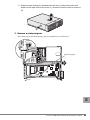
1
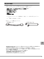
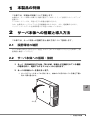
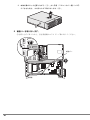
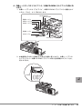
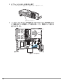
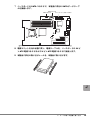
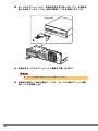
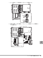
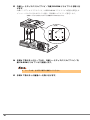
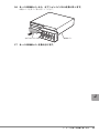
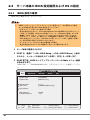
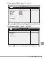
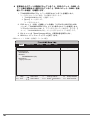
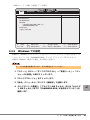
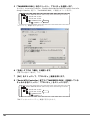
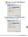
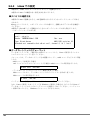
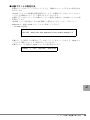
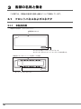
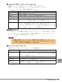
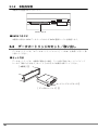
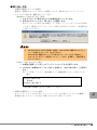
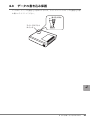
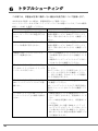
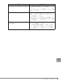
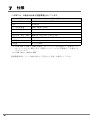
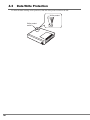
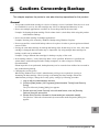
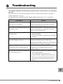
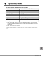
B7FY-2111-02 内蔵データカートリッジドライブユニット 取扱説明書 Internal Data Cartridge Drive Unit User’s Guide (PG-RD101) J E はじめに このたびは、弊社の内蔵データカートリッジドライブユニット(PG-RD101)をお買い上 げいただき、誠にありがとうございます。 本書は、内蔵データカートリッジドライブユニット(以降、本製品)の取り扱いの基本的 なことがらについて説明しています。ご使用になる前に、本書をよくお読みになり、正し い取り扱いをされますようお願いいたします。 2007 年 10 月 安全にお使いいただくために 本書には、本製品を安全に正しくお使いいただくための重要な情報が記載されています。 本製品をお使いになる前に、本書を熟読してください。特に、本書の「安全上のご注意」をよくお読みにな り、理解されたうえで本製品をお使いください。 また本書は、本製品の使用中にいつでもご覧になれるよう大切に保管してください。 本製品のハイセイフティ用途での使用について 本製品は、一般事務用、パーソナル用、家庭用、通常の産業用等の一般的用途を想定して設計・製造されて いるものであり、原子力施設における核反応制御、航空機自動飛行制御、航空交通管制、大量輸送システム における運行制御、生命維持のための医療器具、兵器システムにおけるミサイル発射制御など、極めて高度 な安全性が要求され、仮に当該安全性が確保されない場合、直接生命・身体に対する重大な危険性を伴う用 途(以下「ハイセイフティ用途」という)に使用されるよう設計・製造されたものではございません。お客 様は、当該ハイセイフティ用途に要する安全性を確保する措置を施すことなく、本製品を使用しないでくだ さい。ハイセイフティ用途に使用される場合は、弊社の担当営業までご相談ください。 当社のドキュメントには「外国為替および外国貿易管理法」に基づく特定技術が含まれていることがありま す。特定技術が含まれている場合は、当該ドキュメントを輸出または非居住者に提供するとき、同法に基づ く許可が必要となります。 2 本書の表記 ■ 警告表示 本書ではいろいろな絵表示を使っています。これは本製品を安全に正しくお使いいただ き、あなたや他の人々に加えられるおそれのある危害や損害を未然に防止するための目印 となるものです。その表示と意味は次のようになっています。内容をよくご理解の上、お 読みください。 警告 この表示を無視して、誤った取り扱いをすると、人が死亡する可能性 または重傷を負う可能性があることを示しています。 注意 この表示を無視して、誤った取り扱いをすると、人が損害を負う可能 性があること、および物的損害のみが発生する可能性があることを示 しています。 また、危害や損害の内容がどのようなものかを示すために、上記の絵表示と同時に次の記 号を使用しています。 △で示した記号は、警告・注意を促す内容であることを告げるもので す。記号の中やその脇には、具体的な警告内容が示されています。 で示した記号は、してはいけない行為(禁止行為)であることを告 げるものです。記号の中やその脇には、具体的な禁止内容が示されて います。 ●で示した記号は、必ず従っていただく内容であることを告げるもの です。記号の中やその脇には、具体的な指示内容が示されています。 ■ 本文中の記号 本文中に記載されている記号には、次のような意味があります。 記号 意味 お使いになる際の注意点や、してはいけないことを記述しています。 必ずお読みください。 ハードウェアやソフトウェアを正しく動作させるために必要なことが 書いてあります。必ずお読みください。 → 参照ページや参照マニュアルを示しています。 J 3 ■ 製品の呼び方 本文中の製品名称を次のように略して表記します。 製品名称 内蔵データカートリッジドライブユニット (PG-RD101) ® 本文中の表記 本製品 ® Microsoft Windows Server 2003, Standard Edition Microsoft® Windows Server® 2003, Enterprise Edition Microsoft® Windows Server® 2003 R2, Standard Edition Windows Server 2003 Microsoft® Windows Server® 2003 R2, Enterprise Edition Microsoft® Windows Server® 2003, Standard x64 Edition Microsoft® Windows Server® 2003, Enterprise x64 Edition Microsoft® Windows Server® 2003 R2, Standard x64 Edition Windows Windows Server 2003 x64 Microsoft® Windows Server® 2003 R2, Enterprise x64 Edition Microsoft® Windows® 2000 Server Red Hat® Enterprise Linux ES (v.3 for x86) Red Hat® Enterprise Linux® AS (v.3 for x86) Red Hat® Enterprise Linux® ES (v.4 for x86) Red Hat® Enterprise Linux® AS (v.4 for x86) Red Hat® Enterprise Linux® ES (v.4 for EM64T) Red 4 Hat® Windows 2000 Server ® Enterprise Linux® AS (v.4 for EM64T) Linux v.3 Linux v.4 Linux v.4 for EM64T Red Hat® Enterprise Linux® 5 (for x86) Linux v.5 Red Hat® Enterprise Linux® 5 (for Intel64) Linux v.5 for Intel64 Linux SUSE™ Linux® Enterprise Server 9 for x86 SUSE Linux BrightStor ARCserve Backup r11.5 for Windows BrightStor ARCserve Backup Windows 用バックアップユーティリティ Windows Backup 安全上のご注意 本製品を安全にお使いいただくために、以降の記述内容を必ずお守りください。 ■ 本製品の取り扱いについて 警告 ・ 梱包に使用しているビニール袋はお子様が口に入れたり、かぶって遊んだりし ないよう、ご注意ください。窒息の原因となります。 ・ 異物(水・金属片・液体など)が本製品の内部に入った場合は、ただちにサー バ本体の電源スイッチを切り、電源プラグをコンセントから取り外してくださ い。 その後、修理相談窓口にご連絡ください。 そのまま使用すると、感電・火災の原因となります。特にお子様のいるご家庭 ではご注意ください。 ・ 開口部(通風孔など)から内部に金属類や燃えやすいものなどの異物を差し込 んだり、落としたりしないでください。感電・火災の原因となります。 ・ 本製品をお客様自身で改造しないでください。感電・火災の原因となります。 注意 ・ 本製品を分解したり、解体したりしないでください。 ・ 本製品は次の環境で動作させたり、保管したりしないでください。 - 極端な低温環境 - 極端な高温/多湿環境 - 温湿度変化の激しい環境 - 磁気の影響を受けやすい場所 - 衝撃や振動の加わる場所 - ゴミやほこり(煙草の煙、土埃、排気ガスなど)の多い環境 - 直射日光のあたる場所 - 発熱器具のそば ・ 寒い場所から暖かい場所に移動したり、室温を急に上げたりした直後は、内部 が結露する場合がありますので、使用しないでください。 結露したままお使いになると、本製品やデータカートリッジを損傷することが あります。大きな温度変化があったときは、1 時間以上待ってから電源を入れ てください。 J 5 注意 ・ 使用しない場合は、本製品からデータカートリッジを取り出してください。 ・ データカートリッジを入れたまま本製品を持ち運ばないでください。 ・ データカートリッジのセット時、無理に押し込まないでください。 ・ 内部に液体や金属など異物が入った状態で使用しないでください。 何か異物が入った場合は、修理相談窓口にご相談ください。 ・ 本製品前面の汚れは、柔らかい布でからぶきしてください。からぶきで落ちな い汚れは、中性洗剤をしみ込ませて固くしぼった布で拭いてください。汚れが 落ちたら、水に浸して固くしぼった布で、中性洗剤を拭き取ってください。拭 き取りのときは、本製品およびサーバ本体に水が入らないようにご注意くださ い。 中性洗剤以外の洗剤や溶剤などは使用しないでください。 ■ リサイクルについて 本製品を廃棄する場合、担当営業員に相談してください。本製品は産業廃棄物として処理 する必要があります。 6 梱包物の確認 お使いになる前に、次のものが梱包されていることをお確かめください。 万一足りないものがございましたら、担当営業員にご連絡ください。 ( *1) ・ 内蔵データカートリッジドライブユニット(本製品) ( *1) ・ 取り付けレール(2 本) ・ SATA 電源ケーブル( *1) ・ SATA データケーブル( *1) ・ 保証書( *2) ・ 取扱説明書(本書) *1:カスタムメイドサービス(PGBRD101)の場合、サーバ本体に組み込まれていま す。 *2:一般製品(PG-RD101)のみ添付。 添付のケーブルの概観を次に示します。 SATA㔚Ḯ䉬䊷䊑䊦 SATA䊂䊷䉺䉬䊷䊑䊦 J Microsoft、Windows、Windows Server は、米国 Microsoft Corporation の米国およびその他の国におけ る登録商標または商標です。 Linux は、Linus Torvalds 氏の米国およびその他の国における登録商標あるいは商標です。 Red Hat および Red Hat をベースとしたすべての商標とロゴは、米国およびその他の国における Red Hat, Inc. の商標または登録商標です。 SUSE は、米国およびその他の国における Novell Inc. の商標です。 その他の会社名、製品名は、各社の登録商標または商標です。 その他の各製品は、各社の著作物です。 All Rights Reserved, Copyright© FUJITSU LIMITED 2007 7 目次 1 本製品の特徴 . . . . . . . . . . . . . . . . . . . . . . . . . . . . . . . . . . . . . . . 9 2 サーバ本体への搭載と導入方法 . . . . . . . . . . . . . . . . . . . . . . . . . 9 2.1 設置環境の確認 . . . . . . . . . . . . . . . . . . . . . . . . . . . . . . . . . . . . . . . . . . . 9 2.2 サーバ本体への搭載・接続 . . . . . . . . . . . . . . . . . . . . . . . . . . . . . . . . . . 9 2.3 サーバ本体の BIOS 設定確認および OS の設定 . . . . . . . . . . . . . . . . . 3 各部の名称と働き . . . . . . . . . . . . . . . . . . . . . . . . . . . . . . . . . . . 3.1 フロントパネルおよびコネクタ . . . . . . . . . . . . . . . . . . . . . . . . . . . . . . 3.2 データカートリッジのセット/取り出し . . . . . . . . . . . . . . . . . . . . . . . 4 データカートリッジについて . . . . . . . . . . . . . . . . . . . . . . . . . . . 4.1 使用できるデータカートリッジ . . . . . . . . . . . . . . . . . . . . . . . . . . . . . . 8 18 26 26 28 30 30 4.2 データカートリッジの取り扱い . . . . . . . . . . . . . . . . . . . . . . . . . . . . . . 30 4.3 データの書き込み保護 . . . . . . . . . . . . . . . . . . . . . . . . . . . . . . . . . . . . . 31 5 バックアップ運用上の注意 . . . . . . . . . . . . . . . . . . . . . . . . . . . . 32 6 トラブルシューティング . . . . . . . . . . . . . . . . . . . . . . . . . . . . . . 34 7 仕様 . . . . . . . . . . . . . . . . . . . . . . . . . . . . . . . . . . . . . . . . . . . . . . 36 1 本製品の特徴 この章では、本製品の特徴について説明します。 本製品は、サーバ本体に内蔵する交換可能なデータカートリッジを使用したバックアップ 装置です。 データカートリッジは、用途に応じた容量を選択できます。 なお、本製品はハードウェアによる圧縮機能はありません。また、連続動作させたり、 バックアップしたデータを長期保管する用途には向いていません。 2 サーバ本体への搭載と導入方法 この章では、サーバ本体への搭載方法と導入方法について説明します。 2.1 設置環境の確認 サーバ本体に添付の『安全上のご注意』および『はじめにお読みください』を参照し、設 置環境を確認してください。 2.2 サーバ本体への搭載・接続 1 サーバ(PRIMERGY TX120 / TX120W)本体および接続されている機器 の電源を切り、電源プラグをコンセントから抜きます。 2 サーバの本体カバーを取り外します。 1. サーバをフットスタンドから取り外し、本体のゴム足が付いている面を下側に 向けて横に置きます。 J 䉯䊛⿷ 1 本製品の特徴 9 2. 本体上面のロックを押しながら(①) 、少し手前(フロントカバー側)にスラ イドさせたあと、上に持ち上げて取り外します(②) 。 3 補強バーを取り外します。 ①を持ち上げて外したあと、②を背面側にスライドして取り外してください。 ᒝࡃ ೨㕙 10 ⢛㕙 4 内蔵ハードディスクドライブベイ/内蔵 CD-ROM ドライブベイを取り外 します。 1. 内蔵ハードディスクドライブベイ、内蔵 CD-ROM ドライブベイに接続されて いるケーブルを、すべて取り外します。 SAS䉮䊈䉪䉺1 SAS䉮䊈䉪䉺2 㔚Ḯ䉬䊷䊑䊦 SAS䉬䊷䊑䊦2 SAS䉬䊷䊑䊦1 㔚Ḯ䉬䊷䊑䊦 IDE䉬䊷䊑䊦 㪪㪘㪪㩷㪣㪜㪛䉬䊷䊑䊦 2. 本体側面の PUSH と記載された部分を外側に押しながら、内蔵ハードディス クドライブベイ/内蔵 CD-ROM ドライブベイ部分を前面側にスライドさせ、 持ち上げます。 PUSH J 2 サーバ本体への搭載と導入方法 11 5 オプションベイカバーを取り外します。 カバーの 2 か所の穴に指を入れて手前に引いて取り外します。 䉥䊒䉲䊢䊮䊔䉟䉦䊋䊷 6 ベースボードの 24 ピン ATX 電源コネクタおよび 4 ピン ATX 電源コネク タに接続されている電源ケーブルを取り外し(①)、電源ユニットを引き 起こします(②)。 㔚Ḯ䊡䊆䉾䊃䉕ᒁ䈐䈖䈜 㽳 ೨㕙 ⢛㕙 㽲㔚Ḯ䉬䊷䊑䊦ข䉍ᄖ䈜 12 7 ベースボードの SATA コネクタに、本製品に添付の SATA データケーブ ルを接続します。 SATAࠦࡀࠢ࠲ USBࠦࡀࠢ࠲ ࡈࡠ࠶ࡇ࠺ࠖࠬࠢࠦࡀࠢ࠲ ೨㕙 ⢛㕙 8 電源ユニットを元の状態に戻し、電源ケーブルを、ベースボードの 24 ピ ン ATX 電源コネクタおよび 4 ピン ATX 電源コネクタに接続します。 9 本製品に添付の取り付けレールを、本製品に取り付けます。 J 2 サーバ本体への搭載と導入方法 13 10 サーバのオプションベイに、本製品を途中まで差し込み(①)、本製品背 面に SATA データケーブルと SATA 電源ケーブルを接続します(②)。 㨇ᧄຠ⢛㕙㨉 11 本製品をサーバのオプションベイに最後まで押し込みます。 ケーブルを挟み込まないように注意してください。 12 本製品に接続した SATA 電源ケーブルに、サーバの内蔵オプション用電 源ケーブルを接続します。 14 1. サーバ内部のケーブル類を留めているクリップを解除します。 䉪䊥䉾䊒 2. 本製品に接続した SATA 電源ケーブルと、サーバの内蔵オプション用電源ケー ブルを接続します。 㪪㪘㪫㪘䊂䊷䉺䉬䊷䊑䊦 㪪㪘㪫㪘䉮䊈䉪䉺 ᧄຠ 㪪㪘㪫㪘㔚Ḯ䉬䊷䊑䊦 㔚Ḯ䊡䊆䉾䊃 J ౝ⬿䉥䊒䉲䊢䊮↪㔚Ḯ䉬䊷䊑䊦 2 サーバ本体への搭載と導入方法 15 13 内蔵ハードディスクドライブベイ/内蔵 CD-ROM ドライブベイを取り付 けます。 内蔵ハードディスクドライブベイ/内蔵 CD-ROM ドライブベイの底面の突起をオ プションベイの穴に合わせるように置き、背面側にスライドして固定します。 o ౝ⬿䊊䊷䊄䊂䉞䉴䉪䊄䊤䉟䊑䊔䉟㪆ౝ⬿㪚㪛㪄㪩㪦㪤䊄䊤䉟䊑䊔䉟 䌛ᐩ㕙䌝 ⓭ 14 手順 4 で取り外したケーブルを、内蔵ハードディスクドライブベイ/内 蔵 CD-ROM ドライブベイに接続します。 ケーブルは、必ず同じ場所に接続してください。 15 手順 3 で取り外した補強バーを取り付けます。 16 16 サーバの本体カバーから、オプションベイパネルを取り外します。 内側のツメを外して取り外してください。 䉥䊒䉲䊢䊮䊔䉟䊌䊈䊦 ᧄ䉦䊋䊷 17 サーバの本体カバーを取り付けます。 J 2 サーバ本体への搭載と導入方法 17 2.3 サーバ本体の BIOS 設定確認および OS の設定 2.3.1 BIOS 設定の確認 BIOS 設定の確認方法を、次に示します。 内蔵データカートリッジドライブユニットをご使用になり、次の運用をする場合 は、必ず後述の手順に従い BIOS 設定を行ってください。 ・FDD ユニット(USB)をご使用になる場合 後述の設定を行わないと、Server Management Tool の使用時などの FDD ユニット (USB)からの起動、Windows の手動インストール、Windows の自動システム回 復機能(ASR)などで、フロッピーディスクへのアクセスができなくなります。 FDD ユニット(USB)を一度取り外して再度接続した場合は、そのつど後述の BIOS 設定を行ってください(Windows で FDD ユニット(USB)を使用する際に は、BIOS 設定に関わらずお使いいただけます) 。 ・データカートリッジを入れたままの運用をする場合 後述の設定を行わないと OS の起動ができなくなる場合があります。 1 サーバ本体の電源を入れます。 2 POST 中、画面に「<F2> BIOS Setup / <F12> BOOT Menu」と表示 されたら、メッセージが表示されている間に、【F2】キーを押します。 3 POST 終了後、BIOS セットアップユーティリティの Main メニュー画面 が表示されます。 「Native IDE」に「TANDBERGRDX-(TS)」と表示されていることを確認してくださ い。 Main Advanced Security Server System Time: System Date: [HH:MM:SS] [MM:DD:YYYY] Standard IDE: Native IDE: [******] [TANDBERGRDX-(TS)] Exit Item Specific Help Boot Options Base Memory: Extended Memory: F1 Help Esc Exit 18 640KB ***M Select Item Select Menu Change Values -/+ Enter Select Sub-Menu F9 Setup Defaults F10 Save and Exit 4 「Boot Options」を選択し、【Enter】キーを押します。 Boot Options サブメニューが表示されます。 Main Advanced Security Server Exit Boot Options Item Specific Help [Halt On All Errors] [Enabled] [Enabled] [Disabled] [Disabled] [Enabled] [Auto] [Enabled] POST Errors: Keyboard Check: SM Error Halt: Fast Boot: Quiet Boot: Boot Menu: NumLock: MultiBoot for HDs: Boot Sequence F1 Help Esc Exit Select Item Select Menu -/+ Change Values Enter Select Sub-Menu F9 Setup Defaults F10 Save and Exit 5 Boot Sequence を選択し、【Enter】キーを押します。 Main Advanced Security Server Exit Boot Sequence Item Specific Help Boot Sequence: CD-ROM Drive +Diskette +Hard Drive Legacy LAN card J F1 Help Esc Exit Select Item Select Menu -/+ Change Values Enter Select Sub-Menu F9 Setup Defaults F10 Save and Exit 2 サーバ本体への搭載と導入方法 19 6 本製品からのブートが無効になっていること、FDD ユニット(USB)の ブート順が本製品より優先されていること(FDD ユニット(USB)を接 続している場合)を確認します。 1. 「TANDBERGRDX-(TS)」に「!」が表示されていることを確認します。 「!」が表示されていない場合、次の操作で表示します。 1. 「TANDBERGRDX-(TS)」を選択します。 2. 【Space】キーを押します。 「!」が表示されます。 2. FDD ユニット(USB)を接続している場合、 「Y-E DATA USB-FDD-(USB 1.1)」が、 「TANDBERGRDX-(TS)」より上に表示されてことを確認します。 「Y-E DATA USB-FDD-(USB 1.1)」が下に表示されている場合は、 【+】 【-】 キーで、 「TANDBERGRDX-(TS)」より上に表示されるように設定します。 3. Exit メニューの「Save Changes & Exit」で変更内容を保存します。 4. BIOS セットアップユーティリティを終了します。 ・ FDD ユニット(USB)を接続していない場合 Main Advanced Security Server Exit Boot Sequence Item Specific Help Boot Sequence: CD-ROM Drive: +Diskette ! ޓޓTANDBERGRDX-(TS) +Hard Drive Legacy LAN card F1 Help Esc Exit 20 Select Item Select Menu -/+ Change Values Enter Select Sub-Menu F9 Setup Defaults F10 Save and Exit ・ FDD ユニット(USB)を接続している場合 Main Advanced Security Server Exit Boot Sequence Item Specific Help Boot Sequence: CD-ROM Drive: +Diskette ޓޓY-E DATA USB-FDD-(USB 1.1) ! TANDBERGRDX-(TS) +Hard Drive Legacy LAN card F1 Help Esc Exit Select Item Select Menu -/+ Change Values Enter Select Sub-Menu F9 Setup Defaults F10 Save and Exit Windows での設定 2.3.2 本製品は、Windows のエクスプローラではリムーバブルディスクとして表示されます(デ バイスマネージャでは「TANDBERG RDX」ディスクドライブとして表示されます) 。 本製品を Windows で使用する場合、次の設定が必要です。 十分な性能を発揮するために、必ず本設定を行ってください。 1 「スタート」ボタン→「すべてのプログラム」→「管理ツール」→「コン ピュータの管理」の順にクリックします。 2 「デバイスマネージャ」をクリックします。 3 「表示」メニューから「デバイス(接続別)」を選択します。 4 デバイスツリーを展開し、「プライマリ IDE チャネル」または「セカンダ リ IDE チャネル」配下に「TANDBERG RDX」が表示されていることを 確認します。 J 2 サーバ本体への搭載と導入方法 21 5 「TANDBERG RDX」を右クリックし、プロパティを選択します。 次の図は、Serial ATA Controller 「Intel(R) 82801GB/GR/GH(ICH7 Family) Serial ATA Storage Controller」配下に「TANDBERG RDX」が接続されている例です。 䎬䏑䏗䏈䏏䎋䎵䎌䎃 䎛䎕䎛䎓䎔䎪䎥䎒䎪䎵䎒䎪䎫䎃 䎋䎬䎦䎫䎚䎃 䎩䏄䏐䏌䏏䏜䎌䎃 䎶䏈䏕䏌䏄䏏䎃 䎤䎷䎤䎃 䎶䏗䏒䏕䏄䏊䏈䎃 䎦䏒䏑䏗䏕䏒䏏䏏䏈䏕䎃 䎐 䮂䭲䮺䮇䮱䎃 䎬䎧䎨䎃 䮈䮪䮔䮲䎃 䎃 䮞䮰䭫䮥䮱䎃 䎬䎧䎨䎃 䮈䮪䮔䮲䎃 䎷䎤䎱䎧䎥䎨䎵䎪䎃䎵䎧䎻䎃 ᳢↪䮣䮱䮬䯃䮧䎃 「プロパティ」画面が表示されます。 6 「全般」タブ内の「場所」を確認します。 手順 5 内の図は「場所 1」です。 7 [OK]をクリックして、「プロパティ」画面を閉じます。 8 「Serial ATA Controller」配下の「TANDBERG RDX」を接続している チャネルを右クリックし、「プロパティ」をクリックします。 䎬䏑䏗䏈䏏䎋䎵䎌䎃 䎛䎕䎛䎓䎔䎪䎥䎒䎪䎵䎒䎪䎫䎃 䎋䎬䎦䎫䎚䎃 䎩䏄䏐䏌䏏䏜䎌䎃 䎶䏈䏕䏌䏄䏏䎃 䎤䎷䎤䎃 䎶䏗䏒䏕䏄䏊䏈䎃 䎦䏒䏑䏗䏕䏒䏏䏏䏈䏕䎃 䎐 䮂䭲䮺䮇䮱䎃 䎬䎧䎨䎃 䮈䮪䮔䮲䎃 䎃 䮞䮰䭫䮥䮱䎃 䎬䎧䎨䎃 䮈䮪䮔䮲䎃 䎷䎤䎱䎧䎥䎨䎵䎪䎃䎵䎧䎻䎃 ᳢↪䮣䮱䮬䯃䮧䎃 「IDE チャネルのプロパティ」画面が表示されます。 22 9 「詳細設定」タブの「デバイス 1」(手順 6 で確認した場所「番号 1」にあ たる)の「転送モード」を「PIO のみ」から「DMA(利用可能な場合)」 に変更し、[OK]をクリックします。 設定変更後に再起動する必要はありません。 10 再度、「Serial ATA Controller」配下の「TANDBERG RDX」が接続して いる IDE チャネルを右クリックし、「プロパティ」を選択し、IDE チャネ ルのプロパティの「詳細」タブをクリックします。 次のように、 「転送モード」が「DMA(利用可能な場合) 」 、 「現在の転送モード」 が「Ultra DMA モード 4」になっていれば、設定完了です。 J 2 サーバ本体への搭載と導入方法 23 2.3.3 Linux での設定 本製品は、Linux ではリムーバブルディスクとして認識されます。 本製品の Linux での確認方法・設定方法を次に示します。 ■ デバイスの確認方法 本製品が Linux で認識されると、OS 起動時に次に示すようなロギングメッセージが出力 されます。 dmesg コマンドにより、ロギングメッセージの内容から、認識されたデバイス名を確認し てください。 本製品が "/dev/sdb" として認識されたときのロギングメッセージの出力例を示します。 ・ ロギングメッセージの出力例 ...... scsi2 : ata_piix Vendor: TANDBERG Model: RDX Rev: **** Type: Direct-Access ANSI SCSI revision: 03 Attached scsi removable disk sdb at scsi1, channel 0, id 1, lun 0 ...... ■ データカートリッジのフォーマット データカートリッジは、ご購入時の NTFS フォーマットから、Linux で使用するファイル システムにフォーマットし直してください。 フォーマットは、データカートリッジを本装置にセットし、mkfs コマンドなどにより実施 します。 ・ mkfs コマンドを使用する場合 ext3 ファイルシステムにフォーマットする場合の mkfs コマンドの実行例を示します。 # mkfs.ext3 /dev/sdb1 ・ データカートリッジのパーティション構成を変更する場合 fdisk コマンドにより、データカートリッジのパーティションを作成し直します。 fdisk コマンドの実行例を示します。 # fdisk /dev/sdb パーティションの設定は、fdisk コマンドのメニューに従って行ってください。 なお、Linux で使用したカートリッジを Windows で使用する場合は、あらかじめ Linux で データカートリッジのすべてのパーティションを削除しておいてください。パーティショ ン情報が残っていると、Windows でフォーマットが行えません。 24 ■ 自動マウントの設定方法 本製品にデータカートリッジをセットしたとき、自動的にマウントするための設定方法を 次に示します。 /etc/fstab ファイルに本装置の情報を設定することで、本製品にデータカートリッジをセッ トしたとき自動的にマウントして使用できるようになります。 本製品でデータカートリッジを自動マウントして使用する場合の、/etc/fstab ファイルの設 定例を示します。 /etc/fstab ファイル設定後の、次の OS 起動から有効になります(マウントポイント:/ media/rdx は、事前に mkdir コマンドにより作成してください) 。 ・ /etc/fstab の設定例 ...... /dev/sdb1 /media/rdx auto pamconsole,exec,noauto,managed 0 0 ...... 自動マウントを使用しない場合は、データカートリッジをセットしたあとで、mount コマ ンドにより手動でマウントして使用することもできます。 手動でマウントする場合の mount コマンドの実行例を示します。 # mount -t ext3 /dev/sdb1 /media/rdx J 2 サーバ本体への搭載と導入方法 25 3 各部の名称と働き この章では、本製品の各部の名称と働きについて説明しています。 3.1 フロントパネルおよびコネクタ 3.1.1 本製品前面 本製品の前面は、次のとおりです。 ✕ᕆขࠅߒⓣ ࠗࠫࠚࠢ࠻ࡏ࠲ࡦ㧛࡙࠾࠶࠻ࠗࡦࠫࠤ࠲ ̪ࠗࠫࠚࠢ࠻ࡏ࠲ࡦߣ࡙࠾࠶࠻ࠗࡦࠫࠤ࠲ߪ↪ߢߔޕ 㨇ᧄຠߦ࠺࠲ࠞ࠻࠶ࠫࠍᝌߒߚ⁁ᘒ㨉 ࠞ࠻࠶ࠫࠗࡦࠫࠤ࠲ 26 ■ イジェクトボタン/ユニットインジケータ 本製品に入っているデータカートリッジを取り出すときに押します。 通常は、このボタンを使用せずソフトウェア上から取り出してください。 ユニットインジケータは、本製品の状態を表示します。 表示 状態 消灯 本製品に電源が入っていません。 緑色点灯 本製品に電源が入っており、使用可能な状態です。 緑色点滅 データカートリッジを取り出し中です。 橙色点灯 本製品がエラーを検出しました(データカートリッジの取り出しに失 敗したか、または本製品が故障している可能性があります) 。 橙色点滅 データカートリッジへアクセスがある状態でイジェクトボタンが押さ れました。数秒間橙色に点滅したあと、緑色点灯に戻ります。ソフト ウェアによってデータカートリッジの取り出しが禁止されていない場 合は、その後データカートリッジが排出されます。 ■ 緊急取り出し穴 データカートリッジを強制的に排出するための穴です。クリップの先など細いもので押す と、データカートリッジが排出されます。本製品に電源が入っていないときに、データ カートリッジを取り出す場合に使用してください。 本製品に電源が入っているときには、緊急取り出し穴を使用してデータカートリッ ジを排出しないでください。OS /バックアップソフトウェアのエラーや、データ カートリッジ内のデータが破損することがあります。 ■ カートリッジインジケータ 本製品にセットされているデータカートリッジの状態を表示します。 表示 状態 消灯 データカートリッジに電源がきていません。データカートリッジ が正しくセットされていない、またはデータカートリッジが故障 している可能性があります。 緑色点灯 データカートリッジが使用可能な状態です。 緑色点滅 データカートリッジが動作中です。 橙色点灯 または橙色点滅 本製品がデータカートリッジのエラーを検出しました(データ カートリッジが故障している可能性があります) 。 J 3 各部の名称と働き 27 3.1.2 本製品背面 本製品の背面図は次のとおりです。 SATAࠦࡀࠢ࠲ ■ SATA コネクタ 本製品に添付の SATA データケーブルおよび SATA 電源ケーブルを接続します。 3.2 データカートリッジのセット/取り出し データカートリッジは、 「4 データカートリッジについて」 (→ P.30)を参照して正しく取 り扱ってください。 ■ セット方法 データカートリッジは、本製品が横向きの場合、ラベル面が手前でカートリッジインジ ケータが下側になる方向で、ゆっくりと止まるまで本製品に挿入してください。 [本製品] カートリッジインジケータ [データカートリッジ] 28 ■ 取り出し方法 ・ 本製品の電源が入っている場合 通常は、本製品のイジェクトボタンを使用しないで、OS またはバックアップソフト ウェア上から取り出し操作を行ってください。 - Windows から取り出しを行う場合 1. エクスプローラに表示されている本製品を右クリックします。 2. 表示されるメニューから「取り出し」を選択します。 次のメッセージが表示された場合、データカートリッジへのアクセスが行われ ています。使用中のアプリケーションを終了させるなどしたあと、再度取り出 しを行ってください。 Windows Server 2003 を使用する場合、Administrator 権限がないとカート リッジの排出やフォーマットを行えません。 Administrator 権限がないユーザで排出やフォーマットを行う場合は、 「・ セキュリティポリシーの変更について」(→ P.32)を照参し、設定変更を 行ってください。 - Linux から取り出しを行う場合 1. 本製品を使用しているバックアップソフトウェアなどを終了します。 2. unmount し本製品のイジェクトボタンを押すか、 「eject /dev/sdb1 *」を実行し ます。 例:データカートリッジ(/dev/sdb1 *)が /media/rdx にマウントされている 場合 # eject /media/rdx または # eject /dev/sdb1 * * /dev/sdb1 は環境に合わせて変更してください。 ・ 本製品の電源が入っていない場合 ユニットインジケータおよびカートリッジインジケータが消灯していることを確認し、 緊急取り出し穴にクリップの先など細いものを入れて押してください。 J 3 各部の名称と働き 29 4 データカートリッジについて この章では、本製品で使用できるデータカートリッジについて説明しています。 4.1 使用できるデータカートリッジ 本製品には、次の富士通純正品を使用してください。 商品番号 記憶容量(*) 備考 データカートリッジディスク RD 40GB 0162110 40GB NTFS フォーマット データカートリッジディスク RD 80GB 0162120 80GB NTFS フォーマット データカートリッジディスク RD 120GB 0162130 120GB NTFS フォーマット 品名 *:1GB=1000 × 1000 × 1000byte 換算。未フォーマット時の容量です。 実際にバックアップできる容量は、この値よりも少なくなります。 問い合わせ先:富士通コワーコ株式会社 お客様総合センター (フリーダイヤル) 電話 : 0120-505-279 受付時間:月曜日~金曜日 9:00 ~ 17:30(土、日、祝日・年末年始を除く) 4.2 データカートリッジは消耗品です。購入後 5 年を目安に交換してください。 データカートリッジの取り扱い 本製品で使用するデータカートリッジの取り扱い方法および注意事項について説明しま す。データカートリッジを取り扱うときは、次の事項をお守りください。 ・ 衝撃を与えないでください。 ・ 強磁界の発生する機器に近づけないでください。 ・ ほこりが多い場所には置かないでください。 ・ データカートリッジを分解しないでください。 ・ データカートリッジは消磁しないでください。 ・ データカートリッジのセット時、無理に押し込まないでください。 ・ 結露を避けるため、急激な温湿度変化(15 ℃/時間、20% /時間以上の変化)を伴う 環境下でのご使用/保管は避けてください。 ・ 使用環境が急激に変わった場合、新しい環境下で 24 時間以上放置したあとにご使用く ださい。 ・ ラベル面(データカートリッジ前面)以外の場所にラベルなどを貼らないでください。 ・ データカートリッジは長期保管する用途には向いていません。 ・ データカートリッジを保管する場合は、データカートリッジのプラスチック容器に入 れ、次に示す保管環境の温度、湿度条件を守って保管してください。 項目 温度 30 保管条件 10 ~ 30 ℃ 湿度 20 ~ 60%(ただし、結露しないこと) 最大湿球温度 24 ℃以下 4.3 データの書き込み保護 データカートリッジを書き込み禁止にするには、ライトプロテクトスイッチを書き込み禁 止側にスライドしてください。 ᦠ߈ㄟߺᱛ ࠗ࠻ࡊࡠ࠹ࠢ࠻ ࠬࠗ࠶࠴ J 4 データカートリッジについて 31 5 バックアップ運用上の注意 この章では、本製品のバックアップ運用上の注意事項について説明しています。 ■ 全般 ・ 本製品およびデータカートリッジは、サーバのハードディスクのバックアップを目的と した装置です。サーバのハードディスクとして使用すると、データカートリッジの故障 /破損などによりデータが失われるおそれがあります。 ・ 本製品に、複数のアプリケーションやユーティリティを使用して、同時にアクセスしな いでください。 例:本装置を Windows Backup で使用しているときにデータカートリッジの「ディスク のボリュームチェック」 (チェックディスク)をするなど。 ・ データカートリッジを複数のアプリケーションで使用しないでください。 例:Windows Backup を使用してバックアップしたときに作成されるファイルを Windows のエクスプローラから削除するなど。 ・ ファイルの誤消去を防ぐために、バックアップソフトウェアで作成されたファイルは、 エクスプローラなどで操作しないでください。 ・ 同一データカートリッジ 1 巻によるバックアップ運用では、バックアップに失敗した場 合、全データが失われる危険があります。また、バックアップしたデータカートリッジ が破損した場合にデータが復元できなくなります。複数のデータカートリッジによる バックアップ運用を行うことにより、トラブル発生時の被害を最小限にできます。 例)曜日ごとのデータカートリッジを準備しバックアップ運用する。 ・ バックアップソフトウェアには、バックアップ終了後に「データの検査」の実行を指定 できるものがあります。この指定を行うと、バックアップ終了後にデータカートリッジ に書き込んだデータを読み出して、書き込み内容の検査が行われますので、信頼性を高 めることができます(推奨) 。 データの検査を行っていないと、バックアップ動作中に本製品に不具合が発生した場合 などにデータをリストアできないおそれがあります。 ・ セキュリティポリシーの変更について Windows Server 2003 を使用する場合、Administrator 権限がないとカートリッジの排出や フォーマットを行えません。Administrator 権限がないユーザで排出やフォーマットを行 う場合は、次の手順でセキュリティポリシーの設定変更を行ってください。 1. 管理者アカウントでログオンします。 2. 「スタート」ボタン →「すべてのプログラム」→「管理ツール」→「ローカル セキュリティポリシー」の順にクリックします。 「ローカルセキュティの設定」画面が表示されます。 3. 画面左側のフレームにある「ローカルポリシー」をダブルクリックし、展開さ れた一覧から「セキュリティオプション」をクリックします。 4. 画面右側のフレームにある一覧の中の「デバイス:リムーバブルメディアを取 り出すのを許可する」をダブルクリックします。 「デバイス:リムーバブルメディアを取り出すのを許可するのプロパティ」画 面が表示されます。 32 5. [ローカル セキュリティの設定]タブのプルダウンメニューから、希望の権限 を選択します。 選択できる権限は 3 種類あり、それぞれの意味は次のとおりです。 内容 意味 Administrators 管理者グループのユーザだけに許可 Administrators と Power Users 管理者グループと Power User グループのユーザだけに 許可 Administrators と Interactive Users すべてのユーザに許可 6. [OK]をクリックし、設定を反映させます。 7. 「ローカルセキュリティポリシー設定」画面を閉じ、サーバを再起動します。 ■ Windows Backup ・ Windows Backup では、動作仕様により、十分なデータ転送速度が得られません(7 ~ 11MB/s 程度) 。また、データカートリッジ 2 巻にまたがるバックアップはできません。 ・ Windows Backup でバックアップを行う場合は、 「このバックアップでメディアのデータ を置き換える」を選択してください。 「メディアにこのバックアップを追加する」を選 択すると、残り容量が不足している場合に既存のバックアップデータが消失するため、 選択しないでください。 ■ BrightStor ARCserve Backup ・ BrightStor ARCserve Backup r11.5 for Windows - Japanese L30 以降が必須となります。 ARCserve 製品インストール後、CA 社が提供するモジュールを適用してください。 なお、モジュールの入手方法や適用方法等の詳細については、次のサイトを参照してく ださい。 「内蔵データカートリッジドライブユニットを使用する際の注意事項」 http://software.fujitsu.com/jp/arcserve/notice/windows/pg-rd101.html ・ 本製品を BrightStor ARCserve Backup で使用する場合、次のように設定してください。 -「デバイス環境設定」オプションで「リムーバブルドライブ」を選択してください。 「ファイルシステムデバイス」を選択すると本製品が正常に動作しません。 -「デバイス環境設定」の「リムーバブル ドライブ環境設定」で、 「ロング消去に NTFS を使用する」をチェックしてください。 本項目をチェックしないとロング消去できません。 ・ Windows Server 2003 x64 環境で BrightStor ARCserve Backup のマージを実行した場合、警 告メッセージが表示されシーケンシャルマージ方式でマージ処理が再試行されることが ありますが、マージ処理は正常に行われます。 J 5 バックアップ運用上の注意 33 6 トラブルシューティング この章では、本製品が正常に動作しない場合の対処方法について説明します。 本対処方法で回復しない場合は、修理相談窓口にご連絡ください。 ユニットインジケータおよびカートリッジインジケータの状態については、 「3.1.1 本製品 前面」 (→ P.26)を参照してください。 現象 対処方法 サーバ本体の電源を入れても本製品の 本製品がサーバ本体と正しく接続されているか ユニットインジケータが緑色点灯にな (SATA 電源ケーブル/ SATA データケーブル らない。 が正しく取り付けられているか)を確認してく ださい。 サーバの BIOS セットアップユーティ 本製品がサーバ本体と正しく接続されているか リティで本製品が表示されない。 (SATA 電源ケーブル/ SATA データケーブル が正しく取り付けられているか)を確認してく ださい。 34 本製品が OS /バックアップソフト ウェアで認識されない。 ・ サーバの BIOS セットアップユーティリティ で本製品が表示されているかを確認してくだ さい。 ・ 本製品がバックアップソフトウェアでサポー トされているかを確認してください。 データカートリッジをセットしても、 データカートリッジのカートリッジイ ンジケータが点灯しない。 データカートリッジを取り出し、再度セットし てください。 別のデータカートリッジを使用しカートリッジ インジケータが点灯するかを確認してくださ い。点灯する場合、元のカートリッジが破損し ている可能性があります。 データカートリッジをセットしても、 OS /バックアップソフトウェアが認 識しない。 カートリッジインジケータが緑色点灯している かを確認してください。 OS /バックアップソフトウェアで使用可能な 形式にフォーマットされているかを確認してく ださい。 データカートリッジが OS /バック アップソフトウェア上の操作で排出で きない。 ・ 本製品を使用している可能性のあるソフト ウェアを終了させたあと、再度排出してくだ さい。 ・ サーバ本体を再起動したあと、再度排出して ください。 ・ OS を起動しない状態(BIOS セットアップ ユーティリティなど)で、データカートリッ ジの取り出しが行えるか確認してください。 取り出しできない場合は本製品が故障してい る可能性があります。 現象 対処方法 データカートリッジをセットできな い。 ・ 本製品内部に異物がないかを確認してくださ い。 ・ データカートリッジが破損していないかを確 認してください。 データ転送が遅い。 Windows をご使用の場合、 「2.3.2 Windows での 設定」 (→ P.21)を参照し正しく設定されてい るかを確認してください。 なお、バックアップするデータの状態や、サー バの負荷状況により性能は変化しますので注意 してください。 データカートリッジをセットすると OS が起動しない。 ・ データカートリッジを取り出し、OS が起動 するかを確認してください。 ・「2.3.1 BIOS 設定の確認」 (→ P.18)を参照 し、BIOS が正しく設定されているか確認し てください。 J 6 トラブルシューティング 35 7 仕様 この章では、本製品の仕様と設置環境を示しています。 項目 機能・仕様 品名 内蔵データカートリッジドライブユニット 型名 PG-RD101 データ記憶容量 40GB / 80GB / 120GB(*1) デ-タ転送速度 最大 25MB/s (*2) インタフェース SATA 外形寸法(単位:mm) 横幅 102 ×高さ 41.3 ×奥行き 160 質量 408g(データカートリッジ含まず) 消費電力 最大 19W 発熱量 最大 16.35kJ/h *1:1GB=1000 × 1000 × 1000byte 換算。未フォーマット時の容量です。容量はデータ カートリッジにより異なります(実際にバックアップできる容量は、この値よりも 少なくなります) 。 *2:1MB=1000 × 1000byte 換算 設置環境条件は、サーバ本体に添付の「安全上のご注意」を参照してください。 36 Before Reading This Manual Thank you for purchasing the Fujitsu Internal Data Cartridge Drive Unit (PG-RD101). This manual explains the basic usage of the Internal Data Cartridge Drive Unit (hereafter referred to as "this product"). Before using this product, read this manual in order to ensure proper use. October, 2007 For Your Safety This manual contains important information, required to operate this product safely. Thoroughly review the information in this manual before using this product. Especially note the points under "Safety", and only operate this product with a complete understanding of the material provided. This manual should be kept in an easy-to-access location for quick reference when using this product. High Safety The Products are designed, developed and manufactured as contemplated or general use, including without limitation, general office use, personal use, household use, and ordinary industrial use, but are not designed, developed and manufactured as contemplated for use accompanying fatal risks or dangers that, unless extremely high safety is secured, could lead directly to death, personal injury, severe physical damage, or other loss (hereinafter "High Safety Required Use"), including without limitation, nuclear reaction control in nuclear facility, aircraft flight control, air traffic control, mass transport control, medical life support system, missile launch control in weapon system. You shall not use this Product without securing the sufficient safety required for the High Safety Required Use. If you wish to use this Product for High Safety Required Use, please consult with our sales representatives in charge before such use. E 37 Remarks Warning Descriptions Various symbols are used throughout this manual. These are provided to emphasize important points for your safety and that of others. The symbols and their meanings are as follows. Make sure to fully understand these before reading this manual. WARNING Ignoring this symbol could be potentially lethal. CAUTION Ignoring this symbol may lead to injury and/or damage this product. The following symbols are used to indicate the type of warning or cautions being described. The triangle mark emphasizes the urgency of the WARNING and CAUTION. Details are described next to the triangle. A barred circle ( ) warns against certain actions (Do Not). Details are described next to the circle. A black circle indicates actions that must be taken. Details are described next to the black circle. Symbols The following are symbols used throughout this manual. Symbols Definition These sections explain prohibited actions and points to note when using this product. Make sure to read these sections. These sections explain information needed to operate the hardware and software properly. Make sure to read these sections. → 38 This mark indicates reference pages or manuals. Abbreviations The following expressions and abbreviations are used to describe the product names used in this manual. Product names Internal Data Cartridge Drive Unit (PG-RD101) Expressions and abbreviations This product Microsoft® Windows Server® 2003, Standard Edition Microsoft® Windows Server® 2003, Enterprise Edition Microsoft® Windows Server® 2003 R2, Standard Edition Windows Server 2003 Microsoft® Windows Server® 2003 R2, Enterprise Edition Microsoft® Windows Server® 2003, Standard x64 Edition Microsoft® Windows Server® 2003, Enterprise x64 Edition Microsoft® Windows Server® 2003 R2, Standard x64 Edition Windows Windows Server 2003 x64 Microsoft® Windows Server® 2003 R2, Enterprise x64 Edition Microsoft® Windows® 2000 Server Red Hat® Enterprise Linux® ES (v.3 for x86) Red Hat® Enterprise Linux® AS (v.3 for x86) Red Hat® Enterprise Linux® ES (v.4 for x86) Red Hat® Enterprise Linux® AS (v.4 for x86) Red Hat® Enterprise Linux® ES (v.4 for EM64T) Red Hat® Enterprise Linux® AS (v.4 for EM64T) Windows 2000 Server Linux v.3 Linux v.4 Linux v.4 for EM64T Red Hat® Enterprise Linux® 5 (for x86) Linux v.5 Red Hat® Enterprise Linux® 5 (for Intel64) Linux v.5 for Intel64 SUSE™ Linux® Enterprise Server 9 for x86 SUSE Linux Backup Utility for Windows Windows Backup Linux E 39 Safety For safe use of this product, it is vital that the following warnings are heeded. Handling this product WARNING • Keep the plastic bags used as packing, out of the reach of children. They could cause suffocation. • If a foreign object (water, pieces of metal, liquid) falls into this product, immediately turn off the power and unplug it from the power source. Contact an office listed in "Appendix A Contact Information" (pg.72). Not doing so may cause electric shock and fire. Extreme care should be taken in households with young children. • Do not insert or drop foreign objects such as metals or inflammable objects into openings in this product (ventilating holes, etc.). Doing so may cause electric shock or fire. • Do not remodel this product. Doing so may cause electric shock or fire. 40 CAUTION • Do not disassemble, or take this product apart. • Do not operate or store this product in the following environments. - Areas of extremely low temperature - Areas of extremely high temperature or humidity - Areas that experience extreme temperature changes - Areas exposed to magnetic fields - Areas exposed to shocks or vibration - Dusty or dirty areas (cigarette smoke, emissions) - Areas in direct sunlight - Areas near radiators or other heat sources • If this product is moved from cold areas to hot areas or if room temperature suddenly rises, internal condensation may form. If this product is used after condensation has formed, it may damage this product or the data cartridge. After a large change in temperature, do not turn on the power for 1 hour. • Eject data cartridges when not using them. • Do not carry this product with the data cartridge left in it. • Do not forcibly insert the data cartridge. • Do not use this product if foreign objects such as metals have fallen into this product. If some foreign objects have fallen into this product, contact an office listed in "Appendix A Contact Information" (pg.72). • Use a soft dry cloth to wipe the front when it is dirty. If a dry cloth is not sufficient, use a cloth and mild detergent. After the dirt has been removed use a damp, clean cloth to clean up the detergent residue. Be careful not to get any water in this product or server. Do not use anything stronger than a mild detergent. Recycle When scrapping this product, contact an office listed in "Appendix A Contact Information" (pg.72). This product must be disposed of as industrial waste. E 41 Checking the Items Supplied Before using the product, check that no supplied or attached items are missing. If any items are missing, contact an office listed in "Appendix A Contact Information" (pg.72). • • • • • Internal Data Cartridge Drive Unit (this product) *1 Installation rail (x2) *1 SATA power cable *1 SATA data cable *1 User's Guide (this document) *1: For custom made service (PGBRD101), items are supplied with the server. The following is an external view of the cables supplied with this product. SATA power cable SATA data cable Microsoft, Windows, and Windows Server are trademarks or registered trademarks of Microsoft Corporation in the United States and other countries. Linux is a trademark or registered trademark of Linus Torvalds in the United States and other countries. Red Hat and all Red Hat-based trademarks and logos are trademarks or registered trademarks of Red Hat, Inc. in the United States and other countries. SUSE is a trademark of Novell Inc. in the United States and other countries. Other product names used are trademarks or registered trademarks of their respective manufacturers. Other products are copyrights of their respective manufacturers. All Rights Reserved, Copyright FUJITSU LIMITED 2007 42 Contents 1 Feature . . . . . . . . . . . . . . . . . . . . . . . . . . . . . . . . . . . . . . . . . . . 2 How to Install and Introduce this Product to a Server . . . . . 44 44 2.1 Checking the Setting Environment . . . . . . . . . . . . . . . . . . . . . . . . . . 2.2 Installing and Connecting this Product to the Server . . . . . . . . . . . . 44 44 2.3 Checking the BIOS and OS Settings of the Server . . . . . . . . . . . . . . 53 3 Component Names and Functions . . . . . . . . . . . . . . . . . . . . . 61 3.1 Front Panel and Connector . . . . . . . . . . . . . . . . . . . . . . . . . . . . . . . . 61 3.2 Inserting/Ejecting the Data Cartridge . . . . . . . . . . . . . . . . . . . . . . . . . 63 4 About the Data Cartridge . . . . . . . . . . . . . . . . . . . . . . . . . . . . 65 4.1 Data Cartridges That can be Used . . . . . . . . . . . . . . . . . . . . . . . . . . 65 4.2 Handling the Data Cartridge . . . . . . . . . . . . . . . . . . . . . . . . . . . . . . . 65 4.3 Data Write Protection . . . . . . . . . . . . . . . . . . . . . . . . . . . . . . . . . . . . . 66 5 Cautions Concerning Backup . . . . . . . . . . . . . . . . . . . . . . . . . 6 Troubleshooting . . . . . . . . . . . . . . . . . . . . . . . . . . . . . . . . . . . . 7 Specifications . . . . . . . . . . . . . . . . . . . . . . . . . . . . . . . . . . . . . Appendix A Contact Information . . . . . . . . . . . . . . . . . . . . . . . 67 69 71 72 E 43 1 Feature This chapter explains the feature of this product. This product is a backup device that uses a replaceable data cartridge and can be installed in a server. The capacity of the data cartridge can be selected to meet various requirements. This product does not provide a hardware compression function. Also, this product is not suited for continuous operation and long-term storage of backed up data. 2 How to Install and Introduce this Product to a Server This chapter explains installation and introduction of this product to a server. 2.1 Checking the Setting Environment Refer to the "Safety Precautions" and "Start Guide" supplied with the server, check the setting environment. 2.2 Installing and Connecting this Product to the Server 1 Turn off the server (PRIMERGY TX120/TX120W) and connected devices, and unplug all power cables from the outlet. 2 Remove the cover of the server. 1. Remove the foot stands and lay the server with the rubber feet down. Rubber foot 44 2. Slide the cover toward you (towards the front cover), while pushing the lock button on the upper side of the server (1), and then lift up the cover to remove it (2). 3 Remove a reinforcing bar. After lifting up (1) and disconnecting, pull (2) towards the rear and remove. Reinforcing bar Front Rear E 2 How to Install and Introduce this Product to a Server 45 4 Remove the internal hard disk drive bay / internal CD-ROM drive bay. 1. Remove all cables connected to the internal hard disk drive bay / internal CDROM drive bay. SAS connector 1 SAS connector 2 Power cable SAS cable 2 SAS cable 1 Power cable IDE cable SAS LED cable 2. Pushing the "PUSH" part on the side of the server, slide the internal hard disk drive bay / internal CD-ROM drive bay to the front side and lift it up. PUSH 46 5 Remove the cover of the optional bay. Insert your fingers into two holes of the cover and pull the cover towards you to remove it. The cover of the optional bay 6 Remove the power cables connected to the baseboard 24 pin ATX power connector and 4 pin ATX power connector (1), and pull the power unit up slightly (2). Pull the power unit up slightly 㽳 Front Rear 㽲Remove the power cables E 2 How to Install and Introduce this Product to a Server 47 7 Connect the SATA cable included with this product to the baseboard SATA connector. SATA connector USB connector Floppy disk connector Front Rear 8 Return the power unit to its original position, and reconnect the power cables to the baseboard 24 pin ATX power connector and 4 pin ATX power connector. 9 Install the rails supplied with this product. 48 10 Partially insert this product into the server option bay (1), and connect the SATA data cable and SATA power cable to the rear of this product (2). [Rear of this product] 11 Insert this product fully into the server bay. Be careful not to pinch or catch any cables. 12 Connect the power cable for the server internal option to the SATA power cable connected to this product. E 2 How to Install and Introduce this Product to a Server 49 1. Open the clips which bound the cables in the server. Clip 2. Connect a SATA cable which connected this product and an optional power cable of the server. SATA data cable SATA connector This product SATA power cable Power supply unit Power cable for internal options 50 13 Install the internal hard disk drive bay/internal CD-ROM drive bay. Put the projections on the bottom face of the internal hard disk drive bay / internal CD-ROM drive bay to the holes of the optional bay, and slide it to be fixed. Internal hard disk drive bay / internal CD-ROM drive bay [The bottom face] Projection 14 Connect the cables which are removed in step 4 to the internal hard disk drive bay / internal CD-ROM drive bay. Make sure to connect cables to the same connector. 15 Attach the reinforcing bar which is removed in step 3. E 2 How to Install and Introduce this Product to a Server 51 16 Remove the optional bay panel from the cover of the server. Take off the tab inside of the panel to remove it. Optional bay panel 17 Attach the cover of the server. 52 Cover of the server 2.3 Checking the BIOS and OS Settings of the Server 2.3.1 Checking the BIOS Settings The following shows how to check the BIOS settings. Complete BIOS settings with the procedure described when using an internal data cartridge drive unit and performing the following operations. • Using an FDD unit (USB) Access to the floppy disk will become impossible when booting from the FDD unit (USB) while using the Server Management Tool, or when using the Windows manual installation and automatic system recovery function (ASR) if the settings have not been performed. Perform BIOS settings each time you remove an FDD unit (USB) and re-connect it. (BIOS Settings do not need to be changed when using an FDD unit (USB) from a Windows OS.) • Operating with a data cartridge inserted The OS may become un-bootable when performing operations with the data cartridge inserted if the following settings are not performed. 1 Turn the server on. 2 During POST, press the [F2] key while the message "<F2> BIOS Setup / <F12> BOOT Menu" is displayed on the screen. 3 The Main menu of BIOS Setup Utility is displayed when POST completes. Check that "TANDBERGRDX-(TS)" is displayed in "Native IDE". Main Advanced Security Server System Time: System Date: [HH:MM:SS] [MM:DD:YYYY] Standard IDE: Native IDE: [******] [TANDBERGRDX-(TS)] Exit Item Specific Help Boot Options Base Memory: Extended Memory: 640KB ***M E F1 Help Esc Exit Select Item Select Menu Change Values -/+ Enter Select Sub-Menu F9 Setup Defaults F10 Save and Exit 2 How to Install and Introduce this Product to a Server 53 4 Select "Boot Options" and press the [Enter] key. The Boot Options sub menu is displayed. Main Advanced Security Server Exit Boot Options Item Specific Help [Halt On All Errors] [Enabled] [Enabled] [Disabled] [Disabled] [Enabled] [Auto] [Enabled] POST Errors: Keyboard Check: SM Error Halt: Fast Boot: Quiet Boot: Boot Menu: NumLock: MultiBoot for HDs: Boot Sequence F1 Help Esc Exit Select Item Select Menu -/+ Change Values Enter Select Sub-Menu F9 Setup Defaults F10 Save and Exit 5 Select Boot Sequence and press the [Enter] key. Main Advanced Security Server Exit Boot Sequence Item Specific Help Boot Sequence: CD-ROM Drive +Diskette +Hard Drive Legacy LAN card F1 Help Esc Exit 54 Select Item Select Menu -/+ Change Values Enter Select Sub-Menu F9 Setup Defaults F10 Save and Exit 6 Check that booting from this product is disabled, and the FDD unit (USB) is prioritized before this product (when an FDD unit (USB) is connected). 1. Check if "!" is displayed in front of "TANDBERGRDX-(TS)". If "!" is not displayed, perform the following operation to display it. 1. Select "TANDBERGRDX-(TS)". 2. Press the [Space] key. "!" is displayed. 2. When an FDD unit (USB) is connected, check that "Y-E DATA USB-FDD-(USB 1.1)" is displayed above "TANDBERGRDX-(TS)". If "Y-E DATA USB-FDD-(USB 1.1)" is displayed below "TANDBERDRDX-(TS)", use the [+] and/or [-] key to move it above "TANDBERGRDX-(TS)". 3. Select [Save changes & Exit] in the [Exit] menu to save the changes. 4. The BIOS Setup Utility will end. • When an FDD unit (USB) is not connected: Main Advanced Security Server Exit Boot Sequence Item Specific Help Boot Sequence: CD-ROM Drive: +Diskette ! TANDBERGRDX-(TS) +Hard Drive Legacy LAN card F1 Help Esc Exit Select Item Select Menu -/+ Change Values Enter Select Sub-Menu F9 Setup Defaults F10 Save and Exit E 2 How to Install and Introduce this Product to a Server 55 • When an FDD unit (USB) is connected: Main Advanced Security Server Exit Boot Sequence Item Specific Help Boot Sequence: CD-ROM Drive: +Diskette Y-E DATA USB-FDD-(USB 1.1) ! TANDBERGRDX-(TS) +Hard Drive Legacy LAN card F1 Help Esc Exit 2.3.2 Select Item Select Menu -/+ Change Values Enter Select Sub-Menu F9 Setup Defaults F10 Save and Exit Settings for Windows This product is displayed as a removable disk in Windows Explorer (As "TANDBERG RDX" in the device manager). The following settings are necessary in order to use this product in Windows. In order to increase data transfer rate, make sure to perform the following settings. 1 Click the "Start" button → "All Programs" → "Administrative Tools" → "Computer Management" in this order. 2 Click "Device Manager". 3 In the "View" menu, click "Devices by connection". 4 Open the device tree and check if "TANDBERG RDX" is displayed under "Primary IDE Channel" or "Secondary IDE Channel". 56 5 Right click "TANDBERG RDX", and select Properties. The next diagram shows an example where the "TANDBERG RDX" is added under the Serial ATA Controller "Intel(R) 82801GB/GR/GH (ICH7 Family) Serial ATA Storage Controller". Intel(R) 82801GB/ GR/ GH (ICH7 Family) Serial ATA Storage Controller - Secondary IDE Channel Primary IDE Channel TANDBERG RDX Generic Volume The "Properties" window appears. 6 Check "Location" in the "General" tab of the "TANDBERG RDX Properties". The diagram shown in Step 5 is "Location 1". 7 Click [OK] and the "Properties" window closes. 8 Right click the channel where the "TANDBERG RDX" is added to the "Serial ATA Controller" and click "Properties". Intel(R) 82801GB/ GR/ GH (ICH7 Family) Serial ATA Storage Controller - Secondary IDE Channel Primary IDE Channel TANDBERG RDX E Generic Volume The "IDE Channel Properties" window is displayed. 2 How to Install and Introduce this Product to a Server 57 9 Change "Transfer Mode" of "Device 1"(Located in the "Number 1" checked in Step 6) in the "Advanced Settings" tab from "PIO Only" to "DMA if available" and click [OK]. It is not necessary to restart after setting changes are complete. 10 Right click the IDE channel where the "TANDBERG RDX" is added to the "Serial ATA Controller" and click the "Advanced Settings" tab of the Primary IDE Channel Properties. If "Transfer Mode" is "DMA if available" and "Current Transfer Mode" is "Ultra DMA Mode 4", settings are finished. 58 2.3.3 Settings for Linux This product is recognized as a removable disk in Linux. The following shows how to check and set this product in Linux. How to check the device When this product is recognized in Linux, the following logging message is output at OS startup. Use the "dmesg" command and check the recognized device name from the logging message. The following shows an example of the logging message when this product is recognized as "/dev/ sdb". • Example of the logging message ...... scsi2 : ata_piix Vendor: TANDBERG Model: RDX Rev: **** Type: Direct-Access ANSI SCSI revision: 03 Attached scsi removable disk sdb at scsi1, channel 0, id 1, lun 0 ...... Formatting the Data Cartridge Format the data cartridge from the NTFS format to the file system used in Linux. Installing the data cartridge in this product and using the "mkfs" command will format it. • When using the "mkfs" command The following shows an example of the "mkfs" command when formatting to the ext3 file system. # mkfs.ext3 /dev/sdb1 • When changing the data cartridge partition configuration Create a new data cartridge partition using the "fdisk" command. The following shows an example of the "fdisk" command. # fdisk /dev/sdb Follow the "fdisk" command menu for setting the partition. Furthermore, when using a data cartridge used in Linux before using in Windows, first delete all the partitions using Linux. If there is any partition information left on the data cartridge, Windows cannot format the data cartridge. How to set the automount The following shows how to set the automount when the data cartridge is inserted in this product. Setting this product’s information to the " /etc/fstab" file enables automounting when the data cartridge is inserted in this product. The following shows a setting example for the "/etc/fstab" file when using the data cartridge automount in this product. Automouting is enabled from the next OS reboot after setting the "/etc/fstab" file. (Create the mount point: /media/rdx using the "mkdir" command in advance). 2 How to Install and Introduce this Product to a Server E 59 • Setting example of "/etc/fstab" ...... /dev/sdb1 /media/rdx auto pamconsole,exec,noauto,managed 0 0 ...... When not using the automount, mount manually using the "mount" command after inserting the data cartridge. The following shows an example of the "mount" command execution when mounting manually. # mount -t ext3 /dev/sdb1 /media/rdx 60 3 Component Names and Functions This chapter explains the component names and functions of this product. 3.1 Front Panel and Connector 3.1.1 Front View The front view of this product is as follows. Forced ejection hole Eject button/Unit indicator * This is both the eject button and the unit indicator. [When a data cartridge is inserted in this product] Cartridge indicator E 3 Component Names and Functions 61 Eject button/Unit Indicator Press this button when ejecting the data cartridge from this product. Normally, do not use this button, eject using the software. The unit indicator shows this product's status. Display Off Status Power is not supplied to this product. Solid Green Power is supplied, and this product can be used. Blinking Green Data cartridge is being ejected. Solid Amber This product detected an error (data cartridge ejection is failed, or this product may be damaged). Blinking Amber The eject button was pressed while the data cartridge was being accessed. After blinking amber for a few seconds it will return to solid amber. Depending on the software, the data cartridge will be ejected after if there is no ejection prohibition. Forced Ejection Hole This hole is used for urgent forced ejection. The data cartridge can be ejected by using a paper clip, etc, to press the button in the hole. Use this function to eject the data cartridge if power is not supplied to this product. Do not use the forced ejection function to eject a data cartridge when the power to this product is supplied. This may cause an OS/ backup software error, or damage the data cartridge. Cartridge Indicator Displays the status of the data cartridge inserted in this product. Display 62 Status Off The power to the data cartridge is not supplied. The data cartridge is not inserted correctly or the data cartridge may be damaged. Solid Green The data cartridge is ready. Blinking Green The data cartridge is operating. Solid Amber or blinking Amber This product detected a data cartridge error (The data cartridge may be damaged). 3.1.2 Rear View The rear view of this product is as follows. SATA connector SATA connector Connect the SATA data cable and SATA power cable included with this product. 3.2 Inserting/Ejecting the Data Cartridge To handle the data cartridge properly, refer to "4 About the Data Cartridge" (pg.65). How to insert With this product on it’s side, insert the data cartridge slowly into this product with the cartridge indicator down and the label panel facing you. [This product] Cartridge indicator [Data cartridge] E 3 Component Names and Functions 63 How to eject • When the power of this product is turned on Normally, do not use the eject button to eject, use the OS or backup software to eject. - Ejecting using Windows 1. Right click this product in Explorer. 2. Select "Eject" from the displayed menu. If the following message is displayed, access to the data cartridge is occurring. After closing the applications being used, re-eject the data cartridge. When using Windows Server 2003, Administrator privileges are required for ejecting or formatting the data cartridge. When ejecting or formatting the data cartridge without Administrator privileges, refer to "• Changing the security policy" (pg.67), and change the settings. - Ejecting Using Linux 1. Close the backup software using this product. 2. Unmount, and press this product's eject button, or execute "eject /dev/sdb1" *. Example: When the data cartridge (/dev/sdb1 *) is mounted on /media/rdx # eject /media/rdx or # eject /dev/sdb1 * * change /dev/sdb1 depending on the environment • When the power of this product is turned off Check that the unit indicator and the data cartridge indicator lights are off and insert a paper clip or like object into the forced ejection hole and press. 64 4 About the Data Cartridge This chapter explains the data cartridge used for this product. 4.1 Data Cartridges That can be Used Use a data cartridge made for TANDBERG DATA's RDX QuikStor. 4.2 The data cartridge is a replaceable part. Replace 5 years after purchase to ensure safety. Handling the Data Cartridge This section describes the points to note when handling the data cartridge used for this product. Follow the notes below when handling the data cartridge. • Do not drop or subject the cartridge to external shocks. • Keep this cartridge away from exposure to strong magnetic field. • Do not store the cartridge in a dusty place. • Do not disassemble the whole cartridge. • Do not demagnetize the cartridge. • Do not forcibly insert the cartridge into the drive. • To avoid occurrence of internal condensation, do not use this cartridge where extreme temperature change occurs. (Temperature: <15°C/h, Humidity: <20%/h) • If the environment has changed significantly, only use this cartridge after leave it in operation environment at 24 hours. • Do not apply labels anywhere but the label area (front of the data cartridge). • Data cartridges are not designed to be stored for extended periods of time. • When storing data in a data cartridge for a long time, store the data cartridge in its plastic case and keep it under the following temperature and humidity conditions: Item Storage Conditions Temperature 10 – 30 °C Humidity 20 – 60 % (No condensation) Maximum wet-bulb temperature 24 °C or less E 4 About the Data Cartridge 65 4.3 Data Write Protection To make the data cartridge write-protected, slide the write-protect switch to the left. Write-protect Write protect switch 66 5 Cautions Concerning Backup This chapter explains the points to note about backup operations for this product. General • This product and the data cartridge is a device to backup a server's hard disk. If this device is used as a hard disk for a server, the data cartridge may fail or be damaged and data may be lost. • Do not use multiple applications or utilities to access this product at the same time. Example: Performing the data cartridge "Disk volume check" (check disk) while using this product with Windows Backup. • Do not use the data cartridge in multiple applications. Example: Deleting a file created by Windows Backup using Windows Explorer. • Do not operate files created with backup software in explorer in order to protect against accidental erasure of files. • If using the same data cartridge for backup and backup fails, all data may be lost. Also, if the data cartridge is damaged data restoration may be impossible. By using multiple data cartridges for backup, trouble can be minimized. Example: Using a different data cartridge for backup everyday of the week. • In the backup software, "verify backed up data" can be specified. When this is specified, the written data is read and inspected after backup completes, in order to improve reliability (Recommended). If data inspection is not performed, backup data may not be restored when a failure has occurred in this product during backup. • Changing the security policy When using Windows Server 2003, Administrator privileges are required for ejecting or formatting the data cartridge. When ejecting or formatting the data cartridge without the Administrator privileges, change the security policy settings by following procedure. 1. Log on with the Administrator account. 2. Click the [Start] button, [All Programs]-[Administrative Tools]-[Local Security Policy]. The [Local Security Setting] dialog box appears. 3. Double click the [Local Policies] in the left side frame, click the [Security Options] from the opened list. 4. Double click [Devices: Allowed to format and eject removable media]. The [Devices: Allowed to format and eject removable media Properties] dialog box appears. E 5 Cautions Concerning Backup 67 5. Select the privileges setting from the [Local Security] tab drop-down list. The privileges setting can be selected from the following three types. Contents Description Administrators Only administrators can eject removable media. Administrators and Power Users Administrators and Power users can eject removable media. Administrators and Interactive Users All users can eject removable media. 6. Click [OK] to save the changes. 7. Close the [Local Security Policy Setting] window, and restart the server. Windows Backup • Depending on the specification of Windows Backup, data transfer rates may be low (7 to 11MB/s). Also, split backup over two volumes may not be possible. • When backing up with Windows Backup, select "Replace the data on the media with this backup". Do not select "Append this backup to the media", if there is not enough capacity, the existing backup data will be erased. 68 6 Troubleshooting This chapter explains troubleshooting methods when this product is not operating correctly. If the problem is not resolved after using these methods, contact an office listed in "Appendix A Contact Information" (pg.72). For information on the unit indicator and cartridge indicator status refer to "3.1.1 Front View" (pg.61). Phenomenon Solution The unit indicator does not turn green when the server is turned on. Check that this product is connected correctly to the server (if the SATA power cable and SATA data cable are connected correctly). This product is not displayed in the server BIOS Setup Utility. Check that this product is connected correctly to the server (if the SATA power cable and SATA data cable are connected correctly). This product is not recognized by the OS/ backup software. • Check if this product is displayed in the Server's BIOS setup utility. • Check if this product is supported by the backup software. The cartridge indicator does not turn on when the cartridge is inserted. Eject and re-insert the data cartridge. Check if the indicator turns on when using a different data cartridge. If it turns on with a different cartridge, the other cartridge is damaged. The data cartridge is inserted but is not recognized by the OS/ backup software. Check if the cartridge indicator is green. Check that it is in a format usable by the OS / backup software. The data cartridge cannot be ejected using the OS/ backup software. • Close the software that may be using this product and try ejecting again. • Try ejecting after rebooting the server. • Check if the data cartridge can be ejected when the OS is not operating (BIOS Setup Utility, etc.). If it cannot be ejected, this product may have failed. E 6 Troubleshooting 69 Phenomenon 70 Solution Data cartridge cannot be inserted. • Check if there is a foreign object blocking the cartridge inserting. • Check if the data cartridge is damaged. Data transfer rate is very low. If using Windows refer to "2.3.2 Settings for Windows" (pg.56) and check if all settings are correct. Depending on the data being backed up, and server status, data transfer rate may be affected. The OS does not start up when the data cartridge is inserted. • Eject the data cartridge and check if the OS can be started. • Refer to "2.3.1 Checking the BIOS Settings" (pg.53) and check if all BIOS settings are correct. 7 Specifications This chapter explains the specifications for this product. Item Functions and Specifications Product name Internal Data Cartridge Drive Unit Product ID PG-RD101 Data storage capacity 40GB/80GB/120GB*1 Data transfer rate Maximum 25MB/s *2 Interface SATA Dimensions (Unit: mm) Width 102 × Height 41.3 × Depth 160 Weight 408g (The data cartridge is not included.) Power consumption Maximum 19W Heat dissipation Maximum 16.35 kJ/h *1: 1GB = 1000 × 1000 × 1000 bytes conversion. Non-formatted capacity (The actual capacity available for backup is lower than this value). The data storage capacity depends on the type of data cartridge. *2: 1MB = 1000 × 1000 bytes conversion For details about the installation environment, refer to the "Safety Precautions" supplied with the server. E 7 Specifications 71 Appendix A Contact Information • Australia: Fujitsu Australia Limited Tel: +61-2-9776-4555 Fax: +61-2-9776-4556 Address: 2 Julius Avenue (Cnr Delhi Road) North Ryde, Australia N.S.W. 2113 • China: Fujitsu (China) Holdings Co., Ltd. Tel: +86-21-5292-9889 Fax: +86-21-5292-9566 Address: 18F, Citic Square, 1168 West Nanjing Road Shanghai, China 200041 • Hong Kong: Fujitsu Hong Kong Limited Tel: +852-2827-5780 Fax: +852-2827-4724 Address: 10/F., Lincoln House, 979 King's Road Taikoo Place, Island East, Hong Kong • Indonesia: PT. Fujitsu Systems Indonesia Offices Headquarters Tel: +62-21-570-9330 (Hunting) Fax: +62-21-573-5150 Address: Wisma Kyoei Prince 10th Floor Jl. Jend. Sudirman Kav 3-4 Jakarta, Indonesia 10220 • Korea: Fujitsu Korea Ltd. Tel: +82-2-3787-6000 Fax: +82-2-3787-6066 Address: Susong Tower Building, 83-1 Susong-Dong Jongno-Gu, Seoul, Republic of Korea 110-140 • Malaysia: Fujitsu (Malaysia) Sdn. Bhd. Tel: +60-3-8318-3700 Fax: +60-3-8318-8700 Address: 1st Floor, No.3505 Jalan Technokrat 5 63000 Cyberjaya, Selangor Darul Ehsan Malaysia • Philippines: Fujitsu Philippines, Inc. Tel: +63-2-812-4001 Fax: +63-2-817-7576 Address: 2nd Floor, United Life Building, A. Arnaiz Legaspi Village, Makati, Metro Manila Philippines 72 • Singapore: Fujitsu Asia Pte. Ltd. Tel: +65-6777-6577 Fax: +65-6771-5502 Address: 20, Science Park Road, #03-01 TeleTech Park, Singapore Science Park II, Singapore 117674 • Taiwan: Fujitsu Taiwan Limited Tel: +886-2-2311-2255 Fax: +886-2-2311-2277 Address: 19F, No.39, Section 1, Chung hwa Road Taipei, Taiwan • Thailand: Fujitsu Systems Business (Thailand) Ltd. Tel: +66-2-500-1500 Fax: +66-2-500-1555 Address: 12th Floor, Olympia Thai Tower, 444 Rachadapisek Road Samsennok, Huaykwang, Bangkok, Thailand 10310 • Vietnam: Fujitsu Vietnam Limited Tel: +84-4-831-3895 Fax: +84-4-831-3898 Address: Unit 802-8th floor, Fortuna Tower Hanoi 6B Lang ha Street, Ba dinh District, Hanoi Socialist Republic of Vietnam • United States: Fujitsu Computer Systems Corporation Tel: +1-800-831-3183 Fax: +1-408-496-0575 Address: 1250 East Arques Avenue, Sunnyvale, CA USA 94088-3470 For the latest information, refer to the Fujitsu PRIMERGY website (http://primergy.fujitsu.com). E Appendix A Contact Information 73 74 PRIMERGY 内蔵データカートリッジドライブユニット (PG-RD101) 取扱説明書 Internal Data Cartridge Drive Unit (PG-RD101) User’s Guide B7FY-2111-02-00 発行日 発行責任 2007 年 10 月 富士通株式会社 Issued on Issued by October, 2007 FUJITSU LIMITED Printed in Japan ● 本書の内容は、改善のため事前連絡なしに変更することがあります。 ● 本書に記載されたデータの使用に起因する、第三者の特許権およびその他の 権利の侵害については、当社はその責を負いません。 ● 無断転載を禁じます。 ● 落丁、乱丁本は、お取り替えいたします。 • The contents of this manual may be revised without prior notice. • Fujitsu assumes no liability for damages to third party copyrights or other rights arising from the use of any information in this manual. • No part of this manual may be reproduced in any form without the prior written permission of Fujitsu. • Any manual which has missing pages or which is incorrectly collated will be replaced. P こ のマニ ュ アルは再生紙を使用 し 、 リ サイ ク ルに配慮 し て製本 さ れています。 不要にな っ た際は、 回収 ・ リ サイ ク ルに出 し て く だ さ い。