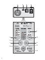
1
STEUERGERÄT FÜR
RGB-LED-SCHEINWERFER
CONTROLLER FOR RGB LED SPOTLIGHTS
CONTRÔLEUR POUR PROJECTEURS RGB À LEDS
CONTROLLER PER PROIETTORI A LED RGB
LED-4MC
Best.-Nr. 38.4370
BEDIENUNGSANLEITUNG • INSTRUCTION MANUAL
MODE D’EMPLOI • ISTRUZIONI PER L’USO • GEBRUIKSAANWIJZING
MANUAL DE INSTRUCCIONES • INSTRUKCJA OBSŁUGI
SIKKERHEDSOPLYSNINGER • SÄKERHETSFÖRESKRIFTER • TURVALLISUUDESTA
1
2
3
4
9
5
10
6
7
11
12
8
13
2
D
A
CH
F
B
CH
Bevor Sie einschalten …
GB
Before switching on …
Wir wünschen Ihnen viel Spaß mit Ihrem neuen
Gerät von „img Stage Line“. Bitte lesen Sie diese
Bedienungsanleitung vor dem Betrieb gründlich
durch. Nur so lernen Sie alle Funktionsmöglichkeiten kennen, vermeiden Fehlbedienungen und
schützen sich und Ihr Gerät vor eventuellen Schäden durch unsachgemäßen Gebrauch. Heben
Sie die Anleitung für ein späteres Nachlesen auf.
We wish you much pleasure with your new “img
Stage Line” unit. Please read these operating
instructions carefully prior to operating the unit.
Thus, you will get to know all functions of the unit,
operating errors will be prevented, and yourself
and the unit will be protected against any damage
caused by improper use. Please keep the operating instructions for later use.
Der deutsche Text beginnt auf der Seite 4.
The English text starts on page 7.
Avant toute installation …
I
Nous vous souhaitons beaucoup de plaisir à utiliser cet appareil “img Stage Line”. Lisez ce mode
dʼemploi entièrement avant toute utilisation. Uniquement ainsi, vous pourrez apprendre lʼensemble des possibilités de fonctionnement de lʼappareil, éviter toute manipulation erronée et vous
protéger, ainsi que lʼappareil, de dommages
éventuels engendrés par une utilisation inadaptée. Conservez la notice pour pouvoir vous y
reporter ultérieurement.
Prima di accendere …
Vi auguriamo buon divertimento con il vostro
nuovo apparecchio di “img Stage Line”. Leggete
attentamente le istruzioni prima di mettere in funzione lʼapparecchio. Solo così potete conoscere
tutte le funzionalità, evitare comandi sbagliati e
proteggere voi stessi e lʼapparecchio da eventuali danni in seguito ad un uso improprio. Conservate le istruzioni per poterle consultare anche
in futuro.
Il testo italiano inizia a pagina 13.
La version française se trouve page 10.
NL
B
Voor u inschakelt …
E
Wij wensen u veel plezier met uw nieuwe apparaat van “img Stage Line”. Lees deze gebruikershandleiding grondig door, alvorens het apparaat
in gebruik te nemen. Alleen zo leert u alle functies
kennen, vermijdt u foutieve bediening en behoedt
u zichzelf en het apparaat voor eventuele schade
door ondeskundig gebruik. Bewaar de handleiding voor latere raadpleging.
Antes de la utilización …
Le deseamos una buena utilización para su nuevo aparato “img Stage Line”. Por favor, lea estas
instrucciones de uso atentamente antes de hacer
funcionar el aparato. De esta manera conocerá
todas las funciones de la unidad, se prevendrán
errores de operación, usted y el aparato estarán
protegidos en contra de todo daño causado por
un uso inadecuado. Por favor, guarde las instrucciones para una futura utilización.
De Nederlandstalige tekst vindt u op pagina 16.
La versión española comienza en la página 19.
PL
Przed uruchomieniem …
DK
Życzymy zadowolenia z nowego produktu “img
Stage Line”. Dzięki tej instrukcji obsługi będą
państwo w stanie poznać wszystkie funkcje tego
urządzenia. Stosując się do instrukcji unikną
państwo błędów i ewentualnego uszkodzenia
urządzenia na skutek nieprawidłowego użytkowania. Prosimy zachować instrukcję.
Før du tænder …
Tillykke med dit nye “img Stage Line” produkt.
Læs sikkerhedsanvisningerne nøje før ibrugtagning, for at beskytte Dem og enheden mod skader, der skyldes forkert brug. Gem manualen til
senere brug.
Sikkerhedsanvisningerne findes på side 26.
Tekst polski zaczyna się na stronie 22.
S
Innan du slår på enheten …
Vi önskar dig mycket glädje med din nya “img
Stage Line” produkt. Läs igenom säkerhetsföreskrifterna innan enheten tas i bruk för att undvika
skador till följd av felaktig hantering. Behåll
instruktionerna för framtida bruk.
Säkerhetsföreskrifterna återfinns på sidan 26.
FIN
Ennen kytkemistä …
Toivomme Sinulle paljon miellyttäviä hetkiä uuden
“img Stage Line” laitteen kanssa. Ennen laitteen
käyttöä pyydämme Sinua huolellisesti tutustumaan turvallisuusohjeisiin. Näin vältyt vahingoilta,
joita virheellinen laitteen käyttö saattaa aiheuttaa.
Ole hyvä ja säilytä käyttöohjeet myöhempää tarvetta varten.
Turvallisuusohjeet löytyvät sivulta 27.
®
w w w.imgstageline.com
3
D
A
Auf der Seite 2 finden Sie alle beschriebenen Bedienelemente und Anschlüsse.
CH
1
Übersicht der Bedienelemente
und Anschlüsse
2
1 DMX-Signal-Ausgang (3-pol. XLR) zum Anschluss
der zu steuernden RGB-LED-Scheinwerfer;
Kontaktbelegung: 1 = Masse, 2 = DMX-, 3 = DMX+
WARNUNG Das Netzgerät wird mit lebensgefährlicher Netzspannung versorgt. Nehmen
Sie deshalb niemals selbst Eingriffe
daran vor! Es besteht die Gefahr eines
elektrischen Schlages.
2 Wahlschalter für die Anzahl der Scheinwerfer
Beachten Sie auch unbedingt die folgenden Punkte:
3 Kleinspannungsbuchse DC IN 12V mit Verriegelung zum Anschluss des mitgelieferten Steckernetzgerätes
G
Verwenden Sie die Geräte nur im Innenbereich und
schützen Sie sie vor Tropf- und Spritzwasser, hoher
Luftfeuchtigkeit und Hitze (zulässiger Einsatztemperaturbereich 0 – 40 °C).
G
Nehmen Sie das Steuergerät nicht in Betrieb oder
ziehen Sie sofort das Netzgerät aus der Steckdose,
1. wenn sichtbare Schäden am Steuergerät oder am
Netzgerät vorhanden sind,
2. wenn nach einem Sturz oder Ähnlichem der Verdacht auf einen Defekt besteht,
3. wenn Funktionsstörungen auftreten.
Geben Sie die Geräte in jedem Fall zur Reparatur in
eine Fachwerkstatt.
7 Taste PTN zur Wahl eines Sequenzmusters im
Sequenzmodus
G
Verwenden Sie für die Reinigung nur ein trockenes,
weiches Tuch, niemals Wasser oder Chemikalien.
8 Taste MODE zum Umschalten der Betriebsart
G
Werden die Geräte zweckentfremdet, falsch angeschlossen, nicht richtig bedient oder nicht fachgerecht repariert, kann keine Haftung für daraus resultierende Sach- oder Personenschäden und keine
Garantie für die Geräte übernommen werden.
4 Ein-/Ausschalter ON/ OFF
5 Taste DIMMER zum Einstellen der Gesamthelligkeit; die aktuelle Einstellung wird über die drei
LEDs „50 %“, „75 %“ und „100 %“ angezeigt
6 Taste TRANSITION zur Wahl der Szenenwechsel
im Sequenzmodus; die aktuelle Einstellung wird
über die beiden LEDs angezeigt
„HARD“ = abrupter Wechsel
„SOFT“ = Überblendung
Statische Farben: LED „SCENE“ leuchtet
Sequenzmodus: LED „SCENE“ leuchtet nicht
9 Mikrofon für den musikgesteuerten Sequenzbetrieb
Sollen die Geräte endgültig aus dem Betrieb
genommen werden, übergeben Sie sie zur
umweltgerechten Entsorgung einem örtlichen Recyclingbetrieb.
10 Taste TAP zum Umschalten zwischen zeitgesteuertem und musikgesteuertem Sequenzbetrieb
11 Taste COL zur Wahl der Farbe oder Farbkombination im statischen Betrieb und im Sequenzbetrieb
12 Taste B/O mit Kontroll-LED zum Dunkelschalten
aller Scheinwerfer (Blackout); zum Zurückschalten
auf den vorherigen Modus die Taste erneut drücken
13 Taste STROBE mit Kontroll-LED „ON“ zum Aktivieren der scheinwerfereigenen Stroboskopfunktion;
zum Zurückschalten auf den vorherigen Modus die
Taste erneut drücken
4
Hinweise für den sicheren Gebrauch
Die Geräte (Steuergerät und Netzgerät) entsprechen
allen erforderlichen Richtlinien der EU und sind deshalb mit
gekennzeichnet.
3
Einsatzmöglichkeiten
Das LED-4MC ist für die einfache Steuerung von
RGB-LED-Scheinwerfern vorgesehen. Es kann die
Modelle PARL-1RGB/… und PARL-10RGB/… steuern und weitere Scheinwerfer, die über die folgende
Belegung der DMX-Kanäle verfügen:
DMX-Wert
Funktion
Kanal 1: Rot-Anteil
0 – 255
Helligkeit Rot
Kanal 2: Grün-Anteil
0 – 255
Helligkeit Grün
Kanal 3: Blau-Anteil
0 – 255
Helligkeit Blau
Kanal 4: Dimmer und Stroboskop
0 – 127
Dimmer
128 – 227
Stroboskop: langsam → schnell
228 – 255
maximale Helligkeit, Stroboskop aus
Ebenso können mit dem LED-4MC Scheinwerferkombinationen mit einer gemeinsamen Steuerung (z. B.
PARL-40SET) oder LED-Panels (z. B. RGBL-110DMX)
bedient werden, wenn darin die einzelnen Scheinwerfer bzw. Segmente jeweils über das gezeigte Kanalschema aufeinanderfolgend steuerbar sind (Scheinwerfer/ Segment 1: Kanal 1 – 4, Scheinwerfer/ Segment
2: Kanal 5 – 8, usw.).
Das Steuergerät kann statische Szenen, d. h. feste
Farben oder Farbkombinationen und wechselnde Szenen (Sequenzen) erzeugen. Die Wechsel der Szenen
einer Sequenz erfolgt nach vorgegebener Zeit oder
durch Musikimpulse über das integrierte Mikrofon. Ob
eine 3er- oder 4er-Scheinwerferkombinationen verwendet wird, kann per Schalter festgelegt werden.
Zusätzlich sind eine Blackout-Funktion und ein Stroboskop-Effekt abrufbar.
4
sprechenden Abschlussstecker (z. B. DLT-123 von
„img Stage Line“) verwenden.
4.2 Anzahl der Scheinwerfer einstellen
D
A
CH
Mit dem Schalter 3-MODE-4 (2) wählen, ob 3 oder 4
Scheinwerfer angeschlossen sind. Entsprechend für
die Steuerung eines PARL-40SET die Position „4“, für
die eines RGBL-110DMX die Position „3“ wählen.
Die Einstellung hat nur Einfluss auf die Art der
Sequenzmuster (z. B. Lauflicht).
4.3 DMX-Adressen einstellen
Bei der Verwendung einzelner Scheinwerfer an diesen
die folgenden DMX-Startadressen einstellen:
1. Scheinwerfer: Startadresse 1
2. Scheinwerfer: Startadresse 5
3. Scheinwerfer: Startadresse 9
4. Scheinwerfer: Startadresse 13
Um weitere Scheinwerfer synchron zu steuern, diese
auf dieselben Startadressen einstellen.
4.4 Stromversorgung anschließen
Das beiliegende Steckernetzgerät mit der Kleinspannungsbuchse DC IN 12V (3) verbinden und in eine
Netzsteckdose (100 – 240 V~/50 – 60 Hz) stecken. Der
Stecker ist in der Buchse gegen versehentliches
Herausziehen verriegelbar. Beim Einstecken den Stecker so halten, dass seine „Ohren“ in die seitlichen
Aussparungen der Buchse passen. Den Stecker zum
Verriegeln nach dem Einstecken 90° im Uhrzeigersinn
drehen.
Inbetriebnahme
4.1 LED-Scheinwerfer anschließen
5
Den Ausgang (1) des Steuergerätes mit dem DMXEingang des ersten RGB-LED-Scheinwerfers verbinden.
Zum Anschluss sollten spezielle Kabel für hohen
Datenfluss verwendet werden. Normale abgeschirmte
Mikrofonkabel mit einem Leitungsquerschnitt von mindestens 2 × 0,22 mm2 und möglichst geringer Kapazität sind nur bei einer Gesamtkabellänge bis 100 m zu
empfehlen. Bei Leitungslängen ab 150 m wird grundsätzlich das Zwischenschalten eines DMX-Aufholverstärkers empfohlen (z. B. SR-103DMX von „img Stage
Line“).
Den DMX-Eingang eines zweiten Scheinwerfers
mit dem Ausgang des ersten Scheinwerfers verbinden. An den Ausgang des zweiten Scheinwerfers den
dritten anschließen usw., bis alle Scheinwerfer in einer
Kette angeschlossen sind.
Den Ausgang des letzten Scheinwerfers für einen
störungsfreien Betrieb mit einem 120-Ω-Abschlusswiderstand (> 0,3 W) versehen: An die Pins 2 und 3
eines XLR-Steckers den Widerstand anlöten und den
Stecker in den DMX-Ausgang stecken oder einen ent-
Das Steuergerät mit dem Schalter ON/ OFF (4) einschalten. Nach dem Einschalten hat das Steuergerät
die zuletzt gewählte Einstellung, wenn diese mindestens 3 s vor dem Ausschalten bestand.
Bedienung
5.1 Statische Farben
1) Leuchtet die LED „SCENE“ unter der Taste MODE
(8) nicht, die Taste drücken, sodass die LED leuchtet.
2) Ist eine der Funktionen B/O oder STROBE aktiv
[die LED unter der Taste (12 oder 13) leuchtet],
diese mit der entsprechenden Taste deaktivieren.
3) Durch (wiederholtes) Drücken der Taste COL (11)
die gewünschte Farbe oder Farbkombination auswählen.
5.2 Sequenzmodus
1) Leuchtet die LED „SCENE“ unter der Taste MODE
(8), die Taste drücken, sodass die LED erlischt.
5
D
A
CH
2) Ist eine der Funktionen B/O oder STROBE aktiv
[die LED unter der Taste (12 oder 13) leuchtet],
diese mit der entsprechenden Taste deaktivieren.
3) Durch (wiederholtes) Drücken der Taste PTN (7)
eines der vorgegebenen Sequenzmuster (z. B. Lauflicht) auswählen.
4) Durch (wiederholtes) Drücken der Taste COL (11)
kann die Farbe oder Farbkombination des gewählten Sequenzmusters geändert werden.
5) Mit der Taste TAP (10) die Art der Sequenzsteuerung auswählen:
1 × drücken:
die Szenen des gewählten Sequenzmusters werden durch ausreichend laute Musikimpulse über
das Mikrofon (9) weitergeschaltet, die LED „S2L“
leuchtet
2) Zum Aktivieren der Stroboskop-Funktion die Taste
STROBE (13) drücken. Die LED „ON“ leuchtet.
Unabhängig von der Einstellung mit der Taste DIMMER (5) blitzen die Scheinwerfer immer mit maximaler Helligkeit (Blitzfrequenz ca. 16 Hz).
3) Zum Deaktivieren die Taste STROBE erneut drücken. Die LED „ON“ erlischt.
Hinweis: Die Stroboskop-Funktion wird nicht im Steuergerät erzeugt, sondern es wird über die Ausgabe
eines bestimmten DMX-Wertes im 4. Kanal jedes
Scheinwerfers die scheinwerfereigene StroboskopFunktion aufgerufen. Verfügt ein Scheinwerfer nicht
über eine entsprechende Funktion, ist so kein Stroboskop-Effekt möglich.
5.5 Blackout-Funktion
2 × drücken (zwischen den Tastendrücken nicht
länger als 1 s warten):
die Szenen des gewählten Sequenzmusters werden automatisch ca. alle 3 Sekunden weitergeschaltet, die LED „S2L“ leuchtet nicht
Mit der Blackout-Funktion können alle Scheinwerfer
vorübergehend dunkelgeschaltet werden.
4 × drücken (oder häufiger, zwischen den Tastendrücken nicht länger als 1 s warten):
die Szenen des gewählten Sequenzmusters werden automatisch im durchschnittlichen Abstand der
Tastendrücke weitergeschaltet, die LED „S2L“
leuchtet nicht
2) Zum Deaktivieren der Funktion die Taste erneut
drücken. Die LED erlischt und der vorherige
Betriebsmodus wird wiederhergestellt.
6) Mit der Taste TRANSITION (6) die Art des Szenenwechsels wählen. Die aktuelle Einstellung wird mit
den LEDs angezeigt:
„HARD“ = abrupter Wechsel
„SOFT“ = Überblendung
Hinweis: Für die Steuerung über das Mikrofon hat
diese Einstellung keine Bedeutung, der Wechsel
erfolgt hier immer abrupt.
1) Zum Aktivieren der Blackout-Funktion die Taste B/O
(12) drücken. Alle Scheinwerfer werden dunkelgeschaltet und die LED unter der Taste leuchtet.
Es ist auch möglich, während der Blackout-Funktion
einen anderen Betriebsmodus auszuwählen, der dann
nach Beenden der Blackout-Funktion aktiv wird.
5.6 Nach dem Gebrauch
Das Steuergerät mit dem Schalter ON/ OFF (4) ausschalten. Bei längerem Nichtgebrauch zur Vermeidung
unnötigen Stromverbrauchs das Steckernetzgerät aus
der Netzsteckdose ziehen.
6
5.3 Gesamthelligkeit wählen
Mit der Taste DIMMER (5) kann die Gesamthelligkeit
gewählt werden. Durch wiederholtes Drücken wird
zwischen „50 %“, „75 %“ und „100 %“ umgeschaltet.
Die drei LEDs zeigen die aktuelle Einstellung an.
Technische Daten
Stromversorgung: . . . 12 V /100 mA über mitgeliefertes Steckernetzgerät
an 100 – 240 V~/50 – 60 Hz
DMX-Kanäle: . . . . . . . 16
Abmessungen: . . . . . . 71 mm × 35 mm × 113 mm
5.4 Stroboskop-Funktion
1) Ist die Funktionen B/O aktiv [die LED unter der
Taste (12) leuchtet], diese mit der Taste deaktivieren.
Gewicht: . . . . . . . . . . . 310 g
Änderungen vorbehalten.
Diese Bedienungsanleitung ist urheberrechtlich für MONACOR ® INTERNATIONAL GmbH & Co. KG geschützt.
Eine Reproduktion für eigene kommerzielle Zwecke – auch auszugsweise – ist untersagt.
6
All operating elements and connections described
can be found on page 2.
2
1
WARNING
Operating Elements and Connections
Safety Notes
1 DMX signal output (3-pole XLR) to connect the
RGB LED spotlights to be controlled;
pin configuration: 1 = ground, 2 = DMX-, 3 = DMX+
The power supply unit uses dangerous
mains voltage. Leave servicing to
skilled personnel only. Inexpert handling or modification of the unit may
result in electric shock.
2 Selector switch for the number of spotlights
Please observe the following items in any case:
3 Low voltage jack DC IN 12V with latching to connect the plug-in power supply unit provided
G
The units are suitable for indoor use only. Protect
them against dripping water and splash water, high
air humidity and heat (admissible ambient temperature range 0 – 40 °C).
G
Do not operate the controller and immediately disconnect the power supply unit from the socket
1. if the controller or the power supply unit is visibly
damaged,
2. if a defect might have occurred after a unit was
dropped or suffered a similar accident,
3. if malfunctions occur.
In any case the units must be repaired by skilled personnel.
7 Button PTN to select a sequence pattern in the
sequence mode
G
For cleaning only use a dry, soft cloth; never use
water or chemicals.
8 Button MODE to select the operating mode
G
No guarantee claims for the units and no liability for
any resulting personal damage or material damage
will be accepted if the units are used for other purposes than originally intended, if they are not correctly connected or operated, or if they are not
repaired in an expert way.
4 ON/OFF switch
5 Button DIMMER to set the total brightness; the current setting will be indicated via the three LEDs
“50 %”, “75 %” and “100 %”
6 Button TRANSITION to select the change of
scenes in the sequence mode; the current setting
will be indicated via the two LEDs
“HARD” = sudden change
“SOFT” = transition
static colours:
GB
The units (controller and power supply unit) correspond to all required directives of the EU and are
therefore marked with .
LED “SCENE” will light up
sequence mode: LED “SCENE” will not light up
9 Microphone for the music-controlled sequence
mode
10 Button TAP to switch between time-controlled and
music-controlled sequence mode
If the units are to be put out of operation
definitively, take them to a local recycling
plant for a disposal which will not be harmful
to the environment.
11 Button COL to select the colour or colour combination in the static mode and in the sequence mode
12 Button B / O with indicating LED for blackout of all
spotlights; to return to the previous mode, press the
button once again
3
13 Button STROBE with indicating LED “ON” to activate the stroboscope function of the spotlight; to
return to the previous mode, press the button once
again
LED-4MC has been designed for easy control of RGB
LED spotlights. It is capable of controlling the models
PARL-1RGB/… and PARL-10RGB/… and further spotlights with the following configuration of DMX channels:
Applications
7
GB
DMX value Function
Channel 1: proportion of red
0 – 255
brightness of red
Channel 2: proportion of green
0 – 255
brightness of green
4.2 Setting the number of spotlights
With the switch 3-MODE-4 (2), define if 3 or 4 spotlights have been connected. Accordingly, select the
position “4” for controlling PARL-40SET or “3” for controlling RGBL-110DMX.
The setting will only affect the type of sequence pattern (e. g. running light).
Channel 3: proportion of blue
0 – 255
brightness of blue
Channel 4: dimmer and stroboscope
0 – 127
dimmer
128 – 227
stroboscope: slow → fast
228 – 255
maximum brightness, stroboscope off
LED-4MC will also be able to operate spotlight combinations with a common control (e. g. PARL-40SET) or
LED panels (e. g. RGBL-110DMX) if they allow successive control of the individual spotlights or segments
via the channel diagram above (spotlight / segment 1:
channels 1 – 4, spotlight / segment 2: channels 5 – 8,
etc.).
The controller will be able to create static scenes, i. e.
fixed colours or colour combinations and changing
scenes (sequences). The scenes of a sequence will
change after a preset time or by music pulses via the
integrated microphone. A selector switch is provided to
define if a combination of 3 or 4 spotlights is used. In
addition, a blackout function and a stroboscope effect
will be available.
4
Setting the Controller in Operation
4.3 Setting DMX addresses
When using individual spotlights, set the following
DMX start addresses on these spotlights:
First spotlight:
start address 1
Second spotlight: start address 5
Third spotlight:
start address 9
Fourth spotlight: start address 13
To synchronize further spotlights, set these spotlights
to the same start addresses.
4.4 Connecting the power supply
Connect the plug-in power supply unit provided to the
low voltage jack DC IN 12V (3) and to a mains socket
(100 – 240 V~/50 – 60 Hz). To prevent accidental disconnection, the plug will latch in the plug. When inserting the plug, hold it in such a way that its “ears” fit into
the lateral recesses of the jack. After inserting, turn the
plug clockwise by 90° to latch it.
5
Operation
Switch on the controller with the switch ON / OFF (4).
After switching on, the controller will have the last setting selected, provided that this setting existed for a
minimum of 3 seconds before the controller was
switched off.
4.1 Connecting LED spotlights
Connect the output (1) of the controller to the DMX
input of the first RGB LED spotlight.
For connection, special cables for high data flow
should be used. Standard microphone cables with
screening and a minimum cross section of 2 × 0.22 mm2
and with a capacity as low as possible can only be recommended for a total cable length of up to 100 m. For
cable lengths exceeding 150 m it is always recommended to insert a DMX level matching amplifier (e. g.
SR-103DMX by “img Stage Line”).
Connect the DMX input of a second spotlight to the
output of the first spotlight. Connect the third spotlight
to the output of the second spotlight etc. until all spotlights have been connected in a chain.
For interference-free operation, terminate the output of the last spotlight with a 120 Ω resistor (> 0.3 W):
Solder the resistor to the pins 2 and 3 of an XLR plug
and connect the plug to the DMX output or use a
corresponding terminating plug (e. g. DLT-123 from
“img Stage Line”).
8
5.1 Static colours
1) If the LED “SCENE” below the button MODE (8)
does not light up, press the button so that the LED
will light up.
2) If one of the functions B / O or STROBE is active [the
LED below the button (12 or 13) will light up], deactivate it with the corresponding button.
3) Press the button COL (11) [repeatedly] to select the
desired colour or colour combination.
5.2 Sequence mode
1) If the LED “SCENE” below the button MODE (8)
lights up, press the button so that the LED will be
extinguished.
2) If one of the functions B/O or STROBE is active [the
LED below the button (12 or 13) will light up], deactivate it with the corresponding button.
3) Press the button PTN (7) [repeatedly] to select one
of the preset sequence patterns (e. g. running light).
4) Press the button COL (11) [repeatedly] to change
the colour or colour combination of the sequence
pattern selected.
3) To deactivate this function, press the button
STROBE once again. The LED “ON” will be extinguished.
5) Press the button TAP (10) to select the type of
sequence control:
Note: The stroboscope function will not be created in
the controller; the individual stroboscope function of
each spotlight will be activated via the output of a particular DMX value in the fourth channel of the spotlight.
If a spotlight is not provided with a corresponding function, no stroboscope effect will be possible.
button pressed once:
the scenes of the sequence pattern selected will
change by music pulses of sufficient volume via the
microphone (9), the LED “S2L” will light up
button pressed twice (do not wait for more than
one second before pressing the button again):
the scenes of the sequence pattern selected will
change automatically approx. every 3 seconds, the
LED “S2L” will not light up
button pressed four times (or more often, do not
wait for more than one second before pressing the
button again):
the scenes of the sequence pattern selected will
change automatically at the average time between
pressing the button, the LED “S2L” will not light up
6) Define the change of scene with the button TRANSITION (6). The LEDs will indicate the current setting:
GB
5.5 Blackout function
With the blackout function, a temporary blackout of all
spotlights will be possible.
1) To activate the blackout function, press the button
B / O (12). A blackout of all spotlights will result and
the LED below the button will light up.
2) To deactivate the function, press the button once
again. The LED will be extinguished and the controller will return to the previous operating mode.
It will also be possible to select another operating
mode during the blackout function. This mode will be
activated after deactivating the blackout function.
“HARD” = sudden change
“SOFT” = transition
5.6 After use
Note: For control via microphone, this setting will
not have any effect; there will always be a sudden
change in this case.
Switch off the controller with the switch ON / OFF (4). If
the controller is not used for a longer period, disconnect the plug-in power supply unit from the mains
socket to prevent unnecessary power consumption.
5.3 Selecting the total brightness
The button DIMMER (5) will define the total brightness.
Press it repeatedly to switch the brightness between
“50 %”, “75 %” and “100 %”. The three LEDs will indicate the current setting.
5.4 Stroboscope function
1) If the function B / O is active [the LED below the button (12) will light up], deactivate it with the button.
2) To activate the stroboscope function, press the button STROBE (13). The LED “ON” will light up.
Regardless of the setting with the button DIMMER
(5), the spotlights will always flash at maximum
brightness (flash frequency: 16 Hz approx.).
6
Specifications
Power supply: . . . . . . 12 V /100 mA via plug-in
power supply unit provided
and connected to
100 – 240 V~/50 – 60 Hz
DMX channels: . . . . . 16
Dimensions: . . . . . . . . 71 mm × 35 mm × 113 mm
Weight: . . . . . . . . . . . 310 g
Subject to technical modification.
All rights reserved by MONACOR ® INTERNATIONAL GmbH & Co. KG. No part of this instruction manual may
be reproduced in any form or by any means for any commercial use.
9
F
B
Vous trouverez page 2, lʼensemble des éléments et
branchements.
CH
1
Eléments et branchements
2
AVERTISSEMENT
Le bloc secteur est alimenté par
une tension dangereuse. Ne touchez jamais lʼintérieur de lʼappareil !
Risque de décharge électrique !
1 Sortie de signal DMX (XLR, 3 pôles) pour brancher
les projecteurs RBG à LEDs à gérer :
pin 1 = masse, 2 = DMX-, 3 = DMX+
2 Sélecteur pour le nombre de projecteurs
3 Prise basse tension DC IN 12V avec verrouillage
pour brancher le bloc secteur livré
Respectez scrupuleusement les points suivants :
G
Les appareils ne sont conçus que pour une utilisation en intérieur. Protégez-les de tout type de projections dʼeau, des éclaboussures, dʼune humidité
élevée dʼair et de la chaleur (plage de température
de fonctionnement autorisée : 0 – 40 °C).
G
Ne faites pas fonctionner le contrôleur ou débranchez immédiatement le bloc secteur du secteur
lorsque :
1. des dommages apparaissent sur le contrôleur ou
le bloc secteur,
2. après une chute ou un cas similaire, vous avez un
doute sur lʼétat de lʼappareil,
3. des dysfonctionnements apparaissent.
Dans tous les cas, les dommages doivent être réparés par un technicien spécialisé.
G
Pour le nettoyage, utilisez uniquement un chiffon
sec et doux, en aucun cas de produits chimiques ou
dʼeau.
G
Nous déclinons toute responsabilité en cas de dommages matériels ou corporels résultants si les appareils sont utilisés dans un but autre que celui pour
lequel ils ont été conçus, sʼils ne sont pas correctement branchés ou utilisés ou sʼils ne sont pas réparés par une personne habilitée, en outre, la garantie
deviendrait caduque.
4 Interrupteur Marche /Arrêt ON / OFF
5 Touche DIMMER pour régler la luminosité totale ; le
réglage actuel est affiché via les trois LEDs “50 %”,
“75 %” et “100 %”.
6 Touche TRANSITION pour sélectionner le changement de scènes en mode séquence : le réglage
actuel est indiqué via les deux LEDs
“HARD” = changement abrupt
“SOFT” = transition souple
7 Touche PTN pour sélectionner un modèle de
séquence en mode séquence
8 Touche MODE pour commuter le mode de fonctionnement :
couleurs statiques : la LED “SCENE” brille
mode séquence :
la LED “SCENE” ne brille pas
9 Microphone pour le mode séquence géré par la
musique
10 Touche TAP pour commuter entre les modes
séquence programmé et géré par la musique
11 Touche COL pour sélectionner la couleur ou la
combinaison de couleurs en mode statique et en
mode séquence
Lorsque les appareils sont définitivement retirés du service, vous devez les déposer dans
une usine de recyclage adaptée pour contribuer à leur élimination non polluante.
12 Touche B / O avec LED de contrôle pour couper tous
les projecteurs (Blackout) ; pour revenir au mode
précédent, appuyez une nouvelle fois sur la
touche.
13 Touche STROBE avec LED de contrôle “ON” pour
activer la fonction stroboscope propre à chaque
projecteur : pour revenir au mode précédent,
appuyez une nouvelle fois sur la touche.
10
Conseils dʼutilisation et de sécurité
Les appareils (contrôleur et bloc secteur) répondent à
toutes les directives nécessaires de lʼUnion européenne et portent donc le symbole .
3
Possibilités dʼutilisation
Le LED-4MC est prévu pour une gestion simple de
projecteurs RGB à LEDs. Il peut gérer les modèles
PARL-1RGB /... et PARL-10RGB /... et dʼautres projecteurs disposant de la configuration de canaux DMX
suivante :
Valeur DMX Fonction
canal 1 : part de rouge
0 – 255
luminosité rouge
canal 2 : part de vert
0 – 255
luminosité vert
canal 3 : part de bleu
0 – 255
4.2 Réglage du nombre de projecteurs
Avec le sélecteur 3-MODE-4 (2) sélectionnez si 3 ou 4
projecteurs sont reliés ; pour contrôler un PARL40SET, sélectionnez la position “4”, pour contrôler un
RGBL-110DMX, la position “3”.
Le réglage influe uniquement sur le type de
modèles de séquence (par exemple lumière défilante).
B
CH
luminosité bleu
canal 4 : dimmer et stroboscope
0 – 127
dimmer
128 – 227
stroboscope : lent → rapide
228 – 255
luminosité maximale, stroboscope éteint
De même, on peut utiliser avec le LED-4MC des combinaisons de projecteurs avec une gestion commune
(par exemple PARL-40SET) ou des panneaux à LEDs
(par exemple RGBL-110DMX) sʼils permettent un
contrôle successif de chaque projecteur ou panneau
selon le schéma de canal indiqué (projecteur / segment
1 : canaux 1 – 4, projecteur / segment 2 : canaux 5 – 8,
et ainsi de suite).
Le contrôleur peut créer des scènes statiques, cʼest-àdire des couleurs ou des combinaisons de couleurs
fixes et des scènes changeantes (séquences). Les
changements de scènes dʼune séquence sʼeffectuent
après une durée programmée ou par des impulsions
de musique via le microphone intégré. Un sélecteur
est prévu pour définir si on utilise une combinaison de
trois ou quatre projecteurs. On peut également activer
une fonction Blackout et un effet stroboscope.
4.3 Réglage des adresses DMX
Si vous utilisez des projecteurs individuels, réglez-les
avec les adresses DMX de démarrage suivantes :
projecteur 1 : adresse de démarrage 1
projecteur 2 : adresse de démarrage 5
projecteur 3 : adresse de démarrage 9
projecteur 4 : adresse de démarrage 13
Pour gérer dʼautres projecteurs de manière synchrone, réglez-les sur les mêmes adresses de démarrage.
4.4 Branchement de lʼalimentation
Reliez le bloc secteur livré à la prise basse tension
DC IN 12V (3) et à une prise secteur 100 – 240 V~ /
50 – 60 Hz. La fiche est verrouillable dans la prise pour
empêcher quʼelle ne soit retirée par inadvertance.
Lorsque vous branchez la fiche, tenez-la de telle sorte
que ses “oreilles” rentrent dans les encoches latérales
de la prise. Une fois insérée, tournez la fiche de 90°
dans le sens des aiguilles dʼune montre pour la verrouiller.
5
4
F
Fonctionnement
4.1 Branchement des projecteurs à LEDs
Reliez la sortie (1) du contrôleur à lʼentrée DMX du
premier projecteur RGB à LEDs.
Pour le branchement, il est recommandé dʼutiliser
des câbles spécifiques pour des flots importants de
données. Des câbles micro usuels avec un blindage et
une section minimum de 2 × 0,22 mm2 et une capacité
la plus faible possible ne peuvent être recommandés
que pour des longueurs de câble de 100 m maximum.
Pour des longueurs de liaison à partir de 150 m, il est
recommandé dʼinsérer un amplificateur DMX de signal
(par exemple SR-103DMX de “img Stage Line”).
Reliez lʼentrée DMX du deuxième projecteur à la
sortie du premier. Reliez le troisième projecteur à la
sortie du deuxième et ainsi de suite jusquʼà ce que
tous les projecteurs soient reliés en une chaîne.
Pour un fonctionnement sans interférences, placez
à la sortie du dernier projecteur une résistance terminale 120 Ω (> 0,3 W) : soudez la résistance aux pins 2
et 3 dʼune fiche XLR et branchez la fiche à la sortie
DMX ou utilisez un bouchon correspondant (par exemple DLT-123 de “img Stage Line”).
Utilisation
Allumez le contrôleur avec lʼinterrupteur ON / OFF (4).
Une fois allumé, le contrôleur propose le dernier
réglage sélectionné lorsque ce dernier était actif
3 secondes au moins avant lʼarrêt.
5.1 Couleurs statiques
1) Si la LED “SCENE” sous la touche MODE (8) ne
brille pas, appuyez sur la touche pour que la LED
brille.
2) Si une des fonctions B / O ou STROBE est activé [la
LED sous la touche (12 ou 13) brille], désactivezla avec la touche correspondante.
3) Par une pression (répétée) sur la touche COL (11),
sélectionnez la couleur ou la combinaison de couleurs souhaitée.
5.2 Mode séquence
1) Si la LED “SCENE” sous la touche MODE (8) brille,
appuyez sur la touche pour que la LED sʼéteigne.
2) Si une des fonctions B / O ou STROBE est activé
[la LED sous la touche (12 ou 13) brille], désactivez-la avec la touche correspondante.
11
F
B
CH
3) Par une pression (répétée) sur la touche PTN (7),
sélectionnez un des modèles de séquence proposés (par exemple lumière défilante).
4) Par une pression (répétée) sur la touche COL (11),
sélectionnez la couleur ou la combinaison de couleurs du modèle de séquence choisi.
5) Avec la touche TAP (10), sélectionnez le type de
gestion des séquences :
1 × pression :
les scènes du modèle de séquence choisi sont
changées par des impulsions de musique suffisamment fortes via le micro (9) ; la LED “S2L” brille
2 × pression (entre chaque pression, ne pas attendre plus de 1 seconde) :
les scènes du modèle de séquence choisi sont
changées automatiquement toutes les trois
secondes environ, la LED “S2L” ne brille pas
4 × pression (ou davantage, entre chaque pression, ne pas attendre plus de 1 seconde) :
les scènes du modèle de séquence choisi sont
changées automatiquement à intervalle moyen des
activations de la touche, la LED “S2L” ne brille pas.
6) Avec la touche TRANSITION (6), sélectionnez le
type de changement de scène. Le réglage actuel
est indiqué par les LEDs :
damment du réglage effectué avec la touche DIMMER (5), les projecteurs émettent des éclairs toujours avec une luminosité maximale (fréquence des
éclairs 16 Hz environ).
3) Pour désactiver la fonction, appuyez une nouvelle
fois sur la touche STROBE, la LED “ON” sʼéteint.
Remarque : La fonction stroboscope nʼest pas créée
dans le contrôleur, la fonction stroboscope propre à
chaque projecteur est activée via lʼémission dʼune
valeur DMX donnée dans le canal 4 de chaque projecteur ; si le projecteur ne dispose pas de fonction correspondante, aucun effet stroboscope nʼest possible.
5.5 Fonction Blackout
Avec la fonction Blackout, tous les projecteurs peuvent
être coupés temporairement.
1) Pour activer la fonction Blackout, appuyez sur la
touche B / O (12). Tous les projecteurs sont coupés,
la LED sous la touche brille.
2) Pour désactiver la fonction, appuyez une nouvelle
fois sur la touche. La LED sʼéteint, le mode de fonctionnement précédent est rétabli.
Il est également possible de sélectionner un autre
mode de fonctionnement pendant la fonction Blackout,
il est actif une fois la fonction Blackout désactivée.
“HARD” = changement abrupt
“SOFT” = transition souple
5.6 Après utilisation
Remarque : Pour une gestion via le microphone,
ce réglage nʼa pas dʼimportance, le changement
sʼeffectue toujours de manière abrupte.
Eteignez le contrôleur avec lʼinterrupteur ON / OFF (4).
En cas de non utilisation prolongée, débranchez le
bloc secteur de la prise secteur pour éviter toute
consommation inutile.
5.3 Sélection de la luminosité totale
Avec la touche DIMMER (5), vous pouvez sélectionner
la luminosité totale. Par une pression répétée, vous
pouvez commuter entre une luminosité de “50 %”,
“75 %” ou “100 %”. Les trois LEDs indiquent le réglage
actuel.
6
Caractéristiques techniques
Alimentation : . . . . . . . 12 V /100 mA par bloc secteur
livré relié au secteur
100 – 240 V~/50 – 60 Hz
Canaux DMX : . . . . . . 16
5.4 Fonction stroboscope
Dimensions : . . . . . . . 71 mm × 35 mm × 113 mm
1) Si la fonction B / O est activée [la LED sous la touche
(12) brille], désactivez-la avec la touche correspondante.
Poids : . . . . . . . . . . . . 310 g
2) Pour activer la fonction stroboscope, appuyez sur la
touche STROBE (13). La LED “ON” brille. Indépen-
Tout droit de modification réservé.
Notice dʼutilisation protégée par le copyright de MONACOR ® INTERNATIONAL GmbH & Co. KG. Toute reproduction même partielle à des fins commerciales est interdite.
12
A pagina 2 trovate tutti gli elementi di comando e
collegamenti descritti.
1
Elementi di comando
e collegamenti
2
AVVERTIMENTO
1 Uscita dei segnali DMX (XLR a 3 poli) per il collegamento dei proiettori a LED RGB da comandare;
piedinatura: 1 = massa, 2 = DMX-, 3 = DMX+
2 Selettore per il numero dei proiettori
3 Presa alimentazione DC IN 12V con blocco per il
collegamento del alimentatore a spina in dotazione
5 Tasto DIMMER per regolare la luminosità globale;
lʼimpostazione attuale è indicata tramite tre LED
“50 %”, “75 %” e “100 %”
= cambio improvviso
= dissolvenza
7 Tasto PTN per la scelta di un disegno nel modo
sequenziale
Usare gli apparecchi solo allʼinterno di locali e proteggerli dallʼacqua gocciolante e dagli spruzzi dʼacqua, da alta umidità dellʼaria e dal calore (temperatura dʼimpiego ammessa fra 0 e 40 °C).
G
Non mettere in funzione il controller e staccare
subito lʼalimentatore dalla rete se:
1. il controller o lʼalimentatore presentano dei danni
visibili;
2. dopo una caduta o dopo eventi simili sussiste il
sospetto di un difetto;
3. gli apparecchi non funzionano correttamente.
Per la riparazione rivolgersi sempre ad unʼofficina
competente.
G
Per la pulizia usare solo un panno morbido, asciutto;
non impiegare in nessun caso prodotti chimici o
acqua.
G
Nel caso dʼuso improprio, di collegamenti sbagliati,
dʼimpiego scorretto o di riparazione non a regola
dʼarte degli apparecchi, non si assume nessuna
responsabilità per eventuali danni consequenziali a
persone o a cose e non si assume nessuna garanzia per gli apparecchi.
8 Tasto MODE per cambiare il modo di funzionamento
colori statici:
è acceso il LED “SCENE”
modo sequenziale: è spento il LED “SCENE”
9 Microfono per il funzionamento
comandato dalla musica
Lʼalimentatore funziona con pericolosa tensione di rete. Non intervenire mai personalmente al suo
interno! Esiste il pericolo di una scarica elettrica.
G
6 Tasto TRANSITION per la scelta del cambio scenari nel modo sequenziale; lʼimpostazione attuale è
indicata tramite i due LED
“SOFT”
I
Si devono osservare assolutamente anche i seguenti
punti:
4 Interruttore ON / OFF
“HARD”
Avvertenze di sicurezza
Gli apparecchi (controller e alimentatore) sono conformi a tutte le direttive richieste dellʼUE e pertanto portano la sigla .
sequenziale
10 Tasto TAP per cambiare fra funzionamento
sequenziale comandato dal tempo o dalla musica
Se si desidera eliminare gli apparecchi definitivamente, consegnarli per lo smaltimento ad
unʼistituzione locale per il riciclaggio.
11 Tasto COL per la scelta del colore o della combinazione di colori nel funzionamento statico e sequenziale
12 Tasto B / O con LED di controllo per oscurare tutti i
proiettori (blackout); per ritornare al modo precedente premere il tasto nuovamente
3
13 Tasto STROBE con LED di controllo “ON” per attivare la funzione stroboscopica propria dei proiettori; per ritornare al modo precedente premere il
tasto nuovamente
Il LED-4MC è previsto per un comando semplice di
proiettori a LED RGB. È in grado di pilotare i modelli
PARL-1RGB /… e PARL-10RGB /… nonché altri proiettori con la seguenti impostazione dei canali DMX:
Possibilità dʼimpiego
13
I
Valore DMX Funzione
Canale 1: Parte di rosso
0 – 255
Luminosità rosso
Canale 2: Parte di verde
0 – 255
Luminosità verde
Canale 3: Parte di blu
0 – 255
Luminosità blu
Canale 4: Dimmer e stroboscopio
0 – 127
Dimmer
128 – 227
Stroboscopio: lento → veloce
228 – 255
Luminosità massima, stroboscopio spento
Il LED-4MC può servire anche per combinazioni di proiettori con un comando comune (p. es. PARL-40SET)
oppure per pannelli di LED (p. es. RGBL-110DMX), se
i singoli proiettori o segmenti sono comandabili uno
dopo lʼaltro secondo lo schema dei canali segnalato
sopra (proiettore / segmento 1: canale 1 – 4, proiettore /
segmento 2: canale 5 – 8, ecc.).
Il controller è in grado di generare scenari statici, cioè
colori o combinazioni di colori fissi e scenari
(sequenze) che cambiano. Il cambio degli scenari di
una sequenza avviene secondo un tempo stabilito o
tramite gli impulsi di musica attraverso il microfono
integrato. Con un interruttore si può stabilire se usare
una combinazione di 3 o 4 proiettori. In più sono disponibili una funzione blackout e un effetto stroboscopico.
4.2 Impostare il numero dei proiettori
Con il selettore 3-MODE-4 (2) scegliere se collegare 3
o 4 proiettori. Corrispondentemente, per il comando di
un PARL-40SET scegliere la posizione “4”, e per un
RGBL-110DMX la posizione “3”.
Questa impostazione ha effetto solo sul tipo dei
disegni di un sequenza (p. es. luci a scorrimento).
4.3 Impostare gli indirizzi DMX
Usando singoli proiettori, impostare i seguenti indirizzi
di start DMX:
1. proiettore: indirizzo di start 1
2. proiettore: indirizzo di start 5
3. proiettore: indirizzo di start 9
4. proiettore: indirizzo di start 13
Per comandare ulteriori proiettori in modo sincrono,
impostare per loro gli stessi indirizzi.
4.4 Collegare lʼalimentazione
Collegare lʼalimentatore a spina in dotazione con la
presa dʼalimentazione DC IN 12V (3) e inserirlo in una
presa di rete (100 – 240 V~/50 – 60 Hz). Il connettore
può essere bloccato nella presa per escludere che
venga staccato accidentalmente. Inserendo il connettore, tenerlo in modo tale che le sue “orecchie” entrino
negli incavi laterali. Per bloccarlo, dopo averlo inserito
girarlo di 90° in senso orario.
5
4
Messa in funzione
4.1 Collegare i proiettori a LED
Collegare lʼuscita (1) del controllore con lʼingresso
DMX del primo proiettore a LED RGB.
Per il collegamento si dovrebbero usare cavi per un
forte flusso di dati. Lʼimpiego di normali cavi schermati
per microfoni di sezione minima di 2 × 0,22 mm2 e con
capacità possibilmente bassa è consigliabile solo nel
caso di una lunghezza complessiva inferiore a 100 m.
Nel caso di lunghezze oltre i 150 m si consiglia lʼimpiego di un amplificatore DMX (p. es. SR-103DMX di
“img Stage Line”).
Collegare lʼingresso DMX di un secondo proiettore
con lʼuscita del primo proiettore. Collegare il terzo proiettore con lʼuscita del secondo proiettore ecc. finché
tutti i proiettori sono collegati formando una catena.
Per un funzionamento senza disturbi, terminare
lʼuscita dellʼultimo proiettore con una resistenza di
120 Ω (> 0,3 W): saldare la resistenza ai pin 2 e 3 di un
connettore XLR e inserire il connettore nellʼuscita DMX
oppure usare un terminatore adatto (p. es. DLT-123 di
“img Stage Line”).
14
Funzionamento
Accendere il controller con lʼinterruttore ON / OFF (4).
Dopo lʼaccensione, il controller si trova con lʼimpostazione scelta per ultima, se questa era rimasta attiva
per lo meno per 3 secondi prima dello spegnimento.
5.1 Colori statici
1) Se il LED “SCENE” sotto il tasto MODE (8) è
spento, premere il tasto in modo che il LED si
accenda.
2) Se una delle funzioni B / O o STROBE è attiva [il
LED sotto il tasto (12 o 13) è acceso], disattivarla
con il relativo tasto.
3) Premendo (ripetutamente) il tasto COL (11), scegliere il colore o la combinazione di colori.
5.2 Modo sequenziale
1) Se il LED “SCENE” sotto il tasto MODE (8) è
acceso, premere il tasto in modo che il LED si
spenga.
2) Se una delle funzioni B / O o STROBE è attiva [il
LED sotto il tasto (12 o 13) è acceso], disattivarla
con il relativo tasto.
3) Premendo (ripetutamente) il tasto PTN (7), scegliere un disegno per la sequenza (p. es. luci a scorrimento).
pendentemente dallʼimpostazione con il tasto DIMMER (5), i proiettori lampeggiano sempre con la
luminosità massima (frequenza del lampi 16 Hz ca.).
4) Premendo (ripetutamente) il tasto COL (11), si può
modificare il colore o la combinazione di colori del
disegno selezionato.
3) Per disattivare premere nuovamente il tasto
STROBE. Il LED “ON” si spegne.
5) Con il tasto TAP (10) scegliere il modo del comando
sequenziale:
premere 1 ×:
gli scenari del disegno selezionato cambiando
secondo gli impulsi di musica sufficientemente forti
tramite il microfono (9), il LED “S2L” è acceso
premere 2 × (fra due pressioni del tasto non far
passare più di 1 sec.):
gli scenari del disegno selezionato cambiando
automaticamente ca. ogni 3 secondi, il LED “S2L” è
spento
premere 4 × (o più volte, fra due pressioni del tasto
non far passare più di 1 sec.):
gli scenari del disegno selezionato cambiando
automaticamente secondo gli intervalli medi fra le
pressioni dei tasti, il LED “S2L” è spento
6) Con il tasto TRANSITION (6) determinare il tipo del
cambio scenario. Lʼimpostazione attuale è visualizzata con i LED:
“HARD” = cambio improvviso
“SOFT” = dissolvenza
Nota: Questa impostazione è senza importanza
per il comando attraverso il microfono; in questo
caso, il cambio è sempre un cambio improvviso.
I
Nota: La funzione stroboscopica non viene generata
nel controller; la funzione stroboscopica propria ad
ogni proiettore viene chiamata tramite un determinato
valore DMX nel 4. canale di ogni proiettore. Se un proiettore non dispone di quella funzione, lʼeffetto stroboscopico non è possibile.
5.5 Funzione blackout
Con la funzione blackout è possibile oscurare temporaneamente tutti i proiettori.
1) Per attivare la funzione blackout, premere il tasto
B/ O (12). Tutti i proiettori saranno oscurati e il LED
sotto il tasto è acceso.
2) Per disattivare la funzione, premere nuovamente il
tasto. Il LED si spegne, e si ritorna nel modo precedente di funzionamento.
È possibile scegliere un altro modo di funzionamento
durante la funzione di blackout; tale modo sarà attivo
dopo la disattivazione del blackout.
5.6 Dopo lʼuso
Spegnere il controller con lʼinterruttore ON / OFF (4). In
caso di non-utilizzo prolungato, conviene staccare lʼalimentatore dalla presa per evitare un consumo inutile
dʼenergia.
5.3 Scegliere la luminosità globale
Con il tasto DIMMER (5) si può scegliere la luminosità
globale. Con pressioni ripetute, si cambia fra “50 %”,
“75 %” e “100 %”. I tre LED indicano lʼattuale impostazione.
6
Dati tecnici
Alimentazione: . . . . . . 12 V /100 mA tramite alimentatore a spina in dotazione
con 100 – 240 V~/50 – 60 Hz
Canali DMX: . . . . . . . 16
5.4 Funzione stroboscopica
Dimensioni: . . . . . . . . 71 mm × 35 mm × 113 mm
1) Se la funzione B/O è attiva [il LED sotto il tasto (12)
è acceso], disattivarla con il tasto.
Peso: . . . . . . . . . . . . . 310 g
2) Per attivare la funzione stroboscopica, premere il
tasto STROBE (13). Il LED “ON” si accende. Indi-
Con riserva di modifiche tecniche.
La MONACOR ® INTERNATIONAL GmbH & Co. KG si riserva ogni diritto di elaborazione in qualsiasi forma delle
presenti istruzioni per lʼuso. La riproduzione – anche parziale – per propri scopi commerciali è vietata.
15
NL
B
Op pagina 2 vindt u een overzicht van alle bedieningselementen en de aansluitingen.
1
Overzicht van bedieningselementen
en aansluitingen
2
WAARSCHUWING
De netspanning van de netadapter
is levensgevaarlijk. Open het apparaat daarom nooit zelf! U loopt het
risico van een elektrische schok.
1 DMX-signaaluitgang (3-pol. XLR) voor de aansluiting op de te sturen LED-schijnwerper;
penconfiguratie: 1 = massa, 2 = DMX-, 3 = DMX+
2 Keuzeschakelaar voor het aantal schijnwerpers
Let eveneens op het volgende:
3 Laagspanningsjack DC IN 12V met vergrendeling
voor aansluiting van de bijgeleverde netadapter
G
De apparaten zijn uitsluitend geschikt voor gebruik
binnenshuis. Vermijd druip- en spatwater, plaatsen
met een hoge vochtigheid en uitzonderlijk warme
plaatsen (toegestaan omgevingstemperatuurbereik:
0 – 40 °C).
G
Schakel het besturingsapparaat niet in en trek de
netadapter onmiddellijk uit het stopcontact,
1. wanneer het besturingsapparaat of de netadapter
zichtbaar beschadigd zijn,
2. wanneer er een defect zou kunnen optreden
nadat het apparaat bijvoorbeeld is gevallen,
3. wanneer het apparaat slecht functioneert.
De toestellen moeten in elk geval hersteld worden
door een gekwalificeerd vakman.
G
Verwijder het stof met een droge, zachte doek.
Gebruik zeker geen water of chemicaliën.
G
In geval van ongeoorloofd of verkeerd gebruik, verkeerde aansluiting, foutieve bediening of van herstelling door een niet-gekwalificeerd persoon vervalt
de garantie en de aansprakelijkheid voor hieruit
resulterende materiële of lichamelijke schade.
4 POWER-schakelaar ON / OFF
5 Toets DIMMER voor het instellen van de totale helderheid; de huidige instelling wordt aangeduid aan
de hand van de drie LEDʼs “50 %”, “75 %” en
“100 %”
6 Toets TRANSITION voor het selecteren van de
scènewissel in de sequentiemodus; de huidige
instelling wordt via de beide LEDʼs weergegeven
“HARD” = abrupte wissel
“SOFT” = overgang
7 Toets PTN voor het selecteren van een sequentiepatroon in de sequentiemodus
8 Toets MODE om de modus te wijzigen
Statische kleuren: LED “SCENE” licht op
Sequentiemodus: LED “SCENE” licht niet op
9 Microfoon voor het muziekgestuurde sequentiebedrijf
10 Toets TAP voor het omschakelen tussen het tijdgestuurde en muziekgestuurde sequentiebedrijf
Wanneer de apparaten definitief uit bedrijf
worden genomen, bezorg ze dan voor verwerking aan een plaatselijk recyclagebedrijf.
11 Toets COL voor het selecteren van de kleur of kleurencombinatie in het statische bedrijf en in het
sequentiebedrijf
12 Toets B / O met controle-LED voor het dimmen van
alle schijnwerpers (blackout); om terug naar de
SOUND-modus te schakelen, drukt u opnieuw op
de toets
13 Toets STROBE met controle-LED “ON” voor het
activeren van de schijnwerpereigen stroboscoopfunctie; om terug naar de SOUND-modus te schakelen, drukt u opnieuw op de toets
16
Veiligheidsvoorschriften
De apparaten (besturingsapparaat en netadapter) zijn
allemaal in overeenstemming met alle EU-Richtlijnen
en dragen daarom het -kenmerk.
3
Toepassingen
De LED-4MC is ontworpen voor de eenvoudige regeling van RGB-LED-schijnwerpers. Hij kan de modellen
PARL-1RGB/… en PARL-10RGB/… regelen en bijkomende schijnwerpers die via de volgende configuratie
van de DMX-kanalen beschikken:
DMX-waarde Functie
Kanaal 1: Roodaandeel
0 – 255
Helderheid rood
Kanaal 2: Groenaandeel
0 – 255
Helderheid groen
Kanaal 3: Blauwaandeel
0 – 255
Selecteer met de schakelaar 3-MODE-4 (2) of er drie
of vier schijnwerpers zijn aangesloten. Zo selecteert u
voor het regelen van een PARL-40SET de positie “4”;
voor de regeling van een RGBL-110DMX selecteert u
de positie “3”.
De instelling heeft alleen invloed op de aard van het
sequentiepatroon (b.v. looplicht).
NL
B
Helderheid blauw
Kanaal 4: Dimmer en stroboscoop
0 – 127
Dimmer
128 – 227
Stroboscoop: langzaam → snel
228 – 255
maximale helderheid, stroboscoop uit
U kunt met de LED-4MC ook schijnwerpercombinaties
met een gemeenschappelijke besturing (b.v. PARL40SET) of LED-paneel (b.v. RGBL-110DMX) bedienen, als hierbij de individuele schijnwerpers of segmenten elk via het weergegeven kanaalschema
regelbaar zijn (schijnwerper/ segment 1: kanaal 1 – 4,
schijnwerpers / segment 2: kanaal 5 – 8 etc.).
De controller kan statische scènes, d.w.z. vaste kleuren of kleurcombinaties, en wisselende scènes
(sequenties) genereren. Het wisselen van de scènes
van een sequentie gebeurt na vastgelegde tijd of door
muziekimpulsen via de ingebouwde microfoon. Of er
een combinatie van drie of vier schijnwerpers wordt
gebruikt, kunt u via schakelaar vastleggen. Bovendien
kunt u een blackoutfunctie en een stroboscoopeffect
oproepen.
4
4.2 Aantal schijnwerpers instellen
Ingebruikneming
4.1 LED-schijnwerper aansluiten
Verbind de uitgang (1) van de controller met de DMXingang van de eerste -LED-schijnwerper.
Voor de aansluiting moeten speciale kabels voor
hoge gegevensstromen worden gebruikt. Normale
afgeschermde microfoonkabels met een leidingdiameter van ten minste 2 × 0,22 mm2 en een zo gering mogelijke capaciteit zijn alleen bij een totale kabellengte tot
100 m aan te bevelen. Bij kabellengten vanaf 150 m
wordt in principe aanbevolen om een DMX-ophaalversterker tussen te schakelen (b.v. SR-103DMX van “img
Stage Line”).
Verbind de DMX-ingang van een tweede schijnwerper met de uitgang van de eerste schijnwerper. Sluit op
de uitgang van de tweede schijnwerper de derde aan
etc. tot alle schijnwerpers in een ketting zijn aangesloten.
Voorzie op de uitgang van de laatste schijnwerper
een afsluitweerstand van 120 Ω (> 0,3 W) voor een
storingvrije werking: Soldeer de weerstand vast op de
pinnen 2 en 3 van een XLR-stekker en plug de stekker
in de DMX-uitgang, of gebruik een overeenkomstige
afsluitstekker (b.v. DLT-123 van “img Stage Line”).
4.3 DMX-adressen instellen
Bij het gebruik van individuele schijnwerpers stelt u op
de schijnwerpers de volgende DMX-startadressen in:
1ste schijnwerper: Startadres 1
2de schijnwerper: Startadres 5
3de schijnwerper: Startadres 9
4de schijnwerper: Startadres 13
Om bijkomende schijnwerpers synchroon te regelen,
moet u deze instellen op hetzelfde startadres.
4.4 Voedingsspanning aansluiten
Verbind de bijgeleverde netadapter met de laagspanningsjack DC IN 12V (3) en plug hem in een stopcontact (100 – 240 V~/50 – 60 Hz). De stekker kan in de
jack worden vergrendeld tegen onbedoeld uittrekken.
Bij het insteken houdt u de stekker zo dat de “oren”
ervan in de zijdelingse uitsparingen van de jack passen. Draai de stekker na het insteken 90° naar rechts
om hem te vergrendelen.
5
Bediening
Schakel de controller in met de schakelaar ON / OFF
(4). Na het inschakelen neemt de controller de instelling over die het laatst werd geselecteerd, als deze
minstens 3 seconden vóór het uitschakelen bestond.
5.1 Statische kleuren
1) Als de LED “SCENE” onder de toets MODE (8) niet
oplicht, druk dan op de toets zodat de LED oplicht.
2) Als een van de functies B / O of STROBE actief is
[de LED onder de toets (12 of 13) licht op], schakelt
u deze uit met de overeenkomstige toets.
3) Selecteer de gewenste kleur of kleurcombinatie
door (herhaalde keren) op de toets COL (11) te
drukken.
5.2 Sequentiemodus
1) Als de LED “SCENE” onder de toets MODE (8)
oplicht, druk dan op de toets zodat de LED niet
oplicht.
2) Als een van de functies B / O of STROBE actief is
[de LED onder de toets (12 of 13) licht op], schakelt
u deze uit met de overeenkomstige toets.
17
NL
B
3) Selecteer een van de opgegeven sequentiepatronen (b.v. looplicht) door (herhaalde keren) op de
toets PTN (7) te drukken.
hankelijk van de instelling met de toets DIMMER (5)
lichten de schijnwerpers steeds met maximale helderheid op (flitsfrequentie ca. 16 Hz).
4) Door (herhaalde keren) op de toets COL (11) te
drukken, kunt u de kleur of kleurcombinatie van het
geselecteerde sequentiepatroon wijzigen.
3) Voor deactiveren drukt u opnieuw op de toets
STROBE. De LED “ON” gaat uit.
5) Selecteer met de toets TAP (10) het type sequentieregeling:
1 × drukken:
de scènes van het geselecteerde sequentiepatroon
worden door voldoende luide muziekimpulsen via
de microfoon (9) verder geschakeld, de LED “S2L”
licht op
2 × drukken (wacht tussen het drukken op de toets
niet langer dan 1 seconde):
de scènes van het geselecteerde sequentiepatroon
worden automatisch ca. om de drie seconden verder geschakeld, de LED “S2L” licht niet op
4 × drukken (of meer; wacht tussen het drukken op
de toets niet langer dan 1 seconde):
de scènes van het geselecteerde sequentiepatroon
worden automatisch volgens het gemiddelde interval van het drukken op de toets verder geschakeld,
de LED “S2L” licht niet op
6) Selecteer met de toets TRANSITION (6) het type
scènewissel. De huidige instelling wordt met de
LEDʼs weergegeven:
“HARD” = abrupte wissel
“SOFT” = overgang
Opmerking: Voor de besturing via de microfoon
heeft deze instelling geen belang, het wisselen
gebeurt hier steeds abrupt.
Opmerking: De stroboscoopfunctie wordt niet in de
controller gegenereerd, maar via het uitvoeren van
een bepaalde DMX-waarde wordt in het vierde kanaal
van elke schijnwerper de bijbehorende stroboscoopfunctie opgeroepen. Als een schijnwerper niet over
een overeenkomstige functie beschikt, is zo geen stroboscoopeffect mogelijk.
5.5 De blackoutfunctie
Met de blackoutfunctie kunnen alle schijnwerpers tijdelijk worden gedimd.
1) Om de blackoutfunctie te activeren, drukt u op de
toets B / O (12). Alle schijnwerpers worden gedimd
en de LED onder de toets licht op.
2) Om de functie uit te schakelen, drukt u opnieuw op
de toets. De LED gaat uit en de vorige bedrijfsmodus wordt hersteld.
Het is ook mogelijk om tijdens de blackoutfunctie een
andere bedrijfsmodus te selecteren die dan na het
beëindigen van de blackoutfunctie actief wordt.
5.6 Na het gebruik
Schakel de controller uit met de schakelaar ON / OFF
(4). Als het apparaat langere tijd niet wordt gebruikt,
haalt u de netadapter uit het stopcontact om onnodig
stroomverbruik te vermijden.
5.3 Totale helderheid selecteren
6
Met de toets DIMMER (5) kunt u de totale helderheid
selecteren. Door herhaalde keren te drukken, kunt u
omschakelen tussen “50 %”, “75 %” en “100 %”. De
drie LEDʼs geven de huidige instelling aan.
Voedingsspanning: . . 12 V /100 mA via meegeleverde netadapter
op 100 – 240 V~/50 – 60 Hz
Technische gegevens
DMX-kanalen: . . . . . . 16
Afmetingen: . . . . . . . . 71 mm × 35 mm × 113 mm
5.4 Stroboscoopfunctie
1) Als de functie B/O actief is [de LED onder de toets
(12) licht op], schakelt u deze met de toets uit.
2) Om de stroboscoopfunctie te activeren, drukt u op
de toets STROBE (13). De LED “ON” licht op. Onaf-
Gewicht: . . . . . . . . . . . 310 g
Wijzigingen voorbehouden.
Deze gebruiksaanwijzing is door de auteurswet beschermde eigendom van MONACOR ® INTERNATIONAL
GmbH & Co. KG. Een reproductie – ook gedeeltelijk – voor eigen commerciële doeleinden is verboden.
18
Todos los elementos de funcionamiento y las
conexiones que se describen pueden encontrarse
en la página 2.
2
1
ADVERTENCIA El alimentador utiliza un voltaje de
corriente peligroso. Deje el mantenimiento en manos del personal cualificado. El manejo inexperto o la modificación del aparato pueden provocar
una descarga.
Elementos de Funcionamiento
y Conexiones
1 Salida de señal DMX (XLR de 3 polos) para conectar a los proyectores de LEDs RGB que hay que
controlar;
Configuración de pines: 1 = masa, 2 = DMX-,
3 = DMX+
2 Interruptor Selector para el número de proyectores
3 Toma de bajo voltaje DC IN 12V con cierre para
conectar el alimentador entregado
G
Los aparatos están adecuados para su utilización
sólo en interiores. Proteja los aparatos de goteos y de
salpicaduras, de la elevada humedad del aire y del
calor (temperatura ambiente admisible: 0 – 40 ºC).
G
No utilice el controlador y desconecte el alimentador
inmediatamente de la toma de corriente si:
1. El controlador o el alimentador están visiblemente
dañados.
2. Alguno de los aparatos ha sufrido daños después
de una caída o accidente similar.
3. No funciona correctamente.
Sólo el personal cualificado puede reparar los aparatos bajo cualquier circunstancia.
G
Utilice sólo un paño suave y seco para la limpieza;
no utilice nunca ni agua ni productos químicos.
G
No podrá reclamarse garantía o responsabilidad
alguna por cualquier daño personal o material resultante si los aparatos se utilizan para otros fines diferentes a los originalmente concebidos, si no se
conectan correctamente, no se utilizan adecuadamente o no se reparan por expertos.
6 Botón TRANSITION para seleccionar el cambio de
escenas en el modo secuencia; el ajuste actual se
indica mediante los dos LEDs
“HARD” = cambio repentino
“SOFT” = transición
7 Botón PTN para seleccionar un modelo de secuencia en el modo de secuencia
8 Botón MODE para seleccionar el modo de funcionamiento
Colores estáticos: Se ilumina el LED “SCENE”
Modo de secuencia: No se ilumina el LED
“SCENE”
9 Micrófono para el modo de secuencia controlado
por música
Si va a poner los aparatos fuera de servicio
definitivamente, llévelos a la planta de reciclaje más cercana para que su eliminación no
sea perjudicial para el medioambiente.
10 Botón TAP para conmutar entre de modo de
secuencia con control por tiempo y control por
música
11 Botón COL para seleccionar el color o la combinación de colores en el modo estático y en el modo
secuencia
12 Botón B/O con indicador LED para el apagado
(Blackout) de todos los proyectores; para volver al
modo previo, pulse el botón de nuevo
13 Botón STROBE con indicador LED “ON” para activar la función de estroboscopio del proyector, para
volver al modo anterior, pulse el botón de nuevo
E
Preste atención a los siguientes puntos bajo cualquier
circunstancia:
4 Interruptor ON / OFF
5 Botón DIMMER para ajustar el brillo total; el ajuste
actual se indica mediante los tres LEDs “50 %”,
“75 %” y “100 %”
Notas de Seguridad
Estos aparatos (controlador y alimentador) cumplen
con todas las directivas requeridas por la UE y por lo
tanto están marcados con el símbolo .
3
Aplicaciones
El LED-4MC se ha diseñado para el control fácil de
proyectores de LEDs RGB. Es capaz de controlar los
modelos PARL-1RGB/… y PARL-10RGB /… y más
proyectores con la siguiente configuración de canales
DMX:
19
E
Valor DMX
Función
Canal 1: proporción de rojo
0 – 255
Brillo del rojo
Canal 2: proporción de verde
0 – 255
Brillo del verde
Canal 3: proporción de azul
0 – 255
4.2 Ajuste del número de proyectores
Con el interruptor 3-MODE-4 (2), defina si se han
conectado 3 ó 4 proyectores. Seleccione la posición
“4” para controlar PARL-40SET o “3” para controlar
RGBL-110DMX según corresponda.
El ajuste sólo afectará al tipo de modelo de secuencia (p. ej. luz en movimiento).
Brillo del azul
Canal 4: Dimmer y estroboscopio
0 – 127
Dimmer
128 – 227
Estroboscopio: Lento → Rápido
228 – 255
Brillo máximo, estroboscopio apagado
El LED-4MC también puede funcionar con combinaciones de proyectores con un control común (p. ej.
PARL-40SET) o paneles de LEDs (p. ej. RGBL-110DMX)
si permiten el control sucesivo de los proyectores individuales o segmentos mediante el esquema de canales mencionado anteriormente (proyector / segmento 1:
canales 1 – 4, proyector / segmento 2: canales 5 – 8,
etc.).
El controlador es capaz de crear escenas estáticas, es
decir, colores fijos o combinaciones de colores y escenas cambiantes (secuencias). Las escenas de una
secuencia cambian después de un tiempo predefinido
o mediante pulsaciones de la música mediante el
micrófono integrado. Contiene un interruptor selector
para definir si se utiliza una combinación de 3 ó 4 proyectores. Además, hay disponible una función Blackout y una función estroboscopio.
4.3 Ajuste de las direcciones DMX
Cuando se utilizan proyectores individuales, ajuste las
siguientes direcciones de inicio DMX a estos proyectores:
Primer proyector:
Dirección de inicio 1
Segundo proyector: Dirección de inicio 5
Tercer proyector:
Dirección de inicio 9
Cuarto proyector:
Dirección de inicio 13
Para sincronizar varios proyectores, coloque estos
proyectores en las mismas direcciones de inicio.
4.4 Conexión del alimentador
Conecte el alimentador entregado a la toma de bajo
voltaje DC IN 12V (3) y a una toma de corriente
(100 – 240 V~/50 – 60 Hz). Para prevenir una desconexión por accidente, la toma tiene seguro en el conector. Cuando inserte la toma, sujételo de modo que sus
“orejas” encajen en los huecos laterales. Después de
insertarla, gire 90º la toma en el sentido de las agujas
del reloj para asegurarla.
5
4
Ajustes del Controlador
en Funcionamiento
4.1 Conexión de los proyectores de LEDs
Conecte la salida (1) del controlador a la entrada DMX
del primer proyector de LEDs RGB.
Se recomienda utilizar cables especiales de alta
transmisión de datos para la conexión. Los cables de
micrófono estándar con blindaje y un corte de sección
mínimo de 2 × 0,22 mm2 y con una capacidad tan baja
como sea posible sólo se pueden recomendar para
una longitud total de cableado de hasta 100 m. Para
cableados de más de 150 m se recomienda insertar un
amplificador DMX (p. ej. SR-103DMX de “img Stage
Line”).
Conecte la entrada DMX del segundo proyector a la
salida del primer proyector. Conecte el tercer proyector
a la salida del segundo proyector etc., hasta que se
hayan conectado todos los proyectores en una cadena.
Para un funcionamiento sin interferencias, termine
la salida del último proyector con un resistor de 120 Ω
(> 0,3 W): Suelde el resistor a los pines 2 y 3 de una
toma XLR y conecte la toma a la salida DMX o utilice el
tapón adecuado (p. ej. DLT-123 de “img Stage Line”).
20
Funcionamiento
Conecte el controlador con el interruptor ON / OFF (4).
Después de conectarse, el controlador tendrá la última
configuración seleccionada, siempre que este ajuste
estuviera durante un mínimo de 3 segundos antes de
desconectarse el controlador.
5.1 Colores estáticos
1) Si el LED “SCENE” bajo el botón MODE (8) no se
ilumina, pulse el botón para que se ilumine el LED.
2) Si una de las funciones B / O o STROBE está activa
[se ilumina el LED bajo el botón (12 ó 13)], desactívela con el botón correspondiente.
3) Pulse el botón COL (11) [repetidamente] para
seleccionar el color deseado o la combinación de
colores deseada.
5.2 Modo de secuencia
1) Si el LED “SCENE” bajo el botón MODE (8) se ilumina, pulse el botón para que se apague el LED.
2) Si una de las funciones B / O o STROBE está activa
[se ilumina el LED bajo el botón (12 ó 13)], desactívela con el botón correspondiente.
3) Pulse el botón PTN (7) [repetidamente] para seleccionar uno de los modelos de secuencias preajustados (p. ej. luz en movimiento).
4) Pulse el botón COL (11) [repetidamente] para cambiar el color o la combinación de colores del modelo
de secuencia seleccionado.
5) Pulse el botón TAP (10) para seleccionar el tipo de
control de secuencia:
Botón pulsado una vez:
Las escenas del modelo de secuencia seleccionado cambian mediante pulsaciones de la música
con un volumen suficiente mediante el micrófono
(9), el LED “S2L” se ilumina
Botón pulsado dos veces (no espere más de un
segundo para pulsar el botón de nuevo):
Las escenas del modelo de secuencia seleccionado cambiarán automáticamente cada 3 segundos aprox., el LED “S2L” no se ilumina
Botón pulsado cuatro veces (o más, no espere
más de un segundo para pulsar el botón de nuevo):
Las escenas del modelo de secuencia seleccionado cambiarán automáticamente a un tiempo promedio entre las pulsaciones del botón, el LED
“S2L” no se ilumina
6) Defina el cambio de escena con el botón TRANSITION (6). Los LEDs indican el ajuste actual:
“HARD” = cambio repentino
“SOFT” = transición
Nota: Para el control por micrófono, este ajuste no
tendrá ningún efecto; habrá siempre un cambio
repentino en este caso.
los proyectores siempre parpadean al máximo brillo (frecuencia de destello: 16 Hz aprox.).
E
3) Para desactivar esta función, pulse de nuevo el
botón STROBE. Se apagará el LED “ON”.
Nota: La función de estroboscopio no se crea en el
controlador; la función de estroboscopio individual de
cada proyector se activa mediante la salida de un valor
DMX particular en el cuarto canal del proyector. Si un
proyector no está provisto con la función correspondiente, no se podrá crear el efecto estroboscópico.
5.5 Función Blackout
Con la función Blackout, se puede realizar un Blackout
temporal de todos los proyectores.
1) Para activar la función Blackout, pulse el botón B / O
(12). Se produce un Blackout de todos los proyectores y el LED bajo el botón se ilumina.
2) Para desactivar la función, pulse de nuevo el botón.
El LED se apaga y el controlador vuelve al modo
previo de funcionamiento.
También se puede seleccionar otro modo de funcionamiento durante la función Blackout. Este modo se activará después de desactivar la función Blackout.
5.6 Después del uso
Desconecte el controlador con el interruptor ON / OFF
(4). Si el controlador no se va a utilizar durante un
largo periodo de tiempo, desconecte el alimentador
del enchufe para prevenir un consumo de corriente
innecesario.
5.3 Selección del brillo total
6
El botón DIMMER (5) define el brillo total. Púlselo
repetidamente para conmutar el brillo entre “50 %”,
“75 %” y “100 %”. Los tres LEDs indican el ajuste
actual.
Alimentación: . . . . . . . 12 V / 100 mA mediante
alimentador entregado
conectado a
100 – 240 V~/50 – 60 Hz
Especificaciones
Canales DMX: . . . . . . 16
5.4 Función estroboscopio
Dimensiones: . . . . . . . 71 mm × 35 mm × 113 mm
1) Si la función B / O está activa [se ilumina el LED bajo
el botón (12)], desactívela con el botón.
Peso: . . . . . . . . . . . . . 310 g
2) Para activar la función de estroboscopio, pulse el
botón STROBE (13). El LED “ON” se ilumina. Sin
tener en cuenta el ajuste con el botón DIMMER (5),
Sujeto a modificaciones técnicas.
Manual de instrucciones protegido por el copyright de MONACOR ® INTERNATIONAL GmbH & Co. KG. Toda
reproducción mismo parcial para fines comerciales está prohibida.
21
PL
Proszę otworzyć instrukcję na stronie 2. Pokazano
tam rozkład opisanych elementów oraz złączy.
1
2
Elementy użytkowe
i gniazda połączeniowe
UWAGA
1 Wyjście DMX (3-pin XLR) do podłączania reflektorów diodowych RGB;
konfiguracja pinów: 1 = masa, 2 = DMX-, 3 = DMX+
Zasilacz urządzenia pracuje na niebezpiecznym napięciu. Wszelkie naprawy
należy zlecić osobie przeszkolonej; nieprawidłowa obsługa może spowodować
porażenie prądem elektrycznym.
2 Przełącznik liczby reflektorów
Należy przestrzegać następujących zasad:
3 Gniazdo niskonapięciowe DC IN 12V do podłączania zasilacza
G
Urządzenie przeznaczone jest wyłącznie do użytku
wewnątrz pomieszczeń. Należy chronić je przez
wodą, dużą wilgotnością oraz wysoką temperaturą
(dopuszczalny zakres wynosi 0 – 40 °C).
G
Nie wolno używać urządzenia lub natychmiast odłączyć zasilacz z gniazdka
1. jeżeli stwierdzono istnienie widocznego uszkodzenia urządzenia lub zasilacza,
2. jeżeli uszkodzenie urządzenia mogło nastąpić w
wyniku upadku lub innego podobnego zdarzenia,
3. jeżeli urządzenie działa nieprawidłowo.
W każdym przypadku, naprawę należy zlecić specjaliście.
G
Do czyszczenia używać suchej miękkiej ściereczki;
nie stosować środków chemicznych ani wody.
G
Producent ani dostawca nie ponoszą odpowiedzialności za wynikłe szkody: uszkodzenie sprzętu lub
obrażenia użytkownika, jeśli urządzenie było używane niezgodnie z ich przeznaczeniem, nieprawidłowo zamontowane, podłączone lub obsługiwane
bądź poddane nieautoryzowanej naprawie.
4 Włącznik ON / OFF
5 Przycisk DIMMER do ustawiania całkowitej jasności; bieżące ustawienie pokazywane jest za
pomocą trzech diod “50 %”, “75 %” oraz “100 %”
6 Przycisk TRANSITION do wyboru trybu zmiany
scen w trybie sekwencyjnym; bieżące ustawienie
pokazywane jest za pomocą dwóch diod
“HARD” = natychmiastowe przełączanie
“SOFT” = płynne przechodzenie
7 Przycisk PTN do wyboru sekwencji wzorów w
trybie sekwencyjnym
8 Przycisk MODE do wyboru trybu pracy
stałe kolory:
dioda “SCENE” zapala się
tryb sekwencyjny: dioda “SCENE” nie świeci się
9 Mikrofon do sterowania muzyką
10 Przycisk TAP do przełączania między trybem sekwencyjnym sterowanym czasowo a sterowanym
muzyką
Po całkowitym zakończeniu eksploatacji,
urządzenie należy oddać do punktu recyklingu, aby nie zaśmiecać środowiska.
11 Przycisk COL do wyboru koloru do kombinacji barw
w trybie stałych kolorów i trybie sekwencyjnym
22
Środki bezpieczeństwa
Urządzenia (kontroler oraz zasilacz) spełniają wszystkie wymagania norm UE dlatego zostały oznaczone
symbolem .
12 Przycisk B / O ze wskaźnikiem diodowym dla funkcji
wygaszenia (Blackout) wszystkich reflektorów; aby
powrócić do poprzedniego trybu pracy należy wcisnąć przycisk ponownie
3
13 Przycisk STROBE ze wskaźnikiem diodowym “ON”
do aktywacji funkcji stroboskopu reflektorów; aby
powrócić do poprzedniego trybu pracy należy wcisnąć przycisk ponownie
LED-4MC służy do łatwego sterowania reflektorami
diodowymi RGB. Współpracuje z modelami PARL1RGB /… i PARL-10RGB /… oraz innymi reflektorami,
o następującej konfiguracji kanałów DMX:
Zastosowanie
Wartość DMX Funkcja
Kanał 1: proporcja czerwonego
0 – 255
jasność czerwonych diod
Kanał 2: proporcja zielonego
0 – 255
jasność zielonych diod
Kanał 3: proporcja niebieskiego
0 – 255
4.2 Ustawianie liczby reflektorów
jasność niebieskich diod
Kanał 4: ściemniacz i stroboskop
4.3 Ustawianie adresów DMX
0 – 127
ściemniacz
128 – 227
stroboskop: wolno → szybko
228 – 255
max jasność, stroboskop wyłączony
W przypadku sterowania kilkoma urządzeniami,
należy ustawić następujące adresy startowe DMX:
Pierwszy reflektor: adres startowy 1
Drugi reflektor:
adres startowy 5
Trzeci reflektor:
adres startowy 9
Czwarty reflektor: adres startowy 13
LED-4MC może także pracować z kombinacją reflektorów (np. PARL-40SET) oraz panelami diodowymi
(np. RGBL-110DMX) posiadającymi sukcesywne sterowanie poszczególnymi reflektorami lub segmentami
– zgodnie z powyższym diagramem (reflektor / segment 1: kanały 1 – 4, reflektor / segment 2: kanały 5 – 8,
itd.).
Kontroler pozwala na tworzenie statycznych scen np.
gotowych kolorów lub kombinacji kolorów oraz na
zmianę scen (sekwencje). Sceny w sekwencji zmieniają się zgodnie z ustawionym czasem lub w rytm
muzyki, dzięki wbudowanemu mikrofonowi. Za
pomocą przełącznika można wybrać czy kontroler pracuje z 3 czy z 4 reflektorami. Dodatkowo, dostępne są
funkcje wygaszenia (Blackout) oraz stroboskopu.
Aby zsynchronizować kolejne reflektory, ustawić na
nich te same adresy startowe.
4.4 Podłączanie zasilania
Podłączyć zasilacz do gniazda niskonapięciowego
DC IN 12V (3), a następnie do gniazdka sieciowego
(100 – 240 V~ / 50 – 60 Hz). W celu zabezpieczenia
przed wyrwaniem, wtyk niskonapięciowy posiada
zatrzask. Przy podłączaniu, należy zwrócić uwagę na
odpowiednie ustawienie wtyku. Po włożeniu przekręcić go w prawo o 90° aby został zablokowany.
5
4
PL
Za pomocą przełącznika 3-MODE-4 (2), wybrać tryb
pracy z 3 lub 4 reflektorami. W przypadku pracy z
zestawem reflektorów PARL-40SET należy wybrać
pozycję “4”, natomiast w przypadku pracy z RGBL110DMX – pozycję “3”.
Ustawienie to wpływa tylko na typ sekwencji wzorów (np. efekt biegnącego światła).
Przygotowanie kontrolera do pracy
4.1 Podłączanie reflektorów diodowych
Połączyć wyjście (1) kontrolera do wejścia DMX pierwszego reflektora diodowego RGB.
Do podłączania należy wykorzystać specjalny
kabel o dużej przepływności danych, może to być
kabel mikrofonowy ze standardowym ekranowaniem o
przekroju żył minimum 2 × 0,22 mm2, możliwie małej
pojemności i długości do 100 m. Jeżeli długość przewodu przekracza 150 m, zalecane jest podłączenie
wzmacniacza sygnału DMX (np. SR-103DMX marki
“img Stage Line”).
Podłączyć wyjście DMX pierwszego reflektora do
wejścia DMX kolejnego. Pozostałe urządzenia podłączać analogicznie.
Wyjście DMX ostatniego z reflektorów należy zaterminować opornikiem 120 Ω (> 0,3 W): opornik należy
wlutować pomiędzy 2 i 3 pin we wtyku XLR i następnie
wpiąć go do wyjścia; można również użyć gotowego
wtyku terminującego (np. DLT-123 marki “img Stage
Line”).
Obsługa
Włączyć kontroler przełącznikiem ON / OFF (4). Po
włączeniu, kontroler pracuje zgodnie z poprzednim
ustawieniem, jeżeli po jego ustawieniu kontroler pracował przez minimum 3 sekundy.
5.1 Stałe kolory
1) Jeżeli dioda “SCENE” poniżej przycisku MODE (8)
nie świeci się, wcisnąć przycisk aż się zapali.
2) Jeżeli jedna z funkcji B/O lub STROBE jest aktywna
[świeci się dioda poniżej przycisku (12 lub 13)],
należy ją wyłączyć odpowiednim przyciskiem.
3) Wcisnąć przycisk COL (11) [kilka razy] aby wybrać
żądany kolor lub kombinację kolorów.
5.2 Tryb sekwencyjny
1) Jeżeli dioda “SCENE” poniżej przycisku MODE (8)
świeci się, wcisnąć przycisk aż zgaśnie.
2) Jeżeli jedna z funkcji B/O lub STROBE jest aktywna
[świeci się dioda poniżej przycisku (12 lub 13)],
należy ją wyłączyć odpowiednim przyciskiem.
23
PL
3) Wcisnąć przycisk PTN (7) [kilka razy] aby wybrać
jedną z gotowych sekwencji wzorów (np. biegnące
światło).
4) Wcisnąć przycisk COL (11) [kilka razy] aby zmienić
kolor lub kombinację kolorów dla wybranej sekwencji wzorów.
5) Wcisnąć przycisk TAP (10) aby wybrać sposób sterowania sekwencją:
przycisk wciśnięty raz:
sceny z sekwencji będą zmieniały się w rytm
muzyki, dzięki wbudowanemu mikrofonowi (9),
dioda “S2L” świeci się
przycisk wciśnięty dwa razy (oba wciśnięcia
muszą nastąpić w ciągu jednej sekundy):
sceny z sekwencji będą zmieniały się automatycznie co około 3 sekundy, dioda “S2L” nie świeci się
przycisk wciśnięty cztery razy (kolejne wciśnięcia muszą następować w ciągu jednej sekundy):
sceny z sekwencji będą zmieniały się automatycznie po wciśnięciu przycisku, dioda “S2L” nie świeci
się
6) Za pomocą przycisku TRANSITION (6) ustawić
sposób zmiany scen. Wybrany sposób zostanie
zasygnalizowany za pomocą diody:
“HARD” = natychmiastowe przełączanie
“SOFT” = płynne przechodzenie
Uwaga: W przypadku sterowania muzyką, ustawienie to nie ma znaczenia; zmiana zawsze następować będzie natychmiastowo.
tory będą migać z maksymalną jasnością (częstotliwość błysków około 16 Hz).
3) Aby wyłączyć funkcję, wcisnąć ponownie przycisk
STROBE. Dioda “ON” zgaśnie.
Uwaga: Funkcja stroboskopu nie jest wytwarzana w
kontrolerze, ale zostaje wywołana niezależnie na każdym reflektorze, poprzez wartość DMX w czwartym
kanale sterującym reflektora. Jeżeli reflektor nie
posiada funkcji stroboskopu, efekt ten jest niedostępny.
5.5 Funkcja wygaszenia Blackout
Dzięki funkcji blackout, możliwe jest chwilowe wygaszenie wszystkich reflektorów.
1) Aby aktywować funkcję wygaszenia, wcisnąć przycisk B / O (12). Wszystkie reflektory zostaną wygaszone, i zapali się dioda poniżej przycisku.
2) Aby wyłączyć funkcję, wcisnąć ponownie przycisk.
Dioda zgaśnie a kontroler powróci do poprzedniego
trybu pracy.
Podczas wygaszenia można również wybrać inny tryb
pracy. Tryb ten zostanie ustawiony po wyłączeniu
funkcji wygaszenia.
5.6 Wyłączanie
Wyłączyć kontroler przełącznikiem ON / OFF (4). Jeżeli
urządzenie nie będzie przez dłuższy czas używane,
zaleca się odłączenie zasilacza od gniazdka sieciowego, gdyż nawet wyłączone urządzenie pobiera niewielką ilość prądu.
5.3 Ustawianie całkowitej jasności
Przycisk DIMMER (5) definiuje całkowitą jasność.
Wciskając przycisk, wybrać jedno z ustawień “50 %”,
“75 %” lub “100 %”. Wybrane ustawienie sygnalizowane jest zapaleniem się diody.
6
Specyfikacja
Zasilanie: . . . . . . . . . . 12 V /100 mA z doł. zasilacza
100 – 240 V~ / 50 – 60 Hz
Kanały DMX: . . . . . . . 16
5.4 Funkcja stroboskopu
Wymiary: . . . . . . . . . . 71 mm × 35 mm × 113 mm
1) Jeżeli funkcja wygaszenia B/O jest aktywna [dioda
poniżej przycisku (12) świeci się], należy ją wyłączyć.
Waga: . . . . . . . . . . . . 310 g
2) Aby aktywować funkcję stroboskopu, wcisnąć przycisk STROBE (13). Zapali się dioda “ON”. Niezależnie od ustawienia przycisku DIMMER (5), reflek-
Z zastrzeżeniem możliwości zmian.
Instrukcje obsługi są chronione prawem copyright for MONACOR ® INTERNATIONAL GmbH & Co. KG. Przetwarzanie całości lub części instrukcji dla osobistych korzyści finansowych jest zabronione.
24
25
DK
S
Læs nedenstående sikkerhedsoplysninger opmærksomt igennem før ibrugtagning af enheden. Bortset fra
sikkerhedsoplysningerne henvises til den engelske
tekst.
Innan enheten tas i bruk, läs noga igenom säkerhetsföreskrifterna. För ytterligare information, läs den
Engelska delen av bruksanvisningen.
Sikkerhedsoplysninger
Säkerhetsföreskrifter
Enhederne overholder alle nødvendige EU direktiver
og er derfor mærket med .
Enheterna uppfyller Samtliga EU-direktiv och har därför försetts med symbolen .
ADVARSEL Strømforsyningen tilsluttes stærkstrøm
(230 V~). Overlad venligst al service til
autoriseret personel. Uautoriseret reparation og modifikation kan medføre
elektrisk stød.
VARNING
Vær altid opmærksom på følgende:
G Enheden og plug-in strømforsyningen er kun beregnet til indendørs brug. Beskyt enhederne mod vanddråber og -stænk, høj luftfugtighed og varme (tilladt
omgivelsestemperatur 0 – 40 °C).
G Tag ikke enheden i brug og tag straks strømforsyningen ud af stikkontakten i følgende tilfælde:
1. hvis der er synlig skade på enheden eller strømforsyningen.
2. hvis der kan være opstået skade, efter at enhederne er tabt eller lignende.
3. hvis der forekommer fejlfunktion.
Ge även akt på följande:
G Enheten och nätdelen är endast avsedda för inomhusbruk. Skydda enheterna mot vätskor, hög luftfuktighet och hög värme (tillåten omgivningstemperatur
0 – 40 °C).
G Använd inte enheten och ta omedelbart nätdelen ur
elurtaget om något av följande fel uppstår:
1. Enheten eller nätdelen har synliga skador.
2. Enheten är skadad av fall e. d.
3. Enheten har andra felfunktioner.
G
G
Enheden / strømforsyningen skal altid repareres af
autoriseret personel.
Til rengøring må kun benyttes en tør, blød klud; der
må under ingen omstændigheder benyttes kemikalier eller vand.
Hvis enheden eller strømforsyningen benyttes til
andre formål, end de oprindeligt er beregnet til, hvis
den ikke er tilsluttet korrekt, hvis den betjenes forkert, eller hvis den ikke repareres af autoriseret personel, omfattes eventuelle skader ikke af garantien.
Hvis enhederne skal tages ud af drift for
bestandigt, skal de bringes til en lokal genbrugsstation for bortskaffelse.
26
G
G
Nätdelen använder hög spänning internt
(230 V~). Överlåt därför all service till
elutbildad personal. Felaktiga ingrepp
kan ge upphov till elskador på person
och materiel.
Enheten skall alltid lagas på verkstad av utbildad
personal.
Rengör endast med en mjuk och torr trasa, använd
aldrig kemikalier eller vatten vid rengöring.
Om enheten eller nätdelen används för andra ändamål än avsett, om den kopplas in felaktigt, om den
används på fel sätt eller inte repareras av auktoriserad personal upphör alla garantier att gälla och inget
ansvar tas heller för uppkommen skada på person
eller materiel.
Om enheten och nätdelen skall kasseras bör
de lämnas in till återvinning.
FIN
Ole hyvä ja huomioi aina seuraavat turvallisuutta koskevat ohjeet ennen laitteen käyttöön ottoa. Katso käyttöön liittyviä ohjeita myös Englanninkielisistä ohjeista,
jos tarvitset lisää tietoa laitteen käytöstä.
Turvallisuudesta
Nämä laiteet täyttävät kaikki niihin kohdistuvat EUdirektiivit ja niille on myönnetty
hyväksyntä.
VAROITUS Liitettävä virtalähde toimii hengenvaarallisella jännitteellä (230 V~). Jätä huoltotoimet valtuutetulle huoltoliikkeelle.
Epäpätevä huolto ja käsittely saattavat
aiheuttaa sähköiskun vaaran.
Huomioi seuraavat seikat:
G Nämä laitteet soveltuvat käytettäväksi ainoastaan
sisätiloissa. Suojele laitetta kosteudelta, vedeltä ja
kuumuudelta (sallittu ympäröivä lämpötila 0 – 40
Celsius astetta).
G Irrota virtalähteen johto pistorasiasta, äläkä käynnistä laitetta, jos:
1. laitteessa tai virtalähteessä on havaittu vaurio,
2. laitteiden putoaminen tai vastaava vahinko on
saattanut aiheuttaa vaurion,
3. laitteissa esiintyy toimintahäiriöitä.
G
G
Kaikissa tapauksissa laite tulee toimittaa valtuutettuun huoltoliikkeeseen.
Käytä puhdistamiseen pelkästään kuivaa, pehmeää
kangasta. Älä käytä puhdistusaineita taikka vettä
puhdistamiseen.
Jos laitetta käytetään muuhun kuin mihin ne ovat
alun perin tarkoitettu, jos niitä käytetään väärin
taikka niitä ei ole huollettu tai korjattu valtuutetussa
huoltoliikkeessä, takuu ei ole voimassa, eikä valmistaja, maahantuoja taikka myyjä ota vastuuta aiheutuneesta vahingosta.
Kun laite poistetaan lopullisesti käytöstä,
huolehdi, että laite hävitetään asianmukaisesti jätteenkäsittelylaitoksessa.
27
®
Copyright© by MONACOR INTERNATIONAL GmbH & Co. KG, Bremen, Germany. All rights reserved.
A-1091.99.01.05.2010