1
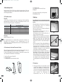
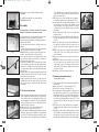
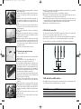
*ELTRAL GU RADIO (D-GB)
3-12-2007
17:55
Pagina 1
Kettenantrieb - Chain drive
ELTRAL KS 30/40 REMOTE
deutsch
english
Montage- und Bedienungsanleitung
Assembly and operating instructions
Gretsch-Unitas GmbH
Baubeschläge
Johann-Maus-Str. 3
D-71254 Ditzingen
www.g-u.de
M-00159-00-0 – 10/2007 – Änderungen vorbehalten / Subject to modification and amendments
*ELTRAL GU RADIO (D-GB)
3-12-2007
17:55
Pagina 2
1 Sicherheitshinweise
Inhalt
1 Sicherheitshinweise
Seite 3
2 Lieferumfang
Seite 5
3 Technische Daten
Seite 5
4 Anwendungsbereich
Seite 6
5 Montage
Seite 7
6 Elektroanschluss
Seite 10
7 LED-Anzeige und DIP-Schalter
Seite 11
8 Funkhandsender
Seite 11
9 Einstellen des Hubes
Seite 12
10 Problembehebung
Seite 13
11 Entsorgung
Seite 13
Contents
1 Safety advice
Page 14
2 Scope of delivery
Page 16
3 Technical data
Page 16
4 Intended use
Page 17
5 Assembly
Page 18
6 Electricalal connection
Page 21
7 LED indication and DIP switches
Page 21
8 Hand-held radio transmitter
Page 22
9 Setting the stroke
Page 23
10 Trouble shooting
11 Disposal
2
Page 23
Page 24
Lesen Sie aufmerksam die folgenden Sicherheitshinweise bevor Sie mit der Montage
des Antriebes beginnen und bewahren Sie dieses Handbuch für ein späteres
Nachschlagen auf.
Anwendungsbereich
• Der Kettenantrieb ELTRAL KS 30/40 ist ausschließlich zum automatischen Öffnen
und Schließen von Kipp-, Klapp-, Dreh-, Schwing-, Wende- und Dachfenstern sowie
von kleinen Dachkuppeln bestimmt.
Der Gebrauch des Antriebes für andere als die genannten Anwendungen muss vom
Hersteller genehmigt werden.
Der Hersteller kann nicht haftbar gemacht werden für Schäden durch nicht bestimmungsgemäßen Gebrauch.
• Bei Kippflügeln müssen zusätzlich immer Sicherheitsscheren oder eine andere geeignete Fangeinrichtung eingebaut werden, die ein eventuelles Herabfallen des Flügels
verhindern. Stellen Sie sicher, dass die Öffnungsweite der Fangeinrichtung für den
Hub des Kettenantriebes ausreichend ist.
• Prüfen Sie immer, ob Ihre Anlage den gültigen Bestimmungen entspricht. Besonders
zu beachten sind Öffnungsweite des Fensters, zulässiges Einbaumaß, Öffnungsgeschwindigkeit, Druckkraft, Querschnitt der Anschlussleitung in Abhängigkeit von
Leitungslänge und Stromaufnahme.
• Benötigtes Befestigungsmaterial ist mit dem Baukörper abzustimmen und wenn
nötig zu ergänzen.
• Der Antrieb ist ausschließlich zur Installation in trockenen Räumen bestimmt.
Schützen Sie den Antrieb dauerhaft vor Schmutz und vor Feuchtigkeit.
D
Montage
• Montage, Installation und Wartung des Antriebes darf nur durch erfahrenes und qualifiziertes Fachpersonal mit Kenntnissen der elektrischen Antriebsmontage durchgeführt werden.
• Nach dem Entfernen der Verpackung ist zu prüfen, ob das Gerät vollständig und
intakt ist.
Plastikbeutel sowie Kleinteile wie Klammern etc. dürfen nicht in Reichweite von
Kindern gelassen werden. Sie stellen potentielle Gefahrenquellen dar.
• Lesen und beachten Sie die Angaben in der Montageanleitung und bewahren Sie
diese für den späteren Gebrauch auf. Ein zuverlässiger Betrieb und ein Vermeiden
von Schäden und Gefahren sind nur bei sorgfältiger Montage und Einstellung nach
der Montageanleitung gegeben.
• Alle Maßangaben sind am Bau eigenverantwortlich zu prüfen und ggf. anzupassen.
Beachten Sie die Anschlussbelegung, die zulässige Antriebsspannung (vgl.
Typenschild), die minimalen und maximalen Leistungsangaben (vgl. technische
Daten) und die Montage- und Installationshinweise und halten Sie diese genau ein.
Leitungsverlegung und elektrischer Anschluss
• Die Leitungsverlegung und der elektrischer Anschluss dürfen nur durch eine zugelassene Elektrofirma ausgeführt werden. Die elektrische Stromversorgung muss
allen geltenden Bestimmungen, Richtlinien und Normen entsprechen.
• Vor der Steuerleitung muss immer ein allpoliger Hauptschalter mit einer
Kontaktöffnung von min. 3 mm installiert werden.
• Vor allen Anschlussarbeiten muss unbedingt die Stromzufuhr zur Steuerung des
Antriebs unterbrochen werden. Verletzungs- oder Lebensgefahr durch Strom!
3
*ELTRAL GU RADIO (D-GB)
3-12-2007
17:55
Pagina 4
Quetsch- und Schergefahr!
• Beim Schließen und Öffnen stoppt der Antrieb über die integrierte Lastabschaltung.
Während des Betriebes übt der Antrieb eine Kraft von ca. 300 N %aus. Dieser Druck
reicht aus, um sich Finger oder andere Körperteile zu quetschen. Bringen Sie
während des Betriebes niemals Hände, andere Körperteile oder Gegenstände zwischen Fensterflügel und Rahmen!
• Flügel müssen bis zu einer Höhe von 2,5 m durch Einrichtungen gesichert sein, die
bei Berührung oder Unterbrechung durch eine Person die Flügelbewegung zum
Stillstand bringen. Auf diese Einrichtungen kann verzichtet werden, wenn der
Gefahrenbereich vom Bedienungsstandort vollständig einzusehen ist und nur beauftragte und unterwiesene Personen die Anlage bedienen können (z.B. mittels
Schlüsseltaster). Die länderspezifischen Richtlinien, wie z.B. Richtlinien für kraftbetätigte Fenster, Türen und Tore (ZH 1/494), sind zu beachten.
Reinigung und Wartung
• Reinigen Sie das Gerät nicht mit lösungsmittelhaltigen Reinigungsmitteln. Tauchen
Sie das Gerät nicht in Wasser ein.
• Die Elektroanlage, der Antrieb und die Beschläge sind mindestens einmal im Jahr auf
ordnungsgemäße Funktion und auf Beschädigungen zu prüfen.
• Reparieren Sie bei einem Defekt den Antrieb nicht selbst. Entfernen Sie weder das
Gehäuse noch andere Teile. Wenden Sie sich bei Schäden am Gerät an den Hersteller.
Es dürfen nur Ersatzteile des Herstellers verwendet werden.
D
2 Lieferumfang
• Kettenantrieb mit Anschlusskabel, Länge 2 m.
• Standard-Schwenklager mit Abstandhalter (A).
• Schwenklager für Klappflügel mit Antriebsmontage in der Laibung (B).
• Kippflügelbock (C).
• Klappflügelbock (D).
• Beutel mit Verschlussbügel und Verbindungsstift Ø4x32.
• Selbstklebende Bohrschablone.
• Montage- und Bedienungsanleitung.
Der zum Bedienen des Kettenantriebes benötigte Funkhandsender KS 30/40 (BestellNr. K-17439-00-0-0) ist nicht im Lieferumfang enthalten und muss gesondert bestellt
werden. Mit einem Handsender können bis zu vier Antriebe angesteuert werden.
3 Technische Daten
MODELL
Schubkraft/Zugkraft
Hub (einstellbar)
Nennspannung
Stromaufnahme bei Nennlast
Leistungsaufnahme bei Nennlast
Schubgeschwindigkeit (Lastunabhängig)
Doppelte elektrische Isolierung
Betriebsart Einschaltdauer
Umgebungstemperatur
Schutzart
Parallelschaltung mehrerer Antriebe
Endabschaltung bei Öffnung
Endabschaltung bei Schließung
Überlastungsschutz bei Öffnung und Schließung
Anschlusskabel
Höhe x Tiefe x Breite
Gewicht
ELTRAL KS 30/40 REMOTE
max. 300 N*
100, 200, 300, 400 mm
230V~ 50Hz
0,12 A
~28 W
10 mm/s
ja
S2 % 3 min
-5 bis +65 ºC
IP30
ja
elektronisch
elektronisch mit Leistungsaufnahme
elektronisch mit Leistungsaufnahme
ca. 2 m
37 x 59 x 386,5 mm
ca. 1,0 kg
D
Die Angaben in dieser Tabelle sind unverbindlich und können auch ohne Vorankündigung geändert werden.
* Kraft-Weg-Diagramm
Nennkraft [N]
300
200
100
Hub [mm]
100 200 300 400
4
5
*ELTRAL GU RADIO (D-GB)
3-12-2007
17:55
Pagina 6
4 Anwendungsbereich
Der Kettenantrieb ELTRAL KS 30/40 ist ausschließlich zum automatischen Öffnen und
Schließen von Kipp-, Klapp-, Dreh-, Schwing-, Wende- und Dachfenstern sowie von kleinen Dachkuppeln bestimmt.
4.1 Flügelabmessungen
Für senkrecht stehende Kipp- oder Klappfenster:
F = (5,4 x P) x (C : H)
5 Montage
Flügelhöhe
Je nach Hub und Anwendung sind die in untenstehender Tabelle aufgeführten
Mindestflügelhöhen einzuhalten. Bei Schwing- und Wendeflügeln beziehen sich die
Werte auf den Abstand Lagerpunkt – Flügelaußenkante.
Hub [mm]
Kippflügel
Mindestflügelhöhe [mm]
Klappflügel
Rahmenmontage
Laibungsmontage
100
200
300
400
250
500
850
1100
150
250
350
450
200
350
600
800
Klappflügel
Flügelbreite
Maximale Flügelbreite: 1500 mm
D
H = Flügelhöhe [mm]
Für Lichtkuppeln oder horizontale Fenster:
F = 5,4 x P
Die Produktinformationen der Systemhersteller, insbesondere Informationen zu
Konstruktion und Verarbeitung, zu max. Flügelabmessungen und max.
Flügelgewichten sowie zu Materialeigenschaften, wie z.B. Längenausdehnungen von
Profilen, sind zu beachten.
4.2 Berechnung der Kraft zum Öffnen bzw. Schließen
Mit den im Folgenden aufgeführten Formeln kann überschlägig ermittelt werden, welche Kraft benötigt wird, um ein Fenster zu Öffnen bzw. zu Schließen.
Es wird von leichtgängigen Fenstern ausgegangen. Gegebenenfalls vorhandene Windoder Schneelasten sind zusätzlich zu berücksichtigen.
F = Kraft zum Öffnen bzw. Schließen [N]
P = Flügelgewicht [kg]
C = Öffnungsweite des Flügels (Antriebshub) [mm]
Abb. 1
Diese Ausführungen richten sich an technisches Fachpersonal. Die
grundlegende Arbeits- und Sicherheitstechnik wird deshalb nicht
behandelt.
Alle Arbeitsschritte der Vorbereitung, der Montage und
des Stromanschlusses müssen von technischem
Fachpersonal ausgeführt werden.
Vorab ist zu prüfen, ob die folgenden grundlegenden
Voraussetzungen erfüllt sind:
• Die Leistungen des Kettenantriebes müssen zur
Bewegung des Fensters ausreichen:
Die Grenzwerte aus den technischen Daten (Kap. 3)
dürfen nicht überschritten werden.
• Achtung: Prüfen Sie, ob die elektrische Versorgung den
Angaben auf dem Typenschild des Antriebes entspricht.
• Stellen Sie sicher, dass der Antrieb keine
Transportschäden erlitten hat. Nach einer optischen
Prüfung ist die Funktion in beiden Hubrichtungen zu
prüfen.
• Stellen Sie anhand der Tabelle der Mindestflügelhöhen
(Kap. 4.1) sicher, dass die Flügelhöhe des Fensters
ausreichend ist für die Montage des Antriebes.
Gegebenenfalls muss vor dem Verbinden von Kette und
Fensterflügel ein geringerer Hub am Kettenantrieb
entsprechend der Tabelle eingestellt werden.
• Bei Kippflügeln muss der Abstand der Innenseiten von
Blendrahmen und Flügel mindestens 1 mm betragen
(Abb. 1) damit ein sicheres Schließen gewährleistet ist.
Bei flächenbündigen Fenstern oder wenn die Innenseite
des Flügels gegenüber dem Blendrahmen zurücksteht,
muss bauseits um den entsprechenden Betrag zwischen Kippflügelkonsole und Flügelprofil unterlegt werden.
Abb. 2
D
Abb. 3
Abb. 4
5.1 Kippfenster
1. Vor Beginn der Arbeiten müssen die Bänder montiert
und der Flügel eingehängt sein. Außerdem ist sicherzustellen, dass mindestens eine Sicherheitsschere
oder eine andere geeignete Fangeinrichtung eingebaut ist, die ein eventuelles Herabfallen des Flügels
sicher
verhindert.
Die
Öffnungsweite
der
Fangeinrichtung
muss
für
den
Hub
des
6
Abb. 5
7
*ELTRAL GU RADIO (D-GB)
Abb. 6
Abb. 7
D
Abb. 8
Abb. 9
3-12-2007
17:55
Pagina 8
Kettenantriebes ausreichend sein.
2. Auf Blendrahmen und Flügel die Mittellinie “X” des
Fensters einzeichnen (Abb. 2).
3. Die geeigneten Konsolen auswählen (Abb. 3).
4. Selbstklebende Bohrschablone an der gestrichelten
roten Linie durchschneiden. Grauen Abschnitt ausgerichtet zur Mittellinie „X“ und bündig zur
Flügeloberkante auf den Fensterflügel kleben. Bei
geschlossenem Flügel den weiß-grauen Abschnitt der
Bohrschablone ebenfalls ausgerichtet zur Mittellinie
„X“ und mit der weißen Seite bündig zur
Flügeloberkante auf den Blendrahmen kleben (Abb.
4).
5. Befestigungslöcher an den auf der Schablone angegebenen Positionen bohren (Schwenklager schwarz,
Kippflügelbock rot) (Abb. 5).
6. Die beiden Schwenklager mit dem Abstandhalter
zusammenstecken (Abb. 3) und mit geeigneten
Schrauben am Blendrahmen montieren. Auf exakte
Ausrichtung achten.
Der Abstandhalter dient nur zur korrekten
Positionierung. Er kann anschließend wieder entfernt
werden.
7. Kippflügelbock mit geeigneten Schrauben am Flügel
montieren.
8. Verbinden Sie den Verschlussbügel mit dem
Kettenende indem Sie den Verbindungsstift Ø4x32
durch beide Teile stecken (Abb. 6).
9. Kettenantrieb auf die Schwenklager montieren: Dazu
den Antrieb (Kettenaustritt nach unten zeigend) von
vorne mit seinen Aussparungen an den Enden auf die
Lagerzapfen der Schwenklager stecken. Den Antrieb
um 90° schwenken.
10.Prüfen Sie, ob der Kettenaustritt genau auf einer Linie
mit dem Kippflügelbock liegt. Andernfalls die
Befestigungsschrauben lösen und die Konsolen korrekt neu positionieren.
11. Stromanschluss wie in Kap. 6 beschrieben vornehmen.
12.Kette so weit ausfahren, dass der Verbindungsstift am
Kettenende in das Langloch des Kippflügelbocks eingeführt werden kann. Den Verschlussbügel durch kräftigen Druck am Kippflügelbock hörbar einrasten lassen. Korrekte Verbindung prüfen.
13.Korrekte Funktion durch einen Probelauf überprüfen.
5.2 Klappfenster (Antrieb montiert am Blendrahmen)
Abb. 10
8
1. Vor Beginn der Arbeiten müssen die Bänder montiert
und der Flügel eingehängt sein.
2. Auf Blendrahmen und Flügel die Mittellinie “X” des
Fensters einzeichnen (Abb. 7).
3. Die geeigneten Konsolen auswählen (Abb. 8).
4. Selbstklebende Bohrschablone an der gestrichelten
grünen Linie durchschneiden. Grauen Abschnitt bei
geschlossenem Flügel ausgerichtet zur Mittellinie „X“
und bündig zur Blendrahmenkante auf den
Fensterflügel kleben. Den weiß-grauen Abschnitt der
Bohrschablone ebenfalls ausgerichtet zur Mittellinie „X“
und mit der weißen Seite bündig zur Rahmenoberkante
auf den Blendrahmen kleben (Abb. 9).
5. Befestigungslöcher an den auf der Schablone angegebenen Positionen bohren (Schwenklager schwarz,
Klappflügelbock grün) (Abb. 10).
6. Die beiden Schwenklager mit dem Abstandhalter
zusammenstecken (Abb. 8) und mit geeigneten
Schrauben am Blendrahmen montieren. Auf exakte
Ausrichtung achten.
Der Abstandhalter dient nur zur korrekten
Positionierung. Er kann anschließend wieder entfernt
werden.
7. Klappflügelbock mit geeigneten Schrauben am Flügel
montieren.
8. Verbinden Sie den Verschlussbügel mit dem
Kettenende indem Sie den Verbindungsstift Ø4x32
durch beide Teile stecken (Abb. 11).
9. Kettenantrieb auf die Schwenklager montieren: Dazu
den Antrieb (Kettenaustritt nach unten zeigend) von
vorne mit seinen Aussparungen an den Enden auf die
Lagerzapfen der Schwenklager stecken. Den Antrieb
um 90° schwenken.
10.Prüfen Sie, ob der Kettenaustritt genau auf einer Linie
mit dem Klappflügelbock liegt. Andernfalls die
Befestigungsschrauben lösen und die Konsolen korrekt neu positionieren.
11. Stromanschluss wie in Kap. 6 beschrieben vornehmen.
12.Falls aufgrund der Einbausituation erforderlich (z.B.
geringe Flügelhöhe) einen kürzeren Kettenhub am
Antrieb programmieren (Kap. 8).
13.Kette so weit ausfahren, dass der Verbindungsstift am
Kettenende in das Langloch des Klappflügelbocks eingeführt werden kann. Den Verschlussbügel durch kräftigen Druck am Klappflügelbock hörbar einrasten lassen. Korrekte Verbindung prüfen.
14.Korrekte Funktion durch einen Probelauf überprüfen.
Abb. 11
Abb. 12
D
Abb. 13
Abb. 14
5.3 Klappfenster (Antrieb montiert in der Laibung)
1. Vor Beginn der Arbeiten müssen die Bänder montiert
und der Flügel eingehängt sein.
2. Auf Blendrahmen und Flügel die Mittellinie “X” des
Fensters einzeichnen (Abb. 12).
3. Die geeigneten Konsolen auswählen (Abb. 13).
4. Selbstklebende Bohrschablone an der gestrichelten
grünen Linie durchschneiden. Grauen Abschnitt bei
geschlossenem Flügel ausgerichtet zur Mittellinie „X“
und bündig zur Blendrahmenkante auf den
Abb. 15
9
*ELTRAL GU RADIO (D-GB)
3-12-2007
17:55
Pagina 10
Fensterflügel kleben. Den weiß-grauen Abschnitt der Bohrschablone ebenfalls
ausgerichtet zur Mittellinie „X“ und mit der weißen Seite bündig zum Flügelprofil
auf den Blendrahmen kleben.
Bei besonderen Montagesituationen kann es nötig sein, die korrekte Position der
Konsolen durch Auflegen der Teile am Fenster zu ermitteln.
5. Befestigungslöcher an den markierten Positionen bohren (auf Schablone:
Schwenklager blau, Klappflügelbock grün) (Abb. 14).
6. Klappflügelbock mit geeigneten Schrauben am Flügel montieren. Auf exakte
Ausrichtung achten.
7. Verbinden Sie den Verschlussbügel mit dem Kettenende indem Sie den
Verbindungsstift Ø4x32 durch beide Teile stecken (Abb. 15).
8. Die beiden Schwenklager in die Vertiefungen an den Seiten des Antriebes stecken.
9. Den Antrieb auf den zuvor gebohrten Löchern positionieren und mit geeigneten
Schrauben befestigen.
10.Prüfen Sie, ob der Kettenaustritt genau auf einer Linie mit dem Klappflügelbock
liegt. Andernfalls die Befestigungsschrauben lösen und die Konsolen korrekt neu
positionieren.
11. Stromanschluss wie in Kap. 6 beschrieben vornehmen.
12.Falls aufgrund der Einbausituation erforderlich (z.B. geringe Flügelhöhe) einen kürzeren Kettenhub am Antrieb programmieren (Kap. 8).
13.Kette so weit ausfahren, dass der Verbindungsstift am Kettenende in das Langloch
des Klappflügelbocks eingeführt werden kann. Den Verschlussbügel durch kräftigen
Druck am Klappflügelbock hörbar einrasten lassen. Korrekte Verbindung prüfen.
14.Korrekte Funktion durch einen Probelauf überprüfen.
D
6 Elektroanschluss
Der Kettenantrieb ELTRAL KS 30/40 REMOTE besitzt ein ca. 2 m langes zweiadriges
Anschlusskabel. Es muss an eine Netzspannung von 230 V ~ 50 Hz angeschlossen
werden.
Die Steuerbefehle ÖFFNEN und SCHLIESSEN werden mit dem Funkhandsender KS
30/40 (Bestell-Nr. K-17439-00-0-0) erteilt. Die Steuerung über einen fest verdrahteten
Schalter oder Taster ist nicht möglich.
Der Anschluss des Antriebes ist nach dem folgenden Schaltbild vorzunehmen.
7 LED-Anzeige und DIP-schalter
LED-Anzeige und DIP-Schalter sitzen vertieft auf der Seite gegenüber dem Ausgang
des Anschlusskabels. Die LED-Anzeige zeigt die verschiedenen Betriebszustände des
Antriebes an.
Status der LED
Bedeutung
Ständig leuchtend
Kurzes Aufblitzen
Antrieb in Betrieb.
Antrieb hat den Endschalter in Offenstellung
erreicht.
Antrieb durch die elektronische Lastabschaltung
gestoppt.
Antrieb ist in einer anormalen Position.
Er hat die Programmierung verloren.
Gleichmäßiges Blinken
Leuchtend mit Dunkelblitz
Mit den DIP-Schaltern erfolgt die Programmierung der Funkhandsender (DIP-Schalter
1) (Kap. 8) und die Einstellung des Kettenhubes (DIP-Schalter 3 und 4) (Kap. 9.2). DIPSchalter 2 ist ohne Funktion.
8 Funkhandsender
Der Kettenantrieb ELTRAL KS 30/40 REMOTE wird ausschließlich mit dem
Funkhandsender KS 30/40 (Bestell-Nr. K-17439-00-0-0) bedient. Dieser Handsender
besitzt 4 Tasten mit denen 4 Antriebe unabhängig voneinander gesteuert werden können. Andererseits können jedem Antrieb bis zu 8 Handsender zugeordnet werden. Ein
neunter Sender wird nicht mehr übernommen.
D
Die Funkübertragung arbeitet mit einer Übertragungsfrequenz von 433,92 MHz und
mit einem variablen Code (“Rollcode“) mit 16 Milliarden Kombinationsmöglichkeiten.
Der Code ändert sich bei jedem Übertragungsvorgang nach einem Algorithmus, der
den verwendeten Code verdeckt, so dass ein optimales Maß an Sicherheit gewährleistet ist.
Der Handsender ist bereits werkseitig mit einer Batterie ausgestattet und daher sofort
funktionsfähig.
Zum Batteriewechsel den Handsender durch Herausdrehen der beiden Schrauben auf
seiner Rückseite öffnen. Batterie entnehmen und durch eine neue Batterie gleichen
Typs (Typ 23A, 12 V) ersetzen. Die Programmierung des Senders bleibt dabei erhalten.
Die entnommene Batterie ist gemäß den gesetzlichen Bestimmungen der
Wiederverwertung zuzuführen.
Speichern eines Funkhandsenders
N
F
10
230V~ 50Hz
ACHTUNG: Dieselbe Taste eines Handsenders kann nicht mehreren Antrieben zugeordnet werden.
1. DIP-Schalter 1 in Stellung ON umlegen, sodass die rote LED aufleuchtet.
Anschließend den DIP-Schalter sofort wieder auf OFF zurück stellen.
2. Die Taste auf dem Handsender, die dem Antrieb zugewiesen werden soll, solange
betätigen, bis die LED am Antrieb aufblinkt.
3. Sobald die LED am Antrieb zu blinken aufhört, ist die Programmierung abgeschlossen.
11
*ELTRAL GU RADIO (D-GB)
3-12-2007
17:55
Pagina 12
Speichern eines weiteren Handsenders wenn
die DIP-Schalter NICHT zugänglich sind
1. Gleichzeitig etwa eine Sekunde lang die Tasten
1, 2, 4 auf dem bereits eingespeicherten
Handsender drücken, dann die Taste betätigen, mit dem der Antrieb bedient wird.
2. Die rote LED des Antriebes leuchtet auf.
3. Die Taste des neuen Handsenders drücken, die
dem Antrieb zugewiesen werden soll. Die LED
des Antriebes beginnt zu blinken, sobald die
Taste des Handsenders losgelassen wird.
4. Sobald die LED am Antrieb zu blinken aufhört,
ist die Programmierung abgeschlossen.
10 Problembehebung
2
1
3
Mögliche Ursache
In Schließstellung schaltet der Antrieb über die integrierte Lastabschaltung ab. Es
müssen daher keine Endschalter eingestellt werden. Nach Erreichen der Endlage führt
der Antrieb einen Rückhub von ca. 1 mm aus. Dadurch werden sowohl die Dichtungen
als auch die Befestigungskonsolen entlastet.
Der Antrieb funktioniert nicht.
• Das Netzteil wird nicht mit elek- • Zustand des Fehlerstromtrischer Energie gespeist.
Schutzschalters oder des
Sicherheitsschalters prüfen.
• Anschlusskabel nicht ange- • Alle Stromanschlüsse des
schlossen oder ein Draht lose.
Antriebes kontrollieren.
• Das Schaltnetzteil im Antrieb • Antrieb austauschen.
ist defekt und stellt keine
Niederspannung bereit.
Trotz der korrekten Einstellung • Die Programmierung wurde • DIP-Schalter neu programmiefindet der Antrieb keinen nicht korrekt ausgeführt.
ren.
Endschalter.
• Störung oder Unterbrechung • Antrieb austauschen.
des elektrischen DIP-SchalterKontaktes.
Der Antrieb läuft nicht an.
9.2 Einstellen des Hubes
Werkseitig ist der Hub des Kettenantriebes auf 400 mm eingestellt. Mit den DIPSchaltern 3 und 4 kann der Hub jederzeit umgestellt werden. Es müssen lediglich die
DIP-Schalter entsprechend der folgenden Tabelle umgelegt werden. Damit die Änderung wirksam wird, muss die Kette ein kleines Stück ausgefahren und anschließend
wieder eingefahren werden.
Abschließend sollte ein Probelauf durchgeführt werden.
Hub (mm)
100
200
300
400
Abhilfe
Die LED leuchtet auf, aber der • Der Antrieb wurde durch Über- • Antrieb austauschen.
Antrieb funktioniert nicht.
spannung beschädigt oder hat
einen anderen Defekt.
9.1 Abschaltung in Schließstellung
12
Problem
4
9 Einstellen des Hubes
D
Treten bei der Installation oder im normalen Betrieb des Antriebes Probleme auf, kann
mit Hilfe der folgenden Tabelle Abhilfe geschaffen werden.
• Der Funkhandsender ist vom • Die
Abspeicherung
des
Empfänger nicht übernommen Funkhandsenders wiederholen.
worden.
D
11 Entsorgung
Der Antrieb enthält elektrische Teile und muss entsprechend den gesetzlichen
Bestimmungen entsorgt werden.
DIP-Schalter
3
OFF
ON
OFF
ON
4
OFF
OFF
ON
ON
13
*ELTRAL GU RADIO (D-GB)
3-12-2007
17:55
Pagina 14
1 Safety advice
Please read the following safety indications carefully before mounting the drive and
keep this manual for future consultation.
Intended use
• The chain drive ELTRAL KS 30/40 is designed exclusively for the automatic opening
and closing of tilt windows, top hung outward opening windows, side hung windows,
horizontal and vertical pivot windows, roof lights and small domes.
Any use of the drive for applications other than those indicated must be authorised by
the manufacturer who cannot be held liable for damage arising from improper use.
• In the case of bottom hung tilt sashes, it is necessary to always install additional
security stays or another suitable catching device preventing the sash from accidental fall. Ensure that the opening distance of the catching device is sufficiently large
to match the stroke of the drive.
• Always verify if your appliance complies with the prevailing regulations. Special
attention must be paid to : opening distance of window, allowed installation dimensions, opening speed, compressive force, cross section of connecting cable depending on cable length and current consumption.
• Fixing material must be compatible with the structure and supplemented if required.
• The drive is designed for the use in dry rooms only. Ensure that it is permanently protected against moisture and dirt.
GB
Assembly
• The appliance must only be assembled and serviced by experienced and qualified
technical staff competent in the installation of electrical drives.
• After removing all packaging, please verify that all parts of the appliance are present
and intact.
Plastic bags and small parts such as clips etc. must be kept out of the reach of children as they are potential sources of danger.
• Read and observe all details of the assembly instructions which are to be kept for
future consultation. Reliable functioning and prevention of risk and damage are only
achieved with accurate assembly and setting according to the instructions.
• All dimensions of the particular location are the responsibility of the installer. Ensure
that the terminal assignment is correct. Observe the allowed drive voltage (see type
label) and the minimum and maximum ratings (see technical data). Carefully adhere
to all assembly details given.
with devices stopping the sash movement as soon as they are touched by a person.
However, if the dangerous zone can be completely overlooked from the operating
station and if the installation is operated by authorised and trained persons only (e.g.
via key switch), such safety devices are not required. Country specific regulations are
to be observed.
Cleaning and maintenance
• Do not clean the appliance with solvent cleaning agents.
Do not immerse the appliance in water.
• Electrical system, drive and fittings must be checked for proper functioning and for
damage at least once a year.
• Do not try to repair the drive yourself in case of failure. Do not remove the casing nor
other parts. In case of signs of damage to the appliance contact the manufacturer.
Only spare parts supplied by the manufacturer may be used for repair.
GB
Cable routeing and electrical connection
• Cable routeing and electrical connection must only be carried out by approved electricians. The current supply must be in accordance with all prevailing regulations,
directives and standards.
• An all-pole circuit breaker with a minimum contact opening of 3 mm must always be
installed before the control line.
• Any connecting work must be carried out with the drive control cut off from the
mains. There is risk of injury and even danger of life as a result of electrical shock !
Risk of crushing!
• The opening and closing action is stopped by the integral load interruption. During
function the drive applies a pressure force of approx. 300 N which is enough to crush
fingers or other parts of the body. Never get your hands or other parts of your body,
nor any objects between sash and frame as the drive is operating !
• Unless installed higher than 2,5 m above floor level, sashes must be safeguarded
14
15
*ELTRAL GU RADIO (D-GB)
3-12-2007
17:55
Pagina 16
2 Scope of delivery
4 Intended use
• Chain drive with connecting cable, length 2 m
• Standard bracket with distancer (A)
• Bracket for soffit mounting of top hung sashes opening outward (B)
• Chain holder for tilt sash (C)
• Chain holder for top hung opening outward sash (D)
• Package with locking piece and connecting pin Ø4x32
• Self-adhesive drilling template
• Assembly and operating instructions
The chain drive ELTRAL KS 30/40 is designed exclusively for the automatic opening
and closing of tilt windows, top hung outward opening windows, side hung windows,
horizontal and vertical pivot windows, roof lights and small domes.
The hand-held radio transmitter KS 30/40 (order no. K-17439-00-0-0) required for the
operation of the chain drive is not included in the delivery and must be ordered separately. The hand-held radio transmitter controls up to four drives.
3 Technical data
GB
TYPE
Push/Pull force
Stroke (adjustable)
Nominal voltage
Current consumption at nominal load
Power input at nominal load
Stroke speed (load independent)
Double electricalal insulation
Duty (power-on time)
Ambient temperature
Protection class
Connection of several drives in parallel
Limit switch stop at opening
Limit switch stop at closing
Overload protection at opening and closing
Connecting cable
Height x Depth x Width
Weight
ELTRAL KS 30/40 REMOTE
max. 300 N *
100, 200, 300, 400 mm
230 V ~ 50 Hz
0,12 A
~ 28 W
10 mm/s
yes
S2 3 min
- 5 to + 65 ºC
IP 30
yes
electronic
electronic with power input
electronic with power input
approx. 2 m
37 x 59 x 386,5 mm
approx. 1,0 kg
4.1 Sash dimensions
Sash height
Depending on the stroke and the respective application, the minimum sash heights
specified below are to be observed. For horizontal or vertical pivot windows the values
refer to the distance between pivot and outside edge of sash.
Stroke [mm]
Tilt sash
100
200
300
400
250
500
850
1100
Mindestflügelhöhe [mm]
Outward opening
Outward opening
frame-mounted
soffit-mounted
150
250
350
450
200
350
600
800
Sash width
Maximum sash width: 1500 mm
The product guidelines of the profile manufacturers regarding construction, assembly,
max. sash dimensions, max. sash weights and material qualities (e.g. longitudinal
expansion) are to be observed.
GB
4.2 Calculating the opening/closing force
With the formulae indicated below it is possible to determine the approximate force
required to open or close a (smooth-running) window; possible wind or snow loads are
to be considered.
The specifications stated in this table are not binding and may be changed without notice.
* Load-displacement diagram
Nennkraft [N]
300
200
100
Hub [mm]
F = Opening/closing force
P = Sash weight
C = Opening distance of sash (stroke)
H = Height of sash
[N]
[kg]
[mm]
[mm]
100 200 300 400
17
*ELTRAL GU RADIO (D-GB)
3-12-2007
17:55
Pagina 18
For light domes or horizontally installed windows:
F = 5,4 x P
For vertically installed tilt or top hung windows:
F = (5,4 x P) x (C : H)
5 Assembly
Fig. 1
Fig. 2
GB
Fig. 3
The following details are intended for the attention of specialised
staff. Basic job safety details are therefore not included.
Any preparatory work, assembly and electricalal connections must be carried out by trained technicians.
First of all, please verify that the following technical preconditions are fulfilled:
• The chain drive’s power must be sufficient to move the
window.
The limit values indicated in the technical specification
table (see chapter 3) must not be exceeded.
• Attention: Please check if the electricalal supply corresponds to the specifications on the type label.
• Ensure that the drive was not damaged during transport. After the visual check, verify the correct functioning in both stroke directions.
• Verify that the window sash is sufficiently high to allow
for the assembly of the drive (see table minimum sash
heights in 4.1). It might be necessary to adjust the drive
to a smaller stroke before connecting the window sash
with the chain.
• With tilt sashes, the clearance between frame and sash
profile must be at least 1 mm (Fig. 1) in order to provide
for safe closing of the window.
If frame and sash profiles are flush, or if the sash profile stands back from the frame profile on the interior
side, it is necessary to underlay the tilt sash bracket
accordingly.
5.1 Tilt window (bottom hung)
Fig. 4
Fig. 5
18
1. Before assembly, the hinges must be mounted and the
sash hinged. Ensure that at least one security stay or
other catching device are installed to reliably secure
the sash against accidental fall. The opening distance
of the catching device must be sufficiently large to
match the stroke of the drive.
2. Mark centre line “X” on sash and frame (Fig. 2).
3. Select the correct type of bracket (Fig. 3).
4. Cut self-adhesive drilling template at dashed red line.
Attach the grey part to the window sash aligned with
centre line “X“ and flush with the top edge of the sash.
Then, with the sash closed, attach the grey-white part
of the template to the frame, also aligned with the
centre line “X” and the white side flush with the top
edge of the sash (Fig. 4).
5. Drill holes at the points indicated on the template –
bracket black, chain holder for tilt sash red (Fig. 5).
6. Assemble the two brackets with the distancer (Fig. 3)
and fix them on the frame with suitable screws.
Ensure that they are correctly positioned. Serving as
positioning aid only, the distancer may be removed
afterwards.
7. Fasten chain holder for tilt sash (C) to the frame with
suitable screws.
8. Connect the locking piece with the chain end by inserting the connecting pin Ø4x32 through both parts.
(Fig. 6).
9. Mount the drive (chain end directed downwards) on
the brackets by slipping it onto the journals of the
brackets by its lateral notches. Rotate the drive by
90°.
10.Verify if the chain end is perfectly aligned with the
chain holder. If not, loosen fixing screws and reposition the brackets.
11. Carry out the electricalal connection as described in
chapter 6.
12.Extend the chain as far as to allow for the connecting
pin on the chain end to be inserted in the slot of the
chain holder. Press the locking piece firmly onto the
chain holder until it snaps in audibly. Ensure that the
connection is tight.
13.Verify the correct functioning in a test run.
Fig. 6
Fig. 7
GB
Fig. 8
5.2 Outward opening window (top hung)
Drive mounted to frame
1. Before assembly, the hinges must be mounted and the
sash hinged.
2. Mark centre line “X” on sash and frame (Fig. 7).
3. Select the correct type of bracket (Fig. 8).
4. Cut self-adhesive drilling template at dashed green
line. Attach the grey part to the closed window sash
aligned with centre line “X“ and flush with edge of the
frame. Attach the grey-white part of the template to
the frame, also aligned with the centre line “X” and
the white side flush with the top edge of the frame
(Fig. 9).
5. Drill holes at the points indicated on the template –
bracket black, chain holder for top hung sash green
(Fig. 10).
6. Assemble the two brackets with the distancer (Fig. 8)
and fix them on the frame with suitable screws. Ensure
that they are correctly positioned. Serving as positioning aid only, the distancer may be removed afterwards.
Fig. 9
Fig. 10
19
*ELTRAL GU RADIO (D-GB)
Fig. 11
Fig. 12
3-12-2007
17:55
Pagina 20
7. Fasten chain holder for top hung sash (D) to the frame
with suitable screws.
8. Connect the locking piece with the chain end by inserting the connecting pin Ø4x32 through both parts.
(Fig. 11).
9. Mount the drive (chain end directed downwards) on
the brackets by slipping it onto the journals of the
brackets by its lateral notches. Rotate the drive by
90°.
10.Verify if the chain end is perfectly aligned with the
chain holder. If not, loosen fixing screws and reposition the brackets.
11. Carry out the electricalal connection as described in
chapter 6.
12.Depending on the particular situation (e.g. small sash
height), it might be necessary to programme a shorter
chain stroke (see chapter 8).
13.Extend the chain as far as to allow for the connecting
pin on the chain end to be inserted in the slot of the
chain holder. Press the locking piece firmly onto the
chain holder until it snaps in audibly. Ensure that the
connection is tight.
14.Verify the correct functioning in a test run.
10.Verify if the chain end is perfectly aligned with the chain holder. If not, loosen fixing
screws and reposition the brackets.
11. Carry out the electricalal connection as described in chapter 6.
12.Depending on the particular situation (e.g. small sash height), it might be necessary to programme a shorter chain stroke (see chapter 8).
13.Extend the chain as far as to allow for the connecting pin on the chain end to be
inserted in the slot of the chain holder. Press the locking piece firmly onto the chain
holder until it snaps in audibly. Ensure that the connection is tight.
14.Verify the correct funtioning in a test run.
6 Electricalal connection
The chain drive ELTRAL KS 30/40 REMOTE comes with a 2 mtr two-core supply cable
which is to be connected to a mains voltage of 230 V ~ 50 Hz.
The commands OPEN and CLOSE are given with the hand-held radio transmitter KS
30/40 (order no. K-17439-00-0-0). Control via hard-wired switch is not possible.
The connection is to be carried out according to the following wiring diagrams.
5.3 Outward opening window (top hung)
Drive mounted to soffit
GB
Fig. 13
Fig. 14
1. Before assembly, the hinges must be mounted and the
sash hinged.
2. Mark centre line “X” on sash and frame (Fig. 12).
3. Select the correct type of bracket (Fig. 13).
4. Cut self-adhesive drilling template at dashed green
line. Attach the grey part to the closed window sash
aligned with centre line “X“ and flush with edge of the
frame. Attach the grey-white part of the template to
the frame, also aligned with the centre line “X” and
the white side flush with the sash profile.
In some cases, it might be necessary to place the parts
themselves on the window in order to determine the
correct position of the brackets.
5. Drill holes at the points indicated on the template –
bracket blue, chain holder for top hung sash green
(Fig. 14).
6. Fasten chain holder for top hung sash (D) to the frame
with suitable screws, ensuring that it is correctly aligned.
7. Connect the locking piece with the chain end by inserting the connecting pin Ø4x32 through both parts.
(Fig. 15).
8. Plug the two brackets into the the recesses on each
side of the drive.
9. Place the drive on the holes drilled before and fasten
with suitable screws.
GB
N
F
230V~ 50Hz
7 LED indication and DIP switches
LED and DIP switches are located on the opposite side of the connecting cable outlet.
The LED indicates the drive’s different modes of operation.
Status of LED
Meaning
Constantly lit
Off and flashing
Regular blinking
On and flashing
Drive in operation.
Drive has reached the limit stop in open position.
Drive is stopped by the electronic load interruption.
Drive is in abnormal position; programming lost.
Fig. 15
20
21
*ELTRAL GU RADIO (D-GB)
3-12-2007
17:55
Pagina 22
The hand-held radio transmitter is programmed with DIP switch 1 (see chapter 8), the
stroke of the chain is set with DIP switches 3 and 4 (see chapter 9.2). DIP switch 2 is
without function.
8 Hand-held radio transmitter
The chain drive ELTRAL KS 30/40 REMOTE is controlled exclusively with the hand-held
radio transmitter KS 30/40 (order no. K-17439-00-0-0). This transmitter is provided
with 4 buttons controlling 4 drives independently from each other. Vice versa, up to 8
transmitters may be allocated to each drive. A ninth sender is not accepted.
The radio transmitter operates at a frequency of 433,92 MHz and with a variable code
(“rollcode”) allowing for 16 billion combinations. At each transmission, the code changes
according to an algorithm hiding the code used, thus guaranteeing utmost security.
9 Setting the stroke
9.1 Switch-off in closed position
Thanks to the integral load interruption, the drive switches off in closed position.
Setting the limit switch is therefore not required. When the end position is reached,
the drive carries out a reverse stroke of approx. 1 mm. thus relieving both gaskets and
holding brackets.
9.2 Setting the stroke
The factory setting of the stroke is 400 mm; it can be changed via DIP switches 3 and
4 at any time according to the settings of the following table. In order to make a change effective, it is necessary to extend the chain a little bit and retract it again.
After changing the stroke, a test run should be carried out.
Delivered with a battery, the hand-held transmitter is serviceable from the start. For a
battery change open the transmitter by removing the two screws on the back. Replace
the old battery by a new one of the same type (23 A, 12 V). During battery change, the
transmitter’s programming is stored. Dispose the used battery according to the prevailing legal recycling regulations.
Stroke (mm)
100
200
300
400
Storing a hand-held radio transmitter
GB
ATTENTION: One and the same button of a hand-held transmitter cannot be allocated
to several drives.
1. Set DIP switch 1 to position ON, the red LED will light up. Immediately hereafter set
the DIP switch to position OFF again.
2. Press the button on the transmitter which you want to allocate to the drive until the
LED on the drive flashes.
3. As soon as the LED on the drive stops flashing, the programming is terminated.
22
1
3
2
4
OFF
OFF
ON
ON
10 Trouble shooting
GB
In case any problems arise during installation or operation of the drive, please consult the following table for possible help:
Problem
Possible cause
Drive not functioning.
• Mains adapter without current • Check state of fault current prosupply.
tection switch or safety switch.
• Connecting cable unplugged or • Check all electricalal connecwire(s) loose.
tions of drive.
• Switching mains adapter in the • Exchange mains adapter.
drive damaged, not providing
low voltage.
LED lit but drive not working.
• Drive damaged as a result of • Exchange drive.
overvoltage or other destruction.
Limit switch not functioning.
• Programming not carried out • Repeat programming of DIP
correctly.
switch.
• Failure of the electrical DIP • Exchange drive.
switch contact.
Drive not starting.
• Hand-held radio transmitter not • Repeat storage of hand-held
accepted by the receiver.
transmitter.
Storing a further hand-held transmitter with
the DIP switches NOT being accessible
1. Press buttons 1, 2, 4 of the hand-held transmitter already stored for about one second, then
press the button with which the drive is operated.
2. The LED of the drive will light up.
3. Press the button on the new hand-held transmitter to be allocated to the drive. The LED
on the drive will start flashing as soon as the
button on the transmitter is released.
4. As soon as the LED on the drive stops flashing, the programming is terminated.
DIP switch
3
OFF
ON
OFF
ON
4
Solution
23
*ELTRAL GU RADIO (D-GB)
3-12-2007
17:55
Pagina 24
11 Disposal
The drive contains electricalal parts and must be disposed of according to prevailing
legal regulations.
GB
GB
24
25
*ELTRAL GU RADIO (D-GB)
3-12-2007
17:55
Pagina 26
GB
GB
26
27