1
H 2500 | H 5000
PowerH SERIES Amplifier
Owner‘s Manual | Bedienungsanleitung | Mode d‘emploi
PowerH SERIES
CONTENTS
Introduction . . . . . . . . . . . . . . . . . . . . . . . . . . . . . . . . . . . . . . . . . . . . . . . . . . . . . . . . . . . . . . . . .
Welcome . . . . . . . . . . . . . . . . . . . . . . . . . . . . . . . . . . . . . . . . . . . . . . . . . . . . . . . . . . . . . .
Unpacking and Inspection . . . . . . . . . . . . . . . . . . . . . . . . . . . . . . . . . . . . . . . . . . . . . . . . .
Scope of Delivery and Warranty . . . . . . . . . . . . . . . . . . . . . . . . . . . . . . . . . . . . . . . . . . . . .
Features and Description . . . . . . . . . . . . . . . . . . . . . . . . . . . . . . . . . . . . . . . . . . . . . . . . . .
Responsibility of the User . . . . . . . . . . . . . . . . . . . . . . . . . . . . . . . . . . . . . . . . . . . . . . . . . .
Installation . . . . . . . . . . . . . . . . . . . . . . . . . . . . . . . . . . . . . . . . . . . . . . . . . . . . . . . . . . . . . . . . . .
Controls, Indicators and Connections . . . . . . . . . . . . . . . . . . . . . . . . . . . . . . . . . . . . . . . .
Operating Voltage . . . . . . . . . . . . . . . . . . . . . . . . . . . . . . . . . . . . . . . . . . . . . . . . . . . . . . .
Mains Switch . . . . . . . . . . . . . . . . . . . . . . . . . . . . . . . . . . . . . . . . . . . . . . . . . . . . . . . . . . .
Mounting . . . . . . . . . . . . . . . . . . . . . . . . . . . . . . . . . . . . . . . . . . . . . . . . . . . . . . . . . . . . . . .
Ventilation . . . . . . . . . . . . . . . . . . . . . . . . . . . . . . . . . . . . . . . . . . . . . . . . . . . . . . . . . . . . . .
Groundlift . . . . . . . . . . . . . . . . . . . . . . . . . . . . . . . . . . . . . . . . . . . . . . . . . . . . . . . . . . . . . .
Indication of the Operation Mode . . . . . . . . . . . . . . . . . . . . . . . . . . . . . . . . . . . . . . . . . . . .
Selecting the Mode Of Operation . . . . . . . . . . . . . . . . . . . . . . . . . . . . . . . . . . . . . . . . . . . .
Operation . . . . . . . . . . . . . . . . . . . . . . . . . . . . . . . . . . . . . . . . . . . . . . . . . . . . . . . . . . . . . . . . . . .
Volume Control . . . . . . . . . . . . . . . . . . . . . . . . . . . . . . . . . . . . . . . . . . . . . . . . . . . . . . . . . .
Graphical LC display . . . . . . . . . . . . . . . . . . . . . . . . . . . . . . . . . . . . . . . . . . . . . . . . . . . . .
Indications . . . . . . . . . . . . . . . . . . . . . . . . . . . . . . . . . . . . . . . . . . . . . . . . . . . . . . . . . . . . .
Fan Cooling . . . . . . . . . . . . . . . . . . . . . . . . . . . . . . . . . . . . . . . . . . . . . . . . . . . . . . . . . . . .
Protections . . . . . . . . . . . . . . . . . . . . . . . . . . . . . . . . . . . . . . . . . . . . . . . . . . . . . . . . . . . . .
Options . . . . . . . . . . . . . . . . . . . . . . . . . . . . . . . . . . . . . . . . . . . . . . . . . . . . . . . . . . . . . . . . . . . .
RCM-26 . . . . . . . . . . . . . . . . . . . . . . . . . . . . . . . . . . . . . . . . . . . . . . . . . . . . . . . . . . . . . . .
5
5
5
5
6
6
7
7
9
11
12
13
13
14
14
19
19
19
30
31
31
35
35
INHALTSVERZEICHNIS
Einführung . . . . . . . . . . . . . . . . . . . . . . . . . . . . . . . . . . . . . . . . . . . . . . . . . . . . . . . . . . . . . . . . .
Willkommen . . . . . . . . . . . . . . . . . . . . . . . . . . . . . . . . . . . . . . . . . . . . . . . . . . . . . . . . . . . .
Auspacken und Inspektion . . . . . . . . . . . . . . . . . . . . . . . . . . . . . . . . . . . . . . . . . . . . . . . . .
Lieferumfang und Garantie . . . . . . . . . . . . . . . . . . . . . . . . . . . . . . . . . . . . . . . . . . . . . . . . .
Eigenschaften & Beschreibung . . . . . . . . . . . . . . . . . . . . . . . . . . . . . . . . . . . . . . . . . . . . .
Verantwortung des Betreibers . . . . . . . . . . . . . . . . . . . . . . . . . . . . . . . . . . . . . . . . . . . . . .
Installation . . . . . . . . . . . . . . . . . . . . . . . . . . . . . . . . . . . . . . . . . . . . . . . . . . . . . . . . . . . . . . . . . .
Bedienelemente, Anzeigen und Anschlüsse . . . . . . . . . . . . . . . . . . . . . . . . . . . . . . . . . . .
Betriebsspannung . . . . . . . . . . . . . . . . . . . . . . . . . . . . . . . . . . . . . . . . . . . . . . . . . . . . . . .
Netzschalter . . . . . . . . . . . . . . . . . . . . . . . . . . . . . . . . . . . . . . . . . . . . . . . . . . . . . . . . . . . .
Einbau . . . . . . . . . . . . . . . . . . . . . . . . . . . . . . . . . . . . . . . . . . . . . . . . . . . . . . . . . . . . . . . .
Kühlung . . . . . . . . . . . . . . . . . . . . . . . . . . . . . . . . . . . . . . . . . . . . . . . . . . . . . . . . . . . . . . .
Groundlift . . . . . . . . . . . . . . . . . . . . . . . . . . . . . . . . . . . . . . . . . . . . . . . . . . . . . . . . . . . . . .
Anzeige der Betriebsart . . . . . . . . . . . . . . . . . . . . . . . . . . . . . . . . . . . . . . . . . . . . . . . . . . .
Wahl der Betriebsart . . . . . . . . . . . . . . . . . . . . . . . . . . . . . . . . . . . . . . . . . . . . . . . . . . . . . .
Betrieb . . . . . . . . . . . . . . . . . . . . . . . . . . . . . . . . . . . . . . . . . . . . . . . . . . . . . . . . . . . . . . . . . . . . .
Volume Control . . . . . . . . . . . . . . . . . . . . . . . . . . . . . . . . . . . . . . . . . . . . . . . . . . . . . . . . . .
Graphisches LC-Display . . . . . . . . . . . . . . . . . . . . . . . . . . . . . . . . . . . . . . . . . . . . . . . . . . .
Anzeigen . . . . . . . . . . . . . . . . . . . . . . . . . . . . . . . . . . . . . . . . . . . . . . . . . . . . . . . . . . . . . .
Lüfter . . . . . . . . . . . . . . . . . . . . . . . . . . . . . . . . . . . . . . . . . . . . . . . . . . . . . . . . . . . . . . . . .
Schutzschaltungen . . . . . . . . . . . . . . . . . . . . . . . . . . . . . . . . . . . . . . . . . . . . . . . . . . . . . . .
Optionen . . . . . . . . . . . . . . . . . . . . . . . . . . . . . . . . . . . . . . . . . . . . . . . . . . . . . . . . . . . . . . . . . . .
RCM-26 . . . . . . . . . . . . . . . . . . . . . . . . . . . . . . . . . . . . . . . . . . . . . . . . . . . . . . . . . . . . . . .
2
48
48
48
48
49
49
50
50
52
54
55
56
56
56
57
63
63
63
74
75
76
79
79
PowerH SERIES
MATIÈRES
Introduction . . . . . . . . . . . . . . . . . . . . . . . . . . . . . . . . . . . . . . . . . . . . . . . . . . . . . . . . . . . . . . . . .
Bienvenue . . . . . . . . . . . . . . . . . . . . . . . . . . . . . . . . . . . . . . . . . . . . . . . . . . . . . . . . . . . . .
Déballage et inspection . . . . . . . . . . . . . . . . . . . . . . . . . . . . . . . . . . . . . . . . . . . . . . . . . . .
Détails de la livraison et garantie . . . . . . . . . . . . . . . . . . . . . . . . . . . . . . . . . . . . . . . . . . . .
Fonctions et description . . . . . . . . . . . . . . . . . . . . . . . . . . . . . . . . . . . . . . . . . . . . . . . . . . .
Responsibilité de l’utilisateur . . . . . . . . . . . . . . . . . . . . . . . . . . . . . . . . . . . . . . . . . . . . . . .
Installation . . . . . . . . . . . . . . . . . . . . . . . . . . . . . . . . . . . . . . . . . . . . . . . . . . . . . . . . . . . . . . . . . .
Commandes, témoins et branchements . . . . . . . . . . . . . . . . . . . . . . . . . . . . . . . . . . . . . . .
Tension de fonctionnement . . . . . . . . . . . . . . . . . . . . . . . . . . . . . . . . . . . . . . . . . . . . . . . .
Interrupteur secteur . . . . . . . . . . . . . . . . . . . . . . . . . . . . . . . . . . . . . . . . . . . . . . . . . . . . . .
Montage . . . . . . . . . . . . . . . . . . . . . . . . . . . . . . . . . . . . . . . . . . . . . . . . . . . . . . . . . . . . . . .
Ventilation . . . . . . . . . . . . . . . . . . . . . . . . . . . . . . . . . . . . . . . . . . . . . . . . . . . . . . . . . . . . . .
Mise à la masse . . . . . . . . . . . . . . . . . . . . . . . . . . . . . . . . . . . . . . . . . . . . . . . . . . . . . . . . .
Témoin du mode de fonctionnement . . . . . . . . . . . . . . . . . . . . . . . . . . . . . . . . . . . . . . . . .
Choix du mode de fonctionnement . . . . . . . . . . . . . . . . . . . . . . . . . . . . . . . . . . . . . . . . . . .
Fonctionnement . . . . . . . . . . . . . . . . . . . . . . . . . . . . . . . . . . . . . . . . . . . . . . . . . . . . . . . . . . . . .
Contrôle du volume . . . . . . . . . . . . . . . . . . . . . . . . . . . . . . . . . . . . . . . . . . . . . . . . . . . . . .
Écran LCD graphique . . . . . . . . . . . . . . . . . . . . . . . . . . . . . . . . . . . . . . . . . . . . . . . . . . . . .
Indications . . . . . . . . . . . . . . . . . . . . . . . . . . . . . . . . . . . . . . . . . . . . . . . . . . . . . . . . . . . . .
Refroidissement par ventilateur . . . . . . . . . . . . . . . . . . . . . . . . . . . . . . . . . . . . . . . . . . . . .
Protections . . . . . . . . . . . . . . . . . . . . . . . . . . . . . . . . . . . . . . . . . . . . . . . . . . . . . . . . . . . . .
Options . . . . . . . . . . . . . . . . . . . . . . . . . . . . . . . . . . . . . . . . . . . . . . . . . . . . . . . . . . . . . . . . . . . .
RCM-26 . . . . . . . . . . . . . . . . . . . . . . . . . . . . . . . . . . . . . . . . . . . . . . . . . . . . . . . . . . . . . . .
92
92
92
92
93
93
94
94
96
98
99
100
101
101
101
107
107
107
118
119
119
123
123
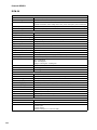
Specifications/Technische Daten . . . . . . . . . . . . . . . . . . . . . . . . . . . . . . . . . . . . . . . . . . . . . . . 134
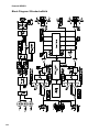
Block Diagram / Blockschaltbild . . . . . . . . . . . . . . . . . . . . . . . . . . . . . . . . . . . . . . . . . . . . . . . . 138
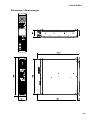
Dimensions / Abmessungen . . . . . . . . . . . . . . . . . . . . . . . . . . . . . . . . . . . . . . . . . . . . . . . . . . . 139
3
PowerH SERIES
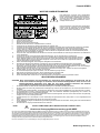
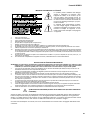
IMPORTANT SAFETY INSTRUCTIONS
The lightning flash with arrowhead symbol, within an equilateral
triangle is intended to alert the user to the presence of uninsulated
”dangerous voltage” within the product’s enclosure that may be of
sufficent magnitude to constitute a risk of electric shock to persons.
The exclamation point within an equilateral triangle is intended to
alert the user to the presence of important operating and
maintance (servicing) instructions in the literature accompanying
the appliance.
1.
2.
3.
4.
5.
6.
7.
8.
9.
10.
11.
12.
13.
14.
15.
16.
17.
18.
19.
Read these instructions.
Keep these instructions.
Heed all warnings.
Follow all instructions.
Do not use this apparatus near water.
Clean only with a dry cloth.
Do not cover any ventilation openings. Install in accordance with the manufacturer’s instructions.
Do not install near heat sources such as radiators, heat registers, stoves, or other apparatus (including amplifiers) that produce heat.
Do not defeat the safety purpose of the polarized or the grounding-type plug. A polarized plug has two blades with one wider than the other. A grounding type plug
has two blades and a third grounding prong. The wide blade or the third prong are provided for your safety. If the provided plug does not fit into your outlet, consult
an electrician for replacement of the obsolete outlet.
Protect the power cord from being walked on or pinched particularly at plugs, convenience receptacles, and the point where they exit from the apparatus.
Only use attachments/accessories specified by the manufacturer.
Use only with the cart, tripod, bracket, or table specified by the manufacturer, or sold with the apparatus. When a cart is used, use caution when
moving the cart/apparatus combination to avoid injury from tip-over.
Unplug this apparatus during lightning storms or when unused for a long period of time.
Refer all servicing to qualified service personnel. Servicing is required when the apparatus has been damaged in any way, such as power-supply
cord or plug is damaged, liquid has been spilled or orbjects have fallen into the apparatus, the apparatus has been exposed to rain or moisture,
does not operate normally, or has been dropped.
Do not expose this equipment to dripping or splashing and ensure that no objects filled with liquids, such as vases, are placed on the equipment.
To completely disconnect this equipment from the AC Mains, disconnect the power supply cord plug from the AC receptacle.
The mains plug of the power supply cord shall remain readily operable.
No naked flame sources, such as lighted candles, should be placed on the apparatus.
The product should be connected to a mains socket outlet with a protective earthing connection.
IMPORTANT SERVICE INSTRUCTIONS
CAUTION: These servicing instructions are for use by qualified personnel only. To reduce the risk of electric shock, do not
perform any servicing other than that contained in the Operating Instructions unless you are qualified to do so.
Refer all servicing to qualified service personnel.
1.
2.
3.
4.
5.
6.
7.
8.
Security regulations as stated in the EN 60065 (VDE 0860 / IEC 65) and the CSA E65 - 94 have to be obeyed when servicing the appliance.
Use of a mains separator transformer is mandatory during maintenance while the appliance is opened, needs to be operated and is connected to the mains.
Switch off the power before retrofitting any extensions, changing the mains voltage or the output voltage.
The minimum distance between parts carrying mains voltage and any accessible metal piece (metal enclosure), respectively between the mains poles has to be 3
mm and needs to be minded at all times. The minimum distance between parts carrying mains voltage and any switches or breakers that are not connected to the
mains (secondary parts) has to be 6 mm and needs to be minded at all times.
Replacing special components that are marked in the circuit diagram using the security symbol (Note) is only permissible when using original parts.
Altering the circuitry without prior consent or advice is not legitimate.
Any work security regulations that are applicable at the locations where the appliance is being serviced have to be strictly obeyed. This applies also to any regulations
about the work place itself.
All instructions concerning the handling of MOS-circuits have to be observed.
NOTE:
SAFETY COMPONENT (MUST BE REPLACED BY ORIGINAL PART)
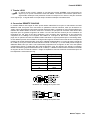
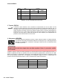
WEEE RECYCLING/DISPOSAL INSTRUCTIONS
The Wheelie Bin symbol found on the product or in the manual indicates that this product must not be disposed of with other waste. It is in our category the
manufacturer’s responsibility to properly dispose of their waste electrical and electronic equipment (WEEE) at the end of its life. Due to the differences in
each EU country’s management of WEEE, please contact your local distributor. We are committed to facilitate our own electronic-waste-management-system,
for the free of charge return of all EVI Audio GmbH products: Telex, Dynacord, ElectroVoice, Midas Consoles, KlarkTeknik and RTS. Arrangements are made
with the dealer where you purchased the equipment from, for the returning of all unusable equipment at no cost, to the factory in Straubing, for environmental
protective disposal.
Due to line current harmonics, we recommend that you contact your supply authority before connection.
4
Owner’s Manual
PowerH SERIES
1 Introduction
1.1 Welcome
Dynacord’s new PowerH SERIES power amps herald a new age in power amplifier technology. These
highly efficient PowerH amplifiers combine uncompromising audio performance with low weight and
highest reliability. Optionally available remote control modules provide the possibility to completely control
and monitor the power amps via IRIS-Net.
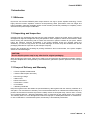
1.2 Unpacking and Inspection
Carefully open the packaging and take out the power amplifier. Inspect the power amp’s enclosure for
damages that might have happened during transportation. Each amplifier is examined and tested in detail
before leaving the manufacturing site to ensure that it arrives in perfect condition at your place. Please
inform the transport company immediately, if the power amplifier shows any damage. Being the
addressee, you are the only person who can claim damages in transit. Keep the cardboard box and all
packaging materials for inspection by the transport company.
Keeping the cardboard box including all packing materials is also recommended, if the power amplifier
shows no external damages.
CAUTION:
Do not ship the power amp in any other but its original packaging.
When shipping the power amp, make sure to always use its original box and packaging materials. Packing
the power amplifier like it was packed by the manufacturer guarantees optimum protection from transport
damage.
1.3 Scope of Delivery and Warranty
•
1 Power Amplifier H2500/H5000
•
1 Owner’s Manual (this document)
•
2 Phoenix-type Plugs
•
1 Mains Cord
•
2 Rack-mount Ears
•
4 Case Nuts + screws
•
4 Foot Stands
•
1 Warranty Certificate
Keep the original invoice that states the purchase/delivery date together with the warranty certificate at a
safe place. The manufacturer‘s warranty covers all substantial defects in materials and workmanship for a
period of 36 months from the date of purchase. Liability claims are accepted solely, when a valid - correctly
and completely filled out - Warranty Registration Form is presented by the original owner of the product.
The warranty does not cover damage that results from improper or inadequate treatment or maintenance.
In case of alteration or unauthorized repairs, the warranty is automatically terminated.
Owner’s Manual
5
PowerH SERIES
1.4 Features and Description
The power amp H2500/H5000 is part of Dynacord’s new PowerH SERIES, which marks a milestone in the
design and the production of high-performance power amplifiers. The innovative 3-stage Grounded Bridge
Class H Topology with “floating” switching power supply unit offers very high and stable output with
extreme high efficiency on an extremely high performance level at minimum weight. PowerH amps are
ideal for driving professional touring, high-end Concert-Sound and Pro-Sound applications.
Next to classical protections, this new design employs the multi-stage ATP system (Advanced Thermal
Protection) for the first time, which in most cases prevents the power amplifier from switching off when the
temperature exceeds a critical level. The newly designed MCS system (Mains Current Supervision)
prevents power amplifier breakdown caused by the activation of the automatic circuit breaker.
For this, among other things, the MCS system uses the highly precise measurement of the RMS value of
the actual mains current consumption. Information about the status of the power amplifier and its internal
protections is provided on a LC-display. By utilizing the optionally available remote control module that is
compatible with IRIS-Net, this power amplifier additionally offers comprehensive remote monitoring and
remote control functions plus a universal 2-channel digital audio controller (DSP) including highly precise
FIR-filtering and digital speaker protection algorithms.
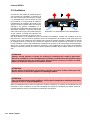
1.5 Responsibility of the User
Speaker System Damage
PowerH power amps provide extremely high power output that might be dangerous for human beings as
well as for the connected speaker systems. High output voltages can damage or even destroy the
connected speaker systems, especially, when the PowerH amplifier is operated in bridged mode. Prior to
connecting any loudspeakers, make sure to check the speaker system’s specifications for continuous and
peak power handling capacities. Even if amplification has been reduced through lowering the input level
controls on the amplifier’s front panel, it is still possible to achieve full power output with a sufficiently high
input signal.
Dangers at the Loudspeaker/Power Outputs
PowerH amplifiers are capable of producing dangerously high voltage output that is present at the output
connectors. To protect yourself from electric shock, do not touch any blank speaker cables during
operation of the power amp.
HF-Interference
This equipment has been tested and found to comply with the limits for a Class B digital device, pursuant
to Part 15 of the FCC Rules. These limits are designed to provide reasonable protection agains harmful
interference in a residential installation. This equipment generates, uses and can radiate radio frequency
energy and, if not installed and used in accordance with the instructions, may cause harmful interference
to radio communications. However, there is no guarantee that interference will not occur in a particular
installation. If this equipment does cause harmful interference to radio or televsion reception, which can be
determined by turning the equipment off and on, the user is encouraged to try to correct the interference by
one or more of the following measures:
6
•
Reorient or relocate the receiving antenna
•
Increase the separation between the equipment and receiver
•
Connect the equipment into an outlet on a circuit different from that to which the receiver is connected
•
Consult the dealer or an experienced radio/TV technician for help
Owner’s Manual
PowerH SERIES
2 Installation
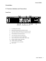
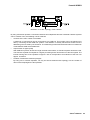
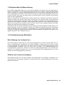
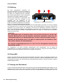
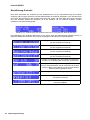
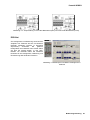
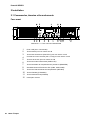
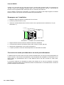
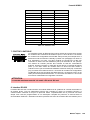
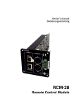
2.1 Controls, Indicators and Connections
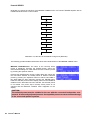
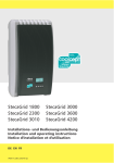
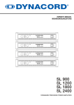
Front View
Illustration 2.1: H2500/H5000 front view
1
2
3
4
5
6
7
8
9
10
11
12
LC-Display (with controls)
Muting Indicator (MUTE) for channels A and B
Protections Indicator (PROTECT) for channels A and B
Input Level Control (CH A, CH B) for channels A and B
Level Indicators for channels A and B
Audio Input Mode Indicator (PARALLEL)
Power Amplifier Mode Indicator (BRIDGED)
Input Sensitivity/Gain Indicator (0dBu, 35dB, 32dB)
Remote Amplifier Indicator (IRIS-Net)
Standby Indicator (STANDBY)
Power On/Off Indicator (POWER)
Mains Switch
Owner’s Manual
7
PowerH SERIES
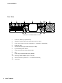
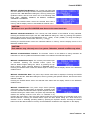
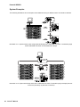
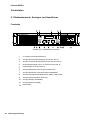
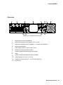
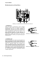
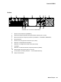
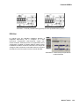
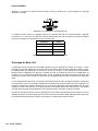
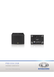
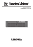
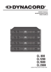
Rear View
Illustration 2.2: H2500/H5000 rear view
8
1
2
3
4
PowerCon Mains Input (MAINS IN)
5
6
7
8
9
10
11
12
XLR and Phoenix-Type Audio Inputs (IN A, IN B)
Owner’s Manual
Speakon Female-Type Power Amp Outputs (CH A, CH B)
Power Amp Output Terminals (CHANNEL A, CHANNEL B, BRIDGED)
Expansion Slot
Input Sensitivity/Gain Switch
Audio Inputs Routing Switch (ROUTING)
Fan
Power Amp Outputs Mode Switch (MODE)
XLR-Type Audio Outputs (OUT A, OUT B)
Ground Lift Switch (CIRCUIT TO CHASSIS SWITCH)
Type Plate
PowerH SERIES
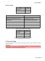
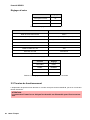
Factory Settings
Control
Setting
Mains Switch
off
Level CH A
0dB
Level CH B
0dB
Table 2.1: Factory Settings of the Controls
Parameter
Value
Power-On-Delay
0.00 s
Breaker Current (dependent on the mains)
16 A (230 V) / 30 A (120 V)
Amplifier Name
Dynacord H2500 or Dynacord H5000
LCD Contrast
50%
LCD Brightness High
90%
LCD Brightness Low
40%
LCD Time to Dim
Autodim off
Temperature Unit
°C
Table 2.2: Factory Settings of the LC-Display
Controls
Setting
ROUTING
DUAL
MODE
NORMAL
SENSITIVITY/GAIN
0dBu
GROUNDLIFT
GROUNDED
Table 2.3: Factory Settings of the Rear Panel Controls
2.2 Operating Voltage
The power amplifier receives its power supply via the MAINS IN connector, which is designed as a Neutrik
PowerCon connector.
CAUTION:
The PowerCon is a connector without breaking capacity, i.e. the PowerCon should not
be connected or disconnected under load or live.
Owner’s Manual
9
PowerH SERIES
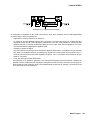
During installation, always separate the power amplifier from the mains. Connect the power amplifier only
to a mains network, which corresponds to the requirements indicated on the type plate.
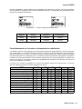
Illustration 2.3: H2500/H5000 type plate
Device
Voltage
Frequency
Power Consumption
H2500
100-240 V
50-60 Hz
1000 W
H5000
100-240 V
50-60 Hz
1450 W
Table 2.4: Specifications for the Power Supply Unit
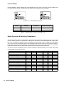
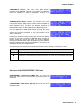
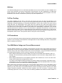
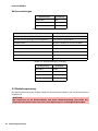
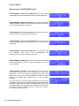
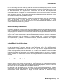
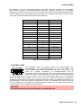
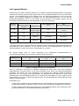
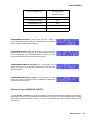
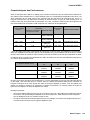
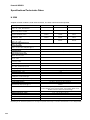
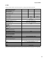
Mains Operation & Resulting Temperature
The following tables allow the determination of power supply and cabling requirements. The power drawn
from the mains network is converted into output power to feed the connected loudspeaker systems and
into heat. The difference between power consumption and dispensed power is called power dissipation
(Pd). The amount of heat resulting from power dissipation might remain inside of a rack-shelf and needs to
be diverted using appropriate measures. The following table is meant as auxiliary means for calculating
temperatures inside of a rack-shelf system/cabinet and the ventilation efforts necessary.
The column Pd lists the leakage power in relation to different operational states. The column BTU/hr lists
the dispensed heat amount per hour.
H2500
Imains in A
Pmains in W
Pout in W
Pd in W1
BTU/hr2
-
70
239
230
0.7
70
3
Max. Output Power @ 8
230
15.3
2420
2 x 850
720
2457
Max. Output Power @ 4 3
230
25.7
4300
2 x 1450
1400
4777
3
1/3 Max. Output Power @ 4
230
14.7
2325
2 x 483
1358
4635
1/8 Max. Output Power @ 4 3
230
6.2
875
2 x 181
513
1749
4
230
6.7
1000
2 x 181
588
2005
45
253
7.1
1105
2 x 219
666
2274
Idle
1/8 Max. Output Power @ 4
1/8 Max. Output Power @ 4
3
230
5.6
775
2 x 145
485
1655
230
23.5
3900
2 x 1200
1500
5118
230
16.7
2665
2 x 600
1465
4999
230
39.6
6920
2 x 2000
2920
9963
3
230
9.1
1345
2 x 238
870
2969
4
230
9.1
1335
2 x 238
860
2934
Normal Mode (-10 dB) @ 4
Rated Output Power (0 dB) @ 4
Alert (Alarm) Mode (-3 dB) @ 4
3
Max. Output Power @ 2
1/8 Max. Output Power @ 2
1/8 Max. Output Power @ 2
10
Umains in V
Owner’s Manual
3
3
PowerH SERIES
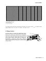
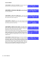
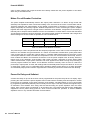
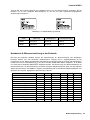
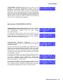
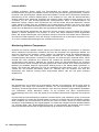
H5000
Idle
Max. Output Power @ 8
3
Umains in V
Imains in A
Pmains in W
Pout in W
Pd in W1
230
0.7
78
-
78
266
230
24.5
4089
2 x 1500
1089
3716
BTU/hr2
230
40.9
7137
2 x 2500
2137
7292
3
230
18.1
2927
2 x 833
1260
4300
3
230
6.2
877
2 x 313
252
860
4
230
9.6
1450
2 x 313
806
2750
4 5
253
11.6
1944
2 x 378
1188
4053
230
9.2
1368
2 x 250
868
2962
230
37.5
6445
2 x 2100
2245
7660
230
22.7
3760
2 x 1050
1660
5664
230
44.3
8180
2 x 3500
1180
4026
1/8 Max. Output Power @ 2 3
230
15.3
2427
2 x 438
1552
5296
4
230
13.6
2105
2 x 438
1230
4197
Max. Output Power @ 4 3
1/3 Max. Output Power @ 4
1/8 Max. Output Power @ 4
1/8 Max. Output Power @ 4
1/8 Max. Output Power @ 4
Normal Mode (-10 dB) @ 4 3
Rated Output Power (0 dB) @ 4
Alert (Alarm) Mode (-3 dB) @ 4
3
Max. Output Power @ 2
1/8 Max. Output Power @ 2
3
3
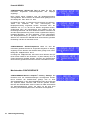
1. Pd = Power Dissipation
2. 1 BTU = 1055.06 J = 1055.06 Ws
3. Sine Modulation (1 kHz)
4. Pink-Noise EN60065 / 7. Edition
5. 10 % Mains Over Voltage
The following factors allow direct proportional calculation of the mains current Imains for different mains
supply voltages: 100 V = 2.3, 120 V = 1.9, 220 V = 1.05, 240 V = 0.97.
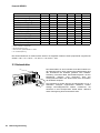
2.3 Mains Switch
The Mains Switch on the front panel separates the power
amp from the mains. Pressing the Mains Switch starts
booting up the power amp. A soft start circuit compensates
mains inrush current peaks and thus prevents the automatic
cutout of the mains from reacting when switching on the
power amplifier. Speaker system switch-on is delayed by
approximately 2 seconds via output relays, effectively
suppressing any possible power-on noise, which otherwise
might be heard through the loudspeakers. MUTE-LED light
during this delay.
Owner’s Manual
11
PowerH SERIES
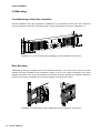
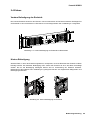
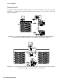
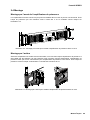
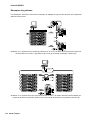
2.4 Mounting
Front Mounting of the Power Amplifier
PowerH amplifiers have been designed for installation in a conventional 19-inch rack case. Attach the
power amp with its frontal rack mount ears using 4 screws and washers as shown in illustration 2.4.
Illustration 2.4: Front mounting when installing the power amplifier in a rack case
Rear Mounting
Additionally securing the amplifier at the rear becomes necessary, if the rack case in which the power
amplifier has been installed will be transported. Failure to do so may result in damage to the power
amplifier as well as to the rack case. Brackets for securing the power amplifier are supplied. Attach the
power amp as shown in illustration 2.5 using the supplied 4 case nuts and screws.
Illustration 2.5: Rear mounting when installing the power amplifier in a rack case
12
Owner’s Manual
PowerH SERIES
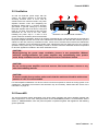
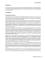
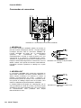
2.5 Ventilation
As with all Dynacord power amps with fan
cooling, the airflow direction is front-to-rear,
obviously because there is more cold air
outside of the rack case than inside. The power
amplifier remains cooler and dissipating the
developing waste heat in a specific direction
gets easier. In general, setting up or mounting
the power amplifier has to be done in a way that
fresh air can enter unhindered at the front and
exhausted air can exit at the rear. When
installing the power amp in a case or rack
Illustration 2.6: H2500/H5000 Ventilation
system, attention should be paid to these details
to provide sufficient ventilation. Allow for an air duct of at least 60 mm x 330 mm between the rear panel of
the power amplifier and the inner wall of the cabinet/rack case. Make sure that the duct reaches up to the
cabinet’s or the rack case’s top ventilation louvers. Leave room of at least 100 mm above the cabinet/rack
case for ventilation. Since temperatures inside of the cabinet/rack case can easily rise up to 40 °C during
operation of the power amp, it is mandatory to bear in mind the maximum allowable ambient temperature
for all other appliances installed in the same cabinet/rack case.
CAUTION:
Blocking/closing the power amp’s ventilation louvers is not permissible. Without
sufficient cooling/ventilation, the power amplifier may automatically enter protect
mode. Keep ventilation louvers free from dust to ensure unhindered airflow.
CAUTION:
Do not use the power amplifier near heat sources, like heater blowers, stoves or any
other heat radiating devices.
CAUTION:
To ensure trouble-free operation, make certain that the maximum allowable ambient temperature of +40 °C is not exceeded.
For fixed amplifier installations in a device control room that incorporate a central air-cooling system or air
conditioners, calculating the maximum heat emission may be necessary. Please also take notice of the
information on page 10.
2.6 Groundlift
The ground lift switch allows eliminating noise loops. When operating the power amplifier together with
other equipment in a rack case, setting the switch to the GROUNDED position is recommended. Set the
switch to UNGROUNDED, when the power amplifier is operated together with appliances with differing
ground potentials.
Owner’s Manual
13
PowerH SERIES
2.7 Indication of the Operation Mode
Two LEDs on the power amp’s front panel indicate the currently selected mode of operation. The
PARALLEL-LED lights yellow, when the ROUTING switch is set to PARALLEL. The PARALLEL LED does
not light, when the switch is set to DUAL. The BRIDGED LED lights yellow, when the MODE switch is set
to BRIDGED. The BRIDGED LED does not light, when the switch is set to NORMAL.
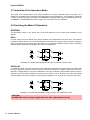
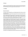
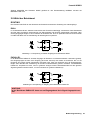
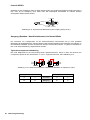
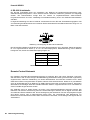
2.8 Selecting the Mode Of Operation
ROUTING
The ROUTING switch on the power amp’s rear panel defines how the audio inputs handle the input
signals.
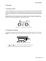
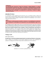
DUAL
In DUAL mode, the two channels of the power amplifier work independent from each other. This mode of
operation is being used for all 2-channel applications, like stereo or Bi-Amp (active) operation. Using the
input level controls on the power amp’s front panel or an optionally available remote control module and
IRIS-Net allows independently adjusting the channels’ amplification.
Illustration 2.7: Audio signal applied to both input connectors in DUAL mode
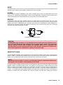
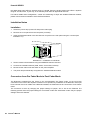
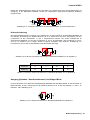
PARALLEL
In PARALLEL mode, the inputs of channel A and channel B are directly electrically linked. The audio signal
has to be applied to the input connectors (XLR or Phoenix) of channel A. Using the input level controls or
IRIS-Net to independently control the amplification of the two channels is still possible because only the
channels’ inputs are linked. PARALLEL operation is the mode of choice, whenever the same input signal
drives multiple power amp channels of a large system installation, e.g. when driving massive bass arrays.
Illustration 2.8: Audio signal applied to input connector A in PARALLEL mode
CAUTION:
In PARALLEL mode, the input signal has to be fed to input channel A only.
14
Owner’s Manual
PowerH SERIES
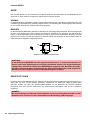
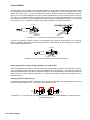
MODE
The MODE switch on the power amp’s rear panel defines the operation mode of the power amplifier blocks
and thus, how a single or more speaker systems have to be connected.
NORMAL
In two-channel operation (NORMAL), both power amplifier blocks work as independent power amp
channels and controlling the amplification of each channel separately is possible. How the power amp’s
audio inputs handle input signals depends only on the setting of the ROUTING switch.
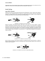
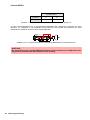
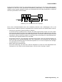
BRIDGED
In BRIDGED mode, the power amplifier functions as single-channel, monaural power amp. The audio
signal has to be applied to either one of the input connectors (XLR or Phoenix) of channel A while channel
B inputs are inactive. In BRIDGED mode, the power amp channel A is modulated as usual.In addition, the
input signal is internally inverted and applied to channel B. The A and B power amps act in push-pull
operation delivering doubled output voltage.
Illustration 2.9: BRIDGED mode
CAUTION:
In BRIDGED mode operation, it is not allowable for the load connected to fall below a value of 4 ohms. Extremely high voltages can be present at the output. The connected
speaker systems must be able to handle such voltages. Make sure to completely read
and fully observe power rating specifications of the speaker systems to be used and to
check them against the output power capacity of the power amp.
SENSITIVITY/GAIN
PowerH SERIES amplifiers can be operated at an input sensitivity of 0dBu as well as at a constant gain of
35dB or 32dB. A correspondingly labeled LED on the power amp’s front panel indicates the respective
setting of the sensitivity/gain switch, which is located on the power amp’s rear panel.
NOTE:
If a remote control module is used the sensitivity/gain switch is deactivated and the sensitivity/gain of the amplfier is automatically set to 35 dB.
An Input sensitivity of 0dBu means that with an input signal of 0 dBu (0.775 Vrms), the signal at the power
amplifier outputs is at Rated Output Power. This setting is recommended for audio signal sources that
deliver a nominal output voltage of 0 dBu. As an alternative, operating the power amp at a constant gain of
35 dB or 32 dB is also possible. Operating all power amps in a setup – even those of different performance
classes – at constant gain setting greatly simplifies the adjustment of signal processors. This allows the
installer to consider each power amplifier with a gain of 35 dB (or 32 dB) when setting gain structure,
Owner’s Manual
15
PowerH SERIES
independent of the actual maximum output capacity of each individual power amp. Any limiters have to be
adjusted to maximum power handling capacity of the loudspeaker components.
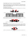
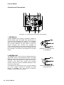
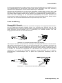
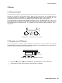
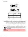
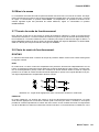
Audio Cabling
Input (XLR / Phoenix)
Inputs IN A and IN B are electronically balanced and the SENSITIVITY switch controls input sensitivity.
Connection can be established either by using XLR- or Phoenix-type connectors, which are connected in
parallel. The needed Phoenix-type connectors are supplied with the power amplifier. The pin-assignment
of XLRF-type connectors is in accordance with the IEC standard 268.
2, HOT
3, COLD
1, SHIELD
Illustration 2.10: Balanced connection of input
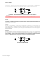
Whenever possible, using balanced audio signal feeds at the input of the power amplifier is always
preferred. Unbalanced connections should only be used if the cables are very short and no interfering
signals are to be expected in the vicinity of the power amplifier. In this case, bridging the screen (shielding)
and the pin of the inverting input inside of the connector is mandatory. Otherwise, a 6 dB drop in level
could result. Please also see illustration 2.11. Due to their immunity against external interference sources,
such as dimmers, mains connections, HF-control lines, etc., using balanced cabling and connections is
always preferable.
2, HOT
3, COLD
JUMPER
FROM COLD
TO SHIELD
Illustration 2.11: Unbalanced connection of input
Next to its input connector, each channel provides an individual XLR-type connector (OUT A or OUT B),
which is connected in parallel to allow for comfortably daisy-chaining the audio signal for the connection of
additional audio equipment.
1, SHIELD
3, COLD
2, HOT
Illustration 2.12: Balanced connection of output (Daisy-Chain)
16
Owner’s Manual
PowerH SERIES
Output (Speakon-type Connectors / Terminals) in Normal Mode
With PowerH SERIES amplifiers speaker connection differs depending on the actually selected mode of
operation of the power amplifier blocks, i.e. the setting of the MODE switch on the power amp’s rear panel.
In NORMAL mode, the loudspeaker systems can be connected in two different ways: using typical
Speaker Systems Cabling or Bi-Amp Cabling.
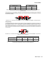
Typical Speaker System Cabling
The first possibility is to use the two Speakon-type connectors, whereas speakers have to be connected to
pins 1+ and 1– of the sockets, see illustration 2.13.
Illustration 2.13: Speaker connection in NORMAL operation mode, using Speakon A and B connectors
Speakon CH B
Speakon CH A
1+
1-
Connector
1+
1-
B+
B-
Assignment
A+
A-
Table 2.5: Speaker connection in NORMAL operation mode, using Speakon A and B connectors
Next to the Speakon-type sockets, conventional speaker terminals are provided as well. The following
illustration shows how to connect the speaker systems for NORMAL mode operation.
Illustration 2.14: Speaker connection in NORMAL operation mode, using Terminals
Bi-Amp Cabling
The second possibility for connecting the speakers when the power amplifier is operated in NORMAL
mode is to only use the Speakon-type connector CH A and to connect one speaker cabinet to pins 1+ and
1–, as described above and the second cabinet to pins 2+ and 2– as shown in illustration 2.15. Only pins
2+ and 2– of the Speakon CH A connector are assigned. Proceeding like this facilitates the cabling of
speaker systems that are used in active 2-way operation (Bi-Amp).
1+
+
2
+
CHANNEL A
2
2-
1-
CH A 2+
CHANNEL B
Illustration 2.15: Bi-Amp speaker connection in NORMAL operation mode, using only the Speakon A connector
Owner’s Manual
17
PowerH SERIES
Speakon CH A
Connection Pin
1+
1-
2+
2-
Channel Assignment
A+
A-
B+
B-
Table 2.6: Bi-Amp speaker connection in NORMAL operation mode, using only the Speakon A connector
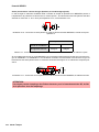
Output (Speakon-type Connectors / Terminals) in Bridged Mode
Setting the MODE switch on the power amp’s rear panel to BRIDGED lets the power amplifier run in
bridged mode operation and speaker connection has to be established using pins 1+ and 2+ of the
Speakon socket CH A, see illustration 2.16.
Illustration 2.16: Speaker connection in BRIDGED operation mode, using Speakon A
Speakon CH A
Connection Pin
1+
2+
Channel Assignment
Bridged+
Bridged-
Table 2.7: Speaker connection in BRIDGED operation mode, using Speakon A
When using the speaker terminals in BRIDGED mode, the loudspeaker system has to be connected to the
red terminals of CHANNEL A and CHANNEL B. An illustration of how to correctly establish speaker
connection for this mode of operation is provided on the power amp’s enclosure.
Illustration 2.17: Speaker connection in BRIDGED operation mode, using Terminals
CAUTION:
Due to the high current, using banana plugs for speaker connection is not permissible.
18
Owner’s Manual
PowerH SERIES
3 Operation
3.1 Volume Control
In DUAL and PARALLEL mode, the level controls CH A and CH B on the power amp’s front panel are used
to control the amplification of the corresponding channel. Turning the control to the right increases and
turning it to the left decreases the volume. In BRIDGED mode operation, the output volume of the power
amp is only controlled by the CH A level control. Any changes in the setting of the CH B level control are
ignored.
With an installed remote control module, the level controls CH A and CH B may be deactivated, i.e.
controlling the power amp’s amplification is only possible via IRIS-Net. The Level Controls Off !
indicator on the LC display signals that the controls are deactivated.
Illustration 3.1: Level controls CH A and CH B
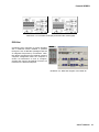
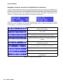
3.2 Graphical LC display
The graphical LC display provides detailed information about the operating status of the power amplifier.
Furthermore, it is possible to change several settings of the power amp and, if installed, of a remote control
module.
Illustration 3.2: LC display with controls
1
Up
2
ENTER button: Pressing this key selects the highlighted menu entry.
/ Down
buttons: These keys allow navigating through the menu.
Owner’s Manual
19
PowerH SERIES
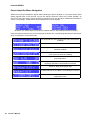
Power Amplifier Menu Navigation
Start screen and type designation appear after switching the power amplifier on. The power amp’s status
display appears after a few seconds. The top line always shows the name of the power amplifier. An
overview of the power amp’s actual condition is provided in lines two and three. Additional information is
shown if, for example, a RCM-26 has been installed in the power amplifier.
Illustration 3.3: Status display of the power amplifier without / with RCM-26 installed (example)
Using the Up/Down buttons lets you scroll through the bottom line. The following table lists the information,
which is displayed in consecutive order.
Set CAN address and CAN baud rate (only with RCM-26
installed)
Name of the actual preset (only with RCM-26 installed)
Currently used audio input of the power amp (only with
RCM-26 installed)
Status of the input level controls on the power amp’s front
panel (only with RCM-26 installed)
Mains voltage, mains current consumption (RMS) and
amp temperature.
Currently active parameters for the mode of operation,
sensitivity and Mains Circuit Breaker Protection
Power-on delay of the power amp
Actual parameter for the Mains Circuit Breaker Protection
Pressing the ENTER button branches to the CONFIG
configuration menu.
Table 3.1: Overview status display
20
Owner’s Manual
PowerH SERIES
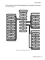
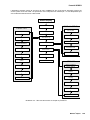
The following illustration shows the structure of the CONFIG menu (and its associated submenus) when
opening it from the status display. Menu entries marked with an asterisk * are only available when the
remote control module is not installed.
Status display
Power-On-Delay
EVENT LOG
DISPLAY SETUP
LCD Contrast
Counter POWER UP
Breaker Current
Counter AMP ON
Show Event Log
Counter PROTECT
Menu Display
LCD Brightness
LCD Time to Dim
Temperature Unit
Counter AMP MUTE
Menu Service
BACK
Counter MAINS FAIL
Amplifier Name*
Uptime
EXIT
SERVICE
Show Event History
Restore Amplifier’s
Factory Settings
Reset Event Log
Lifetime
BACK
Last Log
Module Signature
Firmware Version
BACK
Illustration 3.4: The power amp’s menu structure
Owner’s Manual
21
PowerH SERIES
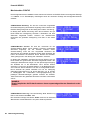
Structure of the CONFIG menu
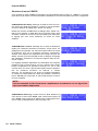
Entering the CONFIG menu is possible through pressing the ENTER button while the entry
>> CONFIG << is highlighted in the status display. The following provides detailed information about the
individual items of the configuration menu.
CONFIG/Power-On-Delay: The power amp’s currently set poweron delay is shown. Pressing the ENTER-Taste button opens the
Set Power-On-Delay dialog box.
Using the Up/Down buttons in the Set Power-On-Delay lets
the user specify a delay in the range of 0 seconds to up to 6.35
seconds. Pressing the ENTER button again stores the previously
made setting and the display returns to the CONFIG menu.
CONFIG/Breaker Current: The actually set value of the current
that controls the Mains Circuit Breaker Protection is displayed.
The set current has to match the value of the power amp’s internal
fuse for the protection to work correctly. Please refer to the
explanations on page 32 for more details. Pressing the ENTER
button opens the Set Breaker Current dialog box where the
desired value for the breaker current can be set.
The valid value ranges depend on the power amp’s power supply.
Currents between 6 A and 40 A can be set when the power
amplifier is operated at 120 V. Currents between 6 A and 30 A can
be set when the power amplifier is operated at 220-240 V. Select
Factory 30 A or Factory 16 A for automatic setting
depending on the power amp’s power supply. Pressing the
ENTER button stores the selected current value in memory and
the CONFIG menu reappears on the display.
NOTE:
Operating the power amplifier on a separately fused mains power line is recommended
only.
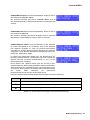
CONFIG/Show Event Log: The menu entry Show Event Log
leads to the EVENT LOG submenu. The individual entries in the
EVENT LOG menu are explained in detail in the paragraph
Structure of the CONFIG.EVENT LOG menu (see page 23).
CONFIG/Menu Display: The menu entry Menu Display leads to
the
DISPLAY SETUP
submenu.
Each
entry
in
the
DISPLAY SETUP menu is explained in detail in paragraph
Structure of the CONFIG/DISPLAY SETUP menu (see page 24).
22
Owner’s Manual
PowerH SERIES
CONFIG/Menu Service: The menu entry Menu Service
branches to the SERVICE submenu. The entries in the SERVICE
menu are explained in detail in paragraph Structure of the
CONFIG/SERVICE menu (see page 26).
CONFIG/Amplifier Name: Displays the name of the power
amplifier. The menu entry only exists when no RCM-26 is installed
in the power amplifier. With a remote control module installed, the
power amplifier has to be named via IRIS-Net. Pressing the
ENTER button opens the Set Amplifier Name dialog box.
The Set Amplifier Name dialog allows changing the power
amp’s name, which can be composed of a maximum of 20
symbols and consist of all letters a-z, A-Z, the numbers 0-9 and
special characters.
Pressing the Up/Down buttons locates the cursor at the desired
position of the name. Pressing the ENTER button accepts the
desired symbol and moves the cursor to the next character.
Pressing the ENTER button after manipulating the last character,
stores the desired name of the power amplifier in the memory and
the display returns to the CONFIG menu.
The following special characters provide special functions when entering a power amp’s name:
Character
Function
Accepts the entered name and returns to the menu.
Deletes the currently selected symbol and moves the cursor by one character to the right.
Set the cursor by one character to the left.
Table 3.2: Functions of special characters when entering the power amp’s name
Structure of the CONFIG/EVENT LOG menu
CONFIG/EVENT LOG/Counter POWER UP: This menu item
shows how many times the power switch on the front panel has
been used.
CONFIG/EVENT LOG/Counter AMP ON: This menu item shows
how often the power amplifier has been activated from the OFF or
STANDBY state.
Owner’s Manual
23
PowerH SERIES
CONFIG/EVENT LOG/Counter PROTECT: This item shows how
many times one of the protections has been activated.
CONFIG/EVENT LOG/Counter AMP MUTE: This menu item
shows how often the power amp’s output signal has been muted by
one of the protections.
CONFIG/EVENT LOG/Counter MAINS FAIL: This menu item
shows how many times over- or undervoltage has been recognized
at the power amp’s power supply unit.
CONFIG/EVENT LOG/Uptime: This menu item shows the total
running time of the power amplifier (not counting standby times)
since the last reset of the Event Log.
CONFIG/EVENT LOG/Show Event History: The Show Event
History menu entry opens a list of all events in chronological order
(last event shown first) that have been registered. Pressing the
ENTER button selects the desired item in the list.
Point in time and cause of the occurrence is shown for each item
in the list. The state of operation of the amplifier (Amp) and the two
output channels (Ch A or Ch B) is indicated for each event.
Pressing the Up/Down buttons lets the user scroll through the list
of entries. Pressing the ENTER button lets one return to the
CONFIG menu.
CONFIG/EVENT LOG/Reset Event Log: The user can completely
reset the Event Log of the power amplifier in this menu entry. All
counters are reset to zero and the event log is deleted. Pressing
the ENTER button opens a safety dialog box that lets the user
choose between YES or NO by pressing the Up/Down buttons. If
YES has been selected, pressing the ENTER button resets the
Event Log. If the user decides to select NO, the Event Log stays
unchanged and the CONFIG. menu reappears on the display.
24
Owner’s Manual
PowerH SERIES
Structure of the CONFIG/DISPLAY SETUP menu
CONFIG/DISPLAY SETUP/LCD Contrast: This menu item
indicates the currently set contrast of the LC display. Pressing the
ENTER button opens the Set LCD Contrast where the user
can select a contrast setting in the range of 0 % to 100 % by using
the Up/Down buttons. Pressing the ENTER button again stores
the selected value for contrast in memory and the CONFIG menu
reappears on the display.
CONFIG/DISPLAY SETUP/LCD Brightness: The currently set
maximum and minimum values for display brightness are
indicated. The maximum value represents the brightness of the
display that is used during normal operation. The minimum value
represents the brightness of the display that it is adjusted to after a
specific period of time, if desired.
Pressing the ENTER button opens the Set Brightn. Hi-Lvl
dialog box, which, by pressing the Up/Down buttons, allows
setting the undimmed display brightness in a range of 50 % to
100 %.
Pressing the ENTER button stores the set brightness value in
memory and the display indication changes to the
Set Brightn. Lo-Lvl dialog box, where pressing the Up/
Down buttons allows setting the dimmed display brightness in a
range of 0 % to 80 %. Pressing the ENTER button again stores
the set brightness value and the display returns to the CONFIG
menu.
CONFIG/DISPLAY SETUP/LCD Time to Dim: The currently set
time interval, during which the display lights with the maximum
brightness it has been set to, is indicated. After the time interval
has expired the display is dimmed.
Pressing the ENTER button opens the Set LCD Time to Dim
dialog box, where the user can specify the duration after which the
display dimming starts by pressing the Up/Down buttons. The
duration can be set to 4, 8, 16, 32 or 64 minutes. Alternately, the
user can select Autodim off to completely deactivate the
dimming function, which results in the display always lighting at
the set maximum brightness level (Brightn. Hi-Lvl).
For an increased lifetime of the display, activating the dimming
function is recommended. Pressing the ENTER button stores the
settings in memory and the display returns to the CONFIG menu.
Owner’s Manual
25
PowerH SERIES
CONFIG/DISPLAY SETUP/Temperature Unit: The currently
selected unit for the indication of temperature values is displayed.
Pressing the ENTER button opens the Set Temperature Unit
dialog box, which allows selecting °C (Degrees Celsius) or °F
(Degrees Fahrenheit) by pressing the Up/Down buttons. Pressing
the ENTER button stores the selected unit in memory and the
CONFIG menu reappears on the display.
Structure of the CONFIG/SERVICE menu
CONFIG/SERVICE/Restore Amplifier’s Factory Settings: The
power amplifier can be reset to factory settings. Pressing the
ENTER button opens a safety dialog box that lets the user choose
between YES or NO by pressing the Up/Down buttons. If YES has
been selected, pressing the ENTER button resets the power
amplifier to its factory settings. If the user selected NO, all power
amp parameters stay unchanged and the display returns to the
CONFIG. menu.
The following table lists all parameters that are affected by a reset:
Parameter
Value
Power-On-Delay
0.00 s
Breaker Current (depends on
the supply voltage)
16 A (230 V) / 30 A (120 V)
Amplifier Name
Dynacord H2500
or
Dynacord H5000
LCD Contrast
50 %
LCD Brightness High
90 %
LCD Brightness Low
40 %
LCD Time to Dim
Autodim off
Temperature Unit
°C
Table 3.3: Factory settings of the LC display
CONFIG/SERVICE/Lifetime: This menu item shows the total
running time of the power amplifier (not counting standby times).
26
Owner’s Manual
PowerH SERIES
CONFIG/SERVICE/Last Log: Shows point in time and type of the
last entry in the event history. If service is needed, the code shown
here provides relevant detail of what might have caused the
malfunction for your Dynacord Service partner.
CONFIG/SERVICE/Module Signature: In the event of failure or
malfunction, the information shown here provides relevant detail of
what might have caused the malfunction for your Dynacord Service
partner.
CONFIG/SERVICE/Firmware Version: This menu item shows
version and date of the firmware that is actually installed in the
power amplifier.
Structure of the MODULE CONFIG menu
The MODULE CONFIG menu provides access to RCM-26 remote control module settings, which are
available from the LC display of the power amplifier. This menu cannot be accessed during operation of
the power amplifier. Accessing this menu is only possible when the power amp is switched off.
The following steps open the MODULE CONFIG menu:
1. If the power amplifier is powered on or in standby mode, use the mains switch on the front panel to
switch the power amp off.
2. Simultaneously press the
and ENTER buttons and keep them pressed.
3. Use the power switch on the front panel to switch the power amplifier on.
The power amp enters standby mode and the MODULE CONFIG
menu appears on the display.
Owner’s Manual
27
PowerH SERIES
Illustration 3.5 shows the structure of the MODULE CONFIG menu of a PowerH SERIES amplifier with an
installed RCM-26 remote control module.
EXIT
Preset
CAN-Baudrate
CAN-Address
RCM-26 Firmware
Audio-Input
DSP Mute
Power
Illustration 3.5: Structure of the Module Config menu (RCM-26)
The following provides detailed information about the individual items of the MODULE CONFIG menu.
MODULE CONFIG/Preset: The name of the currently active
preset is displayed. Pressing the ENTER button opens the
Load Preset dialog box, which allows the user to select a preset
by pressing the Up/Down buttons.
Pressing the ENTER button opens a safety dialog box, which lets
the user select whether he actually wants to load the selected
preset by pressing the Up/Down buttons to either select YES or
NO. When YES has been selected, pressing the ENTER button
loads the selected preset and the display returns to the MODULE
CONFIG menu. When NO has been selected, the selected preset
is not loaded. The power amp’s currently active preset is not
changed and the MODULE CONFIG menu reappears on the
display.
CAUTION:
The selected preset must be suitable for the use with the connected loudspeaker components. A incorrectly adjusted preset or incompatible preset can cause serious damage
to the connected speaker systems.
28
Owner’s Manual
PowerH SERIES
MODULE CONFIG/CAN-Baudrate: The currently set CAN baud
rate of the RCM-26 is being indicated. Pressing the ENTER button
opens the Set CAN-Baudrate dialog box, which by pressing the
Up/Down buttons, lets the user select one of the following CAN
baud rates: 10kBaud, 20kBaud, 62.5kBaud, 125kBaud,
250kBaud or 500kBaud.
Pressing the ENTER button stores the selected baud rate in
memory and the display returns to the MODULE CONFIG menu.
CAUTION:
All devices on a specific CAN-BUS must be set to the same baud rate.
MODULE CONFIG/CAN-Address: The currently set CAN address of the RCM-26 is being indicated.
Pressing the ENTER button opens the Set CAN-Address dialog box, which by pressing the Up/Down
buttons, lets the user select a CAN addresses from 1 (0x01) to 250 (0xFA). For using the setting of
the ADDRESS selector switch select: Switch y (0xyy).
Pressing the ENTER button stores the selected address in memory and the display returns to the
MODULE CONFIG menu.
CAUTION:
Each address may exist only once in a system. Otherwise, network conflicts may arise.
MODULE CONFIG/RCM-26 Firmware: The firmware version of the RCM-26 is being indicated. All
instructions on how to update the RCM-26 firmware are included in the IRIS-Net help files.
MODULE CONFIG/Audio-Input: The currently used audio input
is indicated. Pressing the ENTER button opens the
Select Audio-Input dialog box, which, by pressing the Up/
Down buttons, allows selecting Analog or AES/EBU inputs.
Pressing the ENTER button stores the desired input in memory and the display returns to the MODULE
CONFIG menu.
MODULE CONFIG/DSP Mute: The power amp‘s actual mute status is displayed. Pressing the ENTER
button opens the Set DSP Mute dialog box, which by pressing the Up/Down buttons, lets the user select
Unmute or Mute.
Pressing the ENTER button stores the selected mute status and the display returns to the MODULE
CONFIG menu.
MODULE CONFIG/Power: The power amp’s actual operating
status after using the mains switch is displayed. If standby mode
has been activated via IRIS-Net and the power amplifier has been
switched off using the mains switch, the power amp automatically
restarts into standby mode the next time it is switched on by
pressing the mains switch. This menu item allows booting the power amplifier out of standby mode, even
without IRIS-Net. Pressing the ENTER button opens the Set Power dialog box, which allows the
selection of On or Standby operating states by pressing the Up/Down buttons. Pressing the ENTER
button stores the desired status in memory and the MODULE CONFIG menu reappears on the display.
Owner’s Manual
29
PowerH SERIES
3.3 Indications
PROTECT
Whenever the PROTECT-LED lights yellow, one of the internal protections has been activated. However, a
lit PROTECT-LED does not necessarily mean that the signal path gets switched off. The differentiated
protections concept of PowerH SERIES power amps results in several protection circuits being activated
one after another, which ensures that under normal circumstances the power amplifier will stay in the safe
and stabile operating range. In case the amplifier needs to be switched off to prevent power amplifier and
connected speaker systems from being damaged, this is indicated by the PROTECT and MUTE-LEDs
being lit simultaneously.
MUTE
The MUTE-LED lights red whenever the power amp’s output signal is being muted, which happens for
example during power-on delay of the speaker systems, when switching the input sensitivity, and when
manually muting the output signal via IRIS-Net.
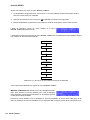
-30dB…LIMIT
Level indication is realized via two vertical LED chains on the power amp’s front panel that individually
indicate the actual levels of each channel at -30dB, -20dB, -10dB below full modulation and 0dB as soon
as full modulation is reached. 0 dB indication results from comparing the power amp’s internal ratio of input
to output voltage, which ensures precise indication of the full modulation limit, even before limiting
becomes audible. If the input audio signal is driven above the 0 dB mark, a clipping limiter reliably controls
distortion down to a stable rate of 1 %. The red LIMIT-LED has a dynamic brightness control that makes it
easy to perceive the degree of limiting applied to the signal.
POWER
The POWER-LED lights green when the power amplifier is on. If the POWER-LED does not light, despite
the fact that the amplifier has been switched on, this indicates that the power amp is not connected to the
mains, the primary fuse has blown, or the amplifier is in standby mode (the STANDBY-LED lights yellow).
The POWER-LED blinks whenever the voltage at the MAINS IN is too high (overvoltage) or too low
(undervoltage), which prevents that the power amplifier can be switched on.
STANDBY
The STANDBY-LED lights yellow when the power amp is in standby mode. Standby mode reduces the
amp’s power consumption to an absolute minimum. Activating the standby mode is only possible via IRISNet. Deactivating the standby mode is possible via IRIS-Net as well as directly on the power amplifier. For
deactivating the standby mode, select Power from the Module Config menu (see page 29).
30
Owner’s Manual
PowerH SERIES
IRIS-Net
The IRIS-Net-LED lights blue if an IRIS-Net-compatible remote control module has been installed in the
power amp’s extension slot and successful data communication has been established. All LEDs blink
slowly whenever the “Find” function in IRIS-Net is being used to locate a power amplifier in the rack.
Deactivate „Find“ function via IRIS-Net or press any key at the amplifier front.
3.4 Fan Cooling
The power amplifier has two fans on the front and one on the rear. The fans are switched in five
performance-optimized levels, i.e. they are not running permanently but the running speed of each fan is
individually controlled depending on the ambient temperature. That in return ensures very silent running
during idle state. The temperatures of the power amp’s two channels and of the power supply unit are
registered and monitored separately. The intelligent and processor-controlled fan-control activates a fan to
run exactly at the level that is needed to cool down the corresponding components. This concept
effectively prevents the needless "rev up" of the fans when in idling state as well as the occurrence of a
thermally balanced condition, which causes permanent noise-intensive running of the fans. In other words,
the fans are activated only when it is really necessary because of thermal conditions. During power-on of
the amplifier, all fans run for a short period of time to verify the correct functioning.
3.5 Protections
In case one of the power amp’s internal protections responds during operation, a corresponding message
appears on the LC display (or the PROTECT-LED lights) and an entry containing date, time, and protection
type is created in the event log.
True RMS Mains Voltage and Current Measurement
PowerH SERIES amplifiers are consistently informed about the state of the mains network that they are
connected to. The CPU of the power amplifier continually computes the current RMS (Root Mean Square,
effective value) of the mains voltage and the mains current consumption. This genuine RMS measurement
has substantial advantages over the commonly used peak value measurement:
•
Mains voltage measurement functions reliably even with non-sinusoidal mains networks, which, for
example, can be found with a generator-powered amplifier or when the mains voltage situation becomes unstable.
•
Mains voltage measurement is insusceptible to transient mains interference, as can occur when switching inductive loads such as large electric motors.
•
True mains current RMS measurement allows the precise matching of the power consumption to the
characteristics of a mains circuit breaker. Detailed information about the adjustable Mains Circuit Breaker Protection function is provided in the following paragraph.
RMS measurement permanently protects the power amplifier against mains over or undervoltage. At the
occurrence of extreme mains overvoltage, the power amp switches off to prevent severe damage.
Switching on the power amp is not possible whenever mains overvoltage has been detected. The mains
voltage monitoring protection switches the power amplifier off at the occurrence of extreme mains
undervoltage (less than 70 V AC). In both cases, the blinking POWER-LED indicates the fault condition. In
Owner’s Manual
31
PowerH SERIES
case of power outage, both output channels are instantly muted then the power amplifier is shut down
within only a few milliseconds.
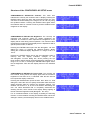
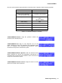
Mains Circuit Breaker Protection
The power amplifier automatically reduces the output power whenever it is driven at high levels with
extremely low-impedance loads connected resulting in the chance that the mains circuit breaker reacts.
Therefore, adjusting the characteristics of the utilized circuit breaker in Amperes is possible via the LC
display. Especially at extremely high/low ambient temperatures or when connecting the power amplifier
together with other equipment to a single common automatic circuit breaker, it might become necessary to
manually set an Ampere value that differs from the circuit breaker’s nominal value to ensure that the Mains
Circuit Breaker Protection functions optimally. The following table outlines the allowable value ranges and
default settings for the two modes of operation at 120 V and 220-240 V.
Operation
Minimum
Maximum
Factory Settings
120 V
6A
40 A
30 A
220-240 V
6A
30 A
16 A
Table 3.4: Mains Circuit Breaker Protection
The power amp’s CPU is acquainted with the temporal progression of the mains current consumption and
therefore can simulate the typical behavior of a mains circuit breaker. Nevertheless, pulse peaks allow
crest currents that can exceed the nominal value by a multiple. RMS measurement of the mains current
consumption allows the CPU to emulate the temperature curve of a circuit breaker’s thermal trip, which in
return enables the Mains Circuit Breaker Protection to let the power amplifier work till shortly below the
trigger level of the automatic circuit breaker. With typical concepts, especially for those without RMS
current measurement, output power reduction has to be applied much earlier. During the processing of
musical program material, the Mains Circuit Breaker Protection normally does not have to reduce the
power amp’s output power. At most, with settings that are noticeably below the pre-set values of 16 A or 30
A respectively, (which may be reasonable when operating multiple power amps via a single automatic
circuit breaker) output power reduction might become necessary to prevent the mains fuse from blowing.
Power-On Delay and Softstart
A Power-On Delay of up to 6.35 seconds can be programmed for the power amp via the LC display. Upon
pressing the mains switch the power amplifier does not start until the set delay time has elapsed. If several
power amps are operated on the same automatic circuit breaker, cascaded switch-on can be accomplish
by programming individually different power-on delays for the amps. This also prevents the magnetic trip of
an automatic circuit breaker from acting and thus disconnecting the power amplifiers from the mains
supply, when various amps are switched on at the same time. The internal soft-start function additionally
suppresses current peaks during power-on, which ensures trouble-free operation of PowerH SERIES
amplifiers even on very sensitive automatic circuit breakers.
32
Owner’s Manual
PowerH SERIES
Output Short Circuit Detection
The corresponding output voltage and output current is measured for both output channels as soon as the
power amplifier processes an audio signal. These readings are used to monitor the connected
loudspeaker loads. The power amplifier has the ability to continuously deliver very high output currents.
For example, if, in spite of a low output voltage, the current flow is high as the consequence of a shortcircuit in one of the speaker lines, the power amp detects this fault condition and immediately disables
signal output to protect connectors and cables against damage from overload. This, of course, also
protects the power amplifier itself from being damaged by excessive electrical or thermal overload.
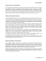
Advanced Thermal Protection
The PowerH SERIES amplifiers are the first to feature the new Advanced Thermal Protection (ATP). This
new system differs in a trend-setting manner from traditional thermal protection measures, which, as soon
as the fans are not any longer capable of dissipating the lost heat, mostly switch off the entire signal path at
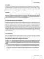
a relative early stage. With the ATP system switching off the signal path is last of three consecutive
measures. Prior to making this final step, the system uses two other approaches to limit the amp’s power,
so that it returns to a thermally stable operational range.
The first step is Voltage Limitation. This measure reduces the internal supply voltage of the power amplifier
blocks, which, objectively, is at the expense of reducing the voltage dynamic. During the reproduction of
music or speech, however, this effect is subjectively hardly perceived. Despite the negligible acoustic
influence, the efficiency gained in the power amp is so high that the development of heat is clearly
reduced. As soon as the power amp’s temperature returns to a non-critical state, the ATP system
imperceptibly switches back to full supply voltage.
Thermal Limiter is the second measure that is only activated if, under extreme conditions, Voltage
Limitation is not sufficient. The thermal limiter circuit unobtrusively reduces the amplification of the power
amplifier. Only if even this measure does not re-establish thermal balance, the ATP system activates
Thermal Mute as the last step to completely switch off the signal path.
This step-by-step functioning of Advanced Thermal Protection enables PowerH SERIES amplifiers to still
be in operation under conditions where various other amps would have ceased operation.
The PROTECT-LED lights immediately to signal a direct intervention in the signal path by limiters and a
corresponding indicator in IRIS-Net allows the FOH-engineer to react instantly, even before interference
with the audio performance becomes noticeable.
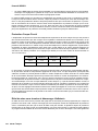
Monitoring Ambient Temperature
PowerH SERIES amplifiers constantly monitor the temperature of several active electrical components
during operation. In addition, monitoring also includes the temperature of the inlet cooling air and as a
result also the temperature of the power amp’s ambience. If, for any reason the ventilation louvers are
totally blocked or the inlet outer air exceeds the upper temperature limit for effective cooling, this would
inevitably lead to overheating of the power amplifier. This condition can possibly occur even when the
power amplifier is in idling mode, for example when it is installed in a closed rack case.
However, during idling the preventive measures of the Advanced Thermal Protection (see previous
paragraph) show hardly any impact. For this reason the power amplifier enters standby mode once it is
operated under extreme thermal load, which is caused by inadequate cooling. In that case, PROTECTLED and STANDBY-LED blink alternately.
Owner’s Manual
33
PowerH SERIES
The power amplifier automatically re-starts after approximately 20 minutes. As an alternative, re-starting
the power amplifier manually using the mains switch or via IRIS-Net is also possible, if the device has
cooled down sufficiently.
HF-Limiter
If the power amplifier processes high-frequency signals at high levels, amplification is automatically
reduced after a while to protect the output stages against damage. Most of the time such conditions result
from a malfunction in one of the devices that are connected upstream in the signal chain. The situation
becomes particularly critical for power amplifier and connected tweeter cabinets when the signal is still in
the audible range or just above the auditory threshold. Conventional HF-Protection circuits are not
sensitive enough to react within this particular range, since they are primarily targeted at detecting fault
conditions of the power amplifier itself.
Next to conventional HF-Protection, PowerH SERIES amplifiers have also a HF-Limiter, which is
frequency-dependent and permanently monitors the output signal. The HF-Limiter possesses the ability to
reliably differentiate between normal reproduction of music and speech and critical operating conditions.
The power amp’s signal amplification is automatically reduced whenever such a critical operating condition
occurs.
34
Owner’s Manual
PowerH SERIES
4 Options
Installing one of the optionally available extension modules in the extension slot on the rear panel lets you
expand the power amp’s functional range. As an example, the following paragraphs describe all aspects of
the RCM-26 Remote Control Module in detail. Please read and follow the instructions provided in the
owner’s manuals that you have received together with each extension module.
4.1 RCM-26
System Description
The RCM-26 Remote Control Module is a two-channel digital controller module for live sound
reinforcement, PA and fixed installation applications. Installing the RCM-26 turns a conventional amp into a
remote amplifier, which, at any time, provides complete overview of the overall system status and control
of all system parameters.
RCM-26 modules allow the integration of PowerH amplifiers into a remote control network with up to 250
units. This offers the possibility to control and monitor an entire PA system from one or more PCs using the
IRIS-Net - Intelligent Remote & Integrated Supervision - software package. All operational states, e.g.
power-on status, temperature, modulation, limiting, activation of protections, deviation from the load
impedance, etc., are centrally registered and displayed in IRIS-Net. This provides the possibility to react
and to selectively intervene even before critical operational states arise. Programming an automatic
reaction, when specific thresholds are being exceeded or fallen below, is also possible.
With an RCM-26 installed, the integrated impedance testing function allows very precise monitoring of the
connected loudspeaker systems. The impedance testing function utilizes the internal test tone signal
generator and voltage/current measuring to determine the impedance of the loudspeaker systems
including crossovers and cables over the entire frequency range. IRIS-Net plots an impedance curve of the
measured impedance that can be compared with a formerly stored reference curve at any time. This
reveals even smallest loudspeaker defects or deficiencies instantly. The impedance testing function is
optimized for low impedance loads, like typical loudspeaker cabinets and/or loudspeaker components.
All parameters, like power on/off, level, muting, filters, etc. can be controlled in real-time and stored in the
amplifier. Besides controlling and monitoring amplifiers, the RCM-26 also offers all conventional signal
processing functions, like parametric equalizers, frequency crossovers, delays, compressors and limiters.
Beyond that, linear-phase FIR-filters, zero-latency FIR-filters and digital speaker protection algorithms are
available to optimize the amplifier and loudspeaker system. All DSP-settings can be freely edited and
stored in user presets directly on the module. In the event of network failure or loss of power, all settings
(filters, delay, level, etc.) stay intact, independent of the control by the network.
Furthermore, the RCM-26 provides a control port with freely programmable control inputs and control
outputs. Control inputs (GPI's) allow the connection of switches. IRIS-Net offers the possibility to program
a variety of logic functions for the inputs (e.g. switching to an alarm-preset with maximum energy in the
speech area). Control outputs (GPO's) allow the connection of external components, which, for example,
are used to signal specific states to peripheral equipment. Consequently, an amplifier with a RCM-26
module installed corresponds to highest safety requirements.
The RCM-26 has been designed with uncompromising audio quality in mind. Analog audio inputs
(internally) and an AES3 (AES/EBU) digital audio input with XLR-type connector are provided. The use of
Owner’s Manual
35
PowerH SERIES
the digital audio input offers a dynamic range of 128 dB. Using the analog audio input offers a dynamic
range of 120 dB, which, by the way, is an absolute peak value for digital audio devices.
For further details about configuration, control and monitoring of amps with installed RCM-26 modules,
please refer to the documentation of the IRIS-Net software.
Installation Notes
Installation
1. Switch the power amp’s power off and pull the mains plug
2. Remove the cover panel from the rear panel (4 screws)
3. Insert the RCM-26 module in the slot and lock it in place on the rear panel using the 4 screws (see
illustration 4.1)
Illustration 4.1: Installation of a RCM-26
4. Set the module’s CAN-address using the ADDRESS selector switches
5. Connect the needed interfaces (CAN, Audio, Control Port, RS-232)
6. Reconnect the mains cord and switch on the power amplifier
7. The power amp automatically recognizes the installed RCM-26 module
Conversion from Pre Fader Mode to Post Fader Mode
The RCM-26 is shipped from the factory in the recommended "Pre Fader" mode, so the input level
controllers on the front of the amplifier are taken out of operation by installation of the RCM-26. If the input
level controller are to be usable with a RCM-26 installed, the RCM-26 must be converted to "Post Fader"
mode.
The conversion is done by changing the jumper settings of jumper JP1 to JP5 on the RCM-26. The
following pictures show the jumper settings for "Pre Fader" mode and "Post Fader" mode. Only the jumper
settings shown are allowed.
36
Owner’s Manual
PowerH SERIES
Illustration 4.2: Pre Fader mode (left) and Post Fader mode (right)
IRIS-Net
Configuring and controlling a remote amplifier
with a RCM-26 module installed is possible
through the use of IRIS-Net (Intelligent Remote
& Integrated Supervision) PC-software. IRISNet allows programming the RCM-26 module’s
complete configuration while the computer is
off-line. All instructions on how to configure,
operate and monitor all RCM-26 functions are
included in the IRIS-Net help files.
Illustration 4.3: DSP flow diagram of the RCM-26
Owner’s Manual
37
PowerH SERIES
Controls and Connections
Illustration 4.4: Controls and Connections of the RCM-26
1 AES/EBU-IN
A digital AES/EBU input (AES3) is provided in addition to
internal analog inputs. The digital input signal has to be
connected to the AES/EBU IN connector. The AES/EBU
input is a balanced transformer-isolated input. A sampling
rate converter translates the input signal to match the
internal sampling rate. However, the possibility to
synchronize the RCM-26 to an external sampling rate exists
as well. For further details, please refer to the IRIS-Net help
files. Illustration 4.5 shows the pin-assignment of the input
socket.
Illustration 4.5: Pin-assignment
of AES/EBU-IN
2 AES/EBU-OUT
The AES/EBU OUT connector allows looping-through the
digital audio signal to other RCM-26 modules. The digital
input signal gets internally buffered and preprocessed (level
matching / slew rate) before it is output via the OUTconnector. This allows fairly simple wiring between
modules, without the need for AES/EBU distribution amps
as they are usually used.
The RCM-26 has a bypass-relay, which, in case of damage
(e.g. power outage), connects the AES/EBU IN signal
through to AES/EBU OUT. This ensures trouble-free
operation of downstream remote amps.
38
Owner’s Manual
Illustration 4.6: Pin assignment
of AES/EBU-OUT
PowerH SERIES
3 LOCK-LED
The LOCK-LED lights green as soon as the AES/EBU input has been synchronized to the
incoming signal and thus proper audio transmission has been established. The LOCK-LED is
dimmed with no digital audio signal being present at the input or the internal PLL not having
locked on to the incoming signal. The audio signal gets muted when the digital input has been selected.
4 REMOTE CAN BUS Connection
The RCM-26 module provides two Neutrik etherCON RJ-45 sockets for connecting to the REMOTE CAN
BUS. These sockets are connected in parallel and serve as input as well as for daisy-chaining the devices
on the remote network. Cabling in a rack system can be established using commercially available RJ-45
network cables. However, CAN guidelines have to be observed for longer cable lengths. Both ends of the
CAN-bus must be terminated using 120 terminating plugs. For comprehensive information and
instructions on cabling and bus length, please refer to the “CAN Bus principles“ paragraph, starting on
page 42. Along with the CAN bus, network cabling also carries a balanced audio monitoring signal. This
monitor bus allows software-controlled monitoring of input or output signals of all power amps in the
remote network, without the need for additional wiring. Nominal output level is +6 dBu (1.55 V) and
maximum output level is +21 dBu (8.7 V).
The CAN bus allows using different data rates, whereas the data rate is inversely proportional to the bus
length. For smaller network setups, data rates can be as high as 500 kbit/s. For broader networks,
reducing the data rate becomes necessary (down to the minimum data rate of 10 kbit/s).
NOTE:
The data rate of the CAN Bus is preset to 10 kbit/s.
The following table illustrates the relation between data rate and bus length or network size. The use of
CAN repeaters is strongly recommended for busses that exceed 1000 meters in length.
Transfer rate (in kbit/s)
Bus length (in m)
500
100
250
250
125
500
62,5
1000
20
2500
10
5000
Table 4.1: Transfer rate and bus length
Illustration 4.7: Pin-assignment of CAN jack
Owner’s Manual
39
PowerH SERIES
Illustration 4.8: Pin-assignment of CAN plug
Colour
Pin
Name
2
CAN_GND
4
CAN_H (+)
Blue
5
CAN_L (-)
Blue striped
7
MONITOR BUS +
Brown striped
8
MONITOR BUS -
Brown
T568A
T568B
Green
Orange
Table 4.2: Overview CAN plug
5 STATUS LED
The STATUS-LED is for monitoring the communication on the CAN bus. The LED blinks
rhythmically every 3 seconds, when the module’s address is set to “00“, which means that it
is disconnected from the CAN bus and software control. The LED blinks rhythmically in
intervals of one second, when an address in the range of 01 to 250 has been assigned to the
module and there has not yet been any activity on the CAN bus. As soon as communication
on the CAN bus is recognized, the LED lights for at least 100 ms, when the power amplifier
sends data on the CAN bus.
6 ADDRESS Selector Switch
The two address selector switches are for setting the network address of the RCM-26.
CAN networks support addresses in the range of 01 to 250 (FA hex). Addressing has to
be carried out in the hexadecimal number system. The LOW selector switch sets the
lower digit, while HIGH sets the higher digit.
CAUTION:
Each address may exist only onece in a system. Otherwise, network conflicts may arise
Address 0 (00 hex, delivery status) disables remote communication between the RCM-26 and the bus. The
module does not appear in the system, even though it is physically connected to the CAN-bus. Switching
on the power of an amplifier with an installed RCM-26 that has been assigned address 0 sets all its internal
parameters to 0 or bypass and the signal routing to 2-in-2. The power amplifier behaves absolutely linear,
i.e. signal processing is deactivated.
40
Owner’s Manual
PowerH SERIES
HIGH
LOW
Address
0
0
Stand-alone
0
1...F
1...15
1
0...F
16...31
2
0...F
32...47
3
0...F
48...63
4
0...F
64...79
5
0...F
80...95
6
0...F
96...111
7
0...F
112...127
8
0...F
128...143
9
0...F
144...159
A
0...F
160...175
B
0...F
176...191
C
0...F
192...207
D
0...F
208...223
E
0...F
224...239
F
0...A
240...250
F
B...F
reserved
Table 4.3: CAN addresses
7 CONTROL PORT
The CONTROL PORT of the RCM-26 provides two control inputs, two control
outputs and reference connections for +5V and ground. The control inputs are
configurable via IRIS-Net. They can be used for example for switching between
power on / standby modes, switching between presets or to control parameters.
The two control contacts IN1 and IN2 are internally connected via pull-up
resistors and carry +5V (open). The control inputs can be activated using
external switches, pushbuttons or relays to connect them to ground potential (pin 3). The two control
outputs OUT1 and OUT2 are open collector outputs, which are highly resistive in the non-active state (off).
In active state (on) the outputs are connected to ground. The control outputs are configurable via IRIS-Net
and are used to signal internal states. LEDs, indicators or relays can be driven directly. The +5V reference
connector provides voltage supply for connected components.
CAUTION:
The maximally allowable current at the +5V output is 200 mA.
8 RS-232 Interface
The RS-232 interface is for interconnecting the RCM-26 module and multi-media control systems or facility
management systems. All parameters can be controlled and queried via RS-232 interface. Communication
is realized through the use of ASCII-protocol. Implementation of this protocol is rather simple.
Programming notes and a complete protocol description are included in the IRIS-Net documentation. The
Owner’s Manual
41
PowerH SERIES
following illustration shows the pins of the RS-232 interface that the RCM-26 uses. The length of the RS232 cable that is employed to connect the RCM-26 to another device should not exceed 15 meters.
Illustration 4.9: Pin-assignment of RS-232 Interface
The following table shows the factory-fixed settings of the RCM-26’s RS-232 interface. The connected
device (e.g. a PC with terminal program, multi-media control software) needs to be identically configured
for data transfer to work properly.
Parameter
Value
Data bit
8
Parity bit
-
Stop bit
1
Transfer rate
19200 bit/s
Table 4.4: Parameter of RS-232 Interface
CAN Bus Principles
The network topology used by the CAN bus is based on the so-called “bus or line topology”, i.e. all
participants are connected via a single two-wire cable (Twisted-Pair cable, shielded or unshielded) with the
cabling running from one participant on the bus to the next, allowing unlimited communication among all
devices. In general, it does not matter if the bus member is a RCM-26, a USB-CAN converter or another
device. Thus, the RCM-26 can be connected at any place of the CAN bus. In total, up to 100 devices can
be connected to one CAN bus.
The CAN bus has to be terminated with a 120 terminating resistor at both ends. If the termination is
missing or an improper resistor value is used, network errors can occur as a signal is reflected on the bus
at both bus ends. Because of the superposition of the reflection with the original signal, the original signal
is blurred. This may result in the loss of data. In order to prevent or minimize reflections at the bus ends,
terminators are used as they "absorb" the energy of the signal.
Since the CAN interfaces of all EVI Audio appliances are galvanically separated from the rest of the
circuitry, network cabling also carries a common ground conductor (CAN_GND) ensuring that all CANinterfaces in the network are connected to a common ground potential.
42
Owner’s Manual
PowerH SERIES
Illustration 4.10: Bus Topology of the CAN bus
By using a CAN bus repeater a connection between two independent and self-contained CAN bus systems
can be created. Thus, the following can be achieved:
•
Increase of the max. number of members
A maximum of 100 devices can be connected to one CAN bus. This number can be increased up to
250 by connecting several CAN bus systems. This limitation of exactly 250 devices results from the
addressing scheme used by the CAN bus. The addressing scheme allows the allocation of a maximum
of 250 different CAN device addresses.
•
Improvement of signal quality
With CAN bus systems, whose bus length exceeds 1000 meters, a CAN bus repeater should be used.
The CAN bus repeater accomplishes a signal processing and a reinforcement of the bus signals. The
internal running time of the repeaters of approx. 150 ns corresponds to an extension of the bus over
approx. 45 meters.
•
Creation of alternative network topologies
By using one or several repeaters, not only the above-mentioned bus topology, but the creation of
other network topologies are also possible.
Owner’s Manual
43
PowerH SERIES
System Examples
The following illustrations show examples of the data-bus wiring for different sizes of CAN-bus networks.
Illustration 4.11: System with 5 power amps (with RCM-26) and 1 USB-CAN-Converter. Termination plugs
at the USB-CAN-Converter and the RCM-26 of amp 5
Illustration 4.12: System with 2 amp-racks and 1 USB-CAN-Converter. Termination plugs at amp 6 (first unit
on the bus) and amp 12 (last unit on the bus)
44
Owner’s Manual
PowerH SERIES
Performance Specifications
According to the ISO 11898-2 standard, CAN-bus data transfer cabling has to be carried out using TwistedPair cables with or without shielding providing a characteristic impedance of 120 . Both ends of a CANbus need to be terminated with 120 termination-plugs. The maximum bus-length depends on the actual
data transfer rate, the kind of data transfer cable being used, as well as the total number of participants on
the bus. The following table shows the most essential requirements for CAN-networks consisting of up to
64 participants.
Data Transmission Cable
Bus Length Resistance per Unit
(in m)
Length
Cable Diameter
(in m/m)
Termination (in )
Max. Data Transfer Rate
0...40
< 70
0,25...0,34 mm²
AWG23, AWG22
124
1000 kbit/s
at 40 m
40...300
< 60
0,34...0,6 mm²
AWG22, AWG20
127
500 kbit/s
at 100 m
300...600
< 40
0,5...0,6 mm²
AWG 20
150...300*
100 kbit/s
at 500 m
600...1000
< 26
0,75...0,8 mm²
AWG 18
150...300*
62,5 kbit/s
at 1000 m
* With longer cables and many participants on the CAN-bus, termination resistors with higher impedance
than the specified 120 are recommended to reduce the ohmic load of the interface drivers and therefore
the voltage drop between the two cable-ends.
The following table is meant for first assessment of necessary cable diameters for different bus lengths and
bus-participant numbers.
Bus Length (in m)
Number of Units on the CAN-Bus
32
64
100
100
0,25 mm² / AWG24
0,34 mm² / AWG22
0,34 mm² / AWG22
250
0,34 mm² / AWG22
0,5 mm² / AWG20
0,5 mm² / AWG20
500
0,75 mm² / AWG18
0,75 mm² / AWG18
1,0 mm² / AWG17
Additionally, the length of branch lines - for participants that are not directly connected to the CAN-bus - is
also of importance. For data transfer rates of up to 125 kbit/s, the maximum length of a single stub cable
should not exceed 2 meters. For higher bit rates a maximum length of only 0.3 meter is still permissible.
The entire length of all branch lines should not exceed 30 meters.
General Note:
•
As long as only short distances (up to 10 meters) are concerned, common RJ-45 patch cables with a
characteristic impedance of 100 (AWG 24 / AWG 26) can be used for the cabling inside of a rack
mounted system.
•
The previously outlined guidelines for network cabling are mandatory as far as the rack mounted
shelve interconnection or fixed installations are involved.
Owner’s Manual
45
PowerH SERIES
46
Owner’s Manual
PowerH SERIES
WICHTIGE SICHERHEITSHINWEISE
Das Blitzsymbol innerhalb eines gleichseitigen
Dreiecks soll den Anwender auf nicht isolierte Leitungen und Kontakte im Geräteinneren hinweisen,
an denen hohe Spannungen anliegen, die im Fall
einer Berührung zu lebensgefährlichen Stromschlägen führen können.
Das Ausrufezeichen innerhalb eines gleichseitigen
Dreiecks soll den Anwender auf wichtige Bedienungs- sowie Servicehinweise in der zum Gerät
gehörenden Literatur aufmerksam machen.
1.
2.
3.
4.
5.
6.
7.
8.
9.
10.
11.
12.
13.
14.
15.
16.
17.
18.
19.
Lesen Sie diese Hinweise.
Heben Sie diese Hinweise auf.
Beachten Sie alle Warnungen.
Richten Sie sich nach den Anweisungen.
Betreiben Sie das Gerät nicht in unmittelbarer Nähe von Wasser.
Verwenden Sie zum Reinigen des Gerätes ausschließlich ein trockenes Tuch.
Verdecken Sie keine Lüftungsschlitze. Beachten Sie bei der Installation des Gerätes stets die entsprechenden Hinweise des Herstellers.
Vermeiden Sie die Installation des Gerätes in der Nähe von Heizkörpern, Wärmespeichern, Öfen oder anderer Wärmequellen.
Achtung: Gerät nur an Netzsteckdose mit Schutzleiteranschluss betreiben. Setzen Sie die Funktion des Schutzleiteranschlusses des
mitgelieferten Netzanschlusskabels nicht außer Kraft. Sollte der Stecker des mitgelieferten Kabels nicht in Ihre Netzsteckdose passen,
setzen Sie sich mit Ihrem Elektriker in Verbindung.
Sorgen Sie dafür, dass das Netzkabel nicht betreten wird. Schützen Sie das Netzkabel vor Quetschungen insbesondere am Gerätestecker
und am Netzstecker.
Verwenden Sie mit dem Gerät ausschließlich Zubehör/Erweiterungen, die vom Hersteller hierzu vorgesehen sind.
Verwenden Sie zusammen mit dieser Komponente nur vom Hersteller dazu vorgesehene oder andere geeignete Lastkarren,
Stative, Befestigungsklammern oder Tische, die Sie zusammen mit dem Gerät erworben haben. Achten Sie beim Transport
mittels Lastkarren darauf, dass das transportierte Equipment und der Karren nicht umfallen und möglicherweise Personenund/oder Sachschäden verursachen können.
Ziehen Sie bei Blitzschlaggefahr oder bei längerem Nichtgebrauch den Netzstecker.
Überlassen Sie sämtliche Servicearbeiten und Reparaturen einem ausgebildeten Kundendiensttechniker. Servicearbeiten
sind notwendig, sobald das Gerät auf irgendeine Weise beschädigt wurde, wie z.B. eine Beschädigung des Netzkabels oder des
Netzsteckers, wenn eine Flüssigkeit in das Gerät geschüttet wurde oder ein Gegenstand in das Gerät gefallen ist, wenn das Gerät Regen
oder Feuchtigkeit ausgesetzt wurde, oder wenn es nicht normal arbeitet oder fallengelassen wurde.
Stellen Sie bitte sicher, dass kein Tropf- oder Spritzwasser ins Geräteinnere eindringen kann. Platzieren Sie keine mit Flüssigkeiten
gefüllten Objekte, wie Vasen oder Trinkgefäße, auf dem Gerät.
Um das Gerät komplett spannungsfrei zu schalten, muss der Netzstecker gezogen werden.
Beim Einbau des Gerätes ist zu beachten, dass der Netzstecker leicht zugänglich bleibt.
Stellen Sie keine offenen Brandquellen, wie z.B. brennende Kerzen auf das Gerät.
Dieses SCHUTZKLASSE I Gerät muss an eine NETZ-Steckdose mit Schutzleiter-Anschluss angeschlossen werden.
WICHTIGE SERVICEHINWEISE
ACHTUNG: Diese Servicehinweise sind ausschließlich zur Verwendung durch qualifiziertes Servicepersonal. Um die
Gefahr eines elektrischen Schlages zu vermeiden, führen Sie keine Wartungsarbeiten durch, die nicht in der
Bedienungsanleitung beschrieben sind, außer Sie sind hierfür qualifiziert. Überlassen Sie sämtliche
Servicearbeiten und Reparaturen einem ausgebildeten Kundendiensttechniker.
1.
2.
3.
4.
5.
6.
7.
8.
9.
Bei Reparaturarbeiten im Gerät sind die Sicherheitsbestimmungen nach EN 60065 (VDE 0860) einzuhalten.
Bei allen Arbeiten, bei denen das geöffnete Gerät mit Netzspannung verbunden ist und betrieben wird, ist ein Netz-Trenntransformator zu
verwenden.
Vor einem Umbau mit Nachrüstsätzen, Umschaltung der Netzspannung oder sonstigen Modifikationen ist das Gerät stromlos zu schalten.
Die Mindestabstände zwischen netzspannungsführenden Teilen und berührbaren Metallteilen (Metallgehäuse) bzw. zwischen den
Netzpolen betragen 3 mm und sind unbedingt einzuhalten.
Die Mindestabstände zwischen netzspannungsführenden Teilen und Schaltungsteilen, die nicht mit dem Netz verbunden sind (sekundär),
betragen 6 mm und sind unbedingt einzuhalten.
Spezielle Bauteile, die im Stromlaufplan mit dem Sicherheitssymbol gekennzeichnet sind, (Note) dürfen nur durch Originalteile ersetzt
werden.
Eigenmächtige Schaltungsänderungen dürfen nicht vorgenommen werden.
Die am Reparaturort gültigen Schutzbestimmungen der Berufsgenossenschaften sind einzuhalten. Hierzu gehört auch die Beschaffenheit
des Arbeitsplatzes.
Die Vorschriften im Umgang mit MOS-Bauteilen sind zu beachten.
NOTE:
SAFETY COMPONENT (MUST BE REPLACED BY ORIGINAL PART)
Hinweise zur Entsorgung/Wiederverwendung gemäß WEEE
Das auf unserem Produkt und im Handbuch abgedruckte Mülltonnensymbol weist daraufhin, dass dieses Produkt nicht gemeinsam mit dem Haushaltsmüll entsorgt werden
darf. Für die korrekte Entsorgung der Elektro- und Elektronik-Altgeräte (WEEE) am Ende ihrer Nutzungsdauer ist in unserer Kategorie der Hersteller verantwortlich. Aufgrund
unterschiedlicher Regelungen zur WEEE-Umsetzung in den einzelnen EU-Staaten bitten wir Sie, sich an Ihren örtlichen Händler zu wenden. Wir haben ein eigenes System zur
Verarbeitung elektronischer Abfälle und gewährleisten die kostenfreie Entgegennahme aller Produkte der EVI Audio GmbH: Telex, Dynacord, ElectroVoice, Midas Consoles,
KlarkTeknik und RTS. Wir haben mit dem Händler, bei dem Sie Ihr Produkt gekauft haben, eine Vereinbarung getroffen, dass alle nicht mehr verwendbaren Geräte zur
umweltgerechten Entsorgung kostenfrei an das Werk in Straubing zurückgeschickt werden.
Due to line current harmonics, we recommend that you contact your supply authority before connection.
Bedienungsanleitung
47
PowerH SERIES
1 Einführung
1.1 Willkommen
Mit den neuen Endstufen der PowerH SERIES von Dynacord beginnt ein neues Zeitalter in der EndstufenTechnologie. Die hocheffiziente PowerH-Endstufe liefert kompromisslose Audioperformance bei geringem
Gewicht und höchster Zuverlässigkeit. Durch optionale Remote-Control-Module ist die vollständige
Kontrolle und Überwachung der Endstufe über die PC Software IRIS-Net möglich.
1.2 Auspacken und Inspektion
Öffnen Sie die Verpackung und entnehmen Sie die Endstufe. Überprüfen Sie die Endstufe auf äußere
Beschädigungen, die während des Transports zu Ihnen aufgetreten sein können. Jede Endstufe wird vor
Verlassen des Werks eingehend untersucht und getestet und sollte in einwandfreiem Zustand bei Ihnen
ankommen. Falls die Endstufe Beschädigungen aufweist, benachrichtigen Sie bitte unverzüglich das
Transportunternehmen. Ein Transportschaden kann nur von Ihnen, dem Empfänger, reklamiert werden.
Bewahren Sie den Karton und das Verpackungsmaterial zwecks Besichtigung durch das
Transportunternehmen auf.
Die Aufbewahrung des Kartons samt Verpackungsmaterial wird auch dann angeraten, wenn die Endstufe
keine Beschädigung aufweist.
ACHTUNG:
Versenden Sie die Endstufe nie ohne das original Verpackungsmaterial.
Wenn Sie die Endstufe verschicken, verwenden Sie stets den Originalkarton und das original
Verpackungsmaterial. Für bestmöglichen Schutz vor Transportschäden verpacken Sie die Endstufe wie
sie ursprünglich im Werk verpackt wurde.
1.3 Lieferumfang und Garantie
•
1 Endstufe H2500/H5000
•
1 Handbuch (dieses Dokument)
•
2 Phoenix-Stecker
•
1 Netzkabel
•
2 Befestigungwinkel für Rackeinbau
•
4 Käfigmuttern + Schrauben
•
4 Standfüße
•
1 Garantiekarte
Bewahren Sie zur Garantiekarte auch den Kaufbeleg, der den Termin der Übergabe festlegt, auf. Das
Werk leistet Garantie für alle nachweisbaren Material und Fertigungsfehler für die Dauer von 36 Monaten
ab Verkauf. Garantieleistungen werden nur dann anerkannt, wenn gültige, d.h. vollständig ausgefüllte
Garantieunterlagen vorliegen. Von der Garantie ausgenommen sind alle Schäden, die durch falsche oder
unsachgemäße Bedienung verursacht werden. Bei Fremdeingriffen oder eigenmächtigen Änderungen
erlischt jeder Garantieanspruch.
48
Bedienungsanleitung
PowerH SERIES
1.4 Eigenschaften & Beschreibung
Die Endstufe H2500/H5000 gehört zur neuen PowerH SERIES von Dynacord, die einen Meilenstein in
Design und Produktion von Hochleistungs-Endstufen darstellt. Die innovative 3-stufige Grounded Bridge
Class H Topologie mit „Floating“ Schaltnetzteil bietet eine sehr hohe, stabile Ausgangsleistung bei sehr
hohem Wirkungsgrad auf extrem hohem Performance-Niveau und dabei äußerst geringem Gewicht. Die
PowerH-Endstufen sind damit der ideale Antrieb für professionelles Touring, High-End Concert-Sound
sowie Pro-Sound Applikationen.
Neben den klassischen Schutzschaltungen kommt erstmals das mehrstufige ATP-System (Advanced
Thermal Protection) zum Einsatz. Durch dieses System kann in den meisten Fällen ein Abschalten der
Endstufe bei Übertemperatur verhindert werden. Ein Ausfall der Endstufe durch das Auslösen des zur
Absicherung der Endstufe verwendeten Sicherungsautomaten wird durch das neuartige MCS-System
(Mains Current Supervision) verhindert. Hierzu wird unter anderem eine hochpräzise Messung des RMSWertes des aufgenommenen Netzstromes durchgeführt.
Informationen über den Status der Endstufe und der integrierten Schutzschaltungen werden über ein LCDisplay angezeigt. Durch den optionalen Einsatz eines IRIS-Net kompatiblen Remote-Control-Moduls
bietet die Endstufe zudem umfangreiche Fernüberwachungs- und Steuerungsfunktionen, sowie einen
universellen 2-kanaligen digitalen Audio-Controller (DSP) einschließlich hochgenauer FIR-Filterung und
digitaler Algorithmen zum Lautsprecherschutz.
1.5 Verantwortung des Betreibers
Beschädigung von Lautsprechern
Die PowerH-Endstufe verfügt über eine sehr hohe Ausgangsleistung und kann sowohl für Menschen als
auch für angeschlossene Lautsprecher eine Gefahr darstellen. Lautsprecher können durch zu hohe
Leistung beschädigt oder zerstört werden, vor allem durch die extrem hohe Leistung der PowerH-Endstufe
im Brückenbetrieb. Informieren Sie sich immer über die Dauer- und Spitzenbelastbarkeit der
anzuschließenden Lautsprecher. Selbst wenn mittels der Eingangspegel-Regler an der Frontseite der
Endstufe die Verstärkung reduziert wird, ist es bei ausreichend hohem Eingangssignal noch immer
möglich, die volle Ausgangsleistung zu erreichen.
Gefahren am Lautsprecherausgang
Die PowerH-Endstufe ist in der Lage, gefährlich hohe Spannungen am Ausgang zu produzieren. Zur
Vermeidung eines Stromschlags berühren Sie keinesfalls blanke Lautsprecherleitungen während des
Betriebs der Endstufe.
Bedienungsanleitung
49
PowerH SERIES
2 Installation
2.1 Bedienelemente, Anzeigen und Anschlüsse
Frontseite
Abbildung 2.1: H2500/H5000 Frontseite
1
2
3
4
5
6
7
8
9
10
11
12
50
LC-Display (mit Bedienelementen)
Anzeige Stummschaltung (MUTE) für Kanal A bzw. B
Anzeige Schutzschaltung (PROTECT) für Kanal A bzw. B
Eingangspegel-Regler (CH A, CH B) für Kanal A bzw. B
Pegelanzeige für Kanal A bzw. B
Anzeige Betriebsart Audio-Eingang (PARALLEL)
Anzeige Betriebsart Leistungsverstärker (BRIDGED)
Anzeige Eingangsempfindlichkeit/Gain (0dBu, 35dB, 32dB)
Anzeige Remote Amplifier (IRIS-Net)
Anzeige Standby (STANDBY)
Anzeige Betrieb (POWER)
Netzschalter
Bedienungsanleitung
PowerH SERIES
Rückseite
Abbildung 2.2: H2500/H5000 Rückseite
1
2
3
4
Netzeingang PowerCon (MAINS IN)
5
6
7
8
9
10
11
12
Audioeingänge XLR und Phoenix (IN A, IN B)
Endstufenausgangsbuchsen Speakon (CH A, CH B)
Endstufenausgangsklemmen (CHANNEL A, CHANNEL B, BRIDGED)
Erweiterungssteckplatz
Schalter Eingangsempfindlichkeit/Gain
Schalter Betriebsart Audioeingänge (ROUTING)
Lüfter
Schalter Betriebsart Endstufenausgänge (MODE)
Audioausgänge XLR (OUT A, OUT B)
Schalter Groundlift (CIRCUIT TO CHASSIS SWITCH)
Typenschild
Bedienungsanleitung
51
PowerH SERIES
Werkseinstellungen
Bedienelement
Einstellung
Netzschalter
Aus
CH A Level
0dB
CH B Level
0dB
Tabelle 2.1: Werkseinstellungen Bedienelemente
Parameter
Wert
Power-On-Delay
0.00 s
Breaker Current (abhängig vom Leitungsnetz)
16 A (230 V) / 30 A (120 V)
Amplifier Name
Dynacord H2500 bzw. Dynacord H5000
LCD Contrast
50%
LCD Brightness High
90%
LCD Brightness Low
40%
LCD Time to Dim
Autodim off
Temperature Unit
°C
Tabelle 2.2: Werkseinstellungen LC-Display
Bedienelement
Einstellung
ROUTING
DUAL
MODE
NORMAL
SENSITIVITY/GAIN
0dBu
GROUNDLIFT
GROUNDED
Tabelle 2.3: Werkseinstellungen Rückseite
2.2 Betriebsspannung
Die Spannungsversorgung der Endstufe erfolgt über den Anschluss MAINS IN, der als Neutrik PowerCon
ausgeführt ist.
ACHTUNG:
Der PowerCon ist ein Steckverbinder und keine Steckvorrichtung. Das heißt, der
PowerCon darf weder unter Last noch unter Spannung ein- und ausgesteckt werden.
52
Bedienungsanleitung
PowerH SERIES
Trennen Sie die Endstufe während der Installation immer von der Netzversorgung. Schließen Sie die
Endstufe nur an eine geeignete Netzversorgung an, die den auf dem Typenschild angegebenen
Anforderungen entspricht.
Abbildung 2.3: H2500/H5000 Typenschild
Gerät
Spannung
Netzfrequenz
Leistungsaufnahme
H2500
100-240 V
50-60 Hz
1000 W
H5000
100-240 V
50-60 Hz
1450 W
Tabelle 2.4: Technische Daten Netzteil
Netzbetrieb & Wärmeentwicklung in der Endstufe
Mit Hilfe der folgenden Tabellen können die Anforderungen für Stromversorgung und Zuleitungen
bestimmt werden. Die vom Stromnetz aufgenommene Leistung wird in Ausgangsleistung für die
Lautsprecher und in Wärme umgewandelt. Die Differenz aus aufgenommener Leistung und abgegebener
Leistung nennt man Verlustleistung (Pd). Die durch Verluste entstehende Wärme verbleibt u. U. im Rack
und muss durch geeignete Maßnahmen abgeleitet werden. Zur Berechnung der Wärmeverhältnisse im
Rack/Schrank bzw. zur Dimensionierung eventuell benötigter Abluftmaßnahmen kann die nachfolgende
Tabelle benutzt werden. Die Spalte Pd zeigt die Verlustleistung bei verschiedenen Betriebszuständen. Die
Spalte BTU/hr zeigt die abgegebene Wärmemenge je Stunde.
H2500
Umains in V
Imains in A
Pmains in W
Pout in W
Pd in W1
BTU/hr2
Idle
230
0.7
70
-
70
239
Max. Output Power @ 8 3
230
15.3
2420
2 x 850
720
2457
Max. Output Power @ 4 3
230
25.7
4300
2 x 1450
1400
4777
1/3 Max. Output Power @ 4 3
230
14.7
2325
2 x 483
1358
4635
1/8 Max. Output Power @ 4 3
230
6.2
875
2 x 181
513
1749
4
1/8 Max. Output Power @ 4
230
6.7
1000
2 x 181
588
2005
1/8 Max. Output Power @ 4 4 5
253
7.1
1105
2 x 219
666
2274
230
5.6
775
2 x 145
485
1655
230
23.5
3900
2 x 1200
1500
5118
230
16.7
2665
2 x 600
1465
4999
3
Normal Mode (-10 dB) @ 4
Rated Output Power (0 dB) @ 4
Alert (Alarm) Mode (-3 dB) @ 4
Max. Output Power @ 2 3
3
3
230
39.6
6920
2 x 2000
2920
9963
3
1/8 Max. Output Power @ 2
230
9.1
1345
2 x 238
870
2969
1/8 Max. Output Power @ 2 4
230
9.1
1335
2 x 238
860
2934
Bedienungsanleitung
53
PowerH SERIES
H5000
Idle
Max. Output Power @ 8
3
Umains in V
Imains in A
Pmains in W
Pout in W
Pd in W1
230
0.7
78
-
78
266
230
24.5
4089
2 x 1500
1089
3716
BTU/hr2
230
40.9
7137
2 x 2500
2137
7292
3
230
18.1
2927
2 x 833
1260
4300
3
230
6.2
877
2 x 313
252
860
4
230
9.6
1450
2 x 313
806
2750
4 5
253
11.6
1944
2 x 378
1188
4053
230
9.2
1368
2 x 250
868
2962
230
37.5
6445
2 x 2100
2245
7660
230
22.7
3760
2 x 1050
1660
5664
230
44.3
8180
2 x 3500
1180
4026
1/8 Max. Output Power @ 2 3
230
15.3
2427
2 x 438
1552
5296
4
230
13.6
2105
2 x 438
1230
4197
Max. Output Power @ 4 3
1/3 Max. Output Power @ 4
1/8 Max. Output Power @ 4
1/8 Max. Output Power @ 4
1/8 Max. Output Power @ 4
Normal Mode (-10 dB) @ 4 3
Rated Output Power (0 dB) @ 4
Alert (Alarm) Mode (-3 dB) @ 4
3
3
3
Max. Output Power @ 2
1/8 Max. Output Power @ 2
1. Pd = Verlustleistung
2. 1 BTU = 1055.06 J = 1055.06 Ws
3. Sinusaussteuerung (1 kHz)
4. Rosa Rauschen gemäß EN60065 / 7. Edition
5. 10 % Netzüberspannung
Die Stromaufnahmen für andere Netze können mit folgenden Faktoren direkt proportional umgerechnet
werden: 100 V = 2.3, 120 V = 1.9, 220 V = 1.05, 240 V = 0.97.
2.3 Netzschalter
Der Netzschalter an der Frontseite trennt die Endstufe von
der Netzversorgung. Durch Drücken des Netzschalters wird
das Hochfahren der Endstufe gestartet. Eine SoftstartSchaltung vermeidet dabei Einschaltstromspitzen auf der
Netzleitung. Dadurch wird verhindert, dass der
Leitungsschutzschalter des Stromnetzes beim Einschalten
der Endstufe anspricht.
Die Lautsprecher werden über die Ausgangsrelais um ca. 2
Sekunden verzögert zugeschaltet. Hierdurch werden
etwaige Einschaltgeräusche effektiv unterdrückt, die
ansonsten in den Lautsprechern hörbar wären. Während
dieser Verzögerung leuchtet die MUTE-LED.
54
Bedienungsanleitung
PowerH SERIES
2.4 Einbau
Vordere Befestigung der Endstufe
Die PowerH-Endstufe wurde für den Einbau in ein konventionelles 19-Zoll Rack entwickelt. Befestigen Sie
die Endstufe an der Vorderseite mit 4 Schrauben und Unterlegscheiben wie in Abbildung 2.4 dargestellt.
Abbildung 2.4: Vordere Befestigung der Endstufe bei Rackeinbau
Hintere Befestigung
Wird das Rack, in dem die Endstufe eingebaut ist, transportiert, muss die Rückseite der Endstufe im Rack
befestigt werden. Bei fehlender Befestigung kann sowohl die Endstufe als auch das Rack beschädigt
werden. Die für die Befestigung benötigten Winkel sind im Lieferumfang der Endstufe enthalten.
Befestigen Sie die Endstufe wie in Abbildung 2.5 gezeigt mit Hilfe der vier mitgelieferten Käfigmuttern und
Befestigungsschrauben.
Abbildung 2.5: Hintere Befestigung der Endstufe
Bedienungsanleitung
55
PowerH SERIES
2.5 Kühlung
Bei allen lüftergekühlen Endstufen von
Dynacord strömt die Luft von der Frontseite zur
Rückseite, da kühle Frischluft eher außerhalb
des Racks zur Verfügung steht als innerhalb.
Die Endstufe bleibt kühler und die entstehende
Abwärme kann gezielter abgeführt werden.
Generell ist die Endstufe so aufzustellen oder
zu montieren, dass die Luftzufuhr an der
Frontseite und die Entlüftung an der
Geräterückseite nicht behindert wird. Für den
Abbildung 2.6: H2500/H5000 Kühlung
Einbau in Gehäuse und Racks ist zu beachten,
dass eine ausreichende Belüftung der Endstufe
möglich ist. Zwischen der Endstufen-Rückseite und der Schrank/Rack-Innenseite ist ein freier Luftkanal
von mindestens 60 mm x 330 mm bis zur oberen Rack- oder Schrankentlüftung vorzusehen. Oberhalb des
Schrankes soll ein freier Raum von mindestens 100 mm für die Entlüftung vorgesehen werden. Da
während des Betriebs der Endstufe die Temperatur im Gehäuse- oder Schrank bis zu 40 °C ansteigen
kann, muss die maximal zulässige Umgebungstemperatur der übrigen im Gestellschrank befindlichen
Geräte beachtet werden.
ACHTUNG:
Die Lüftungsöffnungen der Endstufe dürfen nicht blockiert/verschlossen werden. Bei
fehlender Kühlung kann sich die Endstufe automatisch abschalten. Halten Sie alle
Lüftungsöffnungen frei von Staubablagerungen, die den Luftstrom behindern würden.
Betreiben Sie die Endstufe nicht in der Nähe von Wärmequellen wie Heizlüftern, Öfen
oder anderen Geräten, die Hitze abstrahlen.
Die maximale Umgebungstemperatur von +40°C soll für störungsfreien Betrieb nicht
überschritten werden.
Für Installationen mit einem zentralen Kühlluftsystem oder Klimageräten, wie es häufig bei
Festinstallationen in speziellen Geräteräumen verwendet wird, kann es nötig sein die maximale WärmeEmission zu berechnen. Beachten Sie hierzu die Angaben auf Seite 53.
2.6 Groundlift
Mit dem Groundlift-Schalter können Sie Brummschleifen verhindern. Wenn die Endstufe zusammen mit
anderen Geräten in einem Rack betrieben wird, sollte der Schalter in Stellung GROUNDED stehen. Wird
die Endstufe mit Geräten mit unterschiedlichem Erdungspotential betrieben, sollte der Schalter in Stellung
UNGROUNDED stehen.
2.7 Anzeige der Betriebsart
An der Frontseite der Endstufe zeigen zwei LEDs die momentan gewählte Betriebsart der Endstufe an. Die
PARALLEL-LED leuchtet gelb, wenn die Stellung PARALLEL des Schalters ROUTING gewählt ist. Bei
Schalterstellung DUAL leuchtet die PARALLEL-LED nicht. Die BRIDGED-LED leuchtet gelb, wenn die
56
Bedienungsanleitung
PowerH SERIES
Stellung BRIDGED des Schalters MODE gewählt ist. Bei Schalterstellung NORMAL leuchtet die
BRIDGED-LED nicht.
2.8 Wahl der Betriebsart
ROUTING
Der Schalter ROUTING an der Rückseite der Endstufe bestimmt die Schaltung der Audioeingänge.
DUAL
In der Betriebsart DUAL arbeiten beide Kanäle der Endstufe unabhängig voneinander. Diese Betriebsart
wird bei allen 2-kanaligen Anwendungen wie Stereobetrieb oder Bi-Amp (Aktivbetrieb) verwendet. Über
die Eingangspegel-Regler an der Frontseite der Endstufe bzw. über ein optionales Remote-Control-Modul
und IRIS-Net lässt sich die Verstärkung der Kanäle getrennt justieren.
Abbildung 2.7: Einspeisung an beiden Eingängen bei Betriebsart DUAL
PARALLEL
In der Betriebsart PARALLEL sind die Eingänge der Kanäle A und B direkt elektrisch verbunden (gelinkt).
Das Eingangssignal ist über einen Eingang (XLR oder Phoenix) des Kanals A zuzuführen. Da nur die
Eingänge der beiden Kanäle miteinander verbunden sind, lässt sich weiterhin über die EingangspegelRegler oder IRIS-Net die Verstärkung der beiden Endstufenkanäle getrennt einstellen. Die Betriebsart
PARALLEL empfiehlt sich dann, wenn in größeren Anlagen mehrere Endstufenkanäle mit dem gleichen
Signal angesteuert werden sollen, z. B. beim Antrieb von größeren Bassarrays.
Abbildung 2.8: Einspeisung an Eingang A bei Betriebsart PARALLEL
ACHTUNG:
In der Betriebsart PARALLEL kann nur am Eingangskanal A ein Signal eingespeist werden.
Bedienungsanleitung
57
PowerH SERIES
MODE
Der Schalter MODE an der Rückseite der Endstufe bestimmt die Betriebsart der Endstufenblöcke und
damit wie ein oder mehrere Lautsprecher angeschlossen werden müssen.
NORMAL
Im Zweikanalbetrieb (NORMAL) arbeiten beide Endstufenblöcke als unabhängige Endstufenkanäle. Die
Verstärkung jedes Kanals kann separat geregelt werden. Die Schaltung der Audio-Eingänge der Endstufe
ist nur von der Stellung des Schalters ROUTING abhängig.
BRIDGED
Im Brückenbetrieb (BRIDGED) arbeitet die Endstufe als einkanalige Mono-Endstufe. Das Eingangssignal
ist über einen Eingang (XLR oder Phoenix) des Kanals A zuzuführen, die Eingänge des Kanals B sind
inaktiv. In dieser Betriebsart wird die Endstufe im Kanal A ganz normal angesteuert. Zusätzlich wird das
Signal intern invertiert und auf die Endstufe im Kanal B gelegt. Die Endstufen A und B arbeiten dann im
Gegentakt mit verdoppelter Ausgangsspannung.
Abbildung 2.9: Betriebsart BRIDGED
ACHTUNG:
In der Betriebsart BRIDGED darf die angeschlossene Last 4 nicht unterschreiten. Es
können sehr hohe Spannungen am Ausgang produziert werden. Die angeschlossenen
Lautsprecher müssen für derart hohe Spannungen ausgelegt sein. Beachten Sie unbedingt die Leistungsangaben im Datenblatt des jeweiligen Lautsprechers und vergleichen
Sie diese mit der entsprechenden Ausgangsleistung der Endstufe.
SENSITIVITY/GAIN
Endstufen der PowerH SERIES können entweder mit einer Eingangsempfindlichkeit (Input Sensitivity) von
0dBu oder mit einer für alle Modelle definierten Verstärkung von 35dB oder 32dB (Constant Gain)
betrieben werden. Die über den Sensitivity/Gain-Schalter an der Rückseite der Endstufe gewählte
Einstellung wird durch grünes Aufleuchten der entsprechend beschrifteten LED an der Frontblende
angezeigt.
HINWEIS:
Bei Verwendung eines Remote-Control-Moduls ist der Sensitivity/Gain-Schalter an der
Endstufe ohne Funktion. Es wird automatisch die Einstellung 35dB festgelegt.
58
Bedienungsanleitung
PowerH SERIES
Eine Eingangsempfindlichkeit von 0dBu bedeutet, dass bei einem Eingangssignal von 0 dBu (0.775 Vrms)
am Endstufenausgang die Nennleistung (Rated Output Power) abgegeben wird. Diese Einstellung
empfiehlt sich bei Signalquellen, die eine nominale Spannung von 0 dBu liefern.
Alternativ kann die Endstufe auch mit einer festen Verstärkung (Constant Gain) von 35 dB oder 32 dB
betrieben werden. Wenn man in einem Setup alle Endstufen - auch unterschiedlicher Leistungsklassen mit Constant Gain Einstellung betreibt, ist die Justierung von Signalprozessoren besonders einfach. In
diesem Fall kann unabhängig von der tatsächlichen Maximalleistung der einzelnen Endstufen jede
Endstufe beim Erstellen der Gainstruktur mit 35 dB (bzw. 32 dB) berücksichtigt werden. Etwaige Limiter
werden dann auf die maximale Belastbarkeit der Lautsprecherkomponenten justiert.
Audio Verkabelung
Eingang (XLR / Phoenix)
Die Eingänge IN A und IN B sind elektronisch symmetrisch ausgelegt. Die Eingangsempfindlichkeit kann
über den SENSITIVITY-Schalter eingestellt werden. Der Anschluss kann entweder über die XLREingangsbuchsen oder die hierzu parallelgeschalteten Schraubsteckverbindungen (Phoenix) erfolgen. Die
hierfür benötigten Phoenix-Verbinder sind im Lieferumfang der Endstufe enthalten. Die XLREingangsbuchsen sind nach IEC Norm 268 beschaltet.
2, HOT
3, COLD
1, SHIELD
Abbildung 2.10: Symmetrische Beschaltung des Eingangs
Falls möglich, sollte stets ein symmetrisches Audiosignal am Eingang der Endstufe verwendet werden.
Falls das/die Anschlusskabel sehr kurz sind und keine Störsignale in der Umgebung der Endstufe zu
erwarten sind, kann auch ein unsymmetrisches Signal angeschlossen werden. In diesem Fall ist es
zwingend erforderlich eine Brücke im Eingangsstecker zwischen Schirm und dem invertierenden Eingang
zu schalten, da ansonsten ein Pegelverlust von 6 dB auftreten kann. Vergleichen Sie dazu bitte
Abbildung 2.11. Aus Gründen der Störfestigkeit gegenüber externen Störquellen wie z. B. Dimmer,
Netzzuführungen, HF-Steuerleitungen usw. ist jedoch eine symmetrische Verkabelung immer zu
bevorzugen.
2, HOT
3, COLD
JUMPER
FROM COLD
TO SHIELD
Abbildung 2.11: Unsymmetrische Beschaltung des Eingangs
Bedienungsanleitung
59
PowerH SERIES
Zusätzlich zu den Eingängen steht für jeden Kanal jeweils eine parallel geschaltete XLR-Buchse (OUT A
bzw. OUT B) zur Verfügung. Über diese kann das Audiosignal komfortabel zu anderen Geräten
weitergeführt werden (Daisy-Chain).
1, SHIELD
3, COLD
2, HOT
Abbildung 2.12: Symmetrische Beschaltung des Ausgang (Daisy-Chain)
Ausgang (Speakon / Anschlussklemmen) im Normal Mode
Der Anschluss von Lautsprechern an die PowerH-Endstufe unterscheidet sich je nach gewählter
Betriebsart der Endstufenblöcke, also der Stellung des Schalters MODE an der Rückseite der Endstufe. In
der Betriebsart NORMAL können Lautsprecher auf zwei verschiedene Weisen, in typischer Lautsprecherbzw. in Bi-Amp-Verkabelung, angeschlossen werden.
Typische Lautsprecherverkabelung
Die erste Möglichkeit ist die Verwendung beider Speakon-Buchsen, wobei in jeder der Buchsen der
Lautsprecher jeweils an den Anschlüssen 1+ und 1- angeschlossen wird, siehe Abbildung 2.13.
Abbildung 2.13: Lautsprecheranschluss in Betriebsart NORMAL an Speakon A und B
Speakon CH B
Speakon CH A
1+
1-
Anschluss
1+
1-
B+
B-
Belegung
A+
A-
Tabelle 2.5: Lautsprecheranschluss in Betriebsart NORMAL an Speakon A und B
60
Bedienungsanleitung
PowerH SERIES
Neben den Speakon-Buchsen stehen für den Anschluss von Lautsprechern auch Anschlussklemmen zur
Verfügung. In der Betriebsart NORMAL werden die Lautsprecher entsprechend folgender Abbildung
angeschlossen.
Abbildung 2.14: Lautsprecheranschluss in Betriebsart NORMAL an Anschlussklemmen
Bi-Amp Verkabelung
Die zweite Möglichkeit zum Anschluss von Lautsprechern an die Endstufe in der Betriebsart NORMAL ist
die alleinige Verwendung der Speakon-Buchse CH A. In dieser kann wie zuvor beschrieben der eine
Lautsprecher an den Anschlüssen 1+ und 1- angeschlossen werden. Der andere Lautsprecher ist
entsprechend Abbildung 2.14 an den Anschlüssen 2+ und 2- anzuschließen. Die Anschlüsse 2+ und 2sind nur im Speakon CH A belegt. Dieses Vorgehen ermöglicht eine einfache Verkabelung von
Lautsprechern, die im aktiv 2-Weg-Betrieb verwendet werden (Bi-Amp).
1+
+
2
+
CHANNEL A
2
2-
1-
CH A 2+
CHANNEL B
Abbildung 2.15: Bi-Amp-Lautsprecheranschluss in Betriebsart NORMAL nur an Speakon A
Speakon CH A
Anschluss
1+
1-
2+
2-
Belegung
A+
A-
B+
B-
Tabelle 2.6: Bi-Amp-Lautsprecheranschluss in Betriebsart NORMAL nur an Speakon A
Ausgang (Speakon / Anschlussklemmen) im Bridged Mode
Läuft die Endstufe durch Wahl der Schalterstellung BRIDGED des Schalters MODE an der Rückseite im
Brückenbetrieb, ist der Lautsprecher an der Speakon-Buchse CH A an den Anschlüssen 1+ und 2+ zu
betreiben, siehe Abbildung 2.15.
Abbildung 2.16: Lautsprecheranschluss in Betriebsart BRIDGED an Speakon A
Bedienungsanleitung
61
PowerH SERIES
Speakon CH A
Anschluss
1+
2+
Belegung
Bridged+
Bridged-
Tabelle 2.7: Lautsprecheranschluss in Betriebsart BRIDGED an Speakon A
An den Anschlussklemmen wird in der Betriebsart BRIDGED der Lautsprecher zwischen den roten
Klemmen von CHANNEL A und CHANNEL B angeschlossen. Die korrekte Anschlussweise für diese
Betriebsart ist zusätzlich auf der Endstufe selbst abgebildet.
Abbildung 2.17: Lautsprecheranschluss in Betriebsart BRIDGED an Anschlussklemmen
ACHTUNG:
Die Verwendung von Lamellen-/Büschelsteckern zum Anschluss von Lautsprechern ist
aufgrund der auftretenden Stromstärken nicht zulässig.
62
Bedienungsanleitung
PowerH SERIES
3 Betrieb
3.1 Volume Control
In den Betriebsarten DUAL und PARALLEL regeln die Levelsteller CH A bzw. CH B an der Frontseite der
Endstufe die Verstärkung des jeweiligen Kanals. Drehung nach rechts erhöht die Lautstärke, Drehung
nach links verringert die Lautstärke. In der Betriebsart BRIDGED regelt nur der Drehknopf CH A die
Lautstärke der Endstufe. Änderungen der Einstellung des Drehknopfs CH B werden ignoriert.
Ist in die Endstufe ein Remote-Control-Modul eingebaut, können die Drehknöpfe CH A bzw. CH B
deaktiviert sein. Die Verstärkung der Endstufe kann in diesem Fall nur über IRIS-Net geregelt werden. Auf
die Deaktivierung der Drehknöpfe wird im LC-Display durch die Anzeige Level Controls Off !
hingewiesen.
Abbildung 3.1: Levelsteller CH A und CH B
3.2 Graphisches LC-Display
Über das graphische LC-Display können detaillierte Informationen über den Zustand der Endstufe
abgerufen werden. Darüber hinaus können diverse Einstellungen an der Endstufe und, falls vorhanden, an
einem Remote-Control-Modul vorgenommen werden.
Abbildung 3.2: LC-Display mit Bedienelementen
1
Tasten Up
2
Taste ENTER: Auswahl des angezeigten Menüeintrags im LC-Display.
und Down
: Durch Betätigen der Tasten navigieren Sie durch das Menü.
Bedienungsanleitung
63
PowerH SERIES
Menüführung Endstufe
Nach dem Einschalten der Endstufe wird der Startbildschirm mit der Typenbezeichnung der Endstufe
angezeigt. Nach einigen Sekunden wird die Statusanzeige der Endstufe dargestellt. In der obersten Zeile
wird immer die Bezeichnung der Endstufe angezeigt. Die zweite und dritte Zeile liefert einen Überblick
über den aktuellen Zustand der Endstufe. Ist in die Endstufe z.B. ein RCM-26 eingebaut, werden
zusätzliche Informationen dargestellt.
Abbildung 3.3: Statusanzeige der Endstufe ohne bzw. mit eingebautem RCM-26 (Beispiel)
Durch Betätigung der Up/Down-Tasten kann in der unteren Zeile der Statusanzeige geblättert werden. In
folgender Tabelle sind die dabei nacheinander angezeigten Informationen zusammengefasst.
Eingestellte CAN-Adresse und CAN-Baudrate
(nur bei eingebautem RCM-26)
Bezeichnung des aktuell verwendeten Presets
(nur bei eingebautem RCM-26)
In Betrieb befindlicher Audioeingang der Endstufe
(nur bei eingebautem RCM-26)
Zustand der Eingangspegel-Regler an der Frontblende
(nur bei eingebautem RCM-26)
Anzeige von Netzspannung (True RMS) und Netzstromaufnahme (True RMS) sowie Temperatur der Endstufe.
Anzeige der Schaltung der Audio-Eingänge, der Betriebsart der Endstufenblöcke und der Parameter der Schutzschaltung Mains Circuit Breaker Protection falls dessen
Werkseinstellung geändert wurde
Anzeige der Einschaltverzögerung der Endstufe
Aktueller Parameter für die Schutzschaltung Mains Circuit Breaker Protection
Betätigung der ENTER-Taste wechselt in das Konfigurationsmenü CONFIG.
Tabelle 3.1: Übersicht Statusanzeige
64
Bedienungsanleitung
PowerH SERIES
Folgende Abbildung stellt die Struktur des Menüs CONFIG (und der zugehörigen Untermenüs) ausgehend
von der Statusanzeige dar. Mit * markierte Menüeinträge sind nur dann verfügbar, wenn kein Remote
Control Modul eingebaut ist.
Status display
Power-On-Delay
EVENT LOG
DISPLAY SETUP
LCD Contrast
Counter POWER UP
Breaker Current
Counter AMP ON
Show Event Log
Counter PROTECT
Menu Display
LCD Brightness
LCD Time to Dim
Temperature Unit
Counter AMP MUTE
Menu Service
BACK
Counter MAINS FAIL
Amplifier Name*
Uptime
EXIT
SERVICE
Show Event History
Restore Amplifier’s
Factory Settings
Reset Event Log
Lifetime
BACK
Last Log
Module Signature
Firmware Version
BACK
Abbildung 3.4: Menüstruktur der Endstufe
Bedienungsanleitung
65
PowerH SERIES
Menüstruktur CONFIG
Das Konfigurationsmenü CONFIG erreicht man durch Drücken der ENTER-Taste bei Anzeige des Eintrags
>> CONFIG << im Statusdisplay. Nachfolgend sind die einzelnen Einträge des Konfigurationsmenüs
erläutert.
CONFIG.Power-On-Delay: Es wird die momentan eingestellte
Einschaltverzögerung der Endstufe angezeigt. Durch Drücken der
ENTER-Taste gelangt man in den Dialog Set Power-On-Delay.
Im Dialog Set Power-On-Delay kann durch Drücken der Up/
Down-Tasten die Verzögerung zwischen 0 Sekunden und 6.35
Sekunden eingestellt werden. Drücken der ENTER-Taste
übernimmt die gewählte Verzögerung und führt in das Menü
zurück.
CONFIG.Breaker Current: Es wird der momentan für die
Schutzschaltung Mains Circuit Breaker Protection eingestellte
Stromwert angezeigt. Für die korrekte Funktion dieser
Schutzschaltung muss der hier eingestellte Stromwert der
Absicherung der Endstufe angepasst werden. Bitte beachten Sie
hierzu die Hinweise auf Seite 76. Durch Drücken der ENTERTaste gelangt man in den Dialog Set Breaker Current.
Im Dialog Set Breaker Current kann durch Drücken der Up/
Down-Tasten der gewünschte Stromwert eingestellt werden. Die
zulässigen Wertebereiche hängen von der Spannungsversorgung
der Endstufe ab. In der Betriebsart 120 V können Ströme
zwischen 6 A und 40 A eingestellt werden. In der Betriebsart 220240 V können Ströme zwischen 6 A und 30 A eingestellt werden.
Durch Auswahl der jeweils unterhalb von 6 A zur Verfügung
stehenden Option Factory 30 A bzw. Factory 16 A werden
in Abhängigkeit der verwendeten Versorgungsspannung die
jeweiligen Werkseinstellungen gewählt. Drücken der ENTERTaste übernimmt den gewählten Stromwert und führt in das Menü
zurück.
HINWEIS:
Es wird empfohlen die Endstufe stets an einem separat abgesicherten Stromkreis zu betreiben.
CONFIG.Show Event Log: Der Menüeintrag Show Event Log
führt in das Untermenü EVENT LOG.
Die einzelnen Einträge des Menüs EVENT LOG sind im Abschnitt
Menüstruktur CONFIG.EVENT LOG (siehe Seite 68) erläutert.
66
Bedienungsanleitung
PowerH SERIES
CONFIG.Menu Display: Der Menüeintrag Menu Display führt in
das Untermenü DISPLAY SETUP.
Die einzelnen Einträge des Menüs DISPLAY SETUP sind im
Abschnitt Menüstruktur CONFIG.DISPLAY SETUP (siehe Seite 69)
erläutert.
CONFIG.Menu Service: Der Menüeintrag Menu Service führt in
das Untermenü SERVICE.
Die einzelnen Einträge des Menüs SERVICE sind im Abschnitt
Menüstruktur CONFIG.SERVICE (siehe Seite 70) erläutert.
CONFIG.Amplifier Name: Zeigt die Bezeichnung der Endstufe
an. Dieser Menüpunkt ist nur vorhanden, wenn in die Endstufe
kein RCM-26 eingebaut ist. Falls ein Remote-Control-Modul
vorhanden ist, wird die Bezeichnung der Endstufe über IRIS-Net
eingegeben. Durch Drücken der ENTER-Taste gelangt man in den
Dialog Set Amplifier Name.
Im Dialog Set Amplifier Name kann die Bezeichnung der
Endstufe geändert werden. Die Bezeichnung kann maximal 20
Zeichen lang sein, es stehen die Buchstaben a-z, A-Z, 0-9 und
Sonderzeichen zur Verfügung.
Durch Drücken der Up/Down-Tasten wird die mit dem Cursor
gewählte Stelle der Bezeichnung bearbeitet. Drücken der ENTERTaste übernimmt das gewählte Zeichen und bewegt den Cursor
zur nächsten Stelle. Drücken der ENTER-Taste nach Bearbeitung
der
letzten
Stelle
übernimmt
die
gewünschte
Endstufenbezeichnung und führt in das Menü zurück.
Folgende Sonderzeichen besitzen während der Eingabe besondere Bedeutung:
Zeichen
Bedeutung
Übernimmt die eingegebene Bezeichnung und kehrt in das Menü zurück.
Löscht das momentan gewählte Zeichen und bewegt den Cursor eine Stelle nach rechts.
Bewegt den Cursor eine Stelle nach links.
Tabelle 3.2: Sonderzeichen bei Eingabe der Endstufenbezeichnung
Bedienungsanleitung
67
PowerH SERIES
Menüstruktur CONFIG.EVENT LOG
CONFIG.EVENT LOG.Counter POWER UP: Es wird die Anzahl
der Betätigungen des Netzschalters an der Frontseite angezeigt.
CONFIG.EVENT LOG.Counter AMP ON: Es wird die Anzahl der
Aktivierungen der Endstufe, sowohl aus dem Zustand Aus als auch
aus dem Zustand Standby, angezeigt.
CONFIG.EVENT LOG.Counter PROTECT: Es wird die Anzahl des
Ansprechens einer Schutzschaltung angezeigt.
CONFIG.EVENT LOG.Counter AMP MUTE: Es wird die Anzahl
von Stummschaltungen der Endstufe durch eine Schutzschaltung
angezeigt.
CONFIG.EVENT LOG.Counter MAINS FAIL: Es wird die Anzahl
der Auftretens einer Über- oder Unterspannung der
Spannungsversorgung der Endstufe angezeigt.
CONFIG.EVENT LOG.Uptime: Es wird die Laufzeit der Endstufe
(ohne Standby-Zeiten) seit dem letzten Rücksetzen des Event
Logs angezeigt.
CONFIG.EVENT LOG.Show Event History: Der Menüeintrag
Show Event History führt in die chronologische Liste von
Ereignissen, die in der Endstufe aufgetreten sind. Der erste
Eintrag der Liste ist das zuletzt eingetretene Ereignis. Durch
Drücken der ENTER-Taste gelangt man zu den einzelnen
Einträgen.
Für jeden Eintrag in der Liste wird der Zeitpunkt und die Ursache
des Auftretens angezeigt. Für jedes Ereignis wird der Zustand des
Verstärkers (Amp) und der beiden Ausgangskanäle (Ch A bzw.
Ch B) dargestellt. In den Einträgen der Liste kann durch Drücken
der Up/Down-Tasten geblättert werden. Drücken der ENTERTaste führt in das Menü zurück.
68
Bedienungsanleitung
PowerH SERIES
CONFIG.EVENT LOG.Reset Event Log: Das Event Log der
Endstufe kann komplett zurückgesetzt werden. Durch das
Rücksetzen werden alle Zähler auf Null gesetzt und die
Ereignisliste wird gelöscht. Durch Drücken der ENTER-Taste
gelangt man zu einer Sicherheitsabfrage. In der Sicherheitsabfrage
kann durch Drücken der Up/Down-Tasten zwischen YES und NO
gewählt werden. Drücken der ENTER-Taste setzt bei Wahl von
YES das Event Log zurück, bei Wahl von NO wird ohne Änderung
des Event Logs in das Menü zurückgekehrt.
Menüstruktur CONFIG.DISPLAY SETUP
CONFIG.DISPLAY SETUP.LCD Contrast: Es wird der momentan
eingestellte Kontrast des LC-Displays angezeigt. Durch Drücken
der
ENTER-Taste
gelangt
man
in
den
Dialog
Set LCD Contrast.
Im Dialog Set LCD Contrast kann durch Drücken der Up/
Down-Tasten der Kontrast zwischen 0 % und 100 % eingestellt
werden. Drücken der ENTER-Taste übernimmt den gewählten
Kontrastwert und führt in das Menü zurück.
CONFIG.DISPLAY SETUP.LCD Brightness: Es wird die
momentan eingestellte obere und untere Grenze der DisplayHelligkeit angezeigt.
Die obere Grenze stellt die Helligkeit des Displays dar, die
während des normalen Betriebs verwendet wird. Die untere
Grenze stellt die Helligkeit des Displays dar, auf die das Display,
falls gewünscht, nach einer bestimmten Zeitdauer zurückgeregelt
wird. Durch Drücken der ENTER-Taste gelangt man in den Dialog
Set Brightn. Hi-Lvl.
Im Dialog Set Brightn. Hi-Lvl kann durch Drücken der Up/
Down-Tasten die ungedimmte Display-Helligkeit zwischen 50 %
und 100 % eingestellt werden. Drücken der ENTER-Taste
übernimmt den gewählten Helligkeitswert und führt in den Dialog
Menü Set Brightn. Lo-Lvl weiter.
Im Dialog Set Brightn. Lo-Lvl kann durch Drücken der Up/
Down-Tasten die gedimmte Display-Helligkeit zwischen 0 % und
80 % eingestellt werden. Drücken der ENTER-Taste übernimmt
den gewählten Helligkeitswert und führt in das Menü zurück.
Bedienungsanleitung
69
PowerH SERIES
CONFIG.DISPLAY SETUP.LCD Time to Dim: Es wird die
momentan eingestellte Beleuchtungsdauer des Displays
angezeigt.
Nach Ablauf dieser Zeitdauer wird die Displaybeleuchtung
zurückgedimmt. Durch Drücken der ENTER-Taste gelangt man in
den Dialog Set LCD Time to Dim.
Im Dialog Set Time to Dim kann durch Drücken der Up/DownTasten
die
Zeitdauer
bis
zum
Dimmvorgang
der
Displaybeleuchtung eingestellt werden. Einerseits kann die
Zeitdauer auf 4, 8, 16, 32 bzw. 64 Minuten eingestellt werden,
andererseits kann die Dimmfunktion des Displays über die
Einstellung Autodim off auch deaktiviert werden. In diesem Fall
wird die Displaybeleuchtung immer mit der ungedimmten DisplayHelligkeit (Brightn. Hi-Lvl) betrieben. Um die Lebensdauer
der Displaybeleuchtung zu erhöhen sollte die Dimmfunktion
aktiviert sein. Drücken der ENTER-Taste übernimmt die gewählte
Einstellung und führt in das Menü zurück.
CONFIG.DISPLAY SETUP.Temperature Unit: Es wird die
momentan gewählte Einheit für Temperatur-Angaben im Display
angezeigt. Durch Drücken der ENTER-Taste gelangt man in den
Dialog Set Temperature Unit.
Im Dialog Set Temperature Unit kann durch Drücken der Up/
Down-Tasten zwischen den Einheiten °C (Grad Celsius) und °F
(Grad Fahrenheit) gewählt werden. Drücken der ENTER-Taste
übernimmt die gewünschte Einheit und führt in das Menü zurück.
Menüstruktur CONFIG.SERVICE
CONFIG.SERVICE.Restore Amplifier’s Factory Settings: Die
Endstufe kann auf Werkseinstellungen zurückgesetzt werden.
Durch Drücken der ENTER-Taste gelangt man zu einer
Sicherheitsabfrage. In der Sicherheitsabfrage kann durch Drücken
der Up/Down-Tasten zwischen YES und NO gewählt werden.
Drücken der ENTER-Taste setzt bei Wahl von YES die Endstufe
auf Werkseinstellungen zurück, bei Wahl von NO wird ohne
Änderung der Endstufenparameter in das Menü zurückgekehrt.
70
Bedienungsanleitung
PowerH SERIES
Die durch den Rücksetzvorgang betroffenen Parameter sind in folgender Tabelle zusammengefasst:
Parameter
Wert
Power-On-Delay
0.00 s
Breaker Current (abhängig von
Versorgungsspannung)
16 A (230 V) / 30 A (120 V)
Amplifier Name
Dynacord H2500
bzw.
Dynacord H5000
LCD Contrast
50%
LCD Brightness High
90%
LCD Brightness Low
40%
LCD Time to Dim
Autodim off
Temperature Unit
°C
Tabelle 3.3: Werkseinstellungen LC-Display
CONFIG.SERVICE.Lifetime: Zeigt die gesamte Laufzeit der
Endstufe (ohne Standby-Zeit) an.
CONFIG.SERVICE.Last Log: Es wird Zeitpunkt und Art des
letzten Eintrags im Event Log angezeigt. Der angezeigte Code
kann im Fehlerfall Ihrem Dynacord Service-Partner nähere
Hinweise auf die genaue Fehlerursache geben.
CONFIG.SERVICE.Module Signature: Falls ein Remote-Control
Modul eingebaut ist, können die angezeigten Informationen im
Fehlerfall Ihrem Dynacord Service-Partner nähere Hinweise auf
die genaue Fehlerursache geben.
CONFIG.SERVICE.Firmware Version: Zeigt die Version und das
Datum der Firmware der Endstufe an.
Bedienungsanleitung
71
PowerH SERIES
Menüstruktur MODULE CONFIG
Alle Einstellmöglichkeiten am Remote-Control-Modul RCM-26 über das LC-Display der Endstufe sind in
einem eigenen Menü MODULE CONFIG zusammengefasst. Dieses Menü ist während des Betriebs der
Endstufe nicht zugänglich. Der Zugang zu diesem Menü ist nur von der ausgeschalteten Endstufe aus
möglich. Folgende Schritte öffnen des Menü MODULE CONFIG:
1. Schalten Sie die Endstufe über den Netzschalter an der Frontblende aus.
2. Betätigen Sie gleichzeitig die beiden Tasten Up
und ENTER und halten Sie diese gedrückt.
3. Schalten sie die Endstufe über den Netzschalter an der Frontblende ein.
Die Endstufe schaltet in den Standby-Modus und zeigt das Menü
MODULE CONFIG an.
Abbildung 3.5 stellt die Struktur des Menüs MODULE CONFIG einer Endstufe der PowerH SERIES mit
Remote-Control-Modul RCM-26 dar.
EXIT
Preset
CAN-Baudrate
CAN-Address
RCM-26 Firmware
Audio-Input
DSP Mute
Power
Abbildung 3.5: Menüstruktur Module Setup (RCM-26)
Nachfolgend sind die einzelnen Einträge des Menüs MODULE CONFIG erläutert.
72
Bedienungsanleitung
PowerH SERIES
MODULE CONFIG.Preset: Es wird die Bezeichnung des
momentan aktiven Presets angezeigt. Durch Drücken der ENTERTaste gelangt man in den Dialog Load Preset.
Im Dialog Load Preset kann durch Drücken der Up/DownTasten zwischen den verschiedenen Presets gewählt werden. Drücken der ENTER-Taste führt zu einer
Sicherheitsabfrage, ob das Preset wirklich geladen werden soll. In diesem Dialog kann durch Drücken der
Up/Down-Tasten zwischen YES und NO gewählt werden. Drücken der ENTER-Taste bei Wahl von YES lädt
das gewählte Preset und kehrt in das Menü zurück. Bei Wahl von NO wird das gewählte Preset nicht
geladen, das aktive Preset der Endstufe bleibt unverändert und es wird in das Menü zurückgekehrt.
ACHTUNG:
Das selektierte Preset muss für die Verwendung mit den angeschlossenen Lautprecherkomponenten geeignet sein. Ein falsch justiertes Preset kann zur Zerstörung der Lautsprecher führen.
MODULE CONFIG.CAN-Baudrate: Es wird die momentan
eingestellte CAN-Baudrate des RCM-26 angezeigt. Durch
Drücken der ENTER-Taste gelangt man in den Dialog Set CANBaudrate.
Im Dialog Set CAN-Baudrate kann durch Drücken der Up/Down-Tasten zwischen den CAN-Baudraten
10kBaud, 20kBaud, 62.5kBaud, 125kBaud, 250kBaud und 500kBaud gewählt werden. Drücken der
ENTER-Taste übernimmt die gewünschte Baudrate und führt in das Menü zurück.
ACHTUNG:
Alle Geräte an einem CAN-BUS müssen immer dieselbe Baudrate verwenden.
MODULE CONFIG.CAN-Address: Es wird die momentan eingestellte CAN-Adresse des RCM-26
angezeigt. Durch Drücken der ENTER-Taste gelangt man in den Dialog Set CAN-Address.
Im Dialog Set CAN-Address kann durch Drücken der Up/Down-Tasten eine CAN-Adresse zwischen
1 (0x01) bis 250 (0xFA) gewählt werden. Für die Verwendung des ADDRESS-Wahlschalters muss
Switch y (0xyy) gewählt werden. Drücken der ENTER-Taste übernimmt die gewünschte AdressEinstellung und führt in das Menü zurück.
ACHTUNG:
Jede Adresse darf im System nur einmal vorkommen, da es sonst zu Netzwerk-Konflikten kommt.
MODULE CONFIG.RCM-26 Firmware: Es wird die Firmware-Version des RCM-26 angezeigt. Hinweise
zum Firmware-Update finden Sie in der Dokumentation von IRIS-Net.
MODULE CONFIG.Audio-Input: Es wird der momentan
verwendete Audioeingang angezeigt. Durch Drücken der ENTERTaste gelangt man in den Dialog Select Audio-Input.
Im Dialog Select Audio-Input kann durch Drücken der Up/
Down-Tasten zwischen den Eingängen Analog und AES/EBU gewählt werden. Drücken der ENTERTaste übernimmt den gewünschte Eingang und führt in das Menü zurück.
Bedienungsanleitung
73
PowerH SERIES
MODULE CONFIG.DSP Mute: Es wird angezeigt ob die Endstufe momentan stummgeschaltet (Mute)
oder nicht stummgeschaltet (Unmute) ist. Durch Drücken der ENTER-Taste gelangt man in den Dialog
Set DSP Mute.
Im Dialog Set DSP Mute kann durch Drücken der Up/Down-Tasten die Stummschaltung aktiviert (Mute)
bzw. deaktiviert (Unmute) werden. Drücken der ENTER-Taste übernimmt den gewünschte Eingang und
führt in das Menü zurück.
MODULE CONFIG.Power: Es wird der Zustand der Endstufe
nach Betätigung des Netzschalters angezeigt. Falls die Endstufe
über IRIS-Net in den Standby-Modus geschaltet und über den
Netzschalter ausgeschaltet wurde, wird der Standby-Zustand
beim nächsten Einschalten der Endstufe über den Netzschalter angenommen. Über diesen Menüpunkt
kann eine Endstufe im Standby-Modus auch ohne IRIS-Net wieder hochgefahren werden. Durch Drücken
der ENTER-Taste gelangt man in den Dialog Set Power.
In diesem Dialog kann durch Drücken der Up/Down-Tasten zwischen den Zuständen On und Standby
gewählt werden. Drücken der ENTER-Taste übernimmt den gewünschten Zustand und führt in das Menü
zurück.
3.3 Anzeigen
PROTECT
Wenn die PROTECT-LED gelb aufleuchtet, hat eine der internen Schutzschaltungen der Endstufe
angesprochen. Das Aufleuchten der PROTECT-LED bedeutet jedoch nicht unweigerlich die Abschaltung
des Signalweges. Das gestaffelte Schutzkonzept der PowerH SERIES bewirkt, dass mehrere
Schutzschaltungen nacheinander greifen. Hierdurch wird die Endstufe den sicheren und stabilen
Arbeitsbereich im Normalfall nie verlassen. Sollte dennoch die Abschaltung notwendig werden, um
bleibende Schäden von der Endstufe und den angeschlossenen Lautsprechern fernzuhalten, wird dies
über gleichzeitiges Aufleuchten der PROTECT- und MUTE-LED angezeigt.
MUTE
Die MUTE-LED leuchtet rot auf, wenn die Endstufe stumm geschaltet ist. Dies tritt z.B. während der
Lautsprecher-Einschaltverzögerung, beim Umschalten der Eingangsempfindlichkeit oder bei der
manuellen Stummschaltung über IRIS-Net auf.
-30dB…LIMIT
Die Pegelanzeige an der Frontseite der Endstufe erfolgt getrennt für die beiden Kanäle mit den jeweiligen
LEDs -30dB, -20dB, -10dB unter Vollaussteuerung und 0dB sobald die Aussteuerungsgrenze erreicht ist.
Die 0 dB-Anzeige wird endstufenintern aus einem Vergleich von Ausgangsspannung zu
Eingangsspannung gewonnen und zeigt somit präzise die Aussteuerungsgrenze an, noch bevor eine
hörbare Begrenzung auftritt. Wird das Eingangssignal über die 0 dB-Grenze erhöht setzt der Clip-Limiter
74
Bedienungsanleitung
PowerH SERIES
ein, der den weiteren Anstieg des Klirrfaktors zuverlässig auf 1 % begrenzt. Die dabei rot aufleuchtende
LIMIT-LED verfügt über eine dynamische Helligkeitssteuerung, wodurch leicht abzulesen ist, wie weit sich
das Signal in der Begrenzung befindet.
POWER
Die POWER-LED leuchtet grün auf, wenn die Endstufe eingeschaltet ist. Falls die POWER-LED trotz
eingeschaltetem Gerät nicht leuchtet, ist das Gerät entweder nicht mit dem Stromnetz verbunden, die
Primärsicherung defekt, oder die Endstufe befindet sich im Standby-Modus (STANDBY-LED leuchtet
gelb).
Die POWER-LED blinkt, wenn die Spannung am Eingang MAINS IN entweder zu hoch (Überspannung)
oder zu niedrig (Unterspannung) ist. In diesem Fall lässt sich die Endstufe nicht einschalten.
STANDBY
Die STANDBY-LED leuchtet gelb, wenn sich die Endstufe im Standby-Modus befindet. Im Standby-Modus
ist die Leistungsaufnahme des Gerätes auf ein Minimum reduziert. Die Aktivierung des Standby-Modus ist
nur über IRIS-Net möglich. Die Deaktivierung des Standby-Modus ist sowohl über IRIS-Net, als auch direkt
am Gerät möglich. Zur Deaktivierung des Standby-Modus wählen Sie den Eintrag Power im Menü
Module Config (siehe Seite 74).
IRIS-Net
Falls ein IRIS-Net-kompatibles Remote-Control-Modul in den Erweiterungssteckplatz der Endstufe
eingebaut ist, wird die erfolgreiche Datenkommunikation durch blaues Aufleuchten der IRIS-Net-LED
angezeigt. Wird in IRIS-Net die Funktion „Find“ zum Auffinden einer Endstufe in einem Rack aktiviert,
blinken alle LEDs der gewählten Endstufe. Durch drücken einer beliebigen Taste der Endstufe kann die
Suche bestätigt werden.
3.4 Lüfter
Die Endstufe besitzt zwei Lüfter an der Vorderseite und einen Lüfter an der Rückseite. Die Lüfter besitzen
ein fünfstufiges Schaltkonzept mit leistungsoptimierten Stufen. Es erfolgt keine Dauerlüftung der Endstufe
sondern eine temperaturabhängige Geschwindigkeitsregelung der einzelnen Lüfter. Hierdurch wird eine
sehr geringe Geräuschentwicklung im Ruhebetrieb erreicht.
Die Temperaturen der beiden Kanäle der Endstufe und des Netzteils werden getrennt erfasst und
überwacht. Durch die intelligente, prozessorgesteuerte Lüftersteuerung wird genau diejenige Lüfterstufe
aktiviert, die zum Abkühlen der Komponenten erforderlich ist. Dieses Konzept verhindert wirksam das
unnötige "Hochdrehen" der Lüfter im Ruhezustand sowie das Auftreten eines thermischen
Gleichgewichtszustands, der eine geräuschintensive Dauerbelüftung zur Folge hätte. Die Lüfter werden
also erst dann eingeschaltet, wenn dies aus thermischen Gründen wirklich erforderlich ist.
Bedienungsanleitung
75
PowerH SERIES
3.5 Schutzschaltungen
Wenn während des Betriebs der Endstufe eine der integrierten Schutzschaltungen anspricht, wird im LCDisplay eine entsprechende Meldung angezeigt bzw. die PROTECT-LED des betroffenen Kanals leuchtet
auf. Zusätzlich wird im Event-Log ein Eintrag mit Datum, Uhrzeit und Art der Schutzschaltung angelegt.
True RMS Mains Voltage and Current Measurement
Endstufen der PowerH SERIES sind permanent über den Zustand des speisenden Netzes informiert. Die
CPU der Endstufe berechnet fortwährend den aktuellen RMS-Wert (Root Mean Square, Effektivwert) der
Netzspannung und des aufgenommenen Netzstroms.
Diese echten Effektivwert-Messungen bringen erhebliche Vorteile gegenüber den ansonsten meist
eingesetzten Spitzenwertmessungen mit sich:
•
Die Netzspannungsmessung funktioniert auch bei nicht sinusförmigen Netzen zuverlässig, wie sie
zum Beispiel bei Generatorbetrieb oder einer instabilen Netzspannungssituation auftreten können.
•
Die Messung der Netzspannung ist unempfindlich gegen transiente Störungen der Netzspannung, wie
sie z.B. beim Schalten von induktiven Lasten wie großen Motoren auftreten können.
•
Eine echte Effektivwertmessung des Netzstromes erlaubt es, die Leistungsaufnahme exakt auf die
Charakteristik eines Netzsicherungsautomaten anzupassen. Nähere Informationen zur Funktion der
einstellbaren Mains Circuit Breaker Protection finden Sie im folgenden Abschnitt.
Durch die RMS-Messung wird die Endstufe permanent gegen Netzüberspannung und Netzunterspannung
geschützt. Im Falle von massiver Netzüberspannung schaltet die Endstufe als Schutz vor Zerstörung ab.
Ebenso lässt sich die Endstufe im Falle von Netzüberspannung nicht einschalten. Bei massiver
Netzunterspannung (weniger als 70 V AC) schaltet die Netzspannungsüberwachung die Endstufe ab. In
beiden Fällen dient die blinkende POWER-LED als Hinweise auf den Fehlerfall. Bei einem Netzausfall
werden die Ausgangskanäle sofort stumm geschaltet und die Endstufe innerhalb weniger Millisekunden
kontrolliert heruntergefahren.
Mains Circuit Breaker Protection
Sollte durch massive Aussteuerung der Endstufe an extrem niederohmigen Lasten die Gefahr bestehen,
dass der Netzsicherungsautomat auslöst, reduziert die Endstufe automatisch die Ausgangsleistung. Dazu
lässt sich über das LC-Display die Kenngröße des verwendeten Sicherungsautomaten in Ampere
einstellen. Für die optimale Funktion der Mains Circuit Breaker Protection kann es erforderlich sein, dass
der hier eingestellte Stromwert vom Nennwert des Sicherungsautomaten abweicht. Dies kann
insbesondere bei besonders hohen/niedrigen Umgebungstemperaturen oder Anschluss der Endstufe
zusammen mit anderen Geräten an einem Sicherungsautomaten der Fall sein. Folgende Tabelle fasst für
die beiden Betriebsarten 120 V und 220-240 V die zulässigen Wertebereiche und Voreinstellungen
zusammen.
Betriebsart
Minimum
Maximum
Werkseinstellung
120 V
6A
40 A
30 A
220-240 V
6A
30 A
16 A
Tabelle 3.4: Mains Circuit Breaker Protection
76
Bedienungsanleitung
PowerH SERIES
Die CPU der Endstufe kennt den zeitlichen Verlauf des aufgenommenen Netzstromes und kann damit das
Verhalten eines typischen Netzsicherungsautomaten simulieren. In den Impulsspitzen werden dabei
durchaus Spitzenströme zugelassen, die ein Mehrfaches des Nennwertes überschreiten können. Durch
die Effektivwertmessung des aufgenommenen Netzstromes kann die CPU die Temperatur des
Thermoauslösers eines Sicherungsautomaten nachbilden. Damit kann die Mains Circuit Breaker
Protection die Endstufe bis knapp an die Auslöseschwelle des Sicherungsautomaten arbeiten lassen. Bei
einfach gehaltenen Konzepten, insbesondere bei solchen ohne Effektivwertmessung des Stromes, müsste
eine wesentliche frühere Leistungsreduktion erfolgen.
Bei Musikaussteuerung muss die Mains Circuit Breaker Protection normalerweise nicht in die
Ausgangsleistung der Endstufe eingreifen. Allenfalls bei Einstellungen deutlich unter den voreingestellten
Werten von 16 A bzw. 30 A, wie sie z.B. bei Betrieb von mehreren Endstufen an einem
Sicherungsautomaten sinnvoll sein können, kann es zu einer Leistungsreduktion der Endstufe als Schutz
vor dem Auslösen der Netzsicherung kommen.
Power-On Delay und Softstart
Über das LC-Display kann in der Endstufe ein Power-On Delay von bis zu 6.35 Sekunden programmiert
werden. Nach Betätigen des Netzschalters schaltet die Endstufe erst nach dem Ablauf dieser eingestellten
Verzögerungszeit ein. Betreibt man mehrere Endstufen an einem Sicherungsautomaten, kann damit durch
Programmierung unterschiedlicher Power-On Delay Zeiten ein kaskadiertes Einschalten der Endstufen
erreicht werden. Damit wird verhindert, dass durch gleichzeitiges Einschalten mehrerer Endstufen der
magnetische Auslöser eines Sicherungsautomaten anspricht und die Endstufen von der
Spannungsversorgung trennt. Um Endstufen der PowerH SERIES auch an besonders empfindlichen
Sicherungsautomaten problemlos einschalten zu können, unterdrückt zusätzlich eine integrierte
Softstartschaltung Stromspitzen während des Einschaltvorgangs.
Output Short Circuit Detection
Sobald die Endstufe ausgesteuert ist, wird für beide Ausgangskanäle die jeweilige Ausgangsspannung
und der Ausgangsstrom gemessen. Mit Hilfe dieser Messwerte erfolgt eine Überwachung der
angeschlossenen Lautsprecherlast. Die Endstufe ist in der Lage sehr hohe Ausgangsströme konstant
abzugeben. Tritt nun jedoch z. B. in Folge eines Kurzschlusses auf einer Lautsprecherleitung trotz einer
geringen Ausgangsspannung ein hoher Stromfluss auf, wird dies von der Endstufe erkannt. Sie schaltet
daraufhin unverzüglich das Signal ab um eine Überlastung der Steckverbinder und Kabel zu verhindern.
Zugleich wird auch die Endstufe selbst vor einer übermäßigen elektrischen und thermischen Belastung
geschützt.
Advanced Thermal Protection
Mit den Endstufen der PowerH SERIES wird das neue System Advanced Thermal Protection (ATP)
eingeführt. Dieses neue System unterscheidet sich richtungsweisend von traditionellen thermischen
Schutzmechanismen. Diese schalten relativ frühzeitig den gesamten Signalpfad ab, sobald die Lüfter nicht
mehr in der Lage sind, die Verlustwäre aus der Endstufe abzuführen.
Das Abschalten des Signalpfades ist im ATP-System erst der letzte von drei aufeinander folgenden
Schritten. Zuvor wird über zwei Maßnahmen zur Leistungsbegrenzung versucht, die Endstufe wieder in
einen thermisch stabilen Arbeitsbereich zu bringen. Als erster Schritt wird die Maßnahme Voltage
Bedienungsanleitung
77
PowerH SERIES
Limitation ausgeführt. Hierbei erfolgt eine Einschränkung der internen Versorgungsspannung der
Endstufenblöcke. Dies geht zwar objektiv mit einer Verringerung der Spannungsdynamik einher, ist jedoch
bei Musik- oder Sprachsignalen subjektiv kaum wahrnehmbar. Trotz der kaum vorhandenen akustischen
Beeinflussung ist der erreichte Effizienzgewinn in der Endstufe so hoch, dass die Wärmeentwicklung
deutlich reduziert wird. Sobald die Temperatur der Endstufe wieder unkritische Werte erreicht hat, wird
unmerklich auf die volle Versorgungsspannung zurückgeschaltet. Sollte in Extremsituationen die
Maßnahme Voltage Limitation nicht ausreichend sein, wird als zweiter Schritt die Maßnahme Thermal
Limiter aktiviert. Hierbei wird die Verstärkung der Endstufe dezent reduziert. Erst wenn auch diese
Maßnahme für eine Wiederherstellung eines thermischen Gleichgewichts nicht ausreicht, wird als letzter
Schritt durch die Maßnahme Thermal Mute der Signalpfad komplett abgeschaltet.
Durch die stufenweise Arbeitsweise der Advanced Thermal Protection können Endstufen der PowerH
SERIES in solchen Situationen noch arbeiten, in denen viele andere Endstufen bereits abgeschaltet
hätten. Der begrenzende Eingriff in den Signalweg wird dem Anwender unverzüglich durch Aufleuchten
der PROTECT-LED signalisiert. Durch die Anzeige in IRIS-Net kann der FoH-Engineer eingreifen, bevor
es zu einer merklichen Beeinträchtigung der Audioperformance kommt.
Monitoring Ambient Temperature
Endstufen der PowerH SERIES messen während des Betriebs ständig die Temperatur an mehreren
aktiven elektrischen Komponenten. Zusätzlich wird auch die Temperatur der angesaugten Kühlluft, und
damit der Umgebung der Endstufe, erfasst. Sollten aus irgendeinem Grund die Belüftungsöffnungen
massiv blockiert sein, oder sollte die angesaugte Außenluft die zur effektiven Kühlung zulässige
Höchsttemperatur überschreiten, würde dies unweigerlich zur Überhitzung der Endstufe führen. Dieser
Zustand kann unter Umständen auch während des Leerlaufs der Endstufe beispielsweise in einem
geschlossenen Rack auftreten. Während des Leerlaufs greifen die Schutzmaßnahmen der Advanced
Thermal Protection (siehe vorheriger Abschnitt) jedoch kaum. Daher wird bei einer massiven thermischen
Belastung der Endstufe aufgrund ungenügender Kühlung diese in den Standby-Modus geschaltet. In
diesem Fall blinken die PROTECT-LED und die STANDBY-LED abwechselnd. Nach ca. 20 Minuten
schaltet sich die Endstufe automatisch wieder ein. Alternativ kann die Endstufe auch über den
Netzschalter bzw. IRIS-Net vorzeitig wieder eingeschaltet werden, falls sich das Gerät genügend
abgekühlt hat.
HF-Limiter
Bei Aussteuerung der Endstufe mit hochfrequenten Signalen und gleichzeitig hohem Pegel wird die
Verstärkung nach einiger Zeit automatisch reduziert, um eine Beschädigung der Ausgangsstufe zu
verhindern. Aussteuerungen dieser Art entstehen, wenn bei einem Gerät der vorgeschalteten Signalkette
eine Fehlfunktion auftritt. Besonders kritisch für die Endstufe und daran angeschlossenen
Hochttonlautsprechern ist es, wenn das Signal noch im hörbaren Bereich bzw. knapp über der Hörgrenze
liegt.
Konventionelle HF-Schutzschaltungen reagieren in diesem Bereich nicht empfindlich genug, da sie primär
darauf ausgelegt sind, Fehler der Endstufe selbst zu erkennen. Endstufen der PowerH SERIES verfügen
daher zusätzlich zum konventionellen HF-Schutz über einen HF-Limiter. Dieser HF-Limiter überwacht
permanent frequenzabhängig das Ausgangssignal und besitzt die Fähigkeit kritische Betriebszustände
von normaler Musik- bzw. Sprachaussteuerung sicher zu unterscheiden. Bei Eintreten eines solchen
kritischen Betriebszustandes wird die Signalverstärkung der Endstufe automatisch reduziert.
78
Bedienungsanleitung
PowerH SERIES
4 Optionen
Durch den Einbau eines optionalen Zusatzmoduls in den Erweiterungssteckplatz an der Rückseite kann
der Funktionsumfang der Endstufe erhöht werden. Als Beispiel wird im folgenden das RCM-26 Remote
Control Modul aufgeführt. Bitte beachten Sie bei allen Zusatzmodulen die jeweils mitgelieferte
Bedienungsanleitung.
4.1 RCM-26
Systembeschreibung
Das RCM-26 Remote Control Modul ist ein zweikanaliges Digital-Controller Modul für Live Sound, PA und
Festinstallation. Durch den Einbau des RCM-26 wird aus einer PowerH Endstufe ein Remote Amplifier.
Hierdurch hat man zu jedem Zeitpunkt einen vollständigen Überblick über den gesamten Systemzustand
und die Kontrolle über alle relevanten Systemparameter.
RCM-26 Module erlauben die Integration von PowerH-Endstufen an ein Remote-Control Netzwerk mit bis
zu 250 Geräten. Damit kann ein komplettes PA-System von einem oder mehreren PCs mit Hilfe der
Software IRIS-Net - Intelligent Remote & Integrated Supervision - gesteuert und überwacht werden.
Sämtliche Betriebszustände, z.B. Einschaltstatus, Temperatur, Aussteuerung, Limiting, Ansprechen von
Schutzschaltungen, Abweichungen der Lastimpedanz usw., werden in IRIS-Net zentral erfasst und
dargestellt. Dadurch kann schon vor dem Auftreten von kritischen Betriebzuständen reagiert und gezielt
eingegriffen werden. Eine automatische Reaktion auf Über- oder Unterschreitung bestimmter Grenzwerte
ist ebenfalls programmierbar.
Der Einbau eines RCM-26 ermöglicht durch die integrierte Impedanz-Messfunktion eine sehr genaue
Überprüfung der angeschlossenen Lautsprecher. Die Impedanz-Messfunktion bestimmt mit Hilfe des
internen Signal-Generators und der Strom-/Spannungsmessung die Impedanz der Lautsprecher inklusive
Frequenzweiche und Zuleitung über den gesamten Frequenzbereich. Die gemessene Impedanz wird in
IRIS-Net als Impedanzkurve grafisch dargestellt. Diese kann jederzeit mit einer früher abgespeicherten
Referenzkurve verglichen werden, wodurch schon geringste Lautsprecherdefekte oder Mängel erkennbar
sind. Die Impedanz-Messfunktion ist für niederohmige Lasten, wie typische Lautsprecherkabinette bzw.
Lautsprecherkomponenten, optimiert.
Alle Parameter, z. B. Power On/Off, Level, Mute, Filter usw. sind in Echtzeit steuerbar und können in der
Endstufe abgespeichert werden. Neben der Steuerung und Überwachung des Verstärkers bietet das
RCM-26 alle konventionellen Signalverarbeitungsfunktionen, wie parametrische Equalizer,
Frequenzweichen, Delays, Kompressor und Limiter. Darüber hinaus stehen Linear-Phase FIR-Filter, ZeroLatency FIR-Filter und digitale Lautsprecherschutz-Algorithmen zur optimalen Ausnutzung der VerstärkerDynamik zur Verfügung. Sämtliche DSP-Einstellungen sind frei editierbar und können auf dem Modul in
User Memories abgespeichert werden. Unabhängig von der Kontrolle durch das Netzwerk bleiben in
einem Havariefall alle Einstellungen (Filter, Delay, Level usw.) erhalten.
Weiterhin findet sich am RCM-26 ein Control Port mit frei programmierbaren Steuereingängen und
Steuerausgängen. An die Steuereingänge (GPI's) können Schalter angeschlossen werden. In IRIS-Net
lassen sich beliebige Logikfunktionen für die Eingänge programmieren (z. B. Umschaltung auf ein
Alarmierungs-Preset mit maximaler Energie im Sprachbereich). An den Steuerausgängen (GPO's) können
externe Elemente angeschlossen werden, die etwa zur Signalisierung bestimmter Zustände verwendet
werden können. Damit wird eine Endstufe mit RCM-26-Modul höchsten Sicherheitsanforderungen
gerecht.
Beim Hardware-Design des RCM-26 wurde auf kompromisslose Audioqualität höchster Wert gelegt. Es
stehen sowohl analoge Audioeingänge (intern) als auch ein AES3 (AES/EBU) Digital-Audioeingang mit
XLR-Buchse zur Verfügung. Bei Verwendung des digitalen Audioeingangs beträgt die Dynamik 128 dB.
Bedienungsanleitung
79
PowerH SERIES
Der analoge Audioeingang erreicht eine Dynamik von 120 dB, ebenfalls ein absoluter Spitzenwert für
digitale Audiogeräte.
Sämtliche Details zur Konfiguration, Steuerung und Überwachung von Endstufen mit eingebauten RCM-26
Modulen sind in der Dokumentation der Software IRIS-Net enthalten.
Installationshinweise
Einbau
1. Endstufe ausschalten und Netzstecker abziehen
2. Leerblende an Rückwand der Endstufe abschrauben (4 Schrauben)
3. RCM-26-Modul in Slot einschieben und mit 4 Schrauben an Rückwand befestigen (Abbildung 4.1)
Abbildung 4.1: Einbau des RCM-26 in eine Endstufe
4. CAN-Adresse des Moduls über ADDRESS Wahlschalter einstellen
5. Anschließen benötigter Schnittstellen (CAN, Audio, Control Port, RS-232)
6. Netzkabel in Endstufe einstecken und Endstufe einschalten
7. Das RCM-26-Modul wird in der Endstufe automatisch erkannt
Umbau von Pre-Fader- auf Post-Fader-Betriebsart
Das RCM-26 befindet sich ab Werk in der empfohlenen Pre-Fader-Betriebsart, die Eingangspegel-Regler
der Endstufe werden also durch Einbau des RCM-26 außer Betrieb genommen. Sollen die
Eingangspegel-Regler bei eingebautem RCM-26 verwendbar sein, muss das RCM-26 auf Post-FaderBetriebsart umgebaut werden. Der Umbau erfolgt durch Umstecken der Jumper JP1 bis JP5 auf der
Platine des RCM-26. Folgende Abbildung zeigt die Jumperstellungen der Pre-Fader- bzw. Post-FaderBetriebsart. Es sind ausschließlich die in Abbildung 4.2 dargestellten Jumperstellungen zulässig.
80
Bedienungsanleitung
PowerH SERIES
Abbildung 4.2: Jumperstellung in Pre-Fader-Betriebsart (links) und Post-Fader-Betriebsart (rechts)
IRIS-Net
Zur Konfiguration und Bedienung eines Remote
Amplifiers mit RCM-26 wird die PC-Software
IRIS-Net (Intelligent Remote & Integrated
Supervision)
verwendet.
Die
gesamte
Konfiguration des RCM-26 kann hierbei offline
auf dem PC erstellt werden. In den HilfeDateien von IRIS-Net finden Sie sämtliche
Hinweise für die Konfiguration, Bedienung und
Überwachung aller RCM-26 Funktionen.
Abbildung 4.3: Bedienpanel und DSP-Flussdiagramm in
IRIS-Net
Bedienungsanleitung
81
PowerH SERIES
Bedienelemente und Anschlüsse
Abbildung 4.4: Bedienelemente und Anschlüsse des RCM-26
1 AES/EBU-IN
Neben den internen Analogeingängen steht ein digitaler
AES/EBU Eingang (AES3) zur Verfügung. Das digitale
Eingangssignal wird an die Buchse AES/EBU IN
angeschlossen. Es handelt sich um einen symmetrischen
Eingang mit Übertrager zur galvanischen Isolierung. Über
einen Sample-Rate-Converter wird das Signal an die
interne Abtastrate angepasst. Es besteht aber auch die
Möglichkeit, das RCM-26 auf die externe Abtastrate zu
synchronisieren. Details hierzu finden Sie in den HilfeDateien von IRIS-Net. Abbildung 4.5 zeigt die Belegung der
Eingangsbuchse.
Abbildung 4.5: Belegung AES/EBU-IN
2 AES/EBU-OUT
Die Buchse AES/EBU OUT dient zum Durchschleifen des
digitalen Audiosignals zu weiteren RCM-26 Modulen. Das
digitale Eingangssignal wird intern gepuffert und aufbereitet
(Pegelaufholung / Flankensteilheit) und am OUT-Anschluss
wieder zur Verfügung gestellt. Dies ermöglicht eine
einfache Verkabelung von Modul zu Modul wobei auf die
sonst notwendigen AES/EBU Verteilerverstärker verzichtet
werden kann. Für den Havariefall besitzt das RCM-26 ein
Bypass-Relais, welches z. B. bei Stromausfall das Signal
von AES/EBU IN auf AES/EBU OUT durchschaltet und so
den störungsfreien Betrieb der nachfolgenden Remote
Verstärker gewährleistet.
82
Bedienungsanleitung
Abbildung 4.6: Belegung AES/EBU-OUT
PowerH SERIES
3 LOCK-LED
Die LOCK-LED leuchtet grün, wenn der AES/EBU-Eingang auf das empfangene Signal
synchronisiert ist und die Audioübertragung in Ordnung ist. Wenn die LOCK-LED nicht
leuchtet, liegt entweder kein digitales Audiosignal an, oder die interne PLL ist nicht auf das
ankommende Signal eingrastet. Falls der Digital-Eingang gewählt ist, wird das Audiosignal in diesem Fall
stumm geschaltet.
4 REMOTE CAN BUS-Anschlüsse
Das RCM-26-Modul besitzt zwei Neutrik etherCON RJ-45-Buchsen für den REMOTE CAN BUS. Die
Buchsen sind parallel geschaltet und dienen als Eingang und zum Weiterschleifen des RemoteNetzwerkes. Zur Verkabelung innerhalb des Racks können handelsübliche RJ-45-Netzwerkkabel
verwendet werden. Bei größeren Leitungslängen sind die CAN-Richtlinien zu beachten. Der CAN-Bus
benötigt an beiden Enden einen 120 Abschluss-Stecker. Ausführliche Richtlinien zur Verdrahtung und
Buslänge sind im Abschnitt "Remote-Control-Netzwerk" ab Seite 86 zu finden.
In der Netzwerk-Verkabelung ist neben dem CAN-Bus auch ein symmetrisches Audio-Monitor-Signal
mitgeführt. Dieser Monitorbus ermöglicht das softwaregesteuerte Abhören der Eingangs- oder
Ausgangssignale aller im Remote-Netzwerk vorhandenen Endstufen ohne zusätzlichen
Verdrahtungsaufwand. Der Nenn-Ausgangspegel beträgt +6 dBu (1.55 V), der maximale Ausgangspegel
liegt bei +21 dBu (8.7 V).
Der CAN-Bus erlaubt die Verwendung unterschiedlicher Datenraten, wobei die Datenrate indirekt
proportional zur Buslänge ist. Wenn das Netzwerk nur eine geringe Ausdehnung hat, sind Datenraten bis
zu 500 kbit/s möglich. Bei größeren Ausdehnungen muss die Datenrate herabgesetzt werden (bis zur
minimalen Datenrate von 10 kbit/s).
HINWEIS:
Die Datenrate ist auf 10 kbit/s voreingestellt.
Die folgende Tabelle erläutert den Zusammenhang zwischen Datenrate und Buslänge bzw.
Netzwerkausdehnung. Buslängen über 1000 Meter sollten grundsätzlich nur mit CAN-Repeatern realisiert
werden.
Datenrate (in kbit/s)
Buslänge (in m)
500
100
250
250
125
500
62,5
1000
20
2500
10
5000
Tabelle 4.1: Datenrate und Buslänge in CAN-Netzwerken
Bedienungsanleitung
83
PowerH SERIES
Abbildung 4.7: Belegung der CAN-Buchse
Abbildung 4.8: Belegung des CAN-Steckers
Kabelfarbe nach
Pin
Name
2
CAN_GND
4
CAN_H (+)
Blau
5
CAN_L (-)
Blau gestreift
7
MONITOR BUS +
Braun gestreift
8
MONITOR BUS -
Braun
T568A
T568B
Grün
Orange
Tabelle 4.2: Übersicht CAN-Stecker
5 STATUS LED
Die STATUS-LED dient zur Kontrolle der Kommunikation am CAN-Bus. Die LED blinkt
regelmäßig alle 3 Sekunden kurz auf, wenn das Modul mit 00 adressiert und damit
softwaremäßig vom CAN-Bus abgekoppelt ist. Wenn eine Adresse zwischen 01 und 250
eingestellt ist, aber noch keine CAN-Bus Aktivität stattgefunden hat, blinkt die LED
regelmäßig jede Sekunde kurz auf. Sobald eine Kommunikation am CAN-Bus erkannt
wurde, wird die LED immer dann für mindestens 100 ms aktiviert, wenn die Endstufe selbst
Daten auf den CAN-Bus sendet.
6 ADDRESS-Wahlschalter
Mit den beiden Adress-Wahlschaltern wird die Netzwerk-Adresse des RCM-26
eingestellt. In einem CAN-Netzwerk können die Adressen 01 bis 250 (FA hex)
verwendet werden. Die Adresseinstellung erfolgt im hexadezimalen Zahlensystem. Der
Wahlschalter LOW ist für das niederwertige Digit, der Schalter HIGH für das
höherwertige Digit.
ACHTUNG:
Jede Adresse darf im System nur einmal vorkommen, da es sonst zu NetzwerkKonflikten kommt.
84
Bedienungsanleitung
PowerH SERIES
Die Adresse 0 (00 hex, Auslieferungszustand) sorgt dafür, dass das RCM-26 von der RemoteKommunikation getrennt ist. Das Modul erscheint somit nicht im System, auch wenn es am CAN-Bus
angesteckt ist. Wird eine Endstufe mit einem auf 0 adressiertem RCM-26 eingeschaltet, werden sämtliche
internen Parameter auf 0 bzw. Bypass und das Routing auf 2-in-2 gestellt. Die Endstufe verhält sich dann
völlig linear, die Signalverarbeitungsfunktionen sind deaktiviert.
HIGH
LOW
Adresse
0
0
Stand-alone
0
1...F
1...15
1
0...F
16...31
2
0...F
32...47
3
0...F
48...63
4
0...F
64...79
5
0...F
80...95
6
0...F
96...111
7
0...F
112...127
8
0...F
128...143
9
0...F
144...159
A
0...F
160...175
B
0...F
176...191
C
0...F
192...207
D
0...F
208...223
E
0...F
224...239
F
0...A
240...250
F
B...F
reserviert
Tabelle 4.3: CAN-Adressen
7 CONTROL PORT
Der CONTROL PORT des RCM-26 enthält zwei Steuereingänge, zwei
Steuerausgänge und Referenzanschlüsse für +5V und Masse. Die
Steuereingänge sind mit Hilfe von IRIS-Net konfigurierbar und können z. B. zur
Power On / Standby Umschaltung, zur Presetumschaltung oder zur
Parameterkontrolle verwendet werden. Die beiden Steuerkontakte IN1 und IN2
liegen intern über Pull-Up Widerstände auf +5V (offen). Zum Aktivieren können
die Steuereingänge über externe Schalter, Taster oder Relais gegen Masse (Pin 3) geschlossen
werden.Die beiden Steuerausgänge OUT1 und OUT2 sind Open Collector Outputs, die im nichtaktiven
Zustand (Off) hochohmig sind. Im aktiven Zustand (On) sind die Ausgänge gegen Masse geschlossen. Die
Steuerausgänge werden über IRIS-Net konfiguriert und dienen zur Signalisierung interner Zustände.
LEDs, Kontrollleuchten oder Relais können direkt angesteuert werden. Der +5V Referenzanschluss dient
zur Versorgung der extern angeschlossenen Elemente.
ACHTUNG:
Der maximal zulässige Strom am Ausgang +5V beträgt 200 mA.
Bedienungsanleitung
85
PowerH SERIES
8 RS-232 Schnittstelle
Die RS-232 Schnittstelle dient der Verbindung des RCM-26 mit Mediensteuerungssystemen bzw.
Gebäudemanagementsystemen. Über RS-232 können sämtliche Parameter gesteuert und abgefragt
werden. Die Kommunikation erfolgt über ein einfach zu implementierendes ASCII-Protokoll.
Programmierhinweise und eine vollständige Protokollbeschreibung sind in der IRIS-Net-Dokumentation
enthalten.
In folgender Abbildung sind die im RCM-26 verwendeten Pins der RS-232 Schnittstelle angegeben. Das
zur Verbindung des RCM-26 mit einem anderen Gerät verwendete RS-232-Kabel sollte eine Länge von 15
Meter nicht überschreiten.
Abbildung 4.9: Belegung der RS-232-Schnittstelle
Die RS-232-Schnittstelle im RCM-26 hat eine feste Werkseinstellung, die in folgender Tabelle angegeben
ist. Ein angeschlossenes Gerät (z. B. PC mit Terminalprogramm, Mediensteuerung) muss identisch
konfiguriert sein, damit eine Datenübertragung möglich ist.
Parameter
Wert
Datenbits
8
Paritybit
-
Stoppbit
1
Geschwindigkeit
19200 bit/s
Tabelle 4.4: Parameter der RS-232-Schnittstelle
Remote-Control-Netzwerk
Der CAN-Bus verwendet als Netzwerktopologie die so genannte „Bus- oder Linien-Topologie“. Das heißt,
alle Teilnehmer sind an einer einzigen Zweidrahtleitung (Twisted-Pair-Kabel, geschirmt oder ungeschirmt)
angeschlossen, wobei die Verkabelung von einem Busteilnehmer zum nächsten verlaufen muss. Jedes
Gerät kann hierbei uneingeschränkt mit jedem anderen Gerät kommunizieren. Dabei ist es grundsätzlich
egal, ob der Busteilnehmer ein RCM-26, ein USB-CAN-Converter oder ein anderes Gerät ist. Somit kann
das RCM-26 an beliebiger Stelle am CAN-Bus betrieben werden. Insgesamt können bis zu 100 Geräte an
einem CAN-Bus angeschlossen werden.
Der CAN-Bus muss an beiden Enden mit einem 120 Abschlusswiderstand terminiert werden. Bei
fehlender oder falscher Terminierung können Funktionsstörungen auftreten, da ein Signal auf einem Bus
an beiden Bus-Enden reflektiert wird. Durch Überlagerung der Reflexionen mit dem ursprünglichen Signal
wird dieses verzerrt, was zu Datenverlusten führen kann. Zur Verhinderung oder Minimierung von
Reflexionen an den Bus-Ende werden daher Terminatoren verwendet, um die Energie des Signals dort zu
"absorbieren".
86
Bedienungsanleitung
PowerH SERIES
Da die CAN-Schnittstelle in allen EVI Audio Geräten galvanisch getrennt von den übrigen Schaltungsteilen
aufgebaut ist, wird auch eine gemeinsame Masseleitung (CAN_GND) in der Netzwerkverkabelung
mitgeführt (siehe folgende Abbildung). Damit ist sichergestellt, dass alle CAN-Schnittstellen im Netzwerk
auf einem gemeinsamen Potential liegen.
Abbildung 4.10: CAN-Bus mit Linien-Topologie
Durch einen CAN-Bus-Repeater kann eine Verbindung zwischen zwei unabhängigen und in sich
abgeschlossenen CAN-Bus-Systemen hergestellt werden. Hierdurch lassen sich folgende Ziele erreichen:
•
Erhöhung der maximalen Teilnehmerzahl am CAN-Bus
An einem einzelnen CAN-Bus können maximal 100 Geräte angeschlossen werden, durch die Verbindung mehrerer CAN-Bus-Systeme durch CAN-Bus-Repeater lässt sich diese Zahl auf bis zu 250 erhöhen. Die Beschränkung auf genau 250 Geräte folgt aus dem verwendeten Adressierungsschema des
CAN-Busses, dieses erlaubt die Vergabe von höchstens 250 unterschiedlichen CAN-Geräteadressen.
•
Verbesserung der Signalqualität auf dem CAN-BUS
Bei CAN-Bus-Systemen, deren Buslänge 1000 Meter überschreitet, sollte ein CAN-Bus-Repeater verwendet werden. Der CAN-Bus-Repeater führt eine Aufbereitung und Verstärkung der Bussignale
durch. Die dabei auftretende interne Laufzeit des Repeaters von ca. 150 ns entspricht einer Verlängerung des Busses um ca. 45 Meter.
•
Bildung alternativer Netztopologien
Durch die Verwendung von einem oder mehreren Repeatern ist neben der oben dargestellten BusTopologie auch der Aufbau anderer Netztopologien, etwa einer Stern-Topologie, möglich.
Bedienungsanleitung
87
PowerH SERIES
Systembeispiele
Die folgenden beiden Abbildungen zeigen Beispiele von Systemverdrahtungen eines Remote-ControlNetzwerks. Zur Verbindung des Remote-Control-Netzwerks mit einem PC wird jeweils ein USB-CANConverter verwendet.
Abbildung 4.11: 5 Remote-Amplifier (mit RCM-26) und ein USB-CAN-Converter am Bus-Anfang. Abschluss-Stecker am USB-CAN-Converter und am RCM-26 des Remote-Amplifier 5
Abbildung 4.12: System mit 2 Racks und einem USB-CAN-Converter. Abschluss-Stecker am Remote-Amplifier 6 (Bus-Anfang) und Remote-Amplifier 12 (Bus-Ende)
88
Bedienungsanleitung
PowerH SERIES
Leitungsspezifikation
Gemäß dem ISO 11898-2 Standard sollten für den CAN-Bus als Datenübertragungskabel vorzugsweise
Twisted-Pair-Leitungen, geschirmt oder ungeschirmt, mit einem Wellenwiderstand von 120 zum Einsatz
kommen. Als Leitungsabschluss muss an beiden Enden ein Abschlusswiderstand von 120 vorgesehen
werden. Die maximale Buslänge ist abhängig von der Datenübertragungsrate, von der Art des
Datenübertragungskabels sowie von der Anzahl der Bus-Teilnehmer. Die folgende Tabelle zeigt die
wesentlichen Zusammenhänge für CAN-Netzwerke mit bis zu 64 Teilnehmern.
Buslänge
(in m)
Datenübertragungskabel
Abschlusswiderstand
(in )
Max.
Datenübertragungsrate
0,25...0,34 mm²
AWG23, AWG22
124
1000 kbit/s
bei 40 m
< 60
0,34...0,6 mm²
AWG22, AWG20
127
500 kbit/s
bei 100 m
300...600
< 40
0,5...0,6 mm²
AWG 20
150...300*
100 kbit/s
bei 500 m
600...1000
< 26
0,75...0,8 mm²
AWG 18
150...300*
62,5 kbit/s
bei 1000 m
Widerstandsbelag
(in m/m)
Kabelquerschnitt
0...40
< 70
40...300
Tabelle 4.5: Technische Daten für CAN-Netzwerke
* Bei langen Leitungen und vielen Geräten am CAN-Bus werden hochohmigere Abschlusswiderstände als
die spezifizierten 120 empfohlen, um die ohmsche Last für die Schnittstellentreiber und damit den
Spannungsabfall von einem zum anderen Leitungsende zu verringern.
Die nächste Tabelle dient zur ersten Abschätzung des erforderlichen Kabelquerschnitts für
unterschiedliche Buslängen und verschiedene Anzahl der Bus-Teilnehmer.
Buslänge (in m)
Anzahl der Geräte am CAN-Bus
32
64
100
100
0,25 mm² bzw. AWG24
0,34 mm² bzw. AWG22
0,34 mm² bzw. AWG22
250
0,34 mm² bzw. AWG22
0,5 mm² bzw. AWG20
0,5 mm² bzw. AWG20
500
0,75 mm² bzw. AWG18
0,75 mm² bzw. AWG18
1,0 mm² bzw. AWG17
Tabelle 4.6: Kabelquerschnitte für CAN-Netzwerke
Wenn ein Teilnehmer nicht direkt am CAN-Bus angeschlossen werden kann, muss eine Stichleitung
(Abzweigleitung) verwendet werden. Da an einem CAN-Bus immer genau zwei Abschlusswiderstände
vorhanden sein müssen, kann eine Stichleitung nicht terminiert sein. Dadurch entstehen wiederum
Reflexionen, die den übrigen Bus beeinträchtigen. Zur Begrenzung dieser Reflexionen sollten diese
Stichleitungen bei Datenübertragungsraten bis zu 125 kbit/s eine Einzellänge von max. 2 Meter und bei
höheren Bitraten von max. 0,3 Meter nicht überschreiten. Die Gesamtlänge aller Abzweigleitungen sollte
30 Meter nicht übersteigen.
Grundsätzlich gilt:
•
Für die Rack-Verdrahtung können handelsübliche RJ-45-Patchkabel mit 100 Wellenwiderstand verwendet werden (AWG 24 / AWG 26), wenn es sich nur um kurze Strecken handelt (bis zu 10 Meter).
•
Für die Verdrahtung der Racks untereinander und in der Gebäudeinstallation sind unbedingt die oben
genannten Richtlinien für die Netzwerkverkabelung einzuhalten.
Bedienungsanleitung
89
PowerH SERIES
90
Bedienungsanleitung
PowerH SERIES
IMPORTANT INFORMATIONS DE SÉCURITÉ
Le symbole „éclair“ à l’intérieur d’un triangle
signale à l’utilisateur la présence dans
l’appareil de câbles et de contacts qui ne
sont pas isolés, dans lesquels circule un
courant électrique à haute tension, et qu’on
ne doit en aucun cas toucher afin d’éviter de
recevoir une décharge électrique qui pourrait être mortelle.
Le symbole „point d’exclamation“ à l’intérieur d’un triangle signale à l’utilisateur les
consignes importantes concernant la maintenance et l’emploi de l’appareil, il vous
invite à lire le mode d’emploi accompagnant
cet appareil.
1.
2.
3.
4.
5.
6.
7.
8.
9.
10.
11.
12.
Lisez ces instructions.
Conservez ces instructions.
Tenez compte des avertissements.
Respectez toutes les instructions.
Ne pas utiliser cet appareil près d’un point d’eau.
Nettoyer uniquement à l’aide d’un chiffon sec.
Ne bloquez aucun des orifices de ventilation. Installez-le en respectant les instructions du fabricant.
Ne l’installez pas près de sources de chaleur telles que radiateurs, poêles, ou autres appareils produisant de la chaleur.
Utilisez uniquement les accessoires spécifiés par le fabricant.
Adressez-vous toujours à un personnel qualifié pour toutes les réparations. Une révision est nécessaire lorsque l’appareil a
été endommagé d’une manière quelconque: sa prise ou son cordon d’alimentation sont abimés, du liquide a été renversé
ou des objets sont tombés à l’intérieur, l’appareil a été exposé à la pluie ou à l’humidité, son fonctionnement est anormal ou
il a subi une chute.
Ne pas exposer cet appareil à la pluie ni aux éclaboussures et veiller à ce qu’aucun récipient, tel que vase, verre, etc., ne
soit posé sur cet appareil.
Pour déconnecter complètement cet appareil du secteur, il faut débrancher le cordon d’alimentation.
INSTRUCTIONS DE RÉPARATION IMPORTANTES
ATTENTION: Ces instructions de maintenance s’adressent uniquement à des techniciens qualifiés. Pour réduire le risque
d’électrocution, n’effectuez aucune opération de maintenance autre que celles contenues dans les instructions
d’utilisation, à moins d’être qualifié pour le faire. Confiez toutes ces interventions à un personnel qualifié.
1.
Les règles de sécurité telles qu’elles sont spécifiées par les directives EN 60065 (VDE 0860 / IEC 65) et CSA E65 - 94
doivent être observées lors de la réparation de l’appareil.
2.
L’usage d’un transformateur d’isolation est obligatoire pendant la maintenance lorsque l’appareil est ouvert, qu’il doit
fonctionner et est branché sur le secteur.
3.
Mettez hors tension avant de brancher toute extension, changer la tension secteur ou celle de sortie en fonction.
4.
La distance minimum entre les éléments sous tension secteur et toute pièce de métal accessible (boîtier métallique), doit
être de 3 mm entre phase. Ceci doit être respecté en permanence. La distance minimum entre les éléments sous tension
secteur et tout commutateur ou interrupteur non connecté au secteur (éléments secondaires) doit être de 6 mm. Ceci doit
être respecté en permanence.
5.
Le remplacement de composants spéciaux qui sont marqués d’un symbole de sécurité (Remarque) sur le schéma de
principe n’est autorisé qu’en utilisant des pièces d’origine.
6.
La modification des circuits sans autorisation ou avis préalable n’est pas permise.
7.
Toutes les règlementations concernant la sécurité du travail en vigueur dans le pays où l’appareil est réparé doivent être
strictement observées. Ceci s’applique également aux règlementations concernant le lieu de travail lui-même.
8.
Toutes les instructions concernant la manipulation de circuits MOS doivent être respectées.
REMARQUE:
COMPOSANT DE SÉCURITÉ (NE DOIT ÊTRE REMPLACÉ QUE PART UNE PIÈCE
D’ORIGINE)
Gestion du REEE (recyclage des équipements électriques et électroniques) (applicable dans les états membres de
l'Union Européenne et autres pays Européens, avec des réglementations nationales spécifiques sur la gestion du
REEE). Le symbole apposé sur le produit ou sur son emballage indique que ce produit ne peut pas être traité comme
un déchet domestique normal, mais doit être conditionné et retourné à son revendeur d'origine.
En raison des harmoniques du courant, nous vous recommandons de contacter votre compagnie d’électricité avant
connexion.
91
PowerH SERIES
1 Introduction
1.1 Bienvenue
Les nouveaux amplificateurs de puissance PowerH SERIES Dynacord marquent une ère nouvelle dans la
technologie des amplis de puissance. Les amplificateurs superbement efficaces PowerH combinent des
performances audio sans compromis, un poids léger et une fiabilité exceptionnelle. Des modules de télécommande optionnels leur donnent la possibilité d’être totalement contrôlés et monitorés via IRIS-Net.
1.2 Déballage et inspection
Ouvrez soigneusement le carton et sortez-en l’amplificateur de puissance. Inspectez le châssis et vérifiez
qu’il n’a subit aucun dommage pendant son transport. Chaque amplificateur est examiné et testé en détails avant de quitter le site de fabrication pour s’assurer qu’il arrive en parfait état chez vous. Veuillez informer la société de transport immédiatement, si votre amplificateur de puissance présente le moindre
dommage. En tant que destinataire, vous êtes la seule personne à pouvoir faire des réclamations concernant le transport. Conservez le carton et tous les matériaux d’emballage pour qu’ils puissent être inspectés
par la société de transport.
Conserver le carton et tous les matériaux d’emballage est également recommandé, même si votre amplificateur de puissance ne présente aucun dommage externe.
ATTENTION :
Ne pas expédier l’ampli de puissance dans un emballage autre que celui d’origine.
Si vous devez expédier votre ampli de puissance, utilisez toujours son carton et les matériaux d’emballage
d’origine. Emballez l’amplificateur de puissance comme il l’a été par le fabricant afin de garantir une protection optimum pendant son transport.
1.3 Détails de la livraison et garantie
•
1 Amplificateur de puissance H2500/H5000
•
1 Mode d’emploi (le présent document)
•
2 Prises de type Phoenix
•
1 Cordon secteur
•
2 Cornières de montage en rack
•
4 Boulons
•
4 Pieds
•
1 Certificat de garantie
Conservez en lieu sûr l’original de la facture mentionnant la date d’achat ou de livraison ainsi que le certificat de garantie. Le garantie constructeur couvre tous les défauts matériels et de main d‘oeuvre pour une
période de 36 mois à compter de la date d‘achat. Le garantie ne sera reconnue que si la Carte de Garantie, correctement et complètement remplie, est présentée par l‘acheteur d‘origine du produit. Les dommages dus à un mauvais maniement de l‘appareil, à un traitement ou une maintenance incorrects ou
inadéquats ne sont pas garantis. Toute modification ou intervention effectuée par une personne non qualifiée entraîne la résiliation automatique de la garantie.
92
Mode d’emploi
PowerH SERIES
1.4 Fonctions et description
L’ampli de puissance H2500/H5000 fait partie de la nouvelle gamme Dynacord PowerH SERIES, qui marque d’une pierre blanche la conception et la production d’amplificateurs de puissance haute performance.
Sa topologie «3-stage Grounded Bridge» Classe H innovante avec son unité d’alimentation à mise sous
tension “flottante” offre une restitution très puissante et très stable avec une extrême efficacité à un fort
niveau de performance et pour un poids minimum. Les amplis PowerH sont idéals pour les grandes tournées, les concerts de qualité et les applications sonores professionnelles. En plus des protections habituelles, cette nouvelle conception emploie pour la première fois le système ATP multi-étage (Advanced
Thermal Protection), qui dans la plupart des cas évite l’extinction de l’amplificateur de puissance lorsque la
température excède un seuil critique. Le tout-nouveau système MCS (Mains Current Supervision) évite
quant à lui les arrêts de l’amplificateur de puissance causés par l’activation du coupe-circuit automatique.
C’est pour cela, entre autres, que le système MCS emploie une mesure extrêmement précise de la valeur
RMS de la consommation électrique réelle. Les informations concernant l’état de l’amplificateur de puissance et de ses protections internes sont affichées sur un écran LCD. En utilisant le module de télécommande compatible IRIS-Net, disponible en option, cet l’amplificateur de puissance offre en plus une
télécommande complète du monitoring et des fonctions plus un contrôleur audio numérique universel à 2
voies (DSP) incluant un filtre FIR très précis et des algorithmes de protection numérique du haut-parleur.
1.5 Responsibilité de l’utilisateur
Dommages causés aux haut-parleurs
Les amplis de puissance PowerH offrent une puissance de sortie extrêmement élevée pouvant être dangereuse pour l’homme ainsi que pour les haut-parleurs connectés. Les tensions de sorties élevées peuvent endommager voire même détruire les haut-parleurs connectés, surtout lorsque l’amplificateur
PowerH fonctionne en mode «ponté». Avant de connecter des haut-parleurs, veuillez vérifier les caractéristiques des haut-parleurs et leur capacité à gérer des puissances continues et des crêtes de puissance.
Même si l’amplification a été réduite en diminuant le niveau de sortie depuis la face avant de l’amplificateur, il est toujours possible d’avoir une sortie à pleine puissance à cause d’un signal d’entrée trop fort.
Dangers sur les sorties Loudspeaker/Power
Les amplificateurs PowerH sont capables de produire des tensions de sortie très dangereuses qui sont
présentes sur les prises de sortie. Pour vous protéger des chocs électriques, ne touchez aucun câble de
haut-parleur dénudé alors que l’ampli de puissance fonctionne.
Interférences radio
Cet équipement a été testé et satisfait aux caractéristiques d’un appareil numérique de Classe B, selon
l’Alinéa 15 du Règlement FCC. Ces caractéristiques ont été établies afin de fournir une protection raisonable contre les interférences gênantes dans un cadre résidentiel. Cet équipement génère, utilise et peut
émettre des fréquences radio et, s’il n’est pas correctement installé et utilisé selon les instructions, peut
être la cause d’interférences gênantes pour les communications radio, ce qui peut parfois se produire
dans certaines installations particulières. Si cet équipement est la cause d’interférences gênantes pour la
réception de la radio ou de la télévision, ce qui pourra être déterminé en éteignant et en rallumant l’appareil, nous vous conseillons d’essayer de corriger ces interferences en prenant les mesures suivantes :
•
Réorienter ou déplacer l’antenne de réception
•
Éloigner l’appareil du récepteur
•
Brancher l’appareil sur un circuit électrique différent de celui du récepteur
•
Consulter un revendeur ou un technicien expérimenté en radio/TV pour être aidé
Mode d’emploi
93
PowerH SERIES
2 Installation
2.1 Commandes, témoins et branchements
Face avant
Illustration 2.1 : Face avant du H2500/H5000
94
Mode d’emploi
1
2
3
4
5
6
7
8
9
10
11
Écran LCD (avec commandes)
12
Interrupteur secteur
Témoin MUTE pour les canaux A et B
Témoin des Protections (PROTECT) pour les canaux A et B
Contrôle du niveau d’entrée (CH A, CH B) pour les canaux A et B
Témoins de niveau pour les canaux A et B
Témoin du mode Entrée Audio (PARALLEL)
Témoin de Mode de l’Amplificateur de puissance (BRIDGED)
Sensibilité d’entrée/Témoin de Gain (0dBu, 35dB, 32dB)
Témoin de Télécommande de l’Amplificateur (IRIS-Net)
Témoin Standby (STANDBY)
Témoin Marche/Arrêt (POWER)
PowerH SERIES
Arrière
Illustration 2.2 : Arrière du H2500/H5000
1
2
3
4
5
6
7
Entrée secteur PowerCon (MAINS IN)
8
9
10
11
12
Ventilateur
Sorties de l’ampli de puissance de type Speakon femelle (CH A, CH B)
Bornes de sorties de l’ampli de puissance (CHANNEL A, CHANNEL B, BRIDGED)
Slot d’extension
Entrées Audio de type XLR et Phoenix (IN A, IN B)
Sélecteur de Sensibilité d’entrée/Gain
Sélecteur de routage des entrées Audio (ROUTING)
Sélecteur de mode de sortie de l’ampli de puissance (MODE)
Sorties Audio de type XLR (OUT A, OUT B)
Commutateur de masse (CIRCUIT TO CHASSIS SWITCH)
Plaque d’identification
Mode d’emploi
95
PowerH SERIES
Réglages d’usine
Contrôle
Réglage
Interrupteur secteur
off
Niveau CH A
0dB
Niveau CH B
0dB
Tableau 2.1 : Réglages d’usine des commandes
Paramètre
Valeur
Délai de mise sous tension
0.00 s
Courant de coupure (en fonction du secteur)
16 A (230 V) / 30 A (120 V)
Nom de l’amplificateur
Dynacord H2500 ou Dynacord H5000
Contraste du LCD
50%
Brillance forte du LCD
90%
Brillance faible du LCD
40%
Extinction du LCD
Autodim off
Unité de Température
°C
Tableau 2.2 : Réglages d’usine de l’écran LCD
Contrôle
Réglage
ROUTING
DUAL
MODE
NORMAL
SENSITIVITY/GAIN
0dBu
GROUNDLIFT
GROUNDED
Tableau 2.3 : Réglages d’usine des commandes situées à l’arrière
2.2 Tension de fonctionnement
L’amplificateur de puissance est alimenté en courant via la prise secteur MAINS IN, qui est un connecteur
Neutrik PowerCon.
ATTENTION :
Le connecteur PowerCon ne doit pas être branché ou débranché quand il est sous tension.
96
Mode d’emploi
PowerH SERIES
Pendant l’installation, toujours débrancher l’amplificateur de puissance du secteur. Connecter l’amplificateur de puissance uniquement sur le réseau électrique principal, correspondant aux spécifications indiquées sur la plaque d’identification.
Illustration 2.3 : Plaque d’identité du H2500/H5000
Appareil
Tension
Fréquence
Consommation
H2500
100-240 V
50-60 Hz
1000 W
H5000
100-240 V
50-60 Hz
1450 W
Tableau 2.4 : Caractéristiques de l’unité d’alimentation
Fonctionnement sur le secteur et températures résultantes
Les tableaux suivants vous apporteront une aide précieuse dans la détermination du choix de l'alimentation et des câbles. Le courant secteur est converti en signal de sortie afin d’alimenter les haut-parleurs
connectés mais aussi en chaleur. La différence entre le courant utilisé et la puissance restituée est appelée perte de puissance ou dissipation (Pd). La quantité de chaleur résultant de la dissipation de puissance
a tendance à rester prisonnière du rack et doit être expulsée par des moyens appropriés. Le tableau suivant a pour objet de vous aider à calculer les températures à l'intérieur d'une armoire de rack et les
moyens de ventilation nécessaires.
La colonne “Pd” indique la dissipation en fonction des différent modes de fonctionnement. La colonne
“BTU/hr” indique la quantité de chaleur dispensée par heure.
H2500
Umains in V
Imains in A
Pmains in W
Pout in W
Pd in W1
BTU/hr2
Au repos
230
0.7
70
-
70
239
Puissance de sortie Max. @ 8 3
230
15.3
2420
2 x 850
720
2457
Puissance de sortie Max. @ 4 3
230
25.7
4300
2 x 1450
1400
4777
1/3 Puissance de sortie Max. @ 4 3
230
14.7
2325
2 x 483
1358
4635
3
1/8 Puissance de sortie Max. @ 4
230
6.2
875
2 x 181
513
1749
1/8 Puissance de sortie Max. @ 4 4
230
6.7
1000
2 x 181
588
2005
253
7.1
1105
2 x 219
666
2274
230
5.6
775
2 x 145
485
1655
230
23.5
3900
2 x 1200
1500
5118
230
16.7
2665
2 x 600
1465
4999
230
39.6
6920
2 x 2000
2920
9963
1/8 Puissance de sortie Max. @ 2
230
9.1
1345
2 x 238
870
2969
1/8 Puissance de sortie Max.@ 2 4
230
9.1
1335
2 x 238
860
2934
45
1/8 Puissance de sortie Max. @ 4
Mode Normal (-10 dB) @ 4 3
Puissance de sortie nominale (0 dB) @ 4
Mode Alerte (Alarme) (-3 dB) @ 4
3
Puissance de sortie Max. @ 2 3
3
3
Mode d’emploi
97
PowerH SERIES
H5000
Umains in V
Au repos
Puissance de sortie Max. @ 8
3
Pout in W
Pd in W1
BTU/hr2
230
0.7
78
-
78
266
230
24.5
4089
2 x 1500
1089
3716
2 x 2500
2137
7292
230
40.9
7137
230
18.1
2927
2 x 833
1260
4300
3
230
6.2
877
2 x 313
252
860
4
230
9.6
1450
2 x 313
806
2750
45
253
11.6
1944
2 x 378
1188
4053
230
9.2
1368
2 x 250
868
2962
230
37.5
6445
2 x 2100
2245
7660
230
22.7
3760
2 x 1050
1660
5664
230
44.3
8180
2 x 3500
1180
4026
230
15.3
2427
2 x 438
1552
5296
230
13.6
2105
2 x 438
1230
4197
1/3 Puissance de sortie Max. @ 4
1/8 Puissance de sortie Max. @ 4
1/8 Puissance de sortie Max. @ 4
1/8 Puissance de sortie Max. @ 4
3
Mode Normal (-10 dB) @ 4
Puissance de sortie nominale (0 dB) @ 4
Puissance de sortie Max. @ 2
Pmains in W
3
Puissance de sortie Max. @ 4 3
Mode Alerte (Alarme) (-3 dB) @ 4
Imains in A
3
3
1/8 Puissance de sortie Max. @ 2 3
4
1/8 Puissance de sortie Max.@ 2
3
1. Pd = Puissance dissipée
2. 1 BTU = 1055.06 J = 1055.06 Ws
3. Modulation sinusoïdale (1 kHz)
4. Bruit rose EN60065 / 7. Edition
5. 10 % au-dessus de la tension secteur
Les facteurs suivants permettent un calcul proportionnel direct du courant secteur (Imains) pour différentes
alimentations secteur : 100 V = 2.3, 120 V = 1.9, 220 V = 1.05, 240 V = 0.97.
2.3 Interrupteur secteur
L’interrupteur secteur, en face avant, déconnecte l’ampli de
puissance du secteur. Appuyer sur cet interrupteur lance la
phase de démarrage de l’ampli de puissance. Un circuit «soft
start» compense l’appel de courant et évite ainsi au coupe-circuit automatique de réagir lors de la mise sous tension de
l’amplificateur de puissance. La mise sous tension des hautparleurs est retardée d’environ 2 secondes via des relais de sortie, ce qui supprime très efficacement tout bruit éventuel de
mise sous tension, qui sinon serait diffusé par les haut-parleurs.
Le témoin MUTE s’allume pendant cette temporisation.
98
Mode d’emploi
PowerH SERIES
2.4 Montage
Montage par l’avant de l’amplificateur de puissance
Les amplificateurs PowerH ont été conçus pour être installés dans un rack 19 pouces conventionnel. Fixez
l’ampli de puissance par ses montants avant à l’aide des 4 vis et rondelles comme indiqué sur
l’illustration 2.4.
Illustration 2.4 : Montage par l’avant pour installer l’amplificateur de puissance dans un rack
Montage par l’arrière
Sécuriser l’amplificateur à l’arrière devient nécessaire, si le rack dans lequel l’amplificateur de puissance a
été installé doit être déplacé. Ne pas respecter cette consigne pourrait endommager l’amplificateur de
puissance ainsi que le rack. Des fixations pour l’amplificateur de puissance sont fournis. Fixez l’ampli de
puissance comme indiqué sur illustration 2.5 à l’aide des 4 boulons et vis.
Illustration 2.5 : Montage par l’arrière pour installer l’amplificateur de puissance dans un rack
Mode d’emploi
99
PowerH SERIES
2.5 Ventilation
Comme tous les amplis de puissance Dynacord refroidis par ventilateur, la direction du
flux d’air va de l’avant vers l’arrière, puisqu’il
y a davantage d’air frais en dehors du rack
qu’à l’intérieur. Il est plus facile de maintenir
l’amplificateur de puissance plus froid en dissipant la chaleur produite dans une direction
spécifique. En général, l’installation ou le
montage de l’amplificateur de puissance doit
être fait de manière à ce que l’air frais puisse
entrer par l’avant et que l’air chaud soit expulIllustration 2.6 : Refroidissement du H2500/H5000
sé par l’arrière. Si l’ampli de puissance est
installé dans une armoire ou dans un rack, il
faut faire attention à ces détails afin que la ventilation soit suffisante. Laissez une circulation d’air d’au
moins 60 mm x 330 mm entre le panneau arrière de l’amplificateur de puissance et la paroi interne de
l’armoire ou du rack. Vérifiez que la circulation d’air va jusqu’en haut de l’armoire ou atteint bien les orifices
de ventilation situés en haut du rack. Laissez un espace de 100 mm au-dessus de l’armoire ou du rack
pour la ventilation. Comme les températures à l’intérieur de l’armoire ou du rack peuvent facilement atteindre les 40 °C lorsque l’ampli de puissance fonctionne, il est impératif de ne pas oublier la température
ambiante maximum permise pour tous les autres appareils installés dans la même armoire ou le même
rack.
ATTENTION:
Veillez à ne pas bloquer ou fermer les orifices de ventilation de l’ampli de puissance.
Sans une ventilation ou un refroidissement suffisant, l’amplificateur de puissance peut
passer automatiquement en mode Protect. Dépoussiérez souvent les orifices de ventilation afin d’assurer une bonne circulation de l’air.
ATTENTION :
Ne pas utiliser l’amplificateur de puissance près de sources de chaleur, telles que souffleries, étuves ou tout autre appareil de chauffage radiant.
ATTENTION :
Pour un fonctionnement sans problème, vérifiez que la température ambiante maximum
permise de +40 °C n’est pas dépassée.
Dans les installations fixes, dans une cabine de contrôle comportant un système de refroidissement d’air
centralisé ou d’air conditionné, il peut être nécessaire de calculer les émissions de chaleur maximum .
Veuillez également noter les informations mentionnées à la page 97.
100
Mode d’emploi
PowerH SERIES
2.6 Mise à la masse
Le commutateur de masse Ground-Lift permet d'éliminer les bruits dus à une boucle de masse. Si l'amplificateur de puissance fonctionne avec d'autres équipements installés dans une armoire de rack, il convient
de régler ce commutateur en position GROUNDED. Si l'amplificateur de puissance fonctionne avec
d'autres appareils ayant des potentiels de masse différents, réglez ce commutateur en position
UNGROUNDED.
2.7 Témoin du mode de fonctionnement
Deux témoins à LED sur la face avant de l’ampli de puissance indiquent le mode de fonctionnement
actuellement sélectionné. Le témoin PARALLEL s’allume en jaune, lorsque le sélecteur ROUTING est réglé sur PARALLEL. Le témoin PARALLEL LED ne s’allume pas lorsque le sélecteur est réglé sur DUAL. Le
témoin BRIDGED s’allume en jaune, lorsque le sélecteur MODE est réglé sur BRIDGED. Le témoin BRIDGED ne s’allume pas lorsque le sélecteur est réglé sur NORMAL.
2.8 Choix du mode de fonctionnement
ROUTING
Le sélecteur ROUTING situé à l’arrière de l’ampli de puissance définit comment les entrées audio gèrent
les signaux d’entrée.
DUAL
En mode DUAL, les deux canaux de l’amplificateur de puissance fonctionnent indépendamment l’un de
l’autre. Ce mode de fonctionnement sera utilisé pour toutes les applications à deux canaux, comme la stéréo ou la Bi-Amplification (active). Grâce aux contrôles de niveau d’entrée situés à l’avant de l’ampli de
puissance ou à l’aide du module de télécommande disponible en option et au logiciel IRIS-Net vous pouvez régler indépendamment l’amplification des deux canaux.
Illustration 2.7 : Signal audio appliqué aux deux connecteurs d’entrée en mode DUAL
PARALLEL
En mode PARALLEL, les entrées des canaux A et B sont directement liées électriquement. Le signal
audio doit être appliqué aux connecteurs d’entrée (XLR ou Phoenix) du canal A. Toutefois, il est toujours
possible de contrôler séparément le volume des deux canaux via les contrôles de niveau correspondants
A et B ou IRIS-Net car seules les entrées des canaux sont liées. Le fonctionnement en PARALLEL est le
Mode d’emploi
101
PowerH SERIES
mode à choisir, chaque fois que le même signal d’entrée arrive sur plusieurs canaux de l’ampli de puissance dans une grande configuration, par exemple pour attaquer une ligne de caissons de basse.
Illustration 2.8 : Signal audio appliqué au connecteur d’entrée A en mode PARALLEL
ATTENTION :
En mode PARALLEL, le signal d’entrée doit alimenter uniquement le canal A.
MODE
Le sélecteur de MODE situé à l’arrière de l’ampli de puissance définit le mode de fonctionnement des
blocs de l’amplificateur de puissance et donc, la manière dont un seul ou plusieurs ensembles de hautparleurs doivent être connectés.
NORMAL
En mode 2 voies (NORMAL), les deux blocs de l’amplificateur de puissance fonctionnent comme des
canaux indépendants et contrôlent l’amplification de chacun des canaux séparément. La façon dont les
entrées audio de l’ampli de puissance gèrent les signaux d’entrée dépend uniquement du réglage du
sélecteur ROUTING.
BRIDGED
En mode BRIDGED, l’amplificateur de puissance fonctionne en mono sur un seul canal. Le signal audio
doit être envoyé à l'un ou l'autre des connecteurs d'entrée (XLR ou Phoenix) du canal A tandis que les
entrées du canal B restent inactives. En mode BRIDGED, le canal A de l’ampli de puissance est modulé
comme d’habitude. De plus, le signal d’entrée est inversé en interne et appliqué au canal B. Les amplis de
puissance A et B fonctionnent alors en push-pull, fournissant une tension de sortie double.
Illustration 2.9 : Mode BRIDGED
102
Mode d’emploi
PowerH SERIES
ATTENTION :
Il ne faut pas faire fonctionner l'ampli de puissance en Mode Bridged si la charge
connectée tombe en-dessous de 4 ohms. Des tensions extrêmement élevées peuvent
être présentes en sortie. Les haut-parleurs connectés doivent pouvoir supporter de telles tensions. Veuillez vérifier que les caractéristiques électriques mentionnées dans la
documentation qui accompagne vos haut-parleurs correspondent à celles de l'amplificateur de puissance.
SENSIBILITÉ/GAIN
Les amplificateurs PowerH SERIES peuvent fonctionner avec une sensibilité d’entrée de 0dBu ainsi
qu’avec un gain constant de 35dB ou 32dB. Un témoin à LED étiqueté en conséquence, situé à l’avant de
l’ampli de puissance indique le réglage correspondant du sélecteur de sensibilité/gain, qui lui se trouve à
l’arrière de l’ampli de puissance.
NOTE :
Si un module de télécommande est utilisé, le sélecteur de sensibilité/gain sera désactivé et le réglage de sensibilité/gain de l’amplificateur sera automatiquement réglé sur 35
dB.
Une sensibilité d’entrée de 0dBu signifie qu’avec un signal d’entrée de 0 dBu (0.775 Vrms), le signal en
sortie de l’amplificateur de puissance sera à sa puissance de sortie nominale. Ce réglage est recommandé
pour les sources de signal audio délivrant une tension de sortie nominale de 0 dBu. Sinon, il est aussi possible de faire fonctionner l’ampli de puissance à un gain constant de 35 dB ou 32 dB. Le fait de faire fonctionner tous les amplis de puissance d’une configuration – même s’ils appartiennent à des classes de
performances différentes – avec un réglage de gain constant simplifie grandement les réglages des processeurs de signal. Ainsi lors du réglage de la structure du gain, l’installateur peut considérer chaque
amplificateur de puissance ayant un gain de 35 dB (ou 32 dB), indépendamment de la capacité de sortie
maximum de chacun des amplis de puissance. Tous les limiteurs devront être réglés afin de pouvoir gérer
la capacité de sortie maximum des composants des haut-parleurs.
Câblage audio
Entrée (XLR / Phoenix)
Les entrées IN A et IN B sont symétrisées électroniquement et le sélecteur SENSITIVITY contrôle la sensibilité d’entrée. Le branchement peut être établi à l’aide de connecteurs XLR ou Phoenix, qui seront branchés en parallèle. Les connecteurs de type Phoenix adéquats sont fournis avec l’amplificateur de
puissance. Le câblage des connecteurs de type XLRF est effectué selon la norme 268 IEC.
2, HOT
3, COLD
1, SHIELD
Illustration 2.10 : Connexion symétrisé de l’entrée
Mode d’emploi
103
PowerH SERIES
Chaque fois que c’est possible, il est préférable d’utiliser un signal audio symétrisé pour alimenter l’entrée
de l’amplificateur de puissance. Des branchements non symétrisés ne seront possibles qu’avec des
câbles très courts et s’il n’y a pas d’interférences entre les signaux passant par l’amplificateur de puissance. De ce cas, il sera obligatoire de ponter la tresse (blindage) et la fiche de l’entrée inverse du connecteur. Sinon, une chute de niveau de 6 dB pourrait se produire. Voir également l’illustration 2.11. Du fait de
leur immunité envers les sources d’interférences externes, telles que les gradateurs, prises secteur, lignes
de contrôles HF, etc., l'utilisation de câbles et de prises symétrisés est toujours préférable.
2, HOT
3, COLD
JUMPER
FROM COLD
TO SHIELD
Illustration 2.11 : Connexion non-symétrisé de l’entrée
En plus du connecteur d’entrée, chaque voie est équipée d’une prise de type XLR (OUT A ou OUT B),
reliée en parallèle afin de permettre une liaison aisée en «daisy-chain» du signal audio pour le branchement d’autres appareils audio.
1, SHIELD
3, COLD
2, HOT
Illustration 2.12 : Connexion symétrisé de la sortie (Daisy-Chain)
Sortie (Connecteurs / Bornes de type Speakon) en mode Normal
Avec les amplificateurs PowerH la connexion des haut-parleurs diffère en fonction du mode de fonctionnement actuellement sélectionné pour les blocs de l’amplificateur de puissance, c’est-à-dire du réglage du
sélecteur de MODE situé à l’arrière de l’ampli de puissance. En mode NORMAL, les haut-parleurs peuvent
être connectés de deux manières différentes : à l’aide d’un câblage de haut-parleurs typique ou d’un
câblage Bi-Amp.
Câblage typique de haut-parleurs
La première possibilité consiste à utiliser les deux connecteurs Speakon, les haut-parleurs doivent alors
être connectés aux fiches 1+ et 1– des prises, voir l’illustration 2.13.
Illustration 2.13 : Connexion de haut-parleur en mode de fonctionnement NORMAL, à l’aide des connecteurs Speakon A et B
104
Mode d’emploi
PowerH SERIES
Speakon CH B
Speakon CH A
1+
1-
Connecteur
1+
1-
B+
B-
Câblage
A+
A-
Tableau 2.5 : Branchement des HP en mode de fonctionnement NORMAL, à l’aide des connecteurs
Speakon A et B
À côté des prises de type Speakon, des bornes conventionnelles pour le branchement des haut-parleurs
sont également fournies. L’illustration suivante montre comment connecter les haut-parleurs en mode de
fonctionnement NORMAL.
Illustration 2.14 : Connexion de haut-parleur en mode de fonctionnement NORMAL, à l’aide des bornes
Câblage Bi-Amp
La seconde possibilité pour brancher les haut-parleurs lorsque l’amplificateur de puissance fonctionne en
mode NORMAL consiste à employer uniquement le connecteur Speakon du canal CH A et de relier une
des enceintes aux fiches 1+ et 1–, comme décrit ci-dessus et la seconde enceinte aux fiches 2+ and 2–
comme indiqué dans l’illustration 2.15. Seules les fiches 2+ et 2– du connecteur Speakon CH A sont assignées. Procéder de cette manière facilitera le câblage des haut-parleurs qui sont utilisés en mode actif à 2
voies (Bi-Amp).
1+
+
2
+
2
2-
1-
CHANNEL A
CH A 2+
CHANNEL B
Illustration 2.15 : Connexion de haut-parleur Bi-Amp en mode de fonctionnement NORMAL, uniquement à
l’aide du connecteur Speakon A
Speakon CH A
Fiche de connexion
1+
1-
2+
2-
Assignation de voie
A+
A-
B+
B-
Tableau 2.6 : Connexion de haut-parleur Bi-Amp en mode de fonctionnement NORMAL mode de
fonctionnement, uniquement à l’aide du connecteur Speakon A
Mode d’emploi
105
PowerH SERIES
Sortie (Connecteurs / Bornes de type Speakon) en mode Bridged (ponté)
Le fait de régler le sélecteur de MODE situé à l’arrière de l’ampli de puissance sur BRIDGED permet à
l’amplificateur de puissance de fonctionner en mode «ponté» ; le branchement des haut-parleurs doit être
effectué sur les fiches 1+ et 2+ de la prise Speakon CH A, voir l’illustration 2.16.
Illustration 2.16 : Connexion de haut-parleur en mode de fonctionnement BRIDGED, à l’aide de la prise
Speakon A
Speakon CH A
Fiche de connexion
1+
2+
Assignation de voie
Bridged+
Bridged-
Tableau 2.7 : Connexion de haut-parleur en mode de fonctionnement BRIDGED, à l’aide de la prise
Si vous utilisez les bornes en mode BRIDGED, les haut-parleurs doivent être branchés sur les bornes rouges de CHANNEL A et CHANNEL B. Une illustration montrant comment établir correctement ce type de
branchement des haut-parleurs dans ce mode de fonctionnement figure sur le châssis de l’ampli de puissance.
Illustration 2.17 : Connexion de haut-parleur en mode de fonctionnement BRIDGED, à l’aide des bornes
ATTENTION :
Il n’est pas permis d’employer des fiches «banane» pour le branchement des HP, du fait
de la présence d’un fort ampérage.
106
Mode d’emploi
PowerH SERIES
3 Fonctionnement
3.1 Contrôle du volume
En modes DUAL et PARALLEL, les contrôles de volume CH A et CH B situés sur la face avant de l’ampli
de puissance servent à contrôler l’amplification du canal correspondant. Les faire tourner vers la droite
augmente le volume et vers la gauche le diminue. En mode BRIDGED, le volume de sortie de l’ampli de
puissance est uniquement contrôlé à l’aide du potentiomètre CH A. Tout changement de réglage du
contrôle de volume CH B seront ignorés.
Si un module de télécommande a été installé, les contrôles de volume CH A et CH B peuvent être désactivés, dans ce cas, le contrôle de l’amplification est possible uniquement via IRIS-Net. Le témoin
Level Controls Off ! sur l’écran LCD signale que les contrôles sont désactivés.
Illustration 3.1 : Contrôles de volume CH A et CH B
3.2 Écran LCD graphique
L’écran LCD graphique donne des informations détaillées sur l’état opérationnel de l’amplificateur de puissance. Depuis cet écran, il est possible de modifier plusieurs réglages de l’ampli de puissance et, s’il a été
installé, du module de télécommande.
Illustration 3.2 : Écran LCD avec commandes
1
Boutons Haut
2
Bouton ENTER : Presser cette touche sélectionne l’option de menu surlignée.
/ Bas
: Ces touches permettent de naviguer dans les menus.
Mode d’emploi
107
PowerH SERIES
Navigation dans les menus de l’amplificateur de puissance
L’écran de départ mentionnant le nom de l’ampli apparaît après la mise sous tension de l’amplificateur de
puissance. L’écran mentionnant l’état de l’ampli de puissance apparaît après quelques secondes. La ligne
du haut indique toujours le nom de l’amplificateur de puissance. Un aperçu des conditions actuelles de
l’ampli de puissance est donné sur les lignes deux et trois. D’autres informations apparaissent si, par
exemple, un module RCM-26 a été installé dans l’amplificateur de puissance.
Illustration 3.3 : Écran d’état de l’amplificateur de puissance avec/sans module RCM-26 installé (exemple)
Utilisez les touches Haut/Bas pour faire défiler jusqu’à la ligne du bas. Le tableau suivant donne la liste
des informations, qui s’affichent consécutivement.
Règle l’adresse et le débit CAN (seulement si le module
RCM-26 a été installé)
Nom du préréglage actuel (seulement si le module RCM-26
a été installé)
Entrée audio actuellement utilisée sur l’ampli de puissance
(seulement si le module RCM-26 a été installé)
État des contrôles du volume d’entrée situés à l’avant de
l’ampli de puissance (seulement si le module RCM-26 a été
installé)
Tension d'alimentation, consommation électrique (RMS) et
température de l'ampli
Paramètres actuellement actifs pour le mode de fonctionnement, la sensibilité et la Protection Coupe-Circuit
Délai de mise sous tension de l’ampli de puissance
Réglage actuel du paramètre Protection Coupe-Circuit
Presser la touche ENTER pour passer au menu CONFIG
(Configuration).
Tableau 3.1 : Aperçu de l’écran d’état
108
Mode d’emploi
PowerH SERIES
L’illustration suivante montre la structure du menu CONFIG (et des sous-menus associés) lorsqu’il est
ouvert à partir de l’écran d’état. Les options de menu marquées d’un astérisque * ne sont disponibles que
si le module de télécommande a été installé.
Status display
Power-On-Delay
EVENT LOG
DISPLAY SETUP
LCD Contrast
Counter POWER UP
Breaker Current
Counter AMP ON
Show Event Log
Counter PROTECT
Menu Display
Counter AMP MUTE
Menu Service
Counter MAINS FAIL
Amplifier Name*
Uptime
EXIT
LCD Brightness
LCD Time to Dim
Temperature Unit
BACK
SERVICE
Show Event History
Restore Amplifier’s
Factory Settings
Reset Event Log
Lifetime
BACK
Last Log
Module Signature
Firmware Version
BACK
Illustration 3.4 : Structure des menus de l’ampli de puissance
Mode d’emploi
109
PowerH SERIES
Structure du menu CONFIG
Vous accédez au menu CONFIG en pressant la touche ENTER lorsque l’option >> CONFIG << est surlignée dans l’écran d’état. Voici des informations détaillées sur chacune des options du menu configuration.
CONFIG/Power-On-Delay: Affichage du délai de mise sous tension actuel de l’ampli de puissance. Presser la touche ENTERouvrira le dialogue de réglage Set Power-On-Delay .
Utilisez les touches Haut/Bas dans le dialogue Set Power-OnDelay pour spécifier un délai allant de 0 secondes jusqu’à 6.35
secondes. Pressez à nouveau la touche ENTER pour mémoriser
le réglage que vous venez d’effectuer et revenir au menu
CONFIG.
CONFIG/Breaker Current: Affichage de la valeur actuellement
réglée pour l’intensité contrôlant la Protection Coupe-Circuit. Ce
réglage doit correspondre à la valeur du fusible interne de l’ampli
de puissance pour que la protection fonctionne correctement.
Veuillez vous reporter aux explications de la page 120 pour les
détails. Pressez la touche ENTER ouvrira le dialogue de réglage
Set Breaker Current où vous pourrez régler la valeur du courant de coupure.
Les réglages possibles dépendent de l’alimentation de l’ampli de
puissance. Des courants entre 6 A et 40 A peuvent être choisis
lorsque l’amplificateur de puissance fonctionne en 120 V. Des
courants entre 6 A et 30 A peuvent être réglés lorsque l’amplificateur de puissance fonctionne en 220-240 V. Choisir
Factory 30 A ou Factory 16 A pour un réglage automatique
en fonction de l’alimentation de l’ampli de puissance. Pressez la
touche ENTER pour mémoriser la valeur sélectionnée et revenir
au menu CONFIG.
NOTE :
Il est recommandé de faire fonctionner l’amplificateur de puissance sur une ligne électrique avec fusible indépendant.
CONFIG/Show Event Log: L’option de menu Show Event Log
vous amène au sous-menu EVENT LOG. Chacune des options du
menu EVENT LOG est décrite en détails dans le paragraphe Structure du menu CONFIG/EVENT LOG (voir page 112).
110
Mode d’emploi
PowerH SERIES
CONFIG/Menu Display: L’option de menu Menu Display vous
amène au sous-menu DISPLAY SETUP. Chacune des options du
menu DISPLAY SETUP est décrite en détails dans le paragraphe
Structure du menu CONFIG/DISPLAY SETUP (voir page 113).
CONFIG/Menu Service: L’option de menu Menu Service vous
amène au sous-menu SERVICE. Les options du menu SERVICE
sont décrites en détails dans le paragraphe Structure du menu
CONFIG/SERVICE (voir page 114).
CONFIG/Amplifier Name: Affiche le nom de l’amplificateur de
puissance. Cette option de menu existe seulement si le module
RCM-26 n’a pas été installé dans l’amplificateur de puissance. Si
un module de télécommande a été installé, l’amplificateur de puissance doit être nommé via IRIS-Net. Presser la touche ENTER
ouvrira le dialogue de réglage Set Amplifier Name.
Le dialogue Set Amplifier Name permet de changer le nom
de l’ampli de puissance, qui peut se composer d’un maximum de
20 symboles comprenant toutes les lettres a-z, A-Z, les chiffres 09 et des caractères spéciaux.
Pressez les touches Haut/Bas pour placer le curseur à l’endroit
désiré dans le nom. Pressez la touche ENTER pour valider le
symbole choisi et déplacez le curseur au caractère suivant. Le fait
de presser la touche ENTER après avoir manipulé le dernier
caractère, mémorise le nom de l’amplificateur de puissance et
vous ramène au menu CONFIG.
Les caractères spéciaux suivants ont une fonction spéciale lorsqu’ils sont utilisés pour saisir le nom de
l’ampli de puissance :
Caractère
Fonction
Valide le nom saisi et revient au menu.
Efface le symbole actuellement sélectionné et déplace le curseur d’un caractère vers la
droite.
Déplace le curseur d’un caractère vers la gauche.
Tableau 3.2 : Fonctions des caractères spéciaux lors de la saisie du nom de l’ampli de puissance
Mode d’emploi
111
PowerH SERIES
Structure du menu CONFIG/EVENT LOG
CONFIG/EVENT LOG/Counter POWER UP: Cette option de
menu montre combien de fois l’interrupteur secteur de la face
avant a été utilisé.
CONFIG/EVENT LOG/Counter AMP ON: Cette option de menu
montre combien de fois l’amplificateur de puissance a été activé à
partir de l’état OFF ou STANDBY.
CONFIG/EVENT LOG/Counter PROTECT: Cette option de menu
montre combien de fois une des protections a été activée.
CONFIG/EVENT LOG/Counter AMP MUTE: Cette option de
menu montre combien de fois le signal de sortie de l’ampli de puissance a été coupé par une des protections.
CONFIG/EVENT LOG/Counter MAINS FAIL: Cette option de
menu montre combien de fois une sous ou sur-tension a été détectée au niveau de l’alimentation de l’ampli de puissance.
CONFIG/EVENT LOG/Uptime: Cette option de menu montre la
durée de fonctionnement totale de l’amplificateur de puissance
(sans compter les périodes de standby) depuis la dernière réinitialisation du journal «Event Log».
CONFIG/EVENT LOG/Show Event History: L’option de menu
Show Event History ouvre la liste de tous les événements dans
l’ordre chronologique (le dernier apparaît en premier) ayant été
répertoriés. Pressez la touche ENTER pour sélectionner l’événement désiré dans la liste.
L’heure et la cause sont affichées pour chaque événement de la
liste. L’état de fonctionnement de l’amplificateur (Amp) et les deux
canaux de sortie (Ch A ou Ch B) sont indiqués pour chaque
événement. Pressez les touches Haut/Bas pour faire défiler la
liste. Pressez la touche ENTER revenir au menu CONFIG.
112
Mode d’emploi
PowerH SERIES
CONFIG/EVENT LOG/Reset Event Log: L’utilisateur peut totalement réinitialiser le journal Event Log de l’amplificateur de puissance grâce à cette option de menu.Tous les compteurs seront
remis à zéro et le journal sera effacé. Pressez la touche ENTER
ouvre un dialogue de sécurité permettant de choisir entre YES
(Oui) ou NO (Non) en pressant les touches Haut/Bas. Si vous répondez YES, le fait de presser la touche ENTER réinitialisera le journal Event Log. Si vous sélectionnez NO, l’Event Log demeurera
inchangé et vous reviendrez au menu CONFIG.
Structure du menu CONFIG/DISPLAY SETUP
CONFIG/DISPLAY SETUP/LCD Contrast: Cette option de menu
indique le réglage actuel du contraste de l’écran LCD. Pressez la
touche ENTER pour ouvrir Set LCD Contrast où vous pouvez
choisir un réglage de contraste allant de 0 % à 100 % à l’aide des
touches Haut/Bas. Pressez à nouveau la touche ENTER pour
mémoriser la valeur sélectionnée pour le contraste et revenir au
menu CONFIG.
CONFIG/DISPLAY SETUP/LCD Brightness: Sont indiquées ici
les valeurs maximum et minimum de la brillance de l’écran. La
valeur maximum représente la brillance de l’écran en condition
d’utilisation normale. La valeur minimum représente la brillance de
l’écran qui sera adoptée après un certain temps, si désiré.
Pressez la touche ENTER pour ouvrir le dialogue
Set Brightn. Hi-Lvl, dans lequel, en pressant les touches
Haut/Bas, vous pouvez régler la brillance normale selon une fourchette de 50 % à 100 %.
Pressez la touche ENTER pour mémoriser la valeur sélectionnée
pour la brillance, puis l’indication mentionnée à l’écran devient
Set Brightn. Lo-Lvl, dans ce dialogue, pressez les touches
Haut/Bas pour régler la brillance atténuée, selon une fourchette
de 0 % à 80 %. Pressez à nouveau la touche ENTER pour mémoriser la valeur de brillance sélectionnée et revenir au menu
CONFIG.
Mode d’emploi
113
PowerH SERIES
CONFIG/DISPLAY SETUP/LCD Time to Dim: Représente la
durée pendant laquelle l’écran brille au maximum en fonction de la
brillance choisie. A la fin de cette période, la brillance de l’écran
diminue.
Pressez la touche ENTER pour ouvrir le dialogue Set LCD Time
to Dim, dans lequel vous pouvez spécifier la durée après
laquelle la brillance de l’écran va diminuer en pressant les touches
Haut/Bas. Cette durée peut être réglée sur 4, 8, 16, 32 ou 64
minutes. Vous pouvez aussi choisir Autodim off pour désactiver complètement cette fonction d’atténuation, dans ce cas, l’écran brillera toujours au maximum réglé dans
(Brightn. Hi-Lvl).
Pour prolonger la durée de vie de l’écran, il est recommandé d’activer la fonction d’atténuation. Pressez la
touche ENTER pour mémoriser le réglage et revenir au menu CONFIG.
CONFIG/DISPLAY SETUP/Temperature Unit: Affiche l’unité
choisie pour les valeurs de température.
Pressez la touche ENTER pour ouvrir le dialogue
Set Temperature Unit, pour y sélectionner °C (degrés Celsius) ou °F (degrés Fahrenheit) en pressant les touches Haut/Bas.
Pressez la touche ENTER pour mémoriser le réglage de l’unité et
revenir au menu CONFIG.
Structure du menu CONFIG/SERVICE
CONFIG/SERVICE/Restore Amplifier’s Factory Settings :
L’amplificateur de puissance peut être réinitialisé à ses réglages
d’usine. Pressez la touche ENTER ouvre un dialogue de sécurité
permettant de choisir entre YES (Oui) ou NO (Non) en pressant les
touches Haut/Bas. Si vous répondez YES, le fait de presser la touche ENTER réinitialisera l’amplificateur de puissance à ses réglages d’usine. Si vous sélectionnez NO, tous les paramètres de l’ampli
de puissance demeureront inchangés et vous reviendrez au menu
CONFIG.
Le tableau suivant dresse la liste de tous les paramètres concernés par une réinitialisation:
Paramètre
Valeur
Power-On-Delay
0.00 s
Breaker Current (dépend de la
tension d’alimentation)
16 A (230 V) / 30 A (120 V)
Tableau 3.3 : Réglages d’usine de l’écran LCD
114
Mode d’emploi
PowerH SERIES
Nom de l’amplificateur
Dynacord H2500
ou
Dynacord H5000
LCD Contrast
50 %
LCD Brightness High
90 %
LCD Brightness Low
40 %
LCD Time to Dim
Autodim off
Temperature Unit
°C
Tableau 3.3 : Réglages d’usine de l’écran LCD
CONFIG/SERVICE/Lifetime: Cette option de menu montre la
durée de fonctionnement totale de l’amplificateur de puissance
(sans compter les périodes de standby).
CONFIG/SERVICE/Last Log: Affiche l’heure et le type du dernier
événement entré dans l’historique. Si un dépannage est nécessaire, le code indiqué ici fournira des détails sur ce qui a pu causer
le dysfonctionnement à votre SAV Dynacord Service.
CONFIG/SERVICE/Module Signature: En cas de panne ou de
dysfonctionnement, les informations affichées ici fourniront des
détails sur ce qui a pu causer le dysfonctionnement à votre SAV
Dynacord Service.
CONFIG/SERVICE/Firmware Version: Cette option de menu
montre la version et la date du logiciel actuellement installé dans
l’amplificateur de puissance.
Structure du menu MODULE CONFIG
Le menu MODULE CONFIG donne accès au réglage du module de télécommande RCM-26, qui sont disponibles depuis l’écran LCD de l’amplificateur de puissance. Ce menu n’est pas accessible lorsque l’amplificateur de puissance fonctionne. L’accès à ce menu n’est possible que lorsque l’ampli de puissance est
hors tension.
Mode d’emploi
115
PowerH SERIES
Suivez ces étapes pour ouvrir le menu MODULE CONFIG :
1. Si l’amplificateur de puissance est sous tension ou en mode standby, utilisez l’interrupteur secteur
situé sur la face avant pour l’éteindre.
2. Appuyez simultanément sur les touches
et ENTER et maintenez-les appuyées.
3. Mettez l’amplificateur de puissance sous tension à l’aide de l’interrupteur secteur situé à l’avant.
L’ampli de puissance passe en mode standby et le menu
MODULE CONFIG apparaît à l’écran.
L’Illustration 3.5 montre la structure du menu MODULE CONFIG d’un amplificateur PowerH SERIES équipé
d’un module de télécommande RCM-26.
EXIT
Preset
CAN-Baudrate
CAN-Address
RCM-26 Firmware
Audio-Input
DSP Mute
Power
Illustration 3.5 : Structure du menu Module Config (avec RCM-26)
Voici la description détaillée des options du menu MODULE CONFIG.
MODULE CONFIG/Preset: Affiche le nom du préréglage actuellement actif. Pressez la touche ENTER pour ouvrir le dialogue
Load Preset, permettant de sélectionner un préréglage (preset)
à l’aide des touches Haut/Bas.
Pressez la touche ENTER ouvre un dialogue de sécurité permettant de choisir entre YES (Oui) ou NO
(Non) en pressant les touches Haut/Bas. Si vous répondez YES, le fait de presser la touche ENTER char-
116
Mode d’emploi
PowerH SERIES
gera le préréglage sélectionné et l’écran reviendra au menu MODULE CONFIG. Si vous sélectionnez NO,
le préréglage sélectionné ne sera pas chargé. Le préréglage actuellement actif sur l’ampli de puissance ne
sera pas changé et le menu MODULE CONFIG réapparaîtra sur l’écran.
ATTENTION :
Le préréglage sélectionné doit convenir aux haut-parleurs connectés. Un mauvais préréglage ou un préréglage incompatible peut leur causer de sérieux dégâts.
MODULE CONFIG/CAN-Baudrate: Indique le débit (ou vitesse
de transfert) actuel du bus CAN du RCM-26. Pressez la touche
ENTER pour ouvrir le dialogue Set CAN-Baudrate, qui, à l’aide
des touches Haut/Bas, permet de choisir une des vitesses suivantes pour le bus CAN : 10kBaud, 20kBaud, 62.5kBaud, 125kBaud, 250kBaud ou 500kBaud.
Pressez la touche ENTER pour mémoriser la vitesse sélectionnée et revenir au menu MODULE CONFIG.
ATTENTION :
Tous les appareils reliés à un même bus CAN doivent être réglés sur la même vitesse.
MODULE CONFIG/CAN-Address: L'adresse CAN actuelle de la RCM-26 est affichée. En appuyant sur la
touche ENTER on ouvre la boîte de dialogue Set CAN-Address qui permet à l'utilisateur, au moyen des
touches Up/Down, de sélectionner une adresse CAN de 1 (0x01) à 250 (0xFA). Pour pouvoir utiliser
le réglage de la touche de sélection d'adresse sélectionner: Switch y (0xyy).
En appuyant sur la touche ENTER on mémorise l'adresse sélectionnée et l'afficheur reveint sur le menu
MODULE CONFIG.
ATTENTION :
Chaque adresse doit être unique dans un même système. Sinon, il y aura des conflits
sur le réseau.
MODULE CONFIG/RCM-26 Firmware: La version du logiciel interne ("firmware") de la RCM-26 est
affichée. Toutes les instructions sur la manière de procéder à la mise à jour du logiciel interne de la RCM26 sont incluses dans les fichiers d'aide d'IRIS-Net.
MODULE CONFIG/Audio-Input: Indique l’entrée audio actuellement utilisée. Pressez la touche ENTER pour ouvrir le dialogue
Select Audio-Input, qui, à l’aide des touches Haut/Bas, permet de choisir entre les entrées Analog ou AES/EBU. Pressez la
touche ENTER pour mémoriser l’entrée désirée et revenir au menu MODULE CONFIG.
MODULE CONFIG/DSP Mute: Le statut actuel de la coupure du son ("mute") de l'amplificateur de
puissance est affiché. En appuyant sur la touche ENTER on ouvre la boîte de dialogue Set DSP Mute
qui permet à l'utilisateur, au moyen des touches Up/Down, de sélectionner Unmute ou Mute.
En appuyant sur la touche ENTER on mémorise le statut de coupure du son sélectionné et l'afficheur
revient sur le menu MODULE CONFIG.
Mode d’emploi
117
PowerH SERIES
MODULE CONFIG/Power: L’état de fonctionnement de l’ampli de
puissance qui sera utilisé après appui sur l’interrupteur secteur est
affiché ici.
Si le mode standby a été activé via IRIS-Net et que l’amplificateur
de puissance a été mis hors tension à l’aide de l’interrupteur secteur, l’ampli de puissance redémarrera
automatiquement en mode standby à la prochaine mise sous tension à l’aide de l’interrupteur secteur.
Cette option de menu permet de démarrer l’amplificateur de puissance sans passer par le mode standby,
même sans IRIS-Net.
Pressez la touche ENTER pour ouvrir le dialogue Set Power, qui permet de choisir l’état de fonctionnement On ou Standby à l’aide des touches Haut/Bas. Pressez la touche ENTER pour mémoriser l’état désiré et revenir au menu MODULE CONFIG.
3.3 Indications
PROTECT
Chaque fois que le témoin à LED PROTECT s’allume en jaune, c’est pour indiquer qu'un des circuits de
protection interne a été activé. Toutefois, un témoin PROTECT allumé ne signifie pas nécessairement que
le parcours du signal va être interrompu. Le concept de protection différencielle des amplis de puissance
PowerH SERIES est établi sur plusieurs circuits de protection qui sont activés l’un après l’autre, ce qui
assure que dans des circonstances normales l’amplificateur de puissance restera dans des conditions de
fonctionnement sures et stables. Si jamais l’amplificateur doit être éteint pour éviter que lui-même ou les
haut-parleurs connectés ne soient endommagés, ceci sera indiqué par l’éclairage simultané des témoins à
LED PROTECT et MUTE.
MUTE
Le témoin à LED MUTE s’allume en rouge à chaque fois que le signal de sortie de l’ampli de puissance a
été coupé, ce qui arrive par exemple pendant la durée du délai de mise sous tension des haut-parleurs,
lors de la sélection de la sensibilité d’entrée, et lorsque le signal de sortie est coupé manuellement via
IRIS-Net.
-30dB…LIMIT
L’indication du niveau est réalisée grâce à deux échelles de LED verticales sur la face avant de l’ampli de
puissance, qui indiquent individuellement les niveaux réels de chaque canal à -30dB, -20dB, -10dB en
deçà de la modulation totale et à 0dB dès que la modulation totale est atteinte. L’indication 0 dB résulte de
la comparaison de la partie interne de l’entrée l’ampli de puissance et de la tension de sortie, ce qui assure
une indication précise de la limite de la modulation totale, avant même que la limitation ne devienne audible. Si le signal audio d’entrée dépasse le repère 0 dB, un limiteur d’écrêtage contrôle de façon très fiable
la distorsion en la réduisant de 1 %. La LED rouge LIMIT est équipée d’un contrôle de brillance dynamique
qui facilite la perception du degré de limitation appliqué au signal.
POWER
Le témoin à LED POWER s’allume en vert lorsque l’amplificateur de puissance est sous tension. Si ce
témoin ne s’allume pas, alors que l’amplificateur a été mis sous tension, ceci indique que l’ampli de puissance n’est pas raccordé au secteur, que le fusible principal a sauté, ou que l’amplificateur est en mode
standby (témoin STANDBY allumé en jaune). Le témoin POWER clignote chaque fois que la tension à
l’entrée MAINS IN est trop élevée (surtension) ou trop faible (sous tension), ce qui évite que l’amplificateur
de puissance ne soit éteint.
118
Mode d’emploi
PowerH SERIES
STANDBY
Le témoin à LED STANDBY s’allume en jaune lorsque l’ampli de puissance est en mode standby. Le
mode Standby réduit la consommation électrique de l’ampli de puissance à un minimum absolu. L’activation du mode standby n’est possible que via IRIS-Net. Désactiver le mode standby est possible via IRISNet mais aussi directement depuis l’amplificateur de puissance. Pour désactiver le mode standby, sélectionnez Power dans le menu Module Setup (voir page 118).
IRIS-Net
Le témoin à LED IRIS-Net s’allume en bleu si un module de télécommande compatible IRIS-Net a été installé dans le slot d’extension de l’ampli de puissance et que le transfert des données fonctionne. Toutesles
diodes témoin clignotent doucement à chaque fois que la fonction "Find" dans IRIS-Net est utiliséepour
repérer un amplificateur de puissance dans le rack. Désactivez la fonction "Find" via IRIS-Net oubien
appuyez sur n'importe quelle touche sur la face avant des amplificateurs.
3.4 Refroidissement par ventilateur
L’amplificateur de puissance est équipé de deux ventilateurs à l’avant et d’un ventilateur à l’arrière. Ces
ventilateurs sont mis en route selon cinq niveaux de performances optimisés, c’est-à-dire qu’ils ne tournent pas en permanence mais que leur vitesse est contrôlée séparément en fonction de la température
ambiante. Ce qui en retour assure un fonctionnement très silencieux au repos. Les températures des deux
voies et de l’unité d’alimentation de l’ampli de puissance sont enregistrées et surveillées séparément. Le
contrôle intelligent par processeur de la ventilation active un ventilateur pour qu’il tourne exactement à la
vitesse nécessaire afin de refroidir les composants concernés. Ce concept évite efficacement l’inutile
«suremploi» des ventilateurs lorsque l’ampli n’est pas utilisé ainsi que l’obligation d’avoir des conditions
thermiques équilibrées, qui déclenchent en permanence le fonctionnement bruyant des ventilateurs. En
d’autres termes, les ventilateurs ne sont activés que lorsqu’ils sont réellement nécessaires à cause des
conditions thermiques.
3.5 Protections
Si une des protections internes de l’ampli de puissance s’active en cours de fonctionnement, un message
correspondant apparaît sur l’écran LCD (ou le témoin à LED PROTECT s’allume) et un article contenant la
date, l’heure et le type de protection est créé dans l’historique «Event Log».
Tension secteur RMS réelle et mesure du courant
Les amplificateurs PowerH SERIES sont constamment informés de l’état du réseau électrique auquel ils
sont reliés. Le processeur de l’amplificateur de puissance calcule sans cesse le RMS du courant (Root
Mean Square, valeur efficace), la tension secteur et la consommation électrique. Cette mesure du véritable RMS procure des avantages substantiels par rapport aux mesures de valeur de crête habituellement
utilisées :
•
La mesure de la tension secteur fonctionne de manière fiable même avec un secteur non-sinusoïdal,
tel qu’on peut le rencontrer, par exemple, avec un amplificateur relié à un groupe électrogène ou dans
des situations où la tension secteur devient instable.
•
La mesure de la tension secteur n’est pas soumise à des transitoires secteur, ni à des interférences,
comme c’est le cas lors de la commutation de charges inductives telles que sur des gros moteurs
électriques.
Mode d’emploi
119
PowerH SERIES
•
La mesure RMS réelle du secteur permet d’établir une correspondance précise entre la consommation
électrique et le réglage d’un système de coupe-circuit. Des informations détaillées sur la fonction Protection Coupe-Circuit sont fournies dans le paragraphe suivant.
La mesure RMS protège en permanence l’amplificateur de puissance des sous ou surtensions secteur.
Lorsqu’une forte surtension secteur survient, l’ampli de puissance s’éteint pour éviter des dommages sévères. Il n’est pas possible de rallumer l’ampli de puissance tant que la surtension est présente. La protection de surveillance de la tension secteur éteint aussi l’amplificateur de puissance lorsque qu’une soustension extrême survient (inférieure à 70 V AC). Dans les deux cas, le clignotement du témoin POWER
indique la condition. En cas de perturbations secteur, les deux canaux de sortie sont instantanément coupés puis l’amplificateur de puissance est arrêté pendant seulement quelques millisecondes.
Protection Coupe-Circuit
L’amplificateur de puissance réduit automatiquement la puissance de sortie chaque fois qu’il est poussé à
des niveaux élevés alors que des charges d’une impédance extrêmement basse sont connectées, ce qui
permet au coupe-circuit de réagir. Toutefois, il est possible de régler la valeur en Ampères du coupe-circuit
utilisé, via l’écran LCD. Si la température ambiante est très élevée ou très basse ou si l’amplificateur de
puissance est branché sur un même coupe-circuit automatique avec d’autres équipements, il peut devenir
nécessaire de régler manuellement cette valeur pour qu’elle diffère de la valeur nominale assignée au
coupe-circuit et ainsi assurer que la Protection Coupe-Circuit fonctionne de façon optimale. Le tableau suivant donne les valeurs possibles et les réglages par défaut pour les deux modes de fonctionnement en
120 V et 220-240 V.
Tension
Minimum
Maximum
Réglages d’usine
120 V
6A
40 A
30 A
220-240 V
6A
30 A
16 A
Tableau 3.4 : Protection Coupe-Circuit
Le processeur de l’ampli de puissance calcule la progression dans le temps de la consommation électrique et peut donc simuler le comportement typique d’un coupe-circuit. Les pics d’impulsion provoquant des
crêtes de courants ne peuvent jamais excéder un certain multiple de la valeur nominale. La mesure RMS
de la consommation électrique permet au processeur de simuler la courbe de température d’un déclenchement thermique du coupe-circuit, qui à son tour active la Protection Coupe-Circuit en laissant fonctionner l’amplificateur de puissance même s’il est légèrement en-deçà du niveau de déclenchement du coupecircuit automatique. Avec les concepts habituels, surtout lorsqu’il n’y a pas de mesure RMS de courant, la
réduction de la puissance de sortie intervient beaucoup plus tôt. Pendant le traitement d’un programme
musical, la Protection Coupe-Circuit ne devrait normalement pas réduire la puissance de sortie de l’ampli.
Au plus, avec des réglages notoirement inférieurs aux valeurs préréglées de 16 A ou 30 A respectivement,
(qui peuvent être raisonnables lorsque plusieurs amplis de puissance fonctionnent via un seul coupe-circuit automatique) la réduction de la puissance de sortie ne devient nécessaire que pour éviter de faire sauter le fusible secteur.
Délai de mise sous tension et démarrage «Softstart»
Un délai de mise sous tension pouvant aller jusqu’à 6.35 secondes peut être programmé pour l’ampli de
puissance via l’écran LCD. Lorsque vous appuyez sur l’interrupteur secteur de l’amplificateur de puissance
celui-ci ne démarre pas tant que la durée du délai n’est pas écoulée. Si plusieurs amplis de puissance
fonctionnent sur le même coupe-circuit automatique, une mise sous tension en cascade peut être obtenue
en programmant des délais de mise sous tension différents pour chacun des amplis. Ceci évite également
120
Mode d’emploi
PowerH SERIES
au déclenchement magnétique d’un coupe-circuit automatique de réagir et donc de déconnecter les amplificateurs de puissance du secteur, lorsque divers amplis sont mis sous tension en même temps. De plus,
la fonction Soft-Start interne supprime les crêtes de courant pendant la phase de mise sous tension, ce qui
assure un fonctionnement sans problème des amplificateurs PowerH SERIES même avec des coupe-circuits automatiques très sensibles.
Détection de Court-Circuit en Sortie
La tension de sortie et la tension du courant correspondante sont mesurées pour les deux canaux de sortie dès que l’amplificateur de puissance traite un signal audio. Ces indications servent à surveiller les charges des haut-parleurs connectés. L’amplificateur de puissance a la possibilité de délivrer continuellement
des courants de sortie très élevés. Par exemple, si, en dépit d’une tension de sortie faible, le flux de courant devient élevé suite à un court-circuit dans une des lignes de haut-parleurs, l’ampli de puissance détectera cette défaillance et désactivera immédiatement la sortie du signal pour protéger les connecteurs et
les câbles des dommages dûs à une surcharge. Ceci, bien sûr évite également que l’amplificateur de puissance ne soit lui-même endommagé par une forte surcharge électrique ou thermique.
Protection Thermique Avancée
Les amplificateurs PowerH SERIES sont les premiers à être équipés de la Protection Thermique Avancée
(Advanced Thermal Protection - ATP). Ce nouveau système diffère des mesures de protection thermique
traditionnelles de par sa méthode d’action, car, dès que les ventilateurs ne peuvent plus assurer la dissipation de la chaleur émise, la plupart des amplis traditionnels coupent entièrement le signal et ce relativement tôt. Avec le système ATP la coupure du signal est la dernière des trois mesures consécutives
engagées. Avant d’en arriver à cette étape finale, le système utilise deux autres approches pour limiter la
puissance de l’ampli, afin qu’il revienne à des conditions thermiques stables.
La première étape est la limitation de la tension. Cette mesure réduit la tension d’alimentation interne des
blocs de l’amplificateur de puissance, ce qui réduit la dynamique de la tension. Toutefois, s’il s’agit de
reproduction de musique ou de paroles, cet effet n’est subjectivement pas perçu fortement. Mais cette
influence acoustique reste négligeable, et l’efficacité gagnée dans l’ampli de puissance est si élevée que
le développement de chaleur est vraiment réduit. Dès que la température de l’ampli de puissance revient à
un état non-critique, le système ATP retourne imperceptiblement à une tension d’alimentation normale.
La limitation thermique est la seconde mesure qui est activée si, dans des conditions extrêmes, la limitation de la tension n’a pas été suffisante. Le circuit de limitation thermique réduit alors discrètement l’amplification. C’est seulement si cette mesure ne rétablit pas l’équilibre thermique, que le système ATP active la
coupure thermique en dernier ressort pour couper complètement le signal.
Ce fonctionnement par étape de la Protection Thermique Avancée permet aux amplificateurs PowerH
SERIES de rester opérationnels dans des conditions où la plupart des autres amplis arrêteraient de fonctionner.
La diode témoin PROTECT s'allume immédiatement pour signaler toute intervention directe des limiteurs
dans le parcours du signal et le témoin correspondant dans IRIS-Net permet à l'ingénieur du son en
façade de réagir instantanément, avant même qu'une dégradation des performances audio ne devienne
audible.
Surveillance de la température ambiante
Les amplificateurs PowerH SERIES surveillent constamment la température de plusieurs composants
électriques actifs en cours de fonctionnement. De plus, cette surveillance inclut également la température
de la prise d’air et donc de la température ambiante de l’ampli de puissance. Si pour une raison ou une
Mode d’emploi
121
PowerH SERIES
autre, les orifices de ventilation se retrouvent totalement bloqués ou si la prise d’air en extérieur dépasse
la température limite supérieure pour un refroidissement efficace, ceci aboutira inévitablement à une surchauffe de l’amplificateur de puissance. Cette condition peut même se produire si l’amplificateur de puissance est au repos, par exemple s’il a été installé dans un rack fermé.
Toutefois, au repos, les mesures préventives de Protection Thermique Avancée (voir le paragraphe précédent) n’auraient aucun impact. C’est pour cette raison que l’amplificateur de puissance passe en mode
standby dès qu’il est utilisé avec une surchauffe extrême, causé par un refroidissement inadéquat. Dans
ce cas, les témoins à LED PROTECT et STANDBY clignotent alternativement.
L’amplificateur de puissance redémarre automatiquement au bout d’environ 20 minutes. Sinon, il est possible de redémarrer l’amplificateur de puissance manuellement à l’aide de l’interrupteur secteur ou via
IRIS-Net, si l’appareil a suffisamment refroidi.
Limiteur HF
Si l’amplificateur de puissance traite des signaux de fréquence aiguë à fort niveau, l’amplification est automatiquement réduite après un moment afin de protéger les étages de sortie. La plupart du temps de telles
conditions résultent d’un dysfonctionnement dans un des appareils connectés en aval dans la chaîne du
signal. La situation devient particulièrement critique pour l’amplificateur de puissance et les tweeters
connectés lorsque le signal se situe encore dans la gamme audible ou juste au-dessus du seuil audible.
Les circuits de protection HF conventionnels ne sont pas suffisamment sensibles pour réagir dans une
gamme particulière, puisqu’ils sont principalement destinés à détecter les conditions de panne de l’amplificateur de puissance lui-même.
En plus d’une protection HF conventionnelle, les amplificateurs PowerH SERIES sont aussi équipés d’un
limiteur HF, qui est dépendant de la fréquence et surveille en permanence le signal de sortie. Le limiteur
HF a la possibilité de différencier avec fiabilité la reproduction musicale et la parole normales des conditions de fonctionnement critiques. L’amplification du signal de l’ampli de puissance est automatiquement
réduite chaque fois qu’une telle condition critique survient.
122
Mode d’emploi
PowerH SERIES
4 Options
En installant un des modules d’extension disponibles en option dans le slot d’extension situé à l’arrière
vous pourrez étendre les fonctionnalités de votre ampli de puissance. Par exemple, les paragraphes
suivants décrivent en détails tous les aspects du Module de Télécommande RCM-26. Veuillez lire et suivre
les instructions mentionnées dans le mode d’emploi que vous avez reçu avec chacun des modules
d’extension.
4.1 RCM-26
Description du système
Le Module de Télécommande RCM-26 est un contrôleur numérique à deux voies destiné à la sonorisation
d’événements «en live», de lieux publics et d’installations fixes. L’installation du RCM-26 transforme un
ampli conventionnel en un amplificateur télécommandé, qui fournit à tout moment un aperçu complet de
l’état du système dans son ensemble et permet le contrôle de tous les paramètres du système.
Les modules RCM-26 permettent l’intégration des amplificateurs dans un réseau télécommandé pouvant
être composé de 250 unités. Ceci offre la possibilité de contrôler et de surveiller tout un ensemble de
sonorisation depuis un ou plusieurs PC utilisant le logiciel IRIS-Net - Intelligent Remote & Integrated
Supervision. Tous les états de fonctionnement, comme sous tension, température, modulation, limiteur,
activation des protections, déviation de l’impédance de charge, etc., sont centralisés et affichés dans IRISNet. Ceci donne la possibilité de réagir et d’intervenir sélectivement même avant que les états de
fonctionnement critiques ne se produisent. Il est aussi possible de programmer une action automatique,
lorsque des seuils spécifiques sont dépassés dans un sens ou dans l’autre.
Lorsqu’un RCM-26 est installé, la fonction de test d’impédance intégrée permet un monitoring très précis
des haut-parleurs connectés. La fonction de test d’impédance utilise le générateur de signal de test interne
et la mesure de tension/courant pour déterminer l’impédance des haut-parleurs, incluant les filtres
(crossovers) et les câbles sur toutes les gammes de fréquence. IRIS-Net trace une courbe de l’impédance
mesurée qui peut à tout moment être comparée à une courbe de référence formellement mémorisée. Ceci
peut révéler instantanément même de très petits défauts ou d’infimes défaillances.
Tous les paramètres, comme la mise sous tension, le niveau, le réglage du Mute, les filtres, etc. peuvent
être contrôlés en temps réel et mémorisés dans l’amplificateur. En plus du contrôle et du monitoring des
amplificateurs, le RCM-26 dispose également de toutes les fonctions de traitement du signal
conventionnelles, telles que égaliseurs paramétriques, filtres de fréquences, délais, compresseurs et
limiteurs. En plus de tout cela, des filtres FIR à phase linéaire, des filtres FIR sans latence et des
algorithmes de protection numérique des haut-parleurs sont disponibles afin d’optimiser les amplificateurs
et les haut-parleurs. Tous les réglages de DSP peuvent être entièrement édités et mémorisés dans des
préréglages (presets) utilisateurs directement sur le module. En cas de panne du réseau ou de coupure de
courant, tous les réglages (filtres, délai, niveau, etc.) restent intacts, indépendants du contrôle par le
réseau.
De plus, le RCM-26 dispose d’un port de contrôle permettant de programmer les entrées et les sorties de
contrôle. Les entrées de contrôle (GPI) permettent d’actionner des sélecteurs. IRIS-Net offre la possibilité
de programmer diverses fonctions logiques pour les entrées (ex. passer instantanément à un préréglage
d’alarme avec un volume maximum lors d’une conférence). Les sorties de contrôle (GPO) permettent le
branchement de composants externes, qui servent par exemple à signaler des états spécifiques à des
équipements périphériques. En conséquence, un amplificateur équipé d’un module RCM-26 satisfait aux
critères de sécurité les plus élevés. Le RCM-26 a été conçu dans le but d’offrir une qualité audio sans
compromis. Des entrées audio analogiques (internes) et une entrée audio numérique AES3 (AES/EBU)
Mode d’emploi
123
PowerH SERIES
équipée d’un connecteur de type XLR sont fournies. L’entrée audio numérique offre une dynamique de
128 dB. L’entrée audio analogique possède quant à elle une dynamique de 120 dB, ce qui permet de
brancher tous les appareils audio numériques avec un maximum de rendement.
Pour les détails concernant la configuration, le contrôle et le monitoring des amplis équipés de modules
RCM-26, veuillez vous reporter à la documentation du logiciel IRIS-Net.
Remarques sur l’installation
1. Éteignez l’ampli de puissance et débranchez-le du secteur.
2. Enlevez le panneau arrière (4 vis)
3. Insérez le module RCM-26 dans le slot et vissez-le sur le panneau arrière à l’aide des 4 vis (voir
l’illustration 1.1)
Illustration 4.1: Installation d’un module RCM-26
4. Réglez l’adresse CAN du module à l’aide des sélecteurs ADDRESS
5. Connectez les interfaces nécessaires (CAN, Audio, Port de Contrôle, RS-232)
6. Rebranchez l’amplificateur sur le secteur et allumez-le.
7. L’ampli de puissance reconnaît automatiquement le module RCM-26 installé.
Conversion du mode pré-atténuateur au mode post-atténuateur
Le RCM-26 est livré d'usine dans le mode conseillé "Pré-atténuateur" de sorte que les potentiomètres de
niveau d'entrée en face avant de l'amplificateur soient inopérants dès l'installation de la RCM-26. Si l'on
désire utiliser ces potentiomètres avec la carte RCM-26 celle-ci doit être convertie en mode "Postatténuateur".
La conversion s'effectue en changeant la position des cavaliers JP1 à JP5 sur la RCM-26. Les photos
suivantes montrent la position des cavaliers des modes "Pré-atténuateur" et "Post-atténuateur". Seules les
positions indiquées sont autorisées.
124
Mode d’emploi
PowerH SERIES
Illustration 4.2: Mode pré-atténuateur (gauche) au mode post-atténuateur (droite)
IRIS-Net
Le logiciel pour PC IRIS-Net (Intelligent Remote &
Integrated Supervision) sert à configurer et à faire
fonctionner l’amplificateur télécommandé équipé d’un
module RCM-26. IRIS-Net permet la programmation de la
configuration complète du module RCM-26 même lorsque
l’ordinateur est éteint. Toutes les instructions sur la façon de
configurer, faire fonctionner et surveiller toutes les fonctions
du RCM-26 se trouvent dans les fichiers d’aide IRIS-Net.
Illustration 4.3: Schéma de principe DSP du
module RCM-26
Mode d’emploi
125
PowerH SERIES
Commandes et connexions
Illustration 4.4: Commandes et connexions RCM-26
1 AES/EBU-IN
Une entrée numérique AES/EBU (AES3) est fournie en
plus des entrées analogiques internes. Le signal d’entrée
numérique doit être relié au connecteur AES/EBU IN.
L’entrée AES/EBU est isolée par un transformateur
symétrisé.
Un
convertisseur
de
fréquence
d’échantillonnage convertit le signal d’entrée pour qu’il
corresponde à la fréquence d’échantillonnage interne.
Toutefois, la possibilité de synchroniser le RCM-26 à une
fréquence d’échantillonnage externe existe aussi. Pour les
détails, veuillez vous reporter aux fichiers d’aide IRIS-Net.
L’illustration suivante représente le câblage de la prise
d’entrée.
Illustration 4.5: Câblage de la prise AES/
EBU-IN
2 AES/EBU-OUT
Le connecteur AES/EBU OUT permet de transmettre le
signal audio numérique à d’autres modules RCM-26. Le
signal d’entrée numérique est bufferisé en interne et
prétraité (correspondance de niveau / fréquence de
fonctionnement) avant de ressortir via le connecteur OUT.
Ceci permet un câblage simple entre les modules, sans
utiliser les habituels amplis de distribution AES/EBU.
Le module RCM-26 est équipé d’un relais-bypass, qui en
cas de problème (ex. saute de courant), connecte le signal
AES/EBU IN à la sortie AES/EBU OUT. Ceci pour assurer
un
fonctionnement
sans
problème
des
amplis
télécommandés en aval.
126
Mode d’emploi
Illustration 4.6: Câblage de la prise AES/
EBU-OUT
PowerH SERIES
3 Témoin LOCK
Le témoin à LED “LOCK” s’allume en vert dès que l’entrée AES/EBU s’est synchronisée au
signal reçu et qu’une transmission audio est établie. Le témoin LOCK s’éteint quand aucun
signal audio numérique n’est présent à l’entrée ou lorsque le PLL interne n’est pas verrouillé
sur le signal reçu. Le signal audio est coupé lorsque l’entrée numérique est sélectionnée.
4 Connexion REMOTE CAN BUS
Le module RCM-26 est équipé de deux prises Neutrik etherCON RJ-45 pour le branchement au BUS
REMOTE CAN. Ces prises sont connectées en parallèle et servent d’entrées, ainsi que de liaisons en
«daisy-chain» des appareils composant le réseau télécommandé. Le câblage en rack peut être effectué en
utilisant des câbles réseau RJ-45 du commerce. Toutefois, les principes de la liaison CAN doivent être
respectés pour les grandes longueurs de câbles. Le bus CAN doit être terminé par une résistance de
terminaison de 120 Ohm à ses deux extrémités. Vous trouverez des informations et des instructions
complètes sur le câblage et la longueur des câbles au “Principes du Bus CAN“, commençant à la
page 130. En plus du bus CAN, les câbles réseau véhiculent un signal symétrisé pour le monitoring audio.
Ce bus Monitor permet une surveillance via logiciel des signaux d’entrée ou de sortie de tous les amplis de
puissance du réseau télécommandé, sans aucun câblage supplémentaire. Le niveau de sortie nominal est
de +6 dBu (1.55 V) et le niveau de sortie maximum est de +21 dBu (8.7 V). Le bus CAN permet l’usage de
différents débits, bien que celui-ci soit inversement proportionnel à la longueur du bus. Pour des petites
configurations réseau, le débit peut aller jusqu’à 500 kbit/s. Pour les réseaux plus grands, la réduction
devient nécessaire (jusqu’au débit minimum de 10 kbit/s). Le tableau suivant illustre la relation entre débit
et longueur du bus ou taille du réseau. L’usage de répétiteurs CAN est fortement recommandé pour les
bus dépassant 1 000 mètres de long.
Débit (en kbit/s)
Longueur (en m)
500
100
250
250
125
500
62,5
1000
20
2500
10
5000
Tableau 4.1: Débit et longueur du bus
Illustration 4.7: Câblage de la prise CAN
Illustration 4.8: Câblage de la prise CAN
Mode d’emploi
127
PowerH SERIES
Fiche
Non
Couleur
T568A
T568B
Vert
Orange
2
CAN_GND
4
CAN_H (+)
Bleu
5
CAN_L (-)
Rayé bleu
7
MONITOR BUS +
Rayé brun
8
MONITOR BUS -
Brun
Tableau 4.2: Vue d’ensemble de la prise CAN
5 Témoin STATUS
Le témoin à LED “STATUS” sert à surveiller la communication sur le bus CAN. La LED
clignote en rythme toutes les 3 secondes, lorsque l’adresse du module est réglée sur “00“, ce
qui signifie qu’il est déconnecté du bus CAN et donc du contrôle logiciel. La LED clignote en
rythme toutes les secondes, lorsqu’une adresse comprise entre 01 et 250 a été assignée au
module mais qu’il n’y a pas encore d’activité sur le bus CAN. Dès que la communication est
reconnue sur le bus CAN, la LED reste allumée au moins 100þms, puis l’amplificateur de
puissance envoie les données sur le bus CAN.
6 Sélecteurs ADDRESS
Les deux sélecteurs d’adresse servent à régler l’adresse réseau du module RCM-26.
Les réseaux CAN gèrent des adresses allant de 01 à 250 (FA hex). L’adressage doit être
effectué en hexadécimal. Le sélecteur LOW règle le chiffre du bas, et le sélecteur HIGH
le chiffre le plus haut.
ATTENTION :
Chaque adresse doit être unique dans un même système. Sinon, il y aura des conflits
sur le réseau.
L’adresse 0 (00 hex, état à la livraison) désactive la communication entre le module RCM-26 et le bus. Le
module n’apparaît plus dans le système, bien qu’il soit toujours physiquement connecté au bus CAN.
Mettre sous tension un amplificateur équipé d’un module RCM-26 ayant été assigné à l’adresse 0 règle
tous ses paramètres internes sur 0 ou Bypass et le routage du signal sur 2-in-2. L’amplificateur de
puissance devient absolument linéaire, et donc le traitement du signal est désactivé.
HIGH
LOW
Addresse
0
0
Indépendant
0
1...F
1...15
1
0...F
16...31
2
0...F
32...47
Table 4.3: Adresses CAN
128
Mode d’emploi
PowerH SERIES
HIGH
LOW
Addresse
3
0...F
48...63
4
0...F
64...79
5
0...F
80...95
6
0...F
96...111
7
0...F
112...127
8
0...F
128...143
9
0...F
144...159
A
0...F
160...175
B
0...F
176...191
C
0...F
192...207
D
0...F
208...223
E
0...F
224...239
F
0...A
240...250
F
B...F
réservé
Table 4.3: Adresses CAN
7 PORT DE CONTROLE
Le CONTROL PORT du RCM-26 fournit deux entrées de contrôle, deux sorties
de contrôle et des connexions de référence pour le +5V et la terre. Les entrées
de contrôle sont configurables via IRIS-Net. Elles peuvent par exemple servir à
passer du mode sous tension à standby, à passer d’un préréglage à un autre ou
d’un paramètre à un autre. Les deux contacts de contrôle IN1 et IN2 sont
connectés en interne via des résistances pull-up et véhiculent le +5V (ouvert).
Les entrées de contrôle peuvent être activées à l’aide de commutateurs
externes, boutons-poussoirs ou relais afin de les relier à un potentiel de masse
(fiche 3). Les deux sorties de contrôle OUT1 et OUT2 sont des sorties à
collecteur ouvert, qui sont fortement résistants à l’état non-actif (off). A l’état actif
(on), les sorties sont reliées à la terre. Les sorties de contrôle sont configurables
via IRIS-Net et servent à indiquer des états internes. Les témoins à LED, ou les
relais peuvent être pilotés directement. Le connecteur de référence +5V fournit
une tension d’alimentation aux appareils connectés.
ATTENTION :
Le courant maximum autorisé à la sortie +5V est de 200 mA.
8 Interface RS-232
L’interface RS-232 sert à l’interconnexion du module RCM-26 et de systèmes de contrôle multi-media ou
de gestion divers. Tous les paramètres peuvent être contrôlés et requis via l’interface RS-232. La
communication s’effectue au moyen du protocole ASCII. L’implémentation de ce protocole est assez
simple. Des notes de programmation et une description complète du protocole se trouvent dans la
documentation IRIS-Net. L’illustration suivante représente les fiches de l’interface RS-232 utilisées par le
Mode d’emploi
129
PowerH SERIES
RCM-26. La longueur du câble RS-232 servant à relier le RCM-26 à un autre appareil ne doit pas
dépasser 15 mètres.
Illustration 4.9: Câblage de l’Interface RS-232
Le tableau suivant montre les réglages d’usine de l’interface RS-232 du module RCM-26. L’appareil
connecté (ex. un PC avec un logiciel de contrôle multi-media) doit être configuré de manière identique
pour que le transfert des données fonctionne correctement.
Paramètre
Valeur
Bit de donnée
8
Bit de Parité
-
Bit de Stop
1
Vitesse de transfert
19200 bit/s
Tableau 4.4: Paramètres de l’Interface RS-232
Principes du Bus CAN
La topologie réseau utilisée par le bus CAN est basée sur une "topologie de chaîne ou de ligne", c'est-àdire que tous les participants sont connectés via un seul câble à deux fils (paire torsadée, blindée ou pas),
le câblage allant d'un participant au suivant sur le bus (ou chaîne), ce qui permet une communication
illimitée entre les appareils. En général, il importe peu que le membre du bus soit un amplificateur de
puissance, ou un convertisseur USB-CAN UCC1. Aussi, le RCM-26 peut-il être connecté à n'importe quel
endroit de la chaîne CAN. Au total, un maximum de 100 appareils peuvent être connectés à un même bus
CAN.
Le bus CAN doit être terminé par une résistance de terminaison de 120 à chaque extrêmité. S'il manque
une terminaison ou si une résistance inadéquate est utilisée, des erreurs réseau peuvent se produire car
le signal se répercute à chaque extrêmité du bus. Il y a alors superposition du signal réfléchi avec le signal
d'origine, et celui-ci est brouillé, ce qui peut conduire à des pertes de données. Afin d'éviter ou de réduire
ces réflexions du signal, des terminaisons sont employées pour "absorber" l'énergie du signal.
Comme les interfaces CAN de tous les appareils EVI sont isolées galvaniquement du reste du circuit, le
câblage du réseau est aussi équipé d'un conducteur de masse commun (CAN_GND) assurant que toutes
les interfaces CAN du réseau sont bien connectées à un potentiel de masse commun.
130
Mode d’emploi
PowerH SERIES
Illustration 4.10: Topologie du bus CAN
En employant un répétiteur de bus CAN une connexion entre deux systèmes de bus CAN indépendants
peut être créée. Il est alors possible de:
•
Augmenter le nombre maximum de membres
Un maximum de 100 appareils peuvent être connectés à un même bus CAN. Ce nombre peut être
augmenté jusqu'à 250 en reliant plusieurs systèmes de bus CAN. Cette limitation à exactement 250
appareils est due au schéma d'adressage utilisé par le bus CAN. Celui permet l'attribution d'un maximum de 250 adresses différentes d'appareils CAN.
•
Améliorer la qualité du signal
Avec les systèmes de bus CAN, dont la longueur dépasse 1000 mètres, un répétiteur de bus CAN doit
être utilisé. Ce répétiteur effectue un traitement du signal et un renforcement des signaux du bus. Le
temps de fonctionnement interne des répétiteurs d'approx. 150 ns correspond à une extension du bus
d'approx. 45 mètres.
•
Créer des topologies réseau alternatives
En employant un ou plusieurs répétiteurs, non seulement la topologie de bus mentionée ci-dessus est
possible, mais la création d'autres topologies l'est également. Dans la figure suivante, une topologie en
étoile à partir de trois systèmes de bus CAN indépendents est donnée en exemple. Les trois bus CAN
sont connectés via deux répétiteurs.
Mode d’emploi
131
PowerH SERIES
Exemples de systèmes
Les illustrations suivantes montrent des exemples de câblage de type bus de données pour différentes
tailles de réseau CAN.
Illustration 4.11: Système avec 5 amplis de puissance et un UCC-1 au début de la chaîne (bus). Bouchons
de terminaison sur le UCC-1 (première unité du bus) et sur l'ampli 5 (dernière unité du bus).
Illustration 4.12: Système avec avec 2 amplis en rack et un UCC-1 au milieu. Bouchons de terminaison sur
l'ampli de puissance 6 (première unité du bus) et sur l'ampli de puissance 12 (dernière unité du bus)
132
Mode d’emploi
PowerH SERIES
Caractéristiques des Performances
Selon le standard ISO 11898-2, le câblage pour transfert de données du bus CAN doit être réalisé avec
des câbles à paire torsadée avec ou sans blindage ayant une caractéristique d'impédance de 120 . Les
deux extrêmités du bus CAN doivent être terminées par des bouchons de terminaison de 120 . La
longueur maximum du bus dépend de la vitesse de transfert réelle, du type de câble employé pour ce
transfert, ainsi que du nombre total de participants sur le bus. Le tableau suivant montre les exigences les
plus essentielles pour les réseaux CAN composés d'un maximum de 64 participants.
Câble de Transmission
de données
Longueur duBus
(en m)
Terminaison
(en )
Vitesse de Transfert Max.
0,25...0,34 mm²
AWG23, AWG22
124
1000 kbit/s par 40 m
< 60
0,34...0,6 mm²
AWG22, AWG20
127
500 kbit/s par 100 m
300 ... 600
< 40
0,5...0,6 mm²
AWG 20
150...300*
100 kbit/s par 500 m
600...1000
< 26
0,75...0,8 mm²
AWG 18
150...300*
62,5 kbit/s par 1000 m
Résistance par Unité de
Longueur (en m/m)
Diamètre du câble
0...40
< 70
40...300
* Avec des câbles plus longs et davantage de participants sur le bus CAN, des résistances de terminaison
ayant une impédance plus élevées que les 120 spécifiés sont recommandées afin de réduire la charge
ohmique des pilotes de l'interface et par la même les chutes de tension entre les deux extrêmités du câble.
Ce tableau donne un aperçu des diamètres de câble nécessaires en fonction des différentes longueurs et
du nombre de participants de bus.
Longueur du Bus (en m)
Nombre d’unités sur le bus CAN
32
64
100
100
0,25 mm² ou
AWG24
0,34 mm² ou
AWG22
0,34 mm² ou
AWG22
250
0,34 mm² ou
AWG22
0,5 mm² ou
AWG20
0,5 mm² ou
AWG20
500
0,75 mm² ou
AWG18
0,75 mm² ou
AWG18
1,0 mm² ou
AWG17
De plus, la longueur des lignes de raccordement - pour les participants qui ne sont pas reliés directement
au bus CAN - doit aussi être prise en compte. Pour les vitesses de transfert allant jusqu'à 125 kbit/s, la
longueur maximum d'une seule portion de câble ne doit pas dépasser 2 mètres. Pour des débits plus
élevés une longueur maximum de seulement 0.3 mètre est permisse. La longueur totale de toutes les
lignes de raccordement ne doit pas dépasser 30 mètres.
Remarque générale:
•
Tant que de faibles distances (pas plus de 10 mètres) sont en jeu, des câbles de raccordement usuels
RJ-45 avec une caractéristique d'impédance de 100 (AWG 24 / AWG 26) peuvent être employés
pour le câblage au sein d'un système monté en rack.
•
Les lignes directrices données précédemment pour le câblage d'un réseau sont obligatoires dès que
le rack est interconnecté ou qu'il s'agit d'installations fixes.
Mode d’emploi
133
PowerH SERIES
Specifications/Technische Daten
H 2500
Amplifier at rated conditions, both channels driven, 8 load, unless otherwise specified.
2
4
8
2000 W
1450 W
850 W
-
1200 W
600 W
Maximum Single Channel Output Power
Dynamic-Headroom, IHF-A
2400 W
1700 W
940 W
Maximum Single Channel Output Power
Continuous, 1 kHz
2050 W
1600 W
900 W
-
3800 W
2900 W
Load Impedance
Maximum Midband Output Power
THD = 1%, 1 kHz, Dual Channel
Rated Output Power
THD < 0.1%, 20 Hz...20 kHz
Maximum Bridged Output Power
THD = 1%, 1 kHz
Maximum RMS Voltage Swing
THD = 1%, 1 kHz
Power Bandwidth
THD = 1%, ref. 1 kHz, half power @ 4
Voltage Gain, ref. 1 kHz
Input Sensitivity
rated power @ 8 , 1 kHz
95 V
10 Hz...50 kHz
39 dB / 35 dB / 32 dB (switchable)
0 dBu / +4 dBu / +7 dBu (switchable)
THD at rated output power
MBW = 80 kHz, 1 kHz
< 0.05%
IMD-SMPTE
60 Hz, 7 kHz
< 0.05%
DIM30
3.15 kHz, 15 kHz
< 0.02%
Maximum Input Level
Crosstalk
ref. 1 kHz, at rated output power
+22 dBu (9.75 Vrms)
< -80 dB
Frequency Response, ref. 1 kHz
< 10 Hz...30 kHz (±1 dB)
Input Impedance, active balanced
20 k
Damping Factor, 1 kHz
> 400
Slew Rate
30 V/s
Signal to Noise Ratio Amplifier
A-weighted, 32 dB constant gain
109 dB
Output Noise, A-weighted, sensitivity 32 dB
Output Stage Topology
Power Requirements
Power Consumption
1/8 maximum output power @ 4
Protection
Cooling
Ambient Temperatur Limits
Safety Class
< -70 dBu
Class H Grounded Bridge (2-stage)
100-240 V, 50-60 Hz or 100 V, 50-60 Hz
1000 W
Audio Limiters, High Temperature, DC, HF, Short Circuit, Back-EMF, Peak
Current Limiters, Inrush Current Limiters, Turn-on Delay, Mains Circuit
Breaker Protection, Mains Over/Undervoltage
Front-to-Rear, 5-Stage-Fans
+5 °C...+40 °C (40 °F...105 °F)
I
Dimensions (W x H x D), mm
483 x 88.1 x 497.5
Weight
14.2 kg (31.3 lbs)
Depending on the ambient temperature, the unit might not operate continuously at 2 load in Normal Mode or 4 in Bridged Mode.
134
PowerH SERIES
H 5000
Amplifier at rated conditions, both channels driven, 8 loads, unless otherwise specified.
2
4
8
3500 W
2500 W
1500 W
-
2100 W
1050 W
Maximum Single Channel Output Power
Dynamic-Headroom, IHF-A
4500 W
3200 W
1800 W
Maximum Single Channel Output Power
Continuous, 1 kHz
4100 W
2700 W
1600 W
-
7000 W
5000 W
Load Impedance
Maximum Midband Output Power
THD = 1%, 1 kHz, Dual Channel
Rated Output Power
THD < 0.1%, 20 Hz...20 kHz
Maximum Bridged Output Power
THD = 1%, 1 kHz
Maximum RMS Voltage Swing
THD = 1%, 1 kHz
Power Bandwidth
THD = 1%, ref. 1 kHz, half power @ 4
Voltage Gain, ref. 1 kHz
Input Sensitivity
rated power @ 8 , 1 kHz
125 V
10 Hz...50 kHz
41 dB / 35 dB / 32 dB (switchable)
0 dBu / +6 dBu / +9 dBu (switchable)
THD at rated output power
MBW = 80 kHz, 1 kHz
< 0.05%
IMD-SMPTE
60 Hz, 7 kHz
< 0.05%
DIM30
3.15 kHz, 15 kHz
< 0.02%
Maximum Input Level
+22 dBu (9.75 Vrms)
Crosstalk
ref. 1 kHz, at rated output power
< -80 dB
Frequency Response ref. 1 kHz
< 10 Hz...30 kHz (±1 dB)
Input Impedance active balanced
20 k
Damping Factor 1 kHz
> 400
Slew Rate
35 V/s
Signal to Noise Ratio Amplifier
A-weighted, 32 dB constant gain
111 dB
Output Noise, A-weighted
Output Stage Topology
Power Requirements
Power Consumption
1/8 maximum output power @ 4
Protection
Cooling
Ambient Temperatur Limits
Safety Class
< -70 dBu
Class H Grounded Bridge (3-stage)
100-240 V, 50-60 Hz / 100 V, 50-60 Hz
1450 W
Audio Limiters, High Temperature, DC, HF, Short Circuit, Back-EMF,
Peak Current Limiters, Inrush Current Limiters, Turn-on Delay, Mains
Circuit Breaker Protection, Mains Over/Undervoltage
Front-to-Rear, 5-Stage-Fans
+5 °C...+40 °C (40 °F...105 °F)
I
Dimensions (W x H x D), mm
483 x 88.1 x 497.5
Weight
14.5 kg (32.0 lbs)
Depending on the ambient temperature, the unit might not operate continuously at 2 load in Normal Mode or 4 in Bridged Mode.
135
PowerH SERIES
RCM-26
NETWORK AND GENERAL FEATURES
Remote Control and Software
IRIS-Net, Multiple PCs possible, MS Windows 98, 2000, XP
Maximum Configuration
250 Amplifiers in total, 100 Amplifiers per CAN bus, 2000 meter cable run
Supervised Amplifier Parameters Operation mode, temperature, output voltage and current, impedance of connected speakers,
protection mode status, mains voltage and current, power consumption, pilot tone detection
Network Supervision
CAN bus failures, defective or missing amplifiers, bandwidth, failure protocol and messaging
Audio Monitoring
All input and output signals
AUDIO SPECIFICATIONS
Analog Audio Input
2 audio inputs on internal slot connector, pre-/post fader selectable
Input Level (nominal)
+6 dBu / 1.55 V
Input Level (max. before clip)
+21 dBu / 8.7 V
A/D Conversion
24 Bit linear, Sigma-Delta, 128 times over-sampling
Digital Audio Input
Input Sample Rates
Audio Output
AES3 (AES/EBU) format, XLR In/Thru connectors
32 kHz...192 kHz, internal Sample-Rate-Converter
2 audio outputs on internal slot connector
Output Level (nominal)
+6 dBu / 1.55 V
Output Level (max. before clip)
+21 dBu / 8.7 V
D/A Conversion
24 Bit, Sigma-Delta, 128 times over-sampling
Monitor Outputs
2 x RJ-45 (REMOTE), electronically symmetric (Pins 7/8)
Frequency Response
20 Hz...40 kHz (-1.0 dB)
Signal to Noise Ratio (A-weighted) ADC: 120 dB typical
DAC: 118 dB typical
AES3: 128 dB typical
Analog In to Analog Out: 116 dB typical
THD+N
< 0.005%
Signal Delay
1.031 ms @ 96 kHz
Crosstalk
< -110 dB @ 1 kHz
SIGNAL PROCESSING
Sample Rate
96 kHz (48 kHz optional)
Data Format
24 Bit linear A/D and D/A conversion, 48 Bit processing
Signal Processing
2 DSPs (150 MHz, 300 MIPS)
Master EQ (Input)
6 filters per channel, selectable as PEQ, Lo-Shelf, Hi-Shelf, Hi-Pass and Lo-Pass
Master Delay (Input)
2...2000 ms per channel (units: µs, ms, m, inches, feet, samples)
Channel EQ (Output)
6 filters per channel, selectable as PEQ, Lo-Shelf, Hi-Shelf, Hi-Pass, Lo-Pass and All-Pass
X-Over
Hi-Pass and Lo-Pass per channel, 6/12/18/24 dB Bessel/Butterworth, 12/24 dB Linkwitz-Riley
FIR Filters
Zero-Latency Processing, Linear Phase X-Over
Dynamics
Compressor and Limiter per channel
Other Functions
Input Routing, Level, Mute, Polarity, Sine and Noise Generator, Pilot Generator, Level Meters
Protection
Digital Speaker Protection
INTERFACES
136
CAN
10...500 kbaud, 2 x RJ-45 (IRIS-Net Control)
RS-232
9pin DSUB female (Multi-Media Control)
GPIO Control Port
1 x 6-pole Euro block
2 Control Inputs
2 Control Outputs
2 Reference Outputs (+5 V, 200 mA / GND)
PowerH SERIES
RCM-26 GENERAL SPECIFICATIONS
Supply Voltage / Current
+5 V DC / 650 mA
+15 V DC / 250 mA
-15 V DC/ 120 mA
Power Consumption
9W
Operating Temperatur Range
0 °C...40 °C
Dimensions (W x H x D), mm
84.7 x 80.4 x 230.3
Weight
240 g
ACCESSORIES
6-pole Euro block connector
For GPIO Control Port
137
PowerH SERIES
Block Diagram / Blockschaltbild
138
PowerH SERIES
Dimensions / Abmessungen
139
DYNACORD
AMERICAS
EMEA
ASIA & PACIFIC
HEADQUARTERS AMERICAS
Bosch Security Systems, Inc.
12000 Portland Ave South
Burnsville, MN 55337, USA
USA - Ph: 1 800 392 3497
Fax: 1 800 955 6831
Canada - Ph: 1 866 505 5551
Fax: 1 866 336 8467
Latin America - Ph: 1 952 887 5532
Fax: 1 952 736 4212
HEADQUARTERS EUROPE, AFRICA
& MIDDLE-EAST
Bosch Sicherheitssysteme GmbH
Robert-Koch-Strasse 100
85521 Ottobrunn, Germany
HEADQUARTERS APR
Robert Bosch (SEA) Pte Ltd
38 C Jalan Pemimpin
Singapore 577180
Phone: +65 6319 0616
Fax: +65 6319 0620
Contact & Visitor Address
EVI Audio GmbH
Sachsenring 60
94315 Straubing, Germany
Phone: +49 9421 706 0
Fax: +49 9421 706 265
FRANCE
EVI Audio France S.A.S
Phone: +33 1 6480 0090
Fax: +33 1 6006 5103
MIDDLE EAST
Robert Bosch Middle East FZE
Phone: +97 14 212 3300
Fax: +97 14 212 3388
AUSTRALIA
Bosch Security Systems Pty Ltd
Phone: +61 2 9683 4752
Fax: +61 2 9890 5928
CHINA
Telex EVI Audio (Shanghai) Co., Ltd.
Phone: +86 21 6317 2155
Fax: +86 21 6317 3025
INDIA
Bosch Limited
Phone: +91 80 4176 8378
Fax: +91 80 4176 8263
JAPAN
EVI Audio Japan
Phone: +81 3 5316 5020
Fax: +81 3 5316 5030
THAILAND
Robert Bosch Limited
Phone: +662 639 3111
Fax: +662 631 2030
„PowerCon”, „etherCON” and „Speakon” are registered trademarks of Neutrik AG.
„Phoenix Contact” is a registered trademark of Phoenix Contact GmbH & Co.
Subject to change without prior notice.
Printed in Germany
Vs 02
8.9.09
F01U107235 (D365781)