1
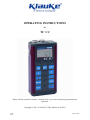
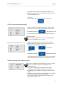
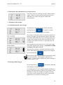
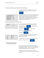
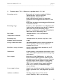
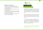
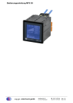
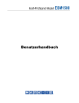
TC1U Bedienungsanleitung TC1U Elektronisches Hand-MessgerÄt Bedienungsanleitung Revision 11-07-12 TKZ L3160-00-72.54DE € Gustav Klauke GmbH Rev. 2011-07-12 Alle Rechte vorbehalten Seite D1 von 14 TC1U Bedienungsanleitung Inhalt 1 2 3 3.1 3.2 3.3 3.4 3.5 3.6 4 5 6 7 8 1 Einleitung .............................................................................................................................. 2 Beschreibung des Messger•tes ........................................................................................ 3 Bedienung des Messger•tes.............................................................................................. 5 Einschalten ............................................................................................................................. 5 Ger€t initialisieren................................................................................................................... 6 Messung vorbereiten.............................................................................................................. 6 Messung durchf•hren ............................................................................................................ 9 Messwerte speichern ...........................................................................................................10 Gespeicherte Werte anzeigen.............................................................................................11 Daten zum Computer ‚bertragen ....................................................................................11 Technische Daten ..............................................................................................................12 Anschlussbelegung...........................................................................................................13 Fehlersuche und –behebung............................................................................................14 Herstelleradresse ...............................................................................................................14 Einleitung Geltungsbereich Die vorliegende Bedienungsanleitung gilt f•r elektronische Hand-Messger€te, die mit “TC1U” bezeichnet sind. Sinn dieses Handbuchs Diese Bedienungsanleitung soll den Anwender bei seiner t€glichen Arbeit mit dem Messger€t unterst•tzen, Es enth€lt Informationen •ber Eing€nge, Bedienelemente und Funktionen des Messger€tes und erl€utert bestimmte Abl€ufe und Bedienhandlungen. F•r Informationen, die •ber den Inhalt dieser Anleitung hinaus gehen, bieten wir Ihnen gerne kundenspezifische Schulungen an. Copyright Das Messger€t und diese Anleitung sind urheberrechtlich gesch•tzt. Jegliche Ver€nderung oder Verwendung ohne Genehmigung wird gerichtlich verfolgt. Wir behalten uns alle Rechte an diesem Handbuch vor, auch die der Reproduktion und/oder Vervielf€ltigung in irgend einer denkbaren Form, z.B. durch fotokopieren, Druck, auf irgendwelchen Datentr€gern oder in •bersetzter Form. Nachdruck dieses Handbuches nur mit schriftlicher Genehmigung der Gustav Klauke GmbH. Der technische Stand zum Zeitpunkt der Auslieferung von Messger€t und Anleitung ist entscheidend, falls keine anderen Informationen gegeben werden. Wir behalten uns technische „nderungen ohne spezielle Ank•ndigung vor. Fr•here Anleitungen verlieren ihre G•ltigkeit. Es gelten die Allgemeinen Verkaufs- und Lieferbedingungen der Gustav Klauke GmbH. € Gustav Klauke GmbH Rev. 2011-07-12 Alle Rechte vorbehalten Seite 2 von 14 TC1U Bedienungsanleitung Haftungsausschluss Wir garantieren die fehlerfreie Funktion unseres Produktes gem€… unserer Werbung, den von uns herausgegebenen Produktinformationen und dieser Anleitung. Weiter gehende Produkteigenschaften werden nicht zugesagt. Wir •bernehmen keine Haftung f•r Wirtschaftlichkeit und fehlerfreie Funktion, wenn das Produkt f•r einen anderen Zweck eingesetzt wird, als im Abschnitt "Bestimmungsgem€…e Verwendung" beschrieben wird. Schadenersatz ist generell ausgeschlossen, au…er falls Vorsatz oder grobe Fahrl€ssigkeit seitens der Gustav Klauke GmbH nachgewiesen wird oder falls zugesagte Produkteigenschaften nicht vorhanden sind. Wird dieses Produkt in Umgebungen eingesetzt, f•r die es nicht geeignet ist oder die dem technischen Standard nicht entsprechen, sind wir f•r die Folgen nicht verantwortlich. Wir •bernehmen keine Haftung f•r Sch€den an Einrichtungen und Systemen in der Umgebung des Produktes, die durch einen Fehler des Produktes oder in dieser Anleitung verursacht werden. Wir sind nicht verantwortlich f•r die Verletzung von Patenten und/oder anderen Rechten Dritter au…erhalb der Bundesrepublik Deutschland. Wir sind nicht haftbar f•r Sch€den, die durch unsachgem€…e Bedienung und Nicht-Befolgung der Anweisungen in dieser Anleitung entstehen. Wir haften nicht f•r entgangenen Gewinn und Folgesch€den aufgrund der Nicht-Beachtung von Sicherheits- und Warnhinweisen. Die Produkte der Gustav Klauke GmbH entsprechen dem Stand von Wissenschaft und Technik. Der Hersteller f•hrt laufend Untersuchungen der Produkte und des Marktes durch, um die st€ndige Weiterentwicklung und Verbesserung ihrer Produkte voran zu treiben. Im Falle von St†rungen und/oder technischen Problemen wenden Sie sich bitte an unseren Kundendienst. Wir sichern Ihnen zu, dass umgehend geeignete Ma…nahmen eingeleitet werden. Hinsichtlich Sachm€ngelhaftung und Gew€hrleistung gelten die entsprechenden Bestimmungen der Gustav Klauke GmbH, die wir Ihnen auf Wunsch gerne zukommen lassen. Bestimmungsgem•„e Verwendung Das elektronische Hand-Messger€t TC1U wird verwendet f•r Anzeige und Aufzeichnung der Signale von Sensoren mit normierten, analogen Ausgangssignalen von 4 bis 20 mA. Der Messkanal p ist nur zur Druckmessung vorbereitet, am zweiten Messkanal F kann ein Kraftsensor angeschlossen werden. F•r die Daten•bertragung zu einem Computer ist eine USB Schnittstelle vorgesehen. Falls Sie Fragen haben, oder das Messger€t f•r einen anderen Zweck verwenden m†chten, wenden Sie sich bitte an unseren Kundendienst. 2 Beschreibung des Messger•tes Das TC1U ist ein leistungsf€higes Hand-Messger€t zur Anzeige und Aufzeichnung von Messwerten, speziell der Messgr†…en Kraft und Druck. Das Ger€t hat einen internen Speicher f•r maximal 500.000 Messwerte zur Aufnahme und Speicherung der gemessenen physikalischen Messgr†…en. Diese Messdaten k†nnen •ber eine USB-Schnittstelle zu einem PC •bertragen werden. Durch wieder aufladbare NiMH-Akkus ist das Messger€t unabh€ngig von einer Stromquelle einsetzbar, f•r das Nachladen wird ein Steckernetzger€t mitgeliefert. Das TC1U ist mit zwei Messeing€ngen f•r den Anschluss von Sensoren mit normiertem, analogen Ausgangssignal (4 ... 20 mA) ausgestattet. € Gustav Klauke GmbH Rev. 2011-07-12 Alle Rechte vorbehalten Seite 3 von 14 TC1U Bedienungsanleitung Anschlussm…glichkeiten Umgang mit den Ger•te-Akkus Wichtig Laden Sie vor dem ersten Einschalten des MessgerÄtes den Akku vollstÄndig auf. Dies dauert ca. 16 Stunden und gewÄhrleistet die volle Akku-KapazitÄt. Stellen Sie vor dem Einsatz des Messger€tes sicher, dass der Akku ausreichend geladen ist. Schlie…en Sie es an das mitgelieferte Steckernetzger€t an um den Akku zu laden. Einen entladenen Akku vollst€ndig aufzuladen dauert etwa 16 Stunden. Um die Lebensdauer der verbauten NiMH-Zellen zu gew€hrleisten sollten Sie vollst€ndige Entladung, € Gustav Klauke GmbH Rev. 2011-07-12 Alle Rechte vorbehalten Seite 4 von 14 TC1U Bedienungsanleitung Dauerladung. sowie sofortiges Nachladen nach jedem Gebrauch vermeiden. Eine Entladung unter 50 % und eine anschlie…ende Aufladung wirkt sich positiv auf die Lebensdauer der Zellen aus. Verbrauchte Akkus d•rfen nicht im Hausm•ll entsorgt werden. Bitte f•hren Sie sie einer ordnungsgem€…en Entsorgung zu. Wichtige Hinweise Setzen Sie das Ger€t nie •berm€…iger W€rme oder Feuchtigkeit aus. ‡ffnen Sie niemals das Ger€t. Ziehen Sie w€hrend eines Gewitters unbedingt den Netzstecker aus der Steckdose, oder wenn Sie eine Geruchs- oder Rauchentwicklung feststellen. Sch•tzen Sie Ihre Sensoren vor dem ˆberschreiten des zul€ssigen Spannungsversorgungsbereiches, einer mechanischen Belastung •ber den zul€ssigen Messbereich hinaus, sowie falschen Anschlussbelegungen, insbesondere bei Sensoren von Fremdherstellern. Reinigen Sie das Messger€t nur mit einem weichen Tuch, das leicht mit mildem Haushaltsreiniger angefeuchtet sein darf. Verwenden Sie keinesfalls starke chemische L†semittel, da sie das Geh€use angreifen. 3 Bedienung des Messger•tes Allgemeine Anmerkungen Die angezeigten Bildschirme werden in dieser Anleitung nur ann€hernd exakt dargestellt, die Inhalte stimmen jedoch mit dem Messger€t •berein. Werden Tasten erw€hnt, so steht deren Bezeichnung in eckigen Klammern, z.B. [ON]. 3.1 Einschalten Dr•cken Sie ca. 2 Sekunden die Taste [ON], f•r etwa drei Sekunden erscheint diese Anzeige: TC1U Init 1.0f SN: 000333 Klauke Textron Danach wird die Messwertanzeige aufgerufen, die z.B. so aussehen k†nnte: TF 70 [kN] F^ 61.8 65.7 Hier wird oben der aktuelle Kraft-Messwert angezeigt, darunter der maximale Kraft-Messwert seit Beginn der Messung. Dr•cken Sie die Taste [p] um zur Anzeige des Druckes umzuschalten: TP 1000 p [bar] p ^ [bar] 464 537 Mit [F] k†nnen Sie wieder zur Anzeige der Kraftmesswerte zur•ckkehren. € Gustav Klauke GmbH Rev. 2011-07-12 Alle Rechte vorbehalten Seite 5 von 14 TC1U 3.2 Bedienungsanleitung Ger•t initialisieren Bei sehr starken elektromagnetischen St†rungen, die •ber den Werten der EN 50081 und EN 50082 liegen, kann es in industriellen Anlagen vorkommen, dass Informationen in digitalen Speichersystemen verf€lscht bzw. gest†rt werden. Dies kann zu unwahrscheinlichen Messwerten oder zum Ausbleiben von Ger€tefunktionen f•hren. F•r diesen Fall k†nnen Sie durch eine Neu-Initialisierung alle Einstellungen auf Werkseinstellungen zur•ckzusetzen. Dadurch verlieren Sie jedoch alle eingegebenen Daten und Parameter, wie Kalibrierwerte, Einheiten, Stromausgang der Druck- und Kraftsensoren. 1. Schalten Sie das Messger€t ein. 2. Dr•cken Sie w€hrend der drei Sekunden der Initialisierung die Tastenfolge [p] [F] []: init > complete yes > enter no > SI/US 3. Dr•cken Sie [Prog/Enter] um die Initialisierung zu beginnen. F•r einen kurzen Moment wird „init complete“ angezeigt, danach erscheint die Messwertanzeige. Das Ger€t hat nun diese Grundeinstellungen: Druckmessung Messbereich Ma…einheiten Sprache 3.3 p 0 ... 1000 bar SI deutsch Messung vorbereiten Wichtig SchlieÅen Sie Kraftsensoren nur an das MessgerÄt an, wenn sie nicht belastet sind. Ansonsten kann es zu Fehlmessungen kommen. Sensoren mit ISDS Das Messger€t TC1U ist mit einer automatischen Sensorerkennung ausgestattet. Ein im Sensor integrierter Chip speichert die wichtigsten Sensor- und Kalibrierinformationen, z.B. Messbereich physikalische Messgr†…e Ma…einheit Ausgangssignal charakteristische Kennlinie Um diese Daten zum Messger€t zu •bertragen schlie…en Sie zun€chst den Sensor an und schalten danach das Ger€t ein. Nach der Initialisierung kann die Messung sofort beginnen. € Gustav Klauke GmbH Rev. 2011-07-12 Alle Rechte vorbehalten Seite 6 von 14 TC1U Bedienungsanleitung Einsatz von Kraftsensoren ohne ISDS 1. Schlie…en Sie den gew•nschten Kraftsensor an. Er darf jedoch nicht belastet sein! Notieren Sie sich den Kraftmessbereich, der auf dem Typenschild des Sensors enthalten ist. 2. Schalten Sie das Messger€t ein und warten Sie, bis die Messwertanzeige erscheint. 3. Dr•cken Sie ca. zwei Sekunden lang [F]: *** PROG F *** 0 ... 70.00 kN 0 ... 15736 lbF 4. Der aktuell eingestellte Kraftmessbereich wird angezeigt. Dr•cken Sie [] um den Kraftmessbereich zu €ndern: *** PROG F *** 0 ... 130.00 kN 0 ... 29225 lbF 5. Dr•cken Sie [] so oft, bis der gew•nschte Kraftmessbereich angezeigt wird. Das Ger€t unterst•tzt die Kraftmessbereiche 0 ... 10 / 20 / 70 / 130 kN. 6. Dr•cken Sie [Prog/Enter] um die Einstellung zu best€tigen. Danach beginnt eine automatische Korrektur des Nullpunktes: * Nullpunktkorrektur * ACHTUNG Der Sensor muss unbelastet sein! Prog/Enter > Start 7. Stellen Sie sicher, dass der Sensor unbelastet ist. Dr•cken Sie dann [Prog/Enter] um die Korrektur des Nullpunktes zu starten. Nach wenigen Sekunden erscheint die Messwertanzeige. Einsatz von Drucksensoren ohne ISDS 1. Schlie…en Sie den gew•nschten Drucksensor an. Er darf jedoch nicht belastet sein! Notieren Sie sich den Druckmessbereich, der auf dem Typenschild des Sensors enthalten ist. 2. Schalten Sie das Messger€t ein und warten Sie, bis die Messwertanzeige erscheint. 3. Dr•cken Sie ca. zwei Sekunden lang [p]: *** PROG P *** 0 ... 1000 bar 0 ... 14500 psi 4. Der aktuell eingestellte Druckmessbereich wird angezeigt. Dr•cken Sie [] um den Druckmessbereich zu €ndern: € Gustav Klauke GmbH Rev. 2011-07-12 Alle Rechte vorbehalten Seite 7 von 14 TC1U Bedienungsanleitung *** PROG P *** 0 ... 750 kN 0 ... 10900 psi 5. Dr•cken Sie [] so oft, bis der gew•nschte Druckmessbereich angezeigt wird. Das Ger€t unterst•tzt die Druckmessbereiche 0 ... 750 / 1000 bar. 6. Dr•cken Sie [Prog/Enter] um die Einstellung zu best€tigen. Danach beginnt eine automatische Korrektur des Nullpunktes: * Nullpunktkorrektur * ACHTUNG Der Sensor muss unbelastet sein! Prog/Enter > Start 7. Stellen Sie sicher, dass der Sensor unbelastet ist. Dr•cken Sie dann [Prog/Enter] um die Korrektur des Nullpunktes zu starten. Nach wenigen Sekunden erscheint die Messwertanzeige. Freie Einstellung von Messbereichen Neben den voreingestellten Messbereichen k†nnen Sie die beiden Messkan€le auch mit frei eingegebenen Messbereichen programmieren. Im folgenden Ablauf ist die Programmierung f•r den Messkanal „Kraft“ beschrieben, die Programmierung f•r den Messkanal „Druck“ erfolgt analog, Sie m•ssen nur jeweils statt der Taste [F] die Taste [p] dr•cken. 1. Dr•cken Sie in der Messwertanzeige die Tastenfolge [Prog/Enter] [F]. 2. Eventuell m•ssen Sie [] dr•cken, um das Sternsymbol * neben den Begriff “Kalibrierwert” zu stellen: *** PROG F *** * Kalibrierwert Nullpunktabgleich Prog/Enter > Best€tigen 3. Dr•cken Sie [Prog/Enter] um den Kalibrierwert (= Messbereichsgrenze) einzugeben: *** PROG F *** 0 ... 70.0 kN 0 ... 15736 lbF 4. 5. 6. 7. € Gustav Klauke GmbH Rev. 2011-07-12 Der Cursor steht unter der ersten Ziffer (hier: 7), diese Ziffer kann ver€ndert werden. Dr•cken Sie mehrmals [] um durch die zur Verf•gung stehenden Ziffern/Zeichen zu bl€ttern. Dr•cken Sie [] um zum n€chsten Zeichen zu springen. Dr•cken Sie [Prog/Enter] um den eingegebenen Wert zu best€tigen. Erst dadurch werden die grau dargestellten US-Einheiten aktualisiert. Danach erscheint die Messwertanzeige. Alle Rechte vorbehalten Seite 8 von 14 TC1U 3.4 Bedienungsanleitung Messung durchf‚hren Nach dem Anschlie…en, Einschalten und Programmieren werden die aktuellen Messwerte angezeigt: TF 70 [kN] F^ 61.8 65.7 Hier wird oben der aktuelle Kraft-Messwert angezeigt, darunter der maximale Kraft-Messwert seit Beginn der Messung. Dr•cken Sie die Taste [Clear] um den Maximalwert beider Messkan€le (Kraft und Druck) zu l†schen. Es wird dann zun€chst der aktuelle Messwert als Maximalwert angezeigt. Wenn auch ein Drucksensor angeschlossen ist, k†nnen Sie [p] dr•cken um dessen Mess- und Maximalwerte anzuzeigen: TP 1000 p [bar] p ^ [bar] 464 537 Anzeige eines Sensorfehlers TP 1000 p [bar] p ^ [bar] ---0.0 Das Messger€t empf€ngt keine Signale vom Sensor. Pr•fen Sie: Ist das Messkabel richtig an Sensor und Messger€t angeschlossen? Liegt ein Kabelbruch vor (anderes Messkabel ausprobieren)? Ist der Sensor defekt (anderen Sensor ausprobieren)? Wenn Sie einen ISDS Sensor neu anschlie…en m•ssen Sie das Messger€t aus- und wieder einschalten, damit die ISDS Daten eingelesen werden k†nnen. € Gustav Klauke GmbH Rev. 2011-07-12 Alle Rechte vorbehalten Seite 9 von 14 TC1U 3.5 Bedienungsanleitung Messwerte speichern Spitzenwerte speichern 1. Zeigen Sie einen der beiden Kan€le in der Messwertanzeige an. 2. Dr•cken Sie [Clear] ca. zwei Sekunden lang: TP 1000 p [bar] p ^ [bar] 48 697 3. Der Balken rechts zeigt an, dass das Ger€t bereit zur Speicherung ist. Die Datenaufzeichnung beginnt automatisch, sobald 7% des programmierten Maximalwertes •berschritten wurden und endet automatisch, wenn 4% des Wertes unterschritten werden. Es werden stets beide Kan€le mit einer Abtastrate von 1 ms gespeichert. TP 1000 p [bar] p ^ [bar] 48 697 4. Sie k†nnen auch [Clear] dr•cken um die Speicherung abzubrechen. Pressvorgang speichern 1. Zeigen Sie einen der beiden Kan€le in der Messwertanzeige an. 2. Dr•cken Sie [Memory]; alternativ k†nnen Sie auch nacheinander die Tasten [Enter] und [Clear] dr•cken: TP 1000 p [bar] p ^ [bar] 48 697 3. Der Balken rechts zeigt den Verlauf der Speicherung, diese wird eine Minute lang fortgesetzt, wobei beide Messkan€le aufgezeichnet werden. TP 1000 p [bar] p ^ [bar] 48 697 4. Sie k†nnen auch [Clear] dr•cken um die Speicherung abzubrechen. € Gustav Klauke GmbH Rev. 2011-07-12 Alle Rechte vorbehalten Seite 10 von 14 TC1U 3.6 Bedienungsanleitung Gespeicherte Werte anzeigen 1. Dr•cken Sie [Output]: F^ Mittelwert: Anzahl Zyklen: Kleinster Wert: Gr†…ter Wert: Standardabw.: 63.7 68 61.8 66.9 3.2 2. In der ersten Zeile wird der Mittelwert der maximalen Kraft angegeben, darunter die Anzahl der Verpressungen (Zyklen). In der dritten und vierten Zeile wird die kleinste/gr†…te Kraft gezeigt, ganz unten die berechnete Standardabweichung vom Mittel aller Messwerte. 3. Dr•cken Sie noch einmal [Output]: Zyklus Nr: F ^: 1 66.9 4. Hier wird die maximale Kraft angezeigt, die in Verpressung 1 gemessen wurde. Dr•cken [] / [] um den Messwert des n€chsten/vorherigen Zyklus anzuzeigen. Halten Sie die jeweilige Taste gedr•ckt laufen die Zyklen schnell durch. 5. Dr•cken Sie [Output] um zur Messwertanzeige zur•ckzukehren. 4 Daten zum Computer ‚bertragen Zur ˆbertragung der Messdaten verbinden Sie das Messger€t •ber ein USB-Kabel mit dem PC, starten die erforderliche Software (Zubeh†r) und schalten dann das Messger€t ein. Alle weiteren Schritte werden mit der Klauke-Software durchgef•hrt. € Gustav Klauke GmbH Rev. 2011-07-12 Alle Rechte vorbehalten Seite 11 von 14 TC1U 5 Bedienungsanleitung Technische Daten Messeing€nge 2 x 6-polige Buchsen M16 x 0,75 p nur f•r Druck-, F nur f•r Kraftmessung Eingangssignal 4 ... 20 mA. Schnittstelle USB zum Anschlu… an PC Messbereich p frei einstellbar oder fest auf 750 / 1.000 bar Messbereich F frei einstellbar oder fest auf 10 / 20 / 70 / 130 kN Fehlergrenze Š 0,5 % vom Endwert (bei 20 ‹C Š 3 K) Temperaturkoeffizient Š 0,2 % / 10 K Me…rate 1 ms Aufl†sung A/D-Wandler 12 Bit Messwertspeicher max. 500.000 Messwerte Maximalwertspeicher wahlweise von p oder F Anzeige Grafikdisplay, Messwertdarstellung max. f•nfstellig Stromversorgung intern 14,4 V DC NiMH-Akku, 1,1 Ah f•r ca. 10 Std. externe •ber Steckernetzger€t 230 / 115 V AC, sekund€r 24 V DC Sensorspeisespannung 24 V Umgebungsbedingungen Betriebstemperatur: 0 ... 50 ‹C, relative Feuchte <80%, nicht betauend Geh€usewerkstoff Aluminium / ABS-Kunststoff Abmessungen 165 x 80 x 40 mm (L x B x H) Gewicht ca. 720 g € Gustav Klauke GmbH Rev. 2011-07-12 Alle Rechte vorbehalten Seite 12 von 14 TC1U 6 Bedienungsanleitung Anschlussbelegung Eing•nge p/F Pinbelegung (Draufsicht) Analoger Signaleingang 4 ... 20 mA, 2-Leiter 1 Signal – (I-) / RL 100 Ω 2 frei 3 Signal + (I+) / *14.4 VDC / IOUT max. 50 mA 4 ISDS 5 Kabelschirm 6 ISDS Achtung bei Anschluss von Sensoren anderer Hersteller: Bei Anschlu… einer externen Spannungsversorgung, z. B. •ber Netzadapter, ist die Speisespannung der Sensoren gleich der Netzadapterspannung von 24 VDC (- ca. 1,5 V). In F€llen, wo eine freie externe Speisespannung f•r das Messger€t verwendet wird, kann die Spannungsversorgung f•r die Sensoren zwischen 24 ... 30 VDC (- ca. 1,5 V) liegen. € Gustav Klauke GmbH Rev. 2011-07-12 Alle Rechte vorbehalten Seite 13 von 14 TC1U 7 8 Bedienungsanleitung Fehlersuche und –behebung St…rung / Fehler Ursache / Behebung nach dem Einschalten des Ger€tes keine Anzeige Akkus leer, mit Netzadapter 230 VAC / sekund€r 24 VDC Akkus 14-16 Stunden aufladen nur waagerechte Striche in der Messwertanzeige Sensor bzw. Messkabel nicht angeschlossen oder defekt; beide Teile nacheinander wechseln falscher Nullpunktabgleich; zu hohe Werte in der Messwertanzeige Nullpunktabgleich wurde durchgef•hrt als Sensor nicht druck- bzw. kraftlos war; wiederholen Sie den Nullpunktabgleich wie vorn beschrieben „Over“ wird angezeigt Messbereich wurde •berschritten; Kurzschluss in Sensor oder Kabel; Messzelle wurde mechanisch •berlastet (•berdr•ckt) „Akku laden“ wird angezeigt laden Sie die internen Akkus mit dem externen Netzteil f•r ca. 16 Stunden auf Herstelleradresse Wenn Sie Probleme mit dem Messger€t haben, oder es kalibrieren, warten oder reparieren lassen m†chten, so wenden Sie sich bitte an: Klauke Servicecenter Gustav Klauke GmbH Auf der Knapp 46 • D-42855 Remscheid Tel.: +49 (0) 2191-907 242 • Fax +49 (0) 2191-907 243 www.klauke.textron.com • e-Mail: [email protected] € Gustav Klauke GmbH Rev. 2011-07-12 Alle Rechte vorbehalten Seite 14 von 14 OPERATING INSTRUCTIONS for TC 1 U Please read the operation remarks carefully before you set the measuring instrument into operation. Copyright © 2011 L3160-00-72.54D, Edition 06.07.2011 JCS HE. .... TC1Ue.doc Instruction Manual TC 1 U page 2 ___________________________________________________________________________ Preface The present operating instructions are a description for the hand-measuring instrument TC1U with the following measuring entries: − 2 Measuring entries, intended for sensors with normalized, analogue output signals from 4 to 20 mA: The measuring channel p is for pressure measuring only. In the second measuring channel F is for a force sensor. − 1 USB interface to transfer measured values to the PC. The operation of the TC 1 U will certainly not make any difficulties for you, however you can only exploit all features when you exactly know the appliance. Should you nevertheless have difficulties with this unit we are happy to assist you. Changes serving the technical progress are made w/o prior notice. We wish you every success when utilising your hand-measuring instrument: TC 1 U 2 Instruction Manual TC 1 U page 3 ___________________________________________________________________________ Index General............................................................................................................................ Remarks on the correct charging of the internal battery of the unit..................... Measures of precaution, service instruction.......................................................... 4 5 6 1. 1.1 1.2 Operation of TC 1 U........................................................................................... Sample displays.................................................................................................... Initializing............................................................................................................ 7 7 8 2. 2.1 2.2 2.3 2.4 Preparations for force-sensing resp. pressure measuring............................ Explanation and connection of the ISDS-Sensors……………………….......... Selection of the prefixed force measuring ranges…………………………….. Choice of the prefixed pressure measuring ranges............................................. Adjustment of completely optional force- resp. pressure-measuring ranges as calibration value............................................................................................ Force- resp. pressure-measuring........................................................................ Error message at 4 to 20 mA-sensors................................................................ Data display at 4 to 20 mA-sensors................................................................... 9 9 10 11 2.5 2.6 2.7 12 13 13 13 14 14 14 3.4 Measured value storage................................................................................. Automatical peak value storage....................................................................... Storing without trigger..................................................................................... Display of stored peak values directly on the screen (with trigger function)...................................................................................... Display of all single, stored peak values.......................................................... 4. Data transfer of the saved data to the PC.................................................... 15 5. Technical data of TC 1 U............................................................................... 16 6. Pin configurations of the TC 1 U................................................................... 17 7. Technical informations on the connection of pressure- and force-sensors in 4 to 20 mA-design........................................................................................ 18 8. Trouble shooting.............................................................................................. 19 9. Informations on warranty.............................................................................. 20 10. Maintenance.................................................................................................... 20 3. 3.1 3.2 3.3 14 15 3 Instruction Manual TC 1 U page 4 ___________________________________________________________________________ General The TC 1 U of the company Klauke is an efficient hand-measuring device for the measuring of force resp. pressure and their maximum values. The TC1U has an internal memory (approx. 60 000 measured values) to record and save the physical data being measured. This data can be transmitted to a computer via a USB interface. Rechargeable NiMH batteries make the TC 1 U independent of an external power source. An external charger is available to recharge the battery. The appliance has 2 measuring ports for the connection of sensors with a standardized, analogous output signal from 4 to 20 mA (milli-amps). Force measuring Force sensor with amplifier 4 to 20 mA, with or w/o ISDS Ports of the TC 1 U Pressure measuring Pressure sensor type HD 4 to 20 mA with or w/o ISDS P F USB interface Battery Charger network adapter 230 VAC secondary 24 VAC 4 Instruction Manual TC 1 U page 5 ___________________________________________________________________________ Notes on proper charging of the internal battery Before each use of the TC 1 U please make sure that the internal NiMH-batteries always have a sufficient capacity. When operating the Klauke mains adapter (primary 230 VAC, secondary 24 VDC/340 mA) a continuous charging of the battery is guaranteed. When operating the TC 1 U for the first time please note that the batteries must be charged prior. The unit should be charged 14 to 16 hours. Always use the Klauke mains adapter to re-charge the battery. When the battery is discharged, the charging time should be 16 hours while the appliance is switched off. The working life of NiMH-cells can be very long but it is dependent on the operating conditions. A complete discharge resp. permanent charging or an immediate recharging after each application should be avoided. Discharging just below 50 % and then recharging has a favourable effect on the working life of the NiMH cells. A re-charging after only a short operating time has a negative impact as this results in the so called ‘memory-effect’ which causes a decrease of the battery capacity. If the battery is discharged only partially and then re-charged again several times, the cell will soon show a lower capacity. Is this handling continued for a longer period of time, the battery can be damaged permanently. However the battery can be regenerated by a longer use of the TC 1 U and a subsequent recharging. An insufficiently charged battery is notified in the display with the remark „Charge battery!“. In this case the battery is discharged to a degree that a charging time of 16 hours is mandatory. 5 Instruction Manual TC 1 U page 6 ___________________________________________________________________________ Please also observe the following, important remarks, concerning your safety and the operational reliability of the appliance: - Please never expose the appliance to excessive heat or humidity. - Don’t open the appliance yourself. - In case of a mains operation please unplug the mains adapter off the socket: 1. during a thunderstorm, 2. if you detect a smell or smoke. - Please protect your sensors against: 1. exceeding of the approved voltage range, 2. mechanical overload acceeding the approved measuring range, 3. wrong pin connections, especially with regard to sensors of other manufacturers For special attention: If the housing is dirty, clean it with a soft cloth which is slightly moisturized by a mild domestic detergent (pls. regard the comments of the detergent manufacturer). Do not use strong chemical solvents as they damage the housing. Recycling for environment’s sake Make a contribution to the environmental protection! Do not dispose off used batteries in regular garbage! Please dispose off your batteries environmental friendly (special waste). 6 Instruction Manual TC 1 U page 7 ___________________________________________________________________________ Operation of TC 1 U The LCD-display is capable to present two measured values with their peak value. The first line displays the physically measured value and the second line displays the maximun value. 1.1 Display examples Inputs are generally confirmed by actuating the entry key Prog/ENT. Initializing Version 2.0 (Klauke) TF 70 61,8 [kN] F^ After the TC 1 U is switched on it shows this display for about 3 seconds. Afterwards the screen automatically displays the measured value-indicator. In our example the force-sensing value F is indicated with its maximum value. 65.7 TP1000 If the measured value of p (pressure) shall be indicated in the same way simply press the key [bar]^46.4 and the corresponding measured value for the pressure with its maximum value appears on the screen. 53.7 F 70 [kN] 61,8 F^ Actuating the key . ..................... again returns you to the corresponding force value F. 65,7 7 Instruction Manual TC 1 U page 8 ___________________________________________________________________________ 1.2 Initializing In industrial plants strong electromagnetic interferences acceeding the values published in the EN 50081 and EN 50082, may distort resp. disturb results in digital electronic devices. This becomes apparent when unlikely measuring data is generated or when the unit does not reakt on any input. In this case you have the possibility to set the unit on the initial pre-set default parameters. However all your parameters you fed in before such as calibration value, measuring units, current output of the pressure sensors and force sensors will then be deleted. Initializing Version 1.xx To return to the default parameter actuate the following keys: …… ..and and . The input has to be made within 3 seconds. Int > complete Yes > enter No > SI/US The call for inititialization appears automatically. You can decide whether you like to initialize or not. If no inititialization is requested actuate the button SI/US and the measuring display appears automatically. Afterwards you can choose German, English or French as operation language. SPRACHE/LANGUAGE This will be done with the key . ↑ -English- ↑ -Franςais- ↑ The choice is to be confirmed with the key Prog/ENT. . *****UNIT***** SI Afterwards the notification for the choice of the Sl resp. US-measuring units comes automatically. With the key you can change from Sl- to the US-measuring units. Confirm the choice with the key Prog/ENT. SI-units are e.g. bar, kN etc. When switching over to USmeasuring units the common scales are e.g. psi or am. to. 8 Instruction Manual TC 1 U page 9 ___________________________________________________________________________ 2.Preparations for force-sensing resp. pressure measuring In order to measure a force, first the force sensor without load has to be connected. Please do not disregard this notice that no miss-measurement ocures The marking of the ISDS-Sensors is According to the following examples: Without ISDS = Type TF70 with ISDS = Type TF70S 2.1 Explanation and connection of the ISDS sensors The meter TC 1 S is equipped with a automatic sensor recognition. A chip integrated in the sensor incorporates an EEPROM with all calibration and manufacturer information just as • Measuring range • Physical Measurement • Units • Signal • Characteristic curve Example of a standard Force sensor with ISDS When the sensor is connected and the meter is switched on the sensor data will be transfered to the meter automatically. The time consuming transfer of the sensor data from data sheets and the mix-up of different sensors is history from now on. In daily operation a positive and safe identification of the sensor data is provided and an improved operating comfort is the result. In addition due to the saved linearization data we gain a higher metering precision of the sensor which can not be achieved with standard meters. Monitoring sensor specific re-calibration data allows an early identification of sensor diviations and therefore helps to avoid test rigs and data loses. 9 Instruction Manual TC 1 U page 10 ___________________________________________________________________________ 2.2 Selection of the default force measuring range with automatic zero correction of sensors without ISDS The key F has to be pressed for about 2 seconds. In the called-in notice in our example you can see the measuring range „0 ... 100 kN“. With the key ↑ which has now the effect of an arrow head key you can call in further force-measuring ranges in kN. The chosen force measuring range has to coincide with the measuring range of the sensor. Remark: The force measuring range is always stated on the decal of the sensor. The picture on the left hand side explains the scope by means of the arrow head key. By pressing the key Prog/ENT the choice is confirmed. Attention: After reinstallation/calibration the value will be set to 70 kN (default). To change to an other calibration value, a further values of 10/20/70/130 kN are available. After selecting the force measuring range a note appears in the display that the automatic Zero Correction must be made without a force load. Actuate the button to start the automatic Zero Correction. This can be recognized by the rotating dashed line which briefly appears on the display in order to save the calibration value and Zero Correction. Afterwards the program returns into the normal measuring menue. 10 Instruction Manual TC 1 U page 11 ___________________________________________________________________________ 2.3 Selection of the pressure measuring range In order to measure the pressure the same way connect the pressure sensor TP1000 in an unloaded state first. Do not disregards this note to avoid incorrect measurements. Actuate for approximately 2 seconds. In the display for example the measuring range „0 ... 1000 bar“ appears. You can make changes with the arrow keys. Note: The pressure measuring range is always stated on the decal of the sensor. Actuating the button confirms the selection. After selecting the pressure measuring range the following remark is shown on the display warning that the automatic zero correction must be performed without pressure load. Actuate the button to start the automatic Zero Correction. The rotating dashed line which appears briefly in the display indicates that the calibration value and the zero correction is saved. Then the return to the normal measuring menu follows. 11 Instruction Manual TC 1 U page 12 ___________________________________________________________________________ 2.4 Adjustment of completely optional force- resp. pressure measuring ranges as calibration value If you want to adjust the measuring ranges so press the keys and By the key . the star symbol is adjusted to the line„calibration value“. With the key the choice is confirmed. The following menu appears. In our example a special force sensor of 70 kN is adjusted to the final value of its measuring range. Please observe the cursor below the figure. Please just try the input recording to our example in order to get a little practice. After that you just have to confirm the input of figures with the key . Briefly afterwards the familar screen with the measured values automatically appears again. If you want to input a calibration value for a special pressure sensoryou have to select the sequence of keys and . The course for the input of pressure-calibration value „p“ is taken place in analogy to the previously described operational follow-up for „force“. The 12 Instruction Manual TC 1 U page 13 ___________________________________________________________________________ proceedure for the pressure calibration input „p“ is happening in the same way than described previously for force calibration „F“. Attention: The US-units will be excepted when actuating 2.5 Force resp. pressure measuring Indication of measured force value In our example the present force of 61,8 kN and the peak value of 65,7 kN are both shown on the screen. By actuating the key , the peak force can be reset to the present force at the sensor at any time. Please observe! A reset of the peak value to zero will only happen if there is no load at the force sensor. Indication of measured pressure value If there is a force sensor as well a pressure sensor connected, their measured value can be seen in the display by actuating both of the keys or one after the another. Actuating of the key simultaneously puts also both the peak values for force resp. pressure back to the initially measured force- resp. pressure-values. 2.6 Error message at 4 to 20 mA-sensors If you are confronted with a display as the one on the left side, no current signal is transmitted to the measuring entry. A reason for this might be missing connections (missing measuring cables) between sensor and measuring entry, a break of a cable or a defect of the sensor. In this case an optical status information in the display advises you of possible causes of trouble. This optical signal is only possible for the currentsignal from 4 to 20 mA. 13 Instruction Manual TC 1 U page 14 ___________________________________________________________________________ 2.7 Measured value indication at 4 to 20 mA-sensors If the force sensor is working correctly, which means a signal ≥ 4mA is present, the normal measured value indication (see on the left) appears without the horizontal line. 3 Measured value storage 3.1 Automatical peak value storage An automatic peak value storage can be started by pressing the key …………….. for about 2 seconds. All previous peak value storages are deleted. The storage of the peak value of a pressing operation is made by a trigger, provided that the trigger value must have fallen short within the scope of the pressing cycle so that a new storage can be carried out. By this, each working cycle which is based on a pressing cycle can be acquired. In the notification a bar chart is to be seen on the right side which signalizes the storage. A maximum of 1000 working cycles can be stored. Theoretically a storage is finished when the bar chart field is filled. But at any time a storage can be stopped by pressing the key ……………. Please observe that only the channel in particular which was selected before – this might be either force or pressure – is stored. The scanning rate for the storage of the peak value is 1 ms. 3.2 Storing without trigger By pressing the key the channel indicated in the display is being activated. A scanning rate of 2 ms is rigidly adjusted and allows a storage of 60.000 measured values in one minute. With this kind of storage for example a complete pressing cycle can be stored which later on can be represented graphically over a printer as running curve. 14 Instruction Manual TC 1 U page 15 ___________________________________________________________________________ 3.3 Picturing of all single, stored peak values (with trigger) If the peak values of all crimping cycles are to be indicated in the display you have to press the key . Afterwards a display as indicated on the left appears. In the first line the average value of the maximum force is displayed. Below follows the number of crimps (Cycles) and in the 3rd and 4th line the lowest and the maximum force is displayed. In the 5th line the standard diviation is displayed. 3.4 Picturing of all single stored peak values In case the peak force of each single cycle shall be listed resp. indicated, this is achieved by a further actuating of the key …………….; the notification on the left appears.. With the keys ↑ the cycle-number is increased by one figure and decreased with the key → . If you want to accelerate the search process, keep the key pressed constantly. Hereby the scroll speed increases significantly. To get into the normal indication of measured values again, you must press the key . 4 Data tranfer of the stored measured values to the PC For the transfer of the measured data the measuring instrument is connected to the PC via a USB cable. The corresponding software (accessory) is started in the PC, and the measuring instrument is switched on. All further operation steps for the transfer of the measured data to the PC are carried out with the Klauke software. 15 Instruction Manual TC 1 U page 16 ___________________________________________________________________________ 5. . Technical data of TC 1 U (Referece of specified data 20 °C ± 3 K) Measuring entries: Entry hubs of 2 x 6-poles (Amphenol-Tuchel) Measuring entry p only for pressure Measuring entry F only for force, both of the measuring entries are supporting normalized current signals for the sensors of 4 bis 20 mA. Entry hubs 1x6-poles, intersecting point USB for the connection to the PC. Measuring range: Pressure p: free adjustable to according final value of the pressure measuring range fi xed on 1000 bar (final value of pressure measuring range) Force F: free adjustable or fixed on 70 und 130 kN (final value of force measuring value) Error limit: Analogue entries: ± 0,5 % of final value Temperature coefficient: ± 0,2 %/10 K Measuring rate: Analogue entries for pressure resp. force: 1 ms Definition A/D Transformer 12 Bit Storage of measured value: Maximum 60 000 measured values (depend on the choosen quantity to be measured) with fixed scanning rate of 1 ms. Min./Max.- storage of values: Storage of maximum values alternatively p to F directly in the notice. Notification: Graphic display, representation of measured values max. with 5 ciphers (dependent on measuring range and channel) Power supply: Internal 14,4 Volt NiMH-battery, 1,1 Ah for 10 hours of uninterrupted operation with integrated charging connection and battery-advance-warning. External electric tension supply over plug mains apparatus 230 VAC or 115 VAC, secondarily 24 VDC or over external voltage supply (stabilized from 24 V to 30 VDC), recommended supply current 300 mA. Sensor supply voltage: Supply is got from the measuring instrument. With battery operation 14,4 V, and plug mains operation 24 V. Ambiance conditions: Working temperature: 0 °C bis +50 °C, relative humidity: <80%, not moistening 16 Instruction Manual TC 1 U page 17 ___________________________________________________________________________ General: Case material: Aluminium/ABS-sythetic material Dimensions: 165 x 80 x 40 mm (L x W x H) Weight: 0,720 kg In the interest of further technical development we reserve for ourselves the right of changes without previous notice. Our measuring systems are constructed according to the European production standards and fulfill the EG-instructions about the electromagnetic compatibility (EMV) as to EN 50081 and EN 50082. 17 Instruction Manual TC 1 U page 18 ___________________________________________________________________________ 6. Pin configurations of the TC 1 U Jack for external electric voltage supply: 24 V to 30 VDC Small voltage jack of 2-poles according to DIN 45323 Measuring entries: USB interface F P Panel jacks of device Attention: The connection identifiers of the diverse plug manufacturers are different. Please keep to our connecting scheme. Entries (input variables) Pin tying up (plan) 1 2 3 4 5 6 P Analog signal entry 4-20 mA.... 2-conductor ...... signal (ohm) signal +(I+) 14,4VDC Iout max. 50mA ISDS cable screen ISDS F Analog signal entry .... 2-conductor ....... signal (ohm) signal +(I+) 14,4VDC Iout max. 50mA ISDS cable screen ISDS Pay attention in case of connecting sensors of other manufacturers: With the connection of an external electric tension supply e.g. over network adaptor, the supply voltage for the sensors is equal to the network adaptor tension of 24 VDC (-approx. 1,5 V). In cases a free external supply voltage is chosen for the measuring device, the electric tension supply for the sensors is lying between 24 V and 30 VDC (-approx. 1,5 V). 18 Instruction Manual TC 1 U page 19 ___________________________________________________________________________ 8. Technical informations for the connection of pressure- resp. force-sensors in 4 to 20 mA-execution Pressure- resp. force sensor 4-20 mA 2-conductor technics Measuring device TC1U Pin tying-up Measuring instrument TC 1 ......... (internal battery) ......... ohm pin tying-up Warning Notice! Pay attention in case of connecting sensors of other manufacturers: With the connection of an external electric tension supply e.g. over network adaptor, the supply voltage for the sensors is equal to the network adaptor tension of 24 VDC (-approx. 1,5 V). In cases a free external supply voltage is chosen for the measuring device, the electric tension supply for the sensors is lying between 24 V and 30 VDC (-approx. 1,5 V). Please make sure that the sensors which have to be connected are designed for this supply voltage, otherwise these can be destroyed. 19 Instruction Manual TC 1 U page 20 ___________________________________________________________________________ 8. Trouble shooting The TC 1 U was checked and controlled by the manufacturer according to strictest quality standards. Should however arise problems, please first examine the appliance by utilizing with the following list. Error / Operating error Check points / Solutions After connection of the device no indication. Only horizontal lines in the indication of measured values: • Battery flat => Charge batteries with network adaptor 230 VAC/ secondary 24 VDC for 14-16 hours • Sensor resp. measuring cable at sensors of 4 to 20 mA not connected or defective. Please check whether the sensor or the cable is being the cause of the trouble. Please change both of the parts one after the other. • Zero point correction was carried out with sensor being under pressure resp. force. Repeat compensation of zero point correction as described on page 11 / paragraph 2.3 • Entry of measuring range was exeeded - Short circuit of sensor or cable - pressure measuring cell was mechanically overcharged (overstressed) • Over the external socket the batteries of the measuring instrument can be charged with a Klauke network adaptor (230 VAC, secondary 24 VDC or an external voltage of 24 VDC and max. 30 VDC stabilized) Recommended charging time: 14-16 hours. Wrong zero point compensation: values too high in the indication of measured values. „Over“ in the indication. Charge „battery“ in the indication. 20 Instruction Manual TC 1 U page 21 ___________________________________________________________________________ 10. Informations on Warranty For our technical appliances we grant guarantee for perfect condition within the outline policies of our guarantee conditions. The duration of the Warranty period will be 24 months. Fundamentally the general terms of business are valid (see AGB). The guarantee claim expires in case repairs or interferences have been made by persons who are not empowered by us to do so. Within the period of guarantee we repair free of charge damages or defects which are provably basing on a factory-set error in so far as these are reported to us immediately after discovery, at the latest however within six months from date of delivery. The guarantee benefit is effectuated – the way we take stock of it – by a free reconditioning of defective parts or the replacement of them by perfect ones. Appliances for which a giving of a guarantee is claimed are to be forwarded „carriage paid“ and with the corresponding voucher resp. (copy of) delivery note to the Klauke-Service Center _________________________________ 11. Maintenance Your measuring instrument is a high-accuracy appliance which guarantees an operation free from interferences for many years if handled with the appropriate care. If interferences should still arise, please don’t try to repair the appliance by yourself; leave the maintenance resp. repair exclusively to our Klauke-Service Center. Address: Gustav Klauke GmbH Auf dem Knapp 46 D-42855 Remscheid Tel.: + 49 (0) 2191-907 242 Fax: + 49 (0) 2191 907 243 Internet: www.klauke.com e-Mail: [email protected] _________________________________ 21