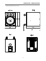
1
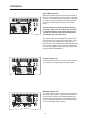
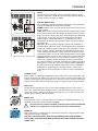
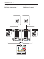
BEDIENUNGSANLEITUNG
OWNER‘S MANUAL
INHALTSVERZEICHNIS
WICHTIGE SICHERHEITSHINWEISE
WICHTIGE SERVICEHINWEISE
BESCHREIBUNG
AUSPACKEN & GARANTIE
QUICK START
BEDIENELEMENTE
INPUT / OUTPUT
LEVEL
STATUS ANZEIGEN
POWER SCHALTER
NETZEINGANG / NETZAUSGANG
AUFBAUBEISPIELE
SPECIFICATIONS / TECHNISCHE DATEN
BLOCK DIAGRAM
DIMENSIONS / ABMESSUNGEN
.......................
.......................
.......................
.......................
.......................
.......................
.......................
.......................
.......................
.......................
.......................
.......................
.......................
.......................
.......................
3
3
4
4
5
6
6
7
7
7
7
15
21
22
23
CONTENTS
IMPORTANT SAFETY INSTRUCTIONS
IMPORTANT SERVICE INSTRUCTIONS
DESCRIPTION
UNPACKING & WARRANTY
QUICK START
CONTROLS
INPUT / OUTPUT
LEVEL
STATUS INDICATORS
POWER SWITCH
MAINS OUT/ MAINS IN
SETUP EXAMPLE
SPECIFICATIONS / TECHNISCHE DATEN
BLOCK DIAGRAM
DIMENSIONS / ABMESSUNGEN
2
.......................
.......................
.......................
.......................
.......................
.......................
.......................
.......................
.......................
.......................
.......................
.......................
.......................
.......................
.......................
11
11
12
12
13
14
14
15
15
15
15
16
21
22
23
WICHTIGE SICHERHEITSHINWEISE
Das Blitzsymbol innerhalb eines gleichseitigen Dreiecks soll den Anwender auf nicht isolierte Leitungen
und Kontakte im Geräteinneren hinweisen, an denen
hohe Spannungen anliegen, die im Fall einer
Berührung zu lebensgefährlichen Stromschlägen
führen können.
Das Ausrufezeichen innerhalb eines gleichseitigen
Dreiecks soll den Anwender auf wichtige Bedienungssowie Servicehinweise in der zum Gerät gehörenden Literatur aufmerksam machen.
1.
2.
3.
4.
5.
Lesen Sie diese Hinweise.
Heben Sie diese Hinweise auf.
Beachten Sie alle Warnungen.
Richten Sie sich nach den Anweisungen.
Betreiben Sie dieses Gerät nicht in unmittelbarer Nähe von Wasser. Stellen Sie bitte sicher, dass kein Tropf- oder
Spritzwasser ins Geräteinnere eindringen kann. Platzieren Sie keine mit Flüssigkeiten gefüllte Objekte, wie Vasen
oder Trinkgefässe, auf dem Gerät ab.
6. Verwenden Sie zum Reinigen des Gerätes ausschliesslich ein trockenes Tuch.
7. Verdecken Sie keine Lüftungsschlitze. Beachten Sie bei der Installation des Gerätes stets die entsprechenden
Hinweise des Herstellers.
8. Vermeiden Sie die Installation des Gerätes in der Nähe von Heizkörpern, Wärmespeichern, Öfen oder anderer
Wärmequellen.
9. Verwenden Sie mit dem Gerät ausschliesslich Zubehör/ Erweiterungen, die vom Hersteller hierzu vorgesehen sind.
10. Überlassen Sie sämtliche Servicearbeiten und Reparaturen einem ausgebildeten Kundendiensttechniker.
Bringen Sie das Gerät direkt zu unserem Kundendienst, wenn es beschädigt wurde oder eine Funktionsstörung zeigt.
11. Um das Gerät komplett spannungsfrei zu schalten, muss der Netzstecker gezogen werden.
Achtung - Der für Mains Out (Netzausgangsbuchse) angegebene Maximalstrom darf nicht überschritten
werden. Gegebenenfalls sind die Stromaufnahmen der zusätzlichen Geräte zu addieren.
WICHTIGE SERVICEHINWEISE
ACHTUNG:
Diese Servicehinweise sind ausschliesslich für qualifiziertes Servicepersonal gedacht.
Um die Gefahr eines elektrischen Schlages zu vermeiden, führen Sie keine Wartungsarbeiten durch,
die nicht in der Bedienungsanleitung beschrieben sind, ausser Sie sind hierfür qualifiziert. Überlassen
Sie sämtliche Servicearbeiten und Reparaturen einem ausgebildeten Kundendiensttechniker.
1. Bei Reparaturarbeiten im Gerät sind die Sicherheitsbestimmungen nach EN 60065 ( VDE 0860 ) einzuhalten.
2. Bei allen Arbeiten, bei denen das geöffnete Gerät mit Netzspannung verbunden ist und betrieben wird, ist ein Netz Trenntransformator zu verwenden.
3. Vor einem Umbau mit Nachrüstsätzen, Umschaltung der Netzspannung oder sonstigen Modifikationen ist das Gerät
stromlos zu schalten.
4. Die Mindestabstände zwischen netzspannungsführenden Teilen und berührbaren Metallteilen
(Metallgehäuse) bzw. zwischen den Netzpolen betragen 3 mm und sind unbedingt einzuhalten.
Die Mindestabstände zwischen netzspannungsführenden Teilen und Schaltungsteilen, die nicht mit dem Netz
verbunden sind (sekundär), betragen 6mm und sind unbedingt einzuhalten.
5. Spezielle Bauteile, die im Stromlaufplan mit dem Sicherheitssymbol gekennzeichnet sind, (Note) dürfen nur durch
Originalteile ersetzt werden.
6. Eigenmächtige Schaltungsänderungen dürfen nicht vorgenommen werden.
7. Die am Reparaturort gültigen Schutzbestimmungen der Berufsgenossenschaften sind einzuhalten. Hierzu gehört
auch die Beschaffenheit des Arbeitsplatzes.
8. Die Vorschriften im Umgang mit MOS - Bauteilen sind zu beachten.
NOTE:
SAFETY COMPONENT ( MUST BE REPLACED BY ORIGINAL PART )
3
BESCHREIBUNG
Herzlichen Glückwunsch! Sie haben sich mit dem SbA760 von Electro-Voice für einen aktiven Subwoofer modernster Technologie entschieden.
Der aktive 15“ Subwoofer SbA760 mit integrierter 800W-Leistungsendstufe wurde speziell zur Unterstützung des Bassfundaments von professionellen Fullrange -und Mehrweg- Kabinetten entwickelt. Mit dem
SbA760 kann dabei über die integrierte elektronische Frequenzweiche sehr einfach ein aktives StereoMehrwegsystem aufgebaut werden. Das Stereo-Signal für die Mittel-Hochtonkabinette steht dazu an den
MID-HIGH Ausgängen des SbA760 zur Verfügung. Ebenso sind alle Anschlussmöglichkeiten zur Verwendung als aktiver Mono-Subwoofer im aktiven 2-Weg oder “add-on Betrieb” vorgesehen. Der SbA760 ist
aus Mediapan gefertigt und mit einem hochbelastbaren Electro-Voice EVS-15FR Woofer ausgerüstet. Er
widersteht härtesten Anforderungen bei Transport und Einsatz. Alle Eingangs- und Ausgangssignale werden über professionelle XLR-Buchsen geführt. Die Eingänge können zusätzlich auch über Klinkenstecker
angeschlossen werden.
Die eingebaute 800W-High-Efficiency Endstufe ist in allen Belangen optimal auf den EVS-15FR Woofer
abgestimmt. Dadurch wird ein Höchstmaß an Dynamik und Audio-Performance erzielt und gleichzeitig
sichergestellt, dass der EVS-15FR Woofer immer im optimalen Arbeitsbereich betrieben wird. Das Einhalten dieser Betriebsgrenzen wird durch vielfältige Schutzschaltungen, wie VCP, DC/HF-Protection, AudioLimiter, Back-EMF Protection und Thermal Protection, zusätzlich überwacht. Dadurch hält der SbA760
auch den extremsten Anforderungen unter ungünstigsten Bedingungen stand. Der SbA760 eignet sich
deshalb besonders auch für vielfältigste Rental-Business-Anwendungen. Durch die “Class H-High-Efficiency-Technik” der Endstufe wird im Vergleich zum normalen Class AB Betrieb erheblich weniger Verlustleistung erzeugt, wodurch sich die thermische Belastung der Bauteile merklich reduziert. Auf die Verwendung von Lüftern zur Einhaltung der thermischen Grenzen kann durch die konsequente Realisierung der
Class H-Technik und entsprechend dimensionierten Kühlprofilen verzichtet werden. Das Gehäuse ist mit
Polyurethan beschichtet und damit außergewöhnlich kratzfest und transportfähig. Ein robustes pulverbeschichtetes Stahlgitter schützt den Electro-Voice EVS-15FR Woofer vor mechanischer Beschädigung. Alle
Bedienteile sowie die Kühlprofile des Endstufenmoduls sind versenkt eingebaut, wodurch die empfindlichen Teile des SbA760 auch beim Transport optimal geschützt sind. Zwei stabile Tragegriffe, vier Transportrollen und ein eingebauter Schraubflansch für Hochständerstangen ermöglichen einen bequemen Transport und eine optimale, platzsparende Aufstellung zum Publikum. Durch seine vielfältigen Möglichkeiten
lässt sich der SbA760 insbesondere auch in bestehende Beschallungsanlagen mühelos integrieren.
Die unterschiedlichen Betriebsarten werden im Abschitt SETUP EXAMPLES erläutert.
Auspacken und Garantie
Öffnen Sie die Verpackung und entnehmen Sie den SbA760. Ziehen Sie die Schutzfolie von den Griffen
ab. Es liegt noch zusätzlich zu dieser Bedienungsanleitung ein Netzkabel und die Garantiekarte bei. Überprüfen Sie bitte, ob die Garantiekarte vollständig ausgefüllt ist, denn nur so können Sie etwaige Garantieansprüche geltend machen. Bewahren Sie zur Garantiekarte auch den Kaufbeleg auf.
Aufstellen und Anschließen
Stellen Sie den SbA760 möglichst mit den dafür vorgesehenen Gummifüßen auf eine ebene Unterlage, so
dass immer eine sichere und standfeste Arbeitslage gewährleistet ist. Kontrollieren Sie bei Anwendungen
mit Hochständerstangen im SbA760 die Stabilität des Systems. Der Kühlkörper auf der Geräterückseite
darf beim Betrieb nicht abgedeckt werden. Der SbA760 würde ansonsten durch thermische Überlastung
in den Protect-Mode schalten. Das Gerät nimmt dadurch zwar keinen Schaden, aber die Wiedergabe wird
bis zum Wiedereinschalten unterbrochen. Der Netzspannungseingang wird über das professionelle “PowerCon” Steckersystem von Neutrik und einem extra langem Netzkabel (5m) realisiert. Diese Anschlußart
stellt eine absolut betriebssichere Verbindung zur Netzversorgung her. Bei größeren Systemen mit mehreren aktiven Kabinetten ist unbedingt darauf zu achten, dass nur hochwertige Netzverteiler mit ausreichender Strombelastbarkeit und entsprechender Absicherung zur Anwendung kommen.
Vor dem erstmaligen Anschließen ans Netz stellen Sie bitte sicher, dass die am Kabinett im Bereich
des Netzschalters aufgedruckte Betriebsspannung der lokalen Netzspannung entspricht.
4
QUICKSTART
QUICKSTART
Achtung: Drehen Sie vor dem Einschalten des SbA760 oder bevor Sie ein
Signal an das Gerät anschließen den LEVEL Regler immer auf Linksanschlag.
Andernfalls könnten Sie bei eingeschalteter Signalquelle sehr hohen Lautstärken ausgesetzt werden.
Diese Quickstart-Anleitung erklärt Aufbau und Betrieb eines SbA760 als Add-On Mono-Subwoofer mit
einer Kompaktanlage (siehe Aufbaubeispiele). Mit anderen Mixern verläuft der Betrieb sinngemäß.
1.
Bauen Sie Ihre Kompaktanlage wie gewohnt auf und schließen Sie eine Signalquelle an den
Powermixer an (z.B. CD-Player oder Micro).
2.
Stellen Sie den SbA760 zwischen die Fullrange-Boxen.
3.
Drehen Sie den LEVEL Regler am SbA760 auf Linksanschlag und verbinden Sie das Gerät
über das beigelegte PowerCon Netzkabel mit dem Stromnetz.
4.
Verbinden Sie die MONO OUT Buchse der Kompaktanlage per symmetrischen Klinkenkabel
mit dem L/MONO INPUT des SbA760.
5.
Ziehen Sie den MONO OUT Fader der Kompaktanlage ganz nach unten.
6.
Schalten Sie erst den Mixer und dann den SbA760 ein.
Sie sollten den SbA760 immer als letztes Gerät einschalten. Es kann sonst zu unerwünschten
Knackgeräuschen kommen.
Beim Ausschalten gehen Sie in umgekehrter Reihenfolge vor. D.h. der SbA760 wird als erstes
ausgeschaltet.
7.
Drehen Sie den LEVEL Regler des SbA760 in Mittelstellung (0dB) und beginnen Sie die
Wiedergabe.
8.
Nachdem Sie über die Master Fader die gewünschte Lautstärke der Fullrange Boxen eingestellt
haben, können Sie mit dem MONO OUT Fader die Lautstärke des Subwoofers einstellen.
5
BEDIENELEMENTE
Input L/Mono, Input R
Elektronisch symmetrische Eingänge für hochpegelige
Signalquellen wie Mischpult- bzw. Signalprozessorausgänge. Der Anschluß kann dabei wahlweise über
Klinken- oder XLR-Stecker vorgenommen werden. Um
etwaigen externen Brumm-, oder Hochfrequenzeinstreuungen vorzubeugen, sollte die Signaleinspeißung
wenn möglich symmetrisch erfolgen.
Achtung: Drehen Sie vor dem An- und Abstecken
an den Eingängen den Level-Regler auf Linksanschlag. Sie bewahren dadurch Ihre Umwelt und
sich selbst vor eventuell auftretenden Knackgeräuschen.
Die Eingangssektion des SbA760 ist auch für MonoSub Anwendungen ausgelegt. Dazu wird das Stereosignal an den Eingängen L und R angeschlossen. Die
tieffrequenten Signalanteile des linken und rechten
Kanals werden dabei summiert und zur internen Endstufe weitergeleitet. Für alle anderen Anwendungsfälle
wird nur der (L)/Mono Eingang verwendet. Beachten
Sie hierzu auch den Absatz “SETUP EXAMPLES”.
Parallel Outputs L/R
Diese Buchsen dienen zum “Weiterschleifen” des
Eingangssignals und liegen direkt parallel zu den Eingangsbuchsen.
Mid-High Outputs L/R
Über die integrierte elektronische Frequenzweiche
wird das Eingangssignal im Frequenzspektrum aufgeteilt. Dabei werden die tieffrequenten Komponenten
zur internen Endstufe weitergeleitet. Die hochfrequenten Komponenten stehen an den Mid-High Ausgängen
zur Verfügung und können bei Bedarf auf externe
Leistungsverstärker oder aktive Kabinette zur Mittel-,
Hochtonwiedergabe weitergeleitet werden.
6
BEDIENELEMENTE
LEVEL
Mit diesem Regler stellen Sie die Lautstärke des SbA760 ein. Der Einstellbereich erstreckt sich dabei von -∞dB bis +10dB mit 0dB in Mittelstellung. Die interne Endstufe läuft mit einer nominalen Eingangsempfindlichkeit von +6dBu.
STATUS ANZEIGEN
Diese Anzeigen informieren über den aktuellen Zustand des Leistungsverstärkers im SbA760.
SIGNAL
zeigt, dass ein Signal am Eingang anliegt und auch wiedergegeben wird.
LIMIT zeigt beim Aufleuchten an, daß der interne Leistungsverstärker
aktuell im Grenzbereich der Aussteurbarkeit betrieben wird. Kurzzeitiges
Aufleuchten ist unkritisch, da der Audio-Limiter im Leistungsverstärker
die Verzerrungen ausregelt und dadurch das Klangbild erhalten bleibt.
Dauerndes Aufleuchten deutet auf eine Übersteuerung der Eingangssektion hin, die zu Klangeinbußen führen könnte und durch Absenkung
der Lautstärke vermieden werden sollte.
VCP leuchtet auf, wenn die “Voice-Coil-Protection” in der Endstufe aktiv
ist. Der interne Verstärker ist in der Lage bei Dynamikspitzen weit höhere
Leistungen als die angegebene Nennleistung abzugeben. Der SbA760
ist daher mit einem VCP-Schaltkreis (Voice-Coil-Protection) ausgestattet,
der das Temperaturverhalten der Lautsprecherschwingspule simuliert
und bei thermischer Überlastung die dem Lautsprecher zugeführte Energie reduziert.
PROTECT leuchtet dann auf, wenn eine der umfangreichen Schutzschaltungen wie Übertemperatur-, Hochfrequenz-, Gleichspannungsoder Back-EMF-Schutzschaltung im Leistungsverstärker aktiv ist. Um
den Leistungsverstärker vor Zerstörung zu schützen, wird dabei im Protect Mode der Lautsprecher über ein Relais abgeschaltet und der Eingangspegel zurückgeregelt. Beim Einschalten des Gerätes leuchted die
PROTECT LED für ca. 2 Sekunden auf. Dies ist normal und zeigt, daß
alle Schutzmechanismen ordnungsgemäß aktiviert sind.
POWER Schalter
Netzschalter zum Ein- und Ausschalten des Gerätes. Der Netzschalter ist beleuchtet, wenn
der SbA760 eingeschaltet ist. Sollte der Schalter nach dem Einschalten nicht leuchten,
prüfen Sie zuerst ob das Netzkabel angesteckt ist. Ist dies der Fall und trotzdem keine
Funktion vorhanden, kontaktieren Sie bitte ihren Fachhändler.
Netzsicherung
Die Netzsicherung des SbA760 löst unter normalen Umständen nur bei einem Fehlerfall
aus. Die Sicherung darf nur gegen eine gleichwertige Sicherung mit gleicher Strom-, Spannungs- und Auslösecharakteristik getauscht werden. Sollte die Netzsicherung wiederholt
durchbrennen, kontaktieren Sie bitte den Fachhändler, bei dem Sie das Gerät gekauft haben.
MAINS OUT
An diese PowerCon Netzausgangsbuchse können weitere
aktive Kabinette, z.B. SxA360, angeschlossen werden. Hierfür ist ein spezielles Kabel
(PC150 oder PC800) notwendig.
Um netzseitige Überlastung zu vermeiden, sollten nicht mehr als drei
Kabinette an einer Netzsteckdose (10A-16A) angeschlossen werden.
MAINS IN
Der netzseitige Anschluß ist mit einer PowerCon-Buchse ausgeführt. Ein passendes, 5m
langes Netzkabel, ebenfalls mit PowerCon-Stecker versehen, ist im Lieferumfang enthalten.
7
8
OWNER‘S MANUAL
CONTENTS
IMPORTANT SAFETY INSTRUCTIONS
IMPORTANT SERVICE INSTRUCTIONS
DESCRIPTION
UNPACKING & WARRANTY
QUICK START
CONTROLS
INPUT / OUTPUT
LEVEL
STATUS INDICATORS
POWER SWITCH
MAINS OUT/ MAINS IN
SETUP EXAMPLE
SPECIFICATIONS / TECHNISCHE DATEN
BLOCK DIAGRAM
DIMENSIONS / ABMESSUNGEN
10
.......................
.......................
.......................
.......................
.......................
.......................
.......................
.......................
.......................
.......................
.......................
.......................
.......................
.......................
.......................
11
11
12
12
13
14
14
15
15
15
15
16
21
22
23
IMPORTANT SAFETY INSTRUCTIONS
The lightning flash with arrowhead symbol, within an
equilateral triangle is intended to alert the user to the
presence of uninsulated „dangerous voltage“ within
the product’s enclosure that may be of sufficient
magnitude to constitute a risk of electric shock to
persons
1.
2.
3.
4.
5.
6.
7.
8.
9.
10.
11.
12.
13.
14.
15.
16.
The exclamation point within an equilateral triangle
is intended to alert the user to the presence of
important operating and maintance (servicing)
instructions in the literature accompanying the
appliance.
Read these instructions.
Keep these instructions.
Heed all warnings.
Follow all instructions.
Do not use this apparatus near water.
Clean only with a dry cloth.
Do not block any ventilation openings. Install in accordance with the manufacturers instructions.
Do not install near any heat sources such as radiators, heat registers, stoves, or other apparatus
(including amplifiers) that produce heat.
Do not defeat the safety purpose of the polarized or grounding-type plug. A polarized plug has two blades
with one wider than the other. A grounding type plug has two blades and a third grounding prong. The wide
blade or the third prong are provided for your safety. If the provided plug does not fit into your outlet, consult an
electrican for replacement of the obsolete outlet.
Protect the power cord from being walked on or pinched particularly at plugs, convenience receptacles,
and the point where they exit from the apparatus.
Only use attachments/accessories specified by the manufacturer.
Unplug this apparatus during lightning storms or when unused for long periods of time.
Refer all servicing to qualified service personnel. Servicing is required when the apparatus has been
damaged in any way, such as power-supply cord or plug is damaged, liquid has been spilled or
objects have fallen into the apparatus, the apparatus has been exposed to rain or moisture, does not
operate normally, or has been dropped
To completely disconnect mains power from this apparatus, the power supply cord must be
unplugged.
Do not expose this apparatus to dripping or splashing and ensure that no objects filled with liquids, such as
vases, are placed on this apparatus.
The mains plug of the power supply cord shall remain readily operable.
Caution: Do not exceed the marked rating of the Mains Output.
Example: If each additional unit is rated 3A, a maximum of 3 units can be connected for a total of 9A.
IMPORTANT SERVICE INSTRUCTIONS
CAUTION:
1.
2.
3.
4.
5.
6.
7.
8.
These servicing instructions are for use by qualified personnel only. To reduce
the risk of electric shock, do not perform any servicing other than that contained
in the Operating Instructions unless you are qualified to do so. Refer all servicing
to qualified service personnel.
Security regulations as stated in the EN 60065 (VDE 0860 / IEC 65) and the CSA E65 - 94 have to
be obeyed when servicing the appliance
Use of a mains separator transformer is mandatory during maintenance while the appliance is
opened, needs to be operated and is connected to the mains
Switch off the power before retrofitting any extensions, changing the mains voltage or the output voltage.
The minimum distance between parts carrying mains voltage and any accessible metal piece (metal
enclosure), respectively between the mains poles has to be 3 mm and needs to be minded at all times.
The minimum distance between parts carrying mains voltage and any switches or breakers that are not
connected to the mains (secondary parts) has to be 6 mm and needs to be minded at all times.
Replacing special components that are marked in the circuit diagram using the security symbol (Note) is
only rmissible when using original parts.
Altering the circuitry without prior consent or advice is not legitimate.
Any work security regulations that are applicable at the location where the appliance is being serviced
have to be strictly obeyed. This applies also to any regulations about the work place itself.
All instructions concerning the handling of MOS - circuits have to be observed.
NOTE:
SAFETY COMPONENT ( MUST BE REPLACED BY ORIGINAL PART )
11
DESCRIPTION
Congratulations! In buying a DYNACORD SbA760 you decided on getting one of today’s most advanced
active subwoofers incorporating most sophisticated technology. The active 15“ subwoofer SbA760 with
integrated 800 watts power amplifier has been specially designed to provide fundamental bass support
for professional full-range and multi-channel cabinets. Through the integrated electronic frequency crossover of the SbA760 setting up an active stereo multi-channel system is truly simple. The stereo audio
signals for the mid-high range cabinets are provided via the MID-HIGH outputs on the SbA760. Additionally provided are all connection facilities for using the SbA760 as active mono subwoofer in active 2way or “add-on operation”. Manufactured from Mediapan and housing a high-performance Electro-Voice
EVS-15FR woofer, the SbA760 withstands even the hardest strain during transport and operation. While
input connection is also possible via phone type jacks, all input and output signals are output via professional XLR-type connectors. The integrated High-Efficiency 800W power amplifier optimally matches the
EVS-15FR woofer offering highest dynamic and audio performance and ensures at the same time that
the EVS-15FR woofer is always operated in its optimum operation range. Extensive protection circuitry
like VCP, DC/HF-protection, audio limiter, Back-EMF protection and thermal protection are employed to
securely monitor the compliance to these operation limits guaranteeing that the SbA760 provides outstanding performance even under most demanding and most unfavorable conditions. The SbA760 is also
especially suitable for numerous applications in the rental business. When compared to usual Class-ABoperated amps and because of utilizing Class-H High-Efficiency technology the power amplifier produces
significantly less power loss, which additionally reduces thermal stress of all components. Employing fans
to ensure thermal stability is not necessary because of the consequent realization in Class-H technology
and use of comprehensively dimensioned cooling profiles. The enclosure is sealed with extremely hardwearing black structure lacquer finish, while a robust powder-coated steel grille provides protection for
the Electro-Voice EVS-15FR woofer against mechanical damage. All controls and the cooling profiles of
the power amp module are recessed to provide optimum protection for the sensitive parts of the SbA760
even during transportation. Two stable carrying handles, four castors and an integrated threaded polemount stand flange allow comfortable transportation and optimum, space saving installation. Because
of its versatility, the SbA760 can be easily integrated into any existing sound reinforcement installation.
Unpacking and Warranty
Open the packing and carefully take out the SbA760. Remove the protective foil from the carrying handles. A
mains cord and the warranty card are supplied in addition to this owner’s manual. Please make sure that all
details are filled in on the warranty card. Only a completely filled in warranty certificate entitles you to stake
any warranty claims.Therefore, keep the original invoice together with the warranty certificate at a safe place.
Set up and Connections
Place the SbA760 on an even ground if possibly by using the supplied rubber feet to ensure safe operation. Make sure to check the stability of the system when using pole-mount stands. Do not cover
the heat sink on the subwoofer’s rear during operation. Otherwise, the SbA760 will enter protection
mode because of thermal overload. Although this provides reliable protection for the subwoofer, sound
reproduction is muted until the normal operation mode is regained. Mains power is supplied via the
Neutrik’s professional “PowerCon” connector system and by use of an extreme long (5m) mains cord.
This ensures an absolute secure and reliable power supply connection. However, with large installations consisting of several active cabinets, the use of high-quality mains distributors that allow high power consumption and offer reliable protection throughout the entire system is strongly recommended.
Before establishing the mains connection for the first time, make sure that the SbA760’s operation voltage setting, which can be found on a label next to the mains switch, corresponds to your
local mains network.
12
QUICKSTART
Quick Start
Caution: Before switching on the power of the SbA 760 always set the
LEVEL control to its counterclockwise stop. A playing sound source
could otherwise lead to extreme output levels.
This Quick Start Manual outlines the set up and operation of a SbA 760 used as add-on subwoofer together with a Powermixer (see configuration examples). The operation procedures
are equivalent for other mixers.
1.
Set up your Powermixer system as usual and connect a signal source to the power
mixer (e.g. CD Player or microphone).
2.
Place your SbA 760 somewhere between your full-range cabinets.
3.
Set the SbA 760’s LEVEL control to its counterclockwise stop and connect the unit to
a wall outlet using the supplied PowerCon mains cord.
4.
Use a stereo phone plug cable to connect the Powermixer’s MONO OUT to the
SbA 760’s L/MONO INPUT.
5.
Move the Mixer MONO OUT fader all the way down.
6.
Be sure to switch on the Mixer first and then the SbA 760.
Switching on the SbA 760 last is recommended. Otherwise, unwanted power-on noise
might occur.
When switching off your equipment, please proceed in the opposite order, i.e. switch
off the SbA 760 first.
7.
Set the SbA 760’s LEVEL control to its center position (0dB) and start the playback of
the desired signal audio source.
8.
After adjusting the desired acoustic output level of the full-range cabinets using the
Powermixer’s master fader, establish volume setting for the subwoofer using the
MONO OUT fader.
13
CONTROLS
Input L/Mono, Input R
Electronically balanced inputs for the connection of
high-level signal sources such as mixers, signal processors, etc. Establishing the connection is possible
via phone or XLR-type jacks. Balanced connection
is recommended to prevent noise or HF-interference.
Caution: Before connecting or disconnecting
any plugs, make sure to set the level control to
its counterclockwise stop, which prevents the
system, the audience and yourself from being
stressed by nasty contact noise.
The input section of the SbA760 also allows mono
sub operation. The stereo signal is fed to the L and
R inputs and the low-frequency range signals of
both channels are summed prior to being processed
in the power amplifier section. All other applications
use only the (L)/Mono input. Please also refer to the
chapter “SETUP EXAMPLES”.
Parallel Outputs L/R
Parallel connected to the main inputs these sockets
are used for “carrying through” the input signals.
Mid-High Outputs L/R
The input signal is split via the integrated electronic
crossover. Low-frequency signals are routed to the
internal power amplifier of the SbA760 while highfrequency signals are present at the Mid-High outputs for further distribution to external power amps
or active mid-high range cabinets.
14
CONTROLS
LEVEL
This control sets the output volume of the SbA 760 in a range
between -oodB and +10dB. The internal power amplifier provides
a nominal input sensitivity of +6dBu.
STATUS INDICATORS
These indicators provide information about the actual operational
state of the SbA760’s internal power amplifier.
SIGNAL indicates that an audio signal is present at the input and
that it is output.
LIMIT When lit this indicator signals that the internal power amplifier is actually operated at the borders of clipping. Short-term blinking is uncritical, because the amp’s audio limiter keeps distortion
under control, so that the sound is unaffected. Input overdrive,
which results in sound degradation, is a probable cause for a
continuously lit indicator. To prevent this from happening, reduce
the input level.
VCP lights when the power amplifier’s “Voice-Coil-Protection” is
activated. During dynamic peaks the integrated power amplifier is
capable of producing output levels that clearly exceed its stated
nominal output capacity. Therefore, the SbA760 employs a VCPcircuit (Voice-Coil-Protection), which simulates the thermal behavior of the speaker’s voice-coil, automatically reducing the energy
fed to the speaker system on the occurrence of thermal overload.
PROTECT Lights when one of the multiple comprehensive protections, e.g. against thermal overload, HF, DC or Back-EMF of
the power amplifier is activated. Preventing the woofer from being
damaged, it is shutoff via relays in the protect mode. Additionally,
the input level is being reduced. During power-on the PROTECT
LED lights for approximately 2 seconds, which is normal. This
only indicates that all protection circuitry has been activated properly.
POWER switch
Mains switch for switching the SbA760’s power ON or OFF. The switch lights after
turning the power ON. Make sure that the mains cord is correctly connected if the
switch is not lit upon turning the power on. If the mains cord is correctly connected
and the mains switch does not light upon power-on, please contact your local dealer.
Mains fuse
During normal operation the mains fuse of the SbA760 only blows at the occurrence of a malfunction. Exchanging the fuse is only permissible using a fuse of the
same type (current, voltage and release characteristic). In case the fuse blows frequently, please contact your local dealer.
MAINS OUT
This PowerCon mains out socket allows the connection of additional cabinets, e.g.
SxA360, using special cords (PC150 or PC800).
To prevent mains network overload, connecting more than three SbA760
cabinets to a single mains outlet (10A-16A) is not recommended.
MAINS IN
Mains connection is established via a PowerCon connector. A 5m long mains cord
with PowerCon plug is supplied.
CAUTION: THIS APPLIANCE HAS NO USER-SERVICABLE PARTS INSIDE.
LEAVE ANY SERVICING AND MAINTENANCE QUALIFIED SERVICE TECHNICIANS ONLY.
15
SETUP EXAMPLE
Der Add-On Betrieb
Add-On operation
Zur Verbreiterung des Bassfundaments,
die einfachste Möglichkeit um z.B. einen
Powermischer und zwei Fullrange Boxen mit dem SbA 760 zu erweitern.
The easiest way to expand your power
mixer by means of a SbA 760.
16
SETUP EXAMPLE
Stereo 2-Weg aktiv Betrieb mit Mono
Subwoofer
Stereo 2-way active operation with
mono subwoofer
Bei dieser Betriebsart werden die Fullrange Boxen ausschließlich mit dem
Mid/High Signal versorgt. Es können generell höhere Lautstärkepegel gefahren
werden, weil die Hochtonboxen nicht mit
dem Tieftonsignal belastet werden.
In this operation mode only the Mid/
High signals are fed to the full-range
speaker cabinets, which allows higher
acoustic output levels.
17
SETUP EXAMPLE
Stereo 2-Weg aktiv Betrieb mit Stereo
Subwoofer
Stereo 2-way active operation with
stereo subwoofer
Durch den zweiten SbA 760 erhalten
sie mehr Schalldruck im Bassbereich, in
einem Voll-Stereo-Setup.
The second SbA 760 provides improved
SPL in the bass range, in a full Stereo
Setup
18
SETUP EXAMPLE
Stereo 2-Weg aktiv PA-Anlage
Stereo 2-way active PA-system
Erweiterung einer bestehenden Fullrange-Anlage mit zwei SbA 760 zu einem
Voll-Stereo-Setup.
Using two SbA 760 to expand an existing fullrange-system, in a full Stereo
Setup
19
SETUP EXAMPLE
PA Anlage mit aktiven Komponenten
PA-system with active components
SbA 760 in Kombination mit SxA 360,
oder anderen aktiven Kabinetten.
SbA 760 in combination with the SxA
360, or other active cabinets.
20
SPECIFICATIONS
Technical Specifications: SbA760
Internal amplifier at rated conditions, all power ratings at minimum speaker impedance (6 ohms), unless
otherwise specified.
System and Cabinet Specifications:
SPL 1W/1m
Max. SPL 1m (Cont.Prog.)
Frequency Range (-10dB)
Woofer
Cabinet Style
100dB
128dB
40Hz…..150Hz
Electro-Voice EVS15FR (363609)
16mm Mediapan
4 rubber feet,
4 transport castors
2 handles
1 speakerstand threaded flange
Cabinet surface Polyurethan
Powder coated steel grille
428 x 603 x 663 mm
43 kg
Outfit
Dimensions (W x H x D)
Weight
Power Amplifier -, Inputs - and Crossover - Specifications
Max. Dynamic Output Power (IHF-A)
Max. Continuous Output Power (THD=1%,100Hz)
Power Amplifier Design
THD+N, rated
Input Impedance (balanced)
Output Impedance (mid-high)
Crossover, active-stereo
Level Control
Cooling
Protection
800W
540W
High Efficiency, Class H
< 0.05%
20kohms
75 ohms, fully-balanced
PowerMax12*, 100Hz
-oo … +10dB
Convection cooled, passive
Audio limiter, High temperature, DC,
HF, Back-EMF, Peak-current limiters,
Inrush current limiter, Turn-on delay
Thermal Brain Circuit (TBC)
100V, 120V, 230V, 240V, 50/60Hz
200W
36 months
Power Requirements
Power Consumption
Warranty
* Patents pending
21
BLOCK DIAGRAM
22
DIMENSIONS / ABMESSUNGEN
Abmessungen/Dimensions (in mm)
23
USA
Telex Communications Inc., 12000 Portland Ave. South, Burnsville, MN 55337, Phone: +1 952-884-4051, FAX: +1 952-884-0043
Germany
EVI AUDIO GmbH, Hirschberger Ring 45, D 94315, Straubing, Germany Phone: 49 9421-706 0, FAX: 49 9421-706 265
Subject to change without prior notice.
Printed in Germany
www.electrovoice.com
24
10/02/2004 / 363 671