1
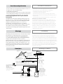
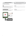
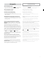
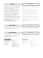
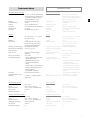
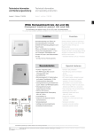
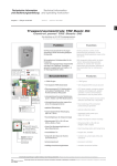
Technische Information und Bedienungsanleitung Technical information and operating instruction Ausgabe: 7 Gültig ab: 08.01.2010 Version: 7 valid from: 08.01.2010 RWA Treppenraumzentrale TRZ Basic 2A SHE control panel TRZ Basic 2A Für Rauchabzug und tägliche Lüftung, für 24 V DC Linear- und Kettenantriebe For smoke heat extraction and daily ventilation for 24 V DC linear drives and chain motors TRZ Basic 2A Steuerplatine Control board RWA-Reset SHE Reset Steckbrücken / Jumper J1 Lüftungstaster “Sonderfunktion” J1 Vent switch “special function” J2 Lüftungszeitautomatik J2 Automatic control ventilation time Stiftleiste für Erweiterungen Pin ledge for extensions Anzeige / Display OK Betrieb OK Operating ok RWA Auf SHE open Störung Malfunction ! Funktion Function Rauchabzugsanlage, vorzugsweise für elektromotorisch zu öffnende Treppenräume. Zum Öffnen der Rauchabzugsklappen im Brandfall. Schließen der Rauchabzugsklappen durch Zu-Funktion der angeschlossenen RWA-Bedienstelle. Öffnen und Schließen für die tägliche Lüftung. Rauchabzugsklappen* in Form von Lichtkuppeln, Dachklappen oder Fenstern mit Linear- oder Kettenantrieben 24 V DC. * (im folg. Text kurz Fenster genannt). Smoke extraction system preferably for eletromechanical openings in stairways. Opening of the smoke vent flaps in case of fire. Closing of the smoke vent flaps via closed-function of the connected SHE manual call point. Opening and closing for daily ventilation. Smoke vent flaps* as dome lights, folding skylights or windows with 24 V DC linear drives or chain motors. * (hereafter referred to only as “windows”). Besonderheiten Special features • Funktion “Tägliches Lüften” • 1 RWA-Gruppe (RG) und 1 Lüftungsgruppe (LG) • Stromversorgung 24 V, Notstromakkus und Ladeteil, Parallelbetrieb, 72 Std. Funktionserhalt bei Netzausfall • Leitungsüberwachung der Melderkreise (autom. Melder und RWA-Bedienstellen) • Leitungsüberwachung der angeschlossenen Antriebe • einstellbare Hubbegrenzung • zuschaltbare Lüftungsautomatik, Schließung nach 10 Min. • optische Störmeldung • separat abgesicherter Netzeingang 230 V AC / 50 Hz • alle Ausgänge kurzschlußsicher • temperaturgeführte Akkuladespannung • Kunststoffgehäuse für Aufputzmontage • Abmessungen 220 x 145 x 85 mm (Höhe x Breite x Tiefe) • Unter-Putz Montagemöglichkeit mit Wand-Blendrahmen • verschließbare Tür • entspricht dem Stand der Technik (normenkonform) • prozessorgesteuert • erweiterbar durch optionale Zusatz module • TÜV-Bauart geprüft • function “daily ventilation” • 1 SHE group and 1 ventilation group • 24 V power supply, emergency power batteries and charging unit, parallel operation, 72 hours of functioning guaranteed in case of power failure • line monitoring of alarm circuits (autom. detectors and SHE man. call points) • line monitoring of the connected drives • adjustable extraction limit • adjustable automatic ventilation, closing after 10 min. • optical malfunction alarm • separately fused power input 230 V AC / 50 Hz • all outputs protected against shortcircuit • temperature controlled battery charged voltage • dimensions 220 x 145 x 85 mm (height x width x depth) • flush mounting option with facing frame • hinged door, lockable • conforms to current state-of-the-arts standards • processor controlled • extension capabilities due to optional available plug-in modules • TÜV type approved Diese Bedienungsanleitung für späteren Gebrauch bzw. Wartung aufbewahren. Please keep these operating instruction for future reference and maintance. Datei: Änderungen Ti_TRZ_Basic_2A_dt_engl.indd Art.Nr. 24999988 dienen dem technischen Fortschritt und bleiben vorbehalten. Abbildungen unverbindlich. Subject to technical modifications. Diagram is not binding. Sicherheitshinweise Sicherheitshinweise, die Sie unbedingt beachten müssen, werden durch besondere Zeichen hervorgehoben. Safety instructions Please observe the following safety instructions which are emphasized by special symbols. Vorsicht: Gefahr für Personen durch elektrischen Strom. Achtung: Nichtbeachtung führt zur Zerstörung Gefährdung für Material durch falsche Handhabung. Warnung: Gefährdung für Personen durch Gefahren aus dem Gerätebetrieb. Quetsch- und Klemmgefahr. INFO Caution: Danger to persons due to electricity. Warning: Non-observance leads to destruction. Danger to material due to incorrect handling. Attention: Danger to persons due to risks arising from the operation of the equipment. Danger of crushing/ trapping. INFO Warnung 230 V AC: Gefährliche Spannung. Kann Tod, schwere Körperverletzung Warning 230 V AC: Dangerous voltage. Can cause death, serious injury or considera- oder erheblichen Sachschaden verursachen. Trennen Sie das Gerät allpolig von der ble material damage. Disconnect the equipment from the power supply at all poles Versorgungsspannung bevor Sie es öffnen, montieren oder den Aufbau verändern. before opening, assembling or carrying out any structural alterations. Observe VDE VDE 0100 für 230 V Netzanschluss beachten. 0100 for 230 V power connection. Beachten Sie bei der Montage und Bedienung: Das Fenster schließt automatisch. Please observe the following for assembly and operation: the window closes automa- Beim Schließen und Öffnen stoppt der Antrieb über die Lastabschaltung. Die entspre- tically. When opening and closing, the drive unit is stopped by the power cut-off. The chende Druckkraft entnehmen Sie bitte den technischen Daten. Die Druckkraft reicht corresponding pressure force is listed in the technical data. Take care - the pressure aber auf jeden Fall aus bei Unachtsamkeit Finger zu zerquetschen. Bei der Montage force is high enough to crush your fingers. During assembly and operation, do not und Bedienung nicht in den Fensterfalz und in den laufenden Antrieb greifen! interfere with the window gap or the travelling drive! Danger of crushing/trapping! Quetsch- und Klemmgefahr! Operating instructions: for professional assembly, installation and appropriate mainteBedienungsanleitung für die fachgerechte Montage, Installation und angemessene nance by trained, qualified and safety-conscious electricians and/or skilled staff with Wartung durch den geschulten, sachkundigen und sicherheitsbewussten Elektro- knowledge of electrical equipment installation. Installateur und / oder Fachpersonal mit Kenntnissen der elektrischen Geräteinstal- Read and observe the information contained in these operating instructions and re- lation. Lesen und Beachten Sie die Angaben in dieser Bedienungsanleitung und spect the order of procedure stated therein. Please keep these operating instructions halten Sie die vorgegebene Reihenfolge ein. Diese Bedienungsanleitung für späteren for future reference and maintenance. Reliable operation and the prevention of dama- Gebrauch / Wartung aufbewahren. Ein zuverlässiger Betrieb und ein Vermeiden von ge and risks are only granted if the equipment is assembled carefully and the settings Schäden und Gefahren ist nur bei sorgfältiger Montage und Einstellung nach dieser are carried out according to these instructions and to the operating instructions of the Anleitung gegeben. Bitte beachten Sie genau die Anschlussbelegung, die minimalen drives. Please observe the exact terminal assignment, the minimum and maximum und maximalen Leistungsdaten (siehe technischen Daten) und die Installationshin- power ratings (see technical data) and the installation instructions. weise. Application range: Exclusively for the automatic opening and closing of the stated Anwendungsbereich: ausschließlich für automatisches Öffnen und Schließen der types of windows. For further application, please contact the manufacturer. It would angegebenen Fensterformen. Weitere Anwendungen im Werk erfragen. be beyond the scope of these safety instructions to list all the valide regulations and Es würde den Rahmen dieser Bedienungsanleitung sprengen, alle gültigen Bestim- guidelines. Always make sure that your system corresponds to the valid regulations. mungen und Richtlinien aufzulisten. Prüfen Sie immer, ob Ihre Anlage den gültigen Pay particular attention to: the aperture cross-section of the window, the opening Bestimmungen entspricht. Besondere Beachtung finden dabei: Öffnungsquerschnitt time and opening speed, the temperature resistance of the cables and equipment, des Fensters, Öffnungszeit und Öffnungsgeschwindigkeit, Temperaturbeständigkeit cross-sections of the cables in relation to the cable lengths and power consumption. von Kabel und Geräten. Benötigtes Befestigungsmaterial ist mit dem Baukörper und Required mounting material is to be adapted to the frame and the corresponding der entsprechenden Belastung abzustimmen und, wenn nötig, zu ergänzen. Ein even- load and is to be completed, if necessary. Any supplied mounting material is only part tuell mitgeliefertes Befestigungsmaterial entspricht nur einem Teil der Erfordernisse. of the required amount. Wartungsarbeiten: Werden die Geräte in Rauch- und Wärmeabzugsanlagen (kurz Maintenance works: If the equipment is employed in smoke heat extraction systems RWA) eingesetzt, müssen sie mindestens einmal jährlich geprüft, gewartet und ggf. (in short SHE), they must be checked, serviced and, if required, repaired at least once instand gesetzt werden. Bei reinen Lüftungsanlagen ist dies auch zu empfehlen. per year. This is also recommended for pure ventilation systems. Die Geräte von Verunreinigungen befreien. Befestigungs- und Klemmschrauben auf Free the equipment from any contamination. Check the tightness of fixing and clam- festen Sitz prüfen. Die Geräte durch Probelauf testen. Das Motorgetriebe ist war- ping screws. Test the equipment by trial run. tungsfrei. Defekte Geräte dürfen nur in unserem Werk instand gesetzt werden. Es sind The gear system is maintenance free. Defective equipment must only be repaired in nur Original-Ersatzteile einzusetzen. Die Betriebsbereitschaft ist regelmäßig zu prüfen. our factory. Only original spare parts are to be used. The readiness for operation has Ein Wartungsvertrag ist empfehlenswert. Alle serienmäßig mit der RWA-Steuerzentrale to be checked regularly. For this purpose a service contract is recommended. gelieferten Akkus bedürfen einer regelmäßigen Kontrolle im Rahmen 2 Sicherheitshinweise Safety instructions der Wartung und sind nach der vorgeschriebenen Betriebszeit (ca. 4 Jahre) aus- All batteries provided with the SHE control panel need to be regularly checked as zutauschen. Bei der Entsorgung der verwendeten Gefahrstoffe - z. B. Akkus - part of the maintenance programme and have to be replaced after their specified Gesetze beachten. service life (approx. 4 years). Please observe the legal requirements when disposing of hazardous material - e.g. batteries. Leitungsverlegung und elektrischer Anschluss nur durch zugelassene Elektrofirma. Netzzuleitungen 230 V AC separat bauseits absichern. Netzzuleitungen bis an Routing of cables and electrical connections only to be done by a qualified electri- die Netzklemme ummantelt lassen. Bei der Installation DIN- und VDE-Vorschriften cian. Power supply leads 230 V AC to be fused separately by the customer. Keep beachten, VDE 0100 Errichten von Starkstromanlagen bis 1000 V, VDE 0815 Instal- power supply leads sheathed until the mains terminal. lationskabel und -leitungen, VDE 0833 Gefahrenmeldeanlagen für Brand, Einbruch DIN and VDE regulations to be observed for the installation: VDE 0100 Setting up und Überfall. Kabeltypen ggf. mit den örtlichen Abnahmebehörden, Energieversor- of high voltage installations up to 1000 V. VDE 0815 Installation cables and wires. gungsunternehmen, Brandschutzbehörden oder Berufsgenossenschaften festlegen. VDE 0833 Alarm systems for fire, break-in and burglary. Alle Kleinspannungsleitungen (24 V DC) getrennt von Starkstromleitungen verlegen. Cable types to be agreed with local inspection authorities, power utilities, fire Flexible Leitungen dürfen nicht eingeputzt werden. Frei hängende Leitungen mit protection authority and the professional associations. Zugentlastung versehen. Die Leitungen müssen so verlegt sein, dass sie im Betrieb All low voltage cables (24 V DC) to be installed separately from high voltage cables. weder abgeschert, verdreht noch abgeknickt werden. Abzweigdosen müssen für Flexible cables must not be plastered in. Provide tension relief for freely suspended Wartungsarbeiten zugänglich sein. Die Kabelarten, -längen und -querschnitte gemäß cables. The cables must be installed in such a way that they cannot be sheared den technischen Angaben ausführen. off, twisted or bent off during operation. Junction boxes must be accessible for maintenance work. Adhere to the type of cables, cable lengths and cross-sections Vor jeder Wartungsarbeit oder Veränderung des Aufbaus sind as stated in the technical information. die Netzspannung und Akkus allpolig abzuklemmen. Gegen unbeab- sichtigtes Wiedereinschalten ist die Anlage abzusichern. Elektrische Steuerungen The supply voltage and the batteries are to be disconnected at all müssen stromlos sein, bevor Sie Teile entnehmen oder dazusetzen (Netzspannung und Akkus abklemmen). must be protected against unintentional re-starting. Electrical controls must be poles before maintenance work or structural alterations. The system voltage free before extension modules are taken off or added (disconnect mains Nach der Installation und jeder Veränderung der Anlage alle Funktionen durch voltage and batteries). Probelauf überprüfen. After installation and any changes to the system check all functions by a trial run. Beachten Sie bei der Montage und Bedienung: Die Fenster schließen automatisch. Quetsch- und Scherstellen zwischen Fensterflügel und Rahmen, Lichtkuppeln und During assembly and operation, please observe: the windows may close automati- Aufsetzkranz müssen bis zu einer Höhe von 2,5 m durch Einrichtungen gesichert cally. Potential crushing and cutting points between the casement and the window sein, die bei Berührung oder Unterbrechung durch eine Person, die Bewegung zum frame, dome lights and support frame must be secured up to a height of 2.5 m Stillstand bringen (Richtlinie für kraftbetätigte Fenster, Türen und Tore der Berufsge- by safety equipment, which if touched or interrupted by a person will immediately nossenschaften). stop the movement (guideline for power operated windows, doors and gates of the professional association). Achtung! Die Antriebe und Bedienstellen niemals an 230 V anschließen! Sie sind für 24 V gebaut! Lebensgefahr! Warning! Never connect the drives and call points to 230 V! They are built for 24 V! Risk of death! Bei Anwendungen am Kippfenster muss eine Kippfang-Sicherungsschere eingebaut werden. Sie verhindert Schäden, die bei unsachgemäßer Montage und Handhabung For applications: Tilt windows: A scissor-type safety catch is to be installed. It auftreten können. Bitte beachten: die Kippfang-Sicherungsschere muss mit dem prevents damage caused by incorrect assembly and handling. Please observe: the Öffnungshub des Antriebes abgestimmt sein. Das heißt, die Öffnungsweite der scissor-type safety catch must be adapted to the opening stroke of the drive unit, Kippfang-Sicherungsschere muss, um eine Blockade zu vermeiden, größer als der i.e. that the opening of the safety catch must be larger than the drive unit stroke in Antriebshub sein. Siehe Richtlinie für kraftbetätigte Fenster, Türen und Tore. Schützen order to prevent blocking. See guideline for power-operated windows, doors and Sie alle Aggregate dauerhaft vor Wasser und Schmutz. gates. Provide all aggregates with durable protection against water and dirt! Achtung: Die Antriebe nur mit Steuerungen vom gleichen Hersteller betreiben. Bei Verwendung von Fremdfabrikaten keine Attention: The control must only be operated with drives made by the same manufacturer. No liability will be accepted and no guarantee nor Haftung, Garantie- und Serviceleistungen. Die Montage und Installation muss sach- service is granted if products of outside manufacturers are used. Assembly and gemäß, sicherheitsbewusst und nach Angaben der Bedienungsanleitung erfolgen. installation must be carried out properly, according to the information of the operat- Werden Ersatzteile, Ausbauteile oder Erweiterungen benötigt bzw. gewünscht, ing instructions paying particular attention to safety aspects. If spare parts, disman- ausschließlich Original-Ersatzteile verwenden. tled parts or extension components are required or desired, only use original spare parts. Herstellererklärung: Die Geräte sind gemäß der europäischen Richtlinien geprüft und hergestellt. Eine entsprechende Herstellererklärung liegt vor. Sie dürfen die Geräte Manufacturer’s declaration nur dann betreiben, wenn für das Gesamtsystem eine Konformitätserklärung vorliegt. The equipment has been manufactured and tested according to the European regulations. A corresponding manufacturer’s declaration has been submitted. You may only operate the system if a Declaration of Conformity exists for the entire system. 3 Funktionsbeschreibung Description of operating Manuelle Auslösung bei Feuer/Brand/Alarm Rauchabzug / Fenster öffnen rote AUF-Taste in einer RWA-Bedienstelle drücken, Fenster werden vollständig geöffnet, rote LED-Anzeige - RWA ausgelöst - leuchtet in allen RWA-Bedienstellen, die Lüftungsfunktion ist außer Betrieb. Manual activation in case of fire/smoke/alarm Smoke heat extraction / opening windows Press the red OPEN switch at a SHE manual call point, the windows open completely, the red LED display - SHE activated - is shining at all SHE manual call points, the ventilation function is out of order. Rauchabzug / Fenster schließen ZU-Taste in einer RWA-Bedienstelle drücken, Fenster schließen, die rote LED-Anzeige - RWA ausgelöst - erlischt in allen RWA-Bedienstellen, Lüftungsfunktion ist wieder in Betrieb. Smoke heat extraction / closing windows Press the switch “closed” at a SHE manual call point, the windows are closing, the red LED display - SHE activated goes out at all SHE manual call points, the ventilation function is working again. Hinweis: es erfolgt kein Zurücksetzen (Reset) der angeschlossenen und ausgelösten automatischen Melder! Automatische Auslösung bei Feuer/Brand/Alarm nur wenn automatische Melder angeschlossen sind. Rauchabzug / Fenster öffnen Rauch erreicht die automatischen Melder, Fenster werden vollständig geöffnet, rote Anzeige im automatischen Melder - RWA ausgelöst - leuchtet in allen leuchtet, rote LED-Anzeige RWA-Bedienstellen, die Lüftungsfunktion ist außer Betrieb. Rauchabzug / Fenster schließen ZU-Taste in einer RWA-Bedienstelle drücken, Fenster schließen, die rote LED-Anzeige - RWA ausgelöst - erlischt in allen RWA-Bedienstellen, gelbe LED - Störung - blinkt. Hinweis: es erfolgt kein Zurücksetzen (Reset) der angeschlossenen und ausgelösten automatischen Melder! Zurücksetzen der automatischen Melder Automatische Melder von Rauch befreien (durch Ausblasen bzw. bei starker Verschmutzung ersetzen). Taste RWA-RESET in der Steuerzentrale (auf Platine) drücken, alle angeschlossenen automatischen Melder werden zurückgesetzt (Reset), Fenster schließen, rote Anzeige im automatischen Melder erlischt, die rote LED-Anzeige - RWA ausgelöst - erlischt in allen RWA-Bedienstellen, die gelbe LED-Anzeige - Störung - erlischt, die Lüftungsfunktion ist wieder in Betrieb. Tägliches Lüften nur wenn Lüftungstaster angeschlossen sind. Fenster öffnen am Lüftungstaster AUF-Taste kurz drücken, Fenster wird vollständig geöffnet. (Unterbrechen des Öffnungsvorgangs durch kurzes gemeinsames Antippen beider Tasten (Auf und Zu) = STOP oder durch Taste Stop je nach Lüftungstaster). Fenster schließen am Lüftungstaster ZU-Taste kurz drücken, Fenster schließen vollständig. (Unterbrechen des Schließvorgangs durch kurzes gemeinsames Antippen beider Tasten (Auf und Zu) = STOP oder durch Taste Stop je nach Lüftungstaster). Bei Netz- oder Akkuausfall schließen die Fenster sofort. 4 Note: there is no reset of the connected and activated automatic detectors! Automatic activation in case of fire/smoke/alarm if automatic detectors are connected only. Smoke heat extraction / opening windows Smoke reaches the automatic detectors, the windows are opened completely, the red display in the automatic detector is shining, the - SHE activated - is shining at all SHE manual red LED display call points, the ventilation function is out of order. Smoke heat extraction / closing windows Press the switch “closed” at a SHE manual call point, the windows are closing, the red LED display - SHE activated goes out at all SHE manual call points, the yellow LED display - malfunction - flashes. Note: there is no reset of the connected and activated automatic detectors! Reset of automatic detectors Set the automatic detectors free from smoke by blowing out or replace them in case of heavy soiling. Press the RESET switch on the basic circuit control board of the control panel, the windows are closing, the red display in the automatic detectors goes out, the red LED display - SHE activated - goes out at all SHE manual call points, the yellow LED display - malfunction - goes out, the ventilation function is working again. Daily ventilation If vent switches are connected only. Opening windows Press the switch “open” at the vent switch, the windows open completely. (Interruption of the opening by pressing both switches together (Open and Closed) = STOP or by Stop switch depending on vent switch). Closing windows Press the switch “closed” at the vent switch, the windows close completlely. (Interruption of the opening by pressing both switches together (Open and Closed) = STOP or by Stop switch depending on vent switch). In case of mains or battery failure, the windows close immediately. Funktionsbeschreibung Description of operating Schließen mit 10 Min. Automatik ist die 10 Min. Automatik aktiv (siehe Inbetriebnahme), schließen die Fenster selbständig nach 10 Min., bei Netz- oder Akkuausfall schließen die Fenster sofort. Automatic ventilation control If activated (see putting into operation), the windows are closing automatically after 10 min., in case of mains or battery failure, the windows close immediately. Hubbegrenzung (über Laufzeit) Aktivierung Jumper (J1) darf nicht gesteckt sein, die Fenster schließen! Die Tasten Auf und Zu (STOP) am Lüftungstaster drücken und solange gedrückt halten bis ein schnelles Blinken der Auf-Anzeige erscheint. Innerhalb der nächsten 10 Sek. (sonst Hubweitenbegrenzung inaktiv!) mit der Taste Auf anfahren und bei gewünschter Öffnungsposition mit der Taste Zu den Antrieb stoppen. Erfolgt innerhalb von 10 Sek. kein weiterer Tastendruck ist die Hubweitenbegrenzung aktiviert, der Lernmodus ist beendet. Extraction limit (by operating time) To activate Jumper (J1) may not be setted, close the windows! Press the switches “open” and “closed” (STOP) at the vent switch as long as the display “open” is flashing fast. Open the motor with the switch “open” up to the position required within the next 10 sec. (otherwise the extraction limit is not activated!) and stop the motor in this position with the switch “closed”. If no other switch is pressed within the next 10 sec. the extraction limit is activated, the learning phase is finished. Wenn die Hubweitenbegrenzung aktiv ist und der Antrieb nicht zugefahren ist, wird die Aktivierung durch Doppelblinken der AufAnzeige signalisiert. If the extraction limit is activated and the actuator is not closed, it is signalised by double flashing at the “open” display. Hinweis: Nach RWA-Auslösung und erfolgter Zurücksetzung (Reset) ist die Hubweitenbegrenzung und somit die Lüftungsfunktion für 3 Min. gesperrt. Note: the extraction limit and the ventilation function is cut off for 3 min. after SHE activation and following reset. Deaktivierung Die Tasten Auf und Zu (STOP) am Lüftungstaster drücken und gedrückt halten bis ein schnelles Blinken der Auf-Anzeige erscheint. Innerhalb der nächsten 10 Sek. keine Bedienung der Anlage bis das Blinken erlischt. Die Hubweitenbegrenzung ist nun inaktiv. To deactivate Press the switches “open” and “closed” (STOP) at the vent switch as long as the display “open” is flashing fast. If no other switch is pressed within the next 10 sec. until the flashing goes out the extraction limit is deactivated. Hinweis: bei Netz- oder Akkuausfall oder bei RWAAuslösung ist die Lüftungsfunktion außer Betrieb. Bei Netz- oder Akkuausfall schließen die Fenster sofort. LED-Anzeigen In der Steuerzentrale und in den RWA-Bedienstellen. Note: in case of mains or battery failure or SHE activation the function is out of order. In case of mains or battery failure, the windows close immediately. LED display In the SHE control panel and SHE manual call points. Die grüne LED-Anzeige OK - Betrieb OK - leuchtet. Sie erlischt bei: - Netz- oder Akkuausfall - Störung der Leitungsüberwachung zu den Antrieben, RWABedienstellen oder automatischen Meldern. The green LED display OK - operating OK - is shining. It goes out in case of: - mains or battery failure - malfunction of the line monitoring of the connected drives, automatic detectors or SHE manual call points. Die gelbe LED-Anzeige The yellow LED display - Störung - blinkt: eine Störung steht an, Leitungsanschluss defekt, Netz und/oder Akku defekt. Bei jeglicher Störmeldung muss unbedingt sofort die Störung beseitigt werden. Eine reibungslose Funktion der Anlage ist nicht mehr gewährleistet. Die rote LED-Anzeige - RWA ausgelöst - leuchtet: nach Drücken der AUF-Taste in einer RWA-Bedienstelle bzw. im Bedienfeld der Steuerzentrale und nach dem Auslösen durch automatische Melder. - malfunction - is flashing in case of: malfunction, cable connection defective, mains and/or battery failure. If any malfunction is indicated the malfunction has to be eleminated immediately. The perfect function of the system is not longer guaranteed. The red LED display - SHE activation - is shining in case of: manual or automatic SHE activation. 5 Anschlussmöglichkeiten Possible connections - 24 V DC Antriebe mit einer Gesamt-Stromaufnahme von max. 3 A mit eigener Last- oder mit Endabschaltung - 10 RWA-Bedienstellen RBH/3A... - 6 automatische Melder in 2-Leiter-Technik, optische Rauchmelder und/oder Wärmedifferential-Melder und/oder Wärmemaximal-Melder - 10 externe Lüftungstaster AUF/STOP/ZU (z. B.: Typ LTA 25) Erweiterungsmöglichkeiten über separat erhältliche Zusatzmodule TRZ/WRMAS Basic (Wind-Regen-Meldung-Alarm-Störung). Zum Anschluss von max. 1 Wind-/ Regenmelder (Typ WRM 24V) oder Regensensor (Typ RS) und zur pot.-freien Meldung Alarm (RWAausgelöst) und Sammelstörung (max. 24 V / max. 0,5 A). TRZ/RBH-Basic (Zusatzplatine RWA-Taster, Typ RBH3A). Zur Nachrüstung einer RWA-Bedienstelle, integriert in die Fronttür der TRZ Basic. Funktionsumfang gemäß einer RWA-Bedienstelle RBH/3A. Klemmbelegungen und Bedienungshinweise, siehe “Zusatzmodule”. - linear drives 24 V DC with integrated electronic power cut-off, or chain motors 24 V DC with limit switches, overall power consumption of all motors connected: max. 3 A - 10 SHE manual call points RBH/3A... - 6 automatic detectors with 2-wire-technology, optical smoke detectors and/or detectors of heat differential and/or detectors of maximum heat - 10 external vent switches Open/Stop/Closed (e.g. type LTA 25) Extensions via optional modules TRZ/WRMAS Basic (Wind rain detector alarm malfunction). To connect max. 1 wind/rain detector (type WRM 24V) or rain sensor (type RS) and potential free trans-mission of the signals Alarm (SHE activated) and malfunction collection (max. 24 V / max. 0.5 A). SHE manual call point TRZ/RBH-Basic for SHE control panel TRZ Basic. Additional module for installation into the front door of the TRZ Basic. Terminal assignment and installation please see “additional module optional”. Montage Assembly Die Montage der Steuerzentrale muss in trockenem Raum erfolgen. Die Montageorte der RWA-Bedienstellen und Lüftungstaster müssen gut sichtbar und erreichbar sein (RWA-Bedienstelle = 1,4 m über Fußbodenoberkante). Nicht hinter Wandvorsprüngen, Türflügeln oder von Baukörpern verdeckt montieren. Steuerzentrale öffnen und an den vorgegebenen 4 Bohrungen am Baukörper befestigen. Für geeignetes Befestigungsmaterial ist zu sorgen. Bedienelemente, Antriebe, Anschlussdosen (max. 1,2 m zum Antrieb) und automatische Melder nach deren beiliegenden Bedienungsanleitungen montieren. Entsprechende Vorschriften (siehe Seite 2) einhalten. The SHE control panel has to be installed in a dry room. The assembly places for the SHE manual call points and the vent switches must be well visible and accessible (SHE call point = 1.4 m over the top edge of the floor). Do not assemble behind wall projections, door casements or hide behind construction elements. Open the SHE control panel and fix it at the specified 4 bore-holes to the construction body. Make sure to provide appropriate material for the fixations. Assembly of control elements, drives, junction boxes (max.1.2 m to the drive) and automatic detectors according to their joint operating instructions. Please observe applicable regulations (see Page 2). Kabelplan Routing of cables Dachfenster Skylight Lichtkuppel Dome light Letzte Anschlussdose mit eingebauten Überwachungsdioden Last junction box with integrated monitoring diodes Linearantrieb Linear drive NYM-O 3 x 1,5 mm² Max. Gesamtleitungslänge 50 m max. total cable length 50 m letzter autom. Melder mit Endwiderstand, max. 6 Stück last autom. detector with end resistor, max. 6 pieces Nur mit Zusatzmodul: Wind/Regenmelder WRM 24V oder Regenmelder RM 24V, max. 1 Stück. Only with additional modules wind/rain detector WRM 24V or rain detector RM 24V , max. 1 piece. Abstand max. 1,2 m Distance max. 1.2 m Anschlussdose Junction box J-Y(ST)Y 2 x 2 x 0,8 24 V DC / 100 mA J-Y(ST)Y 2 x 2 x 0,8 mm Leitungslänge bis 150 m J-Y(ST)Y 4 x 2 x 0,8 mm Leitungslänge bis 300 m (Adern doppelt auflegen) J-Y(ST)Y 2 x 2 x 0,8 mm cable length up to 150 m J-Y(ST)Y 4 x 2 x 0,8 mm cable length up to 300 m (double the cores) J-Y(ST)Y 2 x 2 x 0,8 J-Y(ST)Y 3 x 2 x 0,8 NYM-O 3 x 1,5 mm² max. zulässige Länge: bei 1 A = 100 m bei 2 A = 50 m bei 3 A = 25 m NYM-O 3 x 1.5 mm² max. permitted length: at 1 A = 100 m at 2 A = 50 m at 3 A = 25 m Rauchabzug Smoke heat extraction Lüftung/VENT STOP J-Y(ST)Y 2 x 2 x 0,8 max. Gesamtleitungslänge 50 m max. total cable length 50 m J-Y(ST)Y 3 x 2 x 0,8 Rauchabzug Smoke heat extraction Lüftung/VENT Rauchabzug Smoke heat extraction STOP Lüftungstaster, max. 10 Stück Vent switch, max. 10 pieces 6 letzte RWA-Bedienstelle mit Endwiderstand, max. 10 Stück Steuerzentrale last SHE manual call point, Control panel max. 10 pieces Netz 230 V/50Hz NYM-I 3 x 1,5 mm² Separat abschaltbaren Stromkreis vorsehen. Vor unbeabsichtigtem Abschalten sichern. Mains 230 V/50Hz NYM-I 3 x 1.5 mm² provide a separately disconnetible circuit. Secure against unintentinal switching-off. Kabelplan Routing of cables Für die Unter-Putz-Verlegung können ggf. die angeg. Leitungstypen verwendet werden. Dieses ist jedoch mit der Bauleitung oder, falls erforderlich, mit der örtlichen Brandschutzbehörde abzustimmen. Die angegebenen Kabelquerschnitte dürfen nicht verringert werden. Sie sind für eine Umgebungstemperatur von 20 °C angegeben. Für höhere Temperaturen, die Querschnitte erhöhen. Für die Auf-Putz-Verlegung empfehlen wir Brandschutzkabel mit Funktionserhalt E90 (E30) nach DIN 4112. Bei E90 (E30) müssen die Kabelquerschnitte entspr. den Vorschriften des Herstellers angepasst werden. Alle Leitungen zu der Steuerzentrale (außer Netzzuleitung) führen 24 V DC und müssen getrennt von der Netzzuleitung verlegt werden. Bei der Leitungsverlegung sind die entsprechenden VDE-Richtlinien zu beachten. The specified types of cables can possibly be used for flush mounting. This is, however, to be agreed with the site management or, if necessary, with the local fire protection authorities. The stated cable cross-sections must not be reduced. They are specified for an ambient temperature of 20 °C. For higher temperatures, increase the cross-sections. We recommend for surface mounting fireproof cables with maintain functin E90 (E30) according to DIN 4112. For E90 (E30) the cable cross sections must be adapted to conform with the manufacturer’s specifications. All cables to the control panel (apart from the mains cable) carry 24 V DC and must be routed separetely from the mains cable. The corresponding VDE regulations are to be observed when routing the cables. Installation Routing of cables Anschlussleitungen von oben in das Gehäuse der Steuerzentrale führen. Anschlussleitungen nach Klemmplan einklemmen, hierbei auf richtigen Anschluss achten. Falsches Einklemmen sowie Nummern- oder Farbendreher können zu Fehlfunktionen der Steuerzentrale oder der externen Elemente führen. ein Lüftungstaster mit Sichtanzeige LTA 25 one vent switch with visual display LTA 25 LED 1 ZU 2 closed 2 AUF 3 Open 3 GEM 4 together 4 ein Antrieb gesamte Stromaufnahme max. 3 A one drive total power consumption max. 3 A Motor = Anschlussdose/Junction box braun brown blau blue AUF / OPEN Route the connecting cables into the control panel housing at the top. Connect all connecting cables according to the wiring diagram and make sure that they are correctly connected. Incorrected connections or figure or colour mix-ups can lead to incorrect function of the control panel or of the external components. ein Lüftungstaster Auf / Zu gemeinsam = Stop one vent switch open / closed together = Stop ein autom. Melder one autom. detector eine RWA-Bedienstelle RBH/3A one SHE man. call point RBH/3A OK Jumpereinstellung für die TRZ Basic 2A/UP auf der Rückseite des Tasters. Jumper setting for the TRZ Basic 2A/UP at the rear of the switch. rote/red LED Endwiderstand 10k End resistor 10k ! 6 1 2 3 4 5 + ZU / CLOSED AUF / OPEN 4 5 1 8 6 3 2 19 18 SSD... UTD... oder/or MSD... STOP O 2 8 9 3 S O P S 10 11 5 4 AM/.... 1+ 2 12 13 14 15 16 12 18 19 LED rot/LED red LED gelb/LED yellow Anschlussklemmen in der Steuerzentrale Terminals in the control panel 17 Taste AUF/switch open 15 16 Taste ZU/switch closed 14 LED grün/LED green 12 13 GND RWA-Bedienstelle/SHE man. call point autom. Melder/autom. detector 11 Taste AUF/switch open Taste ZU/switch closed 9 10 LED “Vent open” 8 Masse / GND 3 17 Keine RWA-Bedienstelle und/oder autom. Melder, Linienabschluss (W) in der Zentrale aufklemmen. No SHE man. call point and/or autom. detector, connect line termination (W) in the control panel. Lüftungstaster Vent switch LED “Lüftung Auf”/ 2 Überwachung/ Monitoring 1 Motor - Netzleiter/phase cond. PE Motor 24 V DC max. 3 A Motor + N Schutzleiter/ PE conductor L Neutralleiter/neutral cond. Netz/Mains 230 V/50Hz 18 19 17 18 19 autom. detector - 1 P ZU / CLOSED 1 2 3 autom. Melder + 4 7 Installation Installation Leitungsüberwachung: Überwachungsdioden in der letzten oder einzigen Anschlussdose einklemmen. Line monitoring: monitor diodes to connect in the last or in the unique junction box. mehrere Antriebe, gesamte Stromaufnahme max. 3 A several drives total power consumption max. 3 A Linienabschluss: im letzten oder einzigen autom. Melder Endwiderstand 10k (W) einklemmen. Line termination: connect provided 10k end resistor (W) in the last or unique automatic detector. Linienabschluss: in der letzten oder einzigen RWA-Bedienstelle beiliegenden Endwiderstand 10k (W) einklemmen. Line termination: connect provided 10k end resistor (W) in the last or unique SHE manual call point. mehrere Lüftungstaster mit Sichtanzeige LTA 25 several vent switches with visual display LTA 25 mehrere Lüftungstaster Auf / Zu gemeinsam = Stop several vent switches open / closed together = Stop mehrere autom. Melder several autom. detectors mehrere RWA-Bedienstellen RBH/3A several SHE man. call points RBH/3A Sockel USB... 4 2 1 3 O P S O P S Anschlussdose Junction box 1. Melder 1. detector braun Motor brown blau = blue 5 1 4 2 1 3 O P S O P 8 4 + 3 2 1 8 9 3 O 10 11 P S 8 10 O P S 11 5 1 12 13 8 4 14 15 16 12 17 GND LED rot/LED red LED gelb/LED yellow Anschlussklemmen in der Steuerzentrale Terminals in the control panel 17 Taste AUF/switch open 15 16 Taste ZU/switch closed 14 LED grün/LED green 12 13 Legende RBH/3A Legend RBH/3A Taster RWA-AUF Switch SHE open Taster RWA-ZU Switch SHE closed LED RWA-AUF LED SHE open LED Betrieb OK LED operating ok LED Störung LED malfunction OK Überwachungsdioden Monitoring diodes 1 2 24 V DC - + 24 V DC + - 3 Polung der Motorspannung für Auf/Zu Polarity of the motor voltage for open/close 8 18 19 18 19 RWA-Bedienstelle/SHE man. call point autom. Melder/autom. detector 11 Taste AUF/switch open LED “Vent open” 9 10 Taste ZU/switch closed 8 Masse / GND 3 17 Keine RWA-Bedienstelle und/oder autom. Melder, Linienabschluss (W) in der Zentrale aufklemmen. No SHE man. call point and/or autom. detector, connect line termination (W) in the control panel. Lüftungstaster Vent switch LED “Lüftung Auf”/ 2 Überwachung Monitoring Motor - 1 Motor + Netzleiter/phase cond. Neutralleiter/neutral cond. PE Schutzleiter/ PE conductor N Motor 24 V DC max. 3 A 5 4 AM/... 1+ 2 3 6 18 19 autom. detector - 4 1 2 L SSD... UTD... oder/or MSD... 19 18 S 5 4 AM/... 1+ 2 braun Motor brown blau = blue Netz/Mains 230 V/50Hz 6 1 2 3 4 5 3 6 autom. Melder + letzter Antrieb last drive Base USB... letzter Melder 6 last detector 1 2 3 4 5 Optionale Zusatzmodule Additional modules optional Die Erweiterung mit den Zusatzmodulen TRZ/WRMAS und TRZ/RBH ist optional und gehört nicht zum Lieferumfang der TRZ Basic 2A. Bei Bedarf wenden Sie sich bitte an Ihren Händler. The extension by the additional module TRZ/WRMAS and TRZ/RBH are an option, it is not part of the TRZ Basic 2A standard supply. Please ask your distributor if required. Wind-Regen-Meldung-Alarm-Störung (TRZ/WRMAS-Basic) Folgende Komponenten sind anschließbar: 1 x Anschluss Wind-/Regenmelder WRM 24V oder Regenmelder RM 24V 1 x pot.-freie Weiterleitung Alarm (RWA-Auslösung) 1 x pot.-freie Weiterleitung Sammelstörung, Kontaktbelastung max. 24 V / max. 0,5 A Wind-rain-detection-alarm-malfunction (TRZ/WRMAS-Basic) The following components can be connected: 1 x connection wind/rain detector WRM 24V or rain detector RM 24V 1 x pot.-free transmission Alarm (SHE-activation) 1 x pot.-free transmission collect. malfunction, charge on contact max. 24 V / max. 0.5 A Einbau Zentrale stromlos schalten (Netz und Akku), Platinenabstandshalter auf die Grundplatine aufstecken, Zusatzmodul auf die Erweiterungsleiste aufstecken, gewünschte Anschlüsse herstellen und überprüfen, Stromversorgung wieder herstellen (Netz und Akku). Funktion Wind-/Regenmeldung prüfen Keine RWA- und keine Störmeldung, grüne LED OK Betrieb leuchtet. Taste AUF am Lüftungstaster betätigen, die Antriebe fahren auf. Regensensorfläche des Witterungsmelders befeuchten, die Antriebe fahren zu. Sofern der Lüftungstaster eine Anzeige für AUF besitzt, blinkt diese. Die Lüftungsfunktion ist für die Zeit der Wind- oder Regenmeldung gesperrt. RWA auslösen - die Antriebe müssen während einer Wind- oder Regenmeldung öffnen (RWA hat Vorrang). Zum Testen der Windmeldung muss für ca. 3 Min. ein ständiger Luftstrom am Windrad anliegen (z. B. ein Fön), ansonsten erfolgt die Prüfung wie oben beschrieben. Funktion Alarm (RWA) und Störung prüfen Keine RWA- und keine Störmeldung, grüne LED OK Betrieb leuchtet. RWA auslösen. Schließerkontakt an den Klemmen 4 + 5 schaltet. Die Funktion ist in Ordnung, wenn der Durchgang messbar ist. RWA-ZU (Reset) betätigen, Grundstellung, keine RWAAuslösung und keine Störmeldung. Störmeldung simulieren durch Ziehen der Akkusicherung F3, Auslösung! Sicherung F3 wieder einsetzen, Zentrale wieder in Grundstellung bringen, komplette Inbetriebnahme der TRZ Basic 2A wiederholen. Keine Fehler, Funktion ist in Ordnung, die Anlage ist betriebsbereit. Wind-/Regenmelder Wind/rain detector Installation Disconnect the control panel from power supply (mains and battery), plug the spacer to the principal circuit control board, plug the additional module to the extension ledge, create the desired connections and check, restablish power supply (mains and battery). Check wind/rain detection function No SHE and no malfunction signal, the green LED OK operating is shining. Press the switch Open at the vent switch, the motor opens. Humidify the rain sensor surface of the weather detector the drives are closing. If the vent switch has a display for Open, it flashes. The ventilation function is blocked as long as a wind or rain alarm is pending. Activate SHE - the drives have to open during a pending wind or rain alarm (SHE has priority). To test the wind detection, a permanent air current has to be detected at the wind wheel (hair dryer). Otherwise, procede for the checking as described above. Check Alarm (SHE) and malfunction function No SHE and no malfunction detection, green LED OK - operating - is shinig. Ativate SHE. The closing contact at the terminals 4 + 5 switches. The function is OK if the passage can be measured. Activate SHE Closed (Reset), initial position, no SHE-activation and no malfunction detection. Take of the battery fuse F3 to simulate a malfunction, Activation! Replace fuse F3 back, control panel again in initial position, repeat complete bringing into service of the TRZ Basic 2A. No errors, function is OK, system ready for operation. WRM 24V RM 24V 1 2 A S OE Erweiterungsleiste Extension ledge 4 5 6 7 20 2122 23 TRZ/WRMAS Schließerkontakt Alarm (RWA) Closing contact alarm (SHE) Anschlussklemmen Wind-/Regenmelder Connection terminals wind/rain detector Öffnerkontakt Sammelstörung Opening contact collective malfunction 20 GND 21 24 V DC, 0,1 A 22 GND Melder GND detctor 23 W/R-Signal 9 Optionale Zusatzmodule RWA-Bedienstelle TRZ/RBH-Basic zum Einbau in die Fronttür der TRZ-Basic 2A. SHE manual call point TRZ/RBH-Basic SHE manual call point, integrated in the TRZ Basic 2A front door. Einbau Zentrale stromlos schalten (Netz und Akku), Zusatzmodul auf der Innenseite der Zentralentür montieren, Stecker auf die Erweiterungsleiste der Grundplatine oder - wenn vorhanden - auf die Erweiterungsleiste des Zusatzmoduls TRZ/WRMAS stecken, Stromversorgung wieder herstellen (Netz und Akku). Installation Disconnect power supply (mains and battery), mount additional module at the inside of the control panel door, plug the plug to the extension ledge of the principal circuit control board or, if available, of the add. module TRZ/WRMAS, reconnect power supply (mains and battery). Funktion RWA-Bedienstelle prüfen Gemäß Seite 12 Punkt “RWA-Bedienstellen” verfahren, komplette Inbetriebnahme der TRZ Basic 2A wiederholen, keine Fehler, Funktion ist in Ordnung, die Anlage ist betriebsbereit. Function check Procede as indicated page 12, point “SHE man. call point“, repeat the complete bringing into service of the TRZ Basic 2A, no errors, function OK, system is ready for operation. Grün LED: Betrieb OK green LED: Operating OK OK Rote LED: RWA Auf red LED: SHE-OPEN ! gelb LED: Störung yellow LED: Malfunction Taste für / switch for RWA-ZU (kein Reset) SHE-Close (no reset) RW-Auslösung SHE-activation 10 Additional modules optional Inbetriebnahme und Probelauf Ohne Netzspannung, ohne Akku Alle Teile mechanisch und elektrisch auf feste Verschraubung und auf Beschädigungen prüfen, die Klemmen: Motor und Bedienelemente sowie, falls vorhanden, automatische Melder und Wind-/Regenmelder aufstecken. Batteriesicherung nicht stecken! Mit Netzspannung, mit Akku Netz einschalten. Batteriesicherung einsetzen. Sichtanzeige in der Tür der Steuerzentrale Max. 100 Sek. nach Einsetzen der Batteriesicherung und Einschalten der Netzversorgung kontrollieren: grüne LED OK - Betrieb OK - leuchtet, rote LED - RWA-Auslösung - leuchtet nicht, gelbe LED - Störung - leuchtet nicht. Bei Störung, siehe Kapitel “Störungshilfe” und “Fehlersuche”. Lüftungstaster (sofern vorhanden) Standardfunktion, Steckbrücke J1 nicht gesteckt. Taste AUF betätigen, die Antriebe öffnen die Fenster vollständig bis zur Endstellung, die Anzeige “Lüftung AUF” (sofern vorhanden) leuchtet, während dieses Laufens die Fenster beobachten. Achtung: Auf Kollision der Antriebe mit dem Baukörper achten. Antriebe dürfen in keiner Lage durch den Baukörper behindert werden. Anschlussleitungen der Antriebe prüfen: sie dürfen weder auf Zug noch auf Quetschung belastet werden. Lüftungstaster ZU betätigen, die Antriebe schließen das Fenster. Die Anzeige “Lüftung AUF” erlischt. Während des Laufens STOP drücken (STOP = beide Tasten AUF und ZU gemeinsam, die Antriebe stoppen. Die Anzeige “Lüftung AUF” leuchtet. Lüftungstaster ZU nochmals betätigen, die Antriebe schließen, die Anzeige “Lüftung AUF” erlischt. Die Antriebe schließen die Fenster vollständig bis zur Endstellung, die Anzeige “Lüftung AUF” bleibt erloschen. Achtung: Auch während dieser Bewegung auf Kollision, Zug und Quetschung achten. Lüftung “Sonderfunktion” Geeignet zum Anschluss von Schlüssellüftungstastern, um die Stop-Funktion zu gewährleisten. Steckbrücke J1 ist gesteckt. Taste AUF betätigen, die Fenster öffnen. Um die Antriebe zu stoppen, Taste ZU kurz betätigen. Taste Zu nochmals betätigen, die Antriebe schließen die Fenster. Um die Antriebe zu stoppen, die Taste Auf kurz betätigen. Taste Auf betätigen, die Fenster öffnen. Taste Zu lang betätigen, die Antriebe schließen die Fenster. Taste Auf lang betätigen, die Antriebe öffnen die Fenster. Putting into operation and trial run Without mains voltage and without battery Check all parts mechanically and electrically for fully tightened screw connections and damage, the terminals: plug in connectors for motors and control elements as well as, if available, automatic detectors and wind/rain detectors. Do not plug in the batterie fuse! With mains voltage and battery Switch on mains. Plug in battery fuse. Visual display in the control panel door Max. 100 secs. after after plugging in of the battery fuse and switching on of mains, check: green LED OK - Operation OK - lit up, red LED - SHE activation - not lit up, yellow LED - Malfunction - not lit up. In case of malfunction, see chapter “Troubleshooting” and “Fault finding”. Vent switch (when existing) Standard function, jumper J1 is not plugged. Press switch “open”, the drives open the windows completely up to the end position, the display “ventilation open” (when existing) is shining, observe the windows during this running. Attention: Make sure the drives can move freely at any times without obstruction. Pay attention to potential collision, tension and crushing during this movement, too. Check the connection cables of the drives: they must not be strained by tension or crushing. Press the vent switch “closed”, the drives close the windows. The display “ventilation open” goes out. Press STOP during running (STOP = press both switches “open” and “closed” at the same time), the drives stop. The display “ventilation open” is shining. Repress vent switch “closed”, the drives run to close, the display “ventilation open” goes out. The drives close the windows completely up to end position, the display “ventilation open” is not shining. Attention: Pay attention to potential collision, tension and crushing during this movement, too. Ventilation “special function” Suitable to connect key vent switches to insure the Stop-function. Jumper J1 is plugged in. Press the switch “open”, the windows open. To stop the drives, press briefly the switch “closed”. Repress the switch “closed”, the drives close the windows. To stop the drives, press briefly the switch “open”. Press the switch “open” the windows open. Press/hold the switch “closed”, the drives close the windows. Press/hold the switch “open”, the drives open the windows. 11 Inbetriebnahme und Probelauf Putting into operation and trial run RWA-Bedienstellen Taste RWA-AUF kurz betätigen, die Fenster öffnen vollständig. - RWA ausgelöst - leuchtet. Die rote LED-Anzeige Die grüne LED-Anzeige OK - Betrieb OK - leuchtet. Taste ZU des Lüftungstasters drücken, keine Reaktion der Antriebe. Die Taste Zu der RWA-Bedienstelle drücken. Die Fenster schließen vollständig. Die rote LED-Anzeige “RWA ausgelöst” erlischt. Die grüne Anzeige OK “Betrieb OK” leuchtet. Die Taste RWA-AUF betätigen, die Fenster öffnen. Während des Laufes die Stopfunktion am Lüftungstaster betätigen, keine Reaktion, die Fenster müssen öffnen. Taste RWA-Zu der RWA-Bedienstelle drücken, die Fenster schließen vollständig. SHE manual call points Press SHE OPEN switch briefly, the windows open completely. The red LED display - SHE activated - lights up. The green display OK - Operation OK - lights up. Press switch CLOSED of the vent switch, no drive reaction. of the SHE manual call point. The Press the switch “closed” windows close completely. The red LED display “SHE activated” goes out. The green display OK “operating OK” is shining. Press the switch SHE “open” the windows open. During running, press the stop function of the vent switch, no reaction, the windows have to open. Press the switch SHE “closed” of the SHE manual call point, the windows close completely. Test Notstrom Netz freischalten, die grüne LED OK - Betrieb OK - erlischt (nach max. 100 Sek.). Die gelbe LED - Störung - blinkt. Bei Netzausfall schließen die Fenster sofort! Taste AUF im Lüftungstaster drücken, keine Reaktion der Fenster. Taste RWA-AUF betätigen, die Fenster öffnen. Die rote LED - RWA-Auslösung - leuchtet, die grüne LED OK - Betrieb OK - leuchtet nicht. Test emergency power supply Disconnect mains power supply, the green LED OK “operating OK” goes out (after max. 100 sec). The yellow LED malfunction - flashes. In case of power failure, the windows close immediately. Press the “open” switch of the vent switch, no window reaction. Press the switch SHE “open”, the windows open. The red LED - SHE activation - is shining, the green LED OK Taste Zu der RWA-Bedienstelle betätigen, die Fenster schließen vollständig. Die rote LED - RWA-Auslösung - erlischt. Die gelbe LED - Störung - blinkt. Netzspannung wieder aufschalten, die grüne LED OK - Betrieb OK - leuchtet nach kurzer Zeit. Auslösung zurücksetzen (Reset). “operating OK” not lit up. Press the switch “closed” of the SHE manual call point, the windows close completely. The red LED “SHE-activation” goes out. The yellow LED “malfunction” flashes. Re-connect mains voltage, the green LED OK “operating OK” is shining after a moment. Reset the activation. Test automatische Melder Autom. Melder auslösen (z. B. mit Prüfaerosol): Die rote LED - im autom. Melder - leuchtet. Die rote LED - RWA-Auslösung - leuchtet. Die grüne LED OK - Betrieb OK - leuchtet. Die Fenster öffnen vollständig. Taste ZU des Lüftungstasters drücken, keine Reaktion der Fenster. Melder entrauchen, ansonsten erneute Auslösung! Taste RWA “Reset” in der Zentrale TRZ Basic 2A betätigen, die Fenster schließen vollständig und der automatische Melder wird zurückgesetzt. Die rote Melder-LED erlischt. Test automatic detectors Make react the automatic detector (test spray): the red LED in the autom. detector is shining. The red LED “SHE activation” is shining. The green LED OK “operating OK” is shining. The windows open completely. Press the switch “closed” of the vent switch, no window reaction. Get rid of the smoke in the detectors, elsewhere new activation! Press the switch “SHE Reset” in the control panel TRZ Basic 2A, the windows close completely and the automatic detector is reset. The red detector LED goes out. Test Lüftungsautomatik Steckbrücke J2 ist gesteckt. Die Taste AUF vom Lüftungstaster drücken, die Fenster öffnen vollständig. Nach 10 Min. schließen die Fenster automatisch, die Lüftungsautomatik ist in Ordnung. Test automatic ventilation control Jumper J2 is plugged in. Press the switch “open” of the vent switch, the windows open completely. After 10 min. the windows close automatically, automatic ventilation control is OK. Abschließende Arbeiten Einschlagscheiben in allen RWA-Bedienstellen einsetzen. Tür der Steuerzentrale schließen. Tel. Nr. des Störungsdienstes aufkleben. Completion work Insert the glass panes in all SHE manual call points. Close the control panel door. Stick on the service contact telephone number. Wenn der Probelauf fehlschlägt, Inbetriebnahme wiederholen! 12 If the trial run fails, repeat the initial start up procedure! Störungshilfe Anzeige - Betrieb OK - leuchtet nicht in den RWA-Bedienstellen sowie in der Steuerzentrale: • Störung steht an (siehe Blink-Code), Störung beseitigen. • Netzanschluss nicht in Ordnung: - Netzzuleitung/Netzspannung überprüfen. - Netzsicherung prüfen. • AKKU`s nicht in Ordnung: - AKKU-Sicherung prüfen. - AKKU-Anschluss überprüfen. - AKKU`s defekt, austauschen. Der Rauchabzug öffnet ohne Taster-Betätigung • RWA-Bedienstelle ist falsch angeschlossen oder defekt, prüfen und berichtigen. • Autom. Melder ist verschmutzt, tauschen. • Lüftungstaster gibt durch Fehler ständig Kontakt. • Störmeldung steht an. • ungewollte RWA-Auslösung (RWA-Taster oder Melder wurde nicht ausgelöst): - falscher Linienabschluss (EW) im RWA-Taster (richtiger Wert 10kOhm). - Kurzschluss im Auslösekreis RWA-Taster oder im autom. Melder steht eine Störung an. Lüftungstaster mit umgekehrter Funktion • gedrehter Anschluss am Lüftungstaster oder an der Steuerzentrale. Troubleshooting Display - operating OK - is not shining in the SHE manual call points and the control panel: • A malfunction has occurred (see flash code), eliminate the malfunction. • Mains power connection out of order: - check mains supply lead/voltage. - check mains fuse. • Batteries out of order: - check battery fuse. - check battery connection. - defective batteries, to be replaced. The drives open without pressing a switch • SHE manual call point incorrectly connected or defective, check and correct. • Autom. detector soiled, replace. • Due to a fault vent switch in permanent contact. • A malfunction has occurred. • unvolontary SHE activation - (SHE man. call point or detector had not been activated) - incorrect line termination (ER) in the SHE man. call point (correct value 10kOhm) - shortcircuit in the triggering circuit of the SHE-man. call point or autom. detector Vent switch with reversed function • reverse connection at the vent switch or in the control panel. Lüftungstaster ohne Funktion • Lüftungstaster falsch angeschlossen. • RWA-Auslösung war erfolgt, RESET-Taste in der Steuerzentrale drücken. • Netzzuleitung ohne Spannung, instandsetzen. • Netzsicherung defekt, tauschen. • Motorsicherung defekt, tauschen. • Wind-/Regen-Meldung steht an (nur bei Zusatzmodul). • Akkusicherung defekt, tauschen Vent switch without function • Vent switch incorrectly connected. • SHE activated, press RESET switch in the control panel. • No voltage to mains supply lead, repair. • Mains fuse defective, replace. • Motor fuse defective, replace. • Wind/rain alarm pending (additonal module only). • Battery fuse defective, replace. Kapazitäten der Akkus nicht ausreichend für 72 h Netzersatzbetrieb Die Messung der Stromaufnahme zur Überprüfung der Akkukapazitäten muss im Standby-Betrieb erfolgen und darf keinesfalls direkt nach einer Motoransteuerung erfolgen. Der Standby-Betrieb wird automatisch nach 3 Min. nach Ausführung von RWA-Reset oder 3 Min. nach Ausführung der letzten Lüftungsansteuerung eingeleitet. Capacitance of storage batteries is inadequately for 72 h network compensational operation The measurement of the current draw for testing the capacitance of the storage batteries has to be done in standby mode. It may not happen directly after a motor activation. The standby mode starts automatically after approx. 3 min. when SHE reset is activated or after the last ventilation operation. Alle LED’s dunkel bei Akkubetrieb (ohne Netz 230 V/50Hz) • Akku tiefentladen - Sicherung F3 (Akku) entfernen, Notstromakkus abklemmen und mind. 2 Min. warten. Neue Notstromakkus einsetzen und anklemmen, Sicherung F3 einsetzen. All LED displays are dark (without mains 230 V/50Hz) • discharge totally battery, take off fuse F3 (battery) disconnect emergency batteries and wait at least 2 min. Replace by new emergency batteries and connect them, replace fuse F3. Grüne LED OK dunkel • Netzanschluss nicht in Ordnung. • Netzsicherung defekt. • Akku nicht in Ordnung. • Akkusicherung defekt. The green LED OK is dark • mains connection out of order. • mains fuse defective. • battery out of order. • battery fuse defective. 13 Störungshilfe Störmeldung - Blink-Code - Tabelle Bei der Störmeldung gibt die Pulsfolge der gelben LED Störung - einen Hinweis auf die Störungsursache. - 0x alles OK 0x all OK Netzausfall 1x mains failure 2x Akku-Störung 2x battery failure 3x Störung RWA-Bedienstelle 3x malfunction SHE man. call point 4x Störung autom. Melder 4x malfunction autom. detector 5x Störung Motorüberwachungskreis 5x malfunction motor monitoring circuit LED Störung blinkt: The yellow LED Blinkfolge 1 x kurz: 1x • Netzausfall. • Netzsicherung defekt. • keine Eingangsspannung (230 V/50 Hz) vorhanden. 2x battery failure 3x malfunction SHE man. call point 4x malfunction autom. detector Blinkfolge 2 x kurz: malfunction motor monitoring circuit Tritt beim Anlauf der Antriebe die Störmeldung “Akku-Störung” auf 1xund die Fenster schließen automatisch, so deutet dies auf defekte Akkus hin, Akkus gegen neue austauschen! 2x 3x malfunction SHE man. call point • kein Akku angeschlossen. 4x malfunction autom. detector • Akku falsch angeschlossen. 5x malfunction motor monitoring circuit • Akku tiefentladen - austauschen! • Akkusicherung defekt - austauschen! 2x 1x 3x Blinkfolge 3 x kurz: Zuleitung RWA-Taster. • fehlender oder falscher Endwiderstand (richtiger Wert 10 kOhm). 3x • Leitungsbruch 2x ngskreis ngskreis 4x 5x Malfunction - beep code - chart The pulse sequence of the yellow LED - malfunction - gives information regarding the source of the malfunction. 1x Gelbe 1x 5x Troubleshooting malfunction autom. detector Blinkfolge 4 x kurz: malfunction motor monitoring circuit • Leitungsbruch Zuleitung Melder. • defekter Melder. 2x • fehlender oder falscher Endwiderstand (richtiger Wert 10kOhm). 4x 1x 3x 1x malfunction flashes: flashing sequence 1 x brief: • mains failure. • mains fuse defective. • no input voltage present (230 V/50Hz). flashing sequence 2 x 2x brief: If the message appears “malfunction battery” and the windows close automatically during the start of the drives, the batteries are defective and have to be replaced by new ones! • no battery connected. • battery incorrectly connected. • discharge totally battery - replace it! • battery fuse defective - replace it! flashing sequence 3 x 3x brief: • cable break feed line SHE-switch. • missing or incorrect end resistor (correct value 10kOhm). flashing sequence 4 x 4x brief: • cable break feed line detector. • defective detector. • missing or incorrect end resistor (correct value 10kOhm). 4x 5x Blinkfolge 5 x kurz: 5x • Leitungsbruch Motorzuleitung. malfunction motor monitoring circuit • fehlende, falsch eingesetzte Überwachungsdioden. flashing sequence 5 x 5x brief: • cable break feed line motor. • missing or incorrectly place monitor diodes. Antriebe fahren nach ca. 10 Min. automatisch zu • Funktion i.O., Lüftungsautomatik ZU in Betrieb. After approx. 10 min. the drives close automatically • function OK, automatic ventilation control “closed” operating. Antriebe fahren nach RWA-Auslösung ca. alle 2 Min. kurz in Richtung ZU und anschließend wieder AUF • Funktion i.O., RWA-Taktbetrieb um evtl. vereiste Dachklappen zu lösen. After SHE activation drives run every 2 min. briefly to “close” and then again to “open” • function OK, SHE operation with rythm to unblock eventually iced skylights Die Tür der TRZ Basic 2A läßt sich nicht schließen • aufgeklemmte Adern drücken gegen die Tür der TRZ... • Akkus sind falsch eingesetzt. It is imposible to close the door of the TRZ Basic 2A • the connected cores touch the TRZ... door. • batteries incorrectly placed. Lüftung AUF ohne Funktion • Wind- und/oder Regenmeldung liegt an. Ventilation “open” without function •wind or rain alarm pending. skreis 14 Störungshilfe Troubleshooting LED im Lüftungstaster blinkt • Wind- und/oder Regenauslösung. Hinweis: eine Regenmeldung erlischt erst ca. 3 Min. nach Abtrocknen der Sensorfläche. LED in the vent switch flashes • wind or rain alarm. Please note: the rain alarm disappears only after approx. 3 min. after drying of the sensor surface. LED im Lüftungstaster leuchtet • Lüftung STOP oder AUF betätigt. LED in the vent switch is shining • ventilation “stop” or “open” activated. Keine Wind- und/oder Regenmeldung • Wind-/Regenmelder falsch angeschlossen. • Jumper im Wind-/Regensensor falsch gesteckt (Funktion „Wind“/ „Regen“ deaktiviert). No wind- and/or rain detection • wind/rain detector incorrectly connected. • jumper incorrectly plugged in the wind/rain sensor (function “wind“ / “rain“ deactivated) Haftmagnet fällt nach kurzer Zeit ab trotz Dauer „Zu“ • Die TRZ Basic 2A ist standardmäßig nicht zum Anschluss von Haftmagneten geeignet (der Motorabgang wird nach ca. 3 Min. stromlos geschaltet). Adhesive magnet falls after a moment in spite of time “closed” • the standard version of the TRZ Basic 2A is not suitable to connect adhesive magnets (after approx. 3 min. the motor output will switched be voltage free). Sollte die Fehlerquelle anhand der oben genannten Punkte nicht analysiert worden sein, so wird wie folgt verfahren: TRZ Basic 2A komplett stromlos schalten (Netz und Akku). Alle angeschlossenen Leitungen - bis auf die Netzleitung abklemmen. Leitungsüberwachungen direkt in der Zentrale TRZ Basic 2A herstellen. Die Überwachungsdioden in die Klemmen 1, 2 und 3 einsetzen. Den Endwiderstand “RWA-Taster” in die Klemmen 12 und 17 einsetzen, den Endwiderstand “autom. Melder” in die Klemmen 18 und 19 einsetzen. Stromversorgung wieder herstellen (Netz und Akku). Die Zentrale darf keinen Fehler melden, grüne LED OK leuchtet, gelbe und rote LED dunkel... If the source of fault could not be analysed by the means of this chart, please procede as follows: Switch the TRZ Basic 2A completely voltage free (mains and battery). Disconnect all connected lines, except from the mains. Create line monitoring directly in the TRZ Basic 2A control panel. Install the monitor diodes in the terminals 1, 2 and 3. Install the end resistor “SHE-man. call point” in the terminals 12 and 17, install the end resistor “autom. detector” in the terminals 18 and 19. Restablish power supply (mains and battery). The control panel must not signal any malfunction, green LED OK is shining, yellow • die TRZ Basic 2A signalisiert keine Störung (Fehlerursache befindet sich extern): Externe Anschlüsse nacheinander herstellen (Überwachungsdioden und Endwiderstände nicht vergessen), nach jedem Anschluss prüfen, ob Fehler beseitigt sind! Zuleitungen der RWATaster, autom. Melder und Motorleitungen auf Leitungsbruch und Kabeldreher prüfen. Alle Anschlüsse überprüfen. Einzelkomponenten auf sichtbare Fehler prüfen. • die TRZ Basic 2A signalisiert eine Störung (Fehlerursache befindet sich intern): Netzspannung prüfen, Akku überprüfen, Sicherungen überprüfen. Überwachungsdioden und Endwiderstände prüfen. and red LED displays are dark... • the TRZ Basic 2A does not signal any malfunction (the fault has an external source): Restablish the external connections one after the other (do not forget monitor diodes and end resistors), check after each connection, if the fault is eliminated! Check if the feed lines for the SHE man call point, autom. detectors and motor do not present any break or twisting. All connections have to be checked. Check individual components for visible faults. • the TRZ Basic 2A does signal a malfunction (the fault has an internal source): Check the mains voltage, check the battery, check the fuses. Check the monitor diodes and the end resistors. 15 Wartung Maintenance Werden die Geräte in Rauch- und Wärmeabzugsanlagen (kurz RWA) eingesetzt, müssen sie mindestens einmal jährlich geprüft, gewartet und ggf. instand gesetzt werden. Bei reinen Lüftungsanlagen ist dies auch zu empfehlen. Die Geräte von Verunreinigungen befreien. Befestigungs- und Klemmschrauben auf festen Sitz prüfen. Die Geräte durch Probelauf testen, gemäß Kapitel Inbetriebnahme und Probelauf. Die Getriebe der Antriebe sind wartungsfrei. Defekte Geräte dürfen nur in unserem Werk instand gesetzt werden. Es sind nur Originalersatzteile einzusetzen. Die Betriebsbereitschaft ist regelmäßig zu prüfen. Hierfür ist ein Wartungsvertrag mit dem Hersteller oder autor. Fachbetrieb empfehlenswert. Alle serienmäßig mit der RWA-Steuerzentrale gelieferten AKKU`s bedürfen einer regelmäßigen Kontrolle im Rahmen der Wartung und sind nach der vorgeschriebenen Betriebszeit (4 Jahre) auszutauschen. Bei der Entsorgung der verwendeten Gefahrstoffe - z.B. Akku`s - Gesetze beachten. Die Bedienungsanleitungen der angeschlossenen Komponenten sind unbedingt zu beachten! If the equipment is used in smoke heat extraction systems (short SHE), it must be checked, serviced and, if necessary, repaired at least once per year. This is also recommended for purely ventilation systems. Clean the equipment. Check the tightness of fixing and locking screws. Test the devices by a trial run according to the Chapter putting into operation and trial run. The gear systems of the linear drives are maintenance-free. Defective equipment has to be repaired only in our plant. Only original spare parts are to be used. Check regularly that the equipment is ready for service. To this purpose we recommend a service contract with the manufacturer or another authorized specialist. All standard batteries provided with the SHE control panel require regular checks as part of the maintenance programme and are to be replaced after the specified service life (4 years). Observe the legal requirements when disposing of hazardous materials - e.g. batteries. The operating instructions of the connected components must imperatively be observed! Außer Betrieb Out of order Um die RWA-Anlage außer Betrieb zu nehmen, muss die TRZ vom Netz getrennt und die Batteriesicherung entfernt werden. Technische Daten 16 In order to put the SHE system out of order, the TRZ must be disconnected from the mains and the battery fuse has to be taken of. Out of order Die Energieversorgungen und elektrischen Steuereinrichtungen sind ausschließlich mit den vom Hersteller zugelassenen Komponenten zu betreiben. The power supplies and electical control equipment are to be operatetd exclusively with the components authorised by the manufacturer. Elektrische Eigenschaften Primäre Energieversorgung Netzversorgungsspannung: Leistungsaufnahme: Stromaufnahme Netz: Überwachung: Anschlussklemme: Sicherung: Electrical properties primary energy supply Operating voltage supply: Power consumption: Current consumption mains: Monitoring: Terminal: Fuse: 230 V AC / 50 Hz, (±10 %), separat abgesichert ca. 150 VA max. 0,6 A ja, Softwareüberwachung Schraubklemme max. 2,5 mm² F1 Netzsicherung: T 1A H F2 Motorsicherung: FKS 5A F3 Akkusicherung: FKS 5A 230 V AC / 50 Hz, (±10 %), separately fused approx. 150 VA max. 0.6 A yes, software monitoring screw terminal max. 2.5 mm² F1 mains fuse: T 1A H F2 motor fuse: FKS 5A F3 battery fuse: FKS 5A Technische Daten Sekundäre Energieversorgung Akku: Akkutyp: Notstrombetrieb: Ladezeit: Anschluss: Überwachung: Sicherung: Ausgang Spannung: Welligkeit: Strom (nenn): Öffnungs- /Schließvorgang: Pausenzeit bei Polwendung: Taktung gemäß prEN 12 101-9: Autom. Freischaltung: Leitungsüberwachung: Sicherung: Leistungsabgabe zu den Antriebe: Ausgang Bedienstellen Spannung: Strom: Anschlussklemme: max. Anzahl: Notstromversorgung: 2 x 12 V / 1,2 Ah mit Überwachung auf Unterspannung, Überwachung auf Drahtbruch und Sicherungsausfall, Betriebszeit 4 Jahre Bleigel mit VdS Zulassung 72 Std. 20 h für Notstrombetrieb Anschlussleitung und Flachstecker ja, zyklisch F3 Akkusicherung, FKS 5A 24 V DC (Nenn) (-15 % / +25 %) mit Überwachung <1 % 2 A bei 30 % ED, (auf 10 Min.) 3 A bei 10 % ED, (auf 10 Min.) Ausgang separat abgesichert Umpolung der Spannung 250 ms (+/-50 ms) ja, alle 2 min Fahrtrichtungs änderung nach 3 Min - autom. Melder (Linienabschluss über Endwiderstand) - RWA-Bedienstellen (Linienabschluss über Endwider stand) - Antriebe (über 3. Überwachungsleitung in Verbindung mit Überwachungsdioden) - Notstromakku’s (zyklisch) F2 Motorsicherung, FKS 5A 2 A oder 3 A, Ausgang separat abgesichert 24 V nenn max. 60 mA, 100 % ED max. 1,5 mm², Schraubklemme 10 Stück ja Ausgang automatischer Melder Spannung: 24 V nenn Strom: max. 150 mA, 100 % ED Anschlussklemme: max. 1,5 mm², Schraubklemme Leitungsüberwachung: aktives Endmodul max. Anzahl: 6 Stück Notstromversorgung: ja Technical data econdary energy supply S Batteries: Batterie type: Emergency power: Charging time: Terminal: Monitoring: Fuse: Output Voltage: Ripple: Power (nominal): Opening / closing sequence: Pause time during change of polarity: Timing in accordance with prEN 12 101-9: Automatic activation: Cable monitoring function to the: Fuse: : Power output to motor units: 2 x 12 V / 1.2 Ah with monitor function for low voltage, monitor functtion for wire breakage and fuse failure, service life 4 years lead gel battery with VdS certification 72 hours 20 h for emergency power connecting cable and contact pin yes, cyclical F3 battery fuse: FKS 5A 24 V DC (nominal) (-15 % / +25 %) with monitoring function <1 % 2 A at 30 % ON, (at 10 min.) 3 A at 10 % ON, (at 10 min.) output separately fused reversal of voltage polarity 250 ms (+/-50 ms) yes, alteration of direction of travel every 2 minutes after 3 min - autom. detectors (line termination via end resistance) - SHE manual call points (line termination via end resistance) - linear drives (with 3rd monitoring lead combined with monitoring diodes) - and emergency batteries (cyclic) F2 motor fuse: FKS 5A 2 A, output separately fused Call point output Voltage: Power: Terminal: max. pieces: Emergency power: 24 V nominal max. 60 mA, 100 % ED max. 1.5 mm², screw terminal 10 yes Automatic alarm unit output Voltage: Power: Terminal: Cable monitoring function: max. pieces: Emergency power: 24 V norminal max. 150 mA, 100 % ED max. 1.5 mm², screw terminal active end resistor 6 yes 17 Wartung 18 Maintenance Ausgang Wind- / Regenmelder Spannung: 24 V nenn, 20 V bis 30 V DC Strom: max. 100 mA, 100 % ED Anschlussklemme: max.1,5 mm², Schraubklemme Leitungsüberwachung: keine max. Anzahl: 1 Stück, Typ WRM/RM/WRM2/RM2 Notstromversorgung: nein Sicherung: nein Wind rain detector output Voltage: Power: Terminal: Cable monitoring function: max. pieces: Emergency power: Fuce: 24 V norminal, 20 V to 30 V DC max. 100 mA, 100 % ED max.1 mm², screw terminal no 1, Typ WRM/RM/WRM2/RM2 no no Mechanische Eigenschaften Maße: 220 x 145 x 85 mm (H x B x T) Mechanical properties Dimensions: 220 x 125 x 85 mm (h x w x d) Anschluss und Betrieb Anschluss siehe: Anschlussklemmen: Geeignet für RWA: Geeignet für Lüftung: Lüftungsfunktion bei Netzausfall: Sicherheitsfunktion bei Netzausfall: ja, autom. Schließen der Fenster, Lüftung gesperrt und RWA weiterhin aktiv Circuit connections and operation Connections: see technical documentation Terminal connections: see technical documentation Suitable for SHE: yes Suitable for ventilation: yes Ventilation function in the event of mains failure: no, ventilation blocked Safety functions in the event of mains failure: yes, automatic closure of the win dows, ventilation blocked, while SHE continues to be active Wartung Akkutausch: Wartungszähler: alle 4 Jahre und bei Fehlfunktion der Akkus nicht vorhanden Maintenance Battery replacement: Maintenance counter: siehe technische Dokumentation siehe technische Dokumentation ja ja nein, Lüftung gesperrt every 4 years and in the event of battery malfunction nonexistent Einbau und Umgebungsbedingungen Nenntemperatur: 20 °C Umgebungstemperaturbereich: +5 °C bis 40 °C Einbausituation: nur für trockene Räume Funktionserhalt: Antriebe: 72 Std. Geeignet für Außenmontage: nein Schutzart IP: IP 30 nach DIN EN 60529 Installation and ambient conditions Rated temperature: 20 °C Ambient temperature range: +5 °C to 40 °C Installation condition: dry Function retention: motor. 72 hours Suitable for external mounting: no IP protection system: IP 30 to DIN EN 60529 Zulassungen und Nachweise CE konform: gemäß EMV-Richtlinie 2004/108/EG und der Niederspannungsrichtlinie 2006/95/EG Schutzklasse: Klasse II nach DIN EN 61140 (DE 0140-1) Umweltklasse nach VdS: Klasse III nach VdS 2581 TÜV-Nr.: 974/04 Authorisations and certifications CE compliant: in accordance with EMV directive 2004/108/EG and the low voltage directive 2006/95/EG Class of protection: class II according to DIN 61140 (DE 0140-1) VdS environment category: class III according to VdS 2581 TÜV certification: TÜV No. 974/04 Technische Daten Material Gehäuse: Gehäusetür: Farbe: Halogenfrei: Silikonfrei: RoHS konform Kunststoff, für Auf-Putz-Montage schwenkbarer Deckel (Fronttür), abschließbar blau, gelb, grau, orange und rot ja ja ja Technical data Material Housing: Housing door: Colours: Halogen-free: Silicon-free: RoHS compliant: plastic housing for surface mounting swivelling (front door), lockable blue, yellow, grey, orange and red yes yes yes In Abhängigkeit der verwendeten Zentralen ist bei der Dimensionierung der Energie- When dimensioning the power supply and the cable cross-sections for the supply lines versorgung und zur Dimensionierung der Kabelquerschnitte der Motorzuleitungen mit to the motors as a function of the control panels used, the increased currents associated erhöhten Strömen im Anlaufmoment zu rechnen. with start-up toques must be taken into account! Ein funktionssicherer Betrieb ist bei Anschluss an entsprechende STG-BEIKIRCH Antriebe Trouble-free and safe operation is only warranted when used in conjunction with an gewährleistet. Bei Betrieb mit Antrieben von Fremdherstellern ist eine Konformität auf appropriate STG-BEIKIRCH motor drives. Request a technical conformity declaration from Funktionssicherheit anzufragen. the manufacturer of an alternative motor drives to ensure trouble-free and safe operation. Hinweispflicht nach § 12 der Batterieverordnung (BattV) Duty of information in accordance with § 12 of the EU battery directive: Im Zusammenhang mit dem Vertrieb von Batterien und Akkus sind wir als Händler gemäß Relating to the sales of non-rechargeable and rechargeable batteries we as traders are Batterieverordnung verpflichtet, Sie als Verbraucher auf folgendes hinzuweisen: obliged in accordance with the EU battery directive to inform you as consumers of the - Jeder Endverbraucher ist gesetzlich verpflichtet, Batterien und Akkus zurückzugeben! following: - Sie können diese nach Gebrauch in unseren Werken oder in einer kommunalen - Every end consumer is legally obliged to return non-rechargeable and rechargeable Sammelstelle zurück geben. batteries! Schadstoffhaltige Batterien sind mit einem Zeichen, bestehend aus einer - These can be returned after use to our factories, or to a communal collection point. durchgestrichenen Mülltonne und dem chemischen Symbol (Cd, Hg oder Pb) des für die Markings are applied to batteries containing hazardous substances, consisting of a Einstufung als schadstoffhaltig ausschlaggebenden Schwermetalls versehen. crossed out waste bin, and the chemical symbol (Cd, Hg or Pb) for the heavy metal that determines the classification of the hazardous substances contained. 19