1
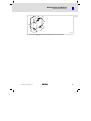
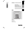
L−force Communication
Ä.>@Eä
EDBPM−H315
.>@E
Betriebsanleitung
Operating Instructions
Instructions de mise en service
HMI
F6
F1
F7
F2
F8
F3
VWX
YZ–
+/-
7
8
9
MNO
PQR
STU
4
5
6
DEF
GHI
JKL
1
2
3
shift
ABC
0
·
± space
F9
F4
F10
F5
PgUp
Info
Help
Clr
Esc
PgDN
Enter
EPM−H315
Bedieneinheit
Operating unit
Unité de commande
l
,
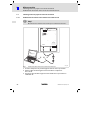
Lesen Sie zuerst diese Anleitung, bevor Sie mit den Arbeiten beginnen!
Beachten Sie die enthaltenen Sicherheitshinweise.
,
Please read these instructions before you start working!
Follow the enclosed safety instructions.
,
Veuillez lire attentivement cette documentation avant toute action !
Les consignes de sécurité doivent impérativement être respectées.
F6
F1
F7
F2
F8
F3
VWX
YZ–
+/-
7
8
9
MNO
PQR
STU
4
5
6
DEF
GHI
JKL
1
2
shift
F9
F4
F10
F5
PgUp
Info
Help
PgDN
3
ABC
·
± space
0
Clr
Esc
Enter
1
0
LCD adj.
INPUT VOLTAGE 18-32VDC 15W
FUSE 800mA
4 3 2 1
- +
VCANShield
CAN+
N.C.
N.C 24VDC
ASP8
3
1 2 3 4 5
2
h315_015
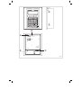
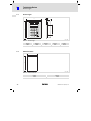
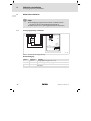
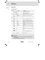
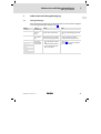
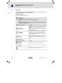
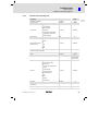
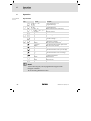
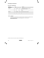
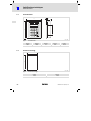
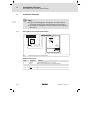
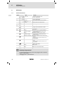
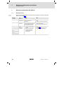
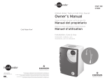
Legende zur Übersicht
Pos.
Beschreibung
Funktion
0
Klemmenleiste 4−polig
DC−Spannungsversorgung 24 V
1
Trimmer LCD ADJ
Display−Kontrast einstellen
2
Klemmenleiste 5−polig
Systembus (CAN)
3
Minidin−Buchse 8−polig
Serieller Port (ASP) für PC oder SPS
4
l
EDBPM−H315 DE/EN/FR 6.0
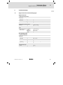
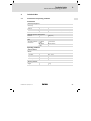
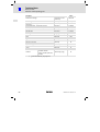
Diese Dokumentation ist gültig für ...
... die Bedieneinheit EPM−H315 ab der Typenschildbezeichnung:
Typ
EPM−H315
1A
10
Produktreihe
EPM
Bedieneinheit
Hardwarestand
Softwarestand
EDBPM−H315 DE/EN/FR 6.0
l
5
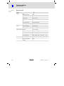
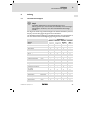
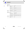
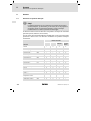
Dokumenthistorie
Was ist neu / was hat sich geändert?
Materialnummer
Version
Beschreibung
.>@E
6.0
04/2009
TD23
Neuauflage wegen Neuorganisation des Unternehmens
13238588
5.0
04/2007
TD 23
Fimierung gändert in Lenze Digitec Controls GmbH
00473989
4.0
05/2003
TD23
Überarbeitung, Fehlerbehebung
00457281
3.0
08/2002
TD23
Umfirmierung
00418422
2.0
08/2001
TD23
Komplette Überarbeitung zur Serie
00415798
1.0
06/2000
TD23
Erstauflage zum Feldtest
0Abb. 0Tab. 0
I
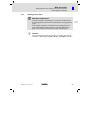
Tipp!
Dokumentationen und Software−Updates zu weiteren Lenze Produkten finden
Sie im Internet im Bereich "Services & Downloads" unter
http://www.Lenze.com
© 2009 Lenze Automation GmbH, Grünstraße 36, D−40667 Meerbusch
6
l
EDBPM−H315 DE/EN/FR 6.0
Inhalt
1
Vorwort und Allgemeines . . . . . . . . . . . . . . . . . . . . . . . . . . . . . . . . . . . . . . . . . .
1.1
1.2
1.3
1.4
2
4
5
9
9
9
10
Technische Daten . . . . . . . . . . . . . . . . . . . . . . . . . . . . . . . . . . . . . . . . . . . . . . . . .
11
2.1
2.2
Allgemeine Daten und Einsatzbedingungen . . . . . . . . . . . . . . . . . . .
Elektrische Daten . . . . . . . . . . . . . . . . . . . . . . . . . . . . . . . . . . . . . . . . . .
2.2.1
Eigenschaften der Bedieneinheit . . . . . . . . . . . . . . . . . . . .
2.2.2
Schnittstellenbeschreibung . . . . . . . . . . . . . . . . . . . . . . . . .
Abmessungen . . . . . . . . . . . . . . . . . . . . . . . . . . . . . . . . . . . . . . . . . . . . .
Einbauausschnitt . . . . . . . . . . . . . . . . . . . . . . . . . . . . . . . . . . . . . . . . . . .
11
12
13
15
16
16
Mechanische Installation . . . . . . . . . . . . . . . . . . . . . . . . . . . . . . . . . . . . . . . . . .
17
3.1
3.2
Bedieneinheit beschriften . . . . . . . . . . . . . . . . . . . . . . . . . . . . . . . . . . .
Bedieneinheit einbauen . . . . . . . . . . . . . . . . . . . . . . . . . . . . . . . . . . . . .
17
18
Elektrische Installation . . . . . . . . . . . . . . . . . . . . . . . . . . . . . . . . . . . . . . . . . . . .
20
4.1
4.2
Versorgungsspannung anschließen . . . . . . . . . . . . . . . . . . . . . . . . . . .
Systembus (CAN) verdrahten . . . . . . . . . . . . . . . . . . . . . . . . . . . . . . . . .
20
21
Inbetriebnahme . . . . . . . . . . . . . . . . . . . . . . . . . . . . . . . . . . . . . . . . . . . . . . . . . .
23
5.1
5.2
Erstes Einschalten . . . . . . . . . . . . . . . . . . . . . . . . . . . . . . . . . . . . . . . . . .
Projekt in die Bedieneinheit übertragen . . . . . . . . . . . . . . . . . . . . . . . .
5.2.1
Bedieneinheit und PC verbinden . . . . . . . . . . . . . . . . . . . . .
5.2.2
Projekt−Download . . . . . . . . . . . . . . . . . . . . . . . . . . . . . . . .
5.2.3
Verbindung zum PC entfernen . . . . . . . . . . . . . . . . . . . . . .
Statusmeldungen der Bedieneinheit . . . . . . . . . . . . . . . . . . . . . . . . . .
Kontrast einstellen . . . . . . . . . . . . . . . . . . . . . . . . . . . . . . . . . . . . . . . . .
23
24
24
25
26
27
27
Bedienung . . . . . . . . . . . . . . . . . . . . . . . . . . . . . . . . . . . . . . . . . . . . . . . . . . . . . .
28
6.1
6.2
6.3
6.4
28
29
31
32
5.3
5.4
6
7
9
Über diese Betriebsanleitung . . . . . . . . . . . . . . . . . . . . . . . . . . . . . . . . .
Verwendete Begriffe . . . . . . . . . . . . . . . . . . . . . . . . . . . . . . . . . . . . . . . .
Lieferumfang . . . . . . . . . . . . . . . . . . . . . . . . . . . . . . . . . . . . . . . . . . . . . .
Verwendete Hinweise . . . . . . . . . . . . . . . . . . . . . . . . . . . . . . . . . . . . . . .
2.3
2.4
3
i
Tastenfunktionen . . . . . . . . . . . . . . . . . . . . . . . . . . . . . . . . . . . . . . . . . .
Daten eingeben . . . . . . . . . . . . . . . . . . . . . . . . . . . . . . . . . . . . . . . . . . . .
Informationsmeldung aufrufen . . . . . . . . . . . . . . . . . . . . . . . . . . . . . .
Hilfemeldung aufrufen . . . . . . . . . . . . . . . . . . . . . . . . . . . . . . . . . . . . . .
Fehlersuche und Störungsbeseitigung . . . . . . . . . . . . . . . . . . . . . . . . . . . . . . .
33
7.1
33
Störungsmeldungen . . . . . . . . . . . . . . . . . . . . . . . . . . . . . . . . . . . . . . . .
EDBPM−H315 DE/EN/FR 6.0
l
7
i
8
9
8
Inhalt
Wartung . . . . . . . . . . . . . . . . . . . . . . . . . . . . . . . . . . . . . . . . . . . . . . . . . . . . . . . .
34
Anhang . . . . . . . . . . . . . . . . . . . . . . . . . . . . . . . . . . . . . . . . . . . . . . . . . . . . . . . . .
35
9.1
9.2
35
37
Chemikalienbeständigkeit . . . . . . . . . . . . . . . . . . . . . . . . . . . . . . . . . . .
Stichwortverzeichnis . . . . . . . . . . . . . . . . . . . . . . . . . . . . . . . . . . . . . . . .
l
EDBPM−H315 DE/EN/FR 6.0
Vorwort und Allgemeines
1
Über diese Betriebsanleitung
1
Vorwort und Allgemeines
Mit der Bedieneinheit können Sie auf Codestellen von Lenze Antriebsreglern,
Servo PLC 9300 und Drive PLC zugreifen und diese auf komfortable Weise steuern. Die Kommunikation erfolgt über Systembus (CAN).
Mit der Lenze−Software »HMI Designer« lässt sich die Programmierung der Bedieneinheit einfach realisieren.
1.1
Über diese Betriebsanleitung
ƒ Die vorliegende Betriebsanleitung dient dem sicheren und fehlerfreien
Arbeiten an und mit der Bedieneinheit.
ƒ Alle Personen, die an und mit der Bedieneinheit arbeiten, müssen bei ihren
Arbeiten die Betriebsanleitung verfügbar haben und die für sie relevanten
Angaben und Hinweise beachten.
ƒ Die Betriebsanleitung muss stets komplett und in einwandfrei lesbarem
Zustand sein.
1.2
1.3
Verwendete Begriffe
Begriff
Im folgenden Text verwendet für
Antriebsregler
Lenze Frequenzumrichter 8200 vector und 9300 vector,
Lenze Servo−Umrichter 9300 und 9400
HMI
Human Machine Interface
Lieferumfang
Lieferumfang
l
l
l
l
l
l
l
Wichtig
1 Bedieneinheit EPM−H315
1 Betriebsanleitung
4 Befestigungsschellen
4 Schrauben M4 x 35 mm
1 Dichtung
1 Klemmenleiste 4−polig, für den Anschluss
der DC−Spannungsversorgung
1 Klemmenleiste 5−polig, für den Anschluss
des Systembus (CAN)
EDBPM−H315 DE/EN/FR 6.0
l
Überprüfen Sie nach Erhalt der Lieferung sofort,
ob der Lieferumfang mit den Warenbegleitpapieren übereinstimmt. Für nachträglich reklamierte Mängel übernimmt Lenze keine Gewährleistung.
Reklamieren Sie
l erkennbare Transportschäden sofort beim
Anlieferer.
l erkennbare Mängel/Unvollständigkeit sofort bei der zuständigen Lenze−Vertretung.
9
1
Vorwort und Allgemeines
Verwendete Hinweise
1.4
Verwendete Hinweise
Um auf Gefahren und wichtige Informationen hinzuweisen, werden in dieser Dokumentation folgende Piktogramme und Signalwörter verwendet:
Sicherheitshinweise
Aufbau der Sicherheitshinweise:
}
Gefahr!
(kennzeichnet die Art und die Schwere der Gefahr)
Hinweistext
(beschreibt die Gefahr und gibt Hinweise, wie sie vermieden werden
kann)
Piktogramm und Signalwort
Bedeutung
{
Gefahr!
Gefahr von Personenschäden durch gefährliche elektrische Spannung
Hinweis auf eine unmittelbar drohende Gefahr, die den
Tod oder schwere Verletzungen zur Folge haben kann,
wenn nicht die entsprechenden Maßnahmen getroffen
werden.
}
Gefahr!
Gefahr von Personenschäden durch eine allgemeine
Gefahrenquelle
Hinweis auf eine unmittelbar drohende Gefahr, die den
Tod oder schwere Verletzungen zur Folge haben kann,
wenn nicht die entsprechenden Maßnahmen getroffen
werden.
(
Stop!
Gefahr von Sachschäden
Hinweis auf eine mögliche Gefahr, die Sachschäden zur
Folge haben kann, wenn nicht die entsprechenden
Maßnahmen getroffen werden.
Anwendungshinweise
Piktogramm und Signalwort
)
I
,
10
Bedeutung
Hinweis!
Wichtiger Hinweis für die störungsfreie Funktion
Tipp!
Nützlicher Tipp für die einfache Handhabung
Verweis auf andere Dokumentation
l
EDBPM−H315 DE/EN/FR 6.0
Technische Daten
2
Allgemeine Daten und Einsatzbedingungen
2
Technische Daten
2.1
Allgemeine Daten und Einsatzbedingungen
Allgemeine Daten
Konformität und Approbation
Konformität
CE
2004/108/EG
EMV−Richtlinie
cULus
Underwriter Laboratories Inc. (File−No. E189179)
Approbation
UL
Personenschutz und Geräteschutz
IP65 (frontseitig)
Schutzart
EMV
Angewandte Normen
zu Grenzwerten
EN 50081−2
(1994)
Störaussendung
EN 50082−2
(1995)
Störfestigkeit
Einsatzbedingungen
Umgebungsbedingungen
Klimatisch
Lagerung
−20 ... +60 °C
Transport
−20 ... +60 °C
Betrieb
0 ... +50 °C
Feuchtebeanspruchung
<85 %, keine Betauung
Montagebedingungen
0.7 kg
Gewicht
EDBPM−H315 DE/EN/FR 6.0
l
11
2
Technische Daten
Elektrische Daten
2.2
Elektrische Daten
Bereich
Display
Werte
Typ
LCD
Darstellungsformat
Text
Sichtbare Größe
70.4 × 20.8 mm
Zeilen × Zeichen
4 × 20
Zeichengröße
2.95 × 4.75 mm
Zeichengröße im Textmodus
5 × 7 Pixel
Fonts
ASCII, Katakana
Kontrasteinstellung
Trimmpotentiometer
Hintergrundbeleuchtung
LED
DC−Spannungsversorgung
+18 ... 32 VDC
Leistungsaufnahme
15 W bei 24 VDC
Absicherung
Feinsicherung Æ5 × 20 mm, 800 mA / F
Protokoll
Systembus (CAN)
Netzwerk−Topologie
Linie (beidseitig abgeschlossen mit 120 W)
Systembus−Teilnehmer
Master oder Slave
max. Anzahl Teilnehmer
63
Baudrate [kBit/s]
20
50
125
250
500
1000
max. Buslänge [m]
2500
1000
500
250
80
25
Speicher
Anwenderprogramm
256 kB
Schnittstellen
seriell
Elektrischer Anschluss
Netzwerk:
Systembus (CAN)
ASP8 (8−polige Minidin−
Buchse)
12
RS232
l
EDBPM−H315 DE/EN/FR 6.0
Technische Daten
2
Elektrische Daten
Eigenschaften der Bedieneinheit
2.2.1
Eigenschaften der Bedieneinheit
Beschreibung
Werte
Automatische Operationen
[Anzahl]
Backup/Wiederherstellen
[Funktion]
vorhanden
32
[Funktion]
vorhanden
Passwort ändern
Passwort Login
Passwort Logout
Befehle
Projekt beenden
Projektinformationen anzeigen
Sequenz−Verzeichnis anzeigen
Sprache ändern
Bit−Passwort
[Bit]
8
ABZIEHEN
EINGEBEN
Direktbefehl mit Wert− ODER
Struktur
UND
[Funktion]
vorhanden
XOR
ZUFÜGEN
Dynamische Texte (mit Bitgruppen−Struktur, Einzelbit−
Struktur oder Wert−Struktur)
[Anzahl]
Einer Sequenz zugeordnete LEDs
[Funktion]
Etiketten
[Funktion]
Frei definierbare Funktionstasten (F−Tasten)
[Anzahl]
1024 1)
vorhanden
vorhanden
5 (durch Doppelbelegung 10
Funktionen)
Bit permanent setzen
Bit permanent zurücksetzen
Bitumkehr
Direktbefehl mit Wert−Struktur
Echtzeitbit setzen
Funktion
Echtzeitbit zurücksetzen
[Funktion]
vorhanden
Interner Befehl
Keine
Makro
Sequenz
Taste deaktivieren
Gleichungen
[Anzahl]
Globale Eingabetasten (E−Tasten) mit fester Funktionsbelegung
[Funktion]
vorhanden
Globale Konfiguration Funktionstasten (F−Tasten)
[Funktion]
vorhanden
EDBPM−H315 DE/EN/FR 6.0
l
32
13
2
Technische Daten
Elektrische Daten
Eigenschaften der Bedieneinheit
Beschreibung
Werte
Informationsmeldungen
[insgesamt/gleichzeitig aktiv]
Interne Register
[Anzahl]
1024/128
2048 Byte
Lokale Eingabetasten (E−Tasten) mit fester Funktionsbe- [Funktion]
legung
vorhanden
Lokale Konfiguration Funktionstasten (F−Tasten)
[Funktion]
vorhanden
Makros (Total/Befehle ´ Makro)
[Anzahl]
Meldungens−Hilfen
[Anzahl]
Meldungsfeld
[Funktion]
Multilinguale Texte
[Anzahl Sprachen]
6
Passwort−Ebenen
[Anzahl]
10
Seiten
[Anzahl]
1024
Seiten−Hilfe
[Anzahl]
1024
[Anzahl]
64
Sequenz: beliebig
Sequenz: Start−/Stopp
1024/16
1024
Vorhanden
Systemmeldungen
[Funktion]
vorhanden
Textlisten
[Funktion]
vorhanden
Timer
[Anzahl]
32
[Anzahl je Seite]
30
Grenzwerte− und lineare Korrektur−Variablen
Variablen
1)
14
Numerische Variablen (DEC,
HEX, BIN, BCD)
von der Projektgröße begrenzter Richtwert
l
EDBPM−H315 DE/EN/FR 6.0
Technische Daten
2
Elektrische Daten
Schnittstellenbeschreibung
2.2.2
Schnittstellenbeschreibung
8
7
5
6
3
4
2
1
h310_010
Abb. 2−1
ASP8 Minidin 8pol. Buchse
Pin
Signal
1
Rx RS232 IN
2
Tx RS232 OUT
3
n. c.
4
RTS RS232 OUT
5
CTS RS232 IN
6
n. c.
7
Signal GND
8
+5 VCC (reserved)
n.c.
EDBPM−H315 DE/EN/FR 6.0
Nicht angeschlossen
l
15
2
Technische Daten
Abmessungen
2.3
Abmessungen
d
a
b
F6
F1
F7
F2
F8
F3
VWX
YZ–
+/-
7
8
9
MNO
PQR
STU
4
5
6
DEF
GHI
JKL
1
2
3
shift
·
ABC
0
± space
e
F9
F4
F10
F5
f
PgUp
Info
Help
Clr
Esc
PgDN
Enter
h315_001
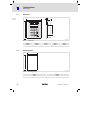
Abb. 2−2
2.4
Abmessungen
a [mm]
b [mm]
d [mm]
e [mm]
f [mm]
148.0
188.0
4.5
41.0
110.0
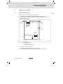
Einbauausschnitt
a
b
h315_002
Abb. 2−3
16
Einbauausschnitt
a [mm]
b [mm]
123.0
175.0
l
EDBPM−H315 DE/EN/FR 6.0
Mechanische Installation
3
Bedieneinheit beschriften
3
Mechanische Installation
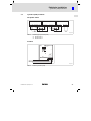
3.1
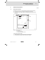
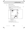
Bedieneinheit beschriften
Die Bedieneinheit kann mit auswechselbaren Schildern beschriftet werden.
ƒ Die Schilder sind nur bei ausgebauter Bedieneinheit zugänglich.
ƒ Beschriften Sie die Schilder, bevor Sie die Bedieneinheit in die Einbautafel
montieren.
LCD adj.
0
INPUT VOLTAGE: 18-32VDC 15W
FUSE 800mA
1
4 3 2 1
N.C. 24VDC
VCANShield
CAN+
N.C.
2
1 2 3 4 5
ASP8
h315_009
Abb. 3−1
Bedieneinheit beschriften
0
1
2
Firmenname
Maschinenbezeichnung
5 Funktionstasten (programmierbar)
So beschriften Sie die Schilder:
1. Schild 0, 1, oder 2 aus dem Schlitz ziehen und beschriften.
2. Anschließend beschriftetes Schild in den Schlitz schieben.
EDBPM−H315 DE/EN/FR 6.0
l
17
3
Mechanische Installation
Bedieneinheit einbauen
3.2
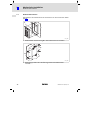
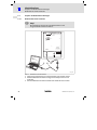
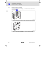
Bedieneinheit einbauen
Die Maße für den Einbauausschnitt entnehmen Sie den technischen Daten.
(¶ 16)
0
1
h315_006
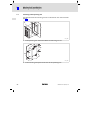
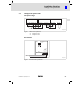
1. Bedieneinheit 0 mit Dichtung 1 in den Einbauausschnitt schieben.
2
2
h315_010
2. Befestigungsschellen 2 in die Öffnungsschlitze der Bedieneinheit
schieben.
18
l
EDBPM−H315 DE/EN/FR 6.0
Mechanische Installation
3
Bedieneinheit einbauen
3
3
h315_011
3. Schrauben 3 gegen die Einbautafel drehen und festziehen.
EDBPM−H315 DE/EN/FR 6.0
l
19
4
Elektrische Installation
Versorgungsspannung anschließen
4
Elektrische Installation
(
Stop!
ƒ Beschädigung angeschlossener Geräte. Verbinden Sie den
PE−Leiter so wie es in der Abbildung dargestellt ist!
ƒ Bedieneinheit nur im spannungslosen Zustand verdrahten!
4.1
Versorgungsspannung anschließen
L1
N
PE
LCD adj.
INPUT VOLTAGE: 18-32VDC 15W
FUSE 800mA
4 3 2 1
~
N.C.
24VDC
–
VCANShield
CAN+
N.C.
+18...32VDC
ASP8
12 3 4 5
h315_003
Abb. 4−1
Anschluss der Versorgungsspannung
Klemmenbelegung
Klemme
Bezeichnung
Erläuterung
1
DC +24 V
Versorgungsspannung (DC +18 V ... 32 V)
2
DC 0 V
GND Versorgungsspannung, Bezugspotential
3
n. c.
Nicht angeschlossen
4
20
PE−Potential
l
EDBPM−H315 DE/EN/FR 6.0
Elektrische Installation
4
Systembus (CAN) verdrahten
4.2
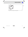
Systembus (CAN) verdrahten
Prinzipieller Aufbau
A2
A 1 (H315)
-V
CG LO HI
CAN- Shield CAN+ N.C.
An
CG LO HI
CG LO HI
CG LO HI
120
120
h315_004
Abb. 4−2
Verdrahtung des Systembus (CAN)
A1
A2
An
Busteilnehmer 1
Busteilnehmer 2
Busteilnehmer n
Anschluss
LCD adj.
INPUT VOLTAGE: 18-32VDC 15W
FUSE 800mA
VCANShield
CAN+
N.C.
N.C.
24VDC
4 3 2 1
ASP8
12 3 4 5
CAN-GND
CAN-LOW
CAN-HIGH
h315_017
Abb. 4−3
EDBPM−H315 DE/EN/FR 6.0
Anschluss Systembus (CAN)
l
21
4
Elektrische Installation
Systembus (CAN) verdrahten
Klemmenbelegung
(
Stop!
Schließen Sie einen 120 W Abschlusswiderstand am ersten und
letzten Bus−Teilnehmer an.
Klemme
Bezeichnung
Erläuterung
1
V−
GND
Bezugspotential
2
CAN−
LO
Systembus LOW (Datenleitung)
3
Shield
4
CAN+
5
n. c.
Schirm des Systembus−Kabels auflegen
HI
Systembus HIGH (Datenleitung)
Nicht angeschlossen
Folgen Sie bei der Verwendung des Übertragungskabels unseren Empfehlungen:
Spezifikation des Übertragungskabels
22
Gesamtlänge
£ 300 m
£ 1000 m
Kabeltyp
LIYCY 2 x 2 x 0,5 mm2
(paarverseilt mit Abschirmung)
CYPIMF 2 x 2 x 0,5 mm2
(paarverseilt mit Abschirmung)
Leitungswiderstand
£ 80 W/km
£ 80 W/km
Kapazitätsbelag
£ 130 nF/km
£ 60 nF/km
l
EDBPM−H315 DE/EN/FR 6.0
Inbetriebnahme
5
Erstes Einschalten
5
Inbetriebnahme
5.1
Erstes Einschalten
Für die Inbetriebnahme ist eine vollständige Verdrahtung des Systembus notwendig.
Überprüfen Sie vor dem Einschalten der Versorgungsspannung ...
ƒ die gesamte Verdrahtung auf Vollständigkeit und Kurzschluss,
ƒ ob das Bussystem beim physikalisch ersten und letzten Busteilnehmer
abgeschlossen ist.
EDBPM−H315 DE/EN/FR 6.0
l
23
5
Inbetriebnahme
Projekt in die Bedieneinheit übertragen
Bedieneinheit und PC verbinden
5.2
Projekt in die Bedieneinheit übertragen
5.2.1
Bedieneinheit und PC verbinden
(
Stop!
Die Verbindung zwischen PC und Bedieneinheit nur bei
ausgeschalteten Geräten herstellen!
LCD adj.
INPUT VOLTAGE: 18-32VDC 15W
FUSE 800mA
4 3 2 1
VCANShield
CAN+
N.C.
N.C. 24VDC
ASP8
1 2 3 4 5
l
HMI D
esigne
r
2
1
0
h315_005
Abb. 5−1
Bedieneinheit und PC verbinden
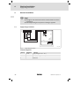
1. Programmieradapter EPZ−H111 0 auf die ASP8−Schnittstelle stecken.
2. Downloadkabel EPZ−H110 1 mit Programmieradapter EPZ−H111 0
verbinden.
3. Downloadkabel EPZ−H110 1 auf COM1 oder COMx 2 am PC stecken.
24
l
EDBPM−H315 DE/EN/FR 6.0
Inbetriebnahme
5
Projekt in die Bedieneinheit übertragen
Projekt−Download
5.2.2
Projekt−Download
)
Hinweis!
Im »HMI Designer« können Sie auswählen, ob mit dem Laden des
Projekts gleichzeitig die Firmware aktualisiert werden soll.
Die Firmware muss immer beim ersten Download eines Projekts in
die Bedieneinheit bzw. nach einem Update des Projektierungstool
»HMI Designer« aktualisiert werden.
I
Tipp!
Beispiel−Projekte für die Bedieneinheit finden Sie im
Projektierungstool »HMI Designer« unter Datei W Öffnen...
W Samples.
EDBPM−H315 DE/EN/FR 6.0
l
25
5
Inbetriebnahme
Projekt in die Bedieneinheit übertragen
Verbindung zum PC entfernen
Boot forced
ENTER to download
System autotest OK
F6
F1
VWX
F7
F2
YZ–
F8
F3
+/-
7
8
9
MNO
PQR
STU
4
5
6
DEF
GHI
JKL
1
shift
2
ABC
0
F9
F4
F10
F5
PgUp
Info
Help
PgDN
3
·
± space
Clr
Esc
Enter
0
h315_007
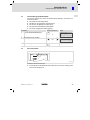
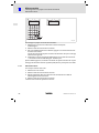
So übertragen Sie ein Projekt in die Bedieneinheit:
1. PC einschalten und Projektierungstool HMI Designer starten.
2. Versorgungsspannung für Bedieneinheit einschalten.
3. Wenn auf dem Display die Meldung ENTER to download" erscheint, die
Enter−Taste 0 an der Bedieneinheit drücken.
Die Bedieneinheit ist für den Datenempfang bereit, wenn auf dem Display
die Meldung Boot forced" erscheint.
4. Gewünschtes Projekt vom HMI Designer in die Bedieneinheit laden.
– Siehe Handbuch "HMI Designer − Erste Schritte".
Nach dem Download ist die Bedieneinheit betriebsbereit und kann über den Systembus (CAN) mit den angeschlossenen Teilnehmern Daten austauschen.
5.2.3
Verbindung zum PC entfernen
So entfernen Sie die Verbindung zum PC:
1. PC ausschalten.
2. Versorgungsspannung für Bedieneinheit abschalten.
3. Programmieradapter EPZ−H111 an der Bedieneinheit und Downloadkabel
EPZ−H110 am PC abziehen.
4. Versorgungsspannung für Bedieneinheit einschalten.
Die Bedieneinheit ist betriebsbereit.
26
l
EDBPM−H315 DE/EN/FR 6.0
Inbetriebnahme
5
Statusmeldungen der Bedieneinheit
5.3
Statusmeldungen der Bedieneinheit
Sie können jederzeit den Status der Bedieneinheit abfragen. Sie erhalten Informationen über:
ƒ Die serielle Schnittstelle (Serial)
ƒ Den Namen des geladenen Treibers (Driver)
ƒ Die Version des geladenen Treibers (Ver.)
ƒ Die Netzadresse der Bedieneinheit (Addr.)
ƒ Die zuletzt aufgetretene Störung (Error)
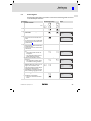
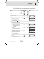
Sie möchten ...
A
Drücken Sie die Tasten ...
den Status der Bedieneinheit abfragen.
Serial: NET
Driver: Can Lenze S
Ver. : 1.03
Up/ Down : next page
shift
2x
B
die nächste Statusseite anwählen.
PgUp
PgDN
oder
Beispiel
Addr. : FROM PRJ:010
Error : NO ERROR
Up/ Down : next page
C
5.4
die Statusanzeige schließen.
Clr
Esc
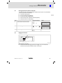
Kontrast einstellen
0
LCD adj.
INPUT VOLTAGE: 18-32VDC 15W
FUSE 800mA
4 3 2 1
N.C. 24VDC
h315_012
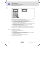
So stellen Sie den Kontrast ein:
ƒ Auf der Rückseite der Bedieneinheit stellen Sie mit Trimmer LCD adj. 0 den
Kontrast des Displays ein.
EDBPM−H315 DE/EN/FR 6.0
l
27
6
Bedienung
Tastenfunktionen
6
Bedienung
6.1
Tastenfunktionen
Tasten
Funktion
Beschreibung
<F1> ... <F5>
Funktion von F1 ... F5 ausführen
(Tasten programmierbar)
<F6> ... <F10>
Funktion von F6 ... F10 ausführen
(Tasten programmierbar)
<0> ... <9>
<ABC> ... <YZ—>, <+/−>
Alphanumerische Tasten für die Dateneingabe
·
<± space>
Vorzeichen bzw. Leerzeichen eingeben
·
<·>
Gleitkomma eingeben
<Esc>
Parametereingabe abbrechen; Hilfe−, Informations−und Statusmeldungen verlassen
<Clr>
Parameter−Ebene: Stellt während der Dateneingabe den ursprünglichen Wert wieder her
PgUp
<PgUp>
<Pfeil auf>
Menü−Ebene: Zur vorherigen Seite wechseln
Parameter−Ebene: Vorherigen dynamischen Text
anwählen
PgDN
<PgDn>
<Pfeil ab>
Menü−Ebene: Zur nächsten Seite wechseln
Parameter−Ebene: Nächsten dynamischen Text
anwählen
<Pfeil links>
Menü−Ebene: Cursor auf das vorherige Feld stellen
Parameter−Ebene: Cursor auf die vorherige Ziffer
stellen
<Pfeil rechts>
Menü−Ebene: Cursor auf das nächste Feld stellen
Parameter−Ebene: Cursor auf die nächste Ziffer
stellen
<Enter>
Parameter zum Eingeben eines Wertes anwählen
Übernehmen des eingegebenen Wertes
<Help>
Hilfe−Text aufrufen
<Info>
Info−Text aufrufen
F6
F1
shift
+
F6
F1
ABC
0
...
...
...
F10
F5
F10
F5
+/-
9
±space
shift
+
±space
Clr
Esc
shift
+
Clr
Esc
Enter
Help
Info
)
Hinweis!
Die Funktionstasten (Fx) sind über die Software »HMI Designer«
programmierbar.
ƒ Lenze−Einstellung: Ohne Funktion.
28
l
EDBPM−H315 DE/EN/FR 6.0
Bedienung
6
Daten eingeben
6.2
Daten eingeben
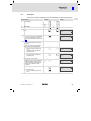
Das Eingeben oder Ändern von Daten ist Schritt für Schritt dargestellt und wird
an einem Beispiel erläutert.
Sie möchten ...
A
Drücken Sie die Tasten ...
ein Menü auswählen.
F6
F1
bzw.
B
eine Seite anwählen.
C
den Cursor auf das vorherige oder nächste Feld stellen.
D
in die Parameter−Ebene wechseln.
l Der Cursor stellt sich auf die rechte
Ziffer.
l In einem dynamischen Textfeld stellt
sich der Cursor auf das linke Zeichen
(siehe Schritt I).
E
shift
+
F6
F1
PgUp
...
...
oder
Beispiel
F10
F5
F10
F5
PgDN
oder
Enter
Feld 1
Feld 2
Feld 3
ON
-9876
1A3F
Feld 1
Feld 2
Feld 3
ON
-9876
1A3F
Feld 1
Feld 2
Feld 3
ON
0001
1A3F
Feld 1
Feld 2
Feld 3
ON
0012
1A3F
Feld 1
Feld 2
Feld 3
ON
012.
1A3F
Feld 1
Feld 2
Feld 3
ON
-12.34
1A3F
einen Wert vollständig neu eingeben.
1. Wechseln Sie in die Parameter−Ebene
(siehe Schritt D).
2. Lassen Sie den Cursor auf der rechten
Ziffer stehen
3. Geben Sie den Wert der ersten Stelle
ein.
– Alle anderen Stellen werden auf
Null gesetzt.
– Die eingegebene Ziffer wird eine
Stelle nach links geschoben.
ABC
0
4. Geben Sie den Wert der nächsten
Stelle ein.
– Die eingegebenen Ziffern werden
eine Stelle nach links geschoben.
ABC
0
5. Geben Sie ggf. ein Komma ein.
TIPP! Sie können ein Komma nur einfügen, wenn das Feld als Floating Point" definiert ist (siehe Projektierungstool HMI Designer").
6. Wiederholen Sie Schritt 4. bis Sie den
Wert vollständig eingegeben haben.
shift
+
·
±space
·
7. Geben Sie ggf. ein Vorzeichen ein.
±space
8. Bestätigen Sie die Eingabe.
– Der Cursor wechselt in die Menü−
Ebene.
EDBPM−H315 DE/EN/FR 6.0
...
+/-
...
ABC
9
0
Enter
l
29
6
Bedienung
Daten eingeben
Sie möchten ...
F
Drücken Sie die Tasten ...
2. Wählen Sie die gewünschte Ziffer.
G
oder
3. Ändern Sie die Ziffer.
ABC
4. Bestätigen Sie die Eingabe.
– Der Cursor wechselt in die Menü−
Ebene.
Enter
0
4. Geben Sie den Wert der nächsten
Stelle ein (z. B. D").
– Die eingegebenen Ziffern werden
eine Stelle nach links geschoben.
5. Wiederholen Sie Schritt 4. bis Sie den
Wert vollständig eingegeben haben.
6. Bestätigen Sie die Eingabe.
– Der Cursor wechselt in die Menü−
Ebene.
ABC
0
ABC
0
3x
2x
+/-
Feld 1
Feld 2
Feld 3
ON
-1934
1A3F
Feld 1
Feld 2
Feld 3
ON
-1934
1A3F
Feld 1
Feld 2
Feld 3
ON
-1934
000B
Feld 1
Feld 2
Feld 3
ON
-1934
00BD
Feld 1
Feld 2
Feld 3
ON
-1934
1C3F
9
Enter
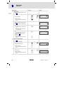
eine hexadezimale Ziffer ändern.
1. Wechseln Sie in die Parameter−Ebene
(siehe Schritt D).
2. Wählen Sie die gewünschte Ziffer.
3. Ändern Sie die Ziffer (z. B. C").
4. Bestätigen Sie die Eingabe.
– Der Cursor wechselt in die Menü−
Ebene.
30
...
einen hexadezimalen Wert vollständig
neu eingeben.
1. Wechseln Sie in die Parameter−Ebene
(siehe Schritt D).
2. Lassen Sie den Cursor auf der rechten
Ziffer stehen.
3. Geben Sie den Wert der ersten Stelle
ein (z. B. B").
– Alle anderen Stellen werden auf
Null gesetzt.
– Die eingegebene Ziffer wird eine
Stelle nach links geschoben.
H
Beispiel
eine einzelne Ziffer ändern.
1. Wechseln Sie in die Parameter−Ebene
(siehe Schritt D).
oder
ABC
0
4x
Enter
l
EDBPM−H315 DE/EN/FR 6.0
Bedienung
6
Informationsmeldung aufrufen
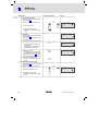
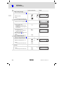
Sie möchten ...
I
Drücken Sie die Tasten ...
1. Wählen Sie den Text aus.
Help
á
2. Bestätigen Sie die Eingabe.
– Der Cursor wechselt in die Menü−
Ebene.
6.3
Beispiel
ein dynamisches Textfeld ändern.
oder
Info
â
Feld 1
Feld 2
Feld 3
ON
-9876
1A3F
Enter
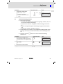
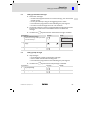
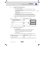
Informationsmeldung aufrufen
ƒ Informationsmeldungen
– sind Texte, die aufgrund eines Ereignisses angezeigt werden (z. B., wenn
ein Istwert eine Grenze übersteigt),
– können Sie nur aufrufen, solange das auslösende Ereignis vorhanden
ist,
– müssen im Projektierungstool HMI Designer" programmiert worden
sein,
– können max. 2 Zeilen × 20 Zeichen lang sein.
ƒ Die zweitletzte Zeile enthält ein programmierbares Meldungsfeld. Dieses
Feld zeigt die numerische Größe der Variablen, die die Meldung aktiviert
hat.
ƒ Die LED in der Taste
Info
blinkt, wenn eine Informationsmeldung
vorhanden ist.
Sie möchten ...
A
Drücken Sie die Tasten ...
eine Informationsmeldung aufrufen.
l Eine Informationsmeldung, die Sie zum erstenmal aufrufen, ist mit ** gekennzeichnet.
B
die vorherige oder nächste Informationsmeldung anwählen.
C
die Informationsmeldung schließen.
EDBPM−H315 DE/EN/FR 6.0
Druck uebersteigt
die Sicherheitsgrenze
125.5
Info
PgUp
Beispiel
oder
PgDN
**
Wasserstand unterhalb
der Arbeitsschwelle
40
Clr
Esc
l
31
6
Bedienung
Hilfemeldung aufrufen
6.4
Hilfemeldung aufrufen
ƒ Hilfemeldungen
– können Seiten oder Informationsmeldungen zugeordnet sein.
– enthalten nützliche Hinweise, die die Bedienung erleichtern.
– müssen im Projektierungstool HMI Designer" programmiert worden
sein.
ƒ Die LED in der Taste
Sie möchten ...
A
eine Hilfemeldung aufrufen.
B
die Hilfemeldung schließen.
32
Help
blinkt, wenn eine Hilfemeldung vorhanden ist.
Drücken Sie die Tasten ...
Beispiel
Help
Clr
Esc
l
EDBPM−H315 DE/EN/FR 6.0
Fehlersuche und Störungsbeseitigung
7
Störungsmeldungen
7
Fehlersuche und Störungsbeseitigung
7.1
Störungsmeldungen
Rufen Sie die Statusmeldungen der Bedieneinheit auf, um die zuletzt aufgetretene Störungsmeldung anzuzeigen. (¶ 27)
Display
Störung
Ursache
Abhilfe
NO ERROR
Keine Störung
−
−
PR ERROR
Fehlerhafter
Datenaustausch
Verbindung zwischen Bedieneinheit und PC ist fehlerhaft
l
COM BROK
Kommunikation unterbrochen
Serielles Datenkabel zwischen
Bedieneinheit und PC ist defekt
oder nicht richtig angeschlossen
l
ASIC ko1
Kommunikation mit Systembus (CAN)
unterbrochen
l
Fehlerhafte Verdrahtung
(z. B. Verpolung) des Systembus
Fehlerhafte Parametrierung
der Schnittstelle (Baudrate,
Adresse, Identifier)
l
ASIC ko2
ASIC ko3
ASIC ko4
RESET
l
l
l
l
Anschlüsse auf festen Sitz prüfen
Leitung auf Beschädigung kontrollieren
Sub−D−Stecker auf richtigen Anschluss und festen Sitz prüfen
Serielles Datenkabel austauschen
Verdrahtung Systembus (CAN) prüfen (^ 21)
Parametrierung prüfen (^ HMI Designer − Erste Schritte).
SDOERR 6
SDOERR 5
SDOERR 3
EDBPM−H315 DE/EN/FR 6.0
l
33
8
Wartung
8
Wartung
Die Bedieneinheit ist wartungsfrei, wenn die vorgeschriebenen Einsatzbedingungen eingehalten werden. (¶ 11)
ƒ Reinigen Sie die Bedieneinheit mit denaturiertem Äthylalkohol.
ƒ Wenn Sie ein anderes Reinigungsmittel verwenden müssen, um
Verunreinigungen zu beseitigen, beachten Sie die Angaben in der Tabelle
im Kap. 9.1. (¶ 35)
34
l
EDBPM−H315 DE/EN/FR 6.0
Anhang
9
Chemikalienbeständigkeit
9
Anhang
9.1
Chemikalienbeständigkeit
(
Stop!
Die Bedien−Oberfläche ist wenig beständig gegen saure
Nahrungsmittel (z. B. Tomatensaft, Zitronensaft). Verschmutzungen
deshalb gleich entfernen, sonst kann die Oberfläche beschädigt
werden.
Die folgende Tabelle zeigt die Beständigkeit der Bedien−Oberfläche (Tastatur,
Display, Touch Screen) gegen die genannten Chemikalien.
Für die Bedieneinheiten EPM−H5xx und EPM−H6xx bietet Lenze Schutzfolien an,
mit einer verbesserten Beständigkeit gegen die genannten Chemikalien.
Bedieneinheit
EPM−H3xx
EPM−H4xx
EPM−H5xx
EPM−H6xx
mit Schutzfolie
Substanz
L
L
J
Ameisensäure
³ 50 %
L
L
Ammoniak
³2%
L
L
L
L
L
Aceton
Äthylenglykol
Ätznatron
³2%
L
L
Beizlösung
konzentriert
L
Benzin
J
L
L
J
Benzol
J
J
L
J
Benzylalkohol
L
L
L
L
Dieselöl
J
J
J
J
Eisessig
L
L
L
L
L
J
Ethanol
L
L
L
J
Hochdruck und Temperatur > 100 °C
L
L
Isopropanol
J
J
L
J
Methanol
J
J
L
L
Chlorwasserstoffsäure
Essigsäure
³ 10 %
³ 5 % < 50 %
L
Mineralsäuren
konzentriert
L
L
Natriumhydroxid
³ 50 %
L
L
L
L
J
L
L
L
L
Methylenchlorid
Perchlorethylen
Phosphorsäure
EDBPM−H315 DE/EN/FR 6.0
³ 30 %
l
35
9
Anhang
Chemikalienbeständigkeit
Bedieneinheit
EPM−H3xx
EPM−H4xx
EPM−H5xx
EPM−H6xx
mit Schutzfolie
Substanz
Salpetersäure
³ 5 % < 10 %
L
L
L
J
Schwefelsäure
³ 50 %
L
L
L
L
Toluol
J
J
L
J
Trichlorethylen
L
J
Unterchlorigsaures Natron
³ 20 %
L
L
Wasserstoffsuperoxyd
³ 25 %
L
L
EPM−H3xx
EPM−H4xx
EPM−H5xx
EPM−H6xx
J
L
36
EPM−H310, EPM−H312, EPM−H315
EPM−H410
EPM−H502, EPM−H505, EPM−H507, EPM−H510, EPM−H515, EPM−H520,
EPM−H521, EPM−H525
EPM−H605, EPM−H606
Oberfläche ist beständig, keine sichtbare Beschädigung
Oberfläche ist nicht beständig, wird beschädigt
nicht getestet
l
EDBPM−H315 DE/EN/FR 6.0
Anhang
9
Stichwortverzeichnis
9.2
Stichwortverzeichnis
A
Einbauausschnitt, 16
Allgemeine Daten, 11
Einsatzbedingungen, 11
− Feuchtebeanspruchung, 11
− Montagebedingungen, Gewicht, 11
− Umgebungsbedingungen, klimatisch, 11
Anschluß, elektischer, 12
Antriebsregler, 9
B
Einschalten, erstes, 23
Baudrate, Systembus (CAN), 12
Elektrische Daten, 12
Bedieneinheit
Elektrische Installation, 20
−
−
−
−
−
−
−
−
−
−
− Versorgungsspannung anschließen, 20
Daten eingeben, 29
Eigenschaften, 13
Funktion der Tasten, 28
Hilfemeldung aufrufen, 32
Informationsmeldung aufrufen, 31
Projekt in die übertragen, 24
Schnittstellenbeschreibung, 15
Statusmeldungen, 27
Verbindung zum PC entfernen, 26
Verbindung zum PC herstellen, 24
Erstes Einschalten, 23
F
Fehlersuche, 33
− Störungsmeldungen, 33
Feuchtebeanspruchung, 11
H
Hilfemeldung, 32
Bedienung, 28
Hinweise, Definiton, 10
Begriffsdefinitionen, 9
Human Machine Interface, 9
C
I
Chemikalienbeständigkeit, 35
Inbetriebnahme, 23
D
− Erstes Einschalten, 23
Daten, eingeben, 29
Informationsmeldungen, 31
DC−Spannungsversorgung, 12
Installation, Systembus (CAN), 21
Definition der verwendeten Hinweise, 10
Installation, elektrische, 20
Display, 12
Installation, elektrische , Versorgungsspannung
anschließen, 20
− Kontrast einstellen, 27
Installation, mechanische, 17
E
Eigenschaften, 13
EDBPM−H315 DE/EN/FR 6.0
l
37
9
Anhang
Stichwortverzeichnis
K
Störungsbeseitigung, 33
Kabeltyp, 22
Störungsmeldungen, 33
Kapazitätsbelag, 22
Systembus (CAN)
Kontrast, einstellen, 27
− Baudrate, 12
− Verdrahtung, 21
L
Leistungsaufnahme, 12
Leitungswiderstand, 22
M
Mechanische Installation, 17
Montagebedingungen, Gewicht, 11
P
PC
− Verbindung zur Bedieneinheit entfernen, 26
− Verbindung zur Bedieneinheit herstellen, 24
Projekt, in die Bedieneinheit übertragen, 24
Projekt−Download, 25
S
Sicherheitshinweise
− Definition, 10
− Gestaltung, 10
Speicher, 12
T
Tastenfunktionen, 28
Technische Daten, 11
−
−
−
−
−
−
−
−
−
DC−Spannungsversorgung, 12
Display, 12
Einbauausschnitt, 16
Elektrische Daten, 12
elektrischer Anschluß, 12
Leistungsaufnahme, 12
Schnittstellenbeschreibung, 15
Speicher, 12
Systembus (CAN), 12
U
Umgebungsbedingungen, klimatisch, 11
V
Versorgungsspannung anschließen, 20
W
Wartung, 34
Statusmeldungen, 27
38
l
EDBPM−H315 DE/EN/FR 6.0
Anhang
9
Stichwortverzeichnis
EDBPM−H315 DE/EN/FR 6.0
l
39
Key for the overview
Pos.
Description
Function
0
Terminal strip, 4−pole
DC−voltage supply 24 V
1
Trimmer LCD ADJ
Setting display contrast
2
Terminal strip, 5−pole
System bus (CAN)
3
Minidin socket, 8−pole
ASP serial port for PC or PLC
40
l
EDBPM−H315 DE/EN/FR 6.0
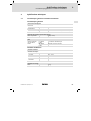
This documentation applies to ...
... EPM−H315 operating units as of the following nameplate data:
Type
EPM−H315
1A
10
Product range
EPM
operating unit
Hardware version
Software version
EDBPM−H315 DE/EN/FR 6.0
l
41
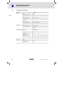
Document history
What is new / what has changed?
Material number
Version
Description
.>@E
6.0
04/2009
TD23
New edition due to reorganisation of the company
13238588
5.0
02/2008
TD23
Change of company name to Lenze Digitec Controls
GmbH
00473989
4.0
05/2003
TD23
Revision, error correction
00457281
3.0
08/2002
TD23
Change of company name
00418422
2.0
08/2001
TD23
Complete revision of series
00415798
1.0
06/2000
TD23
First edition for field test
0Fig. 0Tab. 0
I
Tip!
Documentation and software updates for further Lenze products can be found
on the Internet in the "Services & Downloads" area under
http://www.Lenze.com
© 2009 Lenze Automation GmbH, Grünstraße 36, D−40667 Meerbusch
42
l
EDBPM−H315 DE/EN/FR 6.0
Contents
1
2
Preface and general information . . . . . . . . . . . . . . . . . . . . . . . . . . . . . . . . . . .
45
1.1
1.2
1.3
1.4
About these Operating Instructions . . . . . . . . . . . . . . . . . . . . . . . . . . .
Terminology used . . . . . . . . . . . . . . . . . . . . . . . . . . . . . . . . . . . . . . . . . .
Scope of supply . . . . . . . . . . . . . . . . . . . . . . . . . . . . . . . . . . . . . . . . . . . .
Notes used . . . . . . . . . . . . . . . . . . . . . . . . . . . . . . . . . . . . . . . . . . . . . . . .
45
45
45
46
Technical data . . . . . . . . . . . . . . . . . . . . . . . . . . . . . . . . . . . . . . . . . . . . . . . . . . .
47
2.1
2.2
General data and operating conditions . . . . . . . . . . . . . . . . . . . . . . .
Electrical data . . . . . . . . . . . . . . . . . . . . . . . . . . . . . . . . . . . . . . . . . . . . .
2.2.1
Features of the operating unit . . . . . . . . . . . . . . . . . . . . . .
2.2.2
Interface description . . . . . . . . . . . . . . . . . . . . . . . . . . . . . .
Dimensions . . . . . . . . . . . . . . . . . . . . . . . . . . . . . . . . . . . . . . . . . . . . . . .
Mounting cutout . . . . . . . . . . . . . . . . . . . . . . . . . . . . . . . . . . . . . . . . . . .
47
48
49
51
52
52
Mechanical installation . . . . . . . . . . . . . . . . . . . . . . . . . . . . . . . . . . . . . . . . . . . .
53
3.1
3.2
Labelling of operating unit . . . . . . . . . . . . . . . . . . . . . . . . . . . . . . . . . . .
Mounting of the operating unit . . . . . . . . . . . . . . . . . . . . . . . . . . . . . .
53
54
Electrical installation . . . . . . . . . . . . . . . . . . . . . . . . . . . . . . . . . . . . . . . . . . . . . .
56
4.1
4.2
Supply voltage connection . . . . . . . . . . . . . . . . . . . . . . . . . . . . . . . . . . .
Wiring of the system bus (CAN) . . . . . . . . . . . . . . . . . . . . . . . . . . . . . . .
56
57
Commissioning . . . . . . . . . . . . . . . . . . . . . . . . . . . . . . . . . . . . . . . . . . . . . . . . . .
59
5.1
5.2
Initial switch−on . . . . . . . . . . . . . . . . . . . . . . . . . . . . . . . . . . . . . . . . . . . .
Project transfer to the operating unit . . . . . . . . . . . . . . . . . . . . . . . . . .
5.2.1
Connecting operating unit and PC . . . . . . . . . . . . . . . . . . .
5.2.2
Project download . . . . . . . . . . . . . . . . . . . . . . . . . . . . . . . . .
5.2.3
Disconnecting from the PC . . . . . . . . . . . . . . . . . . . . . . . . .
Status messages of the operating unit . . . . . . . . . . . . . . . . . . . . . . . . .
Contrast setting . . . . . . . . . . . . . . . . . . . . . . . . . . . . . . . . . . . . . . . . . . . .
59
60
60
61
62
63
63
Operation . . . . . . . . . . . . . . . . . . . . . . . . . . . . . . . . . . . . . . . . . . . . . . . . . . . . . . .
64
6.1
6.2
6.3
6.4
64
65
67
67
2.3
2.4
3
4
5
5.3
5.4
6
7
i
Key functions . . . . . . . . . . . . . . . . . . . . . . . . . . . . . . . . . . . . . . . . . . . . .
Data input . . . . . . . . . . . . . . . . . . . . . . . . . . . . . . . . . . . . . . . . . . . . . . . .
Calling up information messages . . . . . . . . . . . . . . . . . . . . . . . . . . . . .
Calling up help messages . . . . . . . . . . . . . . . . . . . . . . . . . . . . . . . . . . . .
Troubleshooting and fault elimination . . . . . . . . . . . . . . . . . . . . . . . . . . . . . .
68
7.1
68
Fault messages . . . . . . . . . . . . . . . . . . . . . . . . . . . . . . . . . . . . . . . . . . . .
EDBPM−H315 DE/EN/FR 6.0
l
43
i
Contents
8
Maintenance . . . . . . . . . . . . . . . . . . . . . . . . . . . . . . . . . . . . . . . . . . . . . . . . . . . .
9
Appendix . . . . . . . . . . . . . . . . . . . . . . . . . . . . . . . . . . . . . . . . . . . . . . . . . . . . . . .
70
9.1
9.2
70
72
44
Chemical resistance . . . . . . . . . . . . . . . . . . . . . . . . . . . . . . . . . . . . . . . .
Index . . . . . . . . . . . . . . . . . . . . . . . . . . . . . . . . . . . . . . . . . . . . . . . . . . . . .
l
69
EDBPM−H315 DE/EN/FR 6.0
Preface and general information
1
About these Operating Instructions
1
Preface and general information
The operating unit enables you to access codes of Lenze controllers, 9300
Servo PLCs and Drive PLCs and to control them in a comfortable way.
Communication takes place via the system bus (CAN).
The Lenze »HMI Designer« software makes programming of the operating unit
easy.
1.1
About these Operating Instructions
ƒ These Operating Instructions serve to ensure safe and trouble−free
working on and with the operating unit.
ƒ All persons working on and with the operating unit must have these
Operating Instructions available and observe the information and notes
relevant for them.
ƒ These Operating Instructions must always be complete and perfectly
readable.
1.2
1.3
Terminology used
Term
Used in this text for
Controller
Lenze 8200 vector and 9300 vector frequency inverter, Lenze 9300
and 9400 servo inverter
HMI
Human Machine Interface
Scope of supply
Scope of supply
l
l
l
l
l
l
l
Important
1 EPM−H315 operating unit
1 Operating Instructions
4 mounting clamps
4 screws M4 x 35 mm
1 seal
1 terminal strip, 4−pole for connection of DC
voltage supply
1 terminal strip, 5−pole for system bus (CAN)
connection
EDBPM−H315 DE/EN/FR 6.0
l
After receipt of the delivery, check immediately
whether the items delivered match the
accompanying papers. Lenze does not accept
any liability for deficiencies claimed
subsequently.
Claim
l visible transport damage immediately to the
forwarder.
l visible deficiencies/incompleteness
immediately to your Lenze representative.
45
1
Preface and general information
Notes used
1.4
Notes used
The following pictographs and signal words are used in this documentation to
indicate dangers and important information:
Safety instructions
Structure of safety instructions:
}
Danger!
(characterises the type and severity of danger)
Note
(describes the danger and gives information about how to prevent
dangerous situations)
Pictograph and signal word
Meaning
{
Danger!
Danger of personal injury through dangerous electrical
voltage.
Reference to an imminent danger that may result in
death or serious personal injury if the corresponding
measures are not taken.
Danger!
Danger of personal injury through a general source of
danger.
Reference to an imminent danger that may result in
death or serious personal injury if the corresponding
measures are not taken.
Stop!
Danger of property damage.
Reference to a possible danger that may result in
property damage if the corresponding measures are not
taken.
}
(
Application notes
Pictograph and signal word
)
I
,
46
Meaning
Note!
Important note to ensure troublefree operation
Tip!
Useful tip for simple handling
Reference to another documentation
l
EDBPM−H315 DE/EN/FR 6.0
Technical data
2
General data and operating conditions
2
Technical data
2.1
General data and operating conditions
General data
Conformity and approval
Conformity
CE
2004/108/EC
EMC Directive
cULus
Underwriter Laboratories Inc. (file no. E189179)
Approval
UL
Protection of persons and equipment
IP65 (front)
Enclosure
EMC
Standards applied for
limit values
EN 50081−2
(1994)
Noise emission
EN 50082−2
(1995)
Noise immunity
Operating conditions
Ambient conditions
Climate
Storage
−20 ... +60 °C
Transport
−20 ... +60 °C
Operation
0 ... +50 °C
Humidity
<85 %, without condensation
Mounting conditions
0.7 kg
Weight
EDBPM−H315 DE/EN/FR 6.0
l
47
2
Technical data
Electrical data
2.2
Electrical data
Field
Display
Values
Type
LCD
Display format
Text
Visible size
70.4 × 20.8 mm
Lines × Characters
4 × 20
Character size
2.95 × 4.75 mm
Character size in text mode
5 × 7 pixels
Fonts
ASCII, Katakana
Contrast setting
Trimming potentiometer
Background illumination
LED
DC voltage supply
+18 ... 32 VDC
Power consumption
15 W at 24 VDC
Fusing
Micro−fuse Æ5 × 20 mm, 800 mA / F
Protocol
System bus (CAN)
Network topology
Line (terminated at both ends with 120 W)
System bus station
Master or slave
Max. number of stations
63
Baud rate [kbit/s]
20
50
125
250
500
1000
Max. bus length [m]
2500
1000
500
250
80
25
Memory
User program
256 kb
Interfaces
Serial
Electrical
connection
Network:
System bus (CAN)
ASP8 (8−pole minidin
socket)
48
RS232
l
EDBPM−H315 DE/EN/FR 6.0
Technical data
2
Electrical data
Features of the operating unit
2.2.1
Features of the operating unit
Description
Values
Automatic operations
[Number]
32
Backup/restore
[Function]
available
[Function]
available
Change password
Password login
Password logout
Commands
End project
Display project information
Display sequence directory
Change language
Bit password
[Bit]
8
SUBTRACT
ENTER
Direct command with
value structure
or
[Function]
available
Dynamic texts (with bit group structure, single bit
structure or value structure)
[Number]
1024 1)
LEDs assigned to a sequence
[Function]
available
Labels
[Function]
available
Freely definable function keys (F−keys)
[Number]
5 (10 functions
due to double
assignment)
[Function]
available
AND
XOR
ADD
Set bit permanently
Reset bit permanently
Bit inversion
Direct command with value
structure
Set real−time bit
Function
Reset real−time bit
Internal command
None
Macro
Sequence
Deactivate key
Equations
[Number]
32
Global enter keys (E−keys) with fixed function
assignment
[Function]
available
Global configuration − function keys (F−keys)
[Function]
available
EDBPM−H315 DE/EN/FR 6.0
l
49
2
Technical data
Electrical data
Features of the operating unit
Description
Values
Information messages
[Total/active at the
same time]
1024/128
Internal registers
[Number]
2048 bytes
Local Enter keys (E−keys) with fixed function
assignment
[Function]
available
Local configuration − function keys (F−keys)
[Function]
available
Macros (total/commands ´ macro)
[Number]
1024/16
Message assistants
[Number]
1024
Message field
[Function]
available
Multilingual texts
[Language numbers]
6
Password levels
[Number]
10
Pages
[Number]
1024
Page assistants
[Number]
1024
[Number]
64
System messages
[Function]
available
Text lists
[Function]
available
Timers
[Number]
32
[Number per page]
30
Sequence: any
Sequence: start/stop
Limiting value and linear
correction variables
Variables
1)
50
Numeric variables (DEC, HEX,
BIN, BCD)
guide value limited by the project size
l
EDBPM−H315 DE/EN/FR 6.0
Technical data
2
Electrical data
Interface description
2.2.2
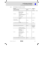
Interface description
8
7
5
6
3
4
2
1
h310_010
Fig. 2−1
ASP8 Minidin socket, 8−pin
Pin
Signal
1
Rx RS232 IN
2
Tx RS232 OUT
3
n.c.
4
RTS RS232 OUT
5
CTS RS232 IN
6
n.c.
7
Signal GND
8
+5 VCC (reserved)
n.c.
EDBPM−H315 DE/EN/FR 6.0
not connected
l
51
2
Technical data
Dimensions
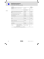
2.3
Dimensions
d
a
b
F6
F1
F7
F2
F8
F3
VWX
YZ–
+/-
7
8
9
MNO
PQR
STU
4
5
6
DEF
GHI
JKL
1
2
3
shift
·
ABC
0
± space
e
F9
F4
F10
F5
f
PgUp
Info
Help
Clr
Esc
PgDN
Enter
h315_001
Fig. 2−2
2.4
Dimensions
a [mm]
b [mm]
d [mm]
e [mm]
f [mm]
148.0
188.0
4.5
41.0
110.0
Mounting cutout
a
b
h315_002
Fig. 2−3
52
Mounting cutout
a [mm]
b [mm]
123.0
175.0
l
EDBPM−H315 DE/EN/FR 6.0
Mechanical installation
3
Labelling of operating unit
3
Mechanical installation
3.1
Labelling of operating unit
Different labels can be attached to the keypad.
ƒ The labels are only accessible when the keypad is not built in.
ƒ Ensure to have the labels ready for use before inserting the keypad into
the mounting cut−out.
LCD adj.
0
INPUT VOLTAGE: 18-32VDC 15W
FUSE 800mA
1
4 3 2 1
N.C. 24VDC
VCANShield
CAN+
N.C.
2
1 2 3 4 5
ASP8
h315_009
Fig. 3−1
Keypad labelling
0
1
2
Name of the company
Name of the machine
5 function keys (programmable)
For labelling, proceed as follows:
1. Pull label 0, 1, or 2 out of the slot for labelling.
2. After the new label has been written, push it back into the slot.
EDBPM−H315 DE/EN/FR 6.0
l
53
3
Mechanical installation
Mounting of the operating unit
3.2
Mounting of the operating unit
The dimensions for the mounting cut−out can be found in the "Technical data"
(¶ 52)
0
1
h315_006
1. Insert operating unit 0 with seal 1 into the mounting cut−out.
2
2
h315_010
2. Insert mounting clamps 2 into the slots at the operating unit.
54
l
EDBPM−H315 DE/EN/FR 6.0
Mechanical installation
3
Mounting of the operating unit
3
3
h315_011
3. Tighten the screws 3 against the mounting board.
EDBPM−H315 DE/EN/FR 6.0
l
55
4
Electrical installation
Supply voltage connection
4
Electrical installation
(
Stop!
ƒ Damage of units connected. Connect the PE conductor as shown
in the figure!
ƒ Wire the operating unit only when no voltage is applied!
4.1
Supply voltage connection
L1
N
PE
LCD adj.
INPUT VOLTAGE: 18-32VDC 15W
FUSE 800mA
4 3 2 1
~
N.C.
24VDC
–
VCANShield
CAN+
N.C.
+18...32VDC
ASP8
12 3 4 5
h315_003
Fig. 4−1
Supply voltage connection
Terminal assignment
Terminal
Identification
Explanation
1
+24 VDC
Supply voltage (DC +18 V ... 32 V)
2
0 VDC
GND supply voltage, reference potential
3
n.c.
Not connected
4
56
PE potential
l
EDBPM−H315 DE/EN/FR 6.0
Electrical installation
4
Wiring of the system bus (CAN)
4.2
Wiring of the system bus (CAN)
Principle structure
A2
A 1 (H315)
-V
CAN- Shield CAN+ N.C.
CG LO HI
An
CG LO HI
CG LO HI
CG LO HI
120
120
h315_004
Fig. 4−2
Wiring of system bus (CAN)
A1
A2
An
Node 1
Node 2
Node n
Connection
LCD adj.
INPUT VOLTAGE: 18-32VDC 15W
FUSE 800mA
VCANShield
CAN+
N.C.
N.C.
24VDC
4 3 2 1
ASP8
12 3 4 5
CAN-GND
CAN-LOW
CAN-HIGH
h315_017
Fig. 4−3
EDBPM−H315 DE/EN/FR 6.0
System bus (CAN) connection
l
57
4
Electrical installation
Wiring of the system bus (CAN)
Terminal assignment
(
Stop!
Connect a 120 W terminating resistor to the first and last bus device.
Terminal
Identification
Explanation
1
V−
GND
Reference potential
2
CAN−
LO
System bus LOW (data line)
3
Shield
4
CAN+
5
n.c.
Connect the shield of the system bus cable
HI
System bus HIGH (data line)
Not connected
For the use of the transmission cable, follow our recommendations:
Specification of the transmission cable
58
Total length
£ 300 m
£ 1000 m
Cable type
LIYCY 2 x 2 x 0.5 mm2
(paired with shielding)
CYPIMF 2 x 2 x 0.5 mm2
(paired with shielding)
Cable resistance
£ 80 W/km
£ 80 W/km
Capacitance per unit
length
£ 130 nF/km
£ 60 nF/km
l
EDBPM−H315 DE/EN/FR 6.0
Commissioning
5
Initial switch−on
5
Commissioning
5.1
Initial switch−on
Commissioning requires a complete wiring of the system bus.
Before switching on the supply voltage, check ...
ƒ the complete wiring for completeness and short circuit,
ƒ whether the bus system is terminated at the first and last physical node.
EDBPM−H315 DE/EN/FR 6.0
l
59
5
Commissioning
Project transfer to the operating unit
Connecting operating unit and PC
5.2
Project transfer to the operating unit
5.2.1
Connecting operating unit and PC
(
Stop!
Only connect PC and operating unit when the units are switched off!
LCD adj.
INPUT VOLTAGE: 18-32VDC 15W
FUSE 800mA
4 3 2 1
VCANShield
CAN+
N.C.
N.C. 24VDC
ASP8
1 2 3 4 5
l
HMI D
esigne
r
2
1
0
h315_005
Fig. 5−1
Connecting operating unit and PC
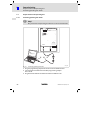
1. Plug the programming adapter EPZ−H111 0 onto the ASP8 interface.
2. Connect download cable EPZ−H110 1 to programming adapter
EPZ−H111 0.
3. Plug download cable EPZ−H110 1 onto COM1 or COMx 2 at PC.
60
l
EDBPM−H315 DE/EN/FR 6.0
Commissioning
5
Project transfer to the operating unit
Project download
5.2.2
Project download
)
Note!
In the »HMI Designer« you can select whether you want to update
the firmware at the time the project is loaded.
The firmware must always be updated with the first download of a
project to the operating unit or after an update of the
»HMI Designer« planning tool.
I
Tip!
Sample projects for the operating unit can be found in the
»HMI Designer« planning tool under File W Open... W Samples.
EDBPM−H315 DE/EN/FR 6.0
l
61
5
Commissioning
Project transfer to the operating unit
Disconnecting from the PC
Boot forced
ENTER to download
System autotest OK
F6
F1
VWX
F7
F2
YZ–
F8
F3
+/-
7
8
9
MNO
PQR
STU
4
5
6
DEF
GHI
JKL
1
shift
2
ABC
0
F9
F4
F10
F5
PgUp
Info
Help
PgDN
3
·
± space
Clr
Esc
Enter
0
h315_007
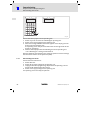
How to download a project into the operating unit:
1. Switch on your PC and start the "HMI Designer" planning tool.
2. Switch on the supply voltage for the operating unit.
3. When the message ENTER to download" appears on the display, press the
enter key 0 of the operating unit.
The operating unit is ready to receive data when the message Boot forced"
appears on the display.
4. Load the desired project from the HMI Designer into the operating unit.
– See "HMI Designer − Getting started" Manual.
After the download, the operating unit is ready for operation and can exchange
data with other stations via the system bus (CAN).
5.2.3
Disconnecting from the PC
How to disconnect from the PC:
1. Switch off the PC.
2. Switch off the supply voltage for the operating unit.
3. Unplug the EPZ−H111 programming adapter from the operating unit and
the EPZ−H110 download cable from the PC.
4. Switch on the supply voltage for the operating unit.
The operating unit is now ready for operation.
62
l
EDBPM−H315 DE/EN/FR 6.0
Commissioning
5
Status messages of the operating unit
5.3
Status messages of the operating unit
You can always query the status of the keypad and get information about:
ƒ The serial interface
ƒ The name of the loaded driver
ƒ The version of the loaded driver
ƒ The network address of the keypad
ƒ The last error
If you want to ...
A
Press keys ...
query the status of the operating unit
Example
Serial: NET
Driver: Can Lenze S
Ver. : 1.03
Up/ Down : next page
shift
2x
B
select the next status page
PgUp
PgDN
or
Addr. : FROM PRJ:010
Error : NO ERROR
Up/ Down : next page
C
5.4
close the status display.
Clr
Esc
Contrast setting
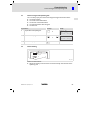
0
LCD adj.
INPUT VOLTAGE: 18-32VDC 15W
FUSE 800mA
4 3 2 1
N.C. 24VDC
h315_012
How to set the contrast:
ƒ Adjust the display contrast with the trimmer LCD adj. 0 at the back of the
operating unit.
EDBPM−H315 DE/EN/FR 6.0
l
63
6
Operation
Key functions
6
Operation
6.1
Key functions
Keys
Function
Description
<F1> ... <F5>
Execute function of F1 ... F5
(programmable keys)
<F6> ... <F10>
Execute function of F6 ... F10
(programmable keys)
<0> ... <9>
<ABC> ... <YZ—>, <+/−>
Alphanumerical keys for entering data
·
<± space>
Enter sign or space
·
<·>
Enter floating point
<Esc>
Abort parameter entry; quit help, information,
and status messages
<Clr>
Parameter level: Restores the original value
while the data is entered
PgUp
<PgUp>
<Up arrow>
Menu level: Go to previous page
Parameter level: Select previous dynamic text
PgDN
<PgDn>
<Down arrow>
Menu level: Go to next page
Parameter level: Select next dynamic text
<Left arrow>
Menu level: Place cursor on previous field
Parameter level: Place cursor on previous digit
<Right arrow>
Menu level: Place cursor on next field
Parameter level: Place cursor on next digit
<Enter>
Select parameter to enter a value
Accept the entered value
<Help>
Call up help text
<Info>
Call up info text
F6
F1
shift
+
F6
F1
ABC
0
...
...
...
F10
F5
F10
F5
+/-
9
±space
shift
+
±space
Clr
Esc
shift
+
Clr
Esc
Enter
Help
Info
)
Note!
The function keys (Fx) can be programmed using the »HMI
Designer« software.
ƒ Lenze setting: Without function.
64
l
EDBPM−H315 DE/EN/FR 6.0
Operation
6
Data input
6.2
Data input
Data input and data modification are described step−by−step using examples.
If you want to ...
A
Press keys ...
select a menu.
or
B
select a page.
C
place the cursor on the previous or next
field.
D
activate the parameter level.
l The cursor is placed on the right digit.
l In dynamic text fields, the cursor is
placed on the left character (see step
I).
E
Example
F6
F1
shift
+
F6
F1
PgUp
...
...
or
F10
F5
F10
F5
PgDN
or
Enter
Feld 1
Feld 2
Feld 3
ON
-9876
1A3F
Feld 1
Feld 2
Feld 3
ON
-9876
1A3F
Feld 1
Feld 2
Feld 3
ON
0001
1A3F
Feld 1
Feld 2
Feld 3
ON
0012
1A3F
Feld 1
Feld 2
Feld 3
ON
012.
1A3F
Feld 1
Feld 2
Feld 3
ON
-12.34
1A3F
enter a completely new value.
1. Change to the parameter level (see
step D).
2. Leave the cursor on the right digit
3. Enter the value of the first digit.
– All other positions will be set to
zero.
– The digit entered will shift one
place to the left.
ABC
0
4. Enter the value for the next digit.
– The digit entered will shift one
place to the left.
ABC
0
5. If necessary, insert a point.
TIP! Points can only be inserted if the
field is defined as Floating Point"
(see HMI Designer" planning tool).
6. Repeat step 4. until the value is
complete.
shift
+
·
±space
·
7. If necessary, enter a sign.
±space
8. Confirm the input.
– The cursor changes to the menu
level.
EDBPM−H315 DE/EN/FR 6.0
...
+/-
...
ABC
9
0
Enter
l
65
6
Operation
Data input
If you want to ...
F
Press keys ...
Example
change a digit.
1. Change to the parameter level (see
step D).
2. Select the desired digit.
G
3. Change the digit.
ABC
4. Confirm the input.
– The cursor changes to the menu
level.
Enter
0
4. Enter the value of the next digit (e.g.
D").
– The digit entered will shift one
place to the left.
5. Repeat step 4. until the value is
complete.
6. Confirm the input.
– The cursor changes to the menu
level.
ABC
0
ABC
0
ON
-1934
1A3F
Feld 1
Feld 2
Feld 3
ON
-1934
1A3F
Feld 1
Feld 2
Feld 3
ON
-1934
000B
Feld 1
Feld 2
Feld 3
ON
-1934
00BD
Feld 1
Feld 2
Feld 3
ON
-1934
1C3F
Feld 1
Feld 2
Feld 3
ON
-9876
1A3F
9
3x
2x
change a hexadecimal digit.
1. Change to the parameter level (see
step D).
3. Change the digit (e.g. C").
4. Confirm the input.
– The cursor changes to the menu
level.
or
ABC
0
4x
Enter
change a dynamic text field.
1. Select the text.
2. Confirm the input.
– The cursor changes to the menu
level.
66
+/-
Feld 1
Feld 2
Feld 3
Enter
2. Select the desired digit.
I
...
enter a new hexadecimal value.
1. Change to the parameter level (see
step D).
2. Leave the cursor on the right digit.
3. Enter the value of the first digit (e.g.
B").
– All other positions will be set to
zero.
– The digit entered will shift one
place to the left.
H
or
Help
á
or
Info
â
Enter
l
EDBPM−H315 DE/EN/FR 6.0
Operation
6
Calling up information messages
6.3
Calling up information messages
ƒ Information messages
– are texts which appear because of a certain event (e.g. if an actual value
exceeds a limit),
– can only be called up as long as the triggering event is active.
– must have been programmed in the HMI Designer" planning tool.
– can have a maximum length of 2 lines × 20 characters.
ƒ The second to last line contains a programmable message field. This field
indicates the numerical size of the variable that has activated the
message.
ƒ The LED in the
Info
key will flash if an information message is available.
If you want to ...
A
Press keys ...
call up an information message.
l Information messages called up for the first
time are marked by **.
B
select the previous or next information
message.
C
close the information message.
6.4
Example
Druck uebersteigt
die Sicherheitsgrenze
125.5
Info
PgUp
or
PgDN
**
Wasserstand unterhalb
der Arbeitsschwelle
40
Clr
Esc
Calling up help messages
ƒ Help messages
– can be assigned to pages or information messages.
– contain useful notes to make handling easier.
– must have been programmed in the HMI Designer" planning tool.
ƒ The LED in the
If you want to ...
A
call up a help message.
B
close a help message.
EDBPM−H315 DE/EN/FR 6.0
Help
key will flash if a help message is available.
Press keys ...
Example
Help
Clr
Esc
l
67
7
Troubleshooting and fault elimination
Fault messages
7
Troubleshooting and fault elimination
7.1
Fault messages
Call up the status messages of the operating unit to display the fault message
that occurred last. (¶ 63)
Display
Fault
Cause
Remedy
NO ERROR
No fault
−
−
PR ERROR
Faulty data
exchange
Connection between operating
unit and PC is faulty
l
COM BROK
Communication
interrupted
Serial data cable between
operating unit and PC is
defective or not correctly
connected
l
ASIC ko1
ASIC ko2
ASIC ko3
ASIC ko4
Communication
with system
bus (CAN)
interrupted
l
l
Faulty wiring (e. g. polarity)
of the system bus
Faulty parameterisation of
interface (baud rate,
address, identifier)
l
l
l
l
Check that the connections are
firmly seated.
Check cable for damages
Check Sub−D connector for correct
connection and firm seating.
Replace serial data cable
Check wiring of system bus (CAN)
(^ 57)
Check parameter setting (^ HMI
Designer − Getting started).
RESET
SDOERR 6
SDOERR 5
SDOERR 3
68
l
EDBPM−H315 DE/EN/FR 6.0
Maintenance
8
8
Maintenance
The operating unit is maintenance−free if all operating conditions described in
these Instructions are observed. (¶ 47)
ƒ Clean the operating unit with denatured ethyl alcohol.
ƒ If you use any other cleaning agents, please observe the information
given in the table in chapter 9.1. (¶ 70)
EDBPM−H315 DE/EN/FR 6.0
l
69
9
Appendix
Chemical resistance
9
Appendix
9.1
Chemical resistance
(
Stop!
The resistance of the operating unit’s surface against acid food (e.g.
tomato juice, lemon juice) is low. For this reason remove soilings
immediately, otherwise the surface may be damaged.
The following table shows the resistance of the surfaces (keyboard, display,
touchscreen) to the listed chemicals.
For EPM−H5xx and EPM−H6xx operating units, Lenze offers protective foils with
an improved resistance against the listed chemicals.
Operating unit
EPM−H3xx
EPM−H4xx
EPM−H5xx
EPM−H6xx
With
protective
foil
Substance
L
L
L
J
L
L
J
L
L
Benzene
J
L
L
J
Benzole
J
J
L
J
Benzyl alcohol
L
L
Diesel oil
J
J
J
J
Ethanol
L
L
L
J
Ethylene glycol
L
L
L
L
L
L
L
Acetic acid
³ 5 % < 50 %
Acetone
Ammonia
Formic acid
³2%
³ 50 %
High−pressure and
temperature > 100 °C
Hydrochloric acid
³ 10 %
L
L
Hydrogen peroxide
³ 25 %
L
L
Hypochlorous acidic
natron
³ 20 %
L
L
Isopropanol
J
J
L
J
Methanol
J
J
L
L
L
Mineral acids
Concentrated
L
L
Nitric acid
³ 5 % < 10 %
L
L
L
J
L
J
Methylene chloride
Perchloroethylene
70
l
EDBPM−H315 DE/EN/FR 6.0
Appendix
9
Chemical resistance
Operating unit
EPM−H3xx
EPM−H4xx
EPM−H5xx
EPM−H6xx
With
protective
foil
Substance
Phosphoric acid
³ 30 %
L
L
L
L
Pickling solution
Concentrated
L
L
L
Pure acetic acid
Sodium hydroxide
³2%
L
L
Sodium hydroxide
³ 50 %
L
L
L
Sulphuric acid
³ 50 %
L
L
L
L
Toluol
J
J
L
J
Trichloroethylene
L
J
EPM−H3xx
EPM−H4xx
EPM−H5xx
EPM−H6xx
J
L
EDBPM−H315 DE/EN/FR 6.0
EPM−H310, EPM−H312, EPM−H315
EPM−H410
EPM−H502, EPM−H505, EPM−H507, EPM−H510, EPM−H515, EPM−H520,
EPM−H521, EPM−H525
EPM−H605, EPM−H606
Surface resists, no visible damage
Surface does not resist, visible damage
Not tested
l
71
9
Appendix
Index
9.2
Index
A
F
Ambient conditions, Climatic, 47
Fault messages, 68
B
G
Baud rate, System bus (CAN), 48
General data, 47
C
H
Cable resistance, 58
Help messages, 67
Cable type, 58
Human Machine Interface, 45
Capacitance per unit length, 58
Humidity, 47
Chemical resistance, 70
Commissioning, 59
− Initial switch−on, 59
Connecting the supply voltage, 56
Connection, Electrical, 48
Contrast, setting, 63
I
Information messages, 67
Initial switch−on, 59
Installation, system bus (CAN), 57
Installation, electrical, 56
Controller, 45
Installation, electrical , connecting the supply
voltage, 56
D
Installation, mechanical, 53
Data, input, 65
K
DC voltage supply, 48
Key functions, 64
Definition of notes used, 46
Definitions, 45
M
Display, 48
Maintenance, 69
− contrast setting, 63
Mechanical installation, 53
E
Electrical data, 48
Electrical installation, 56
Memory, 48
Mounting conditions, Weight, 47
Mounting cutout, 52
− Connecting the supply voltage, 56
72
l
EDBPM−H315 DE/EN/FR 6.0
Appendix
9
Index
N
Project
Notes, definition, 46
− Download, 61
− Project transfer to the operating unit, 60
O
S
Operating conditions, 47
Safety instructions
− Ambient conditions, Climatic, 47
− Humidity, 47
− Mounting conditions, Weight, 47
− definition, 46
− layout, 46
Status messages, 63
Operating unit
−
−
−
−
−
−
−
−
−
−
Switch on, initial, 59
Calling up help messages, 67
Calling up information messages, 67
Connecting with the PC, 60
Data input, 65
Disconnecting from the PC, 62
Interface description, 51
Key functions, 64
Parameters, 49
Project transfer, 60
Status messages, 63
System bus (CAN)
− Baud rate, 48
− Wiring, 57
T
Technical data, 47
Operation, 64
P
Parameters, 49
PC
− Connecting with the operating unit, 60
− Disconnecting from the operating unit, 62
DC voltage supply, 48
Display, 48
Electrical connection, 48
Electrical data, 48
Interface description, 51
Memory, 48
Mounting cutout, 52
Power consumption, 48
System bus (CAN), 48
Troubleshooting, fault messages, 68
Troubleshooting and fault elimination, 68
Power consumption, 48
EDBPM−H315 DE/EN/FR 6.0
−
−
−
−
−
−
−
−
−
l
73
Légende
Pos.
Description
Fonction
0
Bornier 4 bornes
Alimentation 24 V CC
1
Trimmer LCD ADJ
Réglage du contraste de l’écran
2
Bornier 5 bornes
Bus Système CAN
3
Prise Minidin 8 broches
Port série (ASP) pour PC ou API
74
l
EDBPM−H315 DE/EN/FR 6.0
Validité :
Unité de commande EPM−H315 à partir de la version ci−dessous (voir plaque signalétique) :
Type
EPM−H315
1A
10
Série d’appareils
EPM
Unité de commande
Version matérielle
Version logicielle
EDBPM−H315 DE/EN/FR 6.0
l
75
Historique du document
Nouveautés / Modifications
Numéro de
documentation
Version
Description
.>@E
6.0
04/2009
TD23
Nouvelle édition en raison de la nouvelle
organisation de l’entreprise
13238588
5.0
02/2008
TD23
Nouvelle raison sociale : Lenze Digitec Controls
GmbH
00473989
4.0
05/2003
TD23
Révision, rectification des erreurs
00457281
3.0
08/2002
TD23
Changement du nom de société
00418422
2.0
08/2001
TD23
Texte entièrement revu pour la série
00415798
1.0
06/2000
TD23
Première édition pour essais sur le terrain
0Fig. 0Tab. 0
I
Conseil !
Les mises à jour de logiciels et les documentations relatives aux produits Lenze
sont disponibles dans la zone "Téléchargements" du site Internet :
http://www.Lenze.com
© 2009 Lenze Automation GmbH, Grünstraße 36, D−40667 Meerbusch
76
l
EDBPM−H315 DE/EN/FR 6.0
Sommaire
1
2
Avant−propos et généralités . . . . . . . . . . . . . . . . . . . . . . . . . . . . . . . . . . . . . . . .
79
1.1
1.2
1.3
1.4
Comment utiliser ces instructions de mise en service . . . . . . . . . . . .
Terminologie . . . . . . . . . . . . . . . . . . . . . . . . . . . . . . . . . . . . . . . . . . . . . .
Equipement livré . . . . . . . . . . . . . . . . . . . . . . . . . . . . . . . . . . . . . . . . . . .
Consignes utilisées . . . . . . . . . . . . . . . . . . . . . . . . . . . . . . . . . . . . . . . . .
79
79
79
80
Spécifications techniques . . . . . . . . . . . . . . . . . . . . . . . . . . . . . . . . . . . . . . . . .
81
2.1
2.2
Caractéristiques générales et conditions d’utilisation . . . . . . . . . . .
Caractéristiques électriques . . . . . . . . . . . . . . . . . . . . . . . . . . . . . . . . . .
2.2.1
Caractéristiques de l’unité de commande . . . . . . . . . . . . .
2.2.2
Affectation de la prise . . . . . . . . . . . . . . . . . . . . . . . . . . . . .
Encombrements . . . . . . . . . . . . . . . . . . . . . . . . . . . . . . . . . . . . . . . . . . .
Encoche de montage . . . . . . . . . . . . . . . . . . . . . . . . . . . . . . . . . . . . . . . .
81
82
83
85
86
86
Installation mécanique . . . . . . . . . . . . . . . . . . . . . . . . . . . . . . . . . . . . . . . . . . . .
87
3.1
3.2
Marquage de l’unité de commande . . . . . . . . . . . . . . . . . . . . . . . . . . .
Montage de l’unité de commande . . . . . . . . . . . . . . . . . . . . . . . . . . . .
87
88
Installation électrique . . . . . . . . . . . . . . . . . . . . . . . . . . . . . . . . . . . . . . . . . . . . .
90
4.1
4.2
Raccordement de la tension d’alimentation . . . . . . . . . . . . . . . . . . . .
Câblage du Bus Système CAN . . . . . . . . . . . . . . . . . . . . . . . . . . . . . . . .
90
91
Mise en service . . . . . . . . . . . . . . . . . . . . . . . . . . . . . . . . . . . . . . . . . . . . . . . . . . .
93
2.3
2.4
3
4
5
5.1
5.2
5.3
5.4
6
Première mise en service . . . . . . . . . . . . . . . . . . . . . . . . . . . . . . . . . . . .
93
Téléchargement d’un projet sur l’unité de commande . . . . . . . . . . . .
94
5.2.1
Etablissement de la liaison entre l’unité de commande et le PC
94
5.2.2
Téléchargement du projet . . . . . . . . . . . . . . . . . . . . . . . . . .
95
5.2.3
Déconnexion du PC . . . . . . . . . . . . . . . . . . . . . . . . . . . . . . .
96
Messages d’état de l’unité de commande . . . . . . . . . . . . . . . . . . . . . .
97
Réglage du contraste . . . . . . . . . . . . . . . . . . . . . . . . . . . . . . . . . . . . . . .
97
Utilisation . . . . . . . . . . . . . . . . . . . . . . . . . . . . . . . . . . . . . . . . . . . . . . . . . . . . . . .
6.1
6.2
6.3
6.4
7
i
98
Fonction des touches . . . . . . . . . . . . . . . . . . . . . . . . . . . . . . . . . . . . . . .
Saisie des données . . . . . . . . . . . . . . . . . . . . . . . . . . . . . . . . . . . . . . . . .
Affichage d’un message d’information . . . . . . . . . . . . . . . . . . . . . . . .
Recherche d’une rubrique d’aide . . . . . . . . . . . . . . . . . . . . . . . . . . . . . .
98
99
101
101
Détection et élimination des défauts . . . . . . . . . . . . . . . . . . . . . . . . . . . . . . . .
102
7.1
102
Messages d’erreur . . . . . . . . . . . . . . . . . . . . . . . . . . . . . . . . . . . . . . . . . .
EDBPM−H315 DE/EN/FR 6.0
l
77
i
Sommaire
8
Maintenance . . . . . . . . . . . . . . . . . . . . . . . . . . . . . . . . . . . . . . . . . . . . . . . . . . . .
103
9
Annexe . . . . . . . . . . . . . . . . . . . . . . . . . . . . . . . . . . . . . . . . . . . . . . . . . . . . . . . . .
104
9.1
9.2
104
106
78
Résistance aux produits chimiques . . . . . . . . . . . . . . . . . . . . . . . . . . . .
Index . . . . . . . . . . . . . . . . . . . . . . . . . . . . . . . . . . . . . . . . . . . . . . . . . . . . .
l
EDBPM−H315 DE/EN/FR 6.0
Avant−propos et généralités
1
Comment utiliser ces instructions de mise en service
1
Avant−propos et généralités
L’unité de commande permet d’accéder aux codes des variateurs de vitesse
Lenze, du Servo PLC 9300 et du Drive PLC, ainsi que de commander ces appareils
de façon conviviale. La communication s’effectue via le Bus Système CAN.
Grâce au logiciel HMI Designer de Lenze, la programmation de l’unité de
commande est un véritable jeu d’enfant.
1.1
Comment utiliser ces instructions de mise en service
ƒ Les présentes instructions de mise en service permettent d’utiliser en
toute sécurité l’unité de commande.
ƒ Toute personne utilisant l’unité de commande doit pouvoir consulter ces
instructions à tout instant et est tenue de respecter les indications et
consignes correspondantes.
ƒ Les instructions de mise en service doivent être complètes et lisibles en
toute circonstance.
1.2
1.3
Terminologie
Terme
Utilisé dans le présent document pour désigner
Variateur de vitesse
les convertisseurs de fréquence 8200 vector et 9300 vector, et les
servovariateurs 9300 et 9400 de Lenze
HMI
une interface homme−machine (Human Machine Interface)
Equipement livré
Equipement livré
l
l
l
l
l
l
l
IMPORTANT
1 unité de commande EPM−H315
1 document "Instructions de mise en
service"
4 colliers de fixation
4 vis M4 x 35 mm
1 joint
1 bornier 4 bornes pour le raccordement de
l’alimentation CC
1 bornier 5 bornes pour le raccordement du
Bus Système CAN
EDBPM−H315 DE/EN/FR 6.0
l
Vérifier à la réception que l’équipement livré est
conforme au bon de livraison. Aucune
réclamation ne pourra être formulée
ultérieurement.
En cas de
l dégâts visibles occasionnés par le transport :
réclamation immédiate auprès du
transporteur ;
l vices apparents/équipement incomplet :
réclamation immédiate auprès de l’agence
Lenze concernée.
79
1
Avant−propos et généralités
Consignes utilisées
1.4
Consignes utilisées
Pour indiquer des risques et des informations importantes, la présente
documentation utilise les mots et symboles suivants :
Consignes de sécurité
Présentation des consignes de sécurité
}
Danger !
(Le pictogramme indique le type de risque.)
Explication
(L’explication décrit le risque et les moyens de l’éviter.)
Pictogramme et mot associé
Explication
{
Danger !
Situation dangereuse pour les personnes en raison
d’une tension électrique élevée
Indication d’un danger imminent qui peut avoir pour
conséquences des blessures mortelles ou très graves en
cas de non−respect des consignes de sécurité
correspondantes
Danger !
Situation dangereuse pour les personnes en raison d’un
danger d’ordre général
Indication d’un danger imminent qui peut avoir pour
conséquences des blessures mortelles ou très graves en
cas de non−respect des consignes de sécurité
correspondantes
Stop !
Risques de dégâts matériels
Indication d’un risque potentiel qui peut avoir pour
conséquences des dégâts matériels en cas de
non−respect des consignes de sécurité correspondantes
}
(
Consignes d’utilisation
Pictogramme et mot associé
Explication
)
Remarque
importante !
Remarque importante pour assurer un fonctionnement
correct
Conseil !
Conseil utile pour faciliter la mise en oeuvre
I
,
80
Référence à une autre documentation
l
EDBPM−H315 DE/EN/FR 6.0
Spécifications techniques
2
Caractéristiques générales et conditions d’utilisation
2
Spécifications techniques
2.1
Caractéristiques générales et conditions d’utilisation
Caractéristiques générales
Conformité et homologation
Conformité
CE
2004/108/CE
Directive CEM
cULus
Underwriter Laboratories Inc. (File−No. E189179)
Homologations
UL
Protection des personnes et protection d’appareil
IP65 (à l’avant)
Indice de protection
CEM
Normes appliquées
pour les valeurs
limites
EN 50081−2
(1994)
Perturbations radioélectriques
EN 50082−2
(1995)
Protection contre les parasites
Conditions d’utilisation
Conditions ambiantes
Conditions climatiques
Stockage
−20 ... +60 °C
Transport
−20 ... +60 °C
Fonctionnement
0 ... +50 °C
Humidité
admissible
<85 %, sans condensation
Conditions de montage
0,7 kg
Poids
EDBPM−H315 DE/EN/FR 6.0
l
81
2
Spécifications techniques
Caractéristiques électriques
2.2
Caractéristiques électriques
Domaine
Ecran
Raccordement
électrique
Données
Type
LCD
Format de présentation
Texte
Taille d’affichage
70,4 × 20,8 mm
Lignes × caractères
4 × 20
Taille de caractères
2,95 × 4,75 mm
Taille de caractères en
mode texte
5 × 7 pixel
Polices
ASCII, Katakana
Réglage du contraste
Potentiomètre−trimmer
Rétro−éclairage
LED
Alimentation CC
+18 à 32 VCC
Puissance absorbée
15 W pour 24 VCC
Protection par fusible
Fusible pour faible intensité Æ5 × 20 mm,
800 mA / F
Protocole
Bus Système CAN
Topologie du réseau
Ligne (fermée des deux extrémités avec 120 W)
Participant au Bus Système
Maître ou esclave
Nombre maxi de
participants
63
Vitesse de transmission
[kbits/s]
20
50
125
250
500
1000
1000
500
250
80
25
Réseau :
Bus Système CAN
Longueur de bus maxi [m]
2500
Mémoire
Programme utilisateur
256 kO
Interfaces
série
ASP8 (prise Minidin 8
broches)
82
RS232
l
EDBPM−H315 DE/EN/FR 6.0
Spécifications techniques
2
Caractéristiques électriques
Caractéristiques de l’unité de commande
2.2.1
Caractéristiques de l’unité de commande
Description
Données
Opérations automatiques
[nombre]
32
Sauvegarde/reconstitution
[fonction]
proposé
[fonction]
proposé
Modifier le mot de passe
Mot de passe Login
Mot de passe Logout
Instructions
Quitter le projet
Afficher les informations projet
Afficher le répertoire de la
séquence
Choix de la langue
Mot de passe binaire
[bits]
8
SOUSTRAIRE
ENTRER
Instruction directe
avec structure valeur
ou
[fonction]
proposé
Textes dynamiques (avec les différents formats : cordon [nombre]
de bits, bit individuel ou valeur)
1024 1)
LEDs affectées à une séquence
[fonction]
proposé
Etiquettes
[fonction]
proposé
Touches de fonction configurables (touches F)
[nombre]
5 (10 fonctions
par affectation
double)
[fonction]
proposé
ET
XOR
AJOUTER
Activer bit en permanence
Désactiver bit en permanence
Inversion bit
Instruction directe avec
structure valeur
Activer bit temps réel
Fonction
Désactiver bit temps réel
Instruction interne
Sans fonction
Macro
Séquence
Désactiver la touche
Equations
[nombre]
32
Touches de saisie globales (touches E) avec fonctions
fixes
[fonction]
proposé
EDBPM−H315 DE/EN/FR 6.0
l
83
2
Spécifications techniques
Caractéristiques électriques
Caractéristiques de l’unité de commande
Description
Données
Configuration globale des touches de fonction
(touches F)
[fonction]
Messages d’information
[total/ activés
simultanément]
Registre interne
[nombre]
2048 octets
Touches de saisie locales (touches E) avec fonctions
fixes
[fonction]
proposé
Configuration locale des touches de fonction
(touches F)
[fonction]
proposé
Macros (total/instructions ´ macro)
[nombre]
1024/16
Aides aux messages
[nombre]
1024
Champ de message
[fonction]
proposé
Textes multilingues
[nombre de langues]
6
Niveaux de mot de passe
[nombre]
10
Pages
[nombre]
1024
Pages d’aide
[nombre]
1024
[nombre]
64
Messages système
[fonction]
proposé
Listes de textes
[fonction]
proposé
Temporisateur
[nombre]
32
[nombre par page]
30
Séquence : au choix
Séquence : marche/arrêt
proposé
1024/128
Variables limite et variables
linéaires de correction
Variables
1)
84
Variables numériques (DEC,
HEX, BIN, BCD)
valeur approximative limitée par la grandeur process
l
EDBPM−H315 DE/EN/FR 6.0
Spécifications techniques
2
Caractéristiques électriques
Affectation de la prise
2.2.2
Affectation de la prise
8
7
5
6
3
4
2
1
h310_010
Fig.2−1
Prise ASP8 Minidin à 8 broches
Pin
Signal
1
Rx RS232 IN
2
Tx RS232 OUT
3
N.C.
4
RTS RS232 OUT
5
CTS RS232 IN
6
N.C.
7
Signal GND
8
+5 VCC (réservé)
N.C.
EDBPM−H315 DE/EN/FR 6.0
Non connecté
l
85
2
Spécifications techniques
Encombrements
2.3
Encombrements
d
a
b
F6
F1
F7
F2
F8
F3
VWX
YZ–
+/-
7
8
9
MNO
PQR
STU
4
5
6
DEF
GHI
JKL
1
2
3
shift
ABC
0
·
± space
e
F9
F4
F10
F5
f
PgUp
Info
Help
Clr
Esc
PgDN
Enter
h315_001
Fig.2−2
2.4
Encombrements
a [mm]
b [mm]
d [mm]
e [mm]
f [mm]
148.0
188.0
4.5
41.0
110.0
Encoche de montage
a
b
h315_002
Fig.2−3
86
Encoche de montage
a [mm]
b [mm]
123.0
175.0
l
EDBPM−H315 DE/EN/FR 6.0
Installation mécanique
3
Marquage de l’unité de commande
3
Installation mécanique
3.1
Marquage de l’unité de commande
L’unité de commande permet le changement d’étiquettes.
ƒ Les étiquettes ne sont accessibles que si l’unité de commande est
démontée.
ƒ Remplir les étiquettes avant de monter l’unité de commande dans
l’encoche de montage.
LCD adj.
0
INPUT VOLTAGE: 18-32VDC 15W
FUSE 800mA
1
4 3 2 1
N.C. 24VDC
VCANShield
CAN+
N.C.
2
1 2 3 4 5
ASP8
h315_009
Fig.3−1
Etiquetage de l’unité de commande
0
1
2
Nom de la société
Désignation machine
5 touches de fonction (configurables)
Pour remplir les étiquettes :
1. Retirer l’étiquette 0, 1, ou 2 de la fente.
2. Ensuite, faire glisser l’étiquette remplie dans la fente.
EDBPM−H315 DE/EN/FR 6.0
l
87
3
Installation mécanique
Montage de l’unité de commande
3.2
Montage de l’unité de commande
Pour les cotes de l’encoche de montage, se reporter au chapitre Spécifications
techniques. (¶ 86)
0
1
h315_006
1. Glisser l’unité de commande 0 avec le joint 1 dans l’encoche de montage.
2
2
h315_010
2. Placer les colliers de fixation 2 dans les ouvertures prévues à cet effet.
88
l
EDBPM−H315 DE/EN/FR 6.0
Installation mécanique
3
Montage de l’unité de commande
3
3
h315_011
3. Visser la plaque de montage à l’aide des vis 3.
EDBPM−H315 DE/EN/FR 6.0
l
89
4
Installation électrique
Raccordement de la tension d’alimentation
4
Installation électrique
(
Stop !
ƒ Risque d’endommagement des appareils connectés. Relier le
conducteur PE uniquement comme indiqué sur l’illustration !
ƒ Ne procéder au câblage de l’unité de commande qu’en l’absence
de tension !
4.1
Raccordement de la tension d’alimentation
L1
N
PE
LCD adj.
INPUT VOLTAGE: 18-32VDC 15W
FUSE 800mA
4 3 2 1
~
N.C.
24VDC
–
VCANShield
CAN+
N.C.
+18...32VDC
ASP8
12 3 4 5
h315_003
Fig.4−1
Raccordement de la tension d’alimentation
Affectation des bornes
Borne
Désignation
Explication
1
+24 V CC
Tension d’alimentation (+18 V ... 32 V CC)
2
0 V CC
GND tension d’alimentation, potentiel de référence
3
N.C.
Non raccordé
4
90
Potential PE
l
EDBPM−H315 DE/EN/FR 6.0
Installation électrique
4
Câblage du Bus Système CAN
4.2
Câblage du Bus Système CAN
Principe de câblage
A2
A 1 (H315)
-V
CAN- Shield CAN+ N.C.
CG LO HI
An
CG LO HI
CG LO HI
CG LO HI
120
120
h315_004
Fig.4−2
Câblage du Bus Système CAN
A1
A2
An
Participant au bus 1
Participant au bus 2
Participant au bus n
Raccordement
LCD adj.
INPUT VOLTAGE: 18-32VDC 15W
FUSE 800mA
VCANShield
CAN+
N.C.
N.C.
24VDC
4 3 2 1
ASP8
12 3 4 5
CAN-GND
CAN-LOW
CAN-HIGH
h315_017
Fig.4−3
EDBPM−H315 DE/EN/FR 6.0
Raccordement Bus Système CAN
l
91
4
Installation électrique
Câblage du Bus Système CAN
Affectation des bornes
(
Stop !
Raccorder une résistance d’extrémité 120 W sur le premier et le
dernier participant au bus.
Borne
Désignation
Explication
1
V−
GND
Potentiel de référence
2
CAN−
LO
Bus Système LOW (ligne de données)
3
Shield
4
CAN+
5
N.C.
Poser le blindage du câble bus
HI
Bus Système HIGH (ligne de données)
Non raccordé
Nous vous recommandons d’utiliser les câbles suivants :
Spécifications du câble de transmission
92
Longueur totale
£ 300 m
£ 1000 m
Type de câble
LIYCY 2 x 2 x 0,5 mm2
(paire blindée)
CYPIMF 2 x 2 x 0,5 mm2
(paire blindée)
Résistance de câble
£ 80 W/km
£ 80 W/km
Capacité de câble
£ 130 nF/km
£ 60 nF/km
l
EDBPM−H315 DE/EN/FR 6.0
Mise en service
5
Première mise en service
5
Mise en service
5.1
Première mise en service
Pour la mise en service, il est impératif que le Bus Système soit correctement
raccordé.
Avant la mise sous tension, vérifier ...
ƒ le câblage dans son intégralité pour éviter un court−circuit,
ƒ si des résistances d’extrémité de bus sont raccordées au premier et au
dernier participant au bus.
EDBPM−H315 DE/EN/FR 6.0
l
93
5
Mise en service
Téléchargement d’un projet sur l’unité de commande
Etablissement de la liaison entre l’unité de commande et le PC
5.2
Téléchargement d’un projet sur l’unité de commande
5.2.1
Etablissement de la liaison entre l’unité de commande et le PC
(
Stop !
Ne relier le PC à l’unité de commande qu’en l’absence de tension !
LCD adj.
INPUT VOLTAGE: 18-32VDC 15W
FUSE 800mA
4 3 2 1
VCANShield
CAN+
N.C.
N.C. 24VDC
ASP8
1 2 3 4 5
l
HMI D
esigne
r
2
1
0
h315_005
Fig.5−1
Etablissement de la liaison entre l’unité de commande au PC
1. Enficher l’adaptateur de paramétrage EPZ−H111 0 dans la prise ASP8.
2. Relier le câble de téléchargement EPZ−H110 1 avec l’adaptateur
EPZ−H111 0.
3. Enficher le câble de téléchargement EPZ−H110 1 dans le port COM1 ou
COMx 2du PC.
94
l
EDBPM−H315 DE/EN/FR 6.0
Mise en service
5
Téléchargement d’un projet sur l’unité de commande
Téléchargement du projet
5.2.2
Téléchargement du projet
)
Remarque importante !
L’outil de conception "HMI Designer" vous permet de déterminer si,
le micrologiciel doit être actualisé simultanément au chargement du
projet.
Il faut toujours procéder à l’actualisation du micrologiciel lors du
premier téléchargement d’un projet sur l’unité de commande et
après une mise à jour de l’outil de conception "HMI Designer".
I
Conseil !
Pour les exemples de projet de l’unité de commande, voir l’outil de
conception "HMI Designer" Fichier W Ouvrir... W Samples (exemples).
EDBPM−H315 DE/EN/FR 6.0
l
95
5
Mise en service
Téléchargement d’un projet sur l’unité de commande
Déconnexion du PC
Boot forced
ENTER to download
System autotest OK
F6
F1
VWX
F7
F2
YZ–
F8
F3
+/-
7
8
9
MNO
PQR
STU
4
5
6
DEF
GHI
JKL
1
shift
2
ABC
0
F9
F4
F10
F5
PgUp
Info
Help
PgDN
3
·
± space
Clr
Esc
Enter
0
h315_007
Pour charger un projet sur l’unité de commande :
1. Mettre le PC sous tension et démarrer l’outil de conception
"HMI Designer".
2. Mettre l’unité de commande sous tension.
3. Dès que ENTER to download" s’affiche, appuyer sur la touche Entrée 0 de
l’unité de commande.
L’unité de commande est prête à recevoir des données dès que le message
Boot forced" apparaît.
4. Télécharger le projet souhaité de HMI Designer vers l’unité de commande.
– Voir aussi le manuel HMI Designer − Premiers pas".
Après le téléchargement, l’unité de commande est prête à fonctionner et peut
échanger des données via le Bus Système (CAN) avec les participants raccordés.
5.2.3
Déconnexion du PC
Pour couper la liaison avec le PC :
1. Mettre le PC hors tension.
2. Mettre l’unité de commande hors tension.
3. Retirer l’adaptateur EPZ−H111 de l’unité de commande et le câble de
téléchargement EPZ−H110 du PC.
4. Mettre l’unité de commande sous tension.
L’unité de commande est prête à fonctionner.
96
l
EDBPM−H315 DE/EN/FR 6.0
Mise en service
5
Messages d’état de l’unité de commande
5.3
Messages d’état de l’unité de commande
L’état de l’unité de commande peut être affiché à tout instant. Les informations
suivantes peuvent être affichées :
ƒ l’interface série (Serial),
ƒ le nom du pilote chargé (Driver),
ƒ la version du pilote chargé (Ver.),
ƒ l’adresse réseau de l’unité de commande (Addr.),
ƒ la dernière erreur en date (Error).
Pour ...
A
appuyer sur les touches ...
connaître l’état de l’unité de commande
Serial: NET
Driver: Can Lenze S
Ver. : 1.03
Up/ Down : next page
shift
2x
B
sélectionner la page d’état suivante
PgUp
PgDN
ou
Exemple
Addr. : FROM PRJ:010
Error : NO ERROR
Up/ Down : next page
C
5.4
fermer l’affichage d’état
Clr
Esc
Réglage du contraste
0
LCD adj.
INPUT VOLTAGE: 18-32VDC 15W
FUSE 800mA
4 3 2 1
N.C. 24VDC
h315_012
Pour régler le contraste :
ƒ Les contrastes de l’affichage peuvent être réglés sur la face arrière de
l’unité de commande à l’aide du trimmer LCD adj. 0.
EDBPM−H315 DE/EN/FR 6.0
l
97
6
Utilisation
Fonction des touches
6
Utilisation
6.1
Fonction des touches
Touches
Fonction
Description
<F1> à <F5>
Exécuter la fonction de F1 à F5
(touches configurables).
<F6> à <F10>
Exécuter la fonction de F6 à F10
(touches configurables).
<0> à <9>
<ABC> à <YZ—>, <+/−>
Touches alphanumériques pour la saisie de
données
·
<± space>
Entrer le signe ou le caractère espace.
·
<·>
Entrer la virgule flottante.
<Esc>
Abandonner la saisie de paramètres ; quitter les
messages d’aide, d’information et d’état.
<Clr>
Niveau paramètres : remettre le paramètre à la
valeur initiale.
PgUp
<PgUp>
<Flèche vers le haut>
Niveau menu : passer à la page précédente.
Niveau paramètres : sélectionner le texte
dynamique précédent.
PgDN
<PgDn>
<Flèche vers le bas>
Niveau menu : passer à la page suivante.
Niveau paramètres : sélectionner le texte
dynamique suivant.
<Flèche vers la gauche>
Niveau menu : placer le curseur sur le champ
précédent.
Niveau paramètres : placer le curseur sur le
champ précédent.
<Flèche vers la droite>
Niveau menu : placer le curseur sur le champ
suivant.
Niveau paramètres : placer le curseur sur le
champ suivant.
<Enter>
Sélectionner un code pour entrer une valeur.
Valider la valeur entrée.
<Help>
Afficher l’aide.
<Info>
Afficher un message d’information.
F6
F1
shift
+
F6
F1
ABC
0
à
à
à
F10
F5
F10
F5
+/-
9
±space
shift
+
±space
Clr
Esc
shift
+
Clr
Esc
Enter
Help
Info
)
Remarque importante !
Les touches de fonction (Fx) peuvent être programmées à l’aide du
logiciel "HMI Designer".
ƒ Réglage Lenze : pas de fonction.
98
l
EDBPM−H315 DE/EN/FR 6.0
Utilisation
6
Saisie des données
6.2
Saisie des données
L’ordre chronologique pour la saisie et la modification des données est décrit à
l’aide d’un exemple.
Pour ...
A
appuyer sur les touches ...
sélectionner un menu
F6
F1
ou
B
sélectionner une page
C
placer le curseur sur le champ suivant ou
le champ précédent
D
passer au niveau paramètres
l Le curseur est placé sur le chiffre
droit.
l Dans une zone de description
dynamique, le curseur est placé sur le
caractère gauche (voir I).
E
shift
+
F6
F1
PgUp
à
à
ou
Exemple
F10
F5
F10
F5
PgDN
ou
Enter
Feld 1
Feld 2
Feld 3
ON
-9876
1A3F
Feld 1
Feld 2
Feld 3
ON
-9876
1A3F
Feld 1
Feld 2
Feld 3
ON
0001
1A3F
Feld 1
Feld 2
Feld 3
ON
0012
1A3F
Feld 1
Feld 2
Feld 3
ON
012.
1A3F
Feld 1
Feld 2
Feld 3
ON
-12.34
1A3F
entrer une valeur nouvelle
1. Passer au niveau paramètres (voir D).
2. Laisser le curseur sur le chiffre droit.
3. Entrer la valeur de la première
position.
– Toutes les autres positions sont
mises à zéro.
– Le chiffre entré est placé à gauche
d’une position.
ABC
0
4. Entrer la valeur de la position
suivante.
– Les chiffres entrés sont placés à
gauche d’une position.
ABC
0
5. Le cas échéant, entrer une virgule.
Conseil ! Pour pouvoir insérer une
virgule flottante, le champ doit être
défini comme "floating point" (voir
outil de conception "HMI Designer").
6. Recommencer par 4. jusqu’à ce que la
valeur complète soit entrée.
shift
+
·
±space
·
7. Le cas échéant, entrer un signe.
±space
8. Valider.
– Le curseur passe au niveau menu.
EDBPM−H315 DE/EN/FR 6.0
à
+/-
à
ABC
9
0
Enter
l
99
6
Utilisation
Saisie des données
Pour ...
F
appuyer sur les touches ...
2. Sélectionner le chiffre souhaité.
G
ou
3. Modifier le chiffre.
ABC
4. Valider.
– Le curseur passe au niveau menu.
Enter
0
4. Entrer la valeur de la position
suivante (exemple : D").
– Les chiffres entrés sont placés à
gauche d’une position.
5. Recommencer par 4. jusqu’à ce que la
valeur complète soit entrée.
6. Valider.
– Le curseur passe au niveau menu.
ABC
0
ABC
0
ON
-1934
1A3F
Feld 1
Feld 2
Feld 3
ON
-1934
1A3F
Feld 1
Feld 2
Feld 3
ON
-1934
000B
Feld 1
Feld 2
Feld 3
ON
-1934
00BD
Feld 1
Feld 2
Feld 3
ON
-1934
1C3F
Feld 1
Feld 2
Feld 3
ON
-9876
1A3F
9
3x
2x
modifier un chiffre hexadécimal
1. Passer au niveau paramètres (voir D).
ou
3. Modifier le chiffre (exemple : C").
ABC
4. Valider.
– Le curseur passe au niveau menu.
Enter
0
4x
modifier une zone de description
dynamique
1. Sélectionner le texte.
2. Valider.
– Le curseur passe au niveau menu.
100
+/-
Feld 1
Feld 2
Feld 3
Enter
2. Sélectionner le chiffre souhaité.
I
à
entrer une nouvelle valeur hexadécimale
1. Passer au niveau paramètres (voir D).
2. Laisser le curseur sur le chiffre droit.
3. Entrer la valeur de la première
position (exemple : B").
– Toutes les autres positions sont
mises à zéro.
– Le chiffre entré est placé à gauche
d’une position.
H
Exemple
modifier un chiffre individuel
1. Passer au niveau paramètres (voir D).
Help
á
ou
Info
â
Enter
l
EDBPM−H315 DE/EN/FR 6.0
Utilisation
6
Affichage d’un message d’information
6.3
Affichage d’un message d’information
ƒ Les messages d’information
– sont des textes affichables suite à un événement (exemple : la valeur
réelle a dépassé une limite),
– peuvent être appelés uniquement lorsque l’événement déclenchant le
message est actif,
– doivent avoir été programmés dans l’outil de conception
HMI Designer",
– ne doivent pas dépasser 2 lignes × 20 caractères (au maximum).
ƒ L’avant−dernière ligne contient un champ de message configurable. Ce
champ indique la taille numérique des variables activées par le message.
ƒ La LED de la touche
Info
clignote dès qu’un message d’information est
activé.
Pour ...
A
appuyer sur les touches ... Exemple
afficher un message d’information
l Les messages d’information consultés pour
la première fois sont signalés par les
caractères **.
B
afficher le message précédent ou le message
suivant
C
fermer le message d’information
6.4
Druck uebersteigt
die Sicherheitsgrenze
125.5
Info
PgUp
ou
PgDN
**
Wasserstand unterhalb
der Arbeitsschwelle
40
Clr
Esc
Recherche d’une rubrique d’aide
ƒ Les messages d’aide
– peuvent être affectés aux pages ou aux messages d’information ;
– contiennent des conseils pratiques facilitant la commande ;
– doivent avoir été programmés dans l’outil de conception
HMI Designer".
ƒ La LED de la touche
Pour ...
A
afficher un message d’aide
B
fermer le message d’aide
EDBPM−H315 DE/EN/FR 6.0
Help
clignote dès qu’un message d’aide est activé.
appuyer sur les touches ... Exemple
Help
Clr
Esc
l
101
7
Détection et élimination des défauts
Messages d’erreur
7
Détection et élimination des défauts
7.1
Messages d’erreur
Afficher les messages d’état de l’unité de commande pour connaître la dernière
erreur en date. (¶ 97)
Affichage
Erreur
Origine
Remède
NO ERROR
Pas d’erreur
−
−
PR ERROR
Echange de
données erroné
La liaison entre l’unité de
commande et le PC est
défectueuse.
l
COM BROK
Communication
interrompue
Le câble de données série
reliant l’unité de commande et
le PC est défectueux ou n’est
pas correctement connecté.
l
ASIC ko1
ASIC ko2
ASIC ko3
ASIC ko4
RESET
SDOERR 6
Communication
avec Bus
Système CAN
interrompue
l
l
Câblage erroné (exemple :
polarité incorrecte) du Bus
Système
Mauvais paramétrage de
l’interface (vitesse de
transmission, adresse,
identificateur)
l
l
l
l
Vérifier si les raccords sont bien
serrés.
Vérifier si le câble est endommagé.
Vérifier si le connecteur Sub−D est
correctement enfiché.
Echanger le câble de données série.
Vérifier le câblage du Bus Système
CAN (^ 91).
Vérifier le paramétrage (^ "HMI
Designer − Premières étapes").
SDOERR 5
SDOERR 3
102
l
EDBPM−H315 DE/EN/FR 6.0
Maintenance
8
8
Maintenance
L’unité de commande ne nécessite aucun entretien à condition de respecter les
conditions d’utilisation prescrites (¶ 81).
ƒ Il convient de nettoyer l’unité de commande à l’aide d’alcool éthylique
dénaturé.
ƒ Si cette opération est insuffisante et s’il faut utiliser un autre produit
nettoyant, se reporter au tableau chap. 9.1 (¶ 104).
EDBPM−H315 DE/EN/FR 6.0
l
103
9
Annexe
Résistance aux produits chimiques
9
Annexe
9.1
Résistance aux produits chimiques
(
Stop !
L’interface opérateur est peu résistante aux produits alimentaires
acides (exemples : jus de tomate, jus de citron). En cas de projection
de produits acides sur l’interface opérateur, il faut la nettoyer
immédiatement car elle risque d’être endommagée.
Le tableau suivant montre la résistance aux produits chimiques de l’interface
opérateur (clavier, afficheur, écran tactile).
Pour les unités de commande EPM−H5xx et EPM−H6xx, Lenze vous propose des
protecteurs d’écran avec une résistance améliorée aux produits chimiques
mentionnés.
Unité de commande
EPM−H3xx
EPM−H4xx
EPM−H5xx
EPM−H6xx
Avec
protecteur
d’écran
L
L
J
L
L
L
J
L
L
Substance
Acétone
Acide acétique
³ 5 % < 50 %
Acide acétique glacial
Acide chlorhydrique
³ 10 %
L
L
Acide formique
³ 50 %
L
L
Acide nitrique
³ 5 % < 10 %
L
L
L
J
Acide phosphorique
³ 30 %
L
L
L
L
Acide sulfurique
³ 50 %
L
L
L
L
Acides minéraux
concentrés
L
L
L
L
L
L
Benzène
J
J
L
J
Chlorure de méthylène
L
L
Essence
J
L
L
J
Ethanol
L
L
L
J
Ethylène glycol
L
L
L
Alcool benzylique
Ammoniaque
104
³2%
Gazole
J
J
J
J
Haute pression et
température > 100 °C
L
L
Hydroxyde de sodium
³2%
L
L
Hydroxyde de sodium
³ 50 %
L
L
L
l
EDBPM−H315 DE/EN/FR 6.0
Annexe
9
Résistance aux produits chimiques
Unité de commande
EPM−H3xx
EPM−H4xx
EPM−H5xx
EPM−H6xx
Avec
protecteur
d’écran
L
Substance
L
Isopropanol
J
J
L
J
Méthanol
J
J
L
Hypochlorite de sodium
³ 20 %
L
L
Tétrachloréthylène
L
J
Toluène
J
J
L
J
Trichloréthylène
L
J
Peroxyde d’hydrogène
EPM−H3xx
EPM−H4xx
EPM−H5xx
EPM−H6xx
J
L
EDBPM−H315 DE/EN/FR 6.0
³ 25 %
EPM−H310, EPM−H312, EPM−H315
EPM−H410
EPM−H502, EPM−H505, EPM−H507, EPM−H510, EPM−H515, EPM−H520,
EPM−H521, EPM−H525
EPM−H605, EPM−H606
L’interface opérateur résiste à la substance chimique ; aucun
endommagement visible.
L’interface opérateur ne résiste pas à la substance chimique ; interface
opérateur endommagée par la substance.
Non testé
l
105
9
Annexe
Index
9.2
Index
A
E
Alimentation CC, 82
Ecran, 82
− Réglage du contraste, 97
B
Bus Système CAN
− Câblage, 91
− vitesse de transmission, 82
C
Capacité de câble, 92
Electricité, installation, Raccordement de la
tension d’alimentation, 90
Elimination des défauts, 102
Encoche de montage, 86
F
Fonction des touches, 98
Caractéristiques, 83
Caractéristiques électriques, 82
H
Caractéristiques générales, 81
Humidité admissible, 81
Conditions ambiantes, Conditions climatiques,
81
I
Conditions d’utilisation, 81
Installation, Bus Système CAN, 91
− Conditions ambiantes, Conditions
climatiques, 81
− Conditions de montage, Poids, 81
− humidité admissible, 81
Installation électrique, 90
Conditions de montage, Poids, 81
Interface homme−machine, 79
Consignes de sécurité
− Définition, 80
− Présentation, 80
Contraste, réglage, 97
D
Définition des remarques utilisées, 80
Détection des défauts, 102
− Messages d’erreur, 102
Données, saisie des données, 99
106
− Raccordement de la tension d’alimentation,
90
Installation mécanique, 87
M
Maintenance, 103
Mémoire, 82
Message d’erreur, 102
Message d’information, 101
Messages d’état, 97
Mise en service, 93
− Première mise en service, 93
l
EDBPM−H315 DE/EN/FR 6.0
Annexe
9
Index
Spécifications techniques , 81
P
PC
− Déconnexion de l’unité de commande, 96
− Etablissement de la liaison entre l’unité de
commande et le PC l’unité de commande et le
PC, 94
T
Terminologie, 79
Type de câble, 92
Première mise en service, 93
U
Projet
Unité de commande
− Téléchargement, 95
− Transférer un projet dans l’unité de
commande, 94
−
−
−
−
−
Puissance absorbée, 82
R
Raccordement, Raccordement électrique, 82
Raccordement de la tension d’alimentation, 90
Remarques importantes, Définition, 80
Résistance aux produits chimiques, 104
−
−
−
−
−
Déconnexion du PC, 96
Affectation de la prise, 85
Appeler un message d’information, 101
Caractéristiques, 83
Etablissement de la liaison entre l’unité de
commande et le PC, 94
Fonction des touches, 98
Messages d’état, 97
Recherche d’une rubrique d’aide, 101
Saisie des données, 99
Transférer un projet dans l’unité de
commande, 94
Résistance de câble, 92
Utilisation, 98
Rubrique d’aide, 101
V
S
Variateur de vitesse, 79
Spécifications techniques
Vitesse de transmission, Bus Système CAN, 82
−
−
−
−
−
−
−
−
−
Affectation de la prise, 85
alimentation CC, 82
Bus Système CAN, 82
Caractéristiques électriques, 82
écran, 82
Encoche de montage, 86
mémoire, 82
puissance absorbée, 82
Raccordement électrique, 82
EDBPM−H315 DE/EN/FR 6.0
l
107
9
Annexe
Index
108
l
EDBPM−H315 DE/EN/FR 6.0
Q
© 04/2009
F
(
Ê
ü
Lenze Automation GmbH
Grünstraße 36
D−40667 Meerbusch
Germany
+49(0)21 32 /99 04−0
+49(0)21 32 /7 21 90
[email protected]
Service
Lenze Service GmbH
Breslauer Straße 3
D−32699 Extertal
Germany
(
Ê
008000/ 2446877 (24 h helpline)
+49(0)5154/ 82−11 12
[email protected]
www.Lenze.com
EDBPM−H315 § .>@E § DE/EN/FR § 6.0 § TD23
10
9
8
7
6
5
4
3
2
1