1
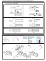
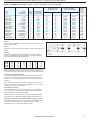
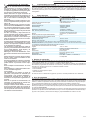
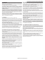
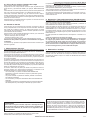
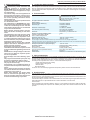
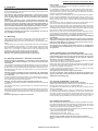
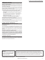
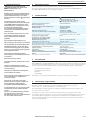
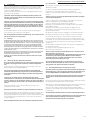
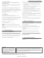
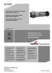
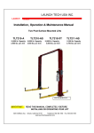
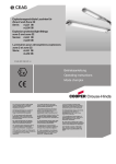
CROUSE-HINDS Instrucciones de uso Operating instructions Betriebsanleitung SERIES Luminarias para atmósferas explosivas Serie: AB 12 Explosion protected light fitttings Serie: AB 12 Explosionsgeschützte Leuchten Serie: AB 12 NOR 000000506982 (j) 08-06-2015 CZ: "Tento návod k použití si m žete vyžádat ve svém mate ském jazyce u p íslušného zastoupení spole nosti Cooper CrouseHinds/CEAG ve vaší zemi." H: "A kezelési útmutatót az adott ország nyelvén a Cooper Crouse-Hinds/CEAG cég helyi képviseletén igényelheti meg." P: "Se for necessária a tradução destas instruções de operação para outro idioma da União Europeia, pode solicita-la junto do seu representante Cooper Crouse-Hinds/CEAG" DK: "Montagevejledningen kan oversættes til andre EU-sprog og rekvireres hos Deres Cooper Crouse-Hinds/CEAG leverandør" I: "Se desiderate la traduzione del manuale operativo in un´altra lingua della Comunit à Europea potete richiederla al vostro rappresentante Cooper Crouse-Hinds/CEAG" PL: Niniejsz instrukcj obs ugi w odpowiedniej wersji j zykowej mo na zamówi w przedstawicielstwie firmy Cooper-CrouseHinds/CEAG na dany kraj. LT: Šios naudojimo instrukcijos, išverstos J su gimt j kalb , galite pareikalauti atsakingoje "Cooper Crouse-Hinds/CEAG" atstovyb je savo šalyje. S: "En översättning av denna montage- och skötselinstruktion till annat EU - språk kan vid behov beställas från Er Cooper CrouseHinds/CEAG- representant" LV: "Šo ekspluat cijas instrukciju valsts valod varat piepras t j su valsts atbild gaj Cooper Crouse-Hinds/CEAG p rst vniec b ." SK: "Tento návod na obsluhu Vám vo Vašom rodnom jazyku poskytne zastúpenie spolo nosti Cooper Crouse-Hinds/CEAG vo Vašej krajine." M: Jistg u jitolbu dan il-manwal fil-lingwa nazzjonali tag hom ming and ir-rappre entant ta' Cooper Crouse Hinds/CEAG f'pajji hom. SLO: "Navodila za uporabo v Vašem jeziku lahko zahtevate pri pristojnem zastopništvu podjetja Cooper Crouse-Hinds/CEAG v Vaši državi." E: "En caso necesario podrá solicitar de su representante Cooper Crouse-Hinds/CEAG estas instrucciones de servicio en otro idioma de la Union Europea" EST: "Seda kasutusjuhendit oma riigikeeles võite küsida oma riigis asuvast asjaomasest Cooper Crouse-Hindsi/CEAG esindusest." FIN: "Tarvittaessa tämän käyttöohjeen käännös on saatavissa toisella EU:n kielellä Teidän Cooper Crouse-Hinds/CEAG - edustajaltanne" GR: Hinds/CEAG" Cooper Crouse- NL: "Indien noodzakelijk kan de vertaling van deze gebruiksinstructie in een andere EU-taal worden opgevraagd bij Uw Cooper CrouseHinds/CEAG - vertegenwoordiging" RUS: "При необходимости, вы можете запрашивать перевод данного руководства на другом языке ЕС или на русском от вашего Cooper Crouse-Хиндс / CEAG - представителей." Luminarias para atmósferas explosivas Serie: AB 12 / Explosion protected light fitttings Serie: AB 12 / Explosionsgeschützte Leuchten Serie: AB 12 Fig. 1 Diagrama de conexión Serie AB 12 / Wiring diagram Serie AB 12 / Verdrahtungsplan Serie AB 12 Tipo / Type / Typ: C Tipo / Type / Typ: PL C Tipo / Type / Typ: E / EU / PLE Tipo / Type / Typ: LED LED 1E LED Fig. 2 Dimensiones / Dimensions / Abmessungen B M8 x 12 deep 144 140 A Tamaño envolvente Modo protección Enclosure size Protection mode GehäusegrößeSchutzart 1 Ex d IIC 2 Ex d IIB 3 Ex d IIB 4 Ex d IIB Dimensiones Dimensions Abmessungen [mm] AB 460 405 707 652 1.320 1.265 1.620 1.565 Fig. 3 EATON’S Crouse-Hinds Business 2/10 Luminarias para atmósferas explosivas Serie: AB 12 / Explosion protected light fitttings Serie: AB 12 / Explosionsgeschützte Leuchten Serie: AB 12 Tabla 1. Configuración de tipos / Table. 1 Types configuration / Typen Konfiguratiion Clase de temperatura Temperatura superficial Temperature class Surface temperature Temperaturklasse Umgebungstemperatur Tipo Tubos Tamaño Portalámparas Type Lamp Tubes Size Lampholder -20 +40ºC -20 +55ºC -20 +40ºC -20 +55ºC Typ Leuchtmittel Größe Lampenfassung AB12108* 1 x 8W 1 G5 T6 T5 T58ºC T73ºC AB12111PL* 1 x 11W 1 2G7 T6 T5 T58ºC T73ºC AB12118PL* 1 x 18W 1 2G11 T5 T5 T76ºC T91ºC AB12218PL* 2 x 18W 1 2G11 T5 T5 T76ºC T91ºC AB12124PL* 1 x 24W 1 2G11 T5 T5 T76ºC T91ºC AB12120* 1 x 18/20W(C) 2 G13 T5 T5 T78ºC T93ºC AB12220* 2 x 18/20W(C) 2 G13 T5 T5 T78ºC T93ºC AB12220LED* 2 x 600mm 2 G13 T6 T6 T85ºC T85ºC AB12236PL* 1 x 36W 2 2G11 T5 T5 T70ºC T85ºC AB12155PL* 1 x 55W 2 2G11 T5 T5 T70ºC T85ºC AB12140* 1 x 36/40W(C) 3 G13 T5 T5 T78ºC T93ºC AB12240* 2 x 36/40W(C) 3 G13 T5 T5 T78ºC T93ºC AB12240LED* 2 x 1200mm 3 G13 T6 T6 T85ºC T85ºC AB12165* 1 x 58/65W(C) 4 G13 T5 T5 T78ºC T93ºC AB12265* 2 x 58/65W(C) 4 G13 T5 T5 T78ºC T93ºC AB12265LED* 2 x 1500mm 4 G13 T6 T6 T85ºC T85ºC Tabla 2. Máximo número de luminarias con reactancia electrónica, por cada circuito protegido por MCB’S Peso Weight Gewicht [k] 3,90 4,00 4,40 4,80 4,40 6,75 7,15 6,35 7,15 6,75 8,60 9,00 8,20 10,20 10,60 9,80 Fig.4 Table. 2 Quantity Max. of lamps with electronic ballats, for each circuit protected by MCB’S Tabelle 2 Maximale empfohlene Anzahl angeschlossener Leuchten mit elektronischem Vorschaltgerät an einen Stromkreis, der mit einem einpoligen Leitungsschutzschalter (MCB) abgesichert ist. MCB1X18W 2x18W 1x36W 2x36W 1X58W 2X58W B10A23 15 16 10 16 7 C10A46 30 32 20 32 14 B16A52 34 35 20 33 13 C16A104 68 70 40 66 26 De ser necesario conectar más cantidad de lámparas por cada MCB, instalar un relé temporizado en el circuito, como se indica en Figura 4 con el fin de evitar que el pico de corriente al arranque ocurra simultáneamente. Protección contra defectos a tierra La corriente de defecto a tierra de las luminarias AB12 es normalmente inferior a 1 mA, por esta razón se recomienda no instalar más de 30 luminarias por cada interruptor de protección de tierras con sensibilidad de 30mA. If it is necessary connect more luminaries in each MCB, a timer device shoulbbe installed in the circuit, as well as indicated in Figure 4 in order to avoid the current peak at the same time. Earth leakage protection The earth leakage current of the luminaries AB12 is normally less than 1 mA, due to this it is suggested non install more than 30 luminaries for earth leakage switch with sensibility of 30mA. Werden mehrere Leuchten an einem Leitungsschutzschalter betrieben, sollten diese über ein Zeitrelais verzögert eingeschaltet werden (Fig. 4). Anschluss an Stromkreise mit einem FI Schutzschalter IA = 30mA Der Fehlerstrom der AB 12 Ni ist normal geringer 1 mA. Es sollten jedoch nicht mehr als 30 Leuchten an einen FI Schutzschalter mit einem Auslösestrom von IA = 30mA angeschlossen werden. EATON’S Crouse-Hinds Business 3/10 Luminarias para atmósferas explosivas Serie: AB 12 1. Instrucciones de seguridad La instalación y conexiones eléctricas de las luminarias deben ser realizadas por electricistas y/o personal cualificado e instruido de acuerdo con EN/IEC 60079-14 y la respectiva legislación nacional para aparatos eléctricos en atmósferas explosivas. Deben observarse las reglas nacionales de seguridad y de prevención de accidentes, así como las instrucciones de seguridad indicadas en este manual en itálica-negrita, como este texto. Estas luminarias no deben instalarse ni funcionar en emplazamientos peligrosos de Zonas 0 ó 20. Deben considerarse por el usuario los requisitos de la norma IEC/EN60079-31 en relación con excesivos depósitos de polvo y temperatura. Las temperaturas superficiales indicadas no se aplican con capas de polvo de más de 5mm de espesor. No abrir con tensión y dejar transcurrir al menos 10 minutos antes de abrir la luminaria para permitir un adecuado enfriamiento. Debe tenerse en cuenta la clase térmica y el grupo de explosión que aparece en la caratula de las luminarias. Se observará la temperatura ambiente de uso para garantizar el cumplimiento de la clase térmica o la temperatura superficial indicada en la caratula de la luminaria Las luminarias se harán funcionar según lo previsto y únicamente deben utilizarse cuando no existan defectos, estén limpias y en perfectas condiciones de uso. Mantenga la envolvente debidamente cerrada cuando la luminaria este en funcionamiento. Deben observarse los datos técnicos indicados en el punto 3 como así también los indicados en la luminaria. No están permitidos los cambios en el diseño ni las modificaciones en las luminarias que puedan afectar la protección contra explosión. Evitar múltiples funcionamientos de corta duración. Para reemplazos y reparaciones deben usarse solo recambios originales Crouse-Hinds. Las reparaciones que afecten al modo de protección, sólo pueden ser realizadas por Crouse-Hinds o por personal cualificado y seguidamente revisadas por un experto de acuerdo con los respectivos reglamentos nacionales. Antes de su puesta en funcionamiento, las luminarias se comprobarán de acuerdo con las instrucciones de la sección 6. Cualquier material extraño deberá ser retirado de las luminarias antes de su puesta en funcionamiento. No guardar estas instrucciones de operación en el interior de las luminarias durante su funcionamiento. 2. Conformidad con normas 3. Datos técnicos Estas luminarias para atmósferas explosivas están conformes a las normas indicadas en la declaración de conformidad CE. Han sido diseñadas, fabricadas y ensayadas según el estado del arte y de la técnica actual y de acuerdo con EN ISO 9001, así como a la Directiva 94/9/CE “Aparatos y sistemas de protección para su uso en atmósferas explosivas” y 2004/108/EC “Compatibilidad electromagnética”. Categoría de aplicación directiva ATEX 94/9/EG: Certificado de examen CE de tipo: Tensión nominal: Electromagnética (C) Electrónica (E): Electrónica universal (EU) LED, LED 1E (directa sin driver): Bornes: Grado de protección según EN/IEC 60529: Clase de aislamiento según EN/IEC 60598: Temperatura ambiente de uso: Electrónicas (E, EU) Otras (C, LED, LED 1E) II 2 G Ex d IIB T6…T5 Gb II 2 G Ex d IIC T6…T5 Gb II 2 D Ex tb IIIC T58…T93°C Db Véase tabla en la Fig. 2 y tabla 1 LOM 02ATEX2013X 220-230V, 50/60Hz 198-254V, 50/60Hz 175-280 VDC 110-260V, 0, 50/60Hz T8 hasta 277V, 0-50/60Hz Consultar al fabricante del tubo LED 2x2,5mm2 L y N, 6mm2 PE ext. IP 67 I -20ºC a + 40ºC -20ºC a + 55ºC Se reduce la Ta máxima a +40ºC debido al Tw de las reactancias electrónicas, a temperaturas superiores EATON Crouse-Hinds no puede garantizar la vida útil de las mismas. En el caso de uso de tubos LED, consultar con el fabricante la temperatura adecuada de trabajo de los mismos. Temperatura de almacenamiento en embalaje original: Material: Globo: Terminación: Color (versión estándar): Dimensiones: Entradas de cable: -40ºC a + 60ºC Aleación de aluminio exento de Cu Vidrio Borosilicato Pintura epoxi RAL 7032, tapa RAL 7016 Véase Fig. 2 2x3/4”NPT ó 2xM25x1,5 ó 2xM20x1,5, una taponada 4. Ámbito de aplicación Estas Luminarias, están diseñadas para su uso en atmósferas potencialmente explosivas, Zonas 1 y 2 según EN/IEC 60079-10-1 y en zonas 21 y 22 según EN/IEC 60079-10-2. Los materiales de la envolvente utilizada, incluidas las partes metálicas externas, son materiales de alta calidad que garantizan la resistencia a la corrosión y resistencia a las sustancias químicas de acuerdo a los requisitos para uso en un ambiente industrial “normal”. - Aluminio exento de cobre. - Acero inoxidable. - Acabado con pintura epoxi en polvo. - Vidrio borosilicato En caso de uso en un ambiente muy agresivo, por favor, consulte previamente con el fabricante. 5. Uso / Propiedades Las luminarias pueden ser usadas en interior o exterior para iluminar áreas peligrosas por atmósferas potencialmente explosivas de gas o polvo, se pueden utilizar sólo en lugares con bajo riesgo impacto mecánico, debido a la operación normal en el proceso industrial. La clase térmica, el grupo de explosión y la temperatura ambiente de uso pueden encontrase en las tablas y datos técnicos. Se deberán tener en cuenta los datos indicados en las secciones 2 y 4 durante el uso. No está permitida ninguna aplicación o uso fuera de la aquí descripta sin una declaración de consentimiento escrita por parte de Crouse-Hinds. Se observarán las instrucciones estipuladas en la sección 7 de estas instrucciones de uso durante la operación. El operador/usuario debe determinar bajo su única responsabilidad la idoneidad del equipo para su uso previsto y asume todos los riesgos y responsabilidades en relación con ello. EATON’S Crouse-Hinds Business 4/10 Luminarias para atmósferas explosivas Serie: AB 12 6. Instalación La instalación y operación deben ser realizadas de acuerdo con EN/IEC 60079-14, la normativa nacional pertinente y las normas generalmente reconocidas de la ingeniería. El transporte y almacenamiento de estas luminarias sólo está permitido en su embalaje original y en las posiciones especificadas. Tener especial cuidado cuando se instalan, mantienen o reparan las luminarias de no dañar la piel exterior del vidrio, ya sea por pequeños golpes, abrasión, arenado, etc. ya que esto puede debilitar sus propiedades mecánicas. La radiación solar directa e intensa en áreas de alta temperatura ambiente puede producir una temperatura inadmisiblemente elevada en el interior de las luminarias. Esto puede resultar en una reducción drástica de la vida útil de los componentes electrónicos interiores. Por lo tanto las luminarias deben estar apagadas durante el día por un control de la fotocélula por ejemplo. Debe tenerse en cuenta el máximo número de luminarias con reactancia electrónica conectadas en un mismo circuito, como se indica en la tabla 2. Una instalación u operación inadecuada de las luminarias pueden dar lugar a la invalidación de la garantía. 6.1 Montaje Las distancias de fijación se muestran en la figura 2 (B). Estas luminarias son aptas para montaje techo, mural o en báculo, los accesorios de montaje no se incluyen en el suministro, véase el catálogo Crouse-Hinds para una correcta selección de los accesorios de montaje. Las instrucciones de uso para los diferentes accesorios de montaje se suministran con estos. Véase los planos y/o instrucciones de montaje específicas para cada accesorio de montaje. Las luminarias deberán fijarse de manera uniforme, planas, libres de torsión y sólo en los puntos de fijación previstos para ello. Los tornillos, no incluidos en el suministro, que se elijan deberán ajustarse al orificio de fijación y no dañar el mismo (por ejemplo mediante el uso de una arandela plana). El número de tornillos utilizados para fijar las luminarias se corresponderá con el número de agujeros de fijación. Se prestará especial atención a las conexiones de puesta a tierra. Advertencia: Si se aprieta demasiado puede dañarla luminaria. 6.2 Apertura de la luminaria / Conexión eléctrica Antes de abrir la luminaria, es necesario asegurarse de que no hay tensión y que se han dejado enfriar pos al menos 10 minutos después de la desconexión. La conexión de las luminarias sólo puede llevarse a cabo por los especialistas. Las luminarias deben conectarse directamente dentro de las envolventes antideflagrante utilizando para ello entradas de cables debidamente certificadas en modo de protección antideflagrante Ex-d, por lo que se tomarán en cuenta las instrucciones de montaje indicadas para dichas la entradas del cable (véase la sección 6.3 entradas de cables). Advertencia: A fin de mantener el modo de protección Ex-d, es esencial prestar atención al correcto montaje del cable y de las entradas de cables. Para abrir la envolvente antideflagrante (véase la Fig. 3), se tiene que desenroscar el tornillo de enclavamiento (1) en la tapa, ahora se puede quitar la tapa (2) girando la misma en sentido anti-horario. Advertencia: Si bien la tapa posee un mecanismo de seguridad, deberá protegerse esta contra una caída o golpes. Para mantener la protección contra explosiones, los conductores se conectarán con especial cuidado. El aislamiento del cable debe llegar hasta el borne de conexión. El cable en si mismo no estará dañado. Se deberá respetar las secciones de cable máximas y mínimas que se especifican en el punto 3 para los bornes de conexión. Todos los tornillos y las tuercas de los terminales o bornes de conexión, incluidos los que no estén en uso, deberán apretarse correctamente y de forma segura. Un apriete excesivo puede afectar a la conexión. 6.2.1 Lámparas Los tubos apropiados para cada tipo de luminaria están especificados en la tabla 1 como así también en la carátula de las luminarias. Para la instalación de los tubos, una vez realizados los pasos del punto 6.2 (véase Fig. 3), quite las dos tuercas (4) y extraiga la bandeja (5). Tener especial cuidado al retirar el cable para la conexión a tierra interna entre la bandeja y el cuerpo de la luminaria. Instale o reemplace los tubos apropiados en los respectivos portalámparas, controle que estén instalados con seguridad, inserte nuevamente la bandeja, véase Fig. 3 (5), conecte el cable para la conexión a tierra interna entre la bandeja y el cuerpo de la luminaria, enrosque las dos tuercas (4), y luego cierre la luminaria tal y como se indica en el punto 6.4. Sólo pueden utilizarse los tubos aprobados para cada tipo de luminaria, si se tiene cualquier duda acerca de los tubos a utilizar, por favor consulte con Crouse-Hinds. Debido a que pueden usarse tubos LED de diferentes fabricantes, se ha de tener en cuenta la correcta selección de los tubos de LED para las luminarias tipo LED. Estos deben ser adecuados para la conexión directa a la red, sin ningún tipo de equipo de encendido ni reactancia, han de ser tubos LED T8 para casquillo G13 y de la longitud adecuada. Antes de instalar los tubos LED, verificar que son adecuados para el cableado indicado en el interior de la luminaria y en la Fig. 1 para los tipos “LED” y “LED 1E”. Advertencia: No instale ningún tipo de tubos fluorescentes en las luminarias tipo LED. Debido a que este tipo de luminarias LED tienen conexión directa a la red y no tienen equipo de control en el interior que limite la corriente, el uso de tubos fluorescentes en este tipo de luminarias LED pueden causar un cortocircuito interno, o una explosión que puede destruir la luminaria. El uso indebido de las luminarias tipo LED puede dar lugar a la invalidación de la garantía. 6.3 Entradas de cable Ex-d / Tapones Ex-d Sólo pueden usarse entradas de cable y tapones debidamente certificados Ex-d. Estos deben ser aptos para el mismo grupo de explosión que las envolventes, en este caso, grupo IIC o IIB para gases (véase tabla en Fig.2) y grupo IIIC para polvo. Deben observarse las directrices pertinentes de montaje e instalación del fabricante para las entradas de cables y los tapones antideflagrantes Ex-d certificados. Al utilizar las entradas de cables con un grado de protección IP inferior al grado de protección IP de las envolventes de los equipos (véase el punto 3, datos técnicos), el grado de protección IP para la unidad completa se reduce. Con el fin de asegurar el grado de protección IP mínimo requerido, las entradas de cable deberán estar correctamente apretadas. Un apriete excesivo puede deteriorar el grado de protección. Con el fin de garantizar y/o establecer la protección contra explosiones y el grado de protección, las entradas no utilizadas se obturarán con tapones debidamente certificados Ex-d. EATON’S Crouse-Hinds Business 5/10 6.4 Cierre de los equipos / bloqueo de la tapa Retire cualquier elemento extraño del equipo. Engrase la rosca de la tapa antes de colocar la tapa, de preferencia con grasa térmica y químicamente estable, por ejemplo: MOLIKOTE® BR2 plus. Preste atención al correcto alojamiento de las juntas de estanqueidad en la tapa, Las juntas han de estar limpias y no presentaran daño alguno. Para cerrar la luminaria, véase Fig. 3 (2), es necesario colocar la tapa en la base correctamente (si es necesario, gire la tapa en sentido antihorario). La cubierta puede ahora enroscarse a la base girándola en sentido horario hasta que se alcance el tope. Después de esto, la cubierta se fijará en la posición con el tornillo de enclavamiento de la tapa, véase Fig. 1 (3). 6.5 Puesta en marcha Antes de poner en funcionamiento las luminarias, se llevarán a cabo los ensayos especificados en las respectivas normas nacionales. Además de esto, antes de su puesta en marcha, se verificará de acuerdo con estas instrucciones de funcionamiento y demás normativa aplicable el correcto funcionamiento de las luminarias. Sólo se llevarán a cabo medidas de aislamiento entre PE y los conductores externos L1 (L2, L3), así como entre PE y N. - Tensión de ensayo: Max. 1KV CA/CC - Corriente de ensayo: Máx. 10 mA La luminaria sólo puede utilizarse cuando está debidamente cerrada. Advertencia: Sólo pueden ser puestos en funcionamiento los equipos certificados. La instalación y/u operación inapropiada de las luminarias conlleva la pérdida de su garantía. 7. Mantenimiento / Servicio Deben observarse las regulaciones nacionales pertinentes que se aplican para el mantenimiento / servicio de aparatos eléctricos en atmósferas explosivas, por ejemplo EN/IEC 60079-17. Antes de abrir las envolventes, es necesario asegurarse que la tensión de alimentación de los equipos haya sido debidamente desconectada y que se ha dejado transcurrir el tiempo entre desconexión y apertura especificado en las envolventes. El intervalo necesario entre mantenimientos depende de la aplicación específica y será estipulado por el usuario de acuerdo a las respectivas condiciones de operación. Se recomienda un mantenimiento regular de acuerdo a un programa aprobado de mantenimiento preventivo. Como parte de las rutinas de pruebas los dispositivos de disparo por protección diferencial deben ser probados dos veces al año. En servicio, sobre todo, las partes que afectan a la protección contra explosiones, tendrán que inspeccionarse visualmente y controlarse con la finalidad de asegurar su correcto estado, por ejemplo: - Las envolventes y sus partes roscadas estarán debidamente engrasadas, en buenas condiciones, limpias no presentaran grietas, daños ni corrosión. - Las juntas roscadas no pueden ser tratadas, pintadas ni barnizadas, sólo estarán engrasadas. - Las conexiones y los tapones obturadores deben estar debidamente apretados. - Comprobar la eficiencia e integridad de todas las juntas de estanquei- dad. Reemplace las juntas antiguas o dañadas por juntas nuevas. ADVERTENCIA Para evitar el riesgo de incendio, explosión o descarga eléctrica, este producto debe ser instalado, inspeccionado y mantenido por un electricista cualificado, de acuerdo con los reglamentos eléctricos aplicables. Luminarias para atmósferas explosivas Serie: AB 12 Las piezas dañadas se sustituirán inmediatamente por piezas de recambio originales o serán reparadas por el fabricante. Compruebe que las conexiones, las entradas de cables y tapones ciegos estén apretados debidamente y de forma segura. Todo el material eléctrico y electrónico en el interior de las envolventes se mantendrá de acuerdo a sus propias instrucciones. Si, durante las operaciones de mantenimiento, se comprueba que es necesario efectuar reparaciones, deberá observarse la sección 8 de estas instrucciones de uso. 8. Reparación / Reacondicionamiento / Modificaciones Las reparaciones y reacondicionamientos sólo pueden llevarse a cabo con piezas de recambios genuinas Crouse-Hinds. Aísle y quite tensión antes de abrir cualquier envolvente y comenzar el desmantelamiento de cualquier pieza individual. Utilice sólo piezas de repuesto originales. Las reparaciones que afecten al modo de protección contra explosiones sólo pueden llevarse a cabo por Crouse-Hinds o por un electricista cualificado de acuerdo con la respectiva reglamentación nacional. Para las reparaciones de equipos con modo de protección es aconsejable seguir las pautas establecidas en la norma EN/IEC 60079-19. No están permitidas las modificaciones en el dispositivo ni cambios en su diseño. ¡Todas las reparaciones se harán sin tensión! En caso de daño en las envolventes antideflagrantes u otra parte de los equipos que pudiera afectar al modo de protección, es obligatoria la sustitución de dichas partes. En caso de duda, los respectivos equipos se enviarán a Crouse-Hinds para su reparación. Sólo es posible la reconstrucción o modificación de los equipos dentro del alcance de las homologaciones y serán certificadas después. 9. Eliminación / reciclaje Cuando el equipo o cualquiera de sus partes se elimina, deberán observarse los respectivos reglamentos nacionales en materia de eliminación de residuos. Con el fin de facilitar el reciclaje de los distintos componentes, las piezas de plástico incluyen una marca de identificación del material plástico utilizado. Todas las declaraciones, información técnica y recomendaciones contenidas en este documento están basadas en la información y las pruebas que consideramos fiables. La exactitud o la exhaustividad de los mismos no están garantizados. De acuerdo con los “Términos y Condiciones de Venta” de Crouse-Hinds, y dado que las condiciones de uso están fuera de nuestro control, el comprador debe determinar la idoneidad del producto para su uso previsto y asume todos los riesgos y responsabilidades en relación con ello. Sujeto a cambios y/o suplementos de esta serie sin previo aviso. Guarde estas instrucciones para futuras referencias. EATON’S Crouse-Hinds Business 6/10 Explosion protected light fitttings Serie: AB 12 1. Safety Instructions This product should be Installed and connected by skilled electricians and instructed personnel in accordance with IEC/EN 60079-14 and the respective national legislation on electrical equipment for explosive atmospheres. The national safety rules and regulations for the prevention of accidents, as well as the safety instructions, like this text set in bold-italics in these operating instructions manual, shall be observed! The luminaries must not be operated in Zone 0 or 20 hazardous areas. The requirements of IEC/EN60079-31 regarding excessive dust deposits and temperature must be considered by the user. The indicated surface temperatures are not related to a layer above 5mm thickness Before opening, electrical power to the luminaire must be turn off during at least 10minutes! The temperature class and explosion group stated on the luminaire shall be observed. To ensure adherence to the temperature class or surface temperature stated on the type label of the luminaire, the permissible ambient temperature shall be observed. Light fitting shall be used for their intended purpose and shall be undamaged and in a perfect and clean conditions. Keep tightly closed when in operation. The technical data indicated in point 3 as well as those indicated in light fitting, must be observed. Modifications or design changes to this luminaries that can affect the explosion protection are not permitted. Avoid multiple, short time switching operation Only original Crouse-Hinds spare parts may be used as replacements and for repairs. Repairs that affect the explosion protection may only be carried out by Crouse-Hinds or by a qualified electrician in compliance with the respective national regulations. Prior to being put into operation, the luminaries shall be checked in accordance with the instructions as per section 6. Before initial operation, any foreign matter shall be removed from light fitting, do not keep this operating instructions manual inside of the luminaire during its operation. 2. Conformity with standards This light fitting is conform to the standards specified in the EC-Declaration of conformity. It has been designed, manufactured and tested according to the state of the art and to DIN EN ISO 9001, 94/9 EC: Equipment and protective systems intended for use in potentially explosive atmospheres. The light fitting fulfill further requirements, such as the EC directive on electromagnetic compatibility (2004/108/EC). 3. Technical data Apparatus marking acc. to 94/9/EG and directive: EC-type examination certificate: Rated voltage: Electromagnetic ballast (C) Electronic (E): Electronic universal (EU) LED, LED 1E (direct w/o driver): Terminals: Degree of protection EN/IEC 60529: Insulation class EN/IEC 60598: Perm. ambient temperature: Electronic types (E, EU) Other types (C, LED, LED 1E) II 2 G Ex d IIB T6…T5 Gb II 2 G Ex d IIC T6…T5 Gb II 2 D Ex tb IIIC T58…T93°C Db See table in Fig. 2 and table 1 LOM 02ATEX2013X 220-230V, 50/60Hz 198-254V, 50/60Hz 175-280 VDC 110-260V, 0, 50/60Hz T8 up to 277V, 0-50/60Hz Ask LED tube manufacturer 2x2,5mm2 L y N, 6mm2 PE ext. IP 67 I -20ºC to + 40ºC (E or EU) -20ºC to + 55ºC The Ta range for electronic ballast is reduced up to +40ºC due to their Tw, at higher temperature EATON Crouse-Hinds cannot guarantee their normal life. When LED tubes are used, the manufactures shall be consulted for their maximum operating temperature. Storage temperature in original packaging: Enclosure material: Glass material: Enclosure surface finish: Color of enclosure (standard version): Dimensions: Cable entries: -40ºC to + 60ºC Aluminium alloy casting (Cu free) Borosilicate glass Plastic powder coating RAL 7032, cover RAL 7016 See Fig. 2 2xM25x1,5 or 2x3/4”NPT one with blanking plug 4. Field of application This light fitting is intended for use in potentially explosive atmospheres in zones 1, 2 and 21, 22 in accordance with EN/IEC 60079-10. The enclosure materials used, including any external metal parts, are high quality materials that ensure a corrosion resistance and resistance to chemical substances according to the requirements for use in a ”normal industrial atmosphere”: - Copper free aluminium alloy casting - Plastic powder coating finish - Stainless steel -Borosilicate glass In case of use in an extremely aggressive atmosphere, please consult to the manufacturer. 5. Use/Properties This light fitting can be use inside or outside to illuminate areas with potentially explosive atmospheres, may be used only in places with low mechanical impact risk, due to the normal operation in the industrial process. The temperature class, explosion group and permissible ambient temperature can be found in the tables and technical data. The data according to sections 2 and 4 shall be taken into account during use. Applications other than those described are not permissible without a written declaration of consent from Crouse-Hinds. During operation the instructions stated in section 7 of the operating instructions shall be observed. The sole responsibility with respect to the suitability and proper use of these luminaries lies with the operator. EATON’S Crouse-Hinds Business 7/10 Explosion protected light fitttings Serie: AB 12 6.2.1 Lamp 6. Installation The EN 60079-14, relevant national regulations and the generally recognized rules of engineering shall be applied for the installation and operation. Transport and storage of the luminaries is permitted in the original packaging and specified positions only. Pay attention when installing, maintaining or repairing the light fittings, do not damage the fire-finish of the glass surface by abrasions, sanding, small strokes, etc. that can weaken their mechanical functions. Intensive sun radiation in areas of high ambient temperatures may cause inadmissible temperature rise inside of the luminaries. This may result a decrease in lifetime of the electronic ballast (EVG) or electronic components inside of the luminaries. Therefore those luminaries should be switched off during daytime by a photocell control. The maximum number of luminaries with electronic ballast connected to the same circuit as indicated in the table 2 should be observed The improper installation and operation of light fittings can result in the invalidation of the guarantee. 6.1 Mounting Fixing dimensions are shown in Figure 2 (B). Luminaries are suitable for ceiling, wall or pole mounting, the accessories are not included, see Crouse-Hinds catalogue for the correct selection of the mounting accessories. The light fitting may only lie flat on and be fixed torsion-free to the fastening points provided for direct assembly. The screws chosen shall fit the fixing hole and shall not damage the hole (e.g. use of a washer, select the correct length, etc.). The number of screws used for fixing the equipment shall correspond to the number of fixing holes in the light fitting. Special attention shall be paid to the PE connections. Warning: Over tightening might damage the light fitting. 6.2 Opening the device / Electrical connection Before opening the light fitting, it is necessary to ensure that there is no voltage and it must be allowed to cool down for 10 minutes after switching off. The connection of explosion-protected light fittings may only be carried out by specialists. These luminaries shall be connected directly in the flameproof enclosure using certified flameproof cable entries, whereby the mounting instructions for the cable entry shall be taken into account (see Section 6.3 Cable Entries). Warning: In order to establish the type of protection “Ex-d flameproof “, it is essential to pay attention to the correct mounting of the cable and cable entry. To open a flameproof enclosure (see Fig. 3), the interlocking screw, item 1, in the cover has to be unscrewed. The cover, item 2, can then be removed from the luminary by turning it anticlockwise. Warning: The cover shall be safeguarded against falling off. To maintain the explosion protection, conductors shall be connected with special care. The insulation shall reach up to the terminal. The conductor itself shall not be damaged. The minimum and maximum conductor cross sections that can be connected shall be observed, see point 3 technical data. All screws and/or nuts of connection terminals, including those not in uses, shall be tightened down securely. Excessive tightening can affect the connection. The lamp tube type approved for each light fitting is specified in table 1 and in the label of the luminaries. For installation of lamps tubes, once performed the steps mentioned in point 6.2 (see Fig 3), remove the 2 nuts item 4 and extract the tray, item 5. Take special care to remove correctly the cable for internal PE connection between tray and body of the light fitting. Install or replace the suitable lamps into the corresponding lamp holders, test for a secure installation, insert the tray again, see Fig. 3 item 5, connect the cable for internal PE connection between tray and body of the light fitting, screw the 2 nuts, item 4, and then close the light fitting as indicated in point 6.4. Only lamps tubes that are approved for each type of light fitting may be used. If you have any doubt, please consult with Crouse-Hinds. Due you can use LED tubes from many manufacturers, observe the correct selection of LED tubes according to the light fittings LED type, these must be suitable for direct mains connection without any driver, ballast or control gear, T8 for G13 lamp socket and with appropriate length. Special care to control the correct LED tubes selection according to the luminaire wiring type shall be taken. Wiring type is showed in the internal tray of the luminaire and in the Fig. 1 for the types LED and LED 1E. Warning: Do not install any type of fluorescent lamps in any LED type light fittings. Due to these LED type of light fittings have direct mains connection and have no control gear inside, the use of fluorescent tubes in these LED type of light fittings can cause an internal short circuit or an explosion that can destroy the light fitting. The improper use of LED type luminaires and the use of LED tubes not suitable for the provided wiring may result in an invalidation of the guarantee. 6.3 Ex-d cable entries / Ex-d blanking plugs Only suitable certified flameproof cable entries and certified flameproof blanking plugs may be used. These should be for the same groups of explosion of the light fittings, in this case IIC or IIB (see table in Fig. 2) for gas and IIIC for dust. The relevant mounting and installing manufacturer directives for certified cables entries and blanking plugs shall be observed. When using cable entries with a degree of protection that is lower than the IP protection of the light fitting (see Technical Data), the degree of protection IP for the complete unit is reduced. In order to ensure the required minimum degree of protection, the cable entries shall be tightened down securely. Over tightening can impair the degree of protection. In order to guarantee and/or establish the explosion protection and degree of protection, unused entry holes shall be sealed with a certified flameproof blanking plug. 6.4 Closing equipments / Cover lock Any foreign matter shall be removed from the equipment. Grease the cover thread before screwing the cover, preferably with grease thermally and chemically stable i.e.: Molikote® BR2 plus. Pay attention to the correct fit of the seal into the cover. All seals must be clean an undamaged To close the light fitting, see fig. 3 item 2, it is necessary to fit the cover onto the light fitting body correctly (if necessary, turn the cover anticlockwise). The cover can then be screwed into the enclosure base by turning it in a clockwise direction until the stop is reached. After this, the cover shall be fixed in position with the interlocking screw of the cover, see Fig. 3 item 1. 6.5 Putting into operation Before putting the light fitting into operation, the tests specified in the individual national regulations shall be performed. In addition to this, the correct functioning of the light fitting shall be checked in accordance with these operating instructions and other applicable regulations. Only carry out insulation measurement between PE and external conductor L1 (L2, L3) as well as between PE and N. - Measurement voltage: Max. 1KV AC/DC - Measurement current: Max. 10 mA The light fitting may only be operated when closed Warning: Only certified equipments may be put into operation. Improper installation and operation of the lamp leads to loose of the guarantee. EATON’S Crouse-Hinds Business 8/10 Explosion protected light fitttings Serie: AB 12 7 Maintenance / Servicing The valid national regulations for the maintenance/servicing of electrical equipments for use in potentially explosive atmospheres shall be observed (i.e. EN/IEC 60079-17). Before opening the enclosure, it is necessary to ensure that the voltage supply has been isolated and should allowed to cool down for 10 minutes after switching off. The necessary intervals between servicing depend upon the specific application and shall be stipulated by the operator according to the respective operating conditions. We recommend a regular maintenance according to an approved preventive maintenance program. During servicing, above all, parts on which the explosion protection depends shall be tested or visually inspected to ensure their correct state, i.e.: - Enclosure threaded parts like cover and cable entries, shall be properly greased, in good conditions, clean and without any corrosion or damaged. - The thread shall not be treated, painted nor varnished!, preferably with grease thermally and chemically stable i.e.: Molikote® BR2 plus. - Check all seals for efficiency and intactness. Replace older or damaged seals with new seals. - Be aware about the lamp tube change intervals specified by the manufacturer of it, lamp tubes types must be as specified. Any damaged parts shall be replaced immediately using original parts or damaged parts shall be repaired by the manufacturer. Check that connection terminals, cable entries and blind plugs fit securely. All electrical and electronic material inside of the enclosure shall be maintained as per their own instructions. If, in the course of servicing, it is ascertained, that repairs are necessary, section 8 of these operating instructions shall be observed. 8 Repair / Overhaul / Modifications Repairs and overhaul may only be carried out with genuine Crouse-Hinds spare parts. Switch off the equipment before opening or isolate it before the dismantling of individual parts. Only use original spare parts. Repairs that affect the explosion protection may only be carried out by Crouse-Hinds or a qualified electrician in compliance with the applicable national rules. For repair electrical equipments in protection mode is suggested follow the instructions indicated in EN/IEC 60079-19. Modifications to the equipments or changes of its design are not permitted. All reparations have to be done without voltage! In the event of damage to the flameproof enclosures or other part of equipments that could affect the mode of protection, replacement of these components is mandatory. In case of doubt, the respective equipments shall be sent to Crouse-Hinds for repair. Reconstruction or modifications to equipments are only possible within the scope of the approvals and shall be certified afterwards. 9 Disposal / Recycling When the equipment or their parts is disposed of, the respective valid national regulations on waste disposal shall be observed. In order to facilitate the recycling of individual components, plastic parts are provided with the identification mark of the plastic material used. Warning To avoid the risk of fire, explosion, or electric shock, this product should be installed, inspected, and maintained by a qualified electrician only, in accordance with all applicable electrical codes. All statements, technical information and recommendations contained herein are based on information and tests we believe to be reliable. The accuracy or completeness thereof are not guaranteed. In accordance with Crouse-Hinds “Terms and Conditions of Sale” and since conditions of use are outside our control, the purchaser should determine the suitability of the product for his intended use and assumes all risk and liability whatsoever in connection therewith. Subject to alteration or supplement of this product without any advertisement before. Save these instructions for future reference. EATON’S Crouse-Hinds Business 9/10 Explosionsgeschützte Leuchte Serie: AB 12 1. Sicherheitshinweise 2.Normenkonformität Zielgruppe dieser Anleitung sind Elektrofachkräfte und unterwiesene Personen in Anlehnung an die EN/IEC 60079-14. Die Leuchte entspricht den aufgeführten Normen in der Konformitätserklärung. Beachten Sie die nationalen Unfallverhütungsund Sicherheitsvorschriften und die nachfolgenden Sicherheitshinweise, die in dieser Betriebsanleitung mit einem ( ) gekennzeichnet sind! Die Leuchte darf nicht in den Zonen 0 und 20 eingesetzt werden! Die Anforderungen an die EN/IEC 60079-31 bezüglich zu hoher Staubablagerungen und Temperatur müssen vom Anwender beachtet werden. Die angegebenen Oberflächentemperaturen sind nicht auf eine Schichtdicke über 5mm Stärke bezogen. Bevor die Leuchte geöffnet wird, muss diese spannungsfrei geschaltet werden und ausgeschaltet mindestens 10 Minuten abgekühlt. Die angegebene Temperaturklasse und Explosionsgruppe der Leuchte ist zu beachten. Um die Einhaltung der Temperaturklasse bzw. Oberflächentemperatur, die auf dem Typenschild der Leuchte angegeben ist, zu gewährleisten, muss die zulässige Umgebungstemperatur eingehalten werden. Die Leuchte ist bestimmungsgemäß in unbeschädigtem und einwandfreiem Zustand zu betreiben! Die Leuchte wurde entsprechend dem Stand der Technik und gemäß DIN EN ISO 9001:2008 und EN ISO/IEC 80079-34:2011 entwickelt, gefertigt und geprüft. 3. Technische Daten Kennzeichnung nach 94/9/ EG: EG-Baumusterprüfbescheinigung: Bemessungsspannung: Elektromagnetische Vorschaltgeräte (C) Elektronisch (E): Elektronisch Universal (EU) LED, LED 1E (direkt, ohne Vorschalatgerät): Klemmvermögen Anschlussklemme: Schutzart nach EN/IEC 60529: Schutzklasse nach EN/IEC 60598: Zulässige Umgebungstemperatur: Elektronischer Typ (E, EU) Andere Typen (C, LED, LED 1E) II 2 G Ex d IIB T6…T5 Gb II 2 G Ex d IIC T6…T5 Gb II 2 D Ex tb IIIC T58…T93°C Db Siehe Tabelle in Bild 2 und Tabelle 1 LOM 02ATEX2013X 220-230V, 50/60Hz 198-254V, 50/60Hz 175-280 VDC 110-260V, 0, 50/60Hz T8 bis 277V, 0-50/60Hz Fragen Sie den Hersteller der LED-Röhren L = 2x2,5mm²; N = 6mm²; PE = extern. IP 67 I -20ºC bis + 40ºC (E oder EU) -20ºC bis + 55ºC Der Ta Bereich für elektronische Vorschaltgerät ist reduziert auf + 40 ° C aufgrund ihrer Tw bei höherer Temperatur. EATON Crouse-Hinds kann deren normale Lebendauer nicht garantieren. Werden LED-Röhren verwendet, muss die maximale Betriebstemperatur beim Hersteller erfragt werden. Lagertemperatur in Originalverpackung: Gehäusematerial: Glasmaterial: Gehäuse Ausführung: Farbe des Gehäuses (Standardausführung): Größe: Ex e-Kabel- und Leitungseinführung: -40ºC bis + 60ºC Leichtmetallguss (Cu frei) Borosilikatglas Kunststoffpulverbeschichtung RAL 7032, Verschlussdeckel RAL 7016 siehe Bild 2 2xM25x1,5 oder 2x3/4”NPT mit einem Blindstopfen Nicht unter Spannung öffnen! 4.Einsatzbereich Die technischen Daten gemäß Punkt 3 sind zu beachten. Diese Leuchte ist für den Einsatz in explosionsgefährdeten Bereichen der Zonen 1, 2 und 21, 22 nach EN/IEC 60079-10-1 und EN/IEC 60079-10-2 gedacht. Die eingesetzten Gehäusematerialien einschließlich der außenliegenden Metallteile bestehen aus hochwertigen Werkstoffen, die einen anwendungsgerechten Korrosionsschutz und Chemikalienresistenz in “normaler Industrieatmosphäre” gewährleisten: Umbauten oder Änderungen an dieser Leuchte, die den Explosionsschutz betreffen , sind nicht zulässig. Vermeiden Sie mehrfaches kurzzeitiges Einund Ausschalten der Leuchte. ls Ersatz dürfen nur Originalteile von Eaton’s A Crouse-Hinds Business / CEAG (Eaton) verwendet werden! Reparaturen, die den Explosionsschutz betreffen, dürfen nur von Eaton/CEAG oder einer qualifizierten „Elektrofachkraft“ durchgeführt werden (EN/IEC 60079-14)! Vor Inbetriebnahme muss die Leuchte gemäß den Anweisungen unter Punkt 6 überprüft werden. Lassen Sie diese Betriebsanleitung während des Betriebes nicht in der Leuchte. Alle Fremdkörper müssen vor Inbetriebnahme aus der Leuchte entfernt werden. - kupferfreie Aluminiumlegierung - Kunststoffpulverbeschichtung - Edelstahl - Borosilikatglas Beim Einsatz in extrem aggressiver Atmosphäre, wenden Sie sich bitte an den Hersteller. 5. Verwendung / Eigenschaften Diese Leuchte ist für den Einsatz innerhalb oder außenhalb von Gebäuden, in explosionsgefährdeten Bereichen, an Orten mit geringer mechanischen Gefährdung, zum Beleuchten geeignet. Sie kann auch im „normalen Industriebereich” verwendet werden. Die Temperaturklasse, Explosionsgruppe und zulässige Umgebungstemperatur ist den Tabellen und technischen Daten zu entnehmen. Die Angaben aus Punkt 2 und 4 sollen während der Verwendung berücksichtigt werden. Andere Anwendungen, als die beschriebenen, sind ohne schriftliche Einverständniserklärung von Crouse-Hinds nicht zulässig. Während des Betriebs sind die Hinweise des Kapitels 7 dieser Betriebsanleitung zu beachten. Die alleinige Verantwortung in Bezug auf die Eignung und die korrekte Verwendung dieser Leuchte liegt beim Betreiber. EATON’S Crouse-Hinds Business 10/10 Explosionsgeschützte Leuchte Serie: AB 12 6.Installation 6.2.1Leuchmittel Halten Sie die für das Errichten und Betreiben von explosionsgeschützten, elektrischen Betriebsmitteln geltenden Sicherheitsvorschriften und das Gerätesicherheitsgesetzes sowie die allgemein anerkannten Regeln der Technik ein! (EN/IEC 60079-14) Transport und Lagerung der Leuchte ist nur in der Originalverpackung und angegebener Lage gestattet! Das geeignete und zugelassene Leuchtmittel für jede Leuchte ist in der Tabelle 1 beschrieben. Vermeiden Sie Beschädigungen der Glasbeschichtung während der Montage oder Reparatur! Abrieb oder Sandstrahlen kann die mechanische Festigkeit aufheben! Intensive Sonneneinstrahlung in Regionen mit hohen Umgebungstemperaturen kann im Leuchteninneren zu unzulässig hohen Erwärmungen führen. Eine Reduzierung der Lebensdauer des EVGs und der elektronischen Bauteile, kann eine Folge hiervon sein. Zur Vermeidung sollte in diesen Regionen tagsüber die Leuchte über einen Lichtsensor geschaltet werden. Die maximale Anzahl an Leuchten mit elektronischem Vorschaltgerät in einem Stromkreis, ist zu beachten: Siehe Tabelle 2 Die unsachgemäße Installation und Bedienung der Leuchte kann den Verlust der Garantie zur Folge haben. 6.1Montage Die Befestigungsmaße sind in Bild 2 (B) gezeigt. Die Leuchte eignet sich für Decke, Wand oder Mastmontage. Zubehör ist nicht enthalten. Für die richtige Auswahl des Montagezubehörs, siehe Crouse-Hinds Katalog. Die Leuchte darf bei der Direktmontage nur an den vorgesehenen Befestigungspunkten, eben aufliegend und verwindungsfrei befestigt werden. Die verwendeten Schrauben müssen geeignet sein und dürfen die Halterungen nicht beschädigen (z.B. Unterlegscheiben verwenden, Schraubenlänge beachten, usw.). Die Anzahl der Schrauben zur Befestigung der Leuchte muss der Anzahl der Befestigungsbohrungen in der Leuchte entsprechen. Besonderes Augenmerk ist auf die PE-Anschlüsse zu legen. Achtung: Ein zu festes Anziehen der Schrauben kann die Leuchte beschädigen. 6.2 Öffnen des Gerätes / Elektrischer Anschluss Bevor die Leuchte geöffnet wird, muss diese spannungsfrei geschaltet werden und ausgeschaltet mindestens 10 Minuten abgekühlt sein. Der Anschluss einer explosionsgeschützten Leuchte darf nur durch eine Elektrofachkraft erfolgen. (EN/IEC 60079-14) Die Leuchte wird direkt im druckfesten Gehäuse mit zertifizierten, druckfesten Kabeleinführungen angeschlossen. Die Montagehinweise für die Kabeleinführung berücksichtigen (siehe Abschnitt 6.3 Kabeleinführungen). Achtung: Um die Zündschutzart “druckfeste Kapselung (Ex-d)” sicherzustellen, ist unbedingt auf die korrekte Montage der Kabeleinführungen zu achten. Um das druckfestes Gehäuse zu öffnen (siehe Abb. 3), muss die Sicherungsschraube, Punkt 1, in dem Verschlussdeckel gelöst werden. Der Verschlussdeckel, Punkt 2, kann dann durch Drehen gegen den Uhrzeigersinn entfernt werden. Achtung: Der Verschlussdeckel muss gegen Herabfallen gesichert sein. Die Isolierung muss bis an die Anschlussklemmen reichen. Der Leiter selbst darf nicht beschädigt werden. Die minimal und maximal anschließbaren Leiterquerschnitte sind zu beachten (siehe technische Daten). Alle Schrauben und /oder Muttern der Anschlussklemmen, auch die der nicht benutzten, sind fest anzuziehen. Um die Leuchtmittel einzusetzen, müssen zuerst die im Kapitel 6.2 beschriebenen Schritte durchgeführt werden (siehe Bild 3). Entfernen sie die zwei Muttern (Punkt 4) und entfernen Sie den Träger (Punkt 5). Achtung: Lösen Sie vorsichtig die PE Verbindung zwischen dem Träger und dem Leuchtengehäuse. Setzen Sie das geeignete und zugelassene Leuchtmittel in die jeweilen Halter und überprüfen Sie ob die Installation richtig ist. Setzen Sie den Träger wieder in das Leuchtengehäuse ein. Befestigen Sie die PE Verbindung zwischen Träger und Leuchtengehäuse wieder (Bild 3, Punkt 5). Befestigen Sie den Träger mit den beiden Muttern (Bild 3, Punkt 4). Danach die Leuchte mit dem Verschlussdeckel verschließen, wie im Abschnitt 6.4 beschrieben. Nur geeignete und für die Leuchte zugelassene Leuchtmittel verwenden. Bei Fragen oder Zweifel wenden Sie sich bitte an Cooper Crouse-Hinds. Es können LED Leuchtmittel von verschiedenen Hersteller verwendet werden. Die LED Leuchtmittel müssen für den Leuchttyp zugelassen sein (siehe Tabelle 1). Sie müssen für Direktanschluss ohne Netzteil, Vorschaltgerät oder Steuergerät, für T8 oder G13 Sockel mit entspechender Länge, geeignet sein. Bei der Auswahl des LED Leuchtmittels, muss die interne Verdrahtung der Leuchte beachtet werden. Die geeigneten internen Verdrahtungsarten finden Sie in Bild 1, Typ “LED” und “LED 1E”. Achtung: Setzen Sie keine Leuchtstofflampen ein, in Leuchten die für LED Lechtmittel vorgesehen sind. Bei Leuchten für LED Leuchtmittel, wird die Netzspannung direkt an die Kontakte der Lampenhalter geführt. Werden Leuchtstofflampen verwendet, führt dies zu einem internen Kurzschluss. Dies hat die Zerstörung der Leuchstofflampe zur Folge. Die unsachgemäße Verwendung von LED-Leuchten-Typen und der Einsatz von LED Leuchtmittel, die nicht für die vorgesehenen Verdrahtung geeignet sind, führen zum Verlust der Garantie. 6.3 Ex-d Kabeleinführungen / Ex-d Verschussstopfen Es dürfen generell nur geeignete und dafür bescheinigte druckfeste Ex-d Kabeleinführungen, sowie bescheinigte druckfeste Ex-d Verschlussstopfen nach EN/IEC 60079-0 und EN/IEC 60079-1 verwendet werden. Sie müssen die gleiche Explosionsgruppe wie die Leuchte aufweisen. In diesem Fall IIC oder IIB (siehe Tabelle in Bild 2) für Gase oder IIIC für Stäube. Die für die verwendeten druckfesten Kabeleinführungen und Verschlussstopfen maßgebenden Montagerichtlinien sind zu beachten. Beim Einsatz von druckfesten Kabeleinführungen oder Verschlussstopfen mit einer niedrigeren, als der für das Gerät zutreffenden IP Schutzart (siehe Technische Daten), wird die IP-Schutzart des gesamten Gerätes reduziert. Zur Sicherstellung der erforderlichen Mindestschutzart sind diese fest anzuziehen. Bei übermäßigem Anziehen kann die Schutzart beeinträchtigt werden. Um den Explosionsschutz zu gewährleisten und/oder herzustellen, sind nicht benutzte Einführungsöffnungen mit einem bescheinigten druckfesten Ex-d Verschlussstopfen zu verschließen. Bei übermäßigem Anziehen kann die Schutzart beeinträchtigt werden. EATON’S Crouse-Hinds Business 11/10 Explosionsgeschützte Leuchte Serie: AB 12 6.4 Schließen der Leuchte Alle Fremdkörper müssen vor der ersten Inbetriebnahme aus der Leuchte entfernt werden. Die Gewinde am Leuchtengehäuse und Verschlussdeckel sind einzufetten. Vorzugsweise mit chemisch- und thermisch beständigen Fette wie z.B.: MolikoteÒ BR2 plus. Auf den richtigen Sitz des Verschlussdeckel und der Dichtungen achten. Zum Schließen der Leuchte, siehe Bild 3 Punkt 2. Es ist wichtig den Verschlussdeckel richtig an das Gewinde des Leuchtengehäuses anzusetzen (wenn notwendig, den Verschlussdeckel erst eine Umdrehung nach links drehen). Der Verschlussdeckel kann dann, im Uhrzeigersinn nach rechts, bis ans Ende geschraubt werden. Danach den Veschlussdeckel mit der Sicherungsschraube sichern (Bild 3, Punkt 1). 6.5Inbetriebnahme Vor Inbetriebnahme der Leuchte sind die in den einzelnen nationalen Bestimmungen genannten Prüfungen durchzuführen. Außerdem ist vor der Inbetriebnahme die korrekte Funktion und Installation der Leuchte in Übereinstimmung mit den entsprechenden Betriebsanleitungen und anderen anwendbaren Bestimmungen zu überprüfen. Im Rahmen der Wartung sind vor allem die Teile auf korrekte Funktion zu prüfen oder zu begutachten, von denen die Zündschutzart abhängt, z.B.: - Gehäusegewindeteile wie von Deckel und Kabeleinführungen, sind ausreichend gefettet, in gutem Zustand, sauber und ohne Korrosion oder Beschädugung. - Gehäusegewindeteile sollen nicht verschmutzt, gestrichen oder lackiert sein. Benutzen Sie hierfür nur chemisch- und thermisch beständige Fette wie z.B.: MolikoteÒ BR2 plus. - Dichtung auf Beschädigungen überprüfen. Ältere oder beschädigte Dichtungen gegen neue Dichtungen ersetzen. - Beachten Sie die Wechselintervalle gemäß Vorgabe der Lampenhersteller! Die Lampentypen müssen den Spezifikationen entsprechen! Alle beschädigten Teile müssen umgehend gegen Originalteile von Cooper Crouse-Hinds/EATON ersetzt werden. Bei Schäden an der druckfesten Kapselung oder an zünddurchschlagsicheren Spalten ist nur ein Austausch zulässig. Im Zweifelsfalle ist das betroffene Betriebsmittel an CCH zur Reparatur zurück zu geben. Überprüfen Sie ob Anschlussklemmen, Leitungseinführungen und Blindstopfen fest angezogen sind. Sollte bei einer Wartung festgestellt werden, dass Instandsetzungsarbeiten erforderlich sind, ist Abschnitt 8 dieser Betriebsanleitung zu beachten. Isolationsmessungen dürfen nur zwischen PE und Außenleiter L1 (L2, L3) sowie zwischen PE und N durchgeführt werden! 8 - Messspannung: max. 1kV AC/DC - Messstrom: max. 10 mA Die Leuchte darf nur verschlossen betrieben werden. Achtung: Es dürfen nur komplett bescheinigte Geräte in Betrieb genommen werden. Unsachgemäße Installation und Betrieb der Leuchte kann zum Verlust der Garantie führen. 7 Reparatur / Instandsetzung Verwenden Sie für Wartung und Reparatur nur zugelassene CCH/CEAG, S.A Originalersatzteile (siehe CCH Ersatzteilliste). Schalten Sie das Betriebsmittel vor dem Öffnen oder vor Instandhaltungsarbeiten erst spannungsfrei! Die nationalen Bestimmungen müssen beachtet werden. Die Reparaturen müssen von einer “qualifizierten” Elektrofachkraft in Übereinstimmung mit national geltenden Regeln durchgeführt werden (EN/IEC 60079-19). Der Betreiber darf keine Reparaturen an dem druckfesten Gehäuse durchführen! Instandhaltung / Wartung Die für die Instandhaltung, Wartung und Prüfung geltenden Bestimmungen sind einzuhalten (z.B. EN/IEC 60079-17). Bevor die Leuchte geöffnet wird, muss diese spannungsfrei geschaltet werden und ausgeschaltet mindestens 10 Minuten abgekühlt sein. Die erforderlichen Wartungsintervalle sind anwendungsspezifisch und daher in Abhängigkeit von den Einsatzbedingungen vom Betreiber festzulegen. Wir empfehlen eine regelmäßige Wartung nach einem genehmigten Programm zur vorbeugenden Instandhaltung. Alle Reparaturen dürfen nur spannungsfrei durchgeführt werden! Umbauten oder Veränderungen an der Leuchte sind nicht zulässig! Bei Schäden an der druckfesten Kapselung ist nur ein Austausch zulässig. Im Zweifelsfalle ist das betroffene Betriebsmittel an CCH zur Reparatur zurück zu geben. 9 Entsorgung / Wiederverwertung Bei der Entsorgung des Betriebsmittels sind die jeweils geltenden nationalen Abfallbeseitigungsvorschriften zu beachten. Achtung Um das Risiko von Feuer, Explosion oder elektrischen Schock zu vermeiden, sollte dieses Produkt nur durch eine qualifizierte Elektrofachkraft in Anlehnung an die EN/IEC 60079-14 und in Übereinstimmung mit allen geltenden Elektrovorschriften installiert, geprüft, und instandgehalten werden. Alle hierin enthaltenen Aussagen, technischen Informationen und Empfehlungen basieren auf Informationen und Tests, die wir für zuverlässig halten. Die Richtigkeit und Vollständigkeit derselben ist nicht gewährleistet. Gemäß der “Allgemeine Geschäftsbedingungen“ von CrouseHinds/EATON und da die Einsatzbedingungen außerhalb unserer Kontrolle liegen, muss der Käufer die Eignung des Produktes für seinen Einsatzzweck selbst ermitteln und übernimmt in diesem Zusammenhang alle Risiken und Haftung. Programmänderungen und -ergänzungen sind vorbehalten. Bewahren Sie diese Anleitung zum späteren Nachschlagen, außerhalb der Leuchte auf. EATON’S Crouse-Hinds Business 12/10 Notas / Notes / Notizen EATON’S Crouse-Hinds Business 13/10 13/10 Notas / Notes / Notizen EATON’S Crouse-Hinds Business 14/10 Notas / Notes / Notizen EATON’S Crouse-Hinds Business 15/10 Eaton is dedicated to ensuring that reliable, efficient and safe power is available when it’s needed most. With unparalleled knowledge of electrical power management across industries, experts at Eaton deliver customized, integrated solutions to solve our customers’ most critical challenges. Our focus is on delivering the right solution for the application. But, decision makers demand more than just innovative products. They turn to Eaton for an unwavering commitment to personal support that makes customer success a top priority. For more information, visit www.eaton.com/electrical. Cooper Crouse-Hinds GmbH Neuer Weg-Nord 49 69412 Eberbach E-Mail: [email protected] www.crouse-hinds.de © 2015 Eaton All Rights Reserved Printed in Germany Publication No. nor000000506982 /(j) / Auflage /24.15/ CS/MS dd Changes to the products, to the information contained in this document, and to prices are reserved; so are errors and omissions. Only order confirmations and technical documentation by Eaton is binding. Photos and pictures also do not warrant a specific layout or functionality. Their use in whatever form is subject to prior approval by Eaton. The same applies to Trademarks (especially Eaton, Moeller, and Cutler-Hammer). The Terms and Conditions of Eaton apply, as referenced on Eaton Internet pages and Eaton order confirmations. Eaton is a registered trademark. All trademarks are property of their respective owners.