1
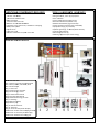
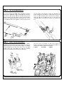
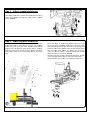
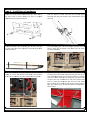
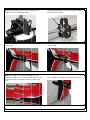
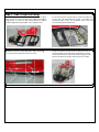
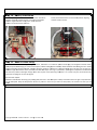
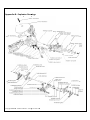
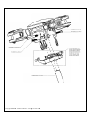
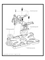
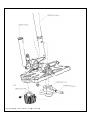
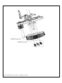
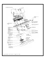
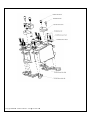
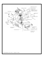
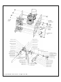
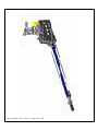
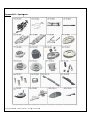
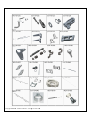
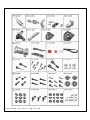
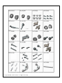
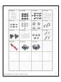
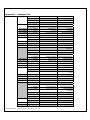
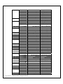
Co
o mp
m pa
ac
ct
tor
r Manual Distributted by CCPM SC
CALE RC H
HELICOPTTER Compactor 700 Manual – AS350 Release 1.0 ‐ January 2013 Roban Limited Dryriver Industrial Zone, Venture Cross Rd. Jiaolian, Wanjiang City District of Dongguan, 523046 Dongguan County (GD) ‐ PRC Copyright@2013 - Roban Limited – All rights reserved
SPECIFICATIONS Body length: 1650mm Length incl. rotors: 1920mm Width: 355mm Height: 480mm Main rotor diameter: 1560mm Main blade length: 700mm Tail rotor diameter: 280mm Tail blade length: 105mm Main shaft diameter: 12mm Tail shaft diameter: 5mm Spindle diameter: 8mm Battery compartment: 2x 60x60x180mm Motor:* 1x 750MX 450KV brushless outrunner, 12S capable 1x 120A brushless, 12S capable Speed controller:* Servo:* 3x metal gear cyclic, 1x 9g metal gear tail servo Battery:* 44.4V 5000mAh 35C+ Flight time: 5 minutes Takeoff weight: 7200g Flight Stabilization:* 3 axis flybarless gyro Radio Control:* min. 6 channel with pitch and throttle curves *) Optionally available equipment The Compactor is a high performance radio controlled scale helicopter. Our goal was to create a simple, high performance helicopter, with a minimum of mechanical components and simple maintenance. Please read this user manual carefully, it contains instructions for the correct assembly of the model. Please refer to the web site www.robanmodel.com for updates and other important information. Thank you for your purchase, and have a great time with your Compactor! Roban Limited IMPORTANT NOTES *This radio controlled helicopter is not a toy. *This radio controlled helicopter can be very dangerous. *This radio controlled helicopter is a technically complex device which has to be built and handled very carefully. *This radio controlled helicopter must be built following these instructions. This manual provides the necessary information to correctly assemble the model. It is necessary to carefully follow all the instructions. *Inexperienced pilots must be monitored by expert pilots. *All operators must wear safety glasses and take appropriate safety precautions. *A radio controlled helicopter must only be used in open spaces without obstacles, and far enough from people to minimize the possibility of accidents or of injury to property or persons. *A radio controlled helicopter can behave in an unexpected manner, causing loss of control of the model, making it very dangerous. *Lack of care with assembly or maintenance can result in an unreliable and dangerous model. *Neither Roban Limited nor its agents have any control over the assembly, maintenance and use of this product. Therefore, no responsibility can be traced back to the manufacturer. You hereby agree to release Roban Limited from any responsibility or liability arising from the use of this product. SAFETY GUIDELINES *Fly only in areas dedicated to the use of model helicopters. *Follow all control procedures for the radio frequency system. *It is necessary that you know your radio system well. Check all functions of the transmitter before every flight. *The blades of the model rotate at a very high speed; be aware of the danger they pose and the damage they may cause. *Never fly in the vicinity of other people. NOTES FOR ASSEMBLY Please refer to this manual for assembly instructions for this model. Follow the order of assembly indicated. The instructions are divided into chapters, which are structured in a way that each step is based on the work done in the previous step. Changing the order of assembly may result in additional or unnecessary steps. Use thread lockers and retaining compounds as indicated. In general, each bolt or screw that engages with a metal part requires thread lock. Factory pre‐assembled components have been assembled with all the required thread lock and lubricants, and have passed quality control. It is not necessary to disassemble and re‐assemble them. Copyright@2013 - Roban Limited – All rights reserved
AD
DDITIONA
AL COMPO
ONENTS R
REQUIRED TOOLS, LLUBRICAN
NTS, ADH
HESIVES *Elecctric Motor: 10SS‐12S – 400‐6
600Kv, pin
nion shaft diam
meter 6mm *Spe
eed controllerr: minimum 120A to be safe *Battteries: 10‐12SS 4000‐5000m
mAh *1 flybarless 3 axis control unit, suitable for scale flying dio power systtem *Rad
*3 cyyclic servos *1 taail rotor servo
o *6 ch
hannel radio ccontrol system
m on 2.4 GHz *Generic plieers *Hexagonal d
driver, size 1.5
5,2,2.5,3,4mm
m *4mm T‐Wreench *5.5mm Sockket wrench (fo
or M3 nuts) *8mm Hex fo
ork wrench (fo
or M5 nuts) *Medium thrreadlocker (egg. Loctite 243)) *Strong retaining compound (eg. Loctitee 648) *Spray lubricant (eg. Try‐Flow Oil) *Synthetic grrease (eg. Tri‐FFlow Synthetic Grease) *Cyanoacrylaate adhesive
*Pitch Gaugee (for set‐up)
*Soldering eq
quipment (forr motor wiringg) de the main
n box there are:
a
Insid
de the main box:
Insid
Box 1: Main Frame/Tail Frame//Rotorhead des, Tail bladees, Rods Box 2: Boom, Blad
pit Box 3: Scale Cockp
Bag 1: Tail fin rod Bag 2
2: Position light controller Bag 3
3: Scale fittinggs, screws Bag 4
4: Tail boom aaccessories Bag 5
5: Fuselage sccale fittings Bag 6
6: Mechanical fittings, screws Bag 7
7: Tail Wings Bag 8
8: Belt drive p
pulley Bag 9
9: Battery trayy Bag 10: EVA tail distancer Bag 11: Footrests Bag 12: Front window (inside co
ockpit) Mastter Pack 4: Fro
ont scale fusee (Bag 6 insidee) Mastter Pack 5: Tail boom (all otther bags) Mastter Pack 6: Alu
uminum landiing gear Asssembly
The mechanics aree almost entirrely preassem
mbled and splitt up into four sections: roto
orhead, main frame, tail fraame and tail tube. t scale fuseelage, the meechanics havee to be entireely assembled
d, electronic components installed, Priorr to the instaallation into the adjusted and testeed. After instaallation into th
he fuselage m
most of the helicopter mech
hanic become inaccessible. Ste
ep 1 – Rottorhead Slidee the rotorheead onto thee main shaft. Use screw (70‐
0000
06) and nylon
n nut (70‐00007) to secure the rotorh
head onto
o the main shaft. Use two screws (70‐00008) to addittionally clamp
p up the rotorr hub onto thee shaft as show
wn. Make sure th
he distance be
etween the ball link and th
he L lever is equally at 24mm. Finallly snap on the ball links (7
70‐00025) hplate’s upperr disc uni‐linkss (70‐00030). on the swash
ep 2 – Tail boom Ste
First of all install the center bearings (70
0‐00100) with
h the holders (02‐02006
6) into the taail boom (70‐0
00095). Distribute the bearings even
nly in the tail boom. It is recommendeed to applyy a bit of lubrificant on
nto the tubees inner surface, elsew
wise the bearring is likely to t get stuck b
before the correct posittion is reach
hed. Then install the cen
nter support ring (600
0UH1‐007), thee servo rod gu
uides (70‐000
040) and the sservo two tail servo hollders (70‐0009
98). Install the tail torque tube 00096) into th
he tail tube. (70‐0
m into the taail boom holders (70‐
Then insert the tail boom
0094). Lock th
he tube in pllace with scre
ew M3x8 00093, 70‐00
(70‐00086) via v the clamp
p up and ad
dditionally wiith screw M3x6 (70‐000
053) as shown. Install the carbon suppo
ort beams (70‐00104‐70
0‐00106) on the t main fram
me and the tail t boom tail boom clamp (600UH1‐‐007). Ste
ep 3 – Tail Servo In
nstallation
First of all, mount the holde
er frame (70‐‐00097) onto
o the m holders (70
0‐00098) usingg screw M3x8
8. Then mountt the boom
tail servo of you
ur choice into
o the tail fraame using screws uts as shown.. Install the sservo M3x10, washers and nylon nu
n and the supp
plied uniball. TThen slide thee tail rotor control horn
rod (70‐00103) in
nto the four gguides. Install the ball link (70‐) on both end
ds of the taill rotor control rod. Distriibute the guides evenlyy along the taail boom. Theen install the tail rotor frame onto the t tail boom
m. Lock it with the three screws s
as shown, but do d not use th
hread lock yeet, as it has got g to be uninstalled aagain. Snap th
he servo control rod onto
o the ball link. Ste
ep 4 – Cycclic Servo
o Installattion Instaall the three ccyclic servos onto the servvo tray as sho
own. Depeending on your servos, you may have to t use washers to adjust the servo to
o the proper iinstallation heeight. It is stro
ongly recommended to
o use metal servo horns and only m
metal gearred servos. The T
multi blaade rotor heead can feedback forcees that may leead to failure o
of plastic com
mponents. Copyright@2013
3 - Roban Lim
mited – All rig
ghts reserved
d
After the servos are installed, you will have to adjust the elow. The linkage rods length’s according to the sschematics be
distances aree uniball centeer to uniball ceenter: 1=81mm
2=112mm
m 3=81
1mm Ste
ep 5 – Adjjust swasshplate lin
nkages
The linkages from
m the L‐Leverss to the swash
h plate have tto be a correct len
ngth. Distancees are uniball center to un
niball set at center: 1=35mm Ste
ep 6 – Mo
otor and B
Belt instaallation In orrder to installl the motor, yyou must firstt disassemblee one of th
he side framees in order to
o have accesss to the moun
nting screw
ws and accesss to the belt drive. Hencee one side fraames fasteeners are nott tightened upon delivery.. Before instaalling the p
pinion pulley on the motorr, you have to
o add a flat to
o the moto
or shaft in ord
der to secure the pulley w
with the set screws (70‐)). 1 Mount the motor m
as show
wn using wasshers and screws onto the motor mount m
(70‐000
066). Make su
ure to have the motor wire outlet faacing into the right directio
on for connectting them to the ESC. Th
hen insert thee belt pulley in
nto the belt an
nd slide it onto the mo
otor shaft. Beefore you tigghten the set screws, make sure th
hat the pinion is installed leveled with
h the belt pulley, the distance (Fig. 1)) is at 24.5mm
m. Use both tensioning screw
ws to tension tthe belt drive. The belt mustn’t be teensioned too ttight to avoid unnecessary wear. After installattion of the mo
otor, reassemble the side frames. Step 7 – Electrical Wiring and Setup The mechanics have to be fully electrically setup and adjusted prior to installation into the fuselage. As the use of a 12S (44.4V) setup is necessary, we strongly recommend to run the control equipment on a separate 2S Lipo battery and BEC for security reasons. In scale configurations main battery power wires may be longer than on comparable 3D helicopter equipment. As HV ESCs do not necessarily have the main battery ground wire connected to the servo signal ground wire, it may be necessary to create an additional connection between the BEC 2S batteries ground wire and the 12S main battery ground wire. Certain configurations without this ground interconnection have led to a loss of signal at the ESC from the receiver due to EMC effects. The swash plate is a regular 120deg CCPM type, please take your time to adjust all servo travels, center positions – the entire 3 axis gyro – servo – radio setup prior to the installation into the fuselage. A 450KV motor such as the Align 750MX run at app. 80% throttle (hover) shows satisfying results. As space is limited, please make sure you check the dimensions if you intend to use other brand motors. In regards to the gyro setup, we recommend to start with standard values of the 3 axis gyro. Make sure you install the gyro in a way that provides easy access for connecting your programming equipment. As the scale fuselage adds additional inertia to each axis, gyros are normally to be set at a lower gyro gain. All in all, a rigid gyro response does ruin the scale look in flight. Before operating the model check the following points: ‐The direction of servo rotation (including the throttle function) and travels. ‐The direction of effect of the gyro, and the transmitter mixer functions you have programmed. ‐Collective pitch travel (linear travel ‐2/‐3° to +9/+10°) ATTENTION ! When using the a pitch gauge to adjust correct CP travels, make sure that the gauge lines up with the flat surface of the rotor blade. Many pitch gauges do not show the correct !
angle when snapped onto unsymmetric rotor blades The main rotor blades are not symmetrical. Do not try to fly inverted. ‐ It is permissible to reduce servo travels, but not below 60% (in this case adjust the mechanical linkage); travels should be primarily symmetrical. ‐ Apply collective pitch min. / collective pitch max. and full roll and pitch‐axis commands simultaneously in all directions; rotate the rotor head at the same time, and check that at the extremes of travel no part of the rotor head is obstructed. ‐ The auto‐rotation switch must be assigned, and within easy reach! ‐ When auto‐rotation is selected: throttle position to off, all directions of control and travels as in normal flight, tail rotor to 0° = fixed value. ‐The first few batteries should be flown with the model close to the ground, i.e. no more than about 1 m altitude, until you are confident that there are no defects or errors, and that everything is working faultlessly: ‐ Use your ears critically (!), listening for unusual sounds and vibration, and seek out the problem if you are in any doubt at all! ‐ Don’t listen to anyone standing close by if they try to hurry you into flying the model. ‐ Avoid hovering outside ground effect (hover altitude with a model: approx. 1m, or half the rotor disc diameter): ‐ Hovering requires very high power, and you are completely dependent on the motor: in contrast to most full‐size helicopters, model helicopters have only one (!) power plant. Ste
ep 8 – Insttallation of mechaanics Mou
unt the four LL‐brackets (60
0UH1‐003) on
nto both sidees of the main frame as shown. Make M
sure they are prop
perly ned before you fasten the sscrews. align
Take the en
ntire tail roto
or frame offf the tail tub
be again. Dismantle the main rotor blades if you
u installed the
em during the setup. Instaall the footressts onto the laanding gear ass shown. Use glue at a later stage to
o fix them in p
position, when fitting the o
other scalee accessories. Slidee the mechaanics into the fuselage. The aft bracckets engaage in a slot in the wooden frame workk. In the frontt use screw
w (70‐) and w
washer (70‐) to
o lock the mecchanics in placce. nding gear intto the fuselagge’s openings and lock Insert the lan
them in placce with screw
w (70‐) and washer w
(70‐) as a shown inside the wo
oodwork. Glue both tail wings into the tail boom
m. It is imporrtant that you align them in the prop
per angle while the glue curres. If you have a few bo
ooks handy, yyou can easily use them as a support structure in o
order make su
ure the wingss stay in posittion while the glue cures. We recom
mmend to usse thick cyan
noacrylate ood two comp
ponent glue that cures faast. Make glue or a go
sure you wipe off any exceessive glue. R
Route all three
e position o the front, as a they will become b
inacce
essible in light wires to
the next step
p. Instaall the spacerss that keep the engine houssing at a safe distaance from the swashplate aas shown. Slip the EVA ttail dampenerr unit onto thee tail boom be
efore installing the tail fuselage.
w insert the taiil frame with tthe screws set in into the taail Now
rotor housing. Install the tail frame on thee torque tubee through the access wn. holes as show
w use six screw
ws to mount th
he tail boom o
on the front Now
fuselage as shown
n. Use a 1mm drill to drill th
hrough. Then glue wooden spaceers supplied in
nto the inside, matching the the w
hole. he tail fin usin
ng glue as shown. Install the spaacer wire in th
Ste
ep 9 – Scaale Cockp
pit and fitttings With
h the cockpitt doors open
ned, you can install the parts p
easily. Install the instrument panel p
first. We W recommen
nd to leavee glueing it in later on, ass it provides sspace for hidiing a coun
nterweight forr CG adjustmeent. Then instaall the seats. using glue. Usee a de‐burringg Instaall the antennas as shown u
tool to widen the installation holes if too small. If you intend to have use pilot figures, leave the con
ntrol stick a
the figu
ures are instaalled. Use out for now and install after ment panel, seats s
and transparent glue to glue the instrum
control stickss onto the floo
or board. Install the antennas and w
wire cutter as sshown. We do
o not n cyanoacrylaate glue for surface recommend tthe use of thin
mount of painted parts. Th
he fumes of th
he curing glue
e leave white stains o
on the clearco
oat, which aree hard to remo
ove. Ste
ep 10 ‐ Baattery installation The battery comp
partment conssists of a convenient and seecure wooden structuree, a battery drawer. First locck you batteriies onto
o the supplied drawers usin
ng velcro. Then
n shove the draw
wer into the frramework stru
ucture. Finally securee the drawers into the locke
ed position byy using another velcrro as shown.
Ste
ep 11 ‐ No
ow it is time to flyy For tthe first few ccircuits: starting from grou
und effect, acccelerate to a moderate speeed in level fllight, and onlyy then initiate
e a climb, alwaays keep the m
model flying at a brisk forward speed; on
n the landing aapproach alwaays descend ttowards the laanding area att a steady angle
e (around 45°°) directly into
o wind, and do
on’t bring the model to a haalt until it is in
n ground effecct again. This way you can ssave your mod
del through au
utorotation. Iff one particulaar technical faault keeps recurring in yourr model, replaacing the com
mponent conce
erned will not ssolve the problem unless yyou change so
ome other aspect of the operating cond
ditions. It is as hard to fly nice and smo
ooth scale maneuvers as flyin
ng F3C or exact 3D figures. And one final requ
uest: Pleasse be realisticc when assessing your pilotting skills, because a scale h
helicopter is h
heavy and hen
nce much less agile in respo
onse than any 3D helicopterr. Keep this comparison c
in
n mind: if you
u can’t swim and you divee into deep water, w
the chaances are thatt you will wn. drow
Copyright@2013
3 - Roban Lim
mited – All rig
ghts reserved
d
Appendix A
A – Explossion Draw
wings Copyright@2013
3 - Roban Lim
mited – All rig
ghts reserved
d
Copyright@2013
3 - Roban Lim
mited – All rig
ghts reserved
d
Copyright@2013
3 - Roban Lim
mited – All rig
ghts reserved
d
Copyright@2013
3 - Roban Lim
mited – All rig
ghts reserved
d
Copyright@2013
3 - Roban Lim
mited – All rig
ghts reserved
d
Copyright@2013
3 - Roban Lim
mited – All rig
ghts reserved
d
Copyright@2013
3 - Roban Lim
mited – All rig
ghts reserved
d
Copyright@2013
3 - Roban Lim
mited – All rig
ghts reserved
d
Copyright@2013
3 - Roban Lim
mited – All rig
ghts reserved
d
Copyright@2013
3 - Roban Lim
mited – All rig
ghts reserved
d
Appendix B – Sparep
parts Copyright@2013
3 - Roban Lim
mited – All rig
ghts reserved
d
Copyright@2013
3 - Roban Lim
mited – All rig
ghts reserved
d
Copyright@2013
3 - Roban Lim
mited – All rig
ghts reserved
d
Copyright@2013
3 - Roban Lim
mited – All rig
ghts reserved
d
Copyright@2013
3 - Roban Lim
mited – All rig
ghts reserved
d
Appendix C – Sparepart List RCH‐70‐001
RCH‐70‐002
RCH‐70‐003
RCH‐70‐004
RCH‐70‐005
RCH‐70‐006
RCH‐70‐007
RCH‐70‐008
RCH‐70‐009
RCH‐70‐010
RCH‐70‐011
RCH‐70‐012
RCH‐70‐013
RCH‐70‐014
RCH‐70‐015
RCH‐70‐016
RCH‐70‐017
RCH‐70‐018
RCH‐70‐019
RCH‐70‐020
RCH‐70‐021
RCH‐70‐022
RCH‐70‐023
RCH‐70‐024
1‐JJ‐70‐00147
1‐JJ‐70‐00148
1‐JJ‐70‐00149
1‐JJ‐70‐00150
1‐JJ‐70‐00099
11‐600UH1‐003
1‐JJ‐70‐00152
1‐JJ‐70‐00153
1‐JJ‐70‐00058
1‐JJ‐70‐00071
1‐JJ‐70‐00066
1‐JJ‐70‐00067
1‐JJ‐70‐00062
1‐JJ‐70‐00061
1‐JJ‐70‐00063
1‐JJ‐70‐00075
Sideframes
Aft frame
Bottom frame
Fwd frame
Distancer 6x62
L‐Bracket
Landing Gear
Footrest
Upper base plate
Lower base plate
Motor holder
Screw M3x30
Main Gear 78T
Main gear hub
Spur Gear 20T
Washer 10x12x0.5
1‐JJ‐70‐00076
1‐JJ‐70‐00077
1‐JJ‐70‐00078
1‐JJ‐70‐00079
1‐JJ‐70‐00080
1‐JJ‐70‐00082
1‐JJ‐70‐00083
1‐JJ‐70‐00073
1‐JJ‐70‐00037
1‐JJ‐70‐00038
1‐JJ‐70‐00039
Bearing 10x15x5
One way bearing 10x14x12
Belt pulley 78T
Washer 10x12x1
Gear 1M 36T
Gear hub 36T
Gear holder 30T
Belt pinion 22T
Ball link 5mm
Lever 1
Flanged bearing 3x7x3
1‐JJ‐70‐00060
1‐JJ‐70‐00074
1‐JJ‐70‐00033
1‐JJ‐70‐00057
1‐JJ‐70‐00026
1‐JJ‐70‐00027
1‐JJ‐70‐00028
1‐JJ‐70‐00029
Distancer 10x25.1
Collar 12mm
Main Shaft 12mm
Shaft 10x76.1
Ball joint 22mm
Swash upper ring
Bearing 30x42x7
Swash lower ring
1‐JJ‐70‐00030
1‐JJ‐70‐00031
1‐JJ‐70‐00032
1‐JJ‐70‐00003
1‐JJ‐70‐00004
1‐JJ‐70‐00001
1‐JJ‐70‐00017
Ball head
Washer 2x8x1
Screw M2x6
Rotorhead top
Rotorhead bottom
Rotorhead Cap
Grip Spindle
Copyright@2013 - Roban Limited – All rights reserved
Seitenrahmen hintere Platte Bodenplatte vordere Platte Distanzstück 6x62 L‐Halter Fahrwerk Trittleiste Obere Basisplatte Untere Basisplatte Motorhalter Schraube M3x30 Hauptzahnrad 78T Hauptzahnradaufnahme Ritzel 20T Beilagschreibe 10x12x0.5 Kugellager 10x15x4 Kugellager 10x14x12 Riemenrad 78T Beilagscheibe 10x12x1 Zahnrad 1M 36T Zahnradaufnahme 36T Zahnradaufname 30T Riemenscheibe 22T Kugelkopfrahmen 5mm Hebel 1 Kugellager Flansch 3x7x3 Abstandshalter 10x25.1 Hauptwelle 12mm Welle 10x76.1 Kugelgelenk 22mm Taumelscheibe Oberteil Kugellager 30x42x7 Taumelscheibe Unterteil Kugelkopf Beilagscheibe 2x8x1 Schraube M2x6 Rotorkopf oben Rotorkopf unten Rotorkopfkappe Blattlagerwelle RCH‐70‐025
RCH‐70‐026
RCH‐70‐027
RCH‐70‐028
RCH‐70‐029
RCH‐70‐030
RCH‐70‐031
RCH‐70‐032
RCH‐70‐033
RCH‐70‐034
RCH‐70‐035
RCH‐70‐036
RCH‐70‐037
RCH‐70‐038
RCH‐70‐039
RCH‐70‐040
RCH‐70‐041
RCH‐70‐042
RCH‐70‐043
RCH‐70‐044
RCH‐70‐045
RCH‐70‐046
1‐JJ‐70‐00020
1‐JJ‐70‐00021
1‐JJ‐70‐00022
1‐JJ‐70‐00023
1‐JJ‐70‐00019
1‐JJ‐70‐00018
1‐JJ‐70‐00024
1‐JJ‐70‐00025
1‐JJ‐70‐00012
1‐JJ‐70‐00014
1‐JJ‐70‐00016
Washer 3x9x1.5
Bearing 3x7x3
Washer 3x4.5x1.1
L‐Lever
Screw M3x25
Self Locking Nut M3
Screw M2.5x16
Ball link 5mm
Washer 4x8x1
Washer 8x14x0.5
Washer 8x11.5x1.3
1‐JJ‐70‐00009
1‐JJ‐70‐00034
1‐JJ‐70‐00035
1‐JJ‐70‐00036
1‐JJ‐70‐00046
1‐JJ‐70‐00047
1‐JJ‐70‐00050
1‐JJ‐70‐00041
1‐JJ‐70‐00042
1‐JJ‐70‐00044
1‐JJ‐70‐00049
1‐JJ‐70‐00051
1‐JJ‐70‐00064
1‐JJ‐70‐00065
1‐JJ‐70‐00068
1‐JJ‐70‐00088
1‐JJ‐70‐00087
1‐60‐WJ‐00003
1‐JJ‐70‐00092
1‐JJ‐70‐00093
1‐JJ‐70‐00094
1‐JJ‐70‐00095
1‐JJ‐70‐00096
12‐02‐02006
11‐600jRCH‐70‐
002 1‐JJ‐70‐00097
1‐JJ‐70‐00098
1‐JJ‐70‐00102
1‐JJ‐70‐00103
1‐JJ‐70‐00104
1‐JJ‐70‐00105
1‐JJ‐70‐00106
11‐600UH1‐007
Main Blade Grip
Lever 23mm
Lever 67mm
Gestänge 98mm
Right servo lever
Left servo lever
Bearing Block
Lever 2
Lever 3
Bushing 5x7x7
Washer 5x7x1.5
Shaft 5x62
Servo holder fwd
Servo holder aft
Uniball 5mm
Bearing block
Tail shaft 5x83
Tube bevel gear
Washer 15x18x1
Tail boom holder fwd
Tail boom holder aft
Tail boom
Tail boom shaft
Bearing holder
X Junction
Beilagscheibe 3x9x1.5 Kugellager 3x7x3 Beilagscheibe 3x4.5x1.1 L‐Hebel Schraube M3x25 Stoppmutter M3 Schraube M2.5x16 Kugelkopf 5mm Beilagscheibe 4x8x1 Beilagscheibe 8x14x0.5 Beilagscheibe 8x11.5x1.3 Hauptrotorblatthalter Gestänge 23mm Gestänge 67mm Gestänge 98mm Rechter Servohebel Linker Servohebel Lagerbock Hebel 2 Hebel 3 Buchse 5x7x7 Beilagschreibe 5x7x1.5 Welle 5x62 Servohalter vorne Servohalter hinten Uniball 5mm Lagerbock Welle 5x83 Kegelrad Beilagscheibe 15x18x1 Heckrohrhalter vorne Heckrohrhalter hinten Heckrohr Heckrohrwelle Kugellagerhalter X‐Verbinder Tail servo frame
Tail servo clamp
Gear 1M 30T
Tail pushrod 702mm
Tail support holder
Bolt 1.5x7.8
Tail support rod
Tail support clamp
Heckservorahmen Heckservoklammer Zahnrad 1M30T Gestänge 702mm Strebenaufnahme Bolzen 1.5x7.8 Heckstrebe Heckstrebenklammer Copyright@2013 - Roban Limited – All rights reserved
RCH‐70‐047
RCH‐70‐048
RCH‐70‐049
RCH‐70‐050
RCH‐70‐051
RCH‐70‐052
RCH‐70‐053
RCH‐70‐054
RCH‐70‐055
RCH‐70‐056
RCH‐70‐057
RCH‐70‐058
RCH‐70‐059
RCH‐70‐060
RCH‐70‐061
RCH‐70‐062
RCH‐70‐063
RCH‐70‐064
RCH‐70‐065
RCH‐70‐066
RCH‐70‐067
RCH‐70‐068
RCH‐70‐069
RCH‐70‐070
RCH‐70‐071
RCH‐70‐072
RCH‐70‐073
RCH‐70‐074
RCH‐70‐075
RCH‐70‐076
RCH‐70‐077
RCH‐70‐078
1‐60‐WJ‐00010
1‐60‐WJ‐00011
1‐60‐WJ‐00006
1‐JJ‐70‐00121
1‐60‐WJ‐00002
1‐JJ‐70‐00110
1‐JJ‐70‐00111
1‐JJ‐70‐00112
1‐JJ‐70‐00113
1‐JJ‐70‐00122
1‐JJ‐70‐00107
1‐JJ‐70‐00108
1‐JJ‐70‐00125
1‐JJ‐70‐00126
1‐JJ‐70‐00130
1‐JJ‐70‐00123
1‐JJ‐70‐00114
1‐JJ‐70‐00115
1‐JJ‐70‐00116
1‐JJ‐70‐00119
1‐JJ‐70‐00117
1‐JJ‐70‐00120
1‐JJ‐70‐00118
1‐JJ‐70‐00136
1‐JJ‐70‐00154
1‐JJ‐70‐00151
1‐JJ‐70‐00146
1‐JJ‐70‐00002
1‐JJ‐70‐00005
1‐JJ‐70‐00006
1‐JJ‐70‐00007
1‐JJ‐70‐00008
1‐JJ‐70‐00010
1‐JJ‐70‐00011
1‐JJ‐70‐00013
1‐JJ‐70‐00015
1‐JJ‐70‐00040
1‐JJ‐70‐00045
1‐JJ‐70‐00054
1‐JJ‐70‐00055
1‐JJ‐70‐00056
1‐JJ‐70‐00081
1‐JJ‐70‐00084
1‐JJ‐70‐00085
1‐JJ‐70‐00086
Copyright@2013 - Roban Limited – All rights reserved
Washer 5x7x5.7
Washer 5x7x2.1
Tail shaft 2 blade
Washer 16x18x9.6
Tail frame gear
Center hub
Pitch lever
Pitch slider
Pitch sleeve
Washer 7x8.5x4
Dog bone
Washer 2x3x4
Sleeve 2x5x9.5
Washer 2x5x0.5
Screw M2x17
Support
Washer 3x4x0.5
L‐Lever
Washer 3x4x5
Frame spacer
Tail frame 1
Tail frame 2
Tail rotor hub
Tail blade
Tail blade
Main Blade
Main Belt
Screw M3x18
Screw M2.5x12
Screw M4x24‐6.5
Self Locking Nut M4
Screw M3x12
Screw M4x26‐7
Screw M4x10
Thrust Bearing 6x14x5
Bearing 8x14x4
Servo rod guide
Bearing 5x10x4
Screw M2.5x8
Bearing 12x24x6
Bearing 10x19x5
Nylon Nut M2.5
Screw M2.5x8
Screw M2.5x20
Screw M3x8
Hülse 5x7x5.7 Beilagscheibe 5x7x2.1 Heckwelle 2 Blatt Hülse 16x18x9.6 Kegelrad Heck Heckrotorkopf Pitchhebel Pitchschieber Pitchhülse Hülse 7x8.5x4 Hundeknochen Hülse 2x3x4 Hülse 2x5x9.5 Beilagscheibe 2x5x0.5 Schraube M2x17 Halterung Beilagscheibe 3x4x0.5 L‐Hebel Hülse 3x4x5 Distanzstück Heckrahmen 1 Heckrahmen 2 Heckhalter Heckrotorblatt Heckrotor Hauptrotorblatt Zahnriemen Schraube M3x18 Schraube M2.5x12 Paßschraube M4x24‐6.5 Stoppmutter M4 Schraube M3x12 Paßschraube M4x26‐7# Schraube M4x10 Drucklager 6x14x5 Kugellager 8x14x4 Gestängeführung Kugellager 5x10x4 Schraube M2.5x8 Kugellager 12x24x6 Kugellager 10x19x5 Nylon Mutter M2.5 Schraube M2.5x8 Schraube M2.5x20 Schraube M3x8 RCH‐70‐079
1‐JJ‐70‐00090
1‐JJ‐70‐00133
1‐JJ‐70‐00100
1‐JJ‐70‐00101
1‐JJ‐70‐00109
1‐JJ‐70‐00124
1‐JJ‐70‐00127
1‐JJ‐70‐00128
1‐JJ‐70‐00131
1‐JJ‐70‐00132
1‐JJ‐70‐00134
1‐JJ‐70‐00135
rotor head 4 blade top
rotor head 4 blade bottom
Bearing 7x11x3
Bearing 3x6x2.5
Blade grip
Bearing 5x10x4
Screw M3x8
Screw M3x20
Screw M2x10
Screw M2x5
rotor head 5 blade top
rotor head 5 blade bottom
RCH‐70‐091
RCH‐70‐092
RCH‐70‐093
RCH‐70‐094
RCH‐70‐095
RCH‐70‐096
RCH‐70‐097
1‐JJ‐70‐00138
1‐JJ‐70‐00139
1‐JJ‐70‐00140
Sleeve 2x5x6.5
Ball Link
Screw M2x14
1‐JJ‐70‐00142
1‐JJ‐70‐00143
1‐JJ‐70‐00144
1‐JJ‐70‐00145
1‐60‐WJ‐00015
Uniball 5mm
Pitch lever 4 blade
Pitch lever 3 blade
Tail shaft 3/4 blade
Washer 12x18x0.1
RCH‐70‐098
1‐JJ‐70‐00043
Set screw M4x4
RCH‐70‐099
RCH‐70‐100
RCH‐70‐101
RCH‐70‐102
RCH‐70‐103
RCH‐70‐104
RCH‐70‐105
RCH‐70‐106
1‐JJ‐70‐00053
1‐JJ‐70‐00052
1‐JJ‐70‐00048
1‐JJ‐70‐00059
1‐JJ‐70‐00069
1‐JJ‐70‐00091
1‐60‐WJ‐00004
1‐JJ‐70‐00089
Screw M3x6
Washer 3x7x0.5
Ball link 5mm
Screw M3x10
Nut M2
Bearing 12x18x4
Shaft bevel gear
Washer 10x13x0.1
RCH‐70‐107
RCH‐70‐108
RCH‐70‐109
RCH‐70‐110
1‐JJ‐70‐00129
1‐JJ‐70‐00141
1‐JX‐47‐00115
1‐JX‐47‐00103
Nylon Nut M2
Tail spindle
Rotor hub 3 blade
Rotor hub 4 blade
RCH‐70‐080
RCH‐70‐081
RCH‐70‐082
RCH‐70‐083
RCH‐70‐084
RCH‐70‐085
RCH‐70‐086
RCH‐70‐087
RCH‐70‐088
RCH‐70‐090
Copyright@2013 - Roban Limited – All rights reserved
Rotorkopf 4 Blatt oben Rotorkopf 4 Blatt unten Kugellager 7x11x3 Kugellager 3x6x2.5 Rotorblatthalter Kugellager 5x10x4 Schraube M3x8 Schraube M3x20 Schraube M2x10 Schraube M2x5 Rotorkopf 5 Blatt oben Rotorkopf 5 Blatt unten Hülse 2x5x6.5 Kugelkopfverbinder Schraube M2x14 Uniball 5mm Pitchhebel 4 Blatt Pitchhebel 3 Blatt Heckwelle 3/4 Blatt Beilagscheibe 12x18x0.1 Madenschraube M4x4 Schraube M3.6 Beilagscheibe 3x7x0.5 Kugelkopf 5mm Schraube M3x10 Mutter M2 Kugellager 12x18x4 Kegelrad 20T Beilagscheibe 10x13x0.1 Nylon Mutter M2 Heckrotor Welle Rotorkopf 3 Blatt Rotorkopf 4 Blatt NOTES: Copyright@2013 - Roban Limited – All rights reserved
www.robanmodel.com www.scaleflying.com Copyright@2013 - Roban Limited – All rights reserved