1
INSTALLATION MANUAL
IM-WM1-0302-McQuay
Group: WALL MOUNTED
Part Number: A08019025673
Date: MARCH 2002
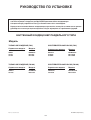
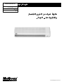
WALL MOUNTED
SPLIT TYPE AIR CONDITIONER
© 2002 McQuay International
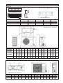
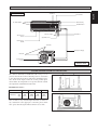
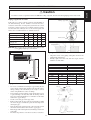
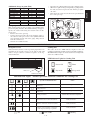
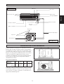
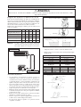
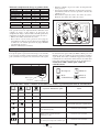
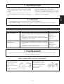
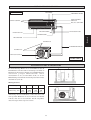
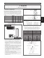
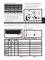
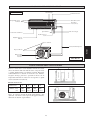
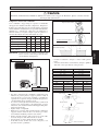
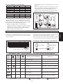
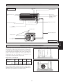
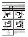
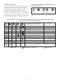
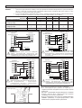
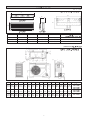
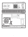
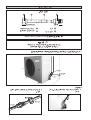
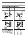
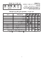
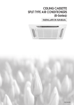
OUTLINE AND DIMENSIONS
Indoor Unit
A
All dimensions are in mm / (in)
C
D
TOP VIEW
B
E
FRONT VIEW
INSTALLATION PLATE
SIDE VIEW
Dimension
WM071 / 101 / 151 / 1R
WM201 / 201R
WM 251 / 251R / 301 / 311 / 301R
A
785,0 (30,9)
1050,0 (41,3)
1200,0 (44,1)
B
297,0 (11,7)
320,0 (12,6)
360,0 (14,2)
C
174,0 (6,85)
190,0 (7,5)
200,0 (7,9)
D
595,0 (23,4)
730,0 (28,7)
730,0 (28,7)
E
280,0 (11,0)
311,0 (12,2)
347,0 (13,7)
A
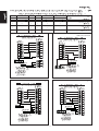
All dimensions are in mm / (in)
N
5 (0,2)
C
39 (1,5)
15 (0,6)
M
R
15 (0,6)
39 (1,5)
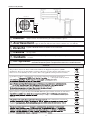
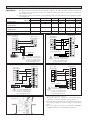
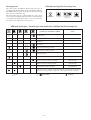
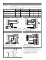
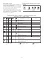
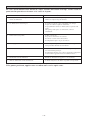
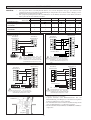
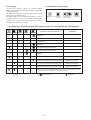
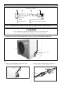
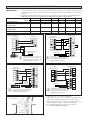
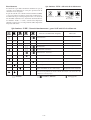
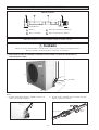
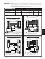
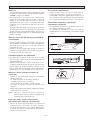
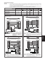
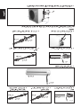
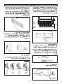
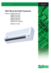
Outdoor Unit (SL-Series)
5 (0,2)
P
Q
P
C
840 (33,1)
160 (6,3)
H
B
Dimension
07B / 07BR
10B / 10BR
15B / 15BR
20B / 20BR
25B / 25BR
30B / 30BR
A
B
C
D
E
F
740
494 270
266 233
(29,1) (19,4) (10,6) (10,5) (9,2)
28C / 28CR
G
H
L
J
K
L
K
20 (0,8)
20 (0,8)
20 (0,8)
(2,6)
65 J
E
F
141 (5,6)
2,5 (0,1)
G
D
M
N
P
Q
R
474
47
(18,7) (1,9)
55
65
(2,2) (2,6)
166
(6,5)
92
(3,6)
348
318
129 482 68,5
(13,7) (12,5) (5,1) (19,0) (2,7)
840
646 330
297 309
626
41
(33,1) (25,4) (13,0) (11,7) (12,2) (24,6) (1,6)
85
75
(3,3) (3,0)
177
(7,0)
106
(4,2)
408
378
124 592 78,5
(16,1) (14,9) (4,9) (23,3) ( 3 , 1 )
855
750 328
303 309
730
49
(33,7) (29,5) (12,9) (11,9) (12,2) (28,7) (1,9)
116
75
(4,6) (3,0)
187
(7,4)
98
(3,9)
392
362
126 603 164
(15,4) (14,3) (5,0) (23,7) (6,5)
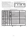
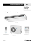
Outdoor Unit (SL071 & 10/15 C/CR)
All dimensions are in mm / (in)
Dimension
071 / 1R
A
B
C
D
E
F
G
H
I
J
K
L
M
N
O
600 (23,6) 475 (18,7) 245 (9,6) 418 (16,4) 177 (6,9) 35 (1,3) 93 (3,6) 81 (3,1) 83 (3,2) 55 (2,2) 398 (15,6) 101 (3,9) 97 (3,8) 17 (0,6) 22 (0,8)
10 / 15 C /CR 700 (27,5) 521 (20,5) 250 (9,8) 485 (19,1) 175 (6,8) 36 (1,4) 95 (3,7) 93 (3,6) 86 (3,3) 68 (2,6) 441 (17,3) 130 (5,1) 111 (4,3) 15 (0,5) 18 (0,7)
i
141,5 (5,57)
448 (17,64)
141,5 (5,57)
20 (0,79)
Outdoor Unit (SL30C)
850 (33,46)
20 (0,79)
1030 (40,55)
40 (1,57)
400 (15,75)
320 (12,60)
40 (1,57)
50 (1,97)
25 (0,98)
85 (3,35)
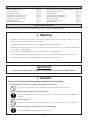
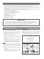
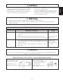
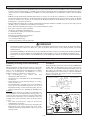
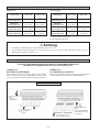
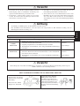
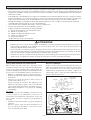
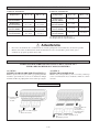
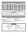
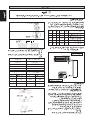
! Caution
Sharp edges and coil surfaces are potential locations which may cause
injury hazards. Avoid from being in contact with these places.
! Avertissement risque de blessure. Mieux vaut éviter le contact avec ces endroits.
Les bords coupants et les surfaces du refroidisseur tuulaire présentent un
! Vorsicht
Scharfe Kanten und Wärmetauscherflächen stellen eine Gefahrenquelle dar.
Jeglicher Kontakt mit diesen Stellen ist zu vermeiden.
! Cautela
Per preservarsi da eventuali ferite, evitare di toccare gli spigoli afilati e la superficie
dei serpentini.
! Cuidado
Los Bordes afilados y la superficie del serpentín pueden producir lesiones. Evite
tocarlos.
! Осторожно
Острые края и поверхности змеевиков являются потенциальными
местами нанесения травм. Остерегайтесь контакта с этими местами.
NOTICE
This product is subjected to Waste of Electrical and Electronic Equipment Regulations (WEEE
Regulations). The waste product shall be separately collected by specific collection and treatment centre.
Please refer to local authorithy for these centres. This is only applicable to European Union countries.
Ce produit est soumis à la réglementation concernant les déchets des équipements électriques et
électroniques (ré
r
é
ê
é séparé
r ment par un centre de collecte
é
é
ître ces centres. Ceci
éenne.
Gerää
ä
ätes
getrennt vom Hausmüll bei Ihrer örtlichen Mülldeponie bzw. Ihrem örtlichen
äändiges Abfall-Amt. Dieser
Hinweis gilt nur fü
f r Länder
ä
der Europäischen Union.
Questo prodotto è soggetto alle disposizioni RAEE (Rifiuti di apparecchiature elettriche ed elettroniche).
à
à locali. Questa disposizione è valida solamente i paesi
dell’U.E.
ñ
éctrico y Electrónico en materia de
í
ífico
á
de colecció
solamente aplicable a los países de la Unión Europea.
данного
по
ii
и
.
правила
,
Европейского
ii
. Эти
.
English
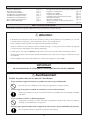
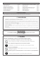
INSTALLATION MANUAL
This manual provides the procedures of installation to ensure a safe and good standard of operation for the air
conditioner unit.
Special adjustment may be necessary to suit local requirements.
Before using your air conditioner, please read this instruction manual carefully and keep it for future reference.
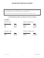
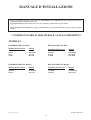
WALL MOUNTED SPLIT TYPE AIR CONDITIONER
MODEL
COOLING UNIT (R22)
HEAT PUMP UNIT (R22)
Reference Model
Model
Reference Model
Model
WM301
SL30C
SL30B
MWM030F
MLC30C
MLC30B
WM301R
SL30CR
SL30BR
MWM030FR
MLC30CR
MLC30BR
COOLING UNIT (R410A)
HEAT PUMP UNIT (R410A)
Reference Model
Model
Reference Model
Model
5WM311
5SL28C
M5WM031F
M5LC28C
5WM301R
5SL28CR
M5WM030FR
M5LC28CR
IM-WM1-0302(2)-McQuay
Part No.: A08019025673
1-1
CONTENTS
- Outline and Dimensions
- Safety Precautions
- Installation Diagram
- Installation of the Outdoor Unit
- Installation of the Orifice Pipe
- Installation of the Indoor Unit
- Refrigerant Piping
- Electrical Wiring Connection
page i-ii
page 2
page 3
page 3
page 4
page 6
page 7
page 8
- Special Precautions When Dealing With R410A Unit
- Vacuuming and Charging
- Indicator Lights
- Air Conditioner Unit Operation
- Standard Operating Conditions
- Electrostatic Filter
- Service and Maintenance
- Troubleshooting
page 10
page 10
page 11
page 13
page 14
page 14
page 15
page 16
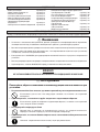
SAFETY PRECAUTIONS
Before installing the air conditioner unit, please read the following safety precautions carefully.
! Warning
•
Installation and maintenance should be performed by qualified persons who are familiar with local code and
regulation, and experienced with this type of appliance.
•
All field wiring must be installed in accordance with the national wiring regulation.
•
Ensure that the rated voltage of the unit corresponds to that of the name plate before commencing wiring work
according to the wiring diagram.
•
The unit must be GROUNDED to prevent possible hazard due to insulation failure.
•
All electrical wiring must not touch the refrigerant piping, compressor or any moving parts of the fan motors.
•
Confirm that the unit has been switched OFF before installing or servicing the unit.
IMPORTANT
DO NOT INSTALL OR USE THE AIR CONDITIONER UNIT IN A LAUNDRY ROOM.
! Caution
Please take note of the following important points when installing.
• Do not install the unit where leakage of flammable gas may occur.
If gas leaks and accumulates at the surrounding of the unit, it may cause fire ignition.
• Ensure that the drainage piping is connected properly.
If the drainage piping is not connected properly, it may cause water leakage which will dampen the
furniture.
• Do not overcharge the unit.
This unit is factory pre-charged. Overcharge will cause over-current or damage to the compressor.
• Ensure that the units panel is closed after service or installation.
Unsecured panels will cause the unit to operate noisily.
1-2
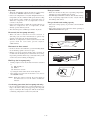
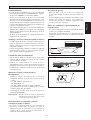
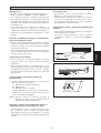
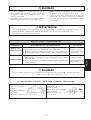
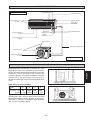
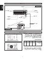
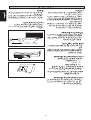
Indoor Unit
Air Filters
Front Frame
Back Housing
Air Intake Grille
On/Off Switch
Drain Hose
Indicator Lights
Air Discharge
Louver
Signal Receiver
Air Discharge
Grille
Air Intake
Refrigerant Piping
Air Intake
Air Discharge
Nozzle
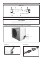
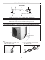
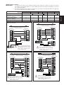
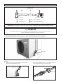
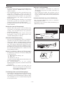
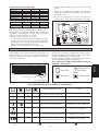
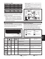
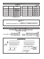
Outdoor Unit
B
Obstacle
A
Discharge Air
Obstacle
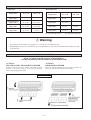
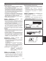
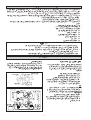
The outdoor unit must be installed in such a way, so as to
prevent short circuit of the hot discharged air or obstruction
to the smooth air flow. Please follow the installation clearance shown in the figure. Select the coolest possible place
where intake air temperature is not greater than the outside
air temperature (maximum 45°C/113°F).
Return Air
INSTALLATION OF THE OUTDOOR UNIT
C
D
300
(11.8)
1000
(39.4)
300
(11.8)
500
(19.7)
Note: If there is any obstacle higher than 2m, or if there is
any obstruction at the upper part of the unit, please allow
more space than the figure indicated in the above table.
1-3
C
D
Obstacle
B
Service Access
A
Obstacle
Dimension
Minimum
Distance, mm
(in)
Return Air
Installation clearance
English
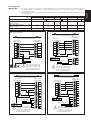
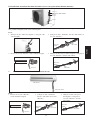
INSTALLATION DIAGRAM
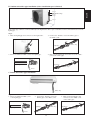
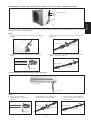
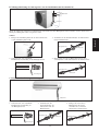
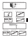
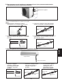
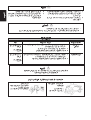
INSTALLATION OF ORIFICE PIPE
Orifice Pipe
2
3
4
1
Outdoor Unit
Indoor
1
Orifice
3
Flare nut 3/8" (Female)
2
Pipe, connecting
4
Flare joint 3/8" (Male)
Note: This installation is only for WM301 / SL30B & WM301 / SL30C
! Caution
The orifice pipe must be installed in the correct direction as shown above.
Improper direction may cause failure to the operating system.
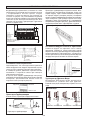
A. Outdoor unit orifice pipe installation (where installation space is wide enough)
Step 2
Orifice Pipe
Step 1
Steps:
1. Directly connect the “Female” nut of the orifice pipe to
the liquid valve.
2. Flare the liquid pipe and connect it to the “Male” joint
of the orifice pipe.
Liquid Pipe
Orifice Pipe
1-4
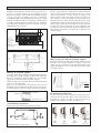
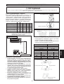
B. Outdoor unit orifice pipe installation (where installation space is limited)
Step 4
English
Orifice Pipe
Step 3
Step 2
Step 1
If the orifice pipe cannot be connected directly to the liquid valve due to space constraint, it can be connected in between of the
liquid pipe.
Steps:
1. Flare the liquid pipe and connect it to the liquid valve.
3. Connect the “Female” nut of the Orifice pipe to
the“Male” joint.
Orifice Pipe
Liquid Pipe
2. Braze an additional “Male” joint to the liquid pipe.
4. Flare another liquid pipe and connect it to the “Male”
joint of the orifice pipe.
Liquid Pipe
Liquid Pipe
Orifice Pipe
Brazer
C. Indoor unit orifice pipe installation
Indoor Unit
Orifice Pipe
Steps:
1. Braze an additional “Male” joint
to the liquid pipe.
2. Connect the “Female” nut of the
Orifice pipe to the“Male” joint.
Orifice Pipe
Liquid Pipe
3. Flare another liquid pipe and
connect it to the “Male” joint
of the orifice pipe.
Liquid Pipe
Liquid Pipe
Orifice Pipe
Brazer
1-5
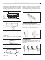
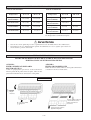
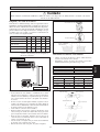
INSTALLATION OF THE INDOOR UNIT
The refrigerant piping can be routed to the unit in a
number of ways (left or right from the back of the unit), by
using the cut-out holes on the casing of the unit (see figure).
Bend the pipes carefully to the required position in order to
aligned it with the holes. For the right hand and rear side
out, hold the bottom of the piping and then position it to the
required direction (see figure). The condensation drain hose
can be taped to the pipes.
The indoor unit must be installed in such a way so as to
prevent short circuit of the cool discharged air with the hot
return air. Please follow the installation clearance shown in
the figure. Do not place the indoor unit where there could be
direct sunlight shining on it. Also, this location must be
suitable for piping and drainage, and be away from doors or
windows.
50mm
50mm
50mm
50mm
50mm
50mm
Right & rear side routing
Higher Than
Eye Level
Air Flow
Direction
Maintenance &
Servicing Space
Installation plate
Mount the unit onto the installation plate
Hook the indoor unit onto the upper portion of the
installation plate (Engage the two hooks at the rear top of
the indoor unit with the upper edge of the installation plate).
Ensure that the hooks are properly seated on the
installation plate by moving it to the left and right.
Marking-offline
Thread
Mounting installation plate
Ensure that the wall is strong enough to withstand the weight
of the unit. Otherwise, it is necessary to reinforce the wall
with plates, beams or pillars.
Use the level gauge for horizontal mounting, and fix it with
4 suitable screws.
In case the rear piping draws out, drill a hole 65mm in
diameter with a cone drill, slightly lower on the outside wall
(see figure).
Connecting cable
Drain hose
Water drainage piping
Inside
Outside
The indoor drain pipe must be in a downward gradient for
smooth drainage. Avoid situations that are likely to cause
water to leak.
1/50 Inclination
Water Drainage
Routing of piping
Remove the screw holding the front panel.
Water
Leaking
Water
Leaking
3
2
1
Piping routing
Water
Leaking
End
Dipped
Into
Water
4
5
1-6
✓
j
J
J
J
Correct
Wrong
Wrong
Wrong
! Caution
An orifice is used as expansion device in WM301 cooling only unit. It is fixed in the liquid pipe in the indoor unit.
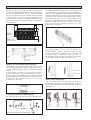
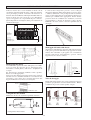
Piping length and elevation
Cutting copper tube
If the pipe is too long, both the capacity and reliability of
the unit will drop. As the number of bends increases,
resistance to the flow of refrigerant system increases, thus
lowering cooling capacity. As a result the compressor may
become defective. Always choose the shortest path and
follow the recommendations as tabulated below:
Model
Maximum length, m (ft), L
07/10
15
20
25
30
12 (39.4) 12 (39.4) 15 (49.2) 15 (49.2) 35 (114.8)
Maximum elevation m (ft), H 5 (16.4) 5 (16.4)
8 (26.2)
8 (26.2) 15 (49.2)
Maximum number of bends
10
10
10
10
10
Liquid pipe size
1/4"
1/4"
1/4"
3/8"
3/8"
Gas pipe size
3/8"
1/2"
5/8"
5/8"
5/8"
Remove burr
Copper tube
Swaging block
Remark: The refrigerant pre-charged in the outdoor unit
is for piping length up to 7.62m/25ft.
Indoor unit
Piping connection to the units
•
•
Align the center of the piping and tighten the flare nut
sufficiently with fingers.
Finally, tighten the flare nut with the torque wrench
until the wrench clicks.
Pipe Size mm / (in)
L
Torque Nm / (Ft-lb)
6.35 (1/4)
9.53 (3/8)
12.7 (1/2)
15.88 (5/8)
H
18
42
55
65
Ø Tube, D
Outdoor unit
A (mm)
Inch
mm
Imperial
Rigid
1/4"
3/8"
1/2"
5/8"
6.35
9.52
12.70
15.88
1.3
1.6
1.9
2.2
0.7
1.0
1.3
1.7
Piping works
•
•
•
•
•
•
•
Do not use contaminated or damaged copper tubing. Do not
remove plastic, rubber plugs and brass nuts from the valves,
fittings, tubings and coils until you are ready to connect
suction or liquid line into valves or fittings.
If any brazing work is required, ensure that the nitrogen gas
is passed through coil and joints while the brazing work is
being done. This will eliminate soot formation on the inside
walls of the copper tubings.
Cut the connection pipe with a pipe cutter.
Remove burrs from cut edges of the pipes with remover. Hold
the end of the pipe downwards to prevent metal chips from
entering the pipe.
Insert the flare nuts, mounted on the connection parts of both
the indoor unit and outdoor unit onto the copper pipes.
Flare the pipe with extra length above the flaring tool as shown
in the table.
The flared edge must be even and not cracked or scratched.
Flare Joint
Flared Tube
Indoor Piping
Flare Nut
Torque Wrench
Spanar
1-7
(13.3)
(31.0)
(40.6)
(48.0)
English
REFRIGERANT PIPING
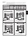
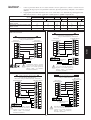
ELECTRICAL WIRING CONNECTION
Cooling unit
IMPORTANT : *
The figures shown in the table are for information purpose only. They should be checked and selected
to comply with the local/national codes of regulations. This is also subject to the type of installation
and conductors used.
** The appropriate voltage range should be checked with label data on the unit. ETL listed is only applicable to 60Hz
power supply only.
Model
Indoor
Outdoor
WM 071/ 101/ 151
SL07/ 10/ 15B
Voltage range**
WM201/ 251/ 301
SL20/ 25/ 30B
220V-240V/ 1Ph/ 50Hz +
5WM311
5SL28C
WM301
SL30C
or 208V-230V/ 1Ph/ 60Hz +
WM201/ 251/ 301
SL20/ 25/ 30B
WM301
SL30C
380V-415V/ 3Ph/ 50Hz +N+
Power supply cable size*
Number of wires
mm2
1.5
3
2.5
3
2.5
3
4
3
1.5
5
1.5
5
Interconnection cable size*
Number of wires
mm2
1.5
3
2.5
3
2.5
3
2.5
4
1.5
4
1.5
4
A
15
20
20
25
15
15
Recommended fuse
WM301 VS SL30C
WM07 / 10 / 15 / 20 / 25 / 301 VS SL07 / 10 / 15 / 20 / 25 / 30B
5WM311 VS 5SL28C
Indoor Unit
Outdoor Unit
Terminal Block
Terminal Block
Indoor Unit
Terminal Block
Outdoor Unit
Terminal Block
COMP
COMP
COMP
N2
N
L
N
N2
S
N1
R
N1
L
COMP
L
L
Power Supply Cable
Power Supply Cable
!
N
!
There must be a double pole
switch with a minimum 3mm
contact gap and fuse/circuit
breaker as recommended in
the fixed installation circuit.
WM201 / 251 VS SL20 / 25B (3 Phase)
Indoor Unit
Terminal Block
WM301 VS SL30C (3 Phase)
Outdoor Unit
Terminal Block
COMP
N2
There must be a double pole
switch with a minimum 3mm
contact gap and fuse/circuit
breaker as recommended in
the fixed installation circuit.
Indoor Unit
Terminal Block
COMP
Outdoor Unit
Terminal Block
COMP
L
COMP
L
N
N2
N
N1
N1
R
L
L
R
S
S
T
Power Supply Cable
Power Supply Cable
N
T
N
!
!
There must be a double pole
switch with a minimum 3mm
contact gap and fuse/circuit
breaker as recommended in
the fixed installation circuit.
There must be a double pole
switch with a minimum 3mm
contact gap and fuse/circuit
breaker as recommended in
the fixed installation circuit.
• All wires must be firmly connected.
• All wires must not touch the refrigerant piping,
compressor or any moving parts of the fan motor.
• The connecting wires between the indoor unit and the outdoor
unit must be clamped on the wire clamps as shown in the
figure.
• The power supply cord must be equivalent to H05RN-F
(245IEC57) which is the minimum requirement.
Wire Clamp
Interconnection
Cable
1-8
Heat pump unit
The figures shown in the table are for information purpose only. They should be checked and selected
to comply with the local/national codes of regulations. This is also subject to the type of installation
and conductors used.
** The appropriate voltage range should be checked with label data on the unit. ETL listed is only applicable to 60Hz
power supply only.
Model
Indoor WM 071/ 101/ 151 R WM201/ 251/ 301 R 5WM301R WM301 R WM201/ 251/ 301 R WM301 R
Outdoor
SL07/ 10/ 15BR
SL20/ 25/ 30BR
5SL28CR SL30CR
SL20/ 25/ 30BR
SL30CR
Voltage range**
220V-240V/ 1Ph/ 50Hz +
or 208V-230V/ 1Ph/ 60Hz +
380V-415V/ 3Ph/ 50Hz +N+
Power supply cable size*
Number of wires
mm2
1.5
3
2.5
3
2.5
3
4
3
1.5
5
1.5
5
Interconnection cable size*
Number of wires
mm2
1.5
5
2.5
5
2.5
5
2.5
6
1.5
6
1.5
4
A
15
20
20
25
15
15
Recommended fuse
WM301R VS SL30CR
WM07 / 10 / 15 / 20 / 25 / 301R VS SL07 / 10 / 15 / 20 / 25 / 30BR
5WM301R VS 5SL28CR
Outdoor Coil Sensor Connection Wire
(8m long) attached in the indoor unit
Outdoor Unit
Terminal Block
Indoor Unit
A
Terminal Block
Outdoor Coil Sensor Connection Wire
(8m long) attached in the indoor unit
Indoor Unit
Terminal Block
Outdoor Unit
Terminal Block
4WV
4WV
OF
OF
COMP
COMP
N2
N1
N
4WV
4WV
OF
OF
COMP
COMP
N2
L
N1
N
L
L
Power Supply Cable
Power Supply Cable
N
L
!
There must be a double pole
switch with a minimum 3mm
contact gap and fuse/circuit
breaker as recommended in
the fixed installation circuit.
!
WM201 / 251R VS SL20 / 25BR (3 Phase)
There must be a double pole
switch with a minimum 3mm
contact gap and fuse/circuit
breaker as recommended in
the fixed installation circuit.
WM301R VS SL30CR (3 Phase)
Outdoor Coil Sensor Connection Wire
(8m long) attached in the indoor unit
Indoor Unit
Outdoor Unit
Terminal Block
Terminal Block
4WV
4WV
OF
OF
COMP
COMP
N2
L
N1
N
Outdoor Coil Sensor Connection Wire
(8m long) attached in the indoor unit
Outdoor Unit
Terminal Block
Indoor Unit
A
Terminal Block
4WV
4WV
OF
OF
COMP
COMP
N2
L
N1
N
L
L
R
R
S
Power Supply Cable
S
T
T
Power Supply Cable
N
!
!
There must be a double pole
switch with a minimum 3mm
contact gap and fuse/circuit
breaker as recommended in
the fixed installation circuit.
1-9
There must be a double pole
switch with a minimum 3mm
contact gap and fuse/circuit
breaker as recommended in
the fixed installation circuit.
N
English
IMPORTANT : *
SPECIAL PRECAUTIONS WHEN DEALING WITH R410A UNIT
•
•
•
•
•
•
R410A is a near azeotrope refrigerant blend of hydro fluorocarbon (HFC) which is environmental friendly. It has Zero
Ozone Depletion Potential (ODP=0) and this conforms to Montreal Protocol regulations. It has no flame propagation and
a low toxic refrigerant (rated as A1 by ARI). R410A is a mixture of R32 (50%) and R125 (50%).
POE oil is used as lubricant for R410A compressor, which is different from the mineral oil used for R22 compressor.
During installation or servicing, extra precaution must be taken not to expose the R410A system too long to moist air.
Residual POE oil in the piping and components can absorb moisture from the air.
Refrigerant R410A is more easily affected by dust of moisture compared with R22, make sure to temporarily cover the
ends of the tubing prior to installation.
No additional charge of compressor oil only is permitted.
No refrigerant other than R410A is permitted.
Tools designed specifically for R410A only.
i) Manifold gauge and charging hose
ii) Gas leak detector
iii) Refrigerant cylinder/charging cylinder
iv) Vacuum pump c/w adaptor
v) Flare tools
vi) Refrigerant recovery machine
! CAUTION
•
•
•
R410A must be charged as liquid. Usually R410A cylinder is equipped with a dip-pipe for liquid withdrawal.
If there is no dip-pipe, the cylinder should be inverted so as to withdraw liquid R410A from the valve.
Do not top-up when servicing leak, as this will reduce the unit performance. Vacuum the unit thoroughly and then
charge the unit with fresh R410A according to the amount recommended in the specification.
Do not touch the compressor or refrigerant piping when the chiller is running. If necessary wear protective gloves.
VACUUMING AND CHARGING
Purging the piping and the indoor unit
Additional charge
Except for the outdoor unit which is pre-charged with
refrigerant, the indoor unit and the refrigerant
connection pipes must be air-purged because the air
containing moisture that remains in the refrigerant cycle may
cause malfunction of the compressor.
• Remove the caps from the valve and the service port.
• Connect the centre of the charging gauge to the vacuum
pump.
• Connect the charging gauge to the service port of the
3-way valve.
• Start the vacuum pump. Evacuate for approximately 30
minutes. The evacuation time varies with different
vacuum pump capacity. Confirm that the charging gauge
needle has moved towards -76mmHg (0~76mmHg).
Caution
If the gauge needle does not move to 0~76mmHg, be
sure to check for gas leaks (using the refrigerant
detector) at flare type connection of the indoor and outdoor unit and repair the leak before proceeding to the
next step.
• Close the valve of the changing gauge and stop the
vacuum pump.
• On the outdoor unit, open the suction valve (3 way) and
liquid valve (2 way) (in anti-clockwise direction) with
4mm key for hexagon sacked screw.
The refrigerant is pre-charged in the outdoor unit. If the
piping length is less than 7.62m (25 ft), then additional
charge after vacuuming is not necessary. If the piping length
is more than 7.62m (25 ft), then use the additional charge
valve as indicated in the table below.
Service Port
Indoor Unit
Refrigerant Piping
Flare Unit
Allen Key
Outdoor Unit
3 Ways Valve
Liquid Side
Discharge
Valve
Close
Gas Side
Suction
Valve
Open
Vacuum
Pump
Close
Hi
Low
Close
1-10
Outdoor Unit
Model
071 / 101 / 151
201
251 / 301
071R / 101R /151R
201R
251R / 301R
10 m/32.8 ft
35
35
90
50
60
120
12 m/39.4 ft
65
65
165
90
110
220
15 m/49.2 ft
110
280
185
370
•
Additional charge in gram (R410A)
Model
311
301R
10 m/32.8 ft
80
110
12 m/39.4 ft
150
200
Open the gas cylinder and low pressure charging valve.
When the required refrigerant quantity is pumped into
the unit, close the low pressure side and the gas cylinder valve.
Disconnect the service hose from service port. Put back
the service port cap.
Indoor Unit
Liquid Side
Outdoor Unit
Discharge
Valve
15 m/49.2 ft
255
335
Close
Charge operation
Gas Side
This operation must be done by using a gas cylinder and a
precise weighing machine. The additional charge is toppedup into the outdoor unit using the suction valve via the
service port.
• Remove the service port cap.
• Connect the low pressure side of the charging gauge to
the suction service port center of the cylinder tank and
close the high pressure side of the gauge. Purge the air
from the service hose.
• Start the air conditioner unit.
Suction
Valve
Check
Valve
Low
Open
Close
Hi
Close
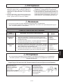
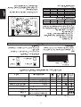
INDICATOR LIGHTS
IR signal receiver
Cooling unit
When an infrared remote control operating signal has been
transmitted, the signal receiver on the indoor unit will
make a <beep> sound to confirm acceptance of the signal transmission.
The table shows the LED indicator lights for the air
conditioner unit under normal operation and fault conditions.
The LED indicator lights are located at the bottom right side
of the air conditioner unit.
LED Indicator Lights for Cooling Unit
IR Receiver
Power ON
Timer
Dry mode
Sleep mode
LED Indicator Lights
LED Indicator Lights : Normal Operation And Fault Conditions For Cooling Unit
Operation / Fault Indication
Power
Dry
Timer
Sleep
Timer on.
–
Sleep mode on.
–
Dry mode.
–
Frost prevention.
Continuously
Action
Clean the filter and switch to high fan.
Room air sensor contact loose/short.
Call your dealer.
twice every 2 sec.
Indoor coil sensor contact loose/short.
Call your dealer.
Call your dealer.
3 times every 2 sec.
Sensor contact problem, compressor
overload protection trip or gas leak
once every 2 sec.
ON
ON or OFF
1-11
Blinking
English
•
•
Additional charge in gram (R22)
LED Indicator Lights For Heat Pump Unit
Heat pump unit
The table shows the LED indicator lights for the air
conditioner unit under normal operation and fault conditions.
The LED indicator lights are located at the bottom right
side of the air conditioner unit.
The heat pump units are equipped with an “auto” mode
sensor whereby it will provide reasonable room temperature
by switching automatically to either “cool” or “heat” mode,
according to the temperature set by the user.
Cooling mode
Dry mode
Heat/Fan mode
(red/green)
Sleep mode
LED Indicator Lights : Normal Operation And Fault Conditions For Heat Pump Unit
Normal Operation/Fault Condition
Cool
Dry
Fan
Heat
Action
Sleep
Cooling mode.
–
Dry mode.
–
Fan mode.
–
Heat mode.
–
Auto mode in heating operation.
–
Auto mode in cooling operation.
–
Defrost operation.
–
Compressor overload protection.
Call your dealer.
Indoor coil sensor contact loose/short.
Call your dealer.
Outdoor coil sensor contact loose/short.
Call your dealer.
Room air sensor contact loose/short.
Call your dealer.
If the system is in cool mode or heat mode (with the sleep function off), the sensor
may have a contact problem, compressor overload protection trip or gas leak.
ON
ON or OFF
1-12
Blinking
Dry mode
Frost prevention
• When the air humidity is high, the unit can operate in dry
mode. Press <MODE> button and choose <DRY>.
• If the room temperature is 2°C/35.6°F higher than the set
temperature, the air conditioner will operate under cooling
mode until it reaches within the 2°C/35.6°F range of
difference compared to the set temperature before it
converts to dry mode.
• If the room temperature is within the 2°C/35.6°F range of
difference compared to the set temperature, it will
directly operate under dry mode.
• The unit will operate at LOW speed under dry mode.
• When the air filter is dirty, the evaporating temperature
will decrease and eventually cause frosting.
• The LED light will blink to indicate that the filter is dirty.
If the evaporating temperature reaches -2°C/28.4°F, the
unit will trip and defrost.
Fan speed and rated cooling capacity
• The rated cooling capacity is provided at the maximum
fan speed.
• The cooling capacity is lower when the unit is operating at
MEDIUM and LOW fan speed.
Heat mode (for heat pump unit only)
• When the unit is switched on from cold start or
defrosting cycle, the indoor fan will start to operate only
after the coil reaches the desired temperature.
• When the set temperature is achieved, the indoor fan will
operate until the coil cannot provide anymore
additional heat.
Cooling
Dry
Horizontal
25°C/77°F
Horizontal air flow control
• For more effective air circulation, you can manually adjust
the air discharge grille to the left or right.
• During cool mode operation and dry mode operation, do
not direct the air discharge louver downwards for too long.
If operating continues in this way, condensation may occur
on the louver, thus resulting in drippings.
Hot Keep (for heat pump only)
•
•
During compressor cut off, the indoor fan can be switched
to
(i) ON (default) or
(ii) OFF or
(iii) Interval on and off
by setting the slide switch shown in the diagram.
The switch is located at the front frame cover (next to
the ON/OFF switch).
HOT KEEP
OFF
INTERVAL
ON
ON/OFF switch
NOTE : When the option is selected, the power supply of
the unit need to be reset in order to activate the
function.
Overheating protection (for heat pump unit only)
• In case the internal and/or the external temperature is to
high, or the filter is dirty and clogged up, the refrigerant
may be overheated. The compressor will cut out when the
condensing temperature reaches 62°C/143.6°F.
1-13
English
AIR CONDITIONER UNIT OPERATION
STANDARD OPERATING CONDITIONS
Heat Pump Unit
Cooling unit
Temperature
Ts °C/°F
Th °C/°F
Temperature
Minimum indoor
temperature
19.4 / 66.9
13.9 / 57.0
Minimum indoor
temperature
Maximum indoor
temperature
26.7 / 80.1
19.4 / 66.9
Maximum indoor
temperature
Minimum outdoor
temperature
19.4 / 66.9
13.9 / 57.0
Minimum outdoor
temperature
-8 / 17.6
-9 / 15.8
Maximum outdoor
temperature
46 / 114.8
24 / 75.2
Maximum outdoor
temperature
24 / 75.2
18 / 64.4
Ts °C/°F
Th °C/°F
10 / 50
-
26.7 / 80.1
-
Ts: Dry bulb temperature.
Th: Wet bulb temperature.
! Warning
• Disconnect from the main power supply before servicing the air conditioner unit.
• DO NOT pull out the power cord when the power is ON. This may cause serious electrical shocks which may result
in fire hazards.
ELECTROSTATIC FILTER
DUAL ACTION ELECTROSTATIC AIR PURIFYING
AND DEODORIZING FILTER MEDIA AND FILTER FRAME
ACTION 1ELECTROSTATIC AIR PURIFYING FILTER
ACTION 2DEODORIZING FILTER
Removes microscopic dust, smoke and small invisible
particles to keep the room air clean with pre-charged
electrostatic polypropylene filter.
Removes unwanted smells and odors in the air and keeps
the room air fresh with activated carbon filter.
HOW TO INSTALL
1-14
1. The electrostatic air purifying and deodorizing filter
should be replaced once every 6 months or when the
filter changes color to brownish, whichever is sooner.
2. Used dusty filters should be disposed and shouldn't be
reused, even if it has been cleaned and washed.
3. The filter is a consumable part which you can purchase
from your air conditioner dealer.
4. Use the new filter immediately once it has been taken
out from its sealed packing. Do not unpack the new
filter too early before it is actually used as this may
decrease its deodorizing effect.
! Warning
•
•
Disconnect from the main power supply before servicing the air conditioner unit.
DO NOT pull out the power cord when the power is ON. This may cause serious electrical shocks which may
result in fire hazards.
SERVICE AND MAINTENANCE
Service Parts
Maintenance Procedures
Indoor air filter
1. Remove any dust adhering to the filter by using a vacuum cleaner or
wash in lukewarm water (below 40°C/104°F ) with a neutral cleaning
detergent.
2. Rinse the filter well and dry before placing it back onto the unit.
3. Do not use gasoline, volatile substances or chemicals to clean the filter.
At least once
every 2 weeks.
1. Clean any dirt or dust on the grille or panel by wiping it off with a soft
cloth soaked in lukewarm water (below 40°C/104°F) and a neutral
detergent solution.
2. Do not use gasoline, volatile substances or chemicals to clean the
indoor unit.
At least once
every 2 weeks.
More frequently if
necessary.
Indoor unit
Period
More frequently if
necessary.
! Caution
Do not operate any heating apparatus too close to the air conditioner unit. This may cause the plastic panel to melt
or deform as a result of the excessive heat.
WHEN THE UNIT IS NOT USED FOR AN EXTENDED PERIOD OF TIME
Operate the unit for 2 hours
with the following setting.
Operating mode : cool
Temperature : 30°C/86°F
Remove the power plug.
If you are using an independent
electric circuit for your unit,
cut off the circuit.
Remove the batteries in the
remote control.
1-15
English
! Caution
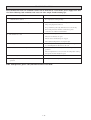
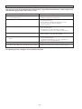
TROUBLESHOOTING
If any malfunction of the air conditioner unit is noted, immediately switch off the power supply to the unit.
Check the following fault conditions and causes for some simple troubleshooting tips.
Causes / Action
Fault
1. The compressor does not operate 3 minutes after the air
conditioner unit is started.
- Protection against frequent starting. Wait for 3 to 4 minutes for
the compressor to start operating.
2. The air conditioner unit does not operate.
- Power failure, or the fuse needs to be replaced.
- The power plug is disconnected.
- It is possible that your delay timer has been set incorrectly.
- If the fault persist after all these verifications, please
contact the air conditioner unit installer.
3. The air flow is too low.
- The air filter is dirty.
- The doors or windows are open.
- The air suction and discharge are clogged.
- The regulated temperature is not high enough.
4. Discharge air flow has bad odour.
- Odours may be caused by cigarettes, smoke particles, perfume
etc. which might have adhered onto the coil.
5. Condensation on the front air grille of the indoor unit.
- This is caused by air humidity after an extended period of
operation.
- The set temperature is too low, increase the temperature setting
and operate the unit at high fan speed.
6. Water flowing out from the air conditioner unit.
- Switch off unit and call dealer.
7. Hissing air flow sound from the air conditioner unit during
operation.
- Refrigerant fluid flowing into the evaporator coil.
If the fault persists, please call your local dealer/serviceman.
1-16
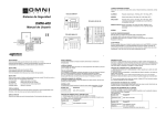
Ce manuel fournit les procédures d’installation pour assurer le bon fonctionnement et la sécurité de cet appareil.
Des ajustements peuvent être nécéssaires pour suivre les réglementations locales.
Avant d’installer et de faire fonctionner le climatiseur, lisez attentivement ce manuel et conservez le.
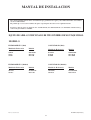
CLIMATISEURS SPLIT SYSTEM MONTAGE MURAL
MODÈLE
FROID SEUL (R22)
POMPE À CHALEUR (R22)
Modèle de Référence
Modèle
Modèle de Référence
Modèle
WM301
SL30C
SL30B
MWM030F
MLC30C
MLC30B
WM301R
SL30CR
SL30BR
MWM030FR
MLC30CR
MLC30BR
FROID SEUL (R410A)
POMPE À CHALEUR (R410A)
Modèle de Référence
Modèle
Modèle de Référence
Modèle
5WM311
5SL28C
M5WM031F
M5LC28C
5WM301R
5SL28CR
M5WM030FR
M5LC28CR
IM-WM1-0302(2)-McQuay
Part No.: A08019025673
2-1
Français
MANUEL D’INSTALLATION
SOMMAIRE
- Contour et Dimensions
- Précautions de Sécurité
- Diagramme D’installation
- Installation de L’unité Extérieure
- Installation du Tuyau D’orifice
- Installation de L’unité Intérieure
- Raccordements des Tuyauteries
- Raccordement Électrique
page i-ii
page 2
page 3
page 3
page 4
page 6
page 7
page 8
- Précautions Spéciales Pour Les Appareils au R410A
- Aspiration et Chargement
- L’indicateur S’allume
- Opération du Climatiseur
- Conditions Standard de Fonctionnement
- Filtre Électrostatique
- Entretien et Maintenance
- Analyse des Causes de Dysfonctionnement
du Climatiseur
page 10
page 10
page 11
page 13
page 14
page 14
page 15
page 16
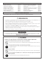
PRÉCAUTIONS DE SÉCURITÉ
Avant de faire fonctionner l’appreil, veuillez bien lire les précautions de sécurité suivantes.
! Attention
•
L’installation et la maintenance doivent être exécutées par une personne qualifiée qui est familiarisée avec les lois
et réglementations en vigueur, et aussi expérimentée dans ce type d’équipements.
•
Tous les câblages doivent répondre aux réglementations électriques nationales.
•
Avant de commencer le raccordement suivant le schéma électrique, s’assurer que la tension nominale de l’appareil
corresponde bien à celle indiquée sur la plaque signalétique.
•
L’ unité doit être raccordée à la TERRE pour prévenir tous les risques possibles dûes à un défaut d’isolation.
•
Aucun câble électrique ne doit toucher la tuyauterie du réfrigérant, le compresseur ou les pièces mobiles des moteurs
de ventilation.
•
Avant l’installation ou l’entretien du climatiseur, s’assurer que l’appareil est éteint (OFF).
IMPORTANT
NE PAS INSTALLER OU UTILISER LE CLIMATISEUR DANS UNE BUANDERIE.
! Avertissement
Vérifier les points suivants au cours de l’installation.
• Ne pas installer l’appareil où il peut se produire des fuites de gaz inflammable.
En cas de fuite et accumulation de gaz autour de l’appareil, il y a risque d’incendie.
• S’assurer que le tuyau d’évacuation du condensat est correctement branché.
Si le tuyau d’évacuation n’est pas correctement branché, les éventuelles fuites d’eau risquent de mouiller
le mobilier.
• Ne pas surcharger l’unité (en fluide frigorigène).
Cet appareil est préchargé en usine. Une charge trop importante risque de provoquer une surcharge
électrique ou d’endommager le compresseur.
• S’assurer que le panneau supérieur de l’appareil est remis en place après l’installation ou l’entretien.
Avec un panneau mal fixé l’appareil va fonctionner bruyamment.
2-2
DIAGRAMME D’INSTALLATION
Unité Intérieure
Filtre à air
Cadre Avant
Chassis Arriere
Grilles de reprise d’air
Français
Interrupteur ON/OFF
Tuyau D’evacuation
Led de Visualisation
Conduit de ventilation
Récepteur
de Signal
Grilles de Ventilation
Reprise Air
Tuyauteries Frigorifiques
Reprise Air
Refoulement d’air
Unité Extérieure
B
Obstacle
A
Refoulement
Obstacle
L’unité extérieure (ou groupe de condensation) doit être
instalée dans un endroit où aucun obstacle ne doit perturber
la circulation de l’air, aussi bien à l’aspiration qu’au
refoulement du ventilateur (risque de recyclage d’air chaud).
Respecter les dégagements minimum prévus (voir tableau
ci-dessous). Choisir un emplacement le moins exposé
possible à l’ensoleillement; l’entré d’air sur l’unité extérieure
ne devra pas être supérieure à la température ambiante
(maximum 45°C/113°F).
Entrée d’air
INSTALLATION DE L’UNITÉ EXTÉRIEURE
D
1000
(39,4)
300
(11,8)
500
(19,7)
Remarques : En cas d’obstacles de part et d’autre de l’unité
d’une hauteur supérieure à 2 mètres ou toute obstruction d’air
sur le dessus de l’unité, augmenter sensibelment les
dégagements minimum prévus.
2-3
C
D
Obstacle
C
Accès de service
B
Obstacle
Dimension
A
Minimum
Distance, mm
300
(Pouce) (11,8)
Entrée d’air
Dégagements minimum
INSTALLATION DU TUYAU D’ORIFICE
Tuyau d’orifice
2
3
4
1
Unité Extérieure
Intérieur
1
Orifice
3
Écrou évasé de 3/8 po (femelle)
2
Tuyau de raccord
4
Assemblage par évasement de 3/8 po (mâle)
Remarque: Cette installation ne vaut que pour WM301 / SL30B et WM301 / SL30C
! Avertissement
Le tuyau d’orifice doit être installé dans la bonne direction (illustration ci-dessus).
Une orientation incorrecte peut causer l’échec du système d'exploitation.
A. Installation de l’orifice du tuyau de l’unité extérieure (où l’espace pour l’installation est assez large)
Étape 2
Tuyau d’orifice
Étape 1
Étapes:
1. Raccorder directement l’écrou “Femelle” du tuyau
d’orifice sur le robinet de liquide.
2. Évaser le tuyau de liquide et le brancher au joint
“Mâle” du tuyau d’orifice.
Tuyau
d’orifice
2-4
Tuyau de
liquide
B. Installation de l’orifice du tuyau de l’unité extérieure (où l’espace pour l’installation est limité)
Étape 4
Tuyau d’orifice
Étape 3
Étape 2
Si le tuyau d’orifice ne peut pas être connecté directement au robinet de liquide à cause d’un manque d’espace, on peut
l’installer au milieu du tuyau de liquide.
Étapes:
1. Évaser le tuyau de liquide et le brancher au robinet de
liquide.
3. Raccorder l’écrou “Femelle” du tuyau d’orifice au joint
“Mâle”.
Tuyau de liquide
Tuyau d’orifice
2. Braser un joint “Mâle” supplémentaire au tuyau de
liquide.
4. Évaser un autre tuyau de liquide et le brancher au joint
“Mâle” du tuyau d’orifice.
Tuyau de liquide
Tuyau de liquide
Tuyau d’orifice
Braseur
C. Installation du tuyau d’orifice sur l’unité intérieure
Unité Intérieure
Tuyau d’orifice
Étapes:
1. Braser un joint “Mâle”
supplémentaire au tuyau de
liquide.
2. Raccorder l’écrou “Femelle” du
tuyau d’orifice au joint “Mâle”.
Tuyau de liquide
3. Évaser un autre tuyau de liquide
et le brancher au joint “Mâle” du
tuyau d’orifice.
Tuyau de liquide
Tuyau d’orifice
Tuyau de liquide
Tuyau d’orifice
Braseur
2-5
Français
Étape 1
INSTALLATION DE L’UNITÉ INTÉRIEURE
Installer l’unité intérieure de traitement d’air de façon à ce
qu’il n’y ait aucun obstacle sur la circulation de l’air
(risque de recyclage de l’air refroidi au refoulement de l’unité
et l’air à l’entrée). Veuillez respecter l’écartement
d’installation illustré sur le diagramme. Ne pas exposer l’unité
intérieure à l’influence directe de l’éclairage. L’emplacement
de l’unité, doit permettre une évacuation aisée des condensats,
et permettre une evacuation aisee des condensats, et doit être
suffisamment loin des portes.
50mm
L’unité d’évacuations des condensats de l’unité interieure
devra être, dans la mesure du possible, dirigé vers la sortie
arrière des tuyauteries à travers le mur de support (voir
figure). Avant d’orienter le tubing, déclipser le support de
tube. Cintrer les tubes frigorifiques avec précaution et les
diriger vers la sorte choisie. Ne pas oublier de passer le câble
d’alimentation électrique dans l’unité intérieure à travers le
mur en même temps que les tuyauteries. Ne pas raccorder
le câble. Laisser une longueur de câble suffisante pour
permettre la connection ultérieure. Relier ensemble les tubes
frigorifiques, le flexible d’évacuation des condensats et le
câble électrique.
50mm
50mm
Acheminement de la tuyauterie
Plus haut que le
niveau des yeux
Direction de
la circulation
d’air
Espace d’entretien et
de reparation
Plaque d’Installation
Mise en place de l’unite de la platine support
Positionner dans un premier temps l’unité intérieure sur la
languette d’accrochage supérieure de support. Pour vous
assurer que les crochets sont correctement installés sur la
plaque d’installation, essayez de les faire légèrement bouger
de gauche à droite.
Le Marquage-Hors ligne
Le fil
Montage de la platine support
S’assurrer que le mur de support soit suffisamment résistant,
pour supporter le poids de l’unité et éviter toutes vibrations.
Selon la composition du mur, utiliser des vis chevilles
appropriées pour la fixation de la platine support.
Utiliser la jauge à niveau pour le montage horizontal, puis la
fixer avec 4 vis appropriées.
Dans le cas de sortie arrière des tuyauteries, percer le trou
Ø 65mm pour les canalisations à l’aide d’une scie cloche. Le
trou aura une légère pente vers l’unité extérieure (Voir figure).
Câble de liaison
Tuyau d’evacuation
Évacuation des condensats
À l’extèrieur
À l’intèrieur
Le tube d’évacuation des condensats de l’unité devra être,
dans la mesure du possible, dirigé vers la sortie arriere des
tuyauteries a travers le mur de support. Evitez les
situations susceptibles de causer une fuite d’eau.
Inclinaison de 1/50
Orientation des tuyauteries
Drainage De L’eau
Retirer les vis qui retiennent le panneau de devant.
3
2
1
Acheminement de la tuyauterie
Fuite
d’eau
Fuite
d’eau
4
5
2-6
Fuite
d’eau
Evacuation
d’eau de
Condensation
plongé
dans l’eau
j
✓
J
J
J
Correct
Incorrect
Incorrect
Incorrect
RACCORDEMENTS DES TUYAUTERIES
! Attention
Dans l’unité de refroidissement WM301 on utilise un orifice, attaché à la tuyauterie d'eau de l’unité intérieure, comme
dispositif d’expansion.
Longueur des tuyauteries et différence de niveau
Coupe des Tubes Cuivre
Modèle
07/10
15
20
25
30
Longueur max, m (ft), L
12 (39,4) 12 (39,4) 15 (49,2) 15 (49,2) 35 (114,8)
Elevation max m (ft), H
5 (16,4) 5 (16,4) 8 (26,2) 8 (26,2) 15 (49,2)
Nombre de coude max
10
10
10
10
10
Ø racc. Tube liquide
1/4"
1/4"
1/4"
3/8"
3/8"
Ø racc. Tube aspiration
3/8"
1/2"
5/8"
5/8"
5/8"
Remarque:
Français
Pour un bon fonctionnement des unités, il est impératif de
respecter la longueur maximum des tuyauteries indiquée
dans le tableau ci-dessours, de respecter le nombre de coudes
maximum autorisé, et de ne pas dépasser la différence de
niveau entre l’unite intérieure et l’unite extérieure.
Tableau des caracteristiques valables pour les unites froid
seul et reversibles.
Ebavurage
Tube Cuivre
Dudgeonniere
La charge complète de gaz se trouve dans l’unité
extérieure jusqe’à une longueur nominale de 7,62 mètres/
25ft., aucun complément en réfrigérant n’est nécéssaire.
Raccordement de la tuyauterie aux unités
Unité Intérieure
•
Aligner les tubes et serrer l’écrou à la main d’abord.
•
Enfin, serrer l’écrou à l’aide d’une clef dynamométrique
jusqu’au clic.
Ø Tuyau mm / (pouce)
L
6,35 (1/4)
9,53 (3/8)
12,7 (1/2)
15,88 (5/8)
H
Pouce
1/4"
3/8"
1/2"
5/8"
Unité Extérieure
Ø Tube, D
mm
6,35
9,52
12,70
15,88
Couple Nm / (Ft-lb)
18
42
55
65
(13,3)
(31,0)
(40,6)
(48,0)
A (mm)
Impérial
Normal
1,3
0,7
1,6
1,0
1,9
1,3
2,2
1,7
Travail des tuyauteries
Raccord à visser
•
•
•
•
•
•
•
Ne pas utiliser de tuyauteries en cuivre encrassé ou
endommagé. Ne pas retirer les bouchons en plastique ou
caoutchouc et les écrous en laiton des vannes, raccords, tubes
et serpentins jusqu’à ce que les tuyauteries d’apiration ou de
liquide soient prêtes à être connectées aux vannes et raccords.
S’il est nécessaire de braser, s’assurer que de l’azote passe
dans les serpentins et raccords pendant le brasage, pour éviter
les dépôts de suie sur les faces intérieures des tubes de cuivre.
Couper le tuyau de raccordement avec un coupe-tube.
Ébarber les bords coupés des tuyaux à l’aide d’un alésoir. Tenir
l’extrémité du tuyau vers le bas pour empêcher la limaille
d’entrer dans le tuyau.
Relier les écrous ‘flare’ montés sur les connexions des unités
intérieure et extérieure aux tubes de cuivre.
Évaser le tuyau avec longueur supplémentaire au-dessus de
l’outil à évaser comme indiqué sur le tableau.
Le bord évasé doit être régulier et ne présenter aucune
craquelure ou éraflure.
Tube de l'unité Intérieure
Tube avec dudgeon
Ecrou
Clef Dynamométrique
Clef d'immobilisation
2-7
RACCORDEMENT ÉLECTRIQUE
Module refroidisseur
IMPORTANT : *
Ces valeurs sont données à titre indicatif seulement; elles doivent être vérifiées et ajustées en fonction
des normes et de la réglementations en vigueur. Elles dépendent aussi du type d’installation et du choix
des conducteurs utilisés.
** Le voltage adéquat doit être vérifié avec les données de l’étiquette sur l’appareil. ETL n’est applicable
que pour une alimentation électrique de 60Hz.
Modèle
Intérieure
Extérieure
WM 071/ 101/ 151
SL07/ 10/ 15B
Tension d’alimentation**
WM201/ 251/ 301
SL20/ 25/ 30B
220V-240V/ 1Ph/ 50Hz +
5WM311
5SL28C
WM301
SL30C
ou 208V-230V/ 1Ph/ 60Hz +
WM201/ 251/ 301
SL20/ 25/ 30B
WM301
SL30C
380V-415V/ 3Ph/ 50Hz +N+
Section du câble d’alim*
Nombre de conducteurs
mm2
1,5
3
2,5
3
2,5
3
4
3
1,5
5
1,5
5
Section du câble de liaison*
Nombre de conducteurs
mm2
1,5
3
2,5
3
2,5
3
2,5
4
1,5
4
1,5
4
A
15
20
20
25
15
15
Fusible aM
WM301 VS SL30C
WM07 / 10 / 15 / 20 / 25 / 301 VS SL07 / 10 / 15 / 20 / 25 / 30B
5WM311 VS 5SL28C
Bornier De
Bornier De
L’unité Intérieure
L’unité Extérieure
Bornier De
L’unité Intérieure
Bornier De
L’unité Extérieure
L
COMP
COMP
COMP
N2
N
N
N2
S
N1
R
N1
L
COMP
L
L
Cordon Electrique
Cordon Electrique
!
N
!
Il doit y avoir un interrupteur à double
pôles avec un intervalle de contact de
3mm minimum et un coupe-circuit/
fusible comme recommandé dans le
circuit d’installation fixe.
WM201 / 251 VS SL20 / 25B (3 Ph)
Bornier De
L’unité Intérieure
WM301 VS SL30C (3 Ph)
Bornier De
L’unité Extérieure
Bornier De
L’unité Intérieure
COMP
COMP
N2
Il doit y avoir un interrupteur à double
pôles avec un intervalle de contact de
3mm minimum et un coupe-circuit/
fusible comme recommandé dans le
circuit d’installation fixe.
Bornier De
L’unité Extérieure
COMP
L
COMP
L
N
N2
N
N1
N1
R
L
L
R
S
S
T
Cordon Electrique
Cordon Electrique
N
T
N
!
Il doit y avoir un interrupteur à double
pôles avec un intervalle de contact de
3mm minimum et un coupe-circuit/
fusible comme recommandé dans le
circuit d’installation fixe.
!
Il doit y avoir un interrupteur à double
pôles avec un intervalle de contact de
3mm minimum et un coupe-circuit/
fusible comme recommandé dans le
circuit d’installation fixe.
• Tous les fils doivent être fermement connectés.
• Aucun fils ne doivent toucher les tubes frigorifiques, le
compresseur ou une autre partie mobile du moteur de ventilateur.
• Le câble de liaison entre l’unité intérieure et extérieure
doit être fixé au boitier de raccordement à l’aide de
l’attache comme indiqué dans la figure ci-contre.
• Le cordon électrique doit être êquivalent à H05RN-F
(245IEC57) au minimum.
Pince A Fil
Câble De
Liaison
2-8
Module pompe à chaleur
IMPORTANT : *
Ces valeurs sont données à titre indicatif seulement; elles doivent être vérifiées et ajustées en fonction
des normes et de la réglementations en vigueur. Elles dépendent aussi du type d’installation et du choix
des conducteurs utilisés.
** Le voltage adéquat doit être vérifié avec les données de l’étiquette sur l’appareil. ETL n’est applicable
que pour une alimentation électrique de 60Hz.
Intérieure WM 071/ 101/ 151 R WM201/ 251/ 301 R 5WM301R WM301 R WM201/ 251/ 301 R WM301 R
Extérieure
SL07/ 10/ 15BR
SL20/ 25/ 30BR
5SL28CR SL30CR
SL20/ 25/ 30BR
SL30CR
Tension d’alimentation**
220V-240V/ 1Ph/ 50Hz +
ou 208V-230V/ 1Ph/ 60Hz +
380V-415V/ 3Ph/ 50Hz +N+
Section du câble d’alim*
Nombre de conducteurs
mm2
1,5
3
2,5
3
2,5
3
4
3
1,5
5
1,5
5
Section du câble de liaison*
Nombre de conducteurs
mm2
1,5
5
2,5
5
2,5
5
2,5
6
1,5
6
1,5
4
A
15
20
20
25
15
15
Fusible aM
WM301R VS SL30CR
WM07 / 10 / 15 / 20 / 25 / 301R VS SL07 / 10 / 15 / 20 / 25 / 30BR
5WM301R VS 5SL28CR
Câble De Liaison De La Sonde De
Température Obligatoire (longueur 8m) Fourni
Bornier De
Avec L’Unité Intérieure
L’unité Extérieure
Bornier De
Câble De Liaison De La Sonde De
Température Obligatoire (longueur 8m) Fourni
Avec L’Unité Intérieure
Bornier De
Bornier De
L’unité Intérieure
L’unité Extérieure
4WV
4WV
OF
OF
COMP
COMP
L’unité Intérieure
N2
N1
N
A
4WV
4WV
OF
OF
COMP
COMP
N2
L
N1
N
L
L
Cordon Electrique
Cordon Electrique
N
L
!
Il doit y avoir un interrupteur à double
pôles avec un intervalle de contact de
3mm minimum et un coupe-circuit/
fusible comme recommandé dans le
circuit d’installation fixe.
!
WM201 / 251R VS SL20 / 25BR (3 Ph)
Il doit y avoir un interrupteur à double
pôles avec un intervalle de contact de
3mm minimum et un coupe-circuit/
fusible comme recommandé dans le
circuit d’installation fixe.
WM301R VS SL30CR (3 Ph)
Câble De Liaison De La Sonde De
Température Obligatoire (longueur 8m) Fourni
Bornier De
Avec L’Unité Intérieure
L’unité Extérieure
Bornier De
A
L’unité Intérieure
Câble De Liaison De La Sonde De
Température Obligatoire (longueur 8m) Fourni
Avec L’Unité Intérieure
Bornier De
Bornier De
L’unité Intérieure
L’unité Extérieure
4WV
4WV
OF
OF
COMP
COMP
N2
L
N1
N
4WV
4WV
OF
OF
COMP
COMP
N2
L
N1
N
L
L
R
R
S
Cordon Electrique
S
T
T
Cordon Electrique
N
!
!
Il doit y avoir un interrupteur à double
pôles avec un intervalle de contact de
3mm minimum et un coupe-circuit/
fusible comme recommandé dans le
circuit d’installation fixe.
2-9
Il doit y avoir un interrupteur à double
pôles avec un intervalle de contact de
3mm minimum et un coupe-circuit/
fusible comme recommandé dans le
circuit d’installation fixe.
N
Français
Modèle
PRÉCAUTIONS SPÉCIALES POUR LES APPAREILS AU R410A
•
•
•
•
•
•
Le R410A est un mélange quasi-azéotrope de frigorigène d’hydrofluorocarbure (HFC), sans danger pour l’environnement.
Il a un potentiel d’appauvrissement de l’ozone de zéro (PAO=0), ce qui est conforme aux dispositions du Protocole de
Montréal. Il est coté A1 (frigorigène peu toxique sans propagation de flamme) par l’ARI. Le R410A est un mélange de R32
(50%) et de R125 (50%).
L’huile POE est utilisé comme lubrifiant pour les compresseurs R410A, et elle est différent par rapport à l’huile minérale
utilisée pour les compresseurs R22. Lors de l’installation ou de la maintenance, des précautions supplémentaires doivent
être adoptées pour ne pas exposer le système R410A trop de temps à l’air humíde. L’huile POE résiduelle restée dans les
tuyauteries et les équipments peut absorber l’humidité de l’air.
Le réfrigérant R410A est plus facilement affecté par l’humidité par rapport à R22, s’assurer de protéger temporairement
les extrémités des tuyauteries avant l’installation.
Il n’est pas permis de rajouter de l’huile dans le compresseur.
Aucun autre réfrigérant que le R410A n'est permis.
Garder des instruments seulement pour le R410A
i) Manifold et flexible de charge
ii) Détecteur de fuite de gaz
iii) Cylindre de charge/bouteille de réfrigérant
iv) Adaptateur c/w pompe à vide
v) Chalumeau et outillage à flare
vi) Machine de récupération du réfrigérant
! AVERTISSEMENT
•
•
•
La charge du R410A doit être réalisée en phase liquide. Normalement la bouteille de R410A est équipé d’un tube
plongeur pour le prélèvement du liquide. Si la bouteille n’est pas pourvu de ce tube elle doit être inversée de façon à
prélever le liquide au moyen de la vanne.
Ne pas rajouter en cas de réparation de fuites afin de ne pas réduire les performances de l’appareil. Vidanger complètement
l’unité pour la recharger avec du R410A frais suivant le poids préconisé dans les spécifications techniques.
Ne pas toucher le compresseur ou la tuyauterie du réfrigérant lorsque le mini-chiller est en marche. Porter des gants si
besoin est.
ASPIRATION ET CHARGEMENT
Purge des tuyauteries et de l’unité intérieure
Complément De Charge
Excepté l’unité extérieure (groupe de condensation) qui
contient la charge complète de réfrigérant, l’unité intérieure
et les tubes des liaisons frigorifiques doivent être purgés de
l’air contenu dans le circuit.
• Enlever le bouchon central, ainsi que le bouchon de la
prise de pression sur chaque vanne.
• Raccorder le centre de la jauge de chargement à la pompe
à vide.
• Raccorder la jauge de chargement à l’orifice de service
de la valve à trois voies.
• Démarrer la pompe à vide. Évacuer pendant environ 30
minutes. La période d’évacuation varie selon la capacité
de la pompe à vide. S’assurer que l’aiguille de la jauge
de chargement se soit déplacée vers -76 mmHg
(0~76mmHg).
Avertissement
Si l'aguille de la jaudge ne se déplace pas vers 0 ~ 76mm
Hg, vérifier qu'il n'y ait pas de fuite de gaz (à l'aide d'un
détecteur de gaz) au niveau des raccordements évasés des
unités intérieures et extérieures, puis réparer la fuite avant
de passer à l'étape suivante.
• Fermer la valve de la jauge de chargement et éteindre la
pompe à vide.
• Sur l’unité extérieure, ouvrir la valve de succion (3 voies)
et la valve de liquide (2 voies) (dans le sens inverse des
aiguilles d’une montre) à l’aide d’une clé pour vis
hexagonales de 4mm.
La charge complète de gaz se trouve dans l’unité extérieure,
jusqu’à une longueur nominale de 7,62m (25 ft), aucun
complément de charge n’est nécéssaire. Si la longueur de la
liaison est supérieure à 7,62m (25 ft), utilisez alors la valve
de charge supplémentaire comme indiqué dans le tableau
ci-dessous.
Cléf Allen
Ecrou
Prise de Pression
Tuyauteries
Frigorifiques
Unité Extérieure
Vannne 3 Voies
Unité Intérieure
Côté liquide
Valve De
Deversement
Unité Extérieure
Fermé
Côté
gaz
Ouvert
Pompe a
Lo
vide
Valve De
Succion
Fermé
Hi
Fermé
2-10
• Ouvrir le cylindre de gaz et la valve de chargement de
basse pression.
• Lorsqu’une quantité suffisante de réfrigérant est injectée
dans l’unité, fermer le côté basse pression et la valve du
cylindre de gaz.
• Débrancher le tuyau de service de l’orifice de service.
Remettre le bouchon de l’orifice de service.
Tableau de complément de charge en grammes (R22)
10 m/32,8 ft
35
35
90
50
60
120
12 m/39,4 ft
65
65
165
90
110
220
15 m/49,2 ft
110
280
185
370
Tableau de complément de charge en grammes (R410A)
Modèle
311
301R
10 m/32,8 ft
80
110
12 m/39,4 ft
150
200
Unité Intérieure
Côté liquide
15 m/49,2 ft
255
335
Unité Extérieure
Valve De
Deversement
Fermé
Opération de chargement
Français
Modèle
071 / 101 / 151
201
251 / 301
071R / 101R /151R
201R
251R / 301R
Côté
gaz
Cette opération nécessite impérativement l’utilisation d’un
cylindre de charge ou une balance de précision. Le
complement de charge se fait sur l’unité extérieure par la vanne
d’aspiration via la prise de pression de la vanne de service.
• Enlever le bouchon de la vanne de service.
• Raccorder le côté de basse pression de la jauge de
chargement à l’orifice de succion du réservoir cylindrique
et fermer le côté de haute pression de la jauge. Éliminer
l’air du tuyau de service.
• Mettre le climatisateur en marche.
Valve De
Succion
Valve De
Contröle
Fermé
Lo
Ouvert
Hi
Fermé
L’INDICATEUR S’ALLUME
IR Récepteur de signal
Module refroidisseur
Lorsqu’un signal d’opération à infrarouge a été transmis,
le récepteur de signal de l’unité intérieure émet un <bip>
pour confirmer l’acceptation de transmission du signal.
Le tableau montre que l’indicateur LED s’allume pour l’air
climatisé dans des conditions de fonctionnements normales
et par défaut. Les leds de visualisation apparaissent lorsque
le climatseur est sous tension, dans la fenêtre de couleur bleu
foncé située dans la partie inférieure droite du climatiseur.
L’indicateur LED s’allume pour l’unité de
refroidissement
IR Récepteur
De Signal
Interrupteur
Minuterie
Mode
déshumidification
Mode de
sommeil
LED De Visualisation
L’indicateur LED s’allume: Conditions de fonctionnement normales et par défaut pour l’unité de refroidissement
Interrupteur
Déshumidi
-fication
Minuterie
Mode de
Sommeil
Opération / Indication de panne
Action
Minuterie en marche.
–
Mode de sommeil.
–
Mode déshumidification.
–
Risque de prise en glace.
Nettoyer le filtre puis passer en grande vitesse.
Continuellement
uni fois toutes les 2
secondes
Défaut de la sonde de reprise
d’air lâchement/court.
Contacter votre revendeur.
deux fois toutes les 2
secondes
Défaut sonde de l’unité intérieure
lâchement / court.
Contacter votre revendeur.
Détecteur de problèmes de contact, protection
de surcharge du compresseur ou fuite de gaz.
Contacter votre revendeur.
trois fois toutes
les 2 secondes
LED Allumée
LED Allumée ou Éteinte
2-11
LED Clignotante
L’indicateur LED s’allume pour l’unité de pompe
à chaleur
Module pompe à chaleur
Le tableau ci-dessous reprend en détail la visualisation par
led, des conditions normales de fonctionnement, et
conditions de défaut du climatiseur.
Les led de visualisation apparaissent lorsque le climatseur
est sous tension, dans la fenêtre de couleur bleu foncé située
dans la partie inférieure droite du climatiseur.
L’unité de pompe de chaleur est équipée d’un mode “auto”;
l’unité fournira une température ambiante raisonnable en
faisant passer l’unité automatiquement au mode
“refroidissement” ou au mode “chaleur”, selon la
température réglée par l’utilisateur.
Mode
refroidissement
Mode de
déshumidification
Mode chaleur/
ventilateur
(rouge/vert)
Mode
de sommeil
L’indicateur LED s’allume: Conditions de fonctionnement normales et par
défaut pour l’unité de pompe à chaleur
Froid
Déshumidification
Ventilation
Chaleur
Mode de
Sommeil
Fonctionnement normales/défaut
Action
Mode refroidissement.
–
Mode déshumidification.
–
Mode ventilation.
–
Mode chauffage.
–
Mode chauffage automatique.
–
Mode refroidissement automatique.
–
Dégivrage.
–
Défaut de protection thermique compresseur.
Défaut sonde de l’unité intérieure
Contacter votre revendeur.
Contacter votre revendeur.
lâchement / court.
Défaut sonde de l’unité extérieure.
Défaut de la sonde de reprise
Contacter votre revendeur.
Contacter votre revendeur.
d’air lâchement/court.
Si le climatiseur est en mode “froid” ou “chaud” (avec fonction “réduit de nuit” à
l’arrêt) la sonde peut avoir un problème de contact, la protection interne compresseur
HS ou une fuite de réfrigérant.
LED Allumée
LED Allumée ou Éteinte
2-12
LED Clignotante
Déshumidification
Prévention de givrage
• Lorsque le taux d’humidité de l’air est élevé, le climatiseur
peut fonctionner en mode de déshumidification. Appuyer
sur la touche <MODE> et sélectionner <DRY>.
• Au cas où la température de la pièce est de 2°C/35,6°F
supérieure à la température affichée, le climatiseur - avant
de passer en mode de déshumidification - fonctionnera en
mode de refroidissement jusqu’à ce que la température soit
retombée dans la limite des 2°C/35,6°F de différence par
rapport à la température affichée.
• Si la température de la pièce se trouve dans la limite des
2°C/35,6°F de différence par rapport à la température
affichée, l’appareil fonctionnera directement en mode de
déshumidification.
• En mode de déshumidification, l’appareil fonctionne à
faible vitesse de ventilation.
• Quand le filtre à air est encrassé, le température
d’évaporation diminue et finit par causer la formation de
givre.
• Le voyant lumineux correspondant va alors clignoter pour
signaler que le filtre est encrassé. Si la température
d’évaporation descend à -2°C/28,4°F, l’appareil se coupe
et se met en mode de dégivrage.
Vitesse de ventilation et capacité nominale de
refroidissement
• La capacité nominale de refroidissement peut être atteinte
en vitesse de ventilation maximum.
• La capacité de refroidissement est plus faible lorsque
l’appareil fonctionne en vitesse de ventilation moyenne
ou faible.
Chauffage (concerne seulement la pompe à chaleur)
Horizontale
Refroidissement
Déshumidification
• Lorsque l’appareil est mis en marche à froid ou après un
cycle de dégivrage, le ventilateur intérieur se mettra à
tourner seulement une fois que le serpentin aura atteint la
température souhaitée.
• Lorsque la température souhaitée est atteinte, le ventilateur
intérieur tournera jusqu’à ce que le serpentin ne puisse
plus fournir de chaleur supplémentaire.
25°C/77°F
Contrôle du débit d’air horizontal
• Pour obtenir une meilleure circulation d’air, vous pouvez
ajuster la grille de refoulement d’air froid vers la gauche
ou vers la droite à la main.
• Pendant le fonctionnement en mode froid ou
déshumidification, il n’y a pas un refoulement d’air froid
pendant un long moment vers le bas. Car il pourrait se
produire de la condensation sur les volets d’air suivi d'un
écoulement d’eau.
Subsitance Chaude (seulement pour la
thermopompe)
HOT KEEP
OFF
•
•
Durant la coupure du compresseur, le moteur du
ventilateur intérieur peut être mis en marche sur la
position:
(i) ON (Allume) (par défaut) ou
(ii) OFF (Eteint) ou
(iii) ON et OFF (Intervalle en Allume et Eteint)
par intermittence en réglant l’interrupteur à coulisse
comme indiqué sur le diagramme.
L'interrupteur est situé sur le cadre frontal (près de
l'interrupteur ON/OFF).
INTERVAL
ON
l'interrupteur ON/OFF
REMARQUE: Quand l’option est choisie, l’alimentation
d’énergieen nécessité d’unité d’être remis
à zéro afin d’activer la fonction.
Protection contre la surchauffe (concerne
seulement la pompe à chaleur)
• Au cas où la température intérieure et/ou extérieure est
trop élevée, ou que le filtre est encrassé et bouché, le
réfrigérant risque de surchauffer. C’est pourquoi le
compresseur se coupe lorsque la température de
condensation atteint 62°C/143,6°F.
2-13
Français
OPÉRATION DU CLIMATISEUR
CONDITIONS STANDARD DE FONCTIONNEMENT
Module pompe à chaleur
Module refroidisseur
Ts °C/°F
Th °C/°F
Ts °C/°F
Th °C/°F
19,4 / 66,9
13,9 / 57,0
26,7 / 80,1
19,4 / 66,9
Température
intérieure maximum
extérieure minimum
19,4 / 66,9
13,9 / 57,0
extérieure minimum
-8 / 17,6
-9 / 15,8
Température
extérieure maximum
46 / 114,8
24 / 75,2
Température
extérieure maximum
24 / 75,2
18 / 64,4
Température
Température
intérieure minimum
Température
intérieure maximum
Température
Température
Température
intérieure minimum
Température
10 / 50
–
26,7 / 80,1
–
Ts: Température au thermomètre sec.
Th: Température au thermomètre mouillé.
! Attention
• Couper l’alimentation du secteur avant d’effectuer l’entretien du climatiseur.
• NE PAS DÉBRANCHER le cordon électrique lorsqu’il y a du courant. Ceci pourrait provoquer des décharges
électriques avec pour résultat des risques d’incendie.
FILTRE ÉLECTROSTATIQUE
CADRE A FILTRE ET MATÉRIEL DE FILTRE ÉLECTROSTATIQUE DOUBLE ACTION
PURIFICATEUR D’AIR ET DÉSODORISANT
ACTION 2FILTRE DESODORISANT
ACTION 1FILTRE PURIFICATEUR D’AIR
ELECTROSTATIQUE
Débarrassez l’air des odeurs gênantes et conservez l’air de
la pièce frais à l’aide du filtre de carbone activé.
Otez la poussière microscopique, la fumée et les petites
particules invisibles à l’aide d’un filtre polypropylène
électrostatique pour garder l’air de la pièce proper.
INSTALLATION
Ouverzle le
grillage du
cadre avant.
Inserez dans la fente
les filtres a double
action electrostatique
et desodorisant.
Sortez les filtres
d'origine en les
faisant glisser.
Replacez le filtre d'origine.
2-14
! Avertissement
! Attention
•
•
Couper l’alimentation du secteur avant d’effectuer l’entretien du climatiseur.
NE PAS DÉBRANCHER le cordon électrique lorsqu’il y a du courant. Ceci pourrait provoquer des décharges
électriques avec pour résultat des risques d’incendie.
ENTRETIEN ET MAINTENANCE
Pieces A Entretenir
Filtre à air intérieur
Unité intérieure
Procédure D’Entretien
Périodicité
1. Enlever la poussière du filtre à l’aide d’un aspirateur ou en lavant
le filtre à l’eau tiède (moins de 40°C/104°F) avec un détergent
neutre.
2. Bien rincer et sécher le filtre avant de le remettre en place.
3. Ne pas utiliser de gasoil, de substances volatiles ou autres produits
chimiques pour nettoyer le filtre.
Au moins une fois
toutes les 2
semaines.
1. Nettoyer la grille et le panneau en les essuyant avec un chiffon
doux mouillé à l’eau tiède (moins de 40°C/104°F) et un détergent
neutre.
2. Ne pas utiliser de gasoil, de substances volatiles ou autres produits
chimiques pour nettoyer l’unité intérieure.
Au moins une fois
toutes les 2
semaines.
Plus souvent si
nécessaire.
Plus souvent si
nécessaire.
! Avertissement
Ne pas utiliser d’appareil de chauffage à proximité du climatiseur. La chaleur excessive pourrait faire fondre
ou déformer le panneau en plastique.
MISE A L’ARRÊT PROLONGUE DU CLIMATISEUR
Faites fonctionner l’unité
pendant 2 heures sur les
réglages suivants:
Mode de fonctionnement :
froid
Température : 30˚C/86˚F
Retirer la prise du secteur.
Si vous utilisez un circuit
électrique unique pour le
climatiseur, coupez le circuit.
Enlever les piles de la
télécommande.
2-15
Français
3. Le filtre est une pièce de rechange que vous trouverez
chez votre détaillant d’unités d’air climatisé.
4. Utilisez le nouveau filtre immédiatement une fois qu’il a
été sorti de son emballage hermétique. Ne sortez pas le
nouveau filtre trop tôt avant de l’utiliser, ceci peut
diminuer son effet désodorisant.
1. Le filtre désodorisant et purificateur d’air électrostatique
doit être remplacé tous les 6 mois ou quand la couleur
du filtre devient marron, suivant ce qui se produit en
premier.
2. Les filtres usagés poussiéreux doivent être jetés et ne
peuvent être réutilisés, même si le filtre a été nettoyé et
lavé.
ANALYSE DES CAUSES DE DYSFONCTIONNEMENT DU CLIMATISEUR
En cas de dysfonctionnement du climatiseur, couper aussitôt l’alimentation électrique. Vérifier ensuite les
points suivants pour détecter la nature et les causes de la panne.
Defauts
Causes / Action
1. Le compresseur ne démarre pas 3 minutes après la mise en
marche du climatiseur.
- Protection contre les démarrages fréquents. Laisser 3 à 4
minutes au compresseur pour démarrer.
2. Le climatiseur ne fonctionne pas.
- Le circuit est peut être coupé ou un fusible est à changer.
- La prise de courant est peut être débranchée.
- La programmation de mise en marche/arrêt est peut-être mal
réglée.
- Si la panne persiste après ces vérifications, contacter
l’installateur.
3. Le flux d’air est trop faible.
-
4. L’air dégagé a une mauvaise odeur.
- Les odeurs peuvent provenir de fumées de cigarettes, parfums ou
autres particules adhérants au refroidisseur.
5. Condensation sur la grille frontale de l’unité intérieure.
- La condensation est due à l’humidité de l’air après une période
de fonctionnement prolongée.
- La température affichée est trop basse; augmenter la température
et faire tourner l’appareil à vitesse de ventilation élevée.
6. Ecoulement d’eau du climatiseur.
- Éteindre le climatisateur et appeler le concessionnaire.
7. Bruit de chuintement venant du climatiseur.
- Le fluide réfrigérant coule dans le serpentin de l’évaporateur.
Le filtre à air est sale.
Les portes ou les fenêtres sont ouvertes.
Les entrées et sorties d’air sont bouchées.
La température réglée n’est pas assez élevée.
Si les pannes persistent, appeler votre revendeur ou le service après-vente.
2-16
MONTAGEANLEITUNG
Das vorliegende Handbuch enthält die Installationsanweisungen für einen sicheren und ordnungsgemäßen Betrieb
dieser Anlage.
Je nach den örtlichen Gegebenheiten können spezielle Anpassungen notwendig sein.
Vor der Inbetriebnahme des Klimagerätes dieses Handbuch bitte aufmerksam zur Kenntnis nehmen und für
künftigen Bedarf aufbewahren.
Deutsch
DOPPELFUNKTIONS-KLIMAGERÄT, ANDMONTIERT
MODELL
KÜHLFUNKTION (R22)
WÄRMEPUMPE (R22)
Bezugsmodell
Modell
Bezugsmodell
Modell
WM301
SL30C
SL30B
MWM030F
MLC30C
MLC30B
WM301R
SL30CR
SL30BR
MWM030FR
MLC30CR
MLC30BR
KÜHLFUNKTION (R410A)
WÄRMEPUMPE (R410A)
Bezugsmodell
Modell
Bezugsmodell
Modell
5WM311
5SL28C
M5WM031F
M5LC28C
5WM301R
5SL28CR
M5WM030FR
M5LC28CR
IM-WM1-0302(2)-McQuay
Part No.: A08019025673
3-1
INHALT
- Auslegung und Admessung
- Vorsichtmassnahmen
- Installationsdiagramm
- Installation des Außengerätes
- Installation der Öffnungsrohrleitung
- Installation des Innengerätes
- Kühlmittelleitung
- Kabelanschluß
seite i-ii
seite 2
seite 3
seite 3
seite 4
seite 6
seite 7
seite 8
- Besondere Vorsichtsmassnahmen, Beim R410A Einheit seite 10
- Vakuum und Aufladen
seite 10
- Betriebsleuchtanzeige
seite 11
- Bedienung des Klimagerätes
seite 13
- Standard-Betriebsbedingung
seite 14
- Elektrostatikfilter
seite 14
- Instandhaltung und Wartung
seite 15
- Störungs-Behebung
seite 16
VORSICHTMASSNAHMEN
Vor der Installation sind nachfolgende Sicherheitsmaßnahmen aufmerksam zur Kenntnis zu nehmen.
! Achtung
•
Die Installation und Wartung muß durch qualifizietes Personal erfolgen, Welches mit den örtlichen Bestimmungen
und diesem Ausrüstungstyp vertraut ist.
•
Die gesamte E-Verkabelung hat in Übereinstimmung mit den landesspezifischen Anschlußvorschriften zu erfolgen.
•
Vor dem Kabelanschluß gemäß Schaltbild ist sicherzustellen, daß die Betriebsspannung mit der auf dem Datenschild
des Gerätes angegebenen Spannung übereinstimmt.
•
Das Gerät ist zum Schutz gegen fehlerhafte Isolierungen und entsprechende Risiken zu ERDEN.
•
Die Kabel dürfen weder mit der Kühlmittelleitung, noch mit dem Kompressor oder den beweglichen Teilen der
Gebläsemotoren in Berührung kommen.
•
Vor der Installation oder Wartung der Anlage ist sicherzustellen, daß das Gerät ausgeschaltet ist (OFF).
WICHTIG
DAS KLIMAGERÄT SOLLTE NICHT IN EINEM WÄSCHERAUM
INSTALLIERT ODER BENUTZT WERDEN.
! Vorsicht
Vor der Installation sind folgende wichtige Punkte zu prüfen.
• Gerät nicht installieren, falls ein Leck entzündbaren Gases festgestellt wird.
Es besteht Feuergefahr, wenn Gas aus der Anlage entweicht und sich in der Umgebung ansammelt.
• Die Kondensat-Abflußleitung muß sachgemäß angeschlossen sein.
Ist die Abflußleitung nicht richtig angeschlossen, besteht Gefahr, daß durch auslaufendes Wasser
das Mobiliar feucht wird.
• Gerät nicht überlasten.
Das Gerät ist werkseitig vorgefüllt. Im Falle einer Überfüllung besteht die Gefahr einer Überbelastung
oder sonstigen Beschädigung des Kompressors.
• Nach Installation oder Wartung ist sicherzustellen, daß die Geräteabdeckung wieder montiert ist.
Eine mangelhafte Befestigung der Abdeckung führt zu Geräuschentwicklung während des Betriebs.
3-2
INSTALLATIONSDIAGRAMM
INNEN-GERÄT
LUFTFILTER
VORDERER RAHMEN
RÜCKWÄRTIGES
GEHÄUSE
LUFTEINLASSGITTER
EIN-/AUS- SCHALTER
ABLAUFSCHLAUCH
LEUCHTANZEIGE
ABLUFTAUFSATZ
IR-EMPFÄNGER
Deutsch
ABLUFTGITTER
LUFTEINLASS
KÄLTEMITTELLEITUNG
LUFTEINLASS
LUFTAUSLASSDÜSE
AUßEN-GERÄT
B
Wandelement
A
Auslassluft
Wandelement
Die Außenmontage-Einheit ist so zu installieren, daß die
Luftzirkulation an keiner Stelle beeinträchtigt oder durch ein
Hindernis am Abströmen gehindert wird. Auf Einhaltung der
nachstehend gezeigten Mindestabstände achten.
Auszuwählen ist die jeweils kühlste Stelle, an der die
Einlaßlufttemperatur nicht die Außentemperatur überschreitet
(maximal 45°C/113°F).
Luftzufuhr
INSTALLATION DES AUßENGERÄTES
C
D
300
(11,8)
1000
(39,4)
300
(11,8)
500
19,7
Anmerkung: Bei einem Hindernis von über 2m oder soweit
sich irgendein Hindernis im oberen Bereich der Einheit
befindet, muß der in obenstehender Tabelle aufgeführte
Abstand entsprechend vergrößert werden.
3-3
C
D
Wandelement
B
Wartungs-Offnung
Mindest
Entfernung, mm
A
Luftzufuhr
Abmessung
Wandelement
Montageabstand
INSTALLATION DER ÖFFNUNGSROHRLEITUNG
Ablassrohr
2
3
4
1
Außengerät
Innenräume
1
Ablassstück
3
3/8" - Schraubenmutter
2
Verbindungsrohr
4
3/8" - Sechskanthohlschraube
Anmerkung: Dieses Einbauverfahren bezieht sich nur auf die Modelle WM301 / SL30B & WM301 / SL30C
! Vorsicht
Das Ablassrohr muss, wie oben erläutert, in die richtige Richtung eingebaut werden. Ein falscher
Einbau kann Schäden im Betriebssystem verursachen.
A. Öffnungsrohrleitung des Außengerätes (wo der Installationsraum weit genug ist)
Schritt 2
Ablassrohr
Schritt 1
Schritte:
1. Verbinden Sie die Schraubenmutter des Ablassrohres
direkt mit dem Flüssigkeitsventil.
2. Bringen Sie das Flüssigkeitsrohr an und verbinden Sie
es mit der Hohlschraube des Auslassrohres.
Flüssigkeitsrohr
Ablassrohr
3-4
B. Öffnungsrohrleitung des Außengerätes (wo der installationsraum beschränkt ist)
Schritt 4
Ablassrohr
Schritt 3
Schritt 2
Schritt 1
Wenn das Ablassrohr aufgrund von Platzmangel nicht direkt mit dem Flüssigkeitsventil verbunden werden kann, kann es
entlang des Flüssigkeitsrohres eingebaut werden.
Schritte:
1. Bringen Sie das Flüssigkeitsrohr an und verbinden Sie
es mit dem Flüssigkeitsventil.
Flüssigkeitsrohr
2. Schweißen Sie eine zusätzliche
Hohlschraubenverbindung an das Flüssigkeitsrohr.
Ablassrohr
4. Bringen Sie ein weiteres Flüssigkeitsrohr an und
verbinden Sie es mit dem Gewinde des Auslassrohres.
Flüssigkeitsrohr
Flüssigkeitsrohr
Ablassrohr
Schweißgerät
C. Installation der Öffnungsrohrleitung
Innen-Gerät
Ablassrohr
Schritte:
1. Schweißen Sie eine zusätzliche
Hohlschraubenverbindung an
das Flüssigkeitsrohr.
2. Verbinden Sie die
Schraubenmutter des
Ablassrohres mit der
Hohlschraube.
Flüssigkeitsrohr
3. Bringen Sie ein weiteres
Flüssigkeitsrohr an und
verbinden Sie es mit dem
Gewinde des Auslassrohres.
Ablassrohr
Flüssigkeitsrohr
Flüssigkeitsrohr
Ablassrohr
Schweißgerät
3-5
Deutsch
3. Verbinden Sie die Schraubenmutter des Ablassrohres
mit der Hohlschraube.
INSTALLATION DES INNENGERÄTES
Die Kühlmittel-Rohrleitung kann an die Einheit auf
verschiedene Weise angeschlossen werden (auf der Rückseite
links oder rechts der Einheit). Hierzu sind die Aussparungen
der Gërateverkleidung zu verwenden (siehe Abb.). Die Rohre
vorsichtig auf die entsprechenden Lochpositionen biegen.
Bei einem rechtseitigen bzw. bei einem Anschluß auf der
Rückseite das Rohrleitungsende festhalten und in die
entsprechende Richtung positionsgerecht biegen (siehe
Abb.). Der Kondensat-Drainageschlauch ist an die
Rohrleitungen anzupassen.
Innengeräte sind so zu installieren, daß keine Interferenz
zwischen dem Kühlluftaustritt und der zurückgeführten Luft
besteht. Bei der Installation bitte die in der Zeichnung
angegebenen Abstände beachten. Ein Innenmontage-Gerät
darf nicht unter direkter Sonneneinstrahlung montiert
werden. Die Montageposition ist anhand der Rohrleitung und
der Drainage im gegebenen Abstand zu Türen oder Fenstern
zu gewährleisten.
50mm
50mm
50mm
Verlegungsrichtung Rechts Und Hinten
Oberhalb der
Augenhöhe
Richtung Des
Luftstroms
Zwischenraum Für
Wartung Und Pflege
Montageplatte
Gerätemontage auf der installationsplatte
Innenmontage-Gerät in den oberen Bereich der
Installationsplatte einhängen. (Die beiden hinteren oberen
Laschen der Innenmontage-Einheit in die obere Kante der
Installationsplatte einhängen). Bewegen Sie die
Montageplatte leicht nach links und rechts, um zu prüfen,
ob die Haken ordnungsgemäß eingegriffen haben.
Markierung-offline
Gewinde
Montage der installations-halterungsplatte
Sicherstellen, daß die Trägerwand ausreichend fest ist, um
das Gewicht aufnehmen zu können. Falls nicht, müssen
geeignete Vertärkungsplatten, Träger oder Stützen verwendet
werden.
Beim Anbringen des Geräts eine Wasserwaage benutzen,
sodann das Gerät mit 4 geeigneten Schrauben befestigen.
Bei Rohrleitungs-herausführung auf der Rückseite: Eine
Bohrung 65 mm mit einem Konusbohrer setzen. Hierbei die
Bohrung auf der wandungsaußenseite etwas tiefer
positionieren (seihe Abb.).
Innen
Verbindungs-kabel
Ablaufschlauch
Wasser-entleerungsleitung
Zur problemlosen Kondensatabführung muß die
innenliegende Wasserentleerungsleitung Gefälle aufweisen.
Vermeiden Sie Umstände, die zum Austreten von Wasser
führen können.
Außen
Wasserablauf
1/50 Neigung
Verlegungsrichtung Der Rohrleitungen
Die Schraube entfernen, die die Vorderabdeckung hält.
WasserLeck
3
2
1
Verlegungsrichtung Der Rohrleitungen
4
5
3-6
In Wasser
EintauChendes
Rohrende
WasserLeck
WasserLeck
j
✓
J
J
J
Korrekt
Falsch
Falsch
Falsch
KÜHLMITTELLEITUNG
! Vorsicht
Nur im Kühlgerät WM 301 wird eine Öffnung als Ausdehnungsvorrichtung verwendet. Beim Innengerät ist diese im
Flüssigkeitsrohr festgemacht.
Leitungslänge und Höhenmaß
Zuschneiden Des
Kupferrohres
Bei zu langer Rohrleitung führt dies zu mangelnder
Kapazität und Zuverlässigkeit des Gerätes. Mit zunehmender
Bögenanzahl steigt der Kältemittelstrom im System an, führt
dadurch zu einer verminderten Kühlkapazität und verursacht
u.U. eine Störung des Kompressors. Immer den kürzesten
Leitungsweg unter Beachtung nachstehender Empfehlungen
wählen:
07/10
15
20
25
30
Maximale Länge, m (ft), L
12 (39,4) 12 (39,4) 15 (49,2) 15 (49,2) 35
Maximale Höhe, m (ft), H
5 (16,4) 5 (16,4)
Maximale Bogenanzahl
8 (26,2)
(114,8)
8 (26,2) 15 (49,2)
10
10
10
10
10
Flüssigkeitsleitungs-Durchm
1/4"
1/4"
1/4"
3/8"
3/8"
Gasleitungs-Durchm
3/8"
1/2"
5/8"
5/8"
5/8"
Deutsch
Modell
Rohrentgratung
Kupferrohr
Stauchblock
Anmerkung: Für Außenmontage-Geräte wird werkseitig eine
Kältemittelcharge hinsichtlich einer Rohrleitungslänge
von 7,62 m/25ft vorgenommen.
Innen-Gerät
Geräte-rohranschluss
•
•
L
Rohrleitung zentrieren und Gegenmutter des
aufgeweiteten Rohrstückes mit der Hand anziehen.
Abschließend Gewindemutter und Moment-schlüssel bis
an die gewünschte Moment-Einraststelle anziehen.
Rohrgröße mm / (zoll)
6,35 (1/4)
9,53 (3/8)
12,7 (1/2)
15,88 (5/8)
H
Anzugsmoment Nm / (Ft-lb)
18 (13,3)
42 (31,0)
55 (40,6)
65 (48,0)
Ø Rohr, D
Außen-Gerät
Verlegen Und Anschliessen Der Leitungsrohre
•
•
•
•
•
•
•
Keine verschmutzten oder beschädigten Kupferrohre
verwenden. Plastikabdeckungen, Gummistopfen oder
Messinggewinde sollen nicht von den Ventilen, Armaturen,
Rohrleitungen oder den Heiz- und Kälteschlangen entfernt
werden, bis die Ansaug- bzw. Flüssigkeitsleitung
anschlussbereit ist.
Falls Lötarbeiten vorzunehmen sind, sicherstellen, daß
Während des Lötens Stickstoff durch die Wärmetauscher und
Kupplungen gerührt wird. Dadurch werden Rußablagerungen
auf den Kupferrohr-Innenwandungen vermieden.
Das Verbingungsrohr mit einem Rohrschneider abschneiden.
Die Rohrkanten mit einer Reibahle entgraten. Das Rohrende
dabei nach unten halten, damit keine Metallpartikel in das
Rohr gelangen.
Die Gewindeüberwurfteile an den Armaturen des Innen- und
Außengerätes auf die Kupferrohre ziehen.
Das hinter dem Aufweitungswekzeug überstehende Rohrende
soweit aufweiten, wie in der Tabelle gezeigt.
Die aufgeweitete Kante soll glatt sein und weder Kratzer noch
Sprünge aufweisen.
A (mm)
Zoll
mm
Aufgeweite
Starr
1/4"
3/8"
1/2"
5/8"
6,35
9,52
12,70
15,88
1,3
1,6
1,9
2,2
0,7
1,0
1,3
1,7
Anzugsring
Innenmontagerohr
Anzugsschlüssel
3-7
Aufgeweitetes Rohr
Gewindeüberwurf
Drehmomentschlüssel
KABELANSCHLUß
Kühleinheit
WICHTIG :
*
Die angegeben Werte sind lediglich Richtwerte. Sie sind zu überprüfen und ggf. den örtlichen und/
oderlandesspezifischen Vorschriften und Bestimmungen anzugleichen. Des weiteren sind sie abhängig von der
Installationsart und dem Adernquerschnitt.
** Der geeignete Spannungsbereich sollte den Etikettdaten auf der Einheit entnommen werden. ETL verzeichnete
Daten gelten nur für einen 60Hz Netzanschluss.
Modell
Innen-Gerät
Außen-Gerät
WM 071/ 101/ 151
SL07/ 10/ 15B
Spannungsbereich**
WM201/ 251/ 301
SL20/ 25/ 30B
220V-240V/ 1Ph/ 50Hz +
5WM311
5SL28C
WM301
SL30C
oder 208V-230V/ 1Ph/ 60Hz +
WM201/ 251/ 301
SL20/ 25/ 30B
WM301
SL30C
380V-415V/ 3Ph/ 50Hz +N+
Zuleitungskabelquerschnitt*
Adernanzahl
mm2
1,5
3
2,5
3
2,5
3
4
3
1,5
5
1,5
5
Zwischenkabelquerschnitt*
Adernanzahl
mm2
1,5
3
2,5
3
2,5
3
2,5
4
1,5
4
1,5
4
A
15
20
20
25
15
15
Empfohlene Sicherung
WM301 VS SL30C
WM07 / 10 / 15 / 20 / 25 / 301 VS SL07 / 10 / 15 / 20 / 25 / 30B
5WM311 VS 5SL28C
Innen-GerätAußen-GerätKlemmenblock
Klemmenblock
Innen-GerätKlemmenblock
Außen-GerätKlemmenblock
L
COMP
COMP
COMP
N2
N
N
N2
S
N1
R
N1
L
COMP
L
L
Anschluss-Kabel
Anschluss-Kabel
!
N
!
Die Stromversorgung muß mit
Schutzeinrichtungen ausgestattet sein (Leitungsunterbrecher oder Sicherung).
Vorzusehen ist ein 2-Pol-Schutzschalter mit
einem Mindestkontak-tabstand von 3mm.
WM201 / 251 VS SL20 / 25B (3 Phase)
Innen-GerätKlemmenblock
WM301 VS SL30C (3 Phase)
Außen-GerätKlemmenblock
Innen-GerätKlemmenblock
COMP
COMP
N2
Die Stromversorgung muß mit
Schutzeinrichtungen ausgestattet sein (Leitungsunterbrecher oder Sicherung).
Vorzusehen ist ein 2-Pol-Schutzschalter
mit einem Mindestkontak-tabstand von
3mm.
Außen-GerätKlemmenblock
COMP
L
COMP
L
N
N2
N
N1
N1
R
L
L
R
S
S
T
Anschluss-Kabel
Anschluss-Kabel
N
T
N
!
Die
Stromversorgung
muß
mit
Schutzeinrichtungen ausgestattet sein (Leitungsunterbrecher oder Sicherung).
Vorzusehen ist ein 2-Pol-Schutzschalter mit
einem Mindestkontak-tabstand von 3mm.
!
Die Stromversorgung muß mit
Schutzeinrichtungen ausgestattet sein (Leitungsunterbrecher oder Sicherung).
Vorzusehen ist ein 2-Pol-Schutzschalter mit
einem Mindestkontak-tabstand von 3mm.
• Alle Adern sind fest zu verdrahten.
• Jeglicher Kontakt einer Elektrokabelader mit der
Kältemittelleitung, dem Kompressor oder anderen beweglichen
Teilen des Gebläsemotors ist zu vermeiden.
• Die Anschlußadern zwischen Außen- und Innenmontage-Gerät
sind gem. Klemmbrücke gegen Abziehen zu sichern.
• Das Anschlusskabel muss zumindest dem H05RN-F (245 IEC57)
entsprechen.
Drahtklemme
Verbindungskabel
3-8
Wärmepumpe
WICHTIG :
*
Die angegeben Werte sind lediglich Richtwerte. Sie sind zu überprüfen und ggf. den örtlichen und/
oderlandesspezifischen Vorschriften und Bestimmungen anzugleichen. Des weiteren sind sie abhängig von der
Installationsart und dem Adernquerschnitt.
** Der geeignete Spannungsbereich sollte den Etikettdaten auf der Einheit entnommen werden. ETL verzeichnete
Daten gelten nur für einen 60Hz Netzanschluss.
Innen-Gerät WM 071/ 101/ 151 R WM201/ 251/ 301 R 5WM301R WM301 R WM201/ 251/ 301 R WM301 R
Außen-Gerät
SL07/ 10/ 15BR
SL20/ 25/ 30BR
5SL28CR SL30CR
SL20/ 25/ 30BR
SL30CR
Spannungsbereich**
220V-240V/ 1Ph/ 50Hz +
oder 208V-230V/ 1Ph/ 60Hz +
380V-415V/ 3Ph/ 50Hz +N+
Zuleitungskabelquerschnitt*
Adernanzahl
mm2
1,5
3
2,5
3
2,5
3
4
3
1,5
5
1,5
5
Zwischenkabelquerschnitt*
Adernanzahl
mm2
1,5
5
2,5
5
2,5
5
2,5
6
1,5
6
1,5
4
A
15
20
20
25
15
15
Empfohlene Sicherung
WM301R VS SL30CR
WM07 / 10 / 15 / 20 / 25 / 301R VS SL07 / 10 / 15 / 20 / 25 / 30BR
5WM301R VS 5SL28CR
Aussen-Sensor Spulenanschlussader
(Länge 8m), Verbunden Mit Dem
Außen-GerätInnenmontagegerät.
Klemmenblock
Innen-Gerät-
Aussen-Sensor Spulenanschlussader
(Länge 8m), Verbunden Mit Dem
Innenmontagegerät.
Innen-GerätAußen-GerätKlemmenblock
Klemmenblock
4WV
4WV
OF
OF
COMP
COMP
Klemmenblock
N2
N1
N
A
4WV
4WV
OF
OF
COMP
COMP
N2
L
N1
N
L
L
Anschluss-Kabel
Anschluss-Kabel
N
L
!
Die Stromversorgung muß mit
Schutzeinrichtungen ausgestattet sein (Leitungsunterbrecher oder Sicherung).
Vorzusehen ist ein 2-Pol-Schutzschalter mit
einem Mindestkontak-tabstand von 3mm.
!
WM201 / 251R VS SL20 / 25BR (3 Phase)
Die
Stromversorgung
muß
mit
Schutzeinrichtungen ausgestattet sein (Leitungsunterbrecher oder Sicherung).
Vorzusehen ist ein 2-Pol-Schutzschalter mit
einem Mindestkontak-tabstand von 3mm.
WM301R VS SL30CR (3 Phase)
Aussen-Sensor Spulenanschlussader
(Länge 8m), Verbunden Mit Dem
Außen-GerätInnenmontagegerät.
Klemmenblock
Innen-GerätA
Klemmenblock
Aussen-Sensor Spulenanschlussader
(Länge 8m), Verbunden Mit Dem Innenmontagegerät.
Innen-GerätAußen-GerätKlemmenblock
Klemmenblock
4WV
4WV
OF
OF
COMP
COMP
N2
L
N1
N
4WV
4WV
OF
OF
COMP
COMP
N2
L
N1
N
L
L
R
R
S
Anschluss-Kabel
S
T
T
Anschluss-Kabel
N
!
!
Die Stromversorgung muß mit
Schutzeinrichtungen ausgestattet sein
(Lei-tungsunterbrecher oder Sicherung).
Vorzusehen ist ein 2-Pol-Schutzschalter
mit einem Mindestkontak-tabstand von
3mm.
3-9
Die Stromversorgung muß mit
Schutzeinrichtungen ausgestattet sein (Leitungsunterbrecher oder Sicherung).
Vorzusehen ist ein 2-Pol-Schutzschalter mit
einem Mindestkontak-tabstand von 3mm.
N
Deutsch
Modell
BESONDERE VORSICHTSMASSNAHMEN, BEIM R410A EINHEIT
•
•
•
•
•
•
R410A ist ein nahezu azeotropes Kühlmittelgemisch aus Hydrofluorkohlenwasserstoff (HFC), welches umweltfreundlich
ist. Es hat ein Ozonabbaupotential von 0 (ODP = 0) und entspricht dem Montreal-Protokoll. Es hat keine Flammenausbreitung
und ein schwach toxisches Kühlmittel (von ARI als A1 eingestuft). R410A ist eine Mischung aus R32 (50%) und R125
(50%).
POE Öl wird als Schmiermittel für R410A Kompressor benutzt, der verschieden vom Erdöl ist, das für R22 Kompressor
benutzt wird. Während Installation oder Wartung muß zusätzliche Vorsichtsmaßnahme nicht genommen werden, das R410A
System zu entblößen, das zu lang ist zu feuchter Luft. Restlich POE Öl in der Rohrleitung und die Bauteile können
Feuchtigkeit von der Luft absorbieren.
Refrigerant R410A wird leichter von Staub der Feuchtigkeit im Vergleich zu R22 beeinflußt, vergewissert sich vorübergehend,
die Enden priop des Schlauchs zu Installation zu bedecken.
Keine additonal Aufladung des Kompressoröls wird die Erlaubnis gehabt.
Kein ander refrigerant anders als R410A.
Werkzeuge ausdrücklich für R410A nur.
i) Mannigfaltiges Meßgerät und ladenden Schlauch
ii) Gas Leck Detektor
iii) Refrigerant Zylinder Laden Zylinder
iv) Vakuumpumpe C/W Adapter
v) Leuchtsignal Werkzeuge
vi) Refrigerant Rückgewinnung Maschine
! VORSICHT
•
•
•
R410A muß als flüssig geladen werden. Gewöhnlich wird R410A Zylinder mit einem Soße Rohr für flüssige Rückzüge
ausgerüstet. Wenn es kein Soße Rohr gibt, sollte der Zylinder um invertiert werden, flüssig R410A vom Ventil
zurückzuziehen.
Nicht Macht Auffüllung beim Warten Lecks, als dies die Einheit Leistung verringern wird. Saugen Sie die Einheit gründlich
ab und laden Sie dann die Einheit mit frischem R410A gemäß dem Betrag, der in der Spezifikation empfohlen wird.
Berühren Sie nicht den Verdichter oder das Kühlrohr, wenn das Kühlgerät in Betrieb ist. Bei Bedarf Schutzhandschuhe
tragen.
VAKUUM UND AUFLADEN
Entlüftung der leitung und des innenmontage
Gerätes
Gesamttest
Das Außenmontage-Gerät ist bereits werkseitig mit Kältemittel
befüllt. Falls die Rohrleitung unter 7,62m (25 ft) Länge
aufweist, ist eine zusätzliche Kältemittelbefüllung nach der
Herstellung desVakuums nicht erforderlich. Wenn die
Rohrleitung länger als 7,62m (25 ft) ist, sollte ein zusätzliches
Speiseventil gemäß den Angaben in der untenstehenden
Tabelle verwendet werden.
Mit der Ausnahme des Außenmontage-Gerätes, welches mit
dem Kältemittel vorbefüllt ist, müssen das InnenmontageGerät sowie die Kältemittel-Anschlußleitungen entlüftet
werden, da Feuchtigkeit im Kühlkreis zu einer
Funktionsstörung des Kompressors führen kann.
• Die Abdeckungen vom Ventil und dem
Wartungsanschluß abnehmen.
• Den Lademesser von der Mitte aus an die Vakuumpumpe
anschliessen.
• Den Lademesser an die Wartungsöffnung des 3-WegVentils anschliessen.
• Die Vakuumpumpe einschalten und etwa 30 Minuten
laufen lassen. Die Evakuierungszeiten sind je nach
Kapazität der Pumpe verschieden. Darauf achten, dass die
Nadel des Lademessers bei –76mmHg (0~76mmHg) steht.
Achtung
Falls die Nadel des Lademessers nicht bei 0 ~76mmHg steht,
ist nachzuprüfen (mit dem Kältemittel-Anzeigegerät), ob
an der aus dem aufgeweiteten Rohr bestehenden Verbindung
zwischen Innen- und Aussengerät ein Gasleck besteht. Vor
Ausführen des nächsten Schrittes muss das Leck behoben
werden.
• Das Ventil des Lademessers schliessen und und die
Vakuumpumpe abschalten.
• Am Aussengerät das Saugventil (3-Weg-Ventil) und das
Flüssigkeitsventil (2-Weg-Ventil) mit einem 4mmSchlüssel für 6-kantige Sackschrauben öffnen (gegen den
Uhrzeigersinn).
Kältemittel-leitung
GewindeÜberwurf
Sechskantsteckschlüssel
Wartungsanschluss
Aussengerät-3Wege-ventil
Innen-Gerät
Flüssigkeitsleitung
Ablaufventil
Außen-Gerät
Geschlossen
Sauggasleitung
Saugventil
Offen
VakuumPumpe
Lo
Geschlossen
Hi
Geschlossen
3-10
• Den Gaszylinder und das Niederdruck-Ladeventil öffnen.
• Sobald die benötigte Kältemittelmenge in das Gerät
eingepumpt ist, werden die Niederdrucköffnung des
Lademessers und der Gaszylinder geschlossen.
• Den Zulieferschlauch vom Gaszylinder entfernen und
dieZylinder-Abdeckung wieder anbringen.
Zusatzfüllung in Gramm (R22)
Modell
071 / 101 / 151
201
251 / 301
071R / 101R /151R
201R
251R / 301R
10 m/32,8 ft
35
35
90
50
60
120
12 m/39,4 ft
65
65
165
90
110
220
15 m/49,2 ft
110
280
185
370
Zusatzfüllung in Gramm (R410A)
Modell
311
301R
10 m/32,8 ft
80
110
Innen-Gerät
12 m/39,4 ft
150
200
Flüssigkeitsleitung
15 m/49,2 ft
255
335
Außen-Gerät
Ablaufventil
Geschlossen
Kältemittel-Zusatzbefüllung
Dieser Arbeitsgang erfordert unbedingt den Einsatzeines
Gas-Füllzylinders sowie einer Präzisionswaage. Die
Zusatzbefüllung erfolgt am Außenmontage-Gerät mithilfe
des Ansaugventils und dem Wartungsanschluß.
• Abdeckung der Wartungsöffnung entfernen.
• Die Niederdrucköffnung des Lademessers an den
Ansauganschluss des Gaszylinders anschliessen und die
Hochdrucköffnung des Lademessers schliessen. Die
verbleibende Luft aus dem Zulieferschlauch entfernen.
• Klimaanlage einschalten.
Sauggasleitung
Saugventil
Ventil
prüfen
Lo
Geschlossen
Deutsch
Offen
Geschlossen
Hi
BETRIEBSLEUCHTANZEIGE
Infrarot-Signalempfänger
Kühleinheit
Wenn von der Infrarot-Fernbedienung ein Signal an das
Gerät gesendet wird, bestätigt das Innen-gerät den
Empfang mit einem Signalton.
Die Tabelle erläutert die Bedeutung der Leuchtdioden für
den normalen Betrieb und eventuelle Störungen des
Klimageräts.
Die LED-Anzeigeleuchten befinden sich auf der rechten
unteren Seite des Klimagerätes.
Leuchtdiode für Kühlbetrieb
Infrarot-Empfanger
Strom AN
Zeitschalter
EntfeuchtungsModus
Schlafmodul
LED -Funktionsanzeige
Leuchtdioden : Normalbetrieb und Störungssituationen des Kühlgeräts
Betrieb/Falsche Anzeige
Strom
Entfeuchtungs Zeitschalter
Maßnahme
Schlafmodul
Zeitschalter AN.
–
Schlafmodul AN.
–
Entfeuchtungs-Modus.
–
Verhindern von Rauhreif.
Ununterbrochen
Filter reinigen und auf hohe
Ventilator-Drehzahl umschalten.
Mindestens alle
2 Sekunden.
Raum-Luftsensorkontakt unterbrochen/
kurzgeschlossen.
Händler benachrichtigen.
Zweimal alle
2 Sekunden.
Innenmontage-Sensorspule unterbrochen/
kurzgeschlossen.
Händler benachrichtigen.
Kontaktproblem der Sensoren KompressorenÜberlastschutz Schaltauslösung oder Gasleck
Händler benachrichtigen.
Drei alle
2 Sekunden.
EIN
EIN oder AUS
3-11
Blinkend
Leuchtdiode für Wärmepumpe
Wärmepumpe
Nachstehende Tabelle enhält die einzelnen LEDFunktionsanzeigen für Normalbetrieb und die verschiedenen
Störungsmeldungen.
Die LED-Anzeigeleuchten befinden sich auf der rechten
unteren Seite des Klimagerätes.
Die Wärmepumpe kann auf automatischen Betrieb (“Auto”)
geschaltet werden, so daß sie zwecks Aufrechterhaltung der
vom Benutzer voreingestellten Raumtemperatur entweder
auf Kühl- oder Heizbetrieb schaltet.
Kühlmodus
EntfeuchtungsModus
Wärme/Gebläse
Modul (rot/grün)
Schlafmodul
Leuchtdioden: Normalbetrieb und Störungssituationen des Leuchtdiode für Wärmepumpe
Normalbetrieb/Störungssituationen
Kühlen Entfeuchtungs Gebläse
Heizen
Maßnahme
Schlafmodul
Kühlmodus.
–
Entfeuchtungs-Modus.
–
Gebläsemodus.
–
Heiz-Modus.
–
Automatik-Modus in Heizfunktion.
–
Automatik-Modus in Kühlfunktion.
–
Enteisung.
–
Kompressor-Überlastungsschutz.
Händler benachrichtigen.
Innenmontage-Sensorspule unterbrochen / kurzgeschlossen.
Händler benachrichtigen.
Aussenmontage-Sensorspule unterbrochen / kurzgeschlossen.
Händler benachrichtigen.
Raum-Luftsensorkontakt unterbrochen / kurzgeschlossen.
Händler benachrichtigen.
Befindet sich das System im Kühl- oder Heiz-Modus (mit abgeschalteter SleepFunktion) kann ein Kontaktproblem beim Sensor, eine Auslösung des KompressorÜberlastungsschutzes oder ein Gas-Leck-Problem bestehen.
EIN
EIN oder AUS
3-12
Blinkend
BEDIENUNG DES KLIMAGERÄTES
Entfeuchten
Vorbeugen von Frostbildung
•
•
•
•
•
Wenn der Luftfilter verschmutzt ist, sinkt die
Verdunstungstemperatur und führt schließlich zu
Frostbildung.
Der Leuchtanzeiger blinkt, um zu melden, daß der
Filter verschmutzt ist. Wenn die Verdunstungstemperatur
bis auf -2°C/28,4°F fällt, schaltet sich das Gerät aus und
entfrostet.
Gebläsedrehzahl und vorgesehene Kühlleistung
• Die vorgesehene Kühlleistung wird bei maximaler
Gebläsedrehzahl erreicht.
• Bei mittlerer bzw. langsamer Gebläsedrehzahl liegt die
Kühlleistung niedriger.
Deutsch
•
Bei hoher Luftfeuchtigkeit ist das Gerät zum Entfeuchten
einsetzbar. Dazu die <MODE>-Taste betätigen und
<DRY> anwählen.
Liegt die Raumtemperatur um 2°C/35,6˚F höher als die
eingestellte Temperatur, arbeitet das Gerät im
Kühlbetrieb, bis die Raumtemperatur sich innerhalt von
2°C/35,6˚F Unterschied gegenüber der eingestellten
Temperatur befindet, und schaltet anschließend auf
Entfeuchten um.
Liegt die Raumtemperatur innerhalb von 2°C/35,6˚F
Unterschied gegenüber der eingestellten Temperatur,
schaltet sich das Gerät direkt auf Entfeuchtung.
Bei Entfeuchtung arbeitet das Gerät mit langsamer
Gebläsedrehzahl.
Heizbetrieb (nur für Wärmepumpe)
•
Wird das Gerät kalt gestartet oder nach Entfrostung
eingeschaltet, setzt das Gebläse am Innengerät sich erst
in Gang, wenn der Wärmetauscher die gewünschte
Temperatur erreicht hat.
Ist die eingestellte Temperatur erreicht, arbeitet das
Innengebläse so lange, bis der Wärmetauscher seine
maximale Heizkapazität erreicht hat.
Waagerecht
Kühlen/
Entfeuchtle
•
25°C/77°F
Horizontale Luftstromsteuerung
•
•
Zur verbesserten Luftzirkulation kann das Abluftgitter
nach links oder rechts mit der Hand verstellt werden.
Während der Kühl- oder Entfeuchtungs-funktion
(cooling/dry) solte das Strömungsrichtungsgitter nicht
über einen längeren Zeitraum hin direkt nach unten
gerichtet werden. Bei einer längeren Funktion in dieser
Einstellung kann sich Kondensat an den Lamellen bilden.
Bei einer Kondensatbildung kann es dadurch zu einer
Tropfenbildung kommen.
Heißer Unterhalt (nur in Bezug auf Wärmepumpe)
•
•
Bei Stillsetzung des Kompressors kann das Kühlgebläse
des Innengeräts auf:
(i) EIN (Standardeinstellung), oder
(ii) AUS, oder
(iii) Abstand ein oder aus
geschaltet werden durch Einstellen des Gleitschalters, wie
in der Zeichnung dargestellt.
Die Sprungschaltung ist an der vorderen
Rahmenabdeckung angebracht (zusammen mit dem AN/
AUS Schalter).
HOT KEEP
OFF
INTERVAL
ON
ON/OFF schalter
ANMERKUNG:Wenn die Wahl vorgewählt wird, das
Spg.Versorgungsteil der Maßeinheit
Notwendigkeit zurückgestellt zu werden,
um die Funktion zu aktivieren.
Überhitzungsschutz (nur für Wärmepumpe)
•
Wenn die Innen- und/oder Außentemperatur zu hoch liegt,
oder der Filter verschmutzt bzw. verstopft ist, besteht
Überhitzungsgefahr für das Kältemittel. Darum schaltet
sich der Kompressor aus, wenn die Kondenstemperatur
62°C/143,6°F erreicht.
3-13
STANDARD-BETRIEBSBEDINGUNG
Wärmepumpe
Kühleinheit
Temperatur
Ts °C/°F
Th °C/°F
Temperatur
Ts °C/°F
Th °C/°F
MindestInnentemperatur
19,4 / 66,9
13,9 / 57,0
MindestInnentemperatur
10 / 50
-
MaximaleInnentemperatur
26,7 / 80,1
19,4 / 66,9
MaximaleInnentemperatur
26,7 / 80,1
-
MindestAußentemperatur
19,4 / 66,9
13,9 / 57,0
MindestAußentemperatur
-8 / 17,6
-9 / 15,8
Maximale
Außentemperatur
46 / 114,8
24 / 75,2
Maximale
Außentemperatur
24 / 75,2
18 / 64,4
Ts: Trockenkugel-Temperatur.
Th: Feuchtkugeltemperatur.
! Achtung
•
•
Vor Wartung des Klimagerätes das Stromkabel vom Netz trennen.
Das Stromkabel nicht herausziehen, wenn das Gerät noch eingeschaltet ist. Ein elektrischer Schlag oder ein
Wohnungsbrand können die Folge sein.
ELEKTROSTATIKFILTER
DOPPELT WIRKENDES FILTERMATERIAL UND FILTERRAHMEN FÜR
ELEKTROSTATIKBEHANDLUNG UND LUFTREINIGUNG
WIRKUNG 1ELEKTROSTATIKFILTER
WIRKUNG 2LUFTREINIGUNGSFILTER
Entfernt mikroskopisch feinen Staub, Rauch und unsichtbar
kleine Partikel und reinigt die Raumluft fortlaufend mit
positiv vorgeladenem elektrostatischem Polypropylenfilter.
Entfernt unangenehme Gerüche aus der Umgebungsluft und
erfrischt den Raum fortlaufend mit Aktivkohlefilter.
INSTALLATIONSANLEITUNG
Öffnen sie das
vordere
rahmengitter
Schieben sie die
originalfilter
heraus
Schieben sie den
originalfilter zuruck.
3-14
Setzen sie den
doppelwirkungsfilter
fur die
elektrostatikbehandlung
und die luftreinigung in
den schlitzen.
! Vorsicht
3. Der Filter ist ein Verbrauchsgegenstand, den Sie von
ihrem Kimagerätehändler beziehen können.
4. Verwenden Sie das neue Filtermaterial sofort nach
Entnahme aus der versiegelten Verpackung. Packen Sie
den neuen Filter nicht zu früh vor der tatsächlichen
Verwendung aus, da er sonst seine Luftreinigungswirkung
verliert.
1. Der Filter für die Elektrostatikbehandlung und die
Luftreinigung sollte bei bräunlicher Verfärbung oder
spätestens nach 6 Monaten gewechselt werden.
2. Verbrauchte, staubige Filter sollten weggeworfen
werden. Sie können auch nach Reinigen und waschen
nicht wieder verwendet werden.
! Achtung
Vor Wartung des Klimagerätes das Stromkabel vom Netz trennen.
Das Stromkabel nicht herausziehen, wenn das Gerät noch eingeschaltet ist. Ein elektrischer Schlag oder ein
Wohnungsbrand können die Folge sein.
Deutsch
•
•
INSTANDHALTUNG UND WARTUNG
Wartungsverfahren
Wartungsteile
Luftfilter
Innen-Gerät
Innen-Gerät
Intervall
1. Luftfilter mit Staubsauger absaugen oder in lauwarmem Wasser (unter 40°C/
104˚F) mit neutraler Seife auswaschen.
Mindestens alle 2
Wochen.
2. Sorgfältig ausspülen und vor dem Wiedereinsetzen trocknen.
3. Weder Benzin, noch Verdünner oder sonstige Chemikalien zum Reinigen
verwenden.
Ggf. häufiger.
1. Staub oder Schmutz an Gitter und Abdeckung mit einem weichen Tuch
abwischen. Das Tuch vorher in lauwarmem Wasser (unter 40°C/104˚F)
mit neutraler Seife anfeuchten.
2. Weder Benzin, noch Verdünner oder sonstige Chemikalien zum Reinigen
verwenden.
Mindestens alle 2
Wochen.
Ggf. häufiger.
! Vorsicht
Keine Heizgeräte in der Nähe der Klimaanlage einschalten, sonst kann die Kunststoffabdeckung durch zu grosse
Wärme schmelzen oder beschädigt werden.
BEI LÄNGERER NICHTBENUTZUNG DES KLIMA-GERÄTES
Betreiben Sie das Gerät 2
Stunden lang in folgender
Einstellung.
Betriebsmodus : kühlen
Temperatur : 30˚C/86˚F
Netzstecker ziehen. Falls das
Klimagerät an einen eigenen
Stromkreis angeschlossen ist,
diesen Stromkreis unterbrechen
(Sicherung herausdrehen oder
Sicherungsautomat abschalten).
Batterien aus der Fernbedienung
nehmen.
3-15
STÖRUNGS-BEHEBUNG
Im Falle einer Funktionsstörung ist das Gerät sofort auszuschalten. Nachfolgend einige Hinweise zur
Behebung von einfachen Störungen.
Störung
Ursache / Maßnahme
1. Der Kompressor setzt sich 3 Minuten nach Einschalten des
Klimagerätes nicht in Gang.
- Schutzeinrichtung gegen häufiges Anlassen. 3 bis 4 Minuten
warten, bevor der Kompressor anläuft.
2. Das Klimagerät funktioniert nicht.
- Stromversorgung fehlerhaft/ggf. Sicherung austaushen.
- Netzstecker nicht eingesteckt.
- Timer möglicherweise falsch programmiert.
- Falls die Störung nach diesen Kontrollen weiterhin besteht sollte
der Installateur benachrichtigt werden.
3. Der Luftstrom ist zu schwach.
-
4. Die ausgeblasene Luft riecht unangenehm.
- Geruchsbildung möglicherweise durch Zigarettenrauch, Parfüm
usw. und entsprechenden Ablagerungen am Wärmetauscher.
5. Kondensation am Vordergitter des Innengerätes.
- Bedingt durch Luftfeuchtigkeit nach längerem Betrieb des
Gerätes.
- Eingestellte Temperatur zu niedrig; Temperatureinstellung
erhöhen und das Gerät bei hoher Gebläsedrehzahl laufen lassen.
6. Wasser fließt aus dem Klimagerät.
- Das Gerät ausschalten und den Reparaturservice benachrichtigen.
7. Zischendes Geräusch während des Betriebs.
- Kälteflüssigkeit tritt in den Verdunster ein.
Luftfilter verschmutzt.
Türen order Fenster geöffnet.
Lufteinlaß bzw. Luftauslaß verstopft.
Regeltemperatur nicht hoch genug.
Kann die Störung nicht behoben werden, sollte der örtliche Kundendienst bzw. der Installateur
benachrichtigt werden.
3-16
MANUALE D’INSTALLAZIONE
Il presente manuale descrive come procedere all’installazione del condizionatore per assicurarne il corretto
funzionamento in condizioni di sicurezza.
Degli adattamenti possono rivelarsi necessari per rispondere a particolari esigenze locali.
Prima di utilizzare il condizionatore, leggere attentamente le presenti istruzioni. Conservarle per ogni evenienza
futura.
CONDIZIONATORE D'ARIA MURALE A FLUSSO RIPARTITO
RAFFREDDAMENTO (R22)
RISCALDAMENTO (R22)
Modello di Riferimento
Modelli
Modello di Riferimento
Modelli
WM301
SL30C
SL30B
MWM030F
MLC30C
MLC30B
WM301R
SL30CR
SL30BR
MWM030FR
MLC30CR
MLC30BR
RAFFREDDAMENTO (R410A)
RISCALDAMENTO (R410A)
Modello di Riferimento
Modelli
Modello di Riferimento
Modelli
5WM311
5SL28C
M5WM031F
M5LC28C
5WM301R
5SL28CR
M5WM030FR
M5LC28CR
IM-WM1-0302(2)-McQuay
Part No.: A08019025673
4-1
Italiano
MODELLO
SOMMARIO
- Disegni e Dimensioni
- Norme di Sicurezza
- Diagramma per L’installazione
- Installazione Dell’unità Esterna
- Installazione Del Tubo Dell’orifizio
- Installazione Dell’unità Interna
- Condotti del Refrigerante
- Allacciamenti Elettrici
pag. i-ii
pag. 2
pag. 3
pag. 3
pag. 4
pag. 6
pag. 7
pag. 8
- Speciali Precauzioni per le Unità con R410A
- Spurgo e Ricarica
- Spie di Controllo
- Funzionamento del Condizionatore D’aria
- Condizioni di Funzionamento Estandar
- Filtro Elettrostatico
- Pulizia e Manutenzione
- Guasti e Riparazioni
pag. 10
pag. 10
pag. 11
pag. 13
pag. 14
pag. 14
pag. 15
pag. 16
NORME DI SICUREZZA
Leggere attentamente le norme di sicurezza che seguono, prima di procedere all’installazione.
! Avvertenza
•
L’installazione e la manutenzione devono essere eseguite da personale qualificato, competente in questo genere di
apparecchi e al corrente delle leggi e regolamenti in vigore.
•
Tutti gli allacciamenti elettrici devono essere eseguiti conformemente alla regolamentazione elettrica in vigore.
•
Prima di procedere agli allacciamenti secondo lo schema elettrico presentato più avanti, accertarsi che il voltaggio
dell’apparecchio corrisponda a quello della rete.
•
Dotare il condizionatore di una presa di TERRA al fine di prevenire i rischi originati da eventuali deficienze del
sistema di isolamento.
•
Evitare chi i fili elettrici tocchino condotti del refrigerante, il compressore o un qualsiasi organo rotante dei motori
della ventola.
•
Prima di installare il condizionatore o di procedere ad interventi di manutenzione, accertarsi che sia spento (OFF).
IMPORTANTE
IL CONDIZIONATORE NON DEVE MAI ESSERE INSTALLATO O USATO
IN UNA LAVANDERIA.
! Cautela
Durante l’installazione, verificare accuratamente i punti seguenti.
• Non procedere all’installazione in luoghi dove possano verificarsi fughe di gas.
Pericolo d’incendio in caso di fughe o di concentrazioni di gas intorno al condizionatore.
• Verificare che i condotti di drenaggio siano stati correttamente installati.
Un’installazione incorretta può causare delle perdite d’acqua e danneggiare il mobilio.
• Non sovraccaricare il condizionatore.
L’apparecchio è precaricato in fabbrica. Qualsiasi sovraccarico provoca una sovracorrente e può
danneggiare il compressore.
• Dopo l’installazione o gli interventi di manutenzione accertarsi di rimettere a posto il pannello di
chiusura.
Una difettosa chiusura del pannello è causa di rumori durante il funzionamento.
4-2
DIAGRAMMA PER L’INSTALLAZIONE
Unità Interna
Fitri Dell’aria
Pannello Anteriore
Pannello Posteriore
Griglia Dell’entrata
Dell’aria
Interruttore
Avvio/Arresto
Tubo di drenaggio
Spie Luminose
Feritoria di Ventilazione
Rejilla de aire de
retorno
Griglia D’ingresso
Dell’aria
Ingresso dell’aria
Italiano
Condotti Del Refrigerante
Ingresso dell’aria
Effusore Della
Ventola di
Aerazione
Unità Esterna
B
Ostacolo
A
Aria di scarico
Ostacolo
Il blocco esterno deve essere installato in modo da evitare
che la circolazione dell’aria calda di scarico venga strozzata
o ostruita, diminuendone così il flusso normale. Rispettare
nell’installazione le distanze di sicurezza sotto indicate.
Scegliere il luogo più fresco possibile in modo che la
temperatura dell’aria in entrata non sia superiore a quella
esterna (massimo 45°C/113°F).
Aria di ritorno
INSTALLAZIONE DELL’UNITÀ ESTERNA
Distanze di sicurezza
300
(11,8)
D
500
(19,7)
Nota: Se esistono ostacoli di più di 2m di altezza o una
qualsiasi ostruzione al di sopra dell’apparecchiatura,
aumentare le distanze sopra indicate.
4-3
C
D
Ostacolo
1000
(39,4)
C
Portello di Servizio
300
(11,8)
B
Ostacolo
A
Aria di ritorno
Dimensioni
Distanza
minima, mm
(in)
INSTALLAZIONE DEL TUBO DELL’ORIFIZIO
Tubo dell’orifizio
2
3
4
1
Unità Esterna
Interno
1
Orifizio
3
Dado svasato 3/8” (femmina)
2
Tubo di raccordo
4
Raccordo svasato 3/8” (maschio)
Nota: La presente installazione è valida soltanto per WM301 / SL30B & WM301 / SL30C
! Cautela
Si deve installare il tubo dell’orifizio nella direzione corretta come indicato sopra.
Una direzione inadeguata potrebbe danneggiare il sistema di funzionamento.
A. Installazione del tubo dell’orifizio dell’unità esterna (con spazio di installazione sufficiente)
Passo 2
Tubo dell’orifizio
Passo 1
Passi:
1. Collegare il dado “Femmina” del tubo dell’orifizio
direttamente alla valvola liquido.
2. Allargare il tubo della linea liquido e collegarlo al
raccordo “Maschio” del tubo dell’orifizio.
Tubo
dell’orifizio
4-4
Tubo linea
liquido
B. Installazione del tubo dell’orifizio dell’unità esterna (con spazio di installazione limitato)
Passo 4
Tubo dell’orifizio
Passo 3
Passo 2
Passo 1
Qualora non fosse possibile collegare il tubo dell’orifizio direttamente alla valvola liquido per motivi di spazio insufficiente,
sarà possibile collegarlo al tubo entro la linea liquido.
Passi:
1. Allargare il tubo della linea liquido e collegarlo alla
valvola liquido.
3. Collegare il dado “Femmina” del tubo dell’orifizio al
raccordo “Maschio”.
2. Brasare un raccordo “Maschio” al tubo della linea liquido.
4. Allargare un altro tubo per la linea liquido e collegarlo al
raccordo “Maschio” del tubo dell’orifizio.
Tubo linea
liquido
Tubo linea liquido
Tubo
dell’orifizio
Brasatore
C.
Installazione del tubo dell’orifizio dell’unità interna
Unità Interna
Tubo dell’orifizio
Passi:
1. Brasare un raccordo “Maschio”
al tubo della linea liquido.
2. Collegare il dado “Femmina”
del tubo dell’orifizio al raccordo
“Maschio”.
Tubo
dell’orifizio
Tubo linea
liquido
Tubo linea liquido
3. Allargare un altro tubo per la
linea liquido e collegarlo al
raccordo “Maschio” del tubo
dell’orifizio.
Tubo linea
liquido
Tubo dell’orifizio
Brasatore
4-5
Italiano
Tubo
dell’orifizio
Tubo linea
liquido
INSTALLAZIONE DELL’UNITÀ INTERNA
I condotti del refrigerante possono essere collegati
all’apparecchiatura in differenti modi (lato posteriore destro
o sinistro) utilizzando i fori predisposti sul rivestimento
esterno (vedere figura). Piegare accuratamente i tubi nel verso
richiesto per condurli al foro appropriato. Poiché dal lato
posteriore destro la conduttura deve fuoriuscire, sostenerla
opportunamente e fissarne la direzione (vedere figura).
Utilizzado un nastro adesivo, attaccarvi quindi il tubo di
drenaggio.
Il blocco interno deve essere installato in modo che la
circolazione dell’aria fredda di scarico e dell’aria di ritorno
sia la più ampia possibile. Assicurarsi di mantenere le
distanze di sicurezza illustrate nella figura. Installare il blocco
interno in modo che non si trovi ad ess ere direttamente
esposto ai raggi del sole o in prossimità di porte e finestre.
Questa disposizione è la migliore anche per le tubazioni e il
sistema di drenaggio.
50mm
50mm
50mm
Collegamento Posteriore Destro
Più alto del
livello degli
occhi.
Aria Flusso
Direzione
Mantenimento e
Servicing spazio
Piastra d’installazione
Montaggio dell’unità sullo chassis
Agganciare l’unità alla parte superiore dello chassis (inserire
i due ganci posteriori dell’unità negli appositi fori dello
chassis). Per controllare se gli agganci sono correttamente
inseriti nella piastra d’installazione, spostare l’unità
leggermente verso destra e sinistra.
Marcatura off-line
Filo
Montaggio dello chassis
Accertarsi della capacità di tenuta della parete. Se il muro
non è in grado di sopportare il peso dell’apparecchio,
rinzorzarlo con delle piastre, delle travi o dei pilastrini di
sostegno.
Per il montaggio orizzontale, utilizzare il filo a piombo.
Fissare con 4 viti appropriate.
Nel caso in cui le tubazioni posteriori fuoriescano, praticare
sul muro un foro di 65mm di diametro servendosi di una
perforatrice a cono. Il foro deve presentare all’esterno una
leggera inclinatura verso il basso (veder figura).
Dentro
Cavetto Di
Collegamento
Tubo di drenaggio
Tubo di drenaggio
Il tubo di drenaggio interno deve essere posizionato in leggera
pendenza per garantirne un buon funzionamento. Evitare
condizioni che possono causare perdite d’acqua.
Fuori
Drenaggio dell’acqua
Inclinazione 1/50
Collegamento del condotti
Rimuovere la vite che assicura il pannello anteriore.
Perdite di
Liquido
3
2
1
Collegamento Del Condotto
4
5
4-6
Perdite di
Liquido
Il tubo
pesca
nell’acqua
Perdite di
Liquido
j
✓
J
J
J
Corretto
Errato
Errato
Errato
CONDOTTI DEL REFRIGERANTE
! Cautela
Nell’unità di raffreddamento WM301 si utilizzata un’orifizio come congegno di dilatazione. Questo è montato nel tubo
dell’acqua dell’ unità interna.
Lunghezza e altezza delle condutture
Taglio del tubo di rame
Se la conduttura è troppo lunga, la capacità e l’affidabilità
dell’apparecchio risultano entrambe compromesse. Più grande è
il numero dei gomiti, maggiore è la resistenza al flusso del sistema
di raffreddamento. In tale situazione, le capacità di raffreddamento
diminuiscono e l’attività del compressore può ridursi fino a
diventare inefficace. Scegliere sempre il percorso più breve e
attenersi alle indicazioni fornite nella tabella che segue:
07/10
15
25
20
30
Lunghezza massima, m (ft), L 12 (39,4) 12 (39,4) 15 (49,2) 15 (49,2) 35 (114,8)
Altezza massima m (ft), H
5 (16,4) 5 (16,4) 8 (26,2)
Togliere Sbavatura Del Tubo
8 (26,2) 15 (49,2)
Mass. num. di gomiti
10
10
10
10
10
Diametro tubi liquidi
1/4"
1/4"
1/4"
3/8"
3/8"
Diametro tubi gas
3/8"
1/2"
5/8"
5/8"
Tubo Di Rame
Estremità Rastremata
5/8"
Attenzione: Il refrigerante precaricato in fabbrica nel
blocco esterno è calcolatoper una tubatura
di 7,62m/25ft di lunghezza.
Collegamento delle condutture alle unità
• Centrare la tubatura e stringere a mano il dado quanto
basta.
• A mezzo di una chiave torsiometrica, stringere quindi il
dado fino a che si produca lo scatto previsto.
Unità Interna
Dimensioni Del Tubi mm / (Pol)
L
Chiave Rsiometrica (nm)
6,35 (1/4)
9,53 (3/8)
12,7 (1/2)
15,88 (5/8)
H
18
42
55
65
Ø Tubo, D
Unità Esterna
Pollici
mm
1/4"
3/8"
1/2"
5/8"
6,35
9,52
12,70
15,88
(13,3)
(31,0)
(40,6)
(48,0)
A (mm)
Imperiale
Rigido
1,3
1,6
1,9
2,2
Condutture
Giunto Svasato
• Non usare condotti di rame contaminati o danneggiati. Non
rimuovere le parti in plastica, i tappi in gomma e i dadi di
ottone da valvole, accessori vari, condutture e serpentini fino
a quando non si è pronti a collegare le tubature di aspirazione
e dei liquidi alle valvole ed altri accessori.
• Se sono necessari degli interventi di brasatura, assicurarsi di
passare l’azoto sul serpentino e sui giunti mentre si esegue
l’intervento. Ciò eviterà la formazione di fuliggine sulla parete
interna dei tubi di rame.
• Tagliare il tubo col tagliatubi.
• Rimuovere le bavature dall’estremità del tubo utilizzando
l’apposito attrezzo. Tenere il tubo verso il basso per evitare
che le limature metalliche penetrino al suo interno.
• Inserire sui tubi di raome i dadi svasati che si trovano sulle
bocchette d’ingresso delle unità interna ed esterna.
• Svasare il tubo secondo le misure mostrate in tablella.
• L’estremità svasata del tubo deve essere omogenea e non
presentare fessure o graffiature.
Tubature Interne
Tubo Svasato
Dadi Di Svaso
Chiave Torsiometrica
Chiave Fissa
4-7
0,7
1,0
1,3
1,7
Italiano
Modello
ALLACCIAMENTI ELETTRICI
Raffreddamento
IMPORTANTE : *
I valori sopra indicati hanno solo un carattere indicativo. Devono quindi essere verificati e scelti in modo da
rispondere alle leggi vigenti e ai regolamenti locali. Inoltre, dipendono pure dal tipo di impianto e dai conduttori
utilizzati.
**
L’appropriato intervallo di tensione deve essere confrontato con i dati della targa dell’apparecchio.
ETL unità elencata è soltanto applicabile ad alimentazione di 60Hz esclusivamente.
Modello
Interno
Esterno
WM 071/ 101/ 151
SL07/ 10/ 15B
Voltaggi ammessi**
WM201/ 251/ 301
SL20/ 25/ 30B
220V-240V/ 1Ph/ 50Hz +
5WM311
5SL28C
WM301
SL30C
o 208V-230V/ 1Ph/ 60Hz +
WM201/ 251/ 301
SL20/ 25/ 30B
WM301
SL30C
380V-415V/ 3Ph/ 50Hz +N+
Dimensioni del cavetto di alimentazione* mm2
Numero dei fili
1,5
3
2,5
3
2,5
3
4
3
1,5
5
1,5
5
Dimensioni del cavetto di interconnessione* mm2
Numero dei fili
1,5
3
2,5
3
2,5
3
2,5
4
1,5
4
1,5
4
Fusibili consigliati
15
20
20
25
15
15
A
WM301 VS SL30C
WM07 / 10 / 15 / 20 / 25 / 301 VS SL07 / 10 / 15 / 20 / 25 / 30B
5WM311 VS 5SL28C
Morsettiera
Morsettiera
Dell’Unità Interna
Dell’Unità Esterno
Morsettiera
Dell’Unità Interna
Morsettiera
Dell’Unità Esterno
L
COMP
COMP
COMP
N2
N
N
N2
S
N1
R
N1
L
COMP
L
Corda Di Alimentazione
Di Corrente
Corda Di Alimentazione
Di Corrente
!
!
Nell’impianto elettrico esistente sono
necessari un interruttore bipolare con
contatti separati da almeno 3mm e un
fusibile/interruttore automatico.
WM201 / 251 VS SL20 / 25B (3 La Fase)
Morsettiera
Dell’Unità Interna
COMP
N2
Morsettiera
Dell’Unità Interna
COMP
N
Nell’impianto elettrico esistente sono
necessari un interruttore bipolare con
contatti separati da almeno 3mm e un
fusibile/interruttore automatico.
WM301 VS SL30C (3 La Fase)
Morsettiera
Dell’Unità Esterno
L
Morsettiera
Dell’Unità Esterno
COMP
L
COMP
L
N
N2
N
N1
N1
R
L
L
R
S
S
Corda Di
Alimentazione Di
Corrente
Corda Di Alimentazione
Di Corrente
T
N
T
N
!
Nell’impianto elettrico esistente sono
necessari un interruttore bipolare con
contatti separati da almeno 3mm e un
fusibile/interruttore automatico.
!
Nell’impianto elettrico esistente sono
necessari un interruttore bipolare con
contatti separati da almeno 3mm e un
fusibile/interruttore automatico.
• Tutti i fili devono essere collegati saldamente.
• I fili non devono toccare né i condotti del refrigerante, ne il
compressore né gli organi rotanti del motore della ventola.
• I fili di collegamento tra il blocco interno e quello esterno devoso
essere fissati alla morsettiera come indicato nella figura.
• La corda di alimentazione di corrente deve equivalere
ad un minimo di H05RN-F (245IEC57).
Morsa Elettrica
Cavetto Di
Collegamento
4-8
Riscaldamento
IMPORTANTE : *
I valori sopra indicati hanno solo un carattere indicativo. Devono quindi essere verificati e scelti in modo da
rispondere alle leggi vigenti e ai regolamenti locali. Inoltre, dipendono pure dal tipo di impianto e dai conduttori
utilizzati.
**
L’appropriato intervallo di tensione deve essere confrontato con i dati della targa dell’apparecchio.
ETL unità elencata è soltanto applicabile ad alimentazione di 60Hz esclusivamente.
Modello
Interno WM 071/ 101/ 151 R WM201/ 251/ 301 R 5WM301R WM301 R WM201/ 251/ 301 R WM301 R
Esterno
SL07/ 10/ 15BR
SL20/ 25/ 30BR
5SL28CR SL30CR
SL20/ 25/ 30BR
SL30CR
Voltaggi ammessi**
220V-240V/ 1Ph/ 50Hz +
o 208V-230V/ 1Ph/ 60Hz +
380V-415V/ 3Ph/ 50Hz +N+
Dimensioni del cavetto di alimentazione* mm2
Numero dei fili
1,5
3
2,5
3
2,5
3
4
3
1,5
5
1,5
5
Dimensioni del cavetto di interconnessione* mm2
Numero dei fili
1,5
5
2,5
5
2,5
5
2,5
6
1,5
6
1,5
4
Fusibili consigliati
15
20
20
25
15
15
WM301R VS SL30CR
WM07 / 10 / 15 / 20 / 25 / 301R VS SL07 / 10 / 15 / 20 / 25 / 30BR
5WM301R VS 5SL28CR
Filo Di Collegamento Del Sensore Del
Serpentino Esterno (8m Di Lunghezza)
Collegato Al Dell’Unità Interna Morsettiera
Filo Di Collegamento Del Sensore Del
Serpentino Esterno (8m Di Lunghezza)
Collegato Al Dell’Unità Interna
Morsettiera
Dell’Unità Interna
Morsettiera
Dell’Unità Interna
Morsettiera
Dell’Unità Esterno
4WV
4WV
OF
OF
COMP
COMP
N2
N1
N
Dell’Unità Esterno
A
4WV
4WV
OF
OF
COMP
COMP
N2
L
N1
N
Italiano
A
L
L
Corda Di Alimentazione
Di Corrente
Corda Di Alimentazione
Di Corrente
N
L
!
Nell’impianto elettrico esistente
sono necessari un interruttore
bipolare con contatti separati da
almeno 3mm e un fusibile/
interruttore automatico.
!
WM201 / 251R VS SL20 / 25BR (3 La Fase)
Nell’impianto elettrico esistente
sono necessari un interruttore
bipolare con contatti separati da
almeno 3mm e un fusibile/
interruttore automatico.
WM301R VS SL30CR (3 La Fase)
Filo Di Collegamento Del Sensore Del
Serpentino Esterno (8m Di Lunghezza)
Collegato Al Dell’Unità Interna Morsettiera
Filo Di Collegamento Del Sensore Del
Serpentino Esterno (8m Di Lunghezza)
Collegato Al Dell’Unità Interna
Morsettiera
Dell’Unità Interna
4WV
Morsettiera
Dell’Unità Esterno
Morsettiera
Dell’Unità Interna
4WV
A
4WV
4WV
OF
OF
OF
OF
COMP
COMP
COMP
COMP
N2
L
N2
L
N1
N
N1
N
L
L
R
R
Corda Di Alimentazione
Di Corrente
S
S
Corda Di Alimentazione
Di Corrente
T
N
!
Dell’Unità Esterno
!
Nell’impianto elettrico esistente
sono necessari un interruttore
bipolare con contatti separati da
almeno 3mm e un fusibile/
interruttore automatico.
4-9
Nell’impianto elettrico esistente
sono necessari un interruttore
bipolare con contatti separati da
almeno 3mm e un fusibile/
interruttore automatico.
T
N
SPECIALI PRECAUZIONI PER LE UNITÀ CON R410A
•
•
•
•
•
•
R410A è una miscela refrigerante quasi azeotropica di idrofluorocarburi (HFC) i quali sono ecologici. Ha un potenziale di
impoverimento dell’ozono uguale a zero (ODP=0) rendendolo conforme alle norme del protocollo di Montreal. È privo di
propagazione di fiamma ed ha un refrigerante a bassa tossicità (classificato come A1 da ARI). R410A è una miscela di R32
(50%) e R125 (50%).
L’olio POE usato come lubrificante nei compressori con R410A è diverso dall’olio minerale usato per i compressori in R22.
Durante l’installazione o le operazioni d’assistenza, si richiedono maggiori attenzioni al fine di non esporre, il refrigerante
troppo tempo all’aria umida. L’olio residuo POE rimasto nei tubi e nei componenti può assorbire umidità dall’aria.
Il refrigerante R410A è più facilmente affetto dall’ umidità della polvere che non l’ R22; assicurarsi quindi di chiudere
i terminali delle tubazioni prima di procedere all’installazione.
Si raccomanda di non effettuare altre cariche d’olio nel commpressore.
Nessuno altro refrigerante diverso da R410A è permesso.
Utilizzare strumenti ed attrezzature specifici per R410A.
i) Valvola di distribuzione e tubo flessibile di carica
ii) Rivelatore di perdita di gas
iii) Cilindro di refrigerante/cilindro di carica
iv) Adattatore pompa del vuoto
v) Attrezzi per saldatura
vi) Macchina per recupero di refrigerante
! ATTENZIONE
•
•
•
L’R410A deve essere caricato in stato liquido. Normalmente, la bombola di R410A è dotata di un tubo profondo per
il prelevamento del liquido. Se la bombola non è provvista di tale tubo, deve essere capovolta per permettere al
refrigerante R410A di uscire dalla valvola.
In caso di perdite, non effettuare aggiunte di refrigerante ma svuotare completamente l’unità ed effettuare di nuovo la
carica attenendosi alle indicazioni contenute nel manuale. Svuotare l’unità completamente e poi riempirla con R410A
nelle sue caratteristiche originali nella quantità raccomandata nelle specifiche.
Non rabboccare mentre si sta riparando una perdita perché potrebbe ridurre la prestazione dell’apparecchio. È necessiario
quindi svuotare completamente l’unità e ricaricare il refrigerante secondo le caratteristiche iniziali.
SPURGO E RICARICA
Spurgo delle tubazioni el del unità interna
Ricarica Addizionale
Fatta eccezione del unita esterno che è precaricato con il
refrigerante, il blocco interno e le tubature di collegamento
devono essere spurgate dell'aria. Essa contiene infatti dei
residui di umidità prodotti dal ciclo di raffreddamento che
possono provocare un malfunzionamento del compressore.
• Rimuovere i tappi della valvola e del porto di servizio.
• Collegare il centro della valvola del collettore alla pompa
di estrazione.
• Collegare la valvola del collettore alla bocchetta di
servizio della valvola a 3 vie.
• Avviare la pompa di estrazione. Far spurgare per 30
minuti circa. Il tempo di spurgo varia a seconda della
capacità della pompa di estrazione. Controllare che l’ago
della valvola del collettore si sia portata su -76mmHg
(0~76mmHg).
Attenzione
Se l’ago non si sposta su 0~76mmHg, controllare che non
ci siano perdite di gas (utilizzando il rivelatore di
refrigerante) in prossimità del collegamento svasato del
blocco interno ed esterno e riparare la perdita prima di
procedere.
• Chiudere la valvola del collettore e spegnere la pompa di
estrazione.
• Sul blocco esterno, aprire la valvola di aspirazione a (3
vie) e la valvola per il liquido a (2 vie) in senso antiorario con una brugola di 4mm.
Il blocco esterno è provvisto del refrigerante, precaricato in
fabbrica. Se la lunghezza del tubo è inferiore a 7,62m (25ft),
dopo l'aspirazione non è necessaria alcuna ricarica
addizionale. Se la lunghezza dei condotti è superiore ai
7,62m (25ft), usare i valori di ricarica addizionale come
indicato nella tabella in basso.
Dadi di
svaso
Brugola
Bocchetta di
servizio
Condotti del
refrigerante
Valvola a 3 vie del
blocco esterno
Unità Interna
Per il liquido
Valvola
di scarico
Unità Esterna
Chiuso
Per il gas
Valvola Di
Aspirazione
Aperto
Pompa Di
Estrazione
Lo
Chiuso
Hi
Chiuso
4-10
• Aprire il cilindro del gas e la valvola del collettore a bassa
pressione.
• Quando la quantità richiesta di refrigerante è stata
pompata nell’impianto, chiudere la valvola del collettore
a bassa pressione e la valvola del cilindro del gas.
• Scollegare il tubo flessibile dalla bocchetta di servizio.
Rimettere il tappo della bocchetta di servizio.
Ricarica addizionale in grammi (R22)
Modello
071 / 101 / 151
201
251 / 301
071R / 101R /151R
201R
251R / 301R
10 m/32,8 ft
35
35
90
50
60
120
12 m/39,4 ft
65
65
165
90
110
220
15 m/49,2 ft
110
280
185
370
Ricarica addizionale in grammi (R410A)
Modello
311
301R
10 m/32,8 ft
80
110
12 m/39,4 ft
150
200
Unità Interna
Per il liquido
15 m/49,2 ft
255
335
Valvola
di scarico
Unità Esterna
Chiuso
Operazioni di ricarica
Per il gas
Tale operazione deve essere obbligatoriamente effettuata
utlizzando il cilindro del gas ed una bilancia di precisione.
Il gas refrigerante viene introdotto nel blocco esterno tramite
la bocchetta di servizio della valvola aspirante.
• Rimuovere il tappo della bocchetta di servizio.
• Collegare il collettore a bassa pressione alla bocchetta di
aspirazione del serbatoio cilindrico e chiudere il collettore
ad alta pressione. Spurgare l’aria dal tubo flessibile.
• Mettere in funzione il condizionatore.
Valvola Di
Aspirazione
Valvola di
controllo
Chiuso
Hi
Lo
Aperto
Chiuso
Ricevitore a infrarossi
Raffreddamento
Il ricevitore segnali dell’unità interna emette un bip per
confermare il ricevimento di un segnale di trasmissione
dal telecomando.
La tabella mostra le spie luminose “LED” del condizionatore
d’aria durante il normale funzionamento e i guasti.
Le spie di controllo sono a diodi a emissione luminosa (LED)
e si trovano nella zona inferiore destra del condizionatore.
Spie luminose “LED” dell’unità di raffreddamento
Ricevitore Infrarossi
Accensiones
Temporizzatore
Deumidificazione
Modalità
Riposo
Spie di Controllo Tipo LED
Spie luminose “LED” : Normale funzionamento e guasti dell’unità di raffreddamento
Indicatore Operazione/Difficoltà
Accensione
Secco
Temporizzatore
Intervento
Riposo
Accensione timer.
–
Accensione modalità riposo.
–
Deumidificazione.
–
Anti-gelo.
Pulire il filtro e commutare su ventilazione.
Ogni 2 secondi
Sensore aria ambiente in corto o
falso contatto.
Rivolgersi al servizio di assistenza.
Due volte ogni
2 secondi
Sensore serpentino interno in corto o
falso contatto.
Rivolgersi al servizio di assistenza.
Può esserci un problema di contatti a livello del sensore
o un sovraccarico del compressore o una fuga di gas.
Rivolgersi al servizio di assistenza.
Continuamente
Tre ogni 2 secondi
ACCESO
ACCESO o SPENTO
4-11
Lampeggiante
Italiano
SPIE DI CONTROLLO
Spie luminose “LED” dell’unità di riscaldamento.
Riscaldamento
La tabella che segue indica la funzione della diverse spie di
controllo del condizionatore come pure gli interventi da
effettuare in caso di guasto.
Le spie di controllo sono a diodi a emissione luminosa (LED)
e si trovano nella zona inferiore destra del condizionatore.
I condizionatori provvisti di pompa di calore sono dotati di
una modalità automatica che, alternando automaticamente
tra modalità “freddo” e “caldo”, assicura una temperatura
ambiente confortevole, in corrispondenza della temperatura
impostata dall’utente.
Raffreddamento Deumidificazione
Modalità calore/
ventilatore
(Rosso/Verde)
Modalità
Riposo
Spie luminose “LED”: Normale funzionamento e guasti dell’unità di riscaldamento
Azione in corso/indicazione del guasto
Freddo
Secco
Ventola
Cald
Intervento
Riposo
Raffreddamento.
–
Deumidificazione.
–
Ventilazione.
–
Riscaldamento.
–
Riscaldamento automatico.
–
Raffreddamento automatico.
–
Sbrinamento.
–
Sovraccarico del compressore.
Rivolgersi al servizio di assistenza.
Sensore serpentino interno in corto o falso contatto.
Rivolgersi al servizio di assistenza.
Sensore serpentino esterno in corto o falso contatto.
Rivolgersi al servizio di assistenza.
Sensore aria ambiente in corto o falso contatto.
Rivolgersi al servizio di assistenza.
Se il sistema è su raffreddamento o riscaldamento (senza la marcia notturna inserita),
può esserci un problema di contatti a livello del sensore o un sovraccarico del
compressore o una fuga di gas.
ACCESO
ACCESO o SPENTO
4-12
Lampeggiante
FUNZIONAMENTO DEL CONDIZIONATORE D’ARIA
Modalità Secco
Prevenzione brina
• Quando c’e molta umidità si può attivare la modalità secco.
Premere il pulsante <MODE> e scegliere <SECCO>.
• Se la temperatura ambiente è più di 2ºC/35,6ºF superiore
alla temperatura impostata, il condizionatore funzionerà
in modalità raffreddamento fino a che la differenza tra le
due temperature sarà minore di 2ºC/35,6ºF e poi funzionerà
in modalità secco.
• Se la differenza tra la temperastura ambiente e la
temperatura impostata è minore di 2˚C/35,6ºF, il
condizionatore funzionerà direttamente in modalità secco.
• In funzione secco il condizionatore funzionerà a velocità
BASSA.
• Quando il filtro è sporco, la temperatura di evaporazione
diminuisce e causa la formazione di brina.
• La spia luminos lampeggia per indicare che il filtro è
sporco. Se la temperatura di evaporazione scende a
-2˚C/28,4ºF, il condizionatore scatta e inizia l’operazione
di scongelamento automaticamente.
Velocità della ventola e capacità di raffreddamento
nominale
• La capacità di raffreddamento nominale è raggiungibile a
velocità massima del ventilatore.
• La capacità di raffreddamento è minore quando il
condizionatore funziona a velocità ventola MEDIA o
BASSA.
Orizzontale
Raffreddamento
Secco
• Quando si avvia il condizionatore iniziaalmente o durante
il ciclo di scongelamento, il ventilatore interno si metterà
in funzione solo dopo che la bobina termica ha raggiunto
la temperatura desiderata.
• Una volta raggiunta la temperatura desiderata, il ventilatore
interno continuerà a funzionare fino a che la bobina termica
è in grado di provvedere calore.
Aggiustamento Orizzontale
25°C/77°F
• Per una più efficace circolazione dell'aria, è possibile
aggiustare a mano verso destra o sinistra la griglia di
ventilazione.
• Durante il funzionamento in modalità freddo e secco,
evitare di dirigere, per un lungo periodo di tempo, la feritoia
di ventilazione verso il basso. In caso contrario, è possibile
che sulla feritoia si formi della condensa che sgocciolerà
sul pavimento.
Conservazione Calda (solo per pompa di
Riscaldamento)
•
•
Durante l’interdizione del compressore, la ventola interva
pud essere portata sulle posizioni:
(i) ON (Acceso) (posizione normale) o
(ii) OFF (spento) o
(iii) Intervallo (Accesò e Spento)
spostando l’interruttore come mostrato nel diagramma.
L’interruttore è posizionato sulla copertura frontale
(vicino all’interruttore ON/OFF)
HOT KEEP
OFF
INTERVAL
ON
All’interrusttore ON/OFF
NOTA : Quando l’opzione è selezionata, il gruppo di
alimentazione della necessità dell’unità di essere
ripristinato per attivare la funzione.
Protezione contro il surriscaldamento (solo per i
condizionatori provvisti di pompa di calore)
• Se la temperatura esterna e/o quella interna sono troppo
alte, o se il filtro è sporco e intasto, il refrigerante può
surriscaldarsi. In questi casi il compressore si spegnerà
automaticamente quando la temperatura raggiunge 62˚C/
143,6ºF.
4-13
Italiano
Funzione riscaldamento (solo per i condizionatori
provvisti di pompa di calore)
CONDIZIONI DI FUNZIONAMENTO ESTANDAR
Unità di riscaldamento
Unità di raffreddamento
Temperatura
Ts °C/°F
Th °C/°F
Temperatura
Temperatura
interna minima
19,4 / 66,9
13,9 / 57,0
Temperatura
interna minima
10 / 50
–
Temperatura
interna massima
26,7 / 80,1
19,4 / 66,9
Temperatura
interna massima
26,7 / 80,1
–
Temperatura
esterna minima
19,4 / 66,9
13,9 / 57,0
Temperatura
esterna minima
-8 / 17,6
-9 / 15,8
Temperatura
esterna massima
46 / 114,8
24 / 75,2
Temperatura
esterna massima
24 / 75,2
18 / 64,4
Ts °C/°F
Th °C/°F
Ts: Temperatura a termometro asciutto.
Th: Temperatura a termometro bagnato.
! Avvertenza
•
•
Staccare la corrente prima di procedere a qualsiasi intervento di manutenzione sul condizionatore.
Non rimuovere il cavo di alimentazione quando il condizionatore è acceso. Questo può causare seri
shock elettrici e pericolo d’incendio.
FILTRO ELETTROSTATICO
FILTRO DEODORIZZANTE E PURIFICATORE D’ARIA A DOPPIA AZIONE
ELETTROSTATICA E INTELAIATURA FILTRO
AZIONE 1FILTRO PURIFICATORE D’ARIA
ELETTROSTATICO
AZIONE 2FILTRO DEODORIZZANTE
Il filtro di carbone attivato rimuove odori sgradevoli nell’aria
e mantiene l’aria fresca nella stanza.
l filtro in polipropilene precaricato elettrostaticamente
rimuove particelle di polvere microscopiche, fumo ed altre
particelle invisibili in modo da mantenere l’aria pulita.
INSTALLAZIONE
Aprirela
Griglia
Anteriore.
Inserire I Filtri A Doppia
Azione Elettrostatica
E Deodorizzante il
Posizione.
Togliere I Filtri
Original.
Inserire Nuovamente
I Filtri Originali.
4-14
! Cautela
3. Il filtro è un componente che può essere acquistato dal
rivenditore di condizionatori d’aria autorizzato.
4. Una volta tolto il filtro dal suo sacchetto ermetico, usarlo
immediatamente. L’effetto deodorizzante del filtro
diminuisce se si apre il sacchetto molto prima di usarlo.
1. Il filtro deodorizzante e purificatore d’aria elettrostatico
deve essere cambiato ogni 6 mesi oppure quando diventa
di colore brunastro.
2. Il filtro sporco è da buttare, esso non può essere lavato e
riusato.
! Avvertenza
•
•
Staccare la corrente prima di procedere a qualsiasi intervento di manutenzione sul condizionatore.
Non rimuovere il cavo di alimentazione quando il condizionatore è acceso. Questo può causare seri shock elettrici
e pericolo d’incendio.
Componenti
Filtro dell’aria
interno
Procedure Di Manutenzione
Periodo
1. Togliere la polvere dal filtro usando un’aspirapolvere o lavarlo in acqua tiepida
(sotto ai 40˚C/104˚F) con detersivo neutro.
Almeno due volte
al mese.
2. Sciacquare bene e asciugare il filtro prima di rimetterlo nell’unità.
Più spesso se
necessario.
3. Non usare mai benzina o prodotti chimici per pulire il filtro.
Unità interna
1. Togliere la polvere e la sporcizia dalla griglia e dal pannello, strofinando
con un panno soffice imbevuto di acqua tiepida (sotto ai 40˚C/104˚F) e
detersivo neutro.
2. Non usare mai benzina o prodotti chimici per pulire l’unità interna.
Almeno due volte
al mese.
Più spesso se
necessario.
! Cautela
Non utilizzare apparecchiature di riscaldamento nelle immediate vicinanze del condizionatore. L’eccessivo calore
potrebbe danneggiare o deformare il pannello in plastica.
QUANDO NON SI PREVEDE DI UTILIZZARE IL CONDIZIONATORE
PER UN LUNGO PERIODO DI TEMPO
Far funzionare il
condizionatore per 2 ore
nella modalità che segue.
Disinserire la spina.
Se per il condizionatore si
utilizza un circuito
indipendente, interrompere
la corrente di tale circuito.
Togliere le pile dal
telecomando.
Funzione : freddo
Temperatura : 30°C/86ºF
4-15
Italiano
PULIZIA E MANUTENZIONE
GUASTI E RIPARAZIONI
Non appena si nota che il condizionatore funziona male, spegnerlolo immediatamente. Qui di seguito, sono
elencati alcuni guasti minori con le relative cause.
Guasto
Origine / Intervento
1. Il compressore nom si mette in funzione 3 minuti dopo aver
acceso il condizionatore.
- Protezione contro gli avvii riavvicinati. Attendre 3 or 4 minuti
affinchè il compressore si metta in moto.
2. Il condizionatore non funziona.
-
Interruzione della corrente o fusibile bruciato.
La spina non è inserita.
L’orario impostato sul timer di ritardo non è corretto.
Se il guaste dopo tali verifiche, chiamare il
servizio assistenza.
3. Il funsso d’aria è troppo debole.
-
Il filtro dell’aria è sporco.
Porte e finestre aperte.
L’aspirazione e lo scarico dell’aria sono ostruiti.
La temperatura impostata non è sufficientemente bassa.
4. L’aria che esce dal condizionatore ha cattivo odore.
- Il cattivo odore può essere causato da sigarette, particelle di
fumo, profumi, ecc. depositati sul serpentino.
5. Condensa sulla griglia anteriore di ventilazione dell’unita
interna.
- La condensa è dovuta all’umidità dell’aria dopo un lungo
periodo di funzionamento.
- La temperatura impostata è troppo bassa. Aumentare la
temperatura e la velocità della ventola.
6. Acqua sgocciola dal condizionatore.
- Spegnere il condizionatore e chiamare il rivenditore.
7. L’aria esce dal condizionatore emettendo un suono anormale.
- Immissione di refrigerante nel serpentino dell’evaporatore.
Se il guasto persiste, rivolgersi al servizio di assistenza.
4-16
MANUAL DE INSTALACION
Este manual facilita instrucciones de instalación que garantizan un seguro y buen funcionamiento de la unidad
de aire acondicionado.
Es posible que sea necesario realizar un ajuste especial para adecuarse a los requisitos locales.
Por favor, antes de usar su equipo de aire acondicionado, lea cuidadosamente este manual de instrucciones, y
consérvelo para futuras consultas.
EQUIPO DE AIRE ACONDICIONADO DE TIPO DIVIDIDO DE MONTAJE MURAL
MODELO
ENFRIAMIENTO (R22)
CALENTADOR (R22)
Modelo
Modelo de Referencia
Modelo
WM301
SL30C
SL30B
MWM030F
MLC30C
MLC30B
WM301R
SL30CR
SL30BR
MWM030FR
MLC30CR
MLC30BR
ENFRIAMIENTO (R410A)
Español
Modelo de Referencia
CALENTADOR (R410A)
Modelo de Referencia
Modelo
Modelo de Referencia
Modelo
5WM311
5SL28C
M5WM031F
M5LC28C
5WM301R
5SL28CR
M5WM030FR
M5LC28CR
IM-WM1-0302(2)-McQuay
Part No.: A08019025673
5-1
ÍNDICE
- Esquema y Dimensiones
- Precautiones de Seguridad
- Diagramma de la Instalación
- Instalación de la Unidad Exterior
- Instalación de Tubo de orificio
- Instalación de la Unidad Interior
- Tubería de Refrigerante
- Conexión del Cableado Eléctrico
página i-ii
página 2
página 3
página 3
página 4
página 6
página 7
página 8
- Precauciones Especiales Para El R410A
- Limpieza de la Tubería de Refrigerante
- Luz Indicadora
- Operación de la Unidad de aire Acondicionado
- Condiciones de Funcionamiento Estándar
- Filtro Electrostático
- Reparaciones y Mantenimiento
- Localización de Averias
página 10
página 10
página 11
página 13
página 14
página 14
página 15
página 16
PRECAUCIONES DE SEGURIDAD
Antes de instalar su equipo, sírvase leer las siguientes precauciones de seguridad cuidadosamente.
! Advertencia
•
La instalación y el mantenimiento deben ser realizador por personas calificadas que estén familiarizadas con el
código y los reglamentos locales y que tengan experiencia en este tipo de equipo.
•
Todo el cableado de campo debe instalarse de acuerdo al reglamento de cableado nacional.
•
Antes de comenzar la instalación eléctrica de acuerdo con el diagrama de cableado, asegúrese de que el voltaje
nominal de la unidad se corresponde con el de la place de identificación.
•
La unidad debe estar PUESTA A TIERRA para evitar posibles peligros debidos a fallas del aislamiento.
•
Ninguno delos cables de la instalación eléctrica dene estar en contacto con la tubería refrigerante, el compresor o
cualquier pieza móvil de los motores del ventilador.
•
Antes de iniciar la instalación o reparación de la unidad, asegúrese de que ha sido apagara (OFF).
IMPORTANTE
NO INSTALE NI HAGA USO DE LA UNIDAD DE AIRE ACONDICIONADO EN UN CUARTO
DESTINADO A LAVAR ROPAS.
! Cuidado
Asegúrese de seguir durante la instalación los siguientes puntos importantes.
• No instalar la unidad ahí donde pueda haber fuga de gas inflamable.
Siel gas procedente de una fuga de gas se acumula alrededor de la unidad puede producirse unincendio.
• Asegúrese de que la tubería de desagüe está conectada correctamente.
Si la tubería de desagüe no está conectada correctamenta se puede producir una fuga de agua que
mojaría los muebles.
• No sobrecargar la unidad.
Esta unidad está pre-cargada en fábrica. Su sobrecarga ocasionará sobre-corrinte o rotura del compresor.
• Asegúrese de que el panel de la unidad vuelve a cubrirla, bien colocado, después de la instalación
o de cualquier reparación.
Un panel mal sujetado hará que la unidad haga ruido al funcionar.
5-2
DIAGRAMMA DE LA INSTALACIÓN
Unidad Interior
Filtros Del
Aire
Cubierta Delantera
Chásis Trasero
Rejilla de Entrada de
Aire
Botón de Commutación
ON/OFF (Apagado/
Encendido)
Menguera de Desagüe
Luces indicadoras
Persiana de Descarga de
Aire
Receptor de señal
Rejilla de
Descarga de Aire
Entrada de Aire
Tubería de Refrigerante
Entrada de Aire
Tobera de
Descarga de Aire
Español
Unidad Exterior
B
Obstaculo
A
Aire de Descarga
Obstaculo
La unidad de exterior debe instalarse de manera que no haya
cortocircuitos de la descarga de aire caliente ni obstrucción
a una flujo de aire uniforme. Por favor, siga el espacio
proporcionado para la instalación tal y como se indica en el
gráfico. Seleccionar el lugar más fresco posible donde la
temperatura del aire de entrada no sea superior a la
temperatura externa (máximo 45°C/113°F).
Aire de Retorno
INSTALACIÓN DE LA UNIDAD EXTERIOR
Espacio libre de instalación
300
(11,8)
D
500
(19,7)
Nota: Si hubiese algún obstáculo de más de 2m de altura o
cualquier obstrucción en la parte superior de la unidad, dejar
más espacio que el indicado en la tabla anterior.
5-3
C
D
Obstaculo
1000
(39,4)
C
Acess de servicio
300
(11,8)
B
Obstaculo
A
Aire de Retorno
Dimensión
Distancia
minima, mm
(in)
INSTALACIÓN DE TUBO DE ORIFICIO
Tubo de orificio
2
3
4
1
Unidad Exterior
Interior
1
Orificio
3
Tuerca abocardada 3/8" (Hembra)
2
Tubo, conectando
4
Junta abocardada 3/8" (Macho)
Nota: Esta instalación es sólo para WM301 / SL30B & WM301 / SL30C
! Cuidado
El tubo de orificio debe instalarse en la dirección correcta, según se muestra en la figura anterior.
En caso contrario, el sistema podría no funcionar correctamente.
A. Instalación del tubo de orificio de la unidad exterior (donde el espacio de instalación sea
suficientemente ancho)
Paso 2
Tubo de orificio
Paso 1
Paso:
1. Conecte directamente la tuerca “Hembra” del tubo de
orificio a la válvula de líquidos.
2. Abocine el tubo de líquido para conectarlo a la junta
“Macho” del tubo de orificio.
Tubo de orificio
5-4
Tubo de
líquido
B. Instalación del tubo de orificio de la unidad exterior (donde el espacio de instalación sea limitado)
Paso 4
Tubo de orificio
Paso 3
Paso 2
Paso 1
Si no se puede conectar directamente el tubo de orificio a la válvula de líquidos debido a limitaciones de espacio, se puede
conectar en algún punto del tubo de líquido.
Paso:
1. Abocine el tubo de líquido para conectarlo a la válvula.
3. Conecte la tuerca “Hembra” del tubo de orificio a la
junta “Macho”.
Tubo de líquido
Tubo de orificio
4. Abocine otro tubo de líquido y conéctelo a la junta
“Macho” del tubo de orificio.
Español
2. Empalme una junta “Macho” adicional al tubo de
líquido.
Tubo de líquido
Tubo de líquido
Tubo de orificio
Unión
C. Instalación de tubo de orificio en la unidad interior
Unidad Interior
Tubo de orificio
Paso:
1. Empalme una junta “Macho”
adicional al tubo de líquido.
2. Conecte la tuerca “Hembra” del
tubo de orificio a la junta
“Macho”.
Tubo de líquido
Tubo de orificio
Tubo de líquido
3. Abocine otro tubo de líquido y
conéctelo a la junta “Macho” del
tubo de orificio.
Tubo de líquido
Tubo de orificio
Unión
5-5
INSTALACIÓN DE LA UNIDAD INTERIOR
La tubería de refrigerante se puede dirigir hasta la unidad de
varias maneras (izquierda o derecha detrás de la unidad),
usando los agujeros recortados en la caja de la unidad (véase
la figura). Doblar cuidadosamente las tuberías hasta la
posición requerida para alinearlas con el agujero. Para la
extracción derecha y trasera, sujetar la parte inferior de la
tubería y fijar la dirección (véase la figure). La manguera de
desagüe de condensación debe ser fijada con cinta a las
tuberías.
La unidad de interior debe estar instalada de modo que el
aire de descarga frío no entre en contacto con el aire de
retorno caliente. Por favor, siga el espacio proporcionado
para la instalación tal y como se indica en el gráfico. No
colocar la unidad de interior donde le caiga la luz del sol
directamente. El emplazamiento debe ser adecuado para las
tuberías y la evacuación y debe estar lejos de la puerta o
ventana.
50mm
50mm
50mm
Vía lateral derecha y trasera
Más arriba que
el nivel de la
vista
Dirección del
flujo del aire
Espacio de
mantenimiento y
servicio
Placa de Instalación
Montar la unidad en la placa de instalación
Enganchar la unidad de interior en la porción superior de la
placa de instalación (Enganchar los 2 ganchos de la parte
trasera superior en el borde superior de la placa de
instalación). Para asegurar que los ganchos se encuentren
adecuamente instalados en la bandeja de instalación, intente
moverlos ligeramente hacia la izquierda o la derecha.
Marca-fuera de línea
Rosca
Montaje de la placa de instalación
Verificar que la pared es lo suficientemente sólida como para
soportar el peso de la unidad. Si no es así, se debe reforzar la
pared con placas, vigas o pilares.
Usar la línea de plomada para el montaje horizontal y fijar
con 4 tornillos adecuados.
En caso de retracción de la tubería trasera, perforar un agujero
de 65mm de diámetro con una broca cónica, ligeramente
más bajo en la pared externa (véase la fig.).
Cable De
Interconexión
Menguera de
Desagüe
Tubería de desagüe de agua
Interior
La tubería de desagüe de interior debe tener una pendiente
descendente para lograr un vaciado uniforme. Evite
situaciones que puedan causar escapes de agua.
Exterior
Inclinación 1/50
Desagüe del agua
Vía de la tubería
Retirar los tornillos que sujetan el panel frontal.
3
2
1
Vía de la Tubería
Fuga de
Agua
Fuga de
Agua
4
5
5-6
Fuga de
Agua
Extremo
sumejido
in agua
j
✓
J
J
J
Correcto
Incorrecto
Incorrecto
Incorrecto
TUBERÍA DE REFRIGERANTE
! Cuidado
En la unidad de resfriamiento WM301 se utiliza un orificio como dispositivo de dilatación. Eso està fijado a la cañería
del aire de la unidad interior.
Longitud y elevación de la tubería
Corte del tubo de cobre
Si la tubería es demasiado larga, tanto la capacidad como la
fiabilidad de la unidad disminuirán. A medida que aumenta el
número de curvas, aumenta la resistenci al flujo de refrigerante,
reduciéndose por lo tanto la capacidad de enfriamiento, lo cual
puede resultar en un compresor defectuoso. Siempre escoger
el camino más corto posible y seguir la recomendación tal
como se indica en la siguiente tabla:
07/10
Longitud máxima, m (ft), L
15
20
25
30
Elevación máxima m (ft), H
5 (16,4) 5 (16,4)
8 (26,2)
8 (26,2) 15 (49,2)
N° máx. de curvas
10
10
10
10
10
Tamaño de la tubería de líquido
1/4"
1/4"
1/4"
3/8"
3/8"
Tamaño de la tubería de gas
3/8"
1/2"
5/8"
5/8"
5/8"
Observación:
Retirar las Rebabas
12 (39,4) 12 (39,4) 15 (49,2) 15 (49,2) 35 (114,8)
Bloque de Estampar
Tubo de Cobre
El refrigerante precargado en la unidad de
exterior está previsto para una longitud de
tubería de 7,62m/25ft.
Conexión de las tuberías a las unidades
•
Unidad Interior
•
Alinee el centro de la tubería y apriete suficientemente
la tuerca abocinada con los dedos.
Finalmente, apriete la tuerca abocinada con la llave
dinamométrica hasta que la llave haga “clic”.
Par Nm / (Ft-lb)
Tamaño de la Tubería mm / (in)
6,35 (1/4)
9,53 (3/8)
12,7 (1/2)
15,88 (5/8)
L
18
42
55
65
Español
Modelo
(13,3)
(31,0)
(40,6)
(48,0)
H
Ø Tubo, D
Unidad Exterior
Instalación de tuberías
Pulgada
mm
Pulgada
1/4"
3/8"
1/2"
5/8"
6,35
9,52
12,70
15,88
1,3
1,6
1,9
2,2
Tubo Abocinado
Junta Abocinada
• No use tuberías de cobre dañadas o contaminadas. No se deben
retirar los tapones de plástico y caucho, las tuercas de latón de las
válvulas, accesorios, tuberías y serpentines hasta que se esté listo
para conectar las líneas de succión o de líquido a las válvulas o
accesorios.
• Si fuese necesario efectuar alguna soldadura, asegúrese de hacer
circular el gas nitrógeno por el serpentín y las juntas durante la
realización de la soldadura. Esto evitará la formación de hollín en
las paredes interiores de las tuberías de cobre.
• Corte el tubo de conexión con un cortatubos.
• Retire las rebabas de los bordes cortados de las tuberías con un
extractor. Ponga el extremo de la tubería hacia abajo para evitar
que los fragmentos metálicos de las rebabas entren en la tubería.
• Inserte las tuercas abocinadas, montadas sobre las partes de la
conexión tanto de la unidad de interior como de la unidad de
exterior, en las tuberías de cobre.
• Abocine el tubo con largura extra por encima de la herramienta
de abocinar como se muestra en el cuadro.
• El borde abocinado debe estar plano, sin grietas ni rasguños.
A (mm)
Rigido
Tubería De Interior
Tuerca Abocinada
Llave Dinamométrica
Llave De tuercas
5-7
0,7
1,0
1,3
1,7
CONEXIÓN DEL CABLEADO ELÉCTRICO
Unidad de enfriamiento
IMPORTANTE : *
Los valores mostrados arriba se dan a título informativo únicamente. Estos deben ser verificados y seleccionados
a fin de que cumplan con los códi gos y reglamentos locales y/o nacionales. También están sujetos al tipo de
instalación y al tamaño de los conductores.
** L’appropriato intervallo di tensione deve essere confrontato con i dati della targa dell’apparecchio. ETL unità
elencata è soltanto applicabile ad alimentazione di 60Hz esclusivamente.
Modelo
Intérieure
Extérieure
WM 071/ 101/ 151
SL07/ 10/ 15B
Margen de la tensión**
WM201/ 251/ 301
SL20/ 25/ 30B
220V-240V/ 1Ph/ 50Hz +
5WM311
5SL28C
WM301
SL30C
o 208V-230V/ 1Ph/ 60Hz +
WM201/ 251/ 301
SL20/ 25/ 30B
WM301
SL30C
380V-415V/ 3Ph/ 50Hz +N+
Tamaño del cable de alimentación* mm2
Número de alambre
1,5
3
2,5
3
2,5
3
4
3
1,5
5
1,5
5
Tamaño del cable de interconexión* mm2
Número de alambre
1,5
3
2,5
3
2,5
3
2,5
4
1,5
4
1,5
4
Fusible recomendado
15
20
20
25
15
15
A
WM301 VS SL30C
WM07 / 10 / 15 / 20 / 25 / 301 VS SL07 / 10 / 15 / 20 / 25 / 30B
5WM311 VS 5SL28C
Regleta De Terminales
Regleta De Terminales
Unidad De Exterior
Unidad De Interior
Regleta De Terminales
Unidad De Interior
Regleta De Terminales
Unidad De Exterior
L
COMP
COMP
COMP
N2
N
N
N2
S
N1
R
N1
L
COMP
L
L
El Cable Del Enchufe
El Cable Del Enchufe
!
N
!
La fuente de alimentación debe poseer
dispositivos de protección (disyuntor
o fusible) con un sistema de
separación bipolar con una separación
entre contactors minima de 3mm.
WM201 / 251 VS SL20 / 25B (3 La Fase)
Regleta De Terminales
Unidad De Interior
WM301 VS SL30C (3 La Fase)
Regleta De Terminales
Unidad De Exterior
COMP
N2
La fuente de alimentación debe
poseer dispositivos de protección
(disyuntor o fusible) con un sistema
de separación bipolar con una
separación entre contactors minima
de 3mm.
Regleta De Terminales
Unidad De Interior
COMP
Regleta De Terminales
Unidad De Exterior
COMP
L
COMP
L
N
N2
N
N1
N1
R
L
L
R
S
S
T
El Cable Del Enchufe
El Cable Del Enchufe
N
T
N
!
La fuente de alimentación debe poseer
dispositivos de protección (disyuntor o
fusible) con un sistema de separación
bipolar con una separación entre
contactors minima de 3mm.
!
La fuente de alimentación debe poseer
dispositivos de protección (disyuntor
o fusible) con un sistema de
separación bipolar con una separación
entre contactors minima de 3mm.
• Todos los alambres deben estar conectados firmemente.
• Ningún alambre debe tocar ninguna de las tuberías de refrigerante,
el compresor ni las piezas móviles del motor del ventilador.
• Los alambres de conexión entre la unidad de interior y la unidad
de exterior deben estar sujetados a la abrazadera del alambre según
la figura mostrada.
• El cable del enchufe para el toma corriente debe de ser equivalente
H05RN-F (245IEC57), tomando este como un minimo
requerimiento.
El Cable Utilizado
Para Juntar
Cable De
Interconexión
5-8
Unidad de calentamiento
IMPORTANTE : *
Los valores mostrados arriba se dan a título informativo únicamente. Estos deben ser verificados y seleccionados
a fin de que cumplan con los códi gos y reglamentos locales y/o nacionales. También están sujetos al tipo de
instalación y al tamaño de los conductores.
** L’appropriato intervallo di tensione deve essere confrontato con i dati della targa dell’apparecchio. ETL unità
elencata è soltanto applicabile ad alimentazione di 60Hz esclusivamente.
Modelo
Intérieure WM 071/ 101/ 151 R WM201/ 251/ 301 R 5WM301R WM301 R WM201/ 251/ 301 R WM301 R
Extérieure
SL07/ 10/ 15BR
SL20/ 25/ 30BR
5SL28CR SL30CR
SL20/ 25/ 30BR
SL30CR
Margen de la tensión**
220V-240V/ 1Ph/ 50Hz +
o 208V-230V/ 1Ph/ 60Hz +
380V-415V/ 3Ph/ 50Hz +N+
Tamaño del cable de alimentación* mm2
Número de alambre
1,5
3
2,5
3
2,5
3
4
3
1,5
5
1,5
5
Tamaño del cable de interconexión*mm2
Número de alambre
1,5
5
2,5
5
2,5
5
2,5
6
1,5
6
1,5
4
Fusible recomendado
15
20
20
25
15
15
A
WM301R VS SL30CR
WM07 / 10 / 15 / 20 / 25 / 301R VS SL07 / 10 / 15 / 20 / 25 / 30BR
5WM301R VS 5SL28CR
Alambre de conexión del sensor del
serpentín de exterior (8m de longitud)
sujetado a la unidad de interior
Alambre de conexión del sensor del
serpentín de exterior (8m de longitud)
sujetado a la unidad de interior
Regleta De Terminales
Unidad De Interior
Regleta De Terminales
Unidad De Interior
Regleta De Terminales
Unidad De Exterior
4WV
4WV
OF
OF
COMP
COMP
N2
N1
N
Regleta De Terminales
Unidad De Exterior
A
4WV
4WV
OF
OF
COMP
COMP
N2
L
N1
N
L
L
El Cable Del Enchufe
El Cable Del Enchufe
Español
N
L
!
La fuente de alimentación debe poseer
dispositivos de protección (disyuntor
o fusible) con un sistema de separación
bipolar con una separación entre
contactors minima de 3mm.
!
WM201 / 251R VS SL20 / 25BR (3 La Fase)
La fuente de alimentación debe poseer
dispositivos de protección (disyuntor o
fusible) con un sistema de separación
bipolar con una separación entre
contactors minima de 3mm.
WM301R VS SL30CR (3 La Fase)
Alambre de conexión del sensor del
serpentín de exterior (8m de longitud)
sujetado a la unidad de interior
Alambre de conexión del sensor del
serpentín de exterior (8m de longitud)
sujetado a la unidad de interior
Regleta De Terminales
Unidad De Interior
4WV
Regleta De Terminales
Unidad De Exterior
Regleta De Terminales
Unidad De Interior
Regleta De Terminales
Unidad De Exterior
A
4WV
4WV
4WV
OF
OF
OF
OF
COMP
COMP
COMP
COMP
N2
L
N2
L
N1
N
N1
N
L
L
R
R
S
El Cable Del Enchufe
S
T
T
El Cable Del Enchufe
N
N
!
!
La fuente de alimentación debe poseer
dispositivos de protección (disyuntor
o fusible) con un sistema de separación
bipolar con una separación entre
contactors minima de 3mm.
5-9
La fuente de alimentación debe poseer
dispositivos de protección (disyuntor
o fusible) con un sistema de
separación bipolar con una separación
entre contactors minima de 3mm.
PRECAUCIONES ESPECIALES PARA EL R410A
•
•
•
•
•
•
R410A es un refrigerante casi azeotrópico de mezcla hidro fluorocarbonada (HFC) que respeta el medio ambiente. Tiene
un ODP = 0 y cumple con las regulaciones del Protocolo de Montreal. No tiene propagación de llama y es un refrigerante
de baja toxicidad (clasificado como A1 por ARI). El R410A es una mezcla de R32 (50%) y R125 (50%).
El aceite de POE se utiliza para la lubricación del compresor con el refrigerante R410A, y es diferente al ageite mineral
empleando con el refrigerante R22. Durante la instalación se debe tener la precaución extra de no exponer el circuito
refrigerante demasiado tiempo a la intemperie, ya que el refrigerante R410A puede absorber la humedad del aire.
Si se compara el refrigerante R410A con el refrigerante R22, el refrigerante R410A se ve más afectado por la humedad y
las partículas sólidas, se racomienda tapar siempre los finales de tubería con tapones mientras se hace la instalación.
No se permite la carga adicional de aceite al compresor.
No se puede emplear ningún refrigerante más que el R410A.
Herramientas específicas para el refrigerante R410A
i) Manómetros y mangueras de descarga
ii) Detector de escape de Gas
iii) Cilíndro de carga del refrigerante
iv) Bomba de vacio
v) Abocardador
vi) Máquina de recuperación de refrigerante
! CUIDADO
•
•
•
R410A se debe cargar como líquido. Generalmente cilíndro R410A se equipa con un tubo de depresión para la
retirada líquida. Si no hay tubo de depresión, el cilíndro se debe invertir para retirar líquido R410A de la válvula.
Cuando exista una fuga en el circuito se debe de extraer el refrigerante que quede. Corregir la fuga, hacer el vacio. Y
cargar por peso el equipo con R410A en los datos originales de no hacerlo as y se repone refrigerante, el rendimiento
del equipo se reducirà.
No toque el compresor o las tuberías de refrigerante con la unidad en funcionamiento. Si lo hace, utilice guantes.
LIMPIEZA DE LA TUBERÍA DE REFRIGERANTE
Limpieza de la tubería y la unidad de interior
Carga adicional
Salvo la unidad de exterior que esta precargada con
refrigerante, se debe limpiar con chorro de aire la unidad de
interior y las tuberías de conexión de refrigerante puesto
que el aire que contiene humedad que queda en el ciclo del
refrigerante puede causar un funcionamiento defectuoso del
compresor.
• Retirar las tapas de la válvula y del agujero de servicio.
• Conecte el centro del calibrador de carga a la bomba de
vacío.
• Conecte el calibrador de carga al orificio de servicio de
la válvula de 3 vías.
• Arranque la bomba de vacío. Evacue aproximadamente
durante 30 minutos. El tiempo de evacuación varía según
la capacidad de la bomba de vacío. Asegúrese de que
la aguja del calibrador de carga se ha movido hacia
- 76mmHg (0~76mmHg).
Cuidado
Si la aguja del calibrador no se mueve a 0-76mmHg,
compruebe las fugas de gas (utilizando detector de
refrigerante) en la conexión de tipo abocinada de la unidad
interior y exterior y repare la fuga antes de seguir con el
siguiente paso.
• Cierre la válvula del calibrador de cambio y pare la bomba
de vacío.
• En la unidad exterior, abra la válvula de succión (3 vías)
y la válvula líquida (2 vías) (en la dirección contraria a
las agujas del reloj) con una llave de 4mm para tornillos
hexagonales.
El refrigerante está precargado en la unidad de exterior. Si
la longitud de la tubería es inferior a 7,62m (25 ft), no es
necesaria una carga adicional después de la aspiración. Si
la longitud de la tubería es de más de 7,62m (25 ft), siga los
valores de carga adicional tal y como se indica en la tabla a
continuación.
Tuerca
Tubería de refrigerante
Abocinada
Llave Allen
Agujero De Servicio
Unidad Interior
Válvula de 3 vías de la
unidad de exterior
Lado del
liquido
Válvula de
descarga
Unidad Exterior
Cerrada
Lado del gas
Válvula de
Succión
Abierta
Pomba de
Vacío
Lo
Cerrada
Hi
Cerrada
5-10
• Abrir la válvula del cilindro de gas y la de cierre de baja
presión
• Cuando se haya bombeado la unidad con la cantidad de
refrigerante requerida, cerrar la válvula de baja presión y
del cilindro de gas.
• Desconectar la manguera de servicio del agujero de
servicio. Volver a colocar la tapa del agujero de servicio.
Carga adicional en gramos (R22)
Modelo
071 / 101 / 151
201
251 / 301
071R / 101R /151R
201R
251R / 301R
10 m/32,8 ft
35
35
90
50
60
120
12 m/39,4 ft
65
65
165
90
110
220
15 m/49,2 ft
110
280
185
370
Carga adicional en gramos (R410A)
Modelo
311
301R
10 m/32,8 ft
80
110
12 m/39,4 ft
150
200
Unidad Interior
15 m/49,2 ft
255
335
Lado del
liquido
Unidad Exterior
Válvula de
carga
Cerrada
Operación de carga
Esta operación se debe realizar usando un cilindro de gas y
una máquina de pesaje obligatoriamente. La carga adicional
se introduce en la unidad de exterior por la válvula de
aspiración a través del agujero de servicio.
• Retirar el tapón del agujero de servicio.
• Conectar el lado de presión baja del calibrador de carga
al centro del agujero de servicio de succión del depósito
del cilindro y cierre el lado de alta presión del calibrador.
Purgue el aire de la manguera de servicio.
• Poner en marcha la unidad de aire acondicionado.
Receptor de señal IR (infrarroja)
Lado del gas
Válvula de
Succión
Válvula de
control
Cerrada
Lo
Abierta
Hi
Cerrada
LUZ INDICADORA
Unidad de enfriamiento
Al transmitirse una señal de infrarrojos proveniente del
mando a distancia, el receptor de señales de la unidad de
interior producirá un sonido para confirmar la aceptación
de la señal transmitida.
La tabla que se muestra a continuación contiene las luces
indicadoras LED de funcionamiento normal y de condición
de falla de la unidad de aire acondicionado.
Las luces indicadoras LED están situadas en la parte inferior
derecha de la unidad de aire acondicionado.
Receptor Infrarrojo
Preder ON
El Programador
del Tiempo
Modo Seco
Modo Vigilia
Luces indicadoras LED
Luces indicadoras LED : Condiciones de operación normales y condiciones de
operación defectuosas de la unidad de enfriamiento
Operación/Indicador de falla
Preder
Seco
El Programador
del Tiempo
Vigilia
Programador de tiempo prendido ON.
–
Modo vigilia ON.
–
Modo seco.
–
Prevention de congelamiento hielo.
Continua
una vez cada
2 segundos
dos veces cada
2 segundos
tres veces cada
2 segundos
ENCENDIDO
Acción
Limpiar el filtro y pasar a ventilador alto.
Contacto del sensor de aire ambiente suelto/corto.
Llamar a su representante.
Contacto del sensor del serpentín de interior suelto/corto.
Llamar a su representante.
El sensor contacto de problema, proteccion para
sobrecarga del compresor, goteadura o escape de gas.
Llamar a su representante.
ENCENDIDO o APAGADO
5-11
Parpadeante
Español
Luces indicadoras LED de funcionamiento para la
unidad de enfriamiento.
Luces indicadoras LED de funcionamiento para la
unidad de calentamiento
Unidad de calentamiento
La tabla que se muestra a continuación contiene las luces
indicadoras LED para el funcionamiento normal y la
condición de falla de la unidad de aire acondicionado.
Las luces indicadoras LED están situadas en la parte
inferior derecha de la unidad de aire acondicionado.
Las unidad de calentamiento cuenta con un modo “auto”,
mediante el cual la unidad podrá proporcionar temperatura
de habitación moderada, simplemente con encender
automáticamente en posición “cool” (frío) o “heat” (calor),
de acuerdo a la temperatura seleccionada por el usuario.
Modo de
Modo seco
enfriamiento
Modo Programador para
Calentador / Ventilador
(rojo / verde)
Modo vigilia
Luces indicadoras LED : Condiciones de operación normales y condiciones de operación
defectuosas de la unidad de calentamiento
Frio
Seco
Ventilador Oscilación
Vigilia
Condiciones de operación normales /
condiciones de operación defectuosas
Acción
Modo de enfriamiento.
–
Modo seco.
–
Modo ventilador.
–
Modo de calentamiento.
–
Modo automático en funcionamiento como calentador.
–
Modo automático en funcionamiento como enfriador.
–
Operación de descongelación.
–
Protección de sobrecarga del compresor.
Llamar a su representante.
Contacto del sensor del serpentín de interior suelto /corto.
Llamar a su representante.
Contacto del sensor del serpentín de exterior suelto /corto.
Llamar a su representante.
Contacto del sensor de aire ambiente suelto /corto.
Llamar a su representante.
Si el sistema está en el modo de calentamiento o enfriamiento (con la funcion de vigilia apagada),
es posible que el sensor tenga un problema de contacto, se haya disparado la proteccion de
sobrecarga del compresor o haya una fuga de gas.
ENCENDIDO
ENCENDIDO o APAGADO
5-12
Parpadeante
OPERACIÓN DE LA UNIDAD DE AIRE ACONDICIONADO
Modo seco
Prevención de congelamiento
• Cuando la humedad del aire es alta, la unidad puede operar
en modo seco. Pulse el botón de modo de funcionamiento
<MODE> y elija el seco <DRY>.
• Si la temperatura de la habitación está 2°C/35,6°F por
encima de la temperatura elegida en el ajuste, entonces la
unidad de aire acondicionado funcionará en modo de
enfriamiento hasta que se quede a 2°C/35,6°F de diferencia,
comparada con la temperatura elegida antes de pasar a
modo seco.
• Si la temperatura de la habitación está dentro de un margen
de 2°C/35,6°F de diferencia, comparada con la temperatura
elegida en el ajuste, funcionará directamente en modo seco.
• En el modo de funcionamiento seco, la unidad funcionará
a BAJA velocidad.
•
•
Cuando el filtro de aire está sucio, la temperatura de
evaporación descenderá y acabará por causar hielo.
La luz “LED” empezará a parpadear para indicar que el
filtro está sucio. Si la temperatura de evaporación alcanza
los -2°C/28,4°F la unidad reaccionará y se descongelará.
Velocidad del ventilador y capacidad de
enfriamiento especificada
•
•
La capacidad de enfriamiento especificada se provee con
el ventilador a máxima velocidad.
La capacidad de enfriamiento es más baja cuando la
unidad funciona con el ventilador a velocidades media
y baja.
Modo de calefacción (únicamente para unidad de
calentamiento)
Horizontal
Enfriamiento
Seco
• Cuando la unidad acaba de ser encendida o de pasar por el
ciclo de deshielo, el ventilador de adentro sólo empezará a
funcionar después de que el serpentín alcance la
temperatura deseada.
• Cuando se alcanza la temperatura elegida en el ajuste, el
ventilador de adentro funcionará hasta que el serpentín no
pueda proveer más calor adicional.
25°C/77°F
Control Del Flujo De Aire Horizontal
Español
• Para lograr una circulación de aire más eficaz, se puede
ajustar la rejilla de descarga de aire hacia la izquierda o la
derecha manulmente.
• Durante el funcionamiento en modo enfriamiento y seco,
no dirigir la rejilla directriz de descarga de aire hacia abajo
mucho tiempo. Si el funcionamiento continúa de esta
manera, puede haber condensación en la rejilla directriz.
Puede haber goteo como resultado de la condensación.
HOT KEEP
OFF
Mantiene Caliente (Sólo para la bomba de
calefacción)
•
•
INTERVAL
ON
Durante la desconexión del compresor, el ventilador
interno podría estar:
(i) ON [en posición de encendido] (default) o
(ii) OFF [en posición de encendido] o
(iii) en posición de encendido y cerrado intervalo
por medio de ajustar la conexión de corredera en el
diagrama.
El interruptor situado en la cubierta delantera del cuandro
(junto al butón de conexión).
Interruptor ON/OFF
NOTA : Cuando se selecciona la opción, la fuente de
alimentación de la necesidad de la unidad de ser
reajustado para activar la función.
Protección contra el sobre-calentamiento
(únicamente para unidad de calentamiento)
•
En caso de que la temperatura interna y/o externa sean
demasiado altas, o que el filtro esté sucio y obstruido,
puede que el refrigerante se sobre-caliente. El compresor
se parará sólo cuando la temperatura de condensación
alcance los 62°C/143,6°F.
5-13
CONDICION DE FUNCIONAMIENTO ESTÁNDAR
Unidad de calentamiento
Unidad de enfriamiento
Temperatura
Ts °C / °F
Th °C / °F
Temperatura
Ts °C / °F
Th °C / °F
Temperatura
interior mínima
19,4 / 66,9
13,9 / 57,0
Temperatura
interior mínima
10 / 50
–
Temperatura
interior máxima
26,7 / 80,1
19,4 / 66,9
Temperatura
interior máxima
26,7 / 80,1
–
Temperatura
exterior mínima
19,4 / 66,9
13,9 / 57,0
Temperatura
exterior mínima
-8 / 17,6
-9 / 15,8
Temperatura
exterior máxima
46 / 114,8
24 / 75,2
Temperatura
exterior máxima
24 / 75,2
18 / 64,4
Ts: Temperatura de ampolla seca.
Th: Temperatura de ampolla húmeda.
! Advertencia
•
•
Desconecte la unidad de aire acondicionado de su fuente principal de electricidad antes de intentar repararla.
NO tire del cordón de alimentación cuando la alimentación está conectada. Esto puede causar graves
sacudidas lo que puede producir un incendio.
FILTRO ELECTROSTÁTICO
PURIFICADOR DE AIRE ELECTROSTÁTICO DE ACCIÓN DUAL Y
FILTRO DESODORIZADOR Y MARCO DE FILTRO
ACCIÓN 1PURIFICADOR DE AIRE ELECTROSTÁTICO
ACCIÓN 2FILTRO DESODORIZADOR
Elimine el polvo microscópico, humo y pequeñas partículas
invisibles para mantener el aire de la habitación limpio
mediante el filtro de polipropileno electrostático precargado.
Elimine odores desagradables y odores en el aire y mantenga
el aire en la habitación fresco mediante el filtro de carbón
activado.
MODO DE INSTALACIÓN
Abarala rejilia
del marco
frontal.
Inserte los filtros de
acción dual
electrostaticos y
desodorizadores
en la ranura.
Deslice los filtro original
hacia el exterior.
Deslice los filtro originales en su
antigua posición.
5-14
! Cuidado
1. Los filtros purificadores y desodorizadores de aire se
deben cambiar cada seis meses o cuando el color del
filtro cambie a amarronado, cualquiera de los casos que
se de con anterioridad.
2. Tire el filtro usado con polvo y no lo utilice de nuevo,
incluso después de haber sido lavado y limpiado.
3. El filtro es una artículo consumible, que Ud. puede obtener
en cualquier agente de acondicionadores de aire.
4. Utilice el nuevo filtro inmediatamente después de
desenvolverlo. No envuelva el filtro nuevo demasiado
pronto antes de ser usado, pues podría disminuir su efecto
desodorizante.
! Advertencia
•
•
Desconecte la unidad de aire acondicionado de su fuente principal de electricidad antes de intentar repararla.
NO tire del cordón de alimentación cuando la alimentación está conectada. Esto puede causar graves
sacudidas lo que puede producir un incendio.
REPARACIONES Y MANTENIMIENTO
1.
Filtro de aire
(unidad de interior) 2.
3.
Procedimientos Para Su Maintenimento
Elimine el polvo adherido al filtro mediante una aspiradora o lavándolo en
agua templada (a menos de 40°C/104°F) con un jabón neutro.
Enjuague y seque bien el filtro antes de volverlo a colocar en la unidad.
No use gasolina, sustancias volátiles ni productos químicos para limpiar el filtro.
1. Limpie cualquier suciedad o polvo de la rejilla o el panel con un trapo
suave empapado de agua tibia (a menos de 40°C/104°F) con una solución
detergente neutra.
Unidad de interior
2. No use gasolina, sustancias volátiles ni productos químicos para limpiar la
unidad de interior.
Precuencia
Al menos una vez
cada dos semanas.
Con mayor frecuencia
si es necesario.
Al menos una vez
cada dos semanas.
Con mayor frecuencia
si es necesario.
! Cuidado
No opere aparatos de calor cerca de la unidad de aire acondicionado. Esto puede fundir o deformar el panel de
plástico como resultado del excesivo calor.
CUANDO NO SE VA A USAR LA UNIDAD POR UN TIEMPO PROLONGADO
Opera la unidad durante
2 horas con el siguiente
programa.
Modo de funcionamiento :
cool (“frio”)
Temperatura : 30˚C/86˚F
Retirar al clavija de
alimentación. Si se usa un
circuito eléctrico
independiente para su unidad,
cortar el circuito.
Retirar las baterías del
control remoto.
5-15
Español
Componentes
LOCALIZACIÓN DE AVERIAS
Cuando detecte alguna anomalia en el funcionamiento de la unidad de aire acondicionado, desconéctela
inmediatamente de la fuente de alimentación eléctrica. Como unas simples pistas para el mantenimiento y
las reparaciones, compruebe los siguientes fallos y sus causas.
Causa / Acción
Falla
1. El compresor no empieza a funcionar 3 minutos después de
haber puesto en marcha la unidad de aire acondicionado.
- Protección contra los arranques frecuentes. Espere 3 ó 4 minutos
hasta que el compresor comience a funcionar.
2. La unidad de aire acondicionado no funciona.
6. Sale agua de la unidad de aire acondicionado.
- Falla de alimentación o se debe remplazar el fusible.
- La clavija de alimentación está desconectada.
- Es posible que no haya ajustado correctamente el temporizador
de retardo.
- Si la falla persiste después de estas verificaciones,
póngase en contacto con el instalador de la unidad.
- El filtro de aire está sucio.
- Las puertas o ventanas están abiertas.
- La entrada y salida del aire están obstruidas.
- La temperatura elegida en el ajuste no es lo suficientemente alta.
- Estos olores se pueden deber a particularas de humo de cigarrillo,
perfume, sudor, etc. que se hayan adherido al serpentin.
- Esto se debe a la humedad del aire, después de un tiempo de
funcionamiento prolongado.
- La temperatura elegida en el adjuste es demasiado baja. Aumente
la temperatura elegida y empieece la unidad con el ventilador a alta
velocidad.
- Desconecte la unidad y llame a su concesionario.
7. El fluio de aire suena como un silbido cuando la unidad de
aire acondicionado está en funcionamiento.
- El líquido refrigerante está infiltrándose en el infiltrándose en el
serpentin del evaporador.
3. El flujo de aire es demasiado bajo.
4. El flujo de aire de descarge huele mal.
5. Condensación en la rejilla de aire frontal-unidad de interior.
Si la averia persiste, póngase en contacto con el técnico o vendedor local.
5-16
РУКОВОДСТВО ПО УСТАНОВКЕ
Это руководство рассматривает процедуру установки с целью обеспечения безопасности и
соответствующих стандартов для функционирования блока кондиционера.
Специальная регулировка по месту установки может быть необходима.
Перед использованием Вашего кондиционера, прочитайте, пожалуйста, внимательно данное
руководство по эксплуатации и сохраните его для обращения за справками в будущем.
НАСТЕННЫЙ КОНДИЦОНЕР РАЗДЕЛЬНОГО ТИПА
ТОЛЬКО ОХЛАЖДЕНИЕ (R22)
ОБОГРЕВАТЕЛЬНЫЙ НАСОС (R22)
Справочная модель
Модель
Справочная модель
Модель
WM301
SL30C
SL30B
MWM030F
MLC30C
MLC30B
WM301R
SL30CR
SL30BR
MWM030FR
MLC30CR
MLC30BR
ТОЛЬКО ОХЛАЖДЕНИЕ (R410A)
ОБОГРЕВАТЕЛЬНЫЙ НАСОС (R410A)
Справочная модель
Модель
Справочная модель
Модель
5WM311
5SL28C
M5WM031F
M5LC28C
5WM301R
5SL28CR
M5WM030FR
M5LC28CR
IM-WM1-0302(2)-McQuay
Part No.: A08019025673
6-1
Русский
Модель
СОДЕРЖАНИЕ
- Схема и Размеры
- Меры Предосторожности
- Рисунок Установки
- Установка Комнатного Блока
- Монтаж Дроссельной трубки
- Установка Наружного Блока
- Проведение Трубопроводов
Хладагента
- Электрическая Схема Соединений
страница i-ii
страница 2
страница 3
страница 3
страница 4
страница 6
- Специальные меры предосторожности
при обращении с R410A
страница 10
- Откачка Воздуха и Заправка
страница 10
- Показания Индикаторов
страница 11
- Операция Модуля Кондиционера
страница 13
- Уcлoвия Стандapтннй Рaвоты
страница 14
- Электростатический Фильтр
При Наличии
страница 14
- Сервис и Техническое
Обслуживание
страница 15
- Меры по Устранению
страница 16
страница 7
страница 8
МЕРЫ ПРЕДОСТОРОЖНОСТИ
Перед установкой блока кондиционера, прочитайте, пожалуйста, внимательно меры предосторожности.
! Внимание
• Установка и техническое обслуживание должны проводиться квалифицированным персоналом,
знающим местный код и положения и имеющим опыт работы с данным видом устройств.
• Весь монтаж проводов должен проводиться в соответствии с национальными правилами электромонтажа.
• Перед началом электромонтажа удостоверьтесь, что напряжение блока соответствует указанному
на табличке, согласно электрической схеме.
• Блок должен быть ЗАЗЕМЛЕН для предотвращения возможной опасности в результате неправильной
установки.
• Вся электропроводка должна не приходить в соприкосновение с хладагентом насоса или лопастей двигателя.
• Удостоверьтесь, что блок ВЫКЛЮЧЕН перед установкой или обслуживанием.
ВАЖНО
НЕ УСТАНАВЛИВАЙТЕ ИЛИ НЕ ИСПОЛЬЗУЙТЕ КОНДИЦИОНЕР В МОЕЧНОЙ.
! Осторожно
Пожалуйста, обратите внимание на нижеследующие важные моменты при
установке.
• Не устанавливайте блок в месте, где может произойти утечка взрывоопасного газа.
Если имеется утечка газа и его сбор рядом с блоком, то он может стать причиной
возгорания.
• Удостоверьтесь, что сливные трубы соединены надлежащим образом.
Если сливные трубы не соединены надлежащим образом, это может стать причиной
течи, которая намочит мебель.
• Не подвергайте перегрузке блок
Данный блок установлен на определенную нагрузку на заводе-изготовителе.
Перегрузка вызовет перегрузку тока или повредит компрессор.
• Удостоверьтесь, что панель блока закрыта после технического обслуживания или
установки.
Неплотно закрепленные панели вызовут шум при работе блока.
6-2
РИСУНОК УСТАНОВКИ
Наружный Блок
Воздушный фильтр
Передняя панель
Решетка впуска
воздуха
Задняя панель
Включатель
ВКЛ/ВЫКЛ
Показания
индикаторов
Жалюзи выпуска
воздуха
Дренажный шланг
Датчик
сигналов
Решетка выпуска
воздуха
Впуск воздуха
Трубопровод хладогента
Впуск воздуха
Отверстие выпуска
воздуха
Комнатный Блок
Пространство для установки
1000
(39,4)
C
300
(11,8)
C
D
500
(19,7)
Примечание: При наличии препятствия высотой
более 2м, или препятствия в верхней части модуля,
пожалуйста, обеспечьте большее пространство,
чем указано в таблице вверху.
6-3
D
Доступ Технического
Обслуживания
Препятствие
300
(11,8)
B
Возврат Воздуха
(дюйм)
A
Препятствие
Размер
Мин.
Расстояние, мм
Русский
B
Препятствие
A
Выпуск воздуха
Препятствие
Внутренний модуль должен быть установлен так, чтобы
предотвратить короткого замыкания выпуска горячего
воздуха, или обеспечить беспрепятственный поток воздуха.
Пожалуйста, оставьте пространство для установки, как
показано на рисунке. По возможности выберите как можно
холодное место, где температура впуска воздуха не
превышает температуру воздуха на улице (максимум 45°C/
113°F).
Возврат Воздуха
УСТАНОВКА КОМНАТНОГО БЛОКА
МОНТАЖ ДРОССЕЛЬНОЙ ТРУБКИ
Дроссельная трубка
2
3
4
1
К наружному блоку
В помещение
1
Диафрагма
3
Накидная гайка 3/8" (внутренняя резьба)
2
Трубка
соединительная
4
Резьбовый патрубок 3/8" (наружная резьба)
Примечание: Эта установка производится только для моделей WM301 / SL30B и WM301 / SL30C.
! Осторожно
Дроссельной трубку необходимо устанавливать в правильном направлении, как показано выше.
Установка в неправильном направлении может привести к выходу системы из строя.
A. Монтаж дроссельной трубки для наружного блока (при наличии свободного места для
выполнения установки)
Шаг 2
Дроссельная трубка
Шаг 1
Шаги:
1. Навинтить накидную гайку дроссельной трубки
непосредственно на жидкостный вентиль.
2. Развальцевать жидкостную трубу и присоединить
ее к резьбовому патрубку дроссельной трубки.
Дроссельная
трубка
6-4
Жидкостная
труба
B. Монтаж дроссельной трубки для наружного блока (при условии ограниченного
пространства для выполнения установки)
Шаг 4
Дроссельная трубка
Шаг 3
Шаг 2
Шаг 1
Если дроссельную трубку невозможно присоединить непосредственно к жидкостному вентилю из-за
тесноты, ее можно врезать в жидкостную трубу.
Шаги:
3. Навинтить накидную гайку дроссельной
1. Развальцевать жидкостную трубу и
трубки на патрубок с наружной резьбой.
присоединить ее к жидкостному вентилю.
Жидкостная
труба
2. Припаять (твердым припоем) к жидкостной
трубе дополнительный патрубок с наружной
резьбой.
Дроссельная
трубка
4. Развальцевать другую жидкостную трубку и
присоединить ее к резьбовому патрубку
дроссельной трубки.
Жидкостная
труба
Жидкостная
труба
Дроссельная
трубка
Паяльник
Русский
C. Монтаж дроссельной трубки для внутреннего блока
Наружный Блок
Дроссельная трубка
Шаги:
1. Припаять (твердым
припоем) к жидкостной
трубе дополнительный
патрубок с наружной
резьбой.
2. Навинтить накидную гайку
дроссельной трубки на
патрубок с наружной
резьбой.
Жидкостная
труба
Жидкостная труба
Дроссельная
трубка
Паяльник
6-5
3. Развальцевать другую
жидкостную трубку и
присоединить ее к
резьбовому патрубку
дроссельной трубки.
Жидкостная
труба
Дроссельная
трубка
УСТАНОВКА НАРУЖНОГО БЛОКА
Внутренний модуль должен быть установлен так, чтобы
предотвратить столкновение выпуска холодного воздуха
с возвращающимся потоком горячего воздуха.
Пожалуйста, оставьте пространство для установки, как
показано на рисунке. Не устанавливайте внутренний
модуль там, где модуль подвергается воздействию прямых
солнечных лучей. Также расположение должно быть
удобным для прокладки трубопроводов и дренажа и
удалено от дверей и окон.
50mm
50мм
Прокладка трубопровода хладагента может быть
осуществлена несколькими способами (слева или
справа модуля), через выламывающиеся отверстия
на корпусе модуля (смотрите рисунок). Осторожно
согните трубы в необходимое положение для провода
через отверстия. Для провода справа или сзади,
подведите трубы и расположите их в необходимом
направлении (смотрите рисунок). Дренажный шланг
конденсации может быть зафиксирован к трубам.
50mm
50мм
50mm
50мм
Прокладка Справа и Сзади
Выше уровня
глаз
Направление
Потока
Воздуха
Пространство Для
Ремонта и Технического
Обслуживания
Крепежная плита
Установите Модуль На Панель Крепления
Навесьте модуль на верхнюю часть панели
крепления (Подвесьте двумя крючками задней
верхней части внутреннего модуля на верхний край
панели крепления). Удостоверьтесь, что крючки на
панели крепления установлены должным образом
посредством раскачивания их влево и вправо
Маркировка –
автономный режим
Резьба
Установка Панели Крепления
Удостоверьтесь, что стена достаточно крепкая и
может выдержать вес модуля. В противном случае,
усильте стену панелями, балками или стойками.
С помощью уровня добейтесь горизонтальное
положение, и закрепите панель при помощи 4
крепежными шурупами.
В случае, если задние трубопроводы выступают,
просверлите диаметром 65мм коническим сверлом
отверстие, расположенное более низко на
наружной стене (смотрите рисунок).
Кабель
Межсоединения
Дренажный
шланг
Трубопровод Дренажа Воды
Внутренняя дренажная труба должна быть
установлена с уклоном вниз для дренажа.
Избегайте ситуаций, которые могут привести к течи
воды.
комнатный
Наружный
Пренаж Воды
Погруженный Конец
в Воду
Наклон 1/50
Прокладка Трубопроводов
Снимите винт, крепящий переднюю панель.
Течь
Воды
3
2
1
Прокладка трубопроводов
✓
j
4
Течь
Воды
J
ПРАВИЛЬНО НЕПРАВИЛЬНО
5
6-6
Течь
Воды
J
J
НЕПРАВИЛЬНО НЕПРАВИЛЬНО
ПРОВЕДЕНИЕ ТРУБОПРОВОДОВ ХЛАДАГЕНТА
! Осторожно
Только в воздухоохладителе WM301 в качестве расширительного устройства используется сопло, которое закреплено на
жидкостном трубопроводе во внутреннем блоке.
Длина трубопроводов и подъем
Резка Медных Труб
Если трубопровод слишком длин, то мощность и
надежность функционирования модуля упадет. С
числом сгибов, сопротивление потока хладагента
увеличивается, понижая степень охлаждения. Это в
результате может привести к поломке компрессора.
Всегда пытайтесь делать трубопровод как можно
короче и следуйте рекомендациям в таблице внизу:
Модель
07/10
15
20
25
30
Макс. длина, м (фут), L
12 (39,4) 12 (39,4) 15 (49,2) 15 (49,2) 35 (114,8)
Макс. подъем, м (фут), H
5 (16,4) 5 (16,4)
8 (26,2)
Уберите Заусенцы
8 (26,2) 15 (49,2)
Макс. число сгибов
10
10
10
10
10
Сечение трубы жидкости
1/4"
1/4"
1/4"
3/8"
3/8"
Сечение трубы газа
3/8"
1/2"
5/8"
5/8"
5/8"
Медная Труба
Обжимка
Замечание: Хладагент на внешнем модуле заправлен на
заводе-изготовителе из расчета длины
трубопровода до 7,62 м / 25 фут.
Наружный Блок
Соединение Трубопроводов К блокам
• Отцентрируйте положение трубы и до конца
затяните штуцер усилием пальцев.
• Затем, затяните штуцер динамометрическим
гаечным ключом до щелчка ключа.
L
Крутящий Момент Hm / (Ft-lb)
6,35 (1/4)
9,53 (3,8)
12,7 (1/2)
15,88 (5/8)
H
18
42
55
65
Ø Трубы, D
Комнатный Блок
Проведение Трубопроводов
• Не используйте грязную или поврежденную
трубную обвязку. Не снимайте пластиковое
покрытие, резиновые пробки и латунные гайки с
клапанов, штуцеров, труб и змеевиков до тех пор,
пока он не готов для соединения подачи газа или
жидкости в клапана или штуцеры.
• Если требуется пайка, то удостоверьтесь, что газ азот
проходит через змеевик и соединения, где проводится
пайка. Это позволит избежать формирование копоти
на внутренней стороне медных труб.
• Разрежьте соединительную трубу резаком.
• Уберите заусенцы с краев среза трубы съемником.
Держите конец трубы вниз, чтобы предотвратить
попадание металлических частиц в трубу.
• Вставьте штуцерные гайки, установленные на
соединяющие концы как внутреннего модуля, так и
внешнего модуля, на медные трубы.
• Развальцуйте большей длины трубу развальцовочным
инструментом, как показано в таблице.
• Край после развальцовви должен быть ровным и,
без трещин или царапин.
A (мм)
Дюйм
мм
1/4"
3/8"
1/2"
5/8"
6,35
9,52
12,70
15,88
Cоединения Муфтой
6-7
(13,3)
(31,0)
(40,6)
(48,0)
Империал
Риджид
1,3
1,6
1,9
2,2
Труба С Муфтой
Трубопровод Комнатного Блока
Штуцерная Гайка
Ключ
Динамометрический
Гаечный Ключ
0,7
1,0
1,3
1,7
Русский
Размер Трубы мм / (дюйм)
ЭЛЕКТРИЧЕСКАЯ СХЕМА СОЕДИНЕНИЙ
Только Охлаждение
ВАЖНО:
*
**
Показатели, представленные в таблице, только для принятия во внимание. Они должны быть сравнены и выбраны
для того, чтобы они отвечали местным положениям/государственным стандартам. Они также зависят от типа
установки и сечения используемых проводников.
Соответствующий диапазон напряжений следует сверять с данными, указанными на табличке, прикрепленной к корпусу
аппарата. Указанное значение ETL соответствует только источнику питания с частотой 60 Гц.
Модель
Комнатный WM 071/ 101/ 151 WM201/ 251/ 301 5WM311
WM301
Наружный
SL07/ 10/ 15B
SL20/ 25/ 30B
5SL28C
SL30C
Диапазон напряжения**
220B-240B/ 1Ф/ 50Гц +
или 208B-230B/ 1Ф/ 60Гц +
WM201/ 251/ 301 WM301
SL20/ 25/ 30B
SL30C
380B-415B/ 3Ф/ 50Гц +N+
мм2
1,5
3
2,5
3
2,5
3
4
3
1,5
5
1,5
5
Сечение проводов межсоединения* мм2
Номер провода
1,5
3
2,5
3
2,5
3
2,5
4
1,5
4
1,5
4
Рекомендуемый предохранитель A
15
20
20
25
15
15
Сечение шнура сети*
Номер провода
WM301 VS SL30C
WM07 / 10 / 15 / 20 / 25 / 301 VS SL07 / 10 / 15 / 20 / 25 / 30B
5WM311 VS 5SL28C
Терминал
Терминал
Наружного Блока
Комнатного Блока
Терминал
Комнатного Блока
COMP
COMP
COMP
N2
N
Терминал
Наружного Блока
L
N
N2
S
N1
R
N1
L
COMP
L
L
Шнур Сети
Шнур Сети
!
!
Электроснабжение должно обеспечено с приборами
защиты (автоматический выключатель или
предохранитель) с двухполярной сепарационной системой
с минимальным расстоянием между клеммами 3 мм.
WM201 / 251 VS SL20 / 25B (3 Фáза)
Терминал
Комнатного Блока
COMP
N2
Электроснабжение должно обеспечено с приборами
защиты (автоматический выключатель или
предохранитель) с двухполярной сепарационной
системой с минимальным расстоянием между
клеммами 3 мм.
WM301 VS SL30C (3 Фáза)
Терминал
Наружного Блока
Терминал
Комнатного Блока
COMP
N
Терминал
Наружного Блока
COMP
L
COMP
L
N
N2
N
N1
N1
R
R
L
L
S
S
T
Шнур Сети
Шнур Сети
N
T
N
!
!
Электроснабжение должно обеспечено с
приборами защиты (автоматический выключатель
или
предохранитель)
с
двухполярной
сепарационной системой с минимальным
расстоянием между клеммами 3 мм.
Зажим Проводов
Кабель
Межсоединения
Электроснабжение должно обеспечено с приборами
защиты
(автоматический
выключатель
или
предохранитель) с двухполярной сепарационной системой
с минимальным расстоянием между клеммами 3 мм.
• Все провода должны быть хорошо соединены.
• Все электропроводка должна не приходить в
соприкосновение с хладагентом насоса или лопастей
двигателя.
• Провода, соединяющие внутренний модуль и внешний
модуль, должны быть закреплены проводными
зажимами как показано на рисунке.
• Cнур сети питания должен отвечать параметрам шнура
H05RN-F (245IEC57), который представляет собой
минимальные предъявляемые требования.
6-8
Обогревательный Насос
ВАЖНО:
*
**
Показатели, представленные в таблице, только для принятия во внимание. Они должны быть сравнены и выбраны
для того, чтобы они отвечали местным положениям/государственным стандартам. Они также зависят от типа
установки и сечения используемых проводников.
Соответствующий диапазон напряжений следует сверять с данными, указанными на табличке, прикрепленной к корпусу
аппарата. Указанное значение ETL соответствует только источнику питания с частотой 60 Гц.
Модель
Комнатный WM 071/ 101/ 151 R WM201/ 251/ 301 R 5WM301R WM301 R WM201/ 251/ 301 R WM301 R
Наружный SL07/ 10/ 15BR
SL20/ 25/ 30BR 5SL28CR SL30CR SL20/ 25/ 30BR SL30CR
Диапазон напряжения**
220B-240B/ 1Ф/ 50Гц +
или 208B-230B/ 1Ф/ 60Гц +
380B-415B/ 3Ф/ 50Гц +N+
Сечение шнура сети*
мм2
1,5
2,5
2,5
4
1,5
1,5
Номер провода
3
3
3
3
5
5
Сечение проводов межсоединения* мм2
Номер провода
1,5
5
2,5
5
2,5
5
2,5
6
1,5
6
1,5
4
Рекомендуемый предохранитель A
15
20
20
25
15
15
WM301R VS SL30CR
WM07 / 10 / 15 / 20 / 25 / 301R VS SL07 / 10 / 15 / 20 / 25 / 30BR
5WM301R VS 5SL28CR
Соединяющий провод (длинои 8м) внешето
датчика радиатора, подведенныи к
внутреннему модулю
Терминал
Соединяющий провод (длинои 8м)
внешето датчика радиатора,
подведенныи к внутреннему модулю
Терминал
Комнатного Блока
Терминал
Наружного Блока
Терминал
Комнатного Блока
4WV
4WV
OF
OF
COMP
COMP
N2
N1
N
Наружного Блока
A
4WV
4WV
OF
OF
COMP
COMP
N2
L
N1
N
L
L
Шнур Сети
Шнур Сети
N
L
!
WM201 / 251R VS SL20 / 25BR (3 Фáза)
WM301R VS SL30CR (3 Фáза)
Соединяющий провод (длинои 8м)
внешето датчика радиатора,
подведенныи к внутреннему модулю Терминал
Соединяющий провод (длинои 8м) внешето
датчика радиатора, подведенныи к
внутреннему модулю
Терминал
Комнатного Блока
4WV
Электроснабжение должно обеспечено с приборами
защиты (автоматический выключатель или
предохранитель) с двухполярной сепарационной
системой с минимальным расстоянием между
клеммами 3 мм.
Терминал
Наружного Блока
Терминал
Комнатного Блока
4WV
Наружного Блока
A
4WV
4WV
OF
OF
OF
OF
COMP
COMP
COMP
COMP
N2
L
N2
L
N1
N
N1
N
L
L
R
R
S
Шнур Сети
S
T
T
Шнур Сети
N
N
!
!
Электроснабжение должно обеспечено с приборами
защиты
(автоматический
выключатель
или
предохранитель) с двухполярной сепарационной системой
с минимальным расстоянием между клеммами 3 мм.
6-9
Электроснабжение должно обеспечено с
приборами защиты (автоматический выключатель
или
предохранитель)
с
двухполярной
сепарационной системой с минимальным
расстоянием между клеммами 3 мм.
Русский
!
Электроснабжение
должно
обеспечено с приборами защиты
(автоматический выключатель или
предохранитель) с двухполярной
сепарационной системой с
минимальным расстоянием между
клеммами 3 мм.
СПЕЦИАЛЬНЫЕ МЕРЫ ПРЕДОСТОРОЖНОСТИ ПРИ ОБРАЩЕНИИ С R410A
•
•
•
•
•
•
R410A представляет собой почти азеотропную охлаждающую смесь гидрофторуглеродов (HFC), которая
является экологически безопасной. Этот хладагент обладает нулевым коэффициентом разрушения
озона (ODP=0), что соответствует требованиям Монреальского протокола. Он содержит негорючий и
низкотоксичный хладагент (A1 по классификации ARI). R410A является смесью R32 (50%) и R125 (50%).
В качестве смазки для компрессора R410A используется масло РОЕ, в отличие от R22, для которого
используется минеральное масло. Во время установки или выполнения ремонтных работ необходимо
принимать особые меры предосторожности, чтобы не допустить длительного контакта системы R410A
с влажным воздухом. Масло РОЕ, оставшееся в трубопроводах и компонентах, может абсорбировать
влагу из воздуха.
Хладагент R410A более подвержен негативному воздействию пыли и влаги по сравнению с R22, поэтому
не забудьте перед установкой временно закрыть концы трубопровода.
Запрещается добавлять компрессорное масло в систему.
Запрещается использовать какой-либо другой хладагент, кроме R410A.
Оборудование, предназначенное специально для R410A
i) Манометр и заправочный шланг
ii) Индикатор утечки газа
iii) Цилиндр хладагента / заправочный цилиндр
iv) Вакуумный насос с переходником
v) Развальцовочный инструмент
vi) Устройство для восстановления хладагента
•
•
•
! ОСТОРОЖНО
Хладагент R410A необходимо заправлять в жидком состоянии. Как правило, цилиндр R410A
оборудован гидравлическим затвором для удаления воды. В отсутствие гидравлического затвора
цилиндр следует перевернуть для удаления жидкого R410A из клапана.
Не рекомендуется дозаправлять систему при ликвидации утечки, так как это приведет к снижению
производительности блока. Необходимо полностью откачать хладагент из системы, после чего
заправить ее свежим хладагентом R410A в количестве, указанном в технических условиях.
Не прикасайтесь к компрессору или трубопроводу хладагента во время работы охлаждающего
аппарата. При необходимости надевайте защитные перчатки.
ОTKAЧKA ВОЗДУХА И ЗАПРАВKA
Прочистите трубопровод и внутренний
модуль
Дозаправка
Хладагент заправлен заводом-изготовителем на
внешнем модуле. Если длина трубопроводов
меньше, чем 7,62 м (25 фут), то в дозаправке после
откачки воздуха нет необходимости. Если длина
трубопроводов больше, чем 7,62 м (25 фут), то
используйте клапан дозаправки, как показано в
таблице внизу.
За исключением внешнего модуля, который заправлен
хладагентом на заводе-изготовителе, внутренний
модуль и трубопроводы хладагента должны быть
продуты, поскольку воздух, содержащий влагу в
системе охлаждения, может вызвать сбои в работе
компрессора.
• Снимите колпачки с клапана и входа технического
обслуживания.
• Соедините центр нагнетательной коробки к
вакуумному насосу.
• Cоедините нагнетательную коробку к 3-ходовому
клапану входа технического обслуживания.
• Включите вакуумный насос. Проводите откачку в
течение примерно 30 минут. Время откачки зависит
от мощности вакуумного насоса. Удостоверьтесь,
что стрелка манометра нагнетательной коробки
установилась на –76 мм ртутного столба (0~76 мм
ртутного столба).
Осторожно
Если стрелка манометра коробки не достигает
0~76 мм ртутного столба, то проверьте отсутствие
утечки газа (используя течеискатель хладагента) на
щтуцерном соединении внутреннем и внешнего
модулей и ликвидируйте утечку, прежде чем
приступать к следующей операции.
• Закройте клапан нагнетательной коробки и
выключите вакуумный насос.
• На внешнем модуле, откройте клапан впуска
(3-ходовой) и клапан жидкости (2-ходовой) (против
часовой стрелки) при помощи ключа размером
4 мм для шестигранного винта.
Трубопровод
Штуцерная хладoгента
гайка
Шестигранный
гаечый ключ
Вход технического
обслуживания
Комнатного блока
3 ходовой клапан
внешнего модуля
Сторона
жидкости
Наружного блока
Закройте
Клапан
выпуска
Сторона
газа
Низк
Высок
Клапан
впуска
Откройте
Вакуумный
насос
Закройте
6-10
Закройте
• Откройте газовый цилиндр и заправочный клапан
низкого давления.
• Когда требуемое количество хладагента заправлено в
модуль, то закройте сторону низкого давления и клапан
газового цилиндра.
• Отсоедините вспомогательный шланг от входа
технического обслуживания. Установите колпачок входа
технического обслуживания обратно на его место.
Дозаправка в гр. (R22)
10 м/32,8 фут 12 м/39,4 фут
35
65
35
65
90
165
50
90
60
110
120
220
15 м/49,2 фут
110
280
185
370
Дозаправка в гр. (R410A)
Модель
311
301R
Комнатного блока
10 м/32,8 фут 12 м/39,4 фут
80
150
110
200
15 м/49,2 фут
255
335
Сторона
жидкости
Наружного блока
Клапан
выпуска
Закройте
Модель
071 / 101 / 151
201
251 / 301
071R / 101R /151R
201R
251R / 301R
Операция заправки
Операция должна проводиться при помощи газового цилиндра
и обязательно точным дозатором. Дозаправка во внешний
модуль проводится с помощью клапана впуска через вход
технического обслуживания.
• Снимите колпачок входа технического обслуживания.
• Соедините сторону низкого давления нагнетательной
коробки к входу технического обслуживания,
отцентрируйте для подсоединения к резервуару цилиндра
и закройте сторону высокого давления нагнетательной
коробки. Прочистите от воздуха вспомогательный шланг.
• Включите модуль кондиционера.
Сторона
газа
Клапан
впуска
Низк
Откройте
Высок
Проверте
клапан
Закройте
Закройте
ПОКАЗАНИЯ ИНДИКАТОРОВ
Датчик ИК сигналов
Модуль охлаждения
Когда пульт дистанционного управления передает
инфракрасные сигналы, датчик сигналов на
внутреннем модуле произведет сигнал <бип> для
подтверждения получения сигнала.
В таблице представлены показания индикаторов
СИД для модуля кондиционера при нормальных
условиях функционирования и при сбое.
Показания индикаторов СИД представлены на
нижней правой стороне модуля кондиционера.
ИК Датчик
Сеть ВКЛ
Таймер
Режим
осушения
Режим сна
Показания индикаторов сид
Показания индикаторов СИД : Нормальные условия функционирования и сбой модуля охлаждения
Показания Функцонирования
и Неисправностей
Сеть
Осушение
Таймер
Действия
Сна
Таймер включен.
–
Режим сна включен.
–
Режим осушения.
–
Предотвращение образования льда.
Очистите фильтр и переключите
на высокую скорость вращения
вентилятора.
раз в 2 сек.
Контакт комнатного датчика воздуха
отсутствует/короткое замыкание.
Обращайтесь к Вашему дилеру.
дважды в 2 сек.
Контакт комнатного датчика змеевика
отсутствует/короткое замыкание.
Обращайтесь к Вашему дилеру.
Проблема с контактами датчика,
перегрузка компрессора вы звали
его автовыключение или утечка
газа.
Обращайтесь к Вашему дилеру.
Непрерывно
трижды в 2 сек.
ВКЛ
ВКЛ или ВЫКЛ
6-11
Мигание
Русский
Показания индикаторов СИД модуля охлаждения
Показания индикаторов СИД для модуля
обогревательного насоса
Модуль обогревательного насоса
В таблице представлены показания индикаторов СИД
для модуля кондиционера при нормальных условиях
функционирования и при сбое.
Показания индикаторов СИД представлены на правой
нижней стороне модуля кондиционера.
Модуль обогревательного насоса оборудован датчиком
режима “авто” для обеспечения оптимальной
температуры в комнате автоматическим переключением
либо в режим “холодно”, либо в “обогрев”, исходя из
установленной температуры пользователем.
Режим
охлаждения
Режим
осушения
Обогрев /
Режим сна
Режим вентиляции
(красный / зеленый)
Показания индикаторов СИД : Нормальные условия функционирования и неисправности
модуля обогревательного насоса
Нормальное функционирование/
Неисправность
Осушение
Осуш
Холод
Обогрев
Действия
Сна
Режим охлаждения.
–
Режим осушения.
–
Режим вентиляции.
–
Режим Обогрев.
–
Авто режим в операции обогрева.
–
Авто режим в операции охлаждения.
–
Операция оттаивания.
–
Защита компрессора от перегрузки.
Обращайтесь к Вашему дилеру.
Контакт комнатного датчика
змеевика отсутствует/короткое
Обращайтесь к Вашему дилеру.
Контакт наружного датчика змеевика
отсутствует/короткое замыкание
Обращайтесь к Вашему дилеру.
Контакт комнатного датчика воздуха
отсутствует/короткое замыкание.
Обращайтесь к Вашему дилеру.
Если система в режиме охлаждения или обогрева (с выключенной функцией сна),
возможна проблема с контактами датчика, перегрузка компрессора вы звала его
автовыключение или утечка газа.
ВКЛ
ВКЛ или ВЫКЛ
6-12
Мигание
ОПЕРАЦИЯ МОДУЛЯ КОНДИЦИОНЕРА
Режим осушения
Предотвращение обледенения
• При повышенной влажности воздуха, модуль
может работать в режиме осушения. Нажмите
кнопку <РЕЖИМ> и <СУШКА>.
• При комнатной температуре на 2°C/35,6°F выше
установленной температуры, кондиционер будет
функционировать в режиме охлаждения до те
пор, пока он не достигнет разницу в 2°C/35,6°F
от установленной температуры прежде, чем он
переключится в режим осушения
• Если комнатная температура в пределах разницы
в 2°C/35,6°F по сравнению с установленной
температурой, то модуль сразу же начнет
функционирование в режиме осушения.
• Модуль будет функционировать при скорости
НИЗК в режиме осушения.
• При загрязнении фильтра, температура испарения
Режим
обогрева
(только
обогревательного насоса)
уменьшится и в конце концов это может вызвать
обледенении.
• Индикатор
СИД
замигает,
обозначая
загрязненность фильтра. Если температура
испарения достигает -2°C/28,4°F, то модуль
автоматически отключится и начнется
оттаивание.
Скорость вентилятора и номинальная
степень охлаждения
• Номинальная
степень
охлаждения
обеспечивается при максимальной скорости
вентилятора.
• Номинальная степень охлаждения ниже при
режиме модуля, работающего при скорости
вентилятора СРЕД и НИЗК.
для
• При включении модуля с холодным стартом или
циклом оттаивания внутренний вентилятор
начнет работать только после того, как радиатор
достигнет желаемой температуры.
• При достижении установленной температуры,
внутренний вентилятор начнет работать до тех
пор, пока радиатор не будет в состоянии
обеспечить дополнительное количество тепла.
Охлаждение
Осушение
Горизонтально
25°C/77°F
Управление горизонтальным потоком
воздуха
Сохранение
тепла
(только
обогревательного насоса)
для
HOT KEEP
OFF
INTERVAL
ON
• При отключении компрессора вентилятора
внутреннего блока может быть переключен на
(i) ВКЛ(по умолчанию)
(ii) ВЫКЛ или
(iii) Периодическое включение и выключение
посредством
установки
ползункового
переключателя так, как показано на рисунке.
• Переключатель находится на передней панели
(рядом с включателем ВКЛ/ВЫКЛ).
Включатель ВКЛ/ВЫКЛ
ПРИМЕЧАНИЕ : Eсли выбрана эта опция,
необходимо выключить и
включить
электропитание
блока, чтобы активировать
данную функцию.
Защита от перегрева (только
обогревательного насоса)
для
• В случае, если внутренняя и/или внешняя
температура высока, или фильтр загрязнен и
забит, то хладагент может быть перегрет.
Компрессор выключится при достижении
температуры конденсата 62°C/143,6°F.
6-13
Русский
• Для более эффективной циркуляции воздуха, Вы
можете вручную регулировать решетку выпуска
воздуха влево или вправо.
• В течение работы в режиме охлаждения или
режиме осушения, не направляйте жалюзи
выпуска воздуха вниз на слишком долгое время.
Если работа будет продолжаться в таких
условиях, то на жалюзи может появиться
конденсат, что вызовет к капанью.
УСЛОВИЯ СТАНДАРТНОЙ РАБОТЫ
Обогревательный насос
Только охлаждение
Температура
Ts °C/°F
Th °C/°F
Ts °C/°F
Th °C/°F
Минимальная комнатная
температура
19,4 / 66,9
13,9 / 57,0
Минимальная комнатная
температура
10 / 50
-
Максимальная комнатная
температура
26,7 / 80,1
19,4 / 66,9
Максимальная комнатная
температура
26,7/80,1
-
Минимальная наружная
температура
19,4 / 66,9
13,9 / 57,0
Минимальная наружная
температура
-8 / 17,6
-9 / 15,8
Максимальная наружная
температура
46 / 114,8
24 / 75,2
Максимальная наружная
температура
24 / 75,2
18 / 64,4
Температура
Ts: Шарик сухого термометра.
Th: Шарик смоченного термометра.
! Внимание
• Отключите сетевое питание перед обслуживанием блока кондиционера.
• НЕ вытаскивайте сетевой шнур, когда сеть ВКЛЮЧЕНА. Это может стать причиной резкой нагрузки
тока, что может привести к возгоранию.
ЭЛЕКТРОСТАТИЧЕСКИЙ ФИЛЬТР ПРИ НАЛИЧИИ
Электростатические Воздухоочистительные И Дезодорирующие Фильтрируюощие
Средства Двойного Действия И Фильтрная Рамка
Действие2Дезодорирующий Фильтр
Действие 1Электростатический
Воздухоочистительный Фильтр
Удаляет неприятные запахи в воздухе и сохраняет
комнатный воздух свежим С с помощью фильтра с
активированном углем.
Удаляет микроскопическую пыль, дым и мелкие
невидимые частицы для обеспечения чистоты комнатного
воздуха при помощи заправленного электростатического
полипропиленового фильтра.
КАК УСТАНОВИ ТЬ
ОТКРОЙТЕ
РЕШЕТКУ
ПЕРЕДНЕЙ
РАМКИ.
ВСТАВЬТЕ
ЭЛЕКТРОСТАТИЧЕСКИЕ И
ДЕЗОДОРИРУЮЩИЕ ФИЛЬТРЫ
ДВОЙНОГО ДЕЙСТВИЯ В ПАЗ.
ВЫТАЩИТЕ
ОСНОВНЫЕ
ФИЛЬТРЫ.
ВЫТАЩИТЕ ОСНОВНЫЕ
ФИЛЬТРЫ.
6-14
! Осторожно
3. Фильтр имеется в продаже и его можно
приобрести у дилера Вашего кондиционера.
4. Используйте новый фильтр сразу же после того, как
он был извлечен из запечатанной упаковки. Не
открывайте преждевременно новый фильтр до его
непосредственного применения, поскольку это
может уменьшить его дезодорирующее действие.
1. Электростатический и дезодорирующий
фильтры должны быть заменены либо раз в
каждые 6 месяцев, либо при изменении цвета
фильтров в коричневатый, что наступит
первым.
2. Использованные загрязненные фильтры
должны быть выброшены и не применяться
вновь, даже после их очистки и мойки.
! Внимание
• Отключите сетевое питание перед обслуживанием блока кондиционера.
• НЕ вытаскивайте сетевой шнур, когда сеть ВКЛЮЧЕНА. Это может стать причиной резкой нагрузки
тока, что может привести к возгоранию.
СЕРВИС И ТЕХНИЧЕСКОЕ ОБСЛУЖИВАНИЕ
Узлы
Обслуживания
Процедуры Технического Обслуживания
Время
Комнатный
воздушный
фильтр
1. Очистите от пыли фильтр пылесосом или вымойте его в теплой
воде (ниже 40°С/104°F ) нейтральным моющим средством.
2. Хорошо прополоскайте и высушите фильтр перед установкой
его обратно в блок.
3. Не используйте бензиновые, легкоиспаряющиеся вещества
или химические средства для очистки фильтра.
Не реже 2 раз в
неделю.
Чаще при
необходимости.
Комнатный
блок
1. Очистите от грязи или пыли решетку или панель, вытирая
при помощи мягкой ткани смоченной в теплой воде (ниже 40°С/
104°F) нейтральным моющим средством.
2. Не используйте бензиновые, легкоиспаряющиеся вещества
или химические средства для очистки комнатного блока.
Не реже 2 раз в
неделю.
! Осторожно
Не устанавливайте обогревательные приборы в непосредственной близости от кондиционеру.
Это может привести к расплавлению пластиковой панели или ее деформации в результате
высокой температуры.
Аогда Бодуль Ве жассчитан Ва Ћспользование В кечение Длительного Времени
Функционирование
модуля в течение 2
часов со следующей
установкой.
Режим работы: холодно
Температура: 30°C/86°F
Вытащите вилку.
Если используется
независимый подвод
питания для модуля,
выключите питание.
Выньте батареи из пульта
дистанционного
управления.
6-15
Русский
Чаще при
необходимости.
МЕРЫ ПО УСТРАНЕНИЮ
При обнаружении сбоев в работе кондиционера, немедленно выключите питание сети
блока. Проверьте нижеследующие признаки неисправностей, причины и советы
простейших мер по устранению.
Причины/действия
Неисправность
1. Компрессор не начинает функционирование по
прошествии 3 минут после включения кондиционера.
- Защита от частого включения. Подождите от 3 до 4
минут, чтобы компрессор включился.
2. Кондиционер не работает.
- Отсутствие сетевого питания или требуется замена
предохранителя.
- Вилка не вставлена.
- Существует вероятность того, что таймер задержки
установлен неправильно.
- Если неисправность не устранена после всех этих
проверок, пожалуйста, свяжитесь с персоналом,
установившего кондиционер.
3. Очень незначительный поток воздуха.
-
4. При выпуске воздуха имеется неприятный запах.
- Неприятный запах может быть вызван сигаретами,
частицами дыма, парфюмерии и т.п., которые могли
осесть на змеевике.
5. Конденсат на передней решетке комнатного блока.
- Это вызвано влагой в воздухе после продолжительного
времени функционирования.
- Установленная температура слишком низка, увеличьте
установленную температуру и установите скорость
вентилятора на высокую.
6. Вода выливается из кондиционера.
- Выключите блок и обращайтесь к дилеру.
7. Шипящий звук воздуха из кондиционера во время
работы.
- Попадание хладагента на испарительный змеевик.
Воздушный фильтр загрязнен.
Двери или окна открыты.
Забился впуск и выпуск воздуха.
Установленная температура недостаточно высока.
Если неисправность неустранима, пожалуйста, обращайтесь к Вашему местному дилеру /
специалисту.
6-16
•
In the event that there is any conflict in the interpretation of this manual and any translation of the same in any language,
the English version of this manual shall prevail.
•
The manufacturer reserves the right to revise any of the specification and design contain herein at any time without prior
notification.
•
En cas de désaccord sur l’interprétation de ce manuel ou une de ses traductions, la version anglaise fera autorité.
•
Le fabriquant se réserve le droit de modifier à tout moment et sans préavis la conception et les caractéristiques techniques
des appareils présentés dans ce manuel.
•
Im Falle einer widersprüchlichen Auslegung der vorliegenden Anleitung bzw. einer ihrer Übersetzungen gilt die Ausführung
in Englisch.
•
Änderungen von Design und technischen Merkmalen der in dieser Anleitung beschriebenen Geräte bleiben dem Hersteller
jederzeit vorbehalten.
•
Nel caso ci fossero conflitti nell’interpretazione di questo manuale o delle sue stesse traduzioni in altre lingue, la versione
in lingua inglese prevale.
•
Il fabbricante mantiene il diritto di cambiare qualsiasi specificazione e disegno contenuti qui senza precedente notifica.
•
En caso de conflicto en la interpretación de este manual, y en su traducción a cualquier idioma, prevalecerá la versión
inglesa.
•
El fabricante se reserva el derecho a modificar cualquiera de las especificaciones y diseños contenidos en el presente
manual en cualquier momento y sin notificación previa.
•
В случае противоречия перевода данного руководства с другими переводами одного и того же текста,
английский вариант рассматривается как приоритетный.
•
Завод-изготовитель оставляет за собой право изменять характеристики и конструкцию в любое время
без предварительного уведомления.
IM-WM1-0302-McQuay
VOd² « VO²
—«b'« vKŽ oOKFð ∫ WŽuL−
A08019025673 ∫ ¡e'« r—
MARCH 2002 ∫ a¹—Uð
qBHM*« ŸuM « s ¡«u¼ WHOJ
—«b'« vKŽ XO³¦² «Ë
© 2002 McQuay International
œUFÐ_«Ë wDOD ²« rÝd«
WOKš«b« …bŠu«
©!«® Ø 3 d²LOK*UÐ w¼ œUFÐ_« lOLł
A
D
C
ÍuKF« dEM*«
B
E
wU_« dEM*«
E
s1 _« dEM* «
347.0 (13.7)
œUFÐ_«
C
B
A
730.0 (28.7)
174.0 (6.85)
190.0 (7.5)
297.0 (11.7)
320.0 (12.6)
785.0 (30.9)
1050.0 (41.3)
730.0 (28.7)
200.0 (7.9)
360.0 (14.2)
1200.0 (44.1)
D
595.0 (23.4)
280.0 (11.0)
311.0 (12.2)
VOd²« WŠu
WM071 / 101 / 151 / 1R
WM201 / 201R
WM 251 / 251R / 301 / 301R
©!«® Ø 3 d²LOK*UÐ w¼ œUFÐ_« lOLł
A
C
5 (0.2)
N
39 (1.5)
15 (0.6)
M
R
15 (0.6)
39 (1.5)
(SL-B Series) WOł—U)« …bŠu«
P
Q
P
5 (0.2)
840 (33.1)
C
160 (6.3)
H
F
R
Q
P
N
M
L
K
J
H
G
F
L
E
D
K
20 (0.8)
20 (0.8)
20 (0.8)
(2.6)
65 J
E
B
141 (5.6)
2.5 (0.1)
G
D
C
B
A
68,5 482 129
(2.7) (19.0) (5.1)
318 348
(12.5) (13.7)
92
166
(3.6) (6.5)
65
55
(2.6) (2.2)
47
474
(1.9) (18.7)
78,5 592 124
(3.1) (23.3) (4.9)
378 408
(14.9) (16.1)
106 177
(4.2) (7.0)
75
85
(3.0) (3.3)
41
626
309 297
330 646
840
(1.6) (24.6) (12.2) (11.7) (13.0) (25.4) (33.1)
164 603 126
(6.5) (23.7) (5.0)
362 392
(14.3) (15.4)
98
187
(3.9) (7.4)
75
116
(3.0) (4.6)
49
730
309 303
328 750
855
(1.9) (28.7) (12.2) (11.9) (12.9) (29.5) (33.7)
i
233 266
270 494
740
(9.2) (10.5) (10.6) (19.4) (29.1)
œUFÐ_«
07B / 07BR
10B / 10BR
15B / 15BR
20B / 20BR
25B / 25BR
30B / 30BR
28C / 28CR
(SL071 & 10/15 C/CR qKð)
WOł—U)« …bŠu«
(1.2)
©!«® Ø 3 d²LOK*UÐ w¼ œUFÐ_« lOLł
O
N
M
L
K
J
I
H
G
F
E
D
C
B
A
22 (0.8) 17 (0.6) 97 (3.8) 101 (3.9) 398 (15.6) 55 (2.2) 83 (3.2) 81 (3.1) 93 (3.6) 35 (1.3) 177 (6.9) 418 (16.4) 245 (9.6) 475 (18.7) 600 (23.6)
œUFÐ_«
071 / 1R
18 (0.7) 15 (0.5) 111 (4.3) 130 (5.1) 441 (17.3) 68 (2.6) 86 (3.3) 93 (3.6) 95 (3.7) 36 (1.4) 175 (6.8) 485 (19.1) 250 (9.8) 521 (20.5) 700 (27.5) 10 / 15 C /CR
141.5 (5.57)
448 (17.64)
141.5 (5.57)
20 (0.79)
(SL30C) WOł—U)« …bŠu«
25 (0.78)
850 (33.46)
20 (0.79)
1030 (40.55)
400 (15.75)
40 (1.57)
320 (12.60)
40 (1.57)
50 (1.97)
85 (3.35)
Æs U_« ÁcNÐ „UJ²Šô« s VM& ÆÕËd'« dÞU V³ð w²«Ë WMU l«u w WH²K `DÝ« Ë …œUŠ UUŠ
ii
tO³Mð !
WOÐdF«
VOd² « VO²
wJ ’Uš j³{ ¡«dł« Í—ËdC « s ÊuJ¹ b Æ¡«uN « WHOJ …bŠu ÊuQ*«Ë bO'« ÍœUF « qOGA² « ÊULC VOd² « ‚dDÐ VO²J « «c¼ „œËe¹
ÆpðU³KD² rzö¹
Æq³I²*« w WFł«dLK tÐ ÿUH²Šô«Ë W¹UMFÐ «c¼ ULOKF² « VO² …¡«d vłd¹ ¨¡«uN « WHOJ ‰ULF²Ý« q³
—«b'« vKŽ XO³¦² «Ë qBHM*« ŸuM « s ¡«u¼ WHOJ
“«dÞ
(R22) W¾b²
(R22) b¹d³²
« a{ …bŠË
« …bŠË
“«dÞ
lłd*« “«dÞ
“«dÞ
lłd*« “«dÞ
MWM030FR
MLC30CR
MLC30BR
WM301R
SL30CR
SL30BR
MWM030F
MLC30C
MLC30B
WM301
SL30C
SL30B
(R410A) W¾b²
« a{ …bŠË
(R410A) b¹d³²
« …bŠË
“«dÞ
lłd*« “«dÞ
“«dÞ
lłd*« “«dÞ
M5WM030FR
M5LC28CR
5WM301R
5SL28CR
M5WM031F
M5LC28C
5WM311
5SL28C
Part No.: A08019025673
IM-WM1-0302(2)-McQuay
±
U¹u²;«
i-ii
±∞
R410A …bŠu« l qUF²« bMŽ WUš UÞUO²Š« ≠
±∞
s×A«Ë m¹dH²« ≠
≤
±±
dýR*« ¡«u{« ≠
≥
VOd²« jD ≠
±≥
¡«uN« WHOJ …bŠË qOGAð ≠
≥
WOł—U)« …bŠu« VOdð ≠
±¥
qOGA²K WOÝUOI« ôU(« ≠
¥
w¼uH« »u³½_« VOdð ≠
±¥
WOJOðU²Ýô« ¡UÐdNJ« `ýd ∫Í—UO²š« ≠
∂
WOKš«b« …bŠu« VOdð ≠
œUFÐ_«Ë wDOD²« rÝd« ≠
ÊU_« UÞUO²Š« ≠
±µ
W½UOB«Ë `OKB²« ≠
∑
b¹d³²« VOÐU½√ ≠
±∂
tŠö«Ë qK)« sŽ Ídײ« qOœ ≠
∏
WOzUÐdNJ« „öÝô« qOuð ≠
ÊU_« UÞUO²Š«
ÆW¹UMFÐ WOU²« ÊU_« UÞUO²Š« …¡«d vłd¹ ¨¡«uN« WHOJ …bŠË VOdð q³
!
d¹c%
ŸuM« «c¼ l …d³)«Ë ¨wK;« rOEM²«Ë …dHA« vKŽ ŸöÞô« sŠ rN¹b s¹c« 5OB²<« 5OMH« q³ s W½UOB«Ë VOd²« WOKLŽ ¡«dł« V−¹
•
Æ…eNłô« s
ÆsÞu« „öÝ« WJ³ý rOEMð v« ÎUIË …uI« ‰U− „öÝ« WJ³ý VB½ V−¹
•
ÆWOzUÐdNJ« «b¹bL²« jD v« ÎUIË „öÝô« WJ³ý ‰ULŽUÐ √b³ð Ê√ q³ …œb;« WŠuK« l oÐUD²¹ …bŠuK WODuH« ‰bF Ê« s bQð
•
.‰“UF« hI½ V³Ð WKL²;« dÞU<« lM* …bŠu« i¹—Qð V−¹ •
ÆWŠËd*« Ud; Wdײ ¡«eł« W¹« Ë« WDžUC« Ë« ¨b¹d³²« qzUÝ VOÐU½« „öÝô« WJ³ý „öOuð föðô Ê« V−¹
Æ…bŠuK W½UOB« Ë« VBM« WOKLŽ ¡«dł« q³
•
OFF ·UI¹ô« l{u vKŽ …bŠu« q¹u% s bQð •
ÂU¼
ÆqOG « Wdž w ¡«uN « WHOJ …bŠË qLF²ð Ë« VBMðô
!
tO³Mð
ÆVBM « bMŽ WO U² « WLN*« ◊UIM « WEŠö vłd¹
Æ»UN² ô« l¹dÝ “UG ÷dF ÊUJ w …bŠu « VBMðô
•
ÆÊ«dOM« Ÿôb½« w V³²¹ Ê« sJL*« s ¨…bŠu« ‰uŠ r«dðË “UG« »dð «–«
ÆW×O× …—uBÐ n¹dB² « VOÐU½√ qOuð s bQð
•
ÆÀUŁ_« VÞdð v« ÍœR¹ Íc« ¡U*« »d²¹ ·uÝ ¨W×O× …—uBÐ n¹dB²« VOÐU½« qOuð r²¹ r «–«
Æ…bŠu « s×ý w ◊dHðô
•
ÆWDžUC« nKð Ë« —UO²« “ËU& v« bz«e« s×A« ÍœR¹ ÆlMB*« w ÎUI³ …bŠu« s×ý -
ÆVBM « Ë« W½UOB « ¡«dł« bFÐ …bŠu « WŠu oKž s bQð
Æ¡U{uCUÐ »u×B*« qOGA²« v« …bŠuUÐ ÂUJŠQÐ UŠuK« oKž ÂbŽ ÍœR¹
≤
•
VOd² « jD
WOÐdF«
WOKš«b « …bŠu «
¡«uN« U×ýd
wU_« —UÞô«
wHK)« ·öG«
¡«uN« ‰Ušœ« WJO³ý
ON/OFF ÕU²H
n¹dB²« »u³½√
dýR*« ¡«u{«
¡«uN« m¹dHð oý
…—Uýô« q³I²
¡«uN« m¹dHð WJO³ý
¡«uN« qšb
b¹d³²« …œU VOÐU½√
¡«uN« qšb
¡«uN« m¹dHð W¼u
WOł—U)« …bŠu «
WOł—U)« …bŠu « VOdð
A
¡«uNK …dz«b« dB lM* ¨WI¹dD« Ác¼ q¦0 WOł—U)« …bŠu« VOdð V−¹
B
YO×Ð qL²× ÊUJ œdÐ√ d²š« ÆrÝd« w W×{u*« VOd²K Wž—UH«
wł—U)« ¡«uN« …—«dŠ Wł—œ sŽ wKš«b« ¡«uN« …—«dŠ Wł—œ b¹eðô
ozUŽ
⁄dH*« ¡«uN«
ozUŽ
lł«d« ¡«uN«
WU*« ŸU³ð« vłd¹ Æ¡«uNK qN« »UO½ô« WUŽ« Ë« —U(« ⁄dH*«
Æ©vB« b×
°±±≥ ØÂ °¥µ”UOI®
VOd²K Wž—UH « WU*«
D
B
A
œUFÐ_«
vBô« b(«
D
500
(19.7)
300
(11.8)
1000
(39.4)
300
(11.8)
3
¨WULK
©!«®
ozUŽ
W½UOB« qšb
ozUŽ
lł«d« ¡«uN«
C
C
rI« vKŽ ozUŽ Í« błË «–« Ë« ¨Â≤ s vKŽ« oz«uŽ błË «–« ∫WEŠö
‰Ëb'« w `{u*« rd« s d¦« ⁄«dH« …œU¹“ vłd¹ ¨…bŠuK ÍuKF«
ÆÁöŽ«
≥
w¼uH « »u³½_« VOdð
w¼u »u³½«
WOł—U)« …bŠu«
WOKš«b«
©W¦½R® ≥Ø∏¢ lOÝuð WuL
W¼u
©Íd–® ≥Ø∏¢ lOÝu²« qBH
qOu𠨻u³½«
WM301/SL30C
Ë
WM301/SL30B
tO³Mð
“«dD jI VOd²« ∫WEŠö
!
ÆÁöŽ« `{u u¼ UL `O×B« ÁU&ôUÐ w¼uH« »u³½ô« VOdð V−¹
ÆqOGA²« ÂUE½ ¡«œ« w —uB v« ¡wÞU)« ÁU&ô« Íœƒ
©VOd²K WOU WŠU „UM¼ ÊuJ¹ UbMŽ® WOł—U)« …bŠu « »u³½« t¼u VOdð ÆA
≤ …uD)«
w¼u »u³½«
± …uD)«
∫ «uD)«
»u³½ö “Ídc«” qBH*UÐ tKË«Ë qzU« »u³½« lOÝu²Ð r Æ≤
ÂULBÐ w¼uH« »u³½ú “W¦½R” WuLB« qË« …dýU³
Ʊ
Î
Æw¼uH«
ÆqzU«
qzU« »u³½«
w¼u »u³½«
¥
©VOd²K …œËb× WŠU „UM¼ ÊuJ¹ UbMŽ® WOł—U)« …bŠu « »u³½« t¼u VOdð ÆB
¥ …uD)«
WOÐdF«
w¼u »u³½«
≥ …uD)«
≤ …uD)«
± …uD)«
ÆqzU« »u³½« 5Ð tKOuð sJLO ¨WŠU*« oO{ V³Ð qzU« ÂULBÐ dýU³ qJAÐ w¼uH« »u³½ô« qOuð sJ1 r «–«
∫ «uD)«
Æ“Ídc«” qBH*UÐ w¼uH« »u³½ö “W¦½R” WuL qË« Æ≥
qzU« »u³½«
ÆqzU« ÂULBÐ tKË«Ë qzU« »u³½« lOÝu²Ð r Ʊ
w¼u »u³½«
»u³½ú “Ídc«” qBH*UÐ tKË«Ë dš¬ qzUÝ »u³½« lOÝu²Ð r Æ¥
ÆqzU« »u³½UÐ wU{« “Íd–” qBH r×KÐ r Æ≤
Æw¼uH«
qzU« »u³½«
qzU« »u³½«
w¼u »u³½«
”U×½
ÆWOKš«b« …bŠuK w¼uH« »u³½_« VOdð ÆC
WOKš«b« …bŠu«
w¼u »u³½«
∫ «uD)«
tKË«Ë dš¬ qzUÝ »u³½« lOÝu²Ð r Æ≥
w¼uH« »u³½ö “W¦½R” WuL qË« Æ≤
Æw¼uH« »u³½ú “Ídc«” qBH*UÐ
qzU« »u³½«
»u³½UÐ wU{« “Íd–” qBH r×KÐ r Ʊ
Æ“Ídc«” qBH*UÐ
ÆqzU«
qzU« »u³½«
w¼u »u³½«
qzU« »u³½«
w¼u »u³½«
”U×½
µ
WOKš«b « …bŠu « VOdð
s 5LO« Ë« —UO«® ‚dÞ …bFÐ …bŠu« v« b¹d³²« …œU VOÐU½√ b sJ1
¡«uNK …dz«b« dB lM* WI¹dD« Ác¼ q¦0 WOKš«b« …bŠu« VOdð V−¹
¡UDž vKŽ …œułu*« WŽuDI*« »uI¦« «b²ÝUÐ ¨©…bŠuK WOHK)« WN'«
Wž—UH« WU*« ŸU³ð« vłd¹ Ælł«d« —d« —U(« ¡«uN« l œ—U³« ⁄dH*«
Æ©rÝd« dE½√® …bŠu«
ÊUJ w WOKš«b« …bŠu« l{Ë ÂbŽ V−¹ ÆrÝd« w W×{u*« VOd²K
Æ»uI¦« l UNð«–U× r²ð wJ »uKD*« l{u*« v« —c×Ð VOÐU½_« wM¦Ð r
VOÐU½ú VÝUM lu*« ÊuJ¹ Ê« ¨ÎUC¹« ÆW¹uI« fLA« WFýô ÷dF
sË VOÐU½_« WJ³ý v½œ√ p« ¨wł—U)« wHK)« V½U'«Ë 5LO« WN'
Æc«uM« Ë« »«uÐ_« sŽ ΫbOFÐË ¨n¹dB²«Ë
n¹dBð »u³½√ bý sJ1 Æ©rÝd« dE½«® »uKD*« ÁU&ô« u×½ tNłË rŁ
ÆVOÐU½_« v« nŁUJ²«
50mm
50mm
50mm
wHK)«Ë s1_« V½U'« VOÐU½√ —U
Èu² s vKŽ«
¡«uN«
W½UOB« ⁄«d
Wb)«Ë
dB³«
ÊU¹dł ÁU&«
VOd²« WŠu
VOd² « WŠu vKŽ …bŠu « XO³¦ð
w? 5ÐUÒK?J?« jЗ«® VOd²« WŠuK ÍuKF« rI« vKŽ WOKš«b« …bŠu« X³Ł
Ò
Æ©VOd²« WŠuK W¹uKF« WU(« l WOKš«b« …bŠu« …dšR vKŽ«
ULNJ¹d% WDÝ«uÐ VOd²« WŠu vKŽ W×O× …—uBÐ 5ÐUKJ«
Ò
XO³¦ð s bQð
j)« sŽ bF³«≠WöŽ
Æ5LOKË —UOK
jOš
VOd² « XO³¦ð WŠu
¨Èdš« WI¹dDÐ Æ…bŠu« Ê“Ë qLײ¹ YO×Ð —«b−K WOUJ« …uI« s bQð
Ærz«uI« Ë√ UUŽb« Ë« ¨ UŠuK« WDÝ«uÐ —«b'« W¹uIð Í—ËdC« s
qOu²« qÐU
ÆWLzö dOU ¥ WDÝ«uÐ UN²³ŁË ¨wIô« XO³¦²K ¡«u²Ý« Ê«eO qLF²Ý«
n¹dB²« »u³½√
3∂µ dD nBMÐ Wײ VIŁ« ¨Ã—UK WOHK)« VOÐU½ô« V×Ý WUŠ w
dE½«® wł—U)« —«b'« vKŽ tCHš« odÐ ÆwÞËd »UI¦ WDÝ«uÐ
Æ©rÝd«
¡U*« n¹dBð VOÐU½√
n¹dB²K ‰“UM« wM×M*« qJAÐ WOKš«b« n¹dB²« VOÐU½« ÊuJð Ê« V−¹
wKš«œ
wł—Uš
Æ¡U*« »dð UNO qL²×¹ w²« ŸU{Ë_« VM& ÆqN«
µ∞ر ·«d×½ô«
¡U*« n¹dBð
VOÐU½_« —U
ÆWOU_« WŠuK« X³¦ —UL l—«
W¹UNM«
»dð
»dð
»dð
…—uLG
¡U*«
¡U*«
¡U*«
¡U*UÐ
✓
j
J
J
J
`O×
QDš
QDš
QDš
VOÐU½_« —U
∂
b¹d³² « VOÐU½√
WOÐdF«
tO³Mð
ÆWOKš«b« …bŠu« w qzU« »u³½« vKŽ W²³¦ w¼Ë ÆjI
!
WM301 b¹d³²« …bŠË w b¹b9 …«œQ W¼uH« qLF²ð
VOÐU½_« ŸUHð—«Ë ‰uÞ
V³Ð Æ…bŠu« …—«błË WFÝ iHMð ·uÝ ¨Î«bł WK¹uÞ VOÐU½_« X½U «–≈
”U×M« »u³½« lD
ÎW−O²½ Æb¹d³²« …œU ÂUE½ ob² WËUI*« …œU¹“Ë ¨ «¡«u²ô« œbŽ …œU¹“
…œułu*« UOu²« l³ð«Ë —U dB« ÎULz«œ d²š≈ ÆWDžUC« q²ð ¨pc
∫ÁU½œ« ‰Ëb'« w
30
25
20
15
35(114.8) 15(49.2) 15(49.2) 12(39.4) 12(39.4)
15(49.2) 8(26.2) 8(26.2)
ld« …dH×
”U×M« »u³½«
o¹dD²« WK²
5(16.4)
5(16.4)
L ¨©ft®  ¨‰uDK
vBô« b(«
H ¨©ft®  ŸUHð—ö
vBô« b(«
«¡«u² ô« œbF vBô« b(«
10
10
10
10
10
3/8"
3/8"
1/4"
1/4"
1/4"
qzU « »u³½√ r−Š
5/8"
5/8"
5/8"
1/2"
3/8"
“UG « »u³½√ r−Š
w¼ WOł—U)« …bŠu« w ÎUI³ W½u×A*« b¹d³²« …œU Ê«
«bŠu « v « VOÐU½ô« qOuð
WDÝ«uÐ WOU …—uBÐ ŸUðô« WuL j³{ rJŠ«Ë VOÐU½ô« ed …«–U×0 r
“«dÞ
07/10
∫oOKFð
Æft ≤µ Ø Â∑[∂≤ UNuÞ VOÐU½_
•
ÆlÐUô«
WIDIÞ lLð Ê« v« d¹Ëb²« ÂeŽ WDÝ«uÐ ŸUðô« WuL j³{ rJŠ« ¨«dOš«
Î
WOKš«b « …bŠu «
•
Æd¹Ëb²«
(Nm)d¹Ëb² « ÂeŽ
©!«® Ø3 »u³½ô« r−Š
18 (13.3)
42 (31.0)
6.35 (1/4)
9.53 (3/8)
55 (40.6)
65 (48.0)
12.7 (1/2)
15.88 (5/8)
©3® A
L
H
dD nBMÐ »u³½«
XÐU¦ «
Í—uÞ«d³ô«
3
©!«® WuÐ
0.7
1.3
6.35
1/4"
1.0
1.6
9.52
3/8"
1.3
1.7
1.9
2.2
12.70
15.88
1/2"
5/8"
WOł—U)« …bŠu «
VOÐU½_« ‰ULŽ«
WOJO²Ýö³« UÐUI« ‰eðô ÆnUð Ë√ ÀuK wÝU×½ »u³½√ qLF²ðô
ŸUðô« qBH
•
U³Od²«Ë ¨ UULB« s WOÝU×M« ôuLB«Ë WOÞUD*«Ë
»u³½«
qzU« jš Ë« r qOu² «Îe¼Uł ÊuJð Ê« v« WuHK*« „öÝô«Ë
Æ U³Od²« Ë« ÂULBUÐ
s 5łËd²M« “Už —Ëd s bQ𠨔U×MUÐ r(
‰ULŽ« Í« X³KDð «–«
WOKš«œ VOÐU½«
•
· uÝ « c¼ Æ ”U × M U Ð r ×
K« ‰ULŽ« “U$« ¡UMŁ« qUH*«Ë nK*« ‰öš
WuL
ÆWOÝU×M« VOÐU½ú WOKš«b« Ê—«b'« vKŽ ÊuJ²*« ÂU« q¹e¹
Æ»u³½ô« WFÞU WDÝ«uÐ qOu²« »u³½« lD«
Æq¹e*« WDÝ«uÐ WŽuDI*« U¹UNM« s WMA)« UU(« l—«
•
•
Æ»u³½ô« v« WO½bF*« U¹UEA« ‰ušœ lM* qHÝö »u³½ô« W¹UN½ p«
5ðbŠuK WKu*« ÂUô« vKŽ t²³ÒŁ ¨ ôuLB« lÝu qšœ«
•
ÆWOÝU×M« VOÐU½ô« vKŽ WOł—U)«Ë WOKš«b«
Ò Ë
`{u u¼ UL lOÝu²« …«œ« s vKŽ« wU{« ‰uÞ l »u³½ô« lÝ
jÐd« ÕU²H
•
Æ ‰ Ëb' « w d¹Ëb²« ÂeŽ
ÆWýb Ë« …—uJ dOž ÎULz«œ WFÝu*« W¹UNM« ÊuJð Ê« V−¹
∑
•
WOzUÐdNJ « „öÝô« qOuð
b¹d³² « …bŠË
*
VBM« ŸuM W{dŽ
Î
ÎUC¹« Ác¼ ÆWuQ*« WOK;« «dHA« l o«u²ð YO×Ð U¼—UO²š«Ë UNB× V−¹ ÆjI ŸöÞô« ÷dG w¼ ‰Ëb'« w …œułu*« ÂU—ô« Ê«
∫ ÂU¼
Æ öu*« ‰ULF²Ý«Ë
ÆjI eðd¼∂∞ —UO²« …—bIÐ œËe²« l ‰ULF²Ýö qÐU
WM301
SL30C
WM201/ 251/ 301
SL20/ 25/ 30B
WM301
SL30C
380V-415V/ 3Ph/ 50Hz +N+
1.5
ETL ‰Ëbł Ê« Æ…bŠu« vKŽ …œułu*« WöF« UODF l VÝUM*« WODuH« Èb h× V−¹
5WM311
5SL28C
WM201/ 251/ 301
SL20/ 25/ 30B
220V-240V/ 1Ph/ 50Hz +
1.5
4
WM 071/ 101/ 151
SL07/ 10/ 15B
2.5
5
5
3
3
3
3
1.5
2.5
2.5
2.5
1.5
4
4
4
3
3
3
15
25
20
20
15
WM301 VS SL30C
*—UO²UÐ œËe²« qÐU r−Š
≤3
*jÐd« qÐU r−Š
„öÝô« œbŽ
A
UNÐ vu*« WLUH«
WM07 / 10 / 15 / 20 / 25 / 301 VS SL07 / 10 / 15 / 20 / 25 / 30B
5WM311 VS 5SL28C
·«dÞ« WŽuL−
WOł—U)« …bŠu«
L
COMP
≤3
„öÝô« œbŽ
15
`³J ·dÞ
“«dÞ
**WODuH« Èb
1.5
1.5
WOKš«b« …bŠu«
WOKš«b «
WOł—U)«
Ë« 208V-230V/ 1Ph/ 60Hz +
2.5
**
N
`³J ·dÞ
·«dÞ« WŽuL−
WOKš«b« …bŠu«
WOł—U)« …bŠu«
COMP
COMP
N2
N
N2
S
N1
R
L
N1
COMP
L
L
—UO²UÐ œËe²« qÐU
W¹ULŠ qzUÝË dOuð V−¹
lÞU® wzUÐdNJ« —UO²K
Ë« WOzUÐdNJ« …dz«b«
—UO²UÐ œËe²« qÐU
N
!
W¹ULŠ qzUÝË dOuð V−¹
lÞU® wzUÐdNJ« —UO²K
Ë« WOzUÐdNJ« …dz«b«
ÃËœe ÂUE½ l ©WLU
!
ÃËœe ÂUE½ l ©WLU
…u− l 5³DI« qBHM
…u− l 5³DI« qBHM
Æv½œ« b× 3≥ ‰UBð«
Æv½œ« b× 3≥ ‰UBð«
WM301 VS SL30C (≥ WKŠd)
WM201 / 251 VS SL20 / 25B (≥ WKŠd)
·«dÞ« WŽuL−
WOł—U)« …bŠu«
`³J ·dÞ
WOKš«b« …bŠu«
·«dÞ« WŽuL−
WOł—U)« …bŠu«
`³J ·dÞ
WOKš«b« …bŠu«
COMP
COMP
COMP
L
COMP
L
N2
N
N2
N
N1
N1
R
L
R
L
S
S
T
—UO²UÐ œËe²« qÐU
T
—UO²UÐ œËe²« qÐU
N
W¹ULŠ qzUÝË dOuð V−¹
lÞU® wzUÐdNJ« —UO²K
Ë« WOzUÐdNJ« …dz«b«
!
W¹ULŠ qzUÝË dOuð V−¹
lÞU® wzUÐdNJ« —UO²K
Ë« WOzUÐdNJ« …dz«b«
ÃËœe ÂUE½ l ©WLU
ÃËœe ÂUE½ l ©WLU
…u− l 5³DI« qBHM
…u− l 5³DI« qBHM
Æv½œ« b× 3≥ ‰UBð«
Æv½œ« b× 3≥ ‰UBð«
ÆÂUJŠUÐ „öÝô« WU qOuð V−¹
W¹« Ë« WDžUC« Ë« ¨b¹d³²« …œU VOÐU½« „öÝô« föðô Ê« V−¹
•
•
pK« pÝU
ÆWŠËd*« „d; Wdײ ¡«eł«
WOł—U)« …bŠu«Ë WOKš«b« …bŠu« 5ÐU qOu²« „öÝ« bý V−¹
•
ÆrÝd« w `{u u¼ UL „öÝô« pÝU0
(245IEC57) H05RN-F
v« —UO²UÐ œËe²« q³ ÍËU¹ Ê« V−¹
•
Æv½œô« b(« VKD²¹ Íc«Ë
qOu²« qÐU
∏
!
N
W¾b² « a{ …bŠË
*
‰ULF²Ý«Ë VBM« ŸuM W{dŽ
Î
ÎUC¹« Ác¼ ÆWuQ*« WOK;« «dHA« l o«u²ð YO×Ð U¼—UO²š«Ë UNB× V−¹ ÆjI ŸöÞô« ÷dG w¼ ‰Ëb'« w …œułu*« ÂU—ô« Ê«
∫ ÂU¼
WOÐdF«
Æ öu*«
ÆjI eðd¼∂∞ —UO²« …—bIÐ œËe²« l ‰ULF²Ýö qÐU
ETL ‰Ëbł Ê« Æ…bŠu« vKŽ …œułu*« WöF« UODF l VÝUM*« WODuH« Èb h× V−¹
WM301 R WM201/ 251/ 301 R WM301 R 5WM301R WM201/ 251/ 301 R WM 071/ 101/ 151 R
SL30CR
SL20/ 25/ 30BR
SL30CR 5SL28CR
SL20/ 25/ 30BR
SL07/ 10/ 15BR
380V-415V/ 3Ph/ 50Hz +N+
1.5
220V-240V/ 1Ph/ 50Hz +
1.5
4
2.5
5
5
3
3
3
3
1.5
2.5
2.5
2.5
1.5
4
6
6
5
5
5
15
25
20
20
15
fײ*« qOuð pKÝ wł—Uš nK
COMP
COMP
N2
L
N1
N
UNÐ vu*« WLUH«
fײ*« qOuð pKÝ wł—Uš nK
WOKš«b« …bŠuUÐ o×K ©Â∏ ‰uÞ®
`³J ·dÞ
A
OF
*jÐd« qÐU r−Š
„öÝô« œbŽ
·«dÞ« WŽuL−
WOł—U)« …bŠu«
OF
≤3
A
WOKš«b« …bŠuUÐ o×K ©Â∏ ‰uÞ®
4WV
*—UO²UÐ œËe²« qÐU r−Š
WM07 / 10 / 15 / 20 / 25 / 301R VS SL07 / 10 / 15 / 20 / 25 / 30BR
5WM301R VS 5SL28CR
WM301R VS SL30CR
4WV
≤3
„öÝô« œbŽ
15
WOKš«b« …bŠu«
“«dÞ
WOł—U)«
**WODuH« Èb
1.5
1.5
`³J ·dÞ
WOKš«b «
Ë« 208V-230V/ 1Ph/ 60Hz +
2.5
**
·«dÞ« WŽuL−
WOł—U)« …bŠu«
WOKš«b« …bŠu«
4WV
4WV
OF
OF
COMP
COMP
N2
N1
N
L
L
—UO²UÐ œËe²« qÐU
—UO²UÐ œËe²« qÐU
N
W¹ULŠ qzUÝË dOuð V−¹
L
W¹ULŠ qzUÝË dOuð V−¹
lÞU® wzUÐdNJ« —UO²K
Ë« WOzUÐdNJ« …dz«b«
lÞU® wzUÐdNJ« —UO²K
!
Ë« WOzUÐdNJ« …dz«b«
!
ÃËœe ÂUE½ l ©WLU
…u− l 5³DI« qBHM
ÃËœe ÂUE½ l ©WLU
Æv½œ« b× 3≥ ‰UBð«
…u− l 5³DI« qBHM
Æv½œ« b× 3≥ ‰UBð«
WM301R VS SL30CR (≥ WKŠd)
WM201 / 251R VS SL20 / 25BR (≥ WKŠd)
fײ*« qOuð pKÝ wł—Uš nK
WOKš«b« …bŠuUÐ o×K ©Â∏ ‰uÞ®
`³J ·dÞ
WOKš«b« …bŠu«
fײ*« qOuð pKÝ wł—Uš nK
·«dÞ« WŽuL−
WOł—U)« …bŠu«
WOKš«b« …bŠuUÐ o×K ©Â∏ ‰uÞ®
·«dÞ« WŽuL−
WOł—U)« …bŠu«
`³J ·dÞ
WOKš«b« …bŠu«
A
4WV
4WV
4WV
OF
OF
OF
OF
COMP
COMP
COMP
COMP
N2
L
N2
L
N1
N
N1
N
4WV
L
L
R
R
S
—UO²UÐ œËe²« qÐU
T
—UO²UÐ œËe²« qÐU
W¹ULŠ qzUÝË dOuð V−¹
lÞU® wzUÐdNJ« —UO²K
Ë« WOzUÐdNJ« …dz«b«
S
T
N
N
W¹ULŠ qzUÝË dOuð V−¹
!
lÞU® wzUÐdNJ« —UO²K
Ë« WOzUÐdNJ« …dz«b«
ÃËœe ÂUE½ l ©WLU
ÃËœe ÂUE½ l ©WLU
…u− l 5³DI« qBHM
…u− l 5³DI« qBHM
Æv½œ« b× 3≥ ‰UBð«
Æv½œ« b× 3≥ ‰UBð«
π
!
R410A …bŠu
« l qUF² « bMŽ WUš UÞUO²Š«
(HFC) ÊuЗU—uK Ë—b¹U¼ …œU Ãe s ÊuJ²¹ Íc« »Ëdðu¹“ sŽ …—U³Ž R410A b¹d³²« …œU Ê« •
WCHM b¹d³ð …œU vKŽ Íu²%Ë —UA²½ö qÐU VN²K “Už vKŽ …œU*« Ác¼ Íu²% ôË Æ‰U¹d²½u ‰uuðËdÐ 5½«u l o«u²ð Ác¼Ë (ODP=0) Ê“Ë_«
s ΫdH pKN²ð w²« ÆW¾O³K WI¹b …œU w¼Ë
R125 Ë ©•µ∞® R32 s Z¹e w¼ R410A Ê« Æ©ARI WDÝ«uÐ A1 ”UÝ« vKŽ …—bI*«® WOL«
POE X¹“ Ê« •
Æse« s WK¹uÞ …d²H VÞd« ¡«uNK R410A WuEM i¹dFð ÂbFÐ d¦« WDOŠ
Æ¡«uN« s WÐuÞd« ’UB²« tMJ1 U½uJ*«Ë VOÐU½ô« w wI³²*« POE X¹“
WOKLŽ qł« s XR qJAÐ VOÐU½ô« U¹UN½ WODGð s bQð ¨R22 b¹d³²« …œU s d¦« WuNÐ WÐuÞd«Ë —U³GUÐ dŁQ²ð R410A b¹d³²« …œU Ê« •
Æ©•µ∞®
–Uð« V−¹ ¨W½UOB« Ë« VBM« ¡UMŁ« ÆR22 WDžUC Âb²*« w½bF*« X¹e« sŽ nK²¹ Íc«Ë ¨R410A WDžUC rO×A²« X¹“ u¼
ÆVBM«
ÆWDžUC« X¹e wU{ô« s×AUÐ `L¹ ô
ÆR410A dOž Èdš« b¹d³ð …œU ‰ULF²Ý« sJ1 ô
ÆjI
tO³Mð
R410A l ‰ULF²Ýö WBB «Ëœô«
s×A« ÂuÞdšË pU*« œbF² ”UOI
©±
“UG« »dð ·UAJ
©≤
b¹d³²« W½«uDÝ«Øb¹d³²« …œU W½«uDÝ«
©≥
T¹UN lØm¹dHð WC
©¥
lOÝuð …bŽ
Ô
©µ
b¹d³²« …œU …œUF²Ý« WMOU
©∂
•
•
•
!
R410A W½«uDÝ« ÊuJð Î…œUŽ ÆqzU R410A b¹d³²« …œU s×ý V−¹ •
R410A qzUÝ V× W½«uDÝô« fOJMð V−¹ ¨qzU »u³½« „UM¼ sJ¹ r «–«
ÆqzU« V× qzU »u³½UÐ …eN−
ÆÂULB« s
b¹d³ð …œU0 UNM×ý« rŁ qU qJAÐ …bŠu« ⁄Òd Æ…bŠu« ¡«œ« s qKI¹ ·uÝ «c¼ Êô ¨»d²« `OKBð bMŽ qU qJAÐ UN¾K vKŽ qLFð ô
Æ ULOKF²« w UNÐ vu*« WOLJ« v« ÎUIË …b¹bł R410A
•
ÆW¹UL(« «“UH f³« ÎU¹—Ëd{ p– ÊU «–« Æœd³*« qLŽ bMŽ b¹d³²« qzUÝ VOÐU½« Ë« jžUC« fLKð ô
•
s×A «Ë m¹dH² «
wU{ô« s×A «
WOKš«b « …bŠu «Ë VOÐU½_« dONDð
VOÐU½ô« ‰uÞ ÊU «–« ÆÎUI³ W½u×A WOł—U)« …bŠu« b¹d³ð …œU Ê«
«–« Æm¹dH²« bFÐ wU{« s×A WłUŠô Ê–« ¨©X ≤µ® Â∑\∂≤ s q«
¨R22 b¹d³²« …œU0 ÎUI³ UNM×ý - w²« WOł—U)« …bŠu« ¡UM¦²ÝUÐ
ÂUL qLF²Ý« „«c½¬ ¨©X ≤µ® Â∑\∂≤ s d¦« VOÐU½ô« ‰uÞ ÊU
¡«uN« Ê_ ¡«uN« s qOu²« VOÐU½«Ë WOKš«b« …bŠu« dONDð V−¹
ÆÁU½œ« ‰Ëb'« w 5³ u¼ UL wU{ô« s×A«
qLŽ w qKš V³¹ U2 b¹d³²« …—Ëœ ¡UMŁ« vI³ð WÐuÞ— vKŽ Íu²×¹
ÆWDžUC«
lOÝuð WuL
ALLEN ÕU²H
b¹d³²« …œU VOÐU½«
ÆW½UOB« cHMË ÂULB« s WODžô« l—«
Æm¹dH²« WC0 s×A« ”UOI ed qË«
ÆwŁö¦« ÂULBK W½UOB« cHM0 s×A« ”UOI qË«
…b nK²ð ÆÎU³¹dIð WIOœ≥∞ …b* m¹dH²« ÊuJ¹ Æm¹dH²« WC qGý
Ò
•
•
•
•
”UOI …dÐ√ ‰UI²½« s bQð Æm¹dH²« WC WFÝ ·ö²šUÐ m¹dH²«
WOł—U)« …bŠu«
W½UOB« cHM
Æ©Hg 3∑∂~∞®
U¼U&« ≥ ÂUL
Hg
3∑∂ ÁU&UÐ s×A«
tO³Mð
h× s ΫbQ² s ¨Hg 3∑∂~∞ u×½ ”UOI*« …dЫ qI²Mð r «–«
WOKš«b« …bŠu«
l²*« qOu²« Ÿu½ bMŽ ©b¹d³²« …œU ·UAJ qLF²Ý«® “UG« »dð
qzU« V½Uł
m¹dH²« ÂUL
v« ‰UI²½ô« q³ »d²« `OKB²Ð rË WOł—U)«Ë WOKš«b« …bŠuK
WOł—U)« …bŠu«
ÆWOU²« …uD)«
oKž
Æm¹dH²« WC nË«Ë dOOG²« ”UOI* ÂULB« oKž«
ÂULË © U¼U&« ≥® ’UB²ô« ÂUL `²« ¨WOł—U)« …bŠu« vKŽ
“UG« V½Uł
iHM
`²
m¹dHð WC
3¥ ÕU²H WDÝ«uÐ ©WŽU« »—UIŽ ÁU&« fJŽ® ©ÁU&« ≤® qzU«
ÆwÝ«b« —ULLK
ÂUL
’UB²ô«
oKž
wUŽ
oKž
±∞
•
•
Æs×AK iHM*« jGC« ÂULË “UG« W½«uDÝ« `²«
•
jGC« ÂUL oKž« ¨…bŠu« v« WÐuKD*« b¹d³²« …œU WOL a{ bMŽ
•
(R22) «dG
15 m/49.2 ft
110
280
185
370
WOÐdF«
Æ“UG« W½«uDÝ«Ë iHM*«
ÆW½UOB« cHM ¡UDž bŽ« ÆW½UOB« cHM s W½UOB« »u³½« qB«
•
12 m/39.4 ft
65
65
165
90
110
220
UÐ wU{ô« s×A «
“«dÞ
10 m/32.8 ft
35
35
90
50
60
120
071 / 101 / 151
201
251 / 301
071R / 101R /151R
201R
251R / 301R
WOKš«b« …bŠu«
qzU« V½Uł
(R410A) «dG
WOł—U)« …bŠu«
m¹dH²« ÂUL
15 m/49.2 ft
255
335
oKž
12 m/39.4 ft
150
200
UÐ wU{ô« s×A «
“«dÞ
10 m/32.8 ft
80
110
311
301R
“UG« V½Uł
s×A « WOKLŽ
r²ð ÆWIOœ Ê«eO W¬Ë “UG« W½«uDÝ« ‰ULF²ÝUÐ WOKLF« Ác¼ e−Mð Ê« V−¹
ÂUL
ÂUL
’UB²ô«
h×H«
‰ULF²ÝUÐ WOł—U)« …bŠu« w Èu² vKŽ« v« wU{ô« s×A« W¾³Fð
oKž
ÆW½UOB« cHM ‰öš s ’UB²ô« ÂUL
wUŽ
iHM
`²
ÆW½UOB« cHM ¡UDž l—«
oKž
cHM ed0 s×A« ”UOI* iHM*« jGC« V½Uł qË«
•
•
Æ”UOILK wUF« jGC« WNł oKž«Ë W½«uDÝô« Z¹dNB ’UB²ô«
ÆW½UOB« »u³½« s ¡«uN« œdÞ«
Æ¡«uN« WHOJ …bŠË qGý
Ò
•
dýR*« ¡«u{«
qOGA²« ôUŠ X% ¡«uN« WHOJ …bŠu
b¹d³² « …bŠË
IR …—Uý« q³I²
LED dýR ¡«u{« ‰Ëb'« ÷dF¹
¨…—Uýô« ‰UÝ—« r²¹ ¨¡«dL(« ÊËœU WFýö bFÐ sŽ rJײ« tłu qOGAð bMŽ
Æ¡wÞU)«Ë ÍœUF«
Æ¡«uN« WHOJ …bŠË s s1ô« V½U'« qHÝ« w
b¹d³² « …bŠu
qI½ ‰u³ bOu²
<VOÐ> u WOKš«b« …bŠu« vKŽ …—Uýô« q³I² —bB¹
Æ…—Uýô«
LED dýR ¡«u{« lIð
LED
XR
ON …—bI« qOGAð
ÂuM« l{Ë
·U'« l{u«
dýR ¡«u{«
IR q³I²
LED dýR ¡«u{«
b¹d³² « …bŠu ¡wÞU)«Ë ÍœUF « qOGA² « ôUŠ ∫
·dB² «
LED dýR ¡«u{«
QD)« ØqOGA² « …—Uý«
Âu½
–
–
–
XR
·Uł
…—b
ÆXR*« qOGAð
ÆÂuM« l{Ë qOGAð
Æ·U'« l{u«
ÆWOUŽ WŽdÐ WŠËd* v« ‰u%Ë `ýd*« nE
Ò ½
ÆœUL$ô« lM
ÆpKOuÐ qBð«
ÆhU½Øwðd WdG« ¡«u¼ fײ ‰UBð«
ÆpKOuÐ qBð«
ÆhU½Øwðd wKš«b« nK*« fײ ‰UBð«
ÆpKOuÐ qBð«
iuð
dL²
5²O½UŁ q …bŠ«Ë …d
5²O½UŁ q 5ðd
qLŽ d¦Fð Ë« ¨fײ*« ‰UBðUÐ WKJA błuð
Æ“UG« »dð Ë« bz«e« Ê“u« s WDžUC« wUŠ
OFF Ë« ON
±±
5²O½UŁ q «d ≥
ON
W¾b² « a{ …bŠu
LED
W¾b² « a{ …bŠË
dýR ¡«u{«
qOGA²« ôUŠ X% ¡«uN« WHOJ …bŠu
LED dýR ¡«u{« ‰Ëb'« ÷dF¹
Æ¡wÞU)«Ë ÍœUF«
Æ¡«uN« WHOJ …bŠË s s1ô« V½U'« qHÝ« w
ÂuM« l{Ë
…—«d(«ØWŠËd*« l{Ë
·U'« l{u«
b¹d³²« l{Ë
LED dýR ¡«u{« lIð
Wł—œ du¹ Íc« “wzUIK²«” l{uK fײ0 …eN− W¾b²« a{ …bŠË Ê«
“W¾b²«” Ë« “b¹d³²«” l{u wzUIK²« q¹uײ« WDÝ«uÐ WdGK WuIF …—«dŠ
©dCš«ØdLŠ«®
ÆÂb²*« q³ s WÞu³C*« …—«d(« Wł—œ v« UIË
Î
W¾b² « a{ …bŠu ¡wÞU)«Ë ÍœUF « qOGA² « ôUŠ ∫ LED dýR ¡«u{«
·dB² «
QD)« ØqOGA² « …—Uý«
Âu½
–
Æb¹d³²« l{Ë
–
Æ·U'« l{u«
–
ÆWŠËd*« l{Ë
–
Æ…—«d(« l{Ë
–
ÆW¾b²« WOKLŽ w wzUIK²« l{u«
–
Æb¹d³²« WOKLŽ w wzUIK²« l{u«
–
ÆlOIB« W«“« WOKLŽ
ÆpKOuÐ qBð«
Æ◊dH*« Ê“u« s WDžUC« W¹ULŠ
ÆpKOuÐ qBð«
ÆhU½Øwðd wKš«b« nK*« fײ ‰UBð«
ÆpKOuÐ qBð«
ÆhU½Øwðd wł—U)« nK*« fײ ‰UBð«
ÆpKOuÐ qBð«
ÆhU½Øwðd WdG« ¡«u¼ fײ ‰UBð«
…—«dŠ
WŠËd
·Uł
w qUA błuð b ¨©ÂuM« WHOþË ·UI¹« l® W¾b²« l{Ë Ë« b¹d³²« l{Ë w ÂUEM« ÊU «–«
Æ“UG« »dð Ë« ◊dH*« Ê“u« s WDžUC« W¹ULŠ ÂUE½ d¦Fð Ë« ¨fײ*« ‰UBð«
iuð
OFF Ë« ON
±≤
ON
b¹d³ð
¡«uN « WHOJ …bŠË qOGAð
·U'« l{u «
d?_« d?š¬ w?Ë dO³²« …—«dŠ Wł—œ qIð ·uÝ ¨ÎU??² `ýd*« ÊuJ¹ UbMŽ
Æ·U?'« l?{u?U?Ð …b?Šu?« q?O?G?A?ð s?J?1 ¨u'« w WOUŽ WÐuÞd« ÊuJð UbMŽ
•
Æ<DRY> d²š«Ë
ÆœUL$ô« v« ÍœRð
…—«dŠ Wł—œ XKË «–« Æ`ýd*« ŒUð« v« …—Uýö
LED ¡u{ iu¹ ·uÝ •
<MODE> —“
•
jG{«
W?ł—b« s ”UOI°≥µ[∂Ø°≤ 5?²?ł—b?Ð vKŽ« WdG« …—«dŠ Wł—œ X½U «–«
ÆlOIB« W«“UÐ √b³ðË …bŠu« nu²ð ·uÝ ¨”UOI ≤∏\¥Ø°≤≠ v« dO³²«
•
s?L?{ qBð Ê« v« b¹d³²« l{Ë X% ¡«uN« WHOJ qG²Að ·uÝ ¨WÞu³C*«
q?³? W?Þu?³?C?*« W?ł—b?« v« W½—UI*UÐ ·ö²šô« Èb s ”U?OI°≥µ[∂Ø°≤
b¹d³²K …—bI*« WF «Ë WŠËd*« WŽdÝ
Æ·U'« l{u« v« ‰uײ«
•
•
·ö²šô« Èb s ”U?OI°≥µ[∂Ø°≤ s?L{ WdG« …—«dŠ Wł—œ X½U «–«
ÆWŠËdLK ÈuBI« WŽd« bMŽ b¹d³²K …—bI*« WFUÐ œËe²« r²¹
LOW
Ë
MEDIUM
WŽdÐ …bŠu« qOGAð bMŽ b¹d³²« WFÝ iHMð ·uÝ
•
Æ·U'« l{u« X% …dýU³ qG²Að ·uÝ ¨WÞu³C*« Wł—b« v« W½—UI*UÐ
ÆWŠËdLK
Æ·U'« l{u« X%
LOW
WŽdÐ …bŠu« qG²Að ·uÝ
•
©jI W¾b² « a{ …bŠu ® W¾b² « l{Ë
W?ŠËd?*« q?G?²?A?ð ¨l?O?I?B« WЫ–« Ë« b¹d³²« …—Ëœ …dýU³0 …bŠu« qOGAð bMŽ
•
ÆWÐužd*« …—«d(« Wł—œ v« nK*« qB¹ UbFÐ WOKš«b«
Âb?Ž 5( WOKš«b« WŠËd*« qG²Að ·uÝ ¨WÞu³C*« Wł—b« v« ‰uu« bMŽ
wI«
•
ÆWOU{« W¾bð W¹UÐ b¹Ëe²« s nK*« sJ9
·Uł
Øb¹d³ð
WOÐdF«
œUL$ô« lM
25°C/77°F
¡«uNK wIô« »UO½ôUÐ rJײ «
Ë« —U??O?K? bOUÐ ⁄dH*« ¡«uN« WJO³ý j³{ pMJ1 ¨¡«uN« Ê«—Ëœ WOUF …œU¹e
•
Æ5LOK
¡«uN« n¹dBð oý tÒłuðô ¨·U'« l{u« qOGAðË b¹d³²« l{Ë qOGAð ¡UMŁ«
•
nŁUJð Àb×¹ b ¨WI¹dD« ÁcNÐ qOGA²« dL²Ý« «–« ÆΫbł WK¹uÞ …b* qHÝô« u×½
ÆdODI²« V³Ð «c¼ ¨oA« vKŽ
©jI W¾b² « a{ …bŠu ® …bz«e « W¾b² « s W¹UL(«
WOKš«b« WŠËd*« q¹b³ð sJ1 ¨WDžUC« lD ¡UMŁ√
•
ON (i)
Ë« OFF (ii)
Ë« ©WOËô« W¾ON²«®
·UI¹ô«Ë qOGA²« WKU
HOT KEEP
(iii)
ÆwDOD²ULÝd« w `{u u¼ UL ‚ôe½ô« ÕU²H W¾ONð WDÝ«uÐ
OFF
INTERVAL
ON
Æ©ON/OFF ÕU²H —«uł v«® wUô« —UÞô« ¡UDž vKŽ ÕU²H*« lI¹
•
…œU?Ž« v?« …bŠuK —UO²UÐ œËe²« cšQ ÃU²×¹ ¨—UO)« —UO²š« bMŽ ∫WEŠö
ON/OFF ÕU²H
ÆWHOþu« jOAMð ÷dG j³C«
©jI W¾b² « a{ …bŠu ® …bz«e « W¾b² « s W¹UL(«
`ýd*« ÊU Ë« ¨WOUŽ WOł—U)« Ë«ØË WOKš«b« …—«d(« Wł—œ ÊU «–« WUŠ w
W?ł—œ q?B?ð U?b?M?Ž W?D?žU?C?« q?B? r²¹Ë Æb¹d³²« …œU vL% ·uÝ ¨a²
Æ”UOI°±¥≥[∂Ø°∂≤ v« nŁUJ²« …—«dŠ
±≥
•
qOGA²K WOÝUOI « ôU(«
W¾b² « a{ …bŠË
Th °C/°F
Ts °C/°F
-
10 / 50
-
26.7 / 80.1
-9 / 15.8
-8 / 17.6
18 / 64.4
24 / 75.2
b¹d³² « …bŠË
…—«d(« Wł—œ
Wł—b v½œô« b(«
WOKš«b « …—«d(«
Wł—b vBô« b(«
WOKš«b « …—«d(«
Wł—b v½œô« b(«
WOł—U)« …—«d(«
Wł—b vBô« b(«
WOł—U)« …—«d(«
ÆWU'« WKOB³« …—«dŠ Wł—œ ∫
ÆW³Þd« WKOB³« …—«dŠ Wł—œ ∫
Th °C/°F
Ts °C/°F
13.9 / 57.0
19.4 / 66.9
19.4 / 66.9
26.7 / 80.1
13.9 / 57.0
19.4 / 66.9
24 / 75.2
46 / 114.8
…—«d(« Wł—œ
Wł—b v½œô« b(«
WOKš«b « …—«d(«
Wł—b vBô« b(«
WOKš«b « …—«d(«
Wł—b v½œô« b(«
WOł—U)« …—«d(«
Wł—b vBô« b(«
WOł—U)« …—«d(«
Ts
Th
d¹c%
!
Æ¡«uN« WHOJ …bŠË Õö« q³ —UO²K wOzd« qu*« s œËe²« qB«
Æo¹d(« Ÿôb½« dDš v« ÍœR¹ Íc«Ë WOzUÐdN Ub ÀËbŠ v« «c¼ ÍœR¹ ·uÝ ÆON vKŽ WUD« ÊuJð UbMŽ —UO²« q³ V×ðô
•
•
WOJOðU²Ýô« ¡UÐdNJ « `ýd ∫Í—UO²š«
W×z«d « W «“«Ë WOJOðU²Ýô« ¡UÐdNJ « s ¡«uN « WOIM² ¡«œô« ÃËœe `ýd
`ýd*« —UÞ«Ë jÝu « s WN¹dJ «
≠≤ ¡«œô«
≠± ¡«œô«
VI¦ « w WN¹dJ « W×z«d « W «“«
WOJOðU²Ýô« ¡UÐdNJ « s ¡«uN « WOIMð `ýd
¡«u?¼ ¡U?I?½ v?K?Ž k?U?×?¹Ë ¡«uN« w …œułu*« WN¹dJ« œ«u*«Ë `z«Ëd« q¹e¹
WEU×LK WOzd dOG« …dOGB« «—c«Ë ÊUšb« ¨Î«bł dOGB« —U³G« q¹e¹
ƉUFH« ÊuЗUJ« `ýd WDÝ«uÐ WdG«
¡UÐdNJK ÎU?I?³? Êu×A*« ÊdOÐËd³Ou³« `ýd l WdG« ¡«u¼ WUE½ vKŽ
ÆWOJOðU²Ýô«
VOd² « WOHO
WJO³ý `²«
±
ÆwUô« —UÞô«
¡«œô« `ýd qšœ« ≥
¡UÐdNJK ÃËœe*«
W×z«d« W«“«Ë WOJOðU²Ýô«
Æ×UK WOKô« U×ýd*« o“«
ÆVI¦« w WN¹dJ«
≤
`ýd*« ‰Ušœ« bŽ« ¥
ÆwKô«
±¥
!
WOÐdF«
tO³Mð
Æ¡«uN« WHOJ qOË s Á¡«dý sJ1 wöN²Ý« ¡eł `ýd*«
Æ≥
W?×?z«d?« W?«“«Ë W?O?JOðU²Ýô« ¡UÐdNJ« s ¡«uN« WOIMð `ýd ‰«b³²Ý« V−¹
·öž `²Hðô ÆœËb*« nOKG²« s tł«dš« bFРΫ—u b¹b'« `ýd*« qLF²Ý«
Æ¥
¨dLÝô« ÊuK« v« `ýd*« Êu dOG²¹ UbMŽ Ë« dNý« ∂ q …bŠ«Ë …d WN¹dJ«
s b¹e¹ ·uÝ «c¼ Êô wKFH« ‰ULF²Ýô« q³ dJ³ XË w b¹b'« `ýd*«
Æ»d« ULNM Í«
ÆWN¹dJ« W×z«d« dŁ«
- u? v?²?Š ¨U?N?U?L?F?²?Ý« …œU?Ž« Âb?ŽË …d?³G*« U×ýd*« s hK²« V−¹
ÆUNKžË UNHOEMð
d¹c%
!
Æ¡«uN« WHOJ …bŠË Õö« q³ —UO²K wOzd« qu*« s œËe²« qB«
Æo¹d(« Ÿôb½« dDš v« ÍœR¹ Íc«Ë WOzUÐdN Ub ÀËbŠ v« «c¼ ÍœR¹ ·uÝ ÆON vKŽ WUD« ÊuJð UbMŽ —UO²« q³ V×ðô
•
•
W½UOB«Ë `OKB²«
W½UOB « «¡«dł«
…b*«
W½UOB « ÂU«
5Žu³Ý« q …bŠ«Ë …d
s q«® ÎöOK ¡w«œ ¡U0 tÒHE½ Ë« WOzUÐdN WMJ ‰ULF²ÝUÐ `ýd*UÐ oB²K —U³ž Í« ‰“«
.qô« vKŽ
ƉœUF² nOEMð ‰uK× l ©”UOI°±∞¥Ø °¥∞
bMŽ —«dJ²« …œU¹“
Æ…bŠu« qš«œ w tF{Ë …œUŽ« q³ tHHłË ΫbOł `ýd*« nDý«
Æ≤
Æ…—ËdC«
Æ`ýd*« nOEM² W¹ËUOLOJ« Ë« …—UOD« œ«u*« Ë« ¨5Ë“UJ« qLF²ðô
Æ≥
5Žu³Ý« q …bŠ«Ë …d
¡U?0 W?Žu?I?M? WLŽU½ ‘UL WFDIÐ t×0 WŠuK« Ë« WJO³A« vKŽ błu¹ —U³ž Ë« ŒUÝË« W¹« nE½
Ò
Ʊ
.qô« vKŽ
ƉœUF² nOEMð ‰uK× l ©”UOI°±∞¥Ø°¥∞ s q«® ÎöOK ¡w«œ
bMŽ —«dJ²« …œU¹“
ÆWOKš«b« …bŠu« nOEM² W¹ËUOLOJ« Ë« …—UOD« œ«u*« Ë« 5Ë“UJ« qLF²ðô
Ʊ
wKš«b «
Æ≤
Æ…—ËdC«
tO³Mð
!
WŠuK« WЫ–« v« ÍœR¹ ·uÝ «c¼ Æ¡«uN« WHOJ …bŠË s »dIUÐ W¹—«dŠ …eNł« W¹« qGAðô
Ò
Æ…b¹bA« …—«d×K W−O²M UN¼uAð Ë« WOJO²Ýö³«
se « s WK¹uÞ …d²H …bŠu « «b
²Ý« ÂbŽ bMŽ
Æ—UO²« fÐU l—«
WDÝ«uÐ 5²ŽUÝ …b* …bŠu« qGý
Ò
WKI² WOzUÐdN …dz«œ Âb²ð XM «–«
ÆWOU²« W¾ON²«
Æ…dz«b« qB« ¨…bŠuK
b¹d³ð ∫qOGA²« l{Ë
ÆbFÐ sŽ rJײ« tłu s U¹—UD³« l—«
”UOI°∏∂Ø°≥∞ ∫…—«d(« Wł—œ
±µ
¡«uN « `ýd
WOKš«b « …bŠu «
Ʊ
Æ≤
tŠö«Ë qK)« sŽ Ídײ « qO œ
Æ…bŠuK —UO² UÐ œËe² « nË« Ϋ—u ¨¡«uN « WHOJ …bŠË qLŽ w ‰ö²š« Í« XEŠô «–«
ÆtŠö«Ë qK)« sŽ Ídײ « qO b …bOH*« U×OLK² « iF³ WO U² « »U³Ýô«Ë ôU(« h׫
VOF «
qFH «Ø»U³Ýô«
-
Æ¡«uN« WHOJ qOGAð bFÐ ozUœ ≥ …b* WDžUC« qG²Aðô Ʊ
.‰uBH —UO²« fÐU ÆW¾ÞUš …—uBÐ dOšQ²« XR j³{ qL²;« s hAUÐ ‰UBðô« vłd¹ ¨ UIOIײ« Ác¼ q bFÐ ‰ö²šô« dL²Ý« «–« -
Æ¡«uN« WHOJ …bŠË qG²Aðô Æ≤
wJ ozUœ ¥ v« ≥ …b* dE²½« ÆqOGA²K ·uQ*« ‚öD½ô« qÐUI W¹UL(«
ÆqLFUÐ WDžUC« √b³ð
Ɖ«b³²Ýô« v« WłU×Ð WLUH« Ë« ¨—UO²« w —uB
Æ¡«uN« WHOJ …bŠË VOd²Ð h²<«
ÆΫbł iHM ¡«uN« »UO½« Æ≥
ÆWOU Wł—bÐ ÎUOUŽ fO …—«d(« Wł—œ rOEMð
-
¨a«ì —uDF« Ë« ¨ÊUšb« «—– Ë« ¨dzU−« V³Ð `z«Ëd« ÊuJð b
-
ÆWN¹d W×z«— vKŽ Íu²×¹ »UM*« ⁄dH*« ¡«uN« Æ¥
-
ÆWOKš«b« …bŠuK WOUô« ¡«uN« WJO³ý vKŽ nŁUJ²« Ƶ
ÆqOuUÐ qBð«Ë …bŠu« qOGAð nË«
-
Æ¡«uN« WHOJ …bŠË s ¡U*« ob²¹ Æ∂
Æd³*« VOÐU½√ nK vKŽ b¹d³²« …œU qzUÝ »UM¹
-
ÆqOGA²« ¡UMŁ« ¡«uN« WHOJ …bŠË s ¡«uN« »UO½« fO¼ u Æ∑
Æ¡«uN« `ýd ŒUð«
ÆWŠu²H c«uM« Ë« »«uÐ_«
Æ¡«uN« n¹dBðË m¹dHð ÂU« ozUŽ błu¹
ÆnK*« vKŽ oB²Kð b w²«Ë
Æ«b²Ýô« s WK¹uÞ …d² bFÐ ¡«uN« WÐuÞ— V³Ð «c¼
…—«d(« Wł—œ W¾ONð …œU¹eÐ r ¨Î«bł WCHM WÞu³C*« …—«d(« Wł—œ
ÆWOUŽ WŽdÐ WŠËd*« vKŽ …bŠu« qGýË
Ò
ÆW½UOB UÐ h²<« h
A UÐ Ë«ØwK;« pKOuÐ ‰UBðô« vłd¹ ¨‰ö²šô« dL²Ý« «–«
±∂
Æ…bzU« w¼ W¹eOKJ½ô« WM« ÊuJð ¨X½U WG W¹QÐ UNH½ WLłd²« w ·ö²š« Í«Ë VO²J« «c¼ dOHð w ÷—UFð Í« ÀbŠ «–«
•
Æo³ —UFý≈ ÊËœ s XË Í« w UM¼ …œułu UH
«u W¹«Ë rOLB²« q¹bFð o×Ð lMB*« kH²×¹
•