1
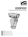
ULISSE PLUS
Positioning unit with large-sized camera housing
EN English - Instructions manual
IT Italiano - Manuale di istruzioni
FR Français - Manuel d'instructions
DE Deutsch - Bedienungslanleitung
ULISSE PLUS
Positioning unit with large-sized camera housing
EN English - Instructions manual
Contents
ENGLISH
1.1 Typographical conventions................................................................................................................................. 7
2 Notes on copyright and information on trademarks................................................. 7
3 Safety rules.................................................................................................................... 7
4 Identification................................................................................................................. 9
4.1 Product description and type designation.................................................................................................... 9
4.2 Product markings.................................................................................................................................................... 9
4.2.1 Checking the markings......................................................................................................................................................... 9
5 Versions........................................................................................................................ 10
5.1 Built-in Wiper..........................................................................................................................................................10
5.1.1 Washer.......................................................................................................................................................................................10
5.2 IP video encoder....................................................................................................................................................10
6 Preparing the product for use.................................................................................... 11
6.1 Safety precautions before use..........................................................................................................................11
6.2 Contents and unpacking....................................................................................................................................11
6.3 Safely disposing of packaging material........................................................................................................11
6.4 Preparatory work before installation.............................................................................................................12
6.4.1 Attaching the support.........................................................................................................................................................12
6.4.1.1 Attachment with bracket (optional)....................................................................................................................................................12
6.4.1.2 Attachment with a pole support (optional).....................................................................................................................................12
6.4.2 Cables management............................................................................................................................................................12
7 Assembling and installing.......................................................................................... 13
7.1 Assembly..................................................................................................................................................................13
7.1.1 Assembling the camera and motorised lenses..........................................................................................................13
7.1.1.1 Housing opening and camera installation........................................................................................................................................13
7.1.2 Connection of the camera and motorised lens..........................................................................................................14
7.1.2.1 Motorised lens PTZ board.......................................................................................................................................................................14
7.1.2.2 Connector for camera/motorised lenses...........................................................................................................................................14
7.1.2.3 Adjusting the power supply voltage of the lens motors.............................................................................................................15
7.2 Installation...............................................................................................................................................................16
7.2.1 Connecting the cables to the base.................................................................................................................................16
7.2.2 Fixing the base to the support.........................................................................................................................................17
7.2.3 Connection of the connector board..............................................................................................................................17
7.2.3.1 Connection of the power supply..........................................................................................................................................................17
7.2.3.2 Power supply connection 24Vac...........................................................................................................................................................18
7.2.3.3 Power supply connection 120/230Vac...............................................................................................................................................18
7.2.4 Video cable connection......................................................................................................................................................18
7.2.4.1 Telemetry line connections.....................................................................................................................................................................19
7.2.4.2 Alarm contact and relay connections.................................................................................................................................................19
7.2.5 Connecting the Ethernet cable (for IP board version only)...................................................................................20
7.3 Fixing the top unit.................................................................................................................................................20
7.4 Configuration..........................................................................................................................................................21
7.4.1 Dip-switch configuration...................................................................................................................................................21
7.4.2 Setting the baud rate...........................................................................................................................................................21
3
EN - English - Instructions manual
1 About this manual......................................................................................................... 7
EN - English - Instructions manual
7.4.3 Setting the protocol.............................................................................................................................................................21
7.4.4 Setting the address...............................................................................................................................................................22
7.4.5 Serial communication lines...............................................................................................................................................22
7.4.5.1 RS485 RX line...............................................................................................................................................................................................22
7.4.5.2 RS422 line (RS485-1 RX and RS485-2 TX)...........................................................................................................................................22
7.4.5.3 RS485-1 line reception, RS485-2 line repetition..............................................................................................................................23
7.4.5.4 RS485 TX/RX line.........................................................................................................................................................................................23
7.4.6 Serial terminations/connections.....................................................................................................................................23
8 Switching on................................................................................................................ 24
8.1 Before powering the device..............................................................................................................................24
8.2 Checks list.................................................................................................................................................................24
9 Configuration............................................................................................................... 25
9.1 On Screen Menu (OSM).......................................................................................................................................25
9.1.1 How to use the joystick.......................................................................................................................................................25
9.2 How to move around the menus.....................................................................................................................25
9.3 How to change the settings..............................................................................................................................26
9.4 How to change the numeric fields..................................................................................................................26
9.5 How to change text..............................................................................................................................................27
9.6 Configuring the system.......................................................................................................................................28
9.6.1 Main menu...............................................................................................................................................................................28
9.6.2 Language.................................................................................................................................................................................28
9.6.3 ZFI camera settings menu..................................................................................................................................................28
9.6.3.1 Zone titling menu......................................................................................................................................................................................28
9.6.3.2 Zone Masking Menu.................................................................................................................................................................................29
9.6.4 Housing Serial Port Menu..................................................................................................................................................30
9.6.5 Polarity Menu.........................................................................................................................................................................31
9.6.6 Movement menu...................................................................................................................................................................31
9.6.6.1 Manual Control Menu...............................................................................................................................................................................31
9.6.6.2 Manual Control Menu (Limits)...............................................................................................................................................................32
9.6.6.3 Preset Menu.................................................................................................................................................................................................32
9.6.6.4 Preset Menu (Edit Preset).........................................................................................................................................................................32
9.6.6.5 Preset Menu (Preset Utilities).................................................................................................................................................................33
9.6.6.6 Patrol Menu..................................................................................................................................................................................................33
9.6.6.7 Autopan Menu............................................................................................................................................................................................33
9.6.6.8 Motion Recall Menu..................................................................................................................................................................................34
9.6.7 Display menu..........................................................................................................................................................................34
9.6.8 Digital I/O Menu....................................................................................................................................................................35
9.6.8.1 Alarms menu................................................................................................................................................................................................35
9.6.8.2 Washer Menu...............................................................................................................................................................................................36
9.6.9 Default menu..........................................................................................................................................................................36
9.6.10 Info Menu..............................................................................................................................................................................36
9.7 IP Board Configuration........................................................................................................................................37
9.7.1 Minimum system requirements (version with IP Board only)...............................................................................37
9.7.2 Configuration procedure....................................................................................................................................................37
9.7.2.1 WAN setting..................................................................................................................................................................................................38
9.7.3 Installing the NVR software...............................................................................................................................................39
9.7.3.1 Controlling PTZ movements..................................................................................................................................................................41
9.7.3.2 Preset and load positions........................................................................................................................................................................42
10 Accessories................................................................................................................. 43
10.1 Washer....................................................................................................................................................................43
4
10.1.1 Connecting the pump......................................................................................................................................................43
10.1.1.1 Connection with a washer system in the UPTWAS/WASPT series.........................................................................................43
11.1 Visualizing the state of the pan & tilt...........................................................................................................44
11.2 Saving the current position (Preset).............................................................................................................44
11.3 Recalling a position (Scan)...............................................................................................................................44
11.4 Enabling Patrol function...................................................................................................................................44
11.5 Enabling Autopan Function............................................................................................................................44
11.6 Recalling the Home position..........................................................................................................................45
11.7 Enabling the Wiper (Wiper).............................................................................................................................45
11.8 Enabling the Washer (Washer).......................................................................................................................45
11.9 Reboot the device..............................................................................................................................................45
11.10 Special controls.................................................................................................................................................46
11.11 Special configurations....................................................................................................................................46
12 Maintaining and cleaning......................................................................................... 47
12.1 Maintaining...........................................................................................................................................................47
12.1.1 Replacing the fuses............................................................................................................................................................47
12.2 Cleaning.................................................................................................................................................................47
12.2.1 Window and plastic cover cleaning (PC)....................................................................................................................47
13 Disposal of waste materials...................................................................................... 47
14 Troubleshooting........................................................................................................ 48
15 Technical specifications............................................................................................ 50
15.1 General...................................................................................................................................................................50
15.2 Mechanical............................................................................................................................................................50
15.3 Electrical/video....................................................................................................................................................50
15.4 Communications.................................................................................................................................................50
15.5 Protocols................................................................................................................................................................50
15.6 Environment.........................................................................................................................................................50
15.7 Certifications.........................................................................................................................................................50
16 Technical drawings.................................................................................................... 51
17 Appendix A - Dip-switch address table................................................................... 52
5
EN - English - Instructions manual
11 Instructions for normal operation........................................................................... 44
6
EN - English - Instructions manual
3 Safety rules
Before installing and using this unit, please read this
manual carefully. Be sure to keep it handy for later
reference.
hh
1.1 Typographical conventions
DANGER!
High level hazard.
Risk of electric shock; disconnect the
power supply before proceeding with any
operation, unless indicated otherwise.
gg
DANGER!
Hot surface.
Avoid contact. Surfaces are hot and may
cause personal injury if touched.
ll
DANGER!
Mechanical hazard.
Risk of crushing or shearing.
ii
WARNING!
Medium level hazard.
This operation is very important for the
system to function properly. Please read
the procedure described very carefully and
carry it out as instructed.
hh
INFO
Description of system specifications.
We recommend reading this part carefully
in order to understand the subsequent
stages.
jj
The manufacturer declines all responsibility
for any damage caused by an improper use
of the appliances mentioned in this manual.
Furthermore, the manufacturer reserves
the right to modify its contents without any
prior notice. The documentation contained
in this manual has been collected with great
care, the manufacturer, however, cannot
take any liability for its use. The same thing
can be said for any person or company
involved in the creation and production of
this manual.
The integrated positioning systems for video
surveillance comprising the ULISSE line of devices
comply with current legislation and standards in force
at the time of publication of this handbook.
Nevertheless, in order to ensure the user’s safety
(installer technician and operator) the following
warnings are specified in order to work in maximum
safety:
If it is necessary to transport the device,
this should be done with great care. Abrupt
stops, bumps and violent impact could
damage the unit or injure the user.
hh
The building must be equipped with a
20A maximum bipolar protection circuit
(magneto thermal), that must include a
bipolar automatic-type circuit breaker,
which must also envisage earth fault
current protection (magneto-thermal +
differential) with minimum distance of
3mm between contacts.
hh
2 Notes on copyright and
information on trademarks
• The device must be installed only and exclusively
by qualified technical personnel.
The quoted names of products or companies are
trademarks or registered trademarks.
• Before any technical work on the appliance,
disconnect the power supply.
• Do not use power supply cables that seem worn
or old.
• Never, under any circumstances, make any
changes or connections that are not shown in
this handbook: improper use of the appliance
can cause serious hazards, risking the safety of
personnel and of the installation.
7
EN - English - Instructions manual
1 About this manual
EN - English - Instructions manual
• Use only original spare parts. Not original spare
parts could cause fire, electrical discharge or other
hazards.
• Before proceeding with installation check the
supplied material to make sure it corresponds
to the order specification by examining the
identification labels ("4.2 Product markings",
page 9).
• Connect the device to a power source
corresponding to the indications given on the
marking label. Before proceeding with installation
make sure that the power line is properly isolated.
For devices powered at 24Vac the supply voltage
should never exceed the (+/-10%) limit.
• Use a Class 2 listed UL tranformer, compliant with
the Standards in force, only for products marked
UL, powered at 24Vac.
• The device has been designed for permanent
installation in a building or other suitable structure.
• The device should be mounted so that it is
accessible only to the technician/installer because
the moving parts constitute a residual risk of injury
caused by movement of said parts.
• Attach the Dangerous Moving Parts (Fig. 05,
page 11) label near the device.
• Do not use the appliance in the presence of
inflammable substances.
• Do not allow children or unauthorised people to
use the appliance.
• The appliance should only be considered switched
off when the power supply has been disconnected
and the connecting cables to other devices have
been removed.
• Only skilled personnel should carry out
maintenance on the device. When carrying out
maintenance, the operator is exposed to the risk of
electrocution and other hazards.
• Use only the accessories indicated by the
manufacturer. Any change that has not been
expressly approved by the manufacturer will
invalidate the guarantee.
• Connect the coaxial cable to earth.
• Before connecting all the cables make sure the
device is properly connected to the earth circuit.
• If the device has to be removed from the
installation, always disconnect the earth cable last.
• Take all necessary precautions to prevent the
apparatus from being damaged by electrostatic
discharge.
8
• The unit has been made for connection using a
3-pole cable. To make a correct connection to
the earth circuit, follow the instructions in this
handbook.
• Before any technical work, always disconnect the
power supply; handle the device with great care:
high mechanical stress could damage the unit.
• Make especially sure that the power supply line is
isolated at a sufficient distance from all the other
cables, including lightning protection devices.
• The main switch must be easily accessible for rapid
intervention when needed.
• Installation category (also called Overvoltage
Category) specifies the level of mains voltage
surges that the equipment will be subjected to.
The category depends upon the location of the
equipment, and on any external surge protection
provided. Equipment in an industrial environment,
directly connected to major feeders/short branch
circuits, is subjected to Installation Category III. If
this is the case, a reduction to Installation Category
II is required. This can be achieved by use of an
isolating transformer with an earthed screen
between primary and secondary, or by fitting
listed Surge Protective Devices (SPDs) from live
to neutral and from neutral to earth. Listed SPDs
shall be designed for repeated limiting of transient
voltage surges, suitable rated for operating voltage
and designated as follows: Type 2 (Permanently
connected SPDs intended for installation on the
load side of the service equipment overcurrent
device); Nominal Discharge Current (In) 20kA min.
For example: FERRAZ SHAWMUT, STT2240SPG-CN,
STT2BL240SPG-CN rated 120/240Vac, (In=20kA).
4.2 Product markings
4.1 Product description and type
designation
On the pan & tilt devices have a label complying with
CE markings.
The ULISSE PLUS P&T integrates, in a particularly
elegant design, a high performance P&T head with
telemetry receiver and a bigger camera housing with
integrated wiper.
The rotation on the horizontal axis is continuous with
a variable speed up to 100°/s while the amplitude on
the vertical axis varies from +90° to -40° with a max
speed of 50°/s. ULISSE PLUS controls the functions of
autopan and patrol with a tracking accuracy of 0.02°
on preset positions upon recall. Patrol sequences can
also be varied with different speed settings in order
to customize a perfect patrol pattern.
This system is provided with incremental encoders for
position feedback which guarantee an exact position
control in any operating condition.
ULISSE PLUS is equipped with a thermostatically
controlled heater and sunshield, assuring an optimal
operating temperature.
In addition to the OSD set-up, the system is equipped
with an RS232 interface allowing the possibility to
update to the latest firmware version. The positioning
system is controlled through RS485/RS422. The
telemetry signal can be transmitted in an active way
for chain configuration of several ULISSE PLUS units
together.
The positioning unit can be used in several kinds
of installations, such as: coast and border patrol,
harbour control, urban settings, highway and traffic
monitoring, stadiums, industries, prisons or military
applications, and perimeter surveillance.
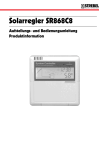
Fig. 01
The label on the body shows:
• Model identification code (Extended 3/9 bar code)
• Power supply voltage (Volt)
• Frequency (Hertz)
• Absorbed current (Amps)
• IP weatherproof standard
• Serial number
4.2.1 Checking the markings
Before proceeding further with installation, make
sure the material supplied corresponds to the order
specification by examining the marking labels.
Never, under any circumstances, make any changes
or connections that are not described in this
handbook: the use of inappropriate appliances may
expose personnel and the system to serious safety
hazards.
9
EN - English - Instructions manual
4 Identification
EN - English - Instructions manual
5 Versions
5.2 IP video encoder
5.1 Built-in Wiper
The pan & tilt can be fitted with a board for video
output through ethernet ("9.7 IP Board Configuration",
page 37).
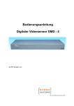
The pan & tilt can be fitted with a wiper.
Fig. 02
To operate the wiper, refer to "11.7 Enabling the Wiper
(Wiper)", page 45.
5.1.1 Washer
If the pan & tilt is fitted with a wiper, it can also have
an external pump supplying water to clean the glass.
As shown in the picture, the spray to clean the glass is
outside the pan & tilt.
Fig. 03
Once the command has been sent ("11.8 Enabling the
Washer (Washer)", page 45) the pan & tilt positions
itself with the glass facing the spray and the pump
and wiper are activated for a set period of time; at the
end of the operation the pan & tilt returns to its initial
position.
For models with Washer complete with level sensor,
the pan & tilt can also display a video message when
the level of the liquid inside the tank is too low (only
if using a high prevalence pump of the UPTWAS
series).
For further details on configuring and using
the Washer, refer to "9.6.8.2 Washer Menu",
page 36.
jj
10
Fig. 04
6 Preparing the product
for use
All other parts must not be disassembled
or tampered (excepting for mounting and
maintenance operations according the
present manual).
hh
6.1 Safety precautions before
use
In the 120/230Vac powered configuration
it is necessary to insert a 1 0 unipolar
main switch (open contact distance
d>3mm) upstream on the power line. This
switch should be used to disconnect the
power supply before carrying out any
maintenance operation or before opening
the housing.
gg
When the product is delivered, make sure that the
package is intact and that there are no signs that it
has been dropped or scratched.
EN - English - Instructions manual
Any change that is not expressly approved
by the manufacturer will invalidate the
guarantee.
hh
6.2 Contents and unpacking
If there are obvious signs of damage, contact the
supplier immediately.
Keep the packaging in case you need to send the
product for repairs.
Check the contents to make sure they correspond
with the list of materials as below:
• ULISSE PLUS positioning unit
• Accessories box:
• Allen key
• Sachet desiccant
• Attachment plate with screws
• Bolts and screws
• Serial extension cable
• Serial adapter
• Label
• Silicon sheath
• Ties
The appliance includes moving parts. Make
sure that the unit is positioned where it
is inaccessible under normal operating
conditions. Attach the warning label
supplied with the appliance, placing it near
the unit so that it can be seen easily.
hh
• Reduction gaskets for cable glands
• Instructions manual
• Power Supply Base Box:
• Power supply base
6.3 Safely disposing of
packaging material
The packaging material can all be recycled. The
installer technician will be responsible for separating
the material for disposal, and in any case for
compliance with the legislation in force where the
device is to be used.
Fig. 05
Bear in mind that if the material has to be returned
due to a fault, using the original packaging for its
transport is strongly recommended.
11
6.4.1.2 Attachment with a pole support
(optional)
6.4.1 Attaching the support
Use the wall UPTWBA or parapet UPTWBTA support.
Choose the most suitable one for your installation
and follow all the instructions given in this section.
The pole support allows the passage of the
connection cables. The base can be attached to the
pole in 4 distinct positions, turning through 90° to
each other, in order to facilitate positioning of the
configuration board.
The device should be assembled vertically.
Any other position could impair the
performance of the appliance. Do not
attach the device upside down.
hh
Take special care when attaching and
fastening down the apparatus. If it is to be
attached to a concrete surface you must
use dowel pins with a traction torque rating
of at least 300dN each; for a metal surface
use screws with a diameter of at least 8 mm
and of an appropriate length. However, the
clamping system must be able to support
at least 4 times the weight of the entire
equipment, including P&T, lenses and
camera.
Ø7
hh
Ø 101.6
Fig. 07
6.4.2 Cables management
The connection cables should not be
accessible from the outside; what is more,
since the cable could be pulled out it
is necessary to fasten it securely to the
pole in order to prevent excessive weight
pulling it out by accident and rendering the
apparatus unsafe.
hh
6.4.1.1 Attachment with bracket (optional)
The bracket is drilled to make it easy the connection
cables through it. The base can be attached to the
wall bracket in 4 distinct positions, turning through
90° to each other, in order to facilitate positioning of
the configuration board.
You must use cables suited to the type of
installation.
hh
Insert the cables into the support so that they
protrude by about 50cm.
50cm
150
EN - English - Instructions manual
6.4 Preparatory work before
installation
Ø9
110
Fig. 06
12
Fig. 08
50cm
7 Assembling and
installing
Take out the inner support slide (01) loosening the
fastening screws (02). Fix the camera, the optic and
the spacer (03) using the 1/4" screws supplied.
EN - English - Instructions manual
Only specialised personnel should be
allowed to assemble and install the device.
hh
7.1 Assembly
7.1.1 Assembling the camera and
motorised lenses
03
02
For some models of the P&T the customer has to take
care of assembling the camera and lenses.
The correct device working, in the stated
temperature range, is guaranteed with the
use of camera and lens with temperature
from -10°C up to +60°C.
hh
01
The camera output video signal must be of
the composite type with amplitude 1Vpp
(negative sync).
hh
7.1.1.1 Housing opening and camera
installation
To open the housing, undo the screws on the sides
and lift the upper body.
Fig. 10
Reposition the inner slide and tighten the screws that
had been loosened previously. Attach the essicant
bag using the bracket for this purpose.
Fig. 11
Fig. 09
On removing the upper section of the
housing, accompany it until the anchoring
cable is taut. Do not drop it as this could
cause the cable to snap.
hh
Close the housing after making the necessary
electrical connections.
It is necessary to insulate the camera body
from the attachment slide in order to
prevent interference with the video signal.
hh
13
EN - English - Instructions manual
7.1.2 Connection of the camera and
motorised lens
7.1.2.2 Connector for camera/motorised
lenses
7.1.2.1 Motorised lens PTZ board
hh
The following is a description of the electronics board
inside the housing, which controls all functions of the
motorised lens.
Code
Description
CN1
BNC connector for connecting the video signal
from the camera
CN2
Motorised lens motor control connector
CN3
Motorised lens potentiometer connector
CN6
Serial connector for controlling the camera
CN7
Camera power supply, clean contact for
activating the camera night mode, additional
lines
Tab. 01
CN6
CN7
CN1
CN3
CN2
All connections illustrated below should
be made only and exclusively by expert
installers who should comply with all the
wiring and power supply specifications for
the devices.
The electronics board is designed to control cameras
with motorised lenses (Focus, Iris, Zoom), which
may or may not have potentiometers to control the
position reached.
Before making the connections make sure that the
voltages supplied by the board fall within the limits
allowed for the apparatus.
Connector for camera/motorised lenses
Camera power supply
+12V - 800mA max
Lens potentiometer power
supply
+5V - 15mA max
Lens motor power supply
6-15V (adjustable) - 200mA
max (Focus+ Zoom+Iris)
Tab. 02
In the case of lenses with reverse polarity motors,
connect as shown in the following drawing:
M
Fig. 12
M
M
Fig. 13
+
+
+
FOCUS +
FOCUS IRIS +
IRIS ZOOM +
ZOOM -
CN2.
In the case of lenses with common wire motors,
enable the corresponding menu option ("9.6.3 ZFI
camera settings menu", page 28) and connect as
shown in the following drawing:
M
M
M
Fig. 14
14
CN2.
+
+
+
FOCUS +
FOCUS IRIS +
IRIS ZOOM +
ZOOM -
The potentiometer connections must be made as
shown in the following diagram.
Before powering the Pan & Tilt, set the lens power
voltage using DIP1.
IRIS
FOCUS
+ POT
FOCUS
IRIS
ZOOM
- POT
GND
EN - English - Instructions manual
ZOOM
7.1.2.3 Adjusting the power supply voltage
of the lens motors
CN3
DIP1
Fig. 15
Fig. 17
The camera connections must be made as shown in
the following diagram.
232 TX
232 RX
GND
485_B
485_A
S_GND
Serial
Lens power suppy voltage
DIP 1
DIP 2
OFF
OFF
Configuration
15Vdc
ON
OFF
12Vdc
OFF
ON
9Vdc
ON
ON
6Vdc
Tab. 03
CN6
Video
CN1
Night
synchronization
Power
supply
+ 12V
GND
F1
F2
CN1
Fig. 16
Refer to the relative chapter to enable camera control
("9.6.4 Housing Serial Port Menu", page 30)
15
7.2 Installation
EN - English - Instructions manual
7.2.1 Connecting the cables to the base
Do not make any changes or install
connections that are not included in this
handbook. Failure to follow the connection
instructions that are given in the handbook
may create serious safety hazards for
people and for the installation.
hh
Insert the cables into the cable glands and, holding
the base at about 20cm from the support, lock
the cable glands with a torque wrench setting of
5Nm. The cable glands are suitable for cables with
diameters of between 5 and 10mm.
Do not change the wiring in the product
as it is supplied to you. Failure to follow
this instruction may create serious safety
hazards for people and for the installation,
and will also invalidate the guarantee.
hh
If using the washer kit (UPTWAS), the
spray support should be installed before
positioning the pan & tilt and the wiring.
For further explanations see the specific
handbook for the kit.
jj
Fig. 19
For smaller cables (from 3 to 7mm) use the
supplied gaskets.
jj
Fig. 20
Fig. 18
Keep a connection diagram for future
reference.
jj
16
7.2.2 Fixing the base to the support
After having positioned gasket (01), fasten base (02)
on support (03) using screws (04), toothed spring
washers (05) and the rings for screw (06).
02
The following is a description of the connector board
located inside the P&T base.
03
01
Power
06
Signal
05
RS232
Fig. 24
04
7.2.3.1 Connection of the power supply
Fig. 21
The device is available in versions for different power
supply voltages: the value for the particular device
is shown on its identification label ("4.2 Product
markings", page 9).
02
01
03
06
05
04
Fig. 22
Align the 3 notches on the base with those on the
support as shown in the following figure.
Always make the base connections with the
power supply disconnected and the circuitbreaker open.
gg
When commencing installation make sure
that the specifications for the power supply
for the installation correspond with those
required by the device.
hh
Make sure that the power source and
connecting cables are suitable for the
power consumption of the system.
hh
The building must be equipped with a
20A maximum bipolar protection circuit
(magneto thermal), that must include a
bipolar automatic-type circuit breaker,
which must also envisage earth fault
current protection (magneto-thermal +
differential) with minimum distance of
3mm between contacts.
hh
Fig. 23
Apply a Loctite 243® type thread-locker on
the holes of the screws.
hh
Fasten with tightening
torque of 4Nm.
hh
17
EN - English - Instructions manual
To fasten the support use the specific bolts
and screws supplied with the base.
hh
7.2.3 Connection of the connector
board
Earth cable should be about 10mm longer
than the other two, so that it will not be
disconnected accidentally if the cable is
stretched or pulled.
EN - English - Instructions manual
hh
7.2.3.2 Power supply connection 24Vac
Connect the power supply cables as described in the
table below.
Power supply connection 24Vac
Colour
Terminals
Defined by the installer
(N) Neutral
Defined by the installer
(L) Phase
Yellow/Green
Earth
Tab. 04
a
Only for products marked UL intended for
the North American market, use a class 2 UL
listed transformer.
hh
Power
Fig. 25
The power supply cable should also be
covered by the silicone sheath (01) supplied
for this purpose, and fastened with the
corresponding tie (02). Furthermore, all
signal cables must be grouped together by
means of a strap (03).
hh
7.2.3.3 Power supply connection
120/230Vac
Connect the power supply cables as described in the
table below.
Power supply connection 120/230Vac
Colour
Terminals
Blue
(N) Neutral
Brown
(L) Phase
Yellow/Green
Earth
Tab. 05
Use the appropriate junction-box
UPTJBUL to connect the power supply
line. For further information, refer to the
product use and installation manual.
hh
01
02
03
Fig. 26
Cut the cables to the correct length and make the
connections. Connect the power supply to the J1
terminal.
7.2.4 Video cable connection
The installation is type CDS (Cable
Distribution System), do not connect it to
SELV circuits.
hh
In order to reduce the risk of fire, only
use cable sizes greater than or equal to
26AWG.
hh
Connect the screen and central cable
respectively to the GND and VIDEO
terminals. The terminals accept cables
with sections between 0.5 mm2 (AWG20)
and 0.08 mm2 (AWG28).
hh
N
Fig. 27
18
a L
Power
7.2.4.2 Alarm contact and relay connections
EN - English - Instructions manual
GND
VIDEO
Signal
Fig. 28
7.2.4.1 Telemetry line connections
The installation is type TNV-1, do not
connect it to SELV circuits.
hh
In order to reduce the risk of fire, only use
cable sizes greater than or equal to 26AWG.
hh
The product is supplied with 2 RS485 serial
communication lines and 1 RS232 serial line. These
can be configured in various ways according to the
positions of dip-switches 10 and 9 on the Serial and
Address selector ("7.4.5 Serial communication lines",
page 22).
A1
B1
A2
B2
+
V
Vdc
O1 C1
O2 C2
Signal
Fig. 31
Terminals
Description
F1-F2
Additional lines
O1-C1 and
O2-C2
Clean output contacts, can be activated by
alarm or by user control
AL1, AL2, AL3,
AL4 and COM
Live controlled alarm inputs referring to
common COM
Tab. 07
Signal
Fig. 29
Terminals
Description
A1-B1
Line RS485 (1)
A2-B2
Line RS485 (2)
Tab. 06
RS232
Fig. 30
19
EN - English - Instructions manual
7.2.5 Connecting the Ethernet cable
(for IP board version only)
To connect the net cable a UTP, Category 5E or
superior, 4 pair with a max length of 100m. is needed.
Telemetry transmission and video signal
pass through the Ethernet cable. Do not
connect cable RS485 and the video cable.
7.3 Fixing the top unit
Inside the bottom cover there is a sachet
containing desiccant that is used to prevent
moisture formation in the base and near
the connector boards. Remove the sachet
during installation.
jj
jj
Crimp the RJ45 connector on the ethernet cable.
Crimping should be straight-through if passing via
a hub or switch while it should be crossover if you
are connecting directly to the PC for the necessary
checks.
Connect the crimped net cable to connector RJ45
located on the base of the unit.
Attach the top unit (01) to the base (02) using
the attachment screws (03), supplied with the
corresponding seals (04). Make sure the base seal is
present and in good condition (05).
Fasten with tightening
torque of 4Nm.
hh
01
02
03
05
04
Fig. 32
Fig. 34
The example below shows a typical installation.
There is only one way to anchor the base
with the top part. Align the tabs on the
sides to make sure the parts are positioned
correctly.
jj
UTP cat 5E
Personal
Computer
Hub / Switch
UTP cat 5E
Fig. 35
Fig. 33
20
7.4 Configuration
Dip-switches 4, 3 and 2 are used to set the
communication rate of the device according to the
table below.
Dip-switch number 1 is used to update the firmware.
During normal use, make sure the rocker is OFF
(DIP1=OFF).
When the dip-switch rocker is up it
represents the value 1 (ON) while if it is
down it represents the value 0 (OFF).
jj
Baudrate setting
Fig. 36
7.4.1 Dip-switch configuration
Description
DIP DIP DIP DIP
4
3
2
1
Baudrate
adjustment
OFF OFF OFF
-
ON
OFF OFF
-
600 baud
OFF
ON
OFF
-
1200 baud
ON
The following diagram represents the position of
the dip-switches when the configuration window is
opened.
When the dip-switch rocker is up it
represents the value 1 (ON) while if it is
down it represents the value 0 (OFF). This
rule is valid for all dip-switches except for
in the section "7.4.6 Serial terminations/
connections", page 23 where they are
inverted.
jj
Rocker up = ON = 1
Rocker down = OFF = 0
Firmware update
Configuration
300 baud
ON
OFF
-
2400 baud
OFF OFF
ON
-
4800 baud
ON
OFF
ON
-
9600 baud
OFF
ON
ON
-
19200 baud
ON
ON
ON
-
38400 baud
-
-
-
ON
Set up enabled
-
-
-
OFF
Set up disabled
Tab. 08
7.4.3 Setting the protocol
Video positioning systems with the ULISSE line can be
controlled by a range of protocols.
When the dip-switch rocker is up it
represents the value 1 (ON) while if it is
down it represents the value 0 (OFF).
jj
Rocker up = OFF = 0
Rocker down = ON = 1
Fig. 37
Baudrate
Protocol Serial and Address
Protocol setting
DIP DIP DIP DIP DIP DIP DIP DIP
8
7
6
5
4
3
2
1
MACRO
(VIDEOTEC)
PANASONIC
RS232 serial
connector
ON
ON
OFF OFF OFF ON OFF ON
OFF OFF
PELCO D
OFF OFF OFF OFF ON
OFF OFF ON
AMERICAN
DYNAMICS
OFF OFF OFF OFF ON
ON
VISTA
Termination of
RS485 lines
OFF OFF OFF OFF OFF ON
OFF OFF OFF ON
ON
OFF
OFF OFF ON
ON
Tab. 09
Fig. 38
21
EN - English - Instructions manual
Before powering the device it must be configured
correctly by setting the dip-switches inside the
configuration window. Open the window by undoing
the screws as shown in the illustration:
7.4.2 Setting the baud rate
EN - English - Instructions manual
7.4.4 Setting the address
7.4.5.1 RS485 RX line
The ULISSE address can have a setting from 1 to 255.
Binary code is used to select the address, using the
8 dip-switches at the top right ("17 Appendix A - Dipswitch address table", page 52).
The line RS485-1 will operate according to the
settings in the Address, Baudrate and Protocol
dip-switch.
The RS485-2 serial line is not used.
7.4.5 Serial communication lines
The product is designed with two RS485 serial
communication lines and one RS232 serial line, which
can have various settings according to the positions
of dip-switches 10 and 9 on the Serial and Address
selector.
When the dip-switch rocker is up it
represents the value 1 (ON) while if it is
down it represents the value 0 (OFF).
jj
Serial And Address, Serial Line Configuration
DIP
10
DIP
9
DIP
8-1
Configuration
OFF OFF
-
It allows the one-way communication
on RS485-1 line ("7.4.5.1 RS485 RX line",
page 22).
OFF
-
It allows the full-duplex communication
according to RS422 standard ("7.4.5.2
RS422 line (RS485-1 RX and RS485-2 TX)",
page 22).
ON
ON
OFF
-
It allows the cascade configuration of
different devices. The signal is repeated
from every units ("7.4.5.3 RS485-1
line reception, RS485-2 line repetition",
page 23).
ON
ON
-
It allows the two-ways, half-duplex,
communication on RS485-1 line ("7.4.5.4
RS485 TX/RX line", page 23).
Control
Keyboard
RS485-1
RS232
Max 1200m
Personal
Computer
Max 10m
Fig. 39
The system is of the TNV-1 type, do not
connect it to SELV circuits.
hh
7.4.5.2 RS422 line (RS485-1 RX and RS485-2
TX)
This setting allows full duplex communication
according to the RS422 standard. This means that
both the RS485-1 and RS485-2 lines are used.
Control
Keyboard
RS485-1 RS485-2
Tab. 10
Max 1200m
Fig. 40
This function is only available for
bi-directional protocols (e.g. PELCO,
AMERICAN DYNAMICS, Macro, etc.).
jj
22
7.4.5.3 RS485-1 line reception, RS485-2 line
repetition
The diagram shows two dip-switches that are used to
configure termination of the serial line.
Every peripheral that is situated at the end of a line
must be terminated using the appropriate dip-switch
in order to prevent signal reflection and distortion.
dip-switches 1 and 2 terminate serial lines RS485-1
and RS485-2 respectively.
Unlike the previous cases in this table when
the dip-switch rocker is up it represents the
value 0 (OFF) while if the rocker is down it
represents the value 1 (ON).
jj
Control
Keyboard
RS485-1 RS485-2
RS485-1
Termination Of RS485 Lines
Description
Max 1200m
Max 1200m
Fig. 41
Line RS485-1
Line RS485-2
It only works with mono-directional
protocols.
jj
DIP 2 DIP 1
Configuration
-
ON
Terminated
-
OFF
Not terminated
ON
-
Terminated
OFF
-
Not terminated
Tab. 11
7.4.5.4 RS485 TX/RX line
With this type of setting it is possible to obtain a
bi-directional, half/duplex, communication on the
RS485-1 line.
The RS485-2 serial line is not used.
Control
keyboard
RS485-1
TX/RX
Max 1200m
Fig. 42
This function is only available for
bi-directional protocols (e.g. PELCO,
AMERICAN DYNAMICS, Macro, etc.).
jj
23
EN - English - Instructions manual
With this type of setting it is possible to connect more
than one device in cascade. The signal is repeated
from every unit, making it possible to markedly
increase total distance.
7.4.6 Serial terminations/connections
EN - English - Instructions manual
8 Switching on
Make sure that the ULISSE system and other
components of the installation are closed
so that it is impossible to come into contact
with live parts.
gg
Do not stay in the vicinity of the device
when it is powered. Always disconnect the
power supply before working on the device.
ii
Make sure that all parts are fastened down
firmly and safely.
hh
Systems in the ULISSE line are switched on by simply
connecting the power supply, and switched off by
disconnecting the power.
The automatic pre-heating (de-ice) process
could be started whenever the device is
switched on and the air temperature is
below 0°C. This process is used to ensure
that the device works properly even at low
temperatures; it lasts between 60 and 105
minutes depending on the model.
jj
8.1 Before powering the device
The first time the device is switched on we
recommend making sure it is configured correctly.
To do this, disconnect the power supply, remove the
dip-switch protection window and set the firmware
update dip-switch rocker to ON.
Power the device and after a few seconds it will be
possible to check the settings on the screen.
After completing the check, switch off the device
and re-toggle the firmware update dip-switch rocker
to the down position (number 1 in the baud rate
section).
Close the window and re-connect the power supply.
8.2 Checks list
While it is switching on, the device displays a list of
the checks it has to carry out before starting normal
operation.
STARTUP
-----------------------TEST FLASH
: OK
HOMING PROCEDURE
: OK
ZFI SEARCH
: OK
IO EXPANDER
:OFF
IR360 STATE
:OFF
Fig. 43
If one of the checks fails (ERR), seek
assistance. The message Off means that the
pan & tilt is not fitted with the described
option.
hh
24
9 Configuration
During normal ULISSE operation it is possible to
activate the On Screen Menu in order to set the
advanced functions using the corresponding key/s
(see the handbook for the keyboard you are using).
Exit the On Screen Menu with Zoom Wide (or
Zoom-).
9.1.1 How to use the joystick
All operations in the menus are carried out using the
joystick.
EN - English - Instructions manual
9.1 On Screen Menu (OSM)
9.2 How to move around the
menus
Each page of the OSM shows a list of parameters or
sub-menus that can be selected by the operator. To
scroll through the parameters move the cursor by
operating the joystick (up and down).
MANUAL CONTROL
-----------------------1 MAXIMUM SPEED : 20.00
2>VEL. WITH ZOOM :
N
3 TILT FACTOR
:
2
4 MOVEMENT LIMITS
>
Up
Left
Right
Fig. 46
The symbol > at the end of a line indicates the
presence of a specific submenu. To enter the
submenu just confirm the menu item. To exit the
submenu use the Exit funcjtion (Zoom Out).
Down
Fig. 44
Pan & tilt.
Exit
Fig. 45
Confirm
Zoom wide & tele.
MANUAL CONTROL
-----------------------1 MAXIMUM SPEED : 20.00
2>VEL. WITH ZOOM :
N
3 TILT FACTOR
:
2
4 MOVEMENT LIMITS
>
Fig. 47
If using a control keyboard with a dual axis
joystick, use the Zoom Wide and Zoom
Tele keys to carry out the Exit and Confirm
commands.
jj
25
EN - English - Instructions manual
9.3 How to change the settings
Move the cursor to the parameter to be changed and
confirm. The field will start flashing, indicating that
it is in change mode. Operating the joystick (up and
down) will show the alternative choices.
MANUAL CONTROL
-----------------------1 MAXIMUM SPEED : 20.00
2>VEL. WITH ZOOM :
N
3 TILT FACTOR
:
2
4 MOVEMENT LIMITS
>
9.4 How to change the numeric
fields
Move the cursor to the parameter to be changed,
then confirm.
EDIT PRESET
-----------------------1 NR. :
1
2 ENAB.:
N
3>PAN : + 0.00
4 TILT : - 40.00
5 SPEED:
20.00
6 PAUSE:
5
7 TEXT : PRESET 001
8 GO TO PRESET?
Fig. 50
Fig. 48
After identifying the desired selection, confirm.
MANUAL CONTROL
-----------------------1 MAXIMUM SPEED : 20.00
2>VEL. WITH ZOOM :
N
3 TILT FACTOR
:
2
4 MOVEMENT LIMITS
>
Fig. 49
The parameter will stop flashing to confirm the
choice.
The first digit in the numeric field to be changed will
flash and the last line of the display will show the
accepted limits for the field. Move in the field (left
and right) and change the sign or the numeric value
(up and down).
EDIT PRESET
-----------------------1 NR. :
1
2 ENAB.:
N
3>PAN : +000.00
4 TILT : - 40.00
5 SPEED:
20.00
6 PAUSE:
5
7 TEXT : PRESET 001
8 GO TO PRESET?
min:-180.00 max:+179.99
Fig. 51
After making the change, confirm. The cursor returns
to the left and the modified figure stops flashing.
The field will be forced to the minimum or maximum
allowed value if you try to insert a value outside the
limits.
26
9.5 How to change text
EDIT TEXT: AREA
-----------------------Text: TEXT AREA1
↑
>A B C D E F G
ERASE
H I J K L M N
SAVE
O P Q R S T U
EXIT
V W X Y Z 0 1
abc
2 3 4 5 6 7 8
9 : . , ? ! &
+ - * / =
SPACE ← →
EDIT ZONE
-----------------------1 NR. :
1
2 START:+ 0.00
3 STOP :+ 0.00
4>TEXT :TXT AREA1
EN - English - Instructions manual
Move the cursor to the parameter to be changed,
then confirm.
Press Enter (Zoom Tele) to enter the required
character.
Fig. 55
Fig. 52
The text editing screen will appear.
Symbol ↑ will position itself under the character that
can be edited while the cursor > positions itself to the
right of the character to be entered.
EDIT TEXT: AREA
-----------------------Text: TEXT AREA1
↑
>A B C D E F G
ERASE
H I J K L M N
SAVE
O P Q R S T U
EXIT
V W X Y Z 0 1
abc
2 3 4 5 6 7 8
9 : . , ? ! &
+ - * / =
SPACE ← →
Use:
• ERASE: To delete the whole text string.
• SAVE: To store the new text.
• EXIT: To exit the menu.
• abc: To display lower case letters.
EDIT TEXT: AREA
-----------------------Text: TEXT AREA1
↑
>A B C D E F G
ERASE
H I J K L M N
SAVE
O P Q R S T U
EXIT
V W X Y Z 0 1
abc
2 3 4 5 6 7 8
9 : . , ? ! &
+ - * / =
SPACE ← →
Fig. 53
Fig. 56
You can move inside the menu using the joystick.
To exit the menu you can also use the Zoom Wide
key.
EDIT TEXT: AREA
-----------------------Text: TEXT AREA1
↑
>A B C D E F G
ERASE
H I J K L M N
SAVE
O P Q R S T U
EXIT
V W X Y Z 0 1
abc
2 3 4 5 6 7 8
9 : . , ? ! &
+ - * / =
SPACE ← →
Fig. 54
27
EN - English - Instructions manual
9.6 Configuring the system
9.6.3 ZFI camera settings menu
9.6.1 Main menu
01. Zoom: This sets the maximum zoom level that
the motorised lens can achieve.
From the main menu it is possible to enter menus for
configuring the device.
MAIN MENU
-----------------------1>LANGUAGE
>
2 ZFI LENSES
>
4
5
6
7
8
MOTION
DISPLAY SETUP
DIGITAL I/O
DEFAULT
INFO
>
>
>
>
>
Fig. 57
This is a dynamic self-configuration menu based on
the Pan & Tilt model.
9.6.2 Language
This menu is used to select and set the desired
language.
LANGUAGE MENU
-----------------------1 ITALIANO
2>ENGLISH
OK
3 FRANCAIS
4 DEUTSCH
02. Common Wire: If enabled, it manages the
motorised common wire lenses; if disabled, it
manages those with inversed polarity.
04. Area Titling: Allows access to the area titling
submenu.
05. Zone Masking: This provides access to the zone
masking management submenu.
06. Housing Serial Port: Allows access to the
submenu for managing the housing serial port.
07. Polarity: Allows access to the submenu for
managing the polarity of the Zoom, Focus and
Iris motors.
ZFI CAMERA SETTINGS
-----------------------1>ZOOM
:
30x
2 COMMON WIRE
:
N
4
5
6
7
ZONE TITLING
ZONE MASKING
HOUSING SERIAL PORT
POLARITY
>
>
>
>
Fig. 59
9.6.3.1 Zone titling menu
This function allows setting up to 8 areas (variable
dimension) with titling option.
From the Zone Titling menu it is possible to set the
following parameters:
01. Number: Selects the area to be edited.
Fig. 58
02. Enabling: Enables the message linked to the
related zone to be displayed on the screen.
03. Start: Sets the initial position of the area.
04. Stop: sets the final position of the area.
28
05. Text: Modifies the text which is displayed when
moving within the zone.
Fig. 60
Example: To enable titling of zone 1 when the device
is between +15° and +45°, it is necessary to:
This function allows setting up to eight masks
(variable dimension) with titling option.
01. Number: Selects the mask to modify.
02. Enabling: Enables masking of the relative zone.
03. Start: Sets the starting position of the mask.
04. Stop: Sets the stop position of the mask.
05. Text: Changes the text displayed when the mask
is enabled.
ZONE MASKING
-----------------------1>NR
:
1
2 ENAB.:
N
3 START: + 0.00
4 STOP : + 0.00
5 TEXT : MASK 1
• Enable area titling by setting Y as the value of
Enabling.
• Set 1 as the value of parameter Nr.
• Set +015.00 as the value of parameter Start.
• Set +045.00 as the value of parameter Stop.
• If necessary, edit the displayed text by selecting
Text.
Fig. 62
Setting the Start and Stop values of the
menu to zero will disable text display. If
there are overlapping areas, the area with
the lowest number will prevail.
jj
To define zones proceed in a clockwise
direction, as shown in the figure.
jj
Stop2=225°
Start1=15°
270°
0°
180°
Stop1=45°
90°
Start2=170°
Fig. 61
29
EN - English - Instructions manual
ZONE TITLING
-----------------------1>NR. :
1
2 ENAB.:
N
3 START: + 0.00
4 STOP : + 0.00
5 TEXT : ZONE 1
9.6.3.2 Zone Masking Menu
EN - English - Instructions manual
Example: To enable masking of zone 1 when the
device is in the +15° and +45° position, proceed as
follows:
• Set the Nr parameter value to 1.
• Enable zone masking by setting the Enabling
value to Y.
• Set the Start parameter value to +015.00.
9.6.4 Housing Serial Port Menu
Once you have exited from the camera
OSM, press the IRIS CLOSE key to return to
the Pan & Tilt OSM.
jj
To prevent the camera OSM from
overlapping the Pan & Tilt OSM, exit from
the camera configuration mode before
pressing the IRIS CLOSE key.
jj
• Set the Stop parameter value to +045.00.
• Change the displayed text by selecting the Text
option, where required.
Set the Start and Stop menu values to zero
to disable the masking option. If a number
of masks are superimposed, the mask with
the lowest number will prevail over the
others.
jj
To define the masks, proceed in a clockwise
direction as seen in the diagram.
jj
01. Protocol: Allows the setting of the protocol
used for the serial communication with the
camera.
02. Baud Rate: Allows the setting of the baud rate
used for the serial communication with the
camera.
03. Return Cmd: Allows the personalization of
the Confirm command ("9.1.1 How to use the
joystick", page 25) for navigating inside the
camera OSM.
04. Exit Cmd: Allows the personalization of the
Exit command ("9.1.1 How to use the joystick",
page 25) for navigating inside the camera
OSM.
Stop2=225°
270°
180°
Start2=170°
Start1=15°
05. Enable Camera OSM: Allows access to the
camera configuration mode.
0°
Stop1=45°
90°
HOUSING SERIAL PORT
-----------------------1>PROTOCOL :
NONE
2 BAUDRATE :
9600
3 RETURN CMD: IRIS CLOSE
4 EXIT CMD : IRIS OPEN
5 ENABLE CAMERA OSM
>
Fig. 63
Fig. 64
30
9.6.5 Polarity Menu
01. Zoom: Allows the setting of the rotation polarity
of the lens Zoom motor.
02. Focus: Allows the setting of the rotation polarity
of the lens Focus motor.
03. Iris: Allows the setting of the rotation polarity of
the lens Iris motor.
POLARITY
-----------------------1>ZOOM :
POSITIVE
2 FOCUS:
POSITIVE
3 IRIS :
POSITIVE
06. Motions Recall: To access the submenu which
manages automatic load of the movements.
MOTION
-----------------------1>OFFSET PAN:
+ 20.00
2 MANUAL CONTROL
>
3 PRESET
>
4 PATROL
>
5 AUTOPAN
>
6 MOTIONS RECALL
>
EN - English - Instructions manual
The following parameters can be set from the Polarity
menu:
Fig. 66
9.6.6.1 Manual Control Menu
01. Maximum Speed: Sets the maximum manual
speed.
02. Speed With Zoom: When enabled, this
parameter automatically slows down the PAN &
TILT speed, based on the ZOOM factor.
Fig. 65
9.6.6 Movement menu
01. Offset Pan: The pan & tilt has a mechanically
defined 0° position. The Offset Pan function
allows the definition of a different 0° position
using software.
02. Manual Control: To access the submenus
operating the parameters associated with the
manual movements of the device.
03. Tilt factor: Sets the reduction factor of the tilt
axis manual speed.
04. Movement Limits: To access the Limits menu
MANUAL CONTROL
-----------------------1>MAXIMUM SPEED : 20.00
2 VEL. WITH ZOOM :
N
3 TILT FACTOR
:
2
4 MOVEMENT LIMITS
>
03. Preset: To access the submenus used to to edit
Preset values.
04. Patrol: To access the submenus used to edit
Patrol values.
05. Autopan: To access the submenus used to edit
Autopan values.
Fig. 67
31
EN - English - Instructions manual
9.6.6.2 Manual Control Menu (Limits)
9.6.6.4 Preset Menu (Edit Preset)
Once inside the Limits menu it is possible to set the
following parameters:
Once inside the Edit Preset menu it is possible to set
the following parameters:
01. Pan Limits: Enables the limits of Pan.
01. Number: The Preset number to be edited.
02. Pan Start: Sets the start limit of Pan.
02. Enabling: Enabling preset.
03. Pan End: Sets the end limit of Pan.
03. Pan: Pan position in degrees.
04. Tilt Start: Sets the start limit of Tilt.
04. Tilt: Tilt position in degrees.
05. Tilt End: Sets the end limit of Tilt.
05. Speed: The speed at which the position is
reached when preset is recalled from the Patrol
and Scan function.
LIMITS
-----------------------1>PAN LIMITS :
N
2 PAN START
: + 0.00
3 PAN END
: + 0.00
4 TILT START : + 0.00
5 TILT END
: + 0.00
06. Pause: Sets the dwell time in seconds before
starting the next movement in Patrol.
07. Text: The text that is displayed when the preset
position is reached.
08. Go To Preset: Obliges the Pan & Tilt to move to
the selected Preset position.
09. Enable Movements: Allows the Pan & Tilt to
shoot new Preset positions.
Fig. 68
This is a dynamic self-configuration menu based on
che choice made and displays the parameters on
which it is possibile to operate.
9.6.6.3 Preset Menu
01. Edit Preset: Allows access to Edit Preset menu.
02. Utilities Configuration: Allows access to
Utilities Configuration menu
PRESET
-----------------------1>EDIT PRESET
>
2 PRESET UTILITIES
>
Fig. 69
32
EDIT PRESET
-----------------------1>NR. :
1
2 ENAB.:
N
3 PAN : + 0.00
4 TILT : - 40.00
5 SPEED:
20.00
6 PAUSE:
5
7 TEXT : PRESET 001
8 GO TO PRESET?
9 ENABLE MOVEMENTS
>
Fig. 70
From the menu it is possible to directly store the
preset by sending the Iris Close command that
enables the pan & tilt movements.
9.6.6.6 Patrol Menu
Once inside the Utilities Configuration menu it is
possible to set the following parameters:
01. First Preset: Sets the first preset of the Patrol
sequence.
01. Scan Speed: This is the reference speed used
when a preset position is recalled by the Scan
function.
02. Last Preset: Sets the last preset of the Patrol
sequence.
02. Default Speed: Changes the default speed
of the Presets. This value is used based on the
function Set Speed? to assign the same speed
to all Presets .
03. Default Dwell time: Changes the default pause
of the Presets. This value is used based on the
function Set Dwell Time? to assign all Presets
the same pause time.
03. Random Mode: Enables random execution. The
sequence is re-calculated on a continuous basis.
PATROL
-----------------------1>FIRST PRESET :
1
2 LAST PRESET
: 250
3 RANDOM MODE
:
N
04. Ramp Value: The Ramp parameter is used
to change start and stop times. The higher
the number, the greater the acceleration/
deceleration during starting/stopping.
05. Set Speed?: To assign all Presets the same
default speed.
06. Set Dwell Time?: To assign all Presets the same
default dwell time.
PRESET UTILITIES
-----------------------1>SCAN SPEED
: 20.00
2 DEFAULT SPEED : 10.00
3 DEFAULT DWELL :
3
4 RAMP VALUE
:
12
5 SET SPEED?
6 SET DWELL TIME?
Fig. 72
9.6.6.7 Autopan Menu
01. Preset Outward Movement: Sets the initial
position of the Autopan.
02. Preset Return Movement: Sets the final
position of the Autopan.
AUTOPAN
-----------------------1>PRESET OUTWARD:
1
2 PRESET RETURN :
2
Fig. 71
Fig. 73
The movement speed is specified inside the
Preset ("9.6.6.4 Preset Menu (Edit Preset)",
page 32).
jj
33
EN - English - Instructions manual
9.6.6.5 Preset Menu (Preset Utilities)
EN - English - Instructions manual
9.6.6.8 Motion Recall Menu
9.6.7 Display menu
It is possibile to set the P&T so that, after a given
inactivity interval, it automatically carries out the
movement function set by the operator.
01. Actual Position: If not on Off, it is used to select
how the Pan, Tilt, Zoom, Focus and Iris positions
are displayed on the screen.
From the menu it is possible to set the following
parameters:
02. Preset Name: If not on Off, it is used to select
how the text associated with the last-reached
Preset position is displayed on the screen. It is
possibile to select timed (1 S, 3 S and 5 S) or a
constant (Const) display.
01. Movement Type: Choice of type of movement
to be loaded (None, Home, Autopan, Patrol).
02. Movement Delay: The time (in seconds) that
needs to elapse from the state of inactivity of
the Joystick before loading the set movement.
MOTION RECALL
-----------------------1>MOVEMENT TYPE :
NONE
2 MOVEMENT DELAY:
60
03. Pan & Tilt ID: If not on Off, it shows the ID of the
pan & tilt.
04. Alarms: When not switched to Off, this selects
the view mode for alarm related texts. It is
possible to select a timed view mode (1 S, 3 S
and 5 S) or constant view mode (Const).
05. Received Commands: If enabled, it shows the
received serial commands.
06. Horizontal Delta: Modifies the horizontal
position of the menu texts.
07. Vertical Delta: Modifies the vertical position of
the menu texts.
08. Video Signal: Type of video signal.
Fig. 74
DISPLAY
-----------------------1 ACTUAL POSITION :
ON
2 PRESET NAME
: 5 S
3 UNIT ID
:
ON
4 ALARMS
:
ON
5 RECEIVED COMMAND:
ON
6 HORIZONTAL DELTA:
35
7 VERTICAL DELTA :
10
8 VIDEO SIGNAL
: PAL
Fig. 75
This is a dynamic self-configuration menu based on
the Pan & Tilt model.
34
9.6.8 Digital I/O Menu
01. Alarms: Allows access to the Alarms menu.
DIGITAL I/O
-----------------------1>ALARMS
>
2 WASHER
>
01. Type: Set the type of contact: normally closed
(N.C.) or normally open (N.O.).
02. Action: The type of action (Off, Msg, Ptz Stop,
Wiper, Washer, Scan, Patrol, Autopan, Relay,
Ir Filt) carried out by P&T when the alarm
triggers. If Off is selected, the alarm is disabled.
03. Number: The preset to be reached when the
alarm’s type of action is Scan.
04. Text: The message that is displayed when the
alarm is active.
Fig. 76
9.6.8.1 Alarms menu
01-04. Alarms 1-4: Allow access to the menus from
which it is possible to set the parameters of
Alarms 1 to 4.
ALARM 1
-----------------------1>TYPE :
N.C.
2 ACT. :
SCAN
3 NR. :
1
4 TEXT : ALARM 1
Alarms State: Allows access to the Alarms
State menu.
05.
ALARMS
-----------------------1>ALARM 1
>
2 ALARM 2
>
3 ALARM 3
>
4 ALARM 4
>
5 ALARMS STATE
>
Fig. 77
This is a dynamic self-configuration menu based on
the Pan & Tilt model.
Fig. 78
This is a dynamic self-configuration menu based on
the choice made and shows the parameters on which
it is possible to operate.
From the Alarms menu it is possible to access the
Alarms State menu where the state of alarms inputs
is displayed (Closed, contact closed, Open, contact
open).
ALARMS STATE
-----------------------ALARM 1
CLOSED
ALARM 2
OPEN
ALARM 3
CLOSED
ALARM 4
CLOSED
From the Alarms menu it is possible to access one of
the menus (Alarms 1-4) to edit the alarms parameters.
Fig. 79
35
EN - English - Instructions manual
02. Washer: Allows access to the Washer menu.
From these menus it is possible to set the following
values:
EN - English - Instructions manual
9.6.8.2 Washer Menu
9.6.9 Default menu
The P&T offers the possibility to use a wiper and to
operate a pump to clean the glass.
01. Delete Setup: Resets all the parameters except
the Presets.
To configure the Washer put the lens of the camera in
front of the nozzle of the Washer.
02. Delete Preset: Deletes all previously stored
presets.
Save a preset (XY) that identifies this position; the
preset will be recalled by the pan & tilt when the
WASHER function is enabled.
From the menu, set the following parameters:
01. Enable: Enables the Washer function.
DEFAULT
-----------------------1>DELETE SETUP?
2 DELETE PRESET?
02. Nozzle preset: Enter the preset number (XY)
corresponding to the nozzle.
03. Wiper On Delay: Sets the interval between the
enabling of the pump and that of the wiper.
04. Washing length: Sets the length of the
brushing.
05. Wiper Off Delay: Sets the length of the
brushing without water.
WASHER
-----------------------1 ENABLE
: N
2 NOZZLE PRESET
: 1
3 WIPER-ON DELAY
: 5
4 WASHING DURATION : 10
5 WIPER-OFF DELAY
: 5
Fig. 80
Fig. 81
The above mentioned operations cause the
loss of all previously stored data (i.g. Preset,
Patrol, Autopan, Home…).
hh
9.6.10 Info Menu
The menu is used to check the configuration of the
device and the installed firmware version.
INFO
-----------------------Device ID: 00001
Type
: Rs485 only Rx
Baud Rate: 38400-8N1
Protocol : MACRO
Net Board: Fw05.07 Hw01
Mpp Board: Fw05.07 Hw00
Config.
: 001
P.C.
: UPT1SVSA000E
S.N.
: 000000000000
Upgrade : NET BOARD
Fig. 82
36
Enter address 192.168.0.100. you will have to log in
with a password.
9.7.1 Minimum system requirements
(version with IP Board only)
The default account name is: Admin
(with a capital A).
Choose one of the following configurations,
according to the number of channels to be controlled
The default password is: 123456
CHANNELS
Cpu
Mem
HDD
16
Intel Core 2
Duo 2.4 GHz
1GB
250GB
32
Intel Core
2 Duo 2.66
GHz
2GB
250GB
49
Intel Core 2
Quad 2.66
GHz
4GB
250GB
64
Intel Core 2
Quad 2.66
GHz
4GB
250GB
Tab. 12
9.7.2 Configuration procedure
When making the settings for the first time, insert the
default account name and password.
Fig. 83
When installing for the first time, it will be necessary
to install OCX control in order to have a correct video
display and then confirm the settings in the following
pop-up menu.
Once the pan & tilt has been preset and configured
("7.2.5 Connecting the Ethernet cable (for IP board
version only)", page 20) start configuring the IP
parameters of the pan & tilt.
The IP address of the various units should be
configured using a PC with a Microsoft Windows Xp®
service pack 2 or Microsoft Windows Vista® (Business
Edition or Enterprise Edition) OS and Microsoft
Internet Explorer® software.
Set the IP address of the PC as 192.168.0.1 (or
192.168.0.2 etc.).
To configure the unit, connect it physically to the
LAN, power it and run the browser Microsoft Internet
Explorer® version 6.0 or above.
To set the IP address of the various units,
power them, taking care to connect them
one at a time to the LAN (switch/hub).
Configure the unit and insert the settings
for at least the IP address and host name.
When the unit has all the desired settings,
connect the ethernet cable and go on to
configure the next unit.
jj
Fig. 84
When you have pressed OK/Enter in the pop-up
menu, the following window will appear.
Fig. 85
37
EN - English - Instructions manual
9.7 IP Board Configuration
9.7.2.1 WAN setting
The Live Video window will then appear.
Next, set the static IP address, which is used to
gain access to the unit that is to be configured. For
example, set a static IP and address 192.168.0.101.
EN - English - Instructions manual
Continue by pressing the Install button.
Fig. 86
To make the parameter settings, click on the Quit
button next to the video display. The general
parameter setting menu will then appear.
Fig. 88
Next, click on Apply and then click on Save &
Reboot. Wait about 30 seconds, until the settings
have been saved. Re-connect to the modified address
(e.g. 192.168.0.101), inserting the Account Name and
Password (use the default settings if they have not
been changed).
Then edit the other parameters, for example:
• Date Setting: To set date and time.
Fig. 87
38
• Video Setting: To change resolution (720x576,
640x480, 352x288, 176x144) bit rate (setting
between 28kbit and 3 Mbit).
For telemetry, leave the default settings.
9.7.3 Installing the NVR software
Insert the CD-ROM in the player, and after a few
seconds the following introductory display will
appear.
Fig. 89
After all the settings have been inserted, remember
to Save & Reboot, so that the changes will take
effect.
• Factory Default: Used to restore default factory
settings.
In extreme cases, when you have forgotten
the password for accessing the unit via the
browser, you can also restore the factory
settings by pressing a Reset button situated
inside the base.
hh
RESET button
Fig. 91
Select Videotec NVR Professional and follow the
instructions that appear on the screen.
When you have completed installation, and the pan
& tilts have been configured as appropriate (see
previous section), you can run the NVR software to
make the initial settings for the system.
Start the Activemonitor software.
You will have to insert the usual User Name (default:
Admin) and Password (default: 123456)
Fig. 90
For Reset to take effect, you have to disconnect the
power supply to the pan & tilt and then press the
reset button, and keep it pressed while reconnecting
the power supply.
Keep the button pressed for 5 seconds.and then
release it.
The factory default values of the unit are restored.
39
EN - English - Instructions manual
A CD-ROM containing display and control software is
supplied for controlling the various units. Follow the
instructions below to install the software correctly.
EN - English - Instructions manual
The first time you run the program, the following
display will appear, with an empty camera list
(Camera Tree).
Camera tree
When setting up manually, it is essential (as in
automatic setup, apart from the IP address) to set the
items marked by an asterisk, i.e.
Camera ID: Consecutively, 1, 2, 3 etc.
Tool bar
Camera IP: E.g. 192.168.0.102
Camera Model: Select 1-CH Video Server
Fig. 95
Set the name that will appear in the Camera Tree:
Camera Name: E.g. ULISSE 2
On completion, click on Apply and wait until the
settings have been saved.
Manual control
Video Live
Fig. 92
At this point you need to add the various devices
present in the system. Click on the Setup button in
the control bar.
Repeat the procedure for all the other devices
present in the system.
On completion of this stage, you should
close the NVR program and re-start it so
that the changes take effect. When the
program is restarted, the Camera Tree
should contain a list of the units in the
system for which settings have been made.
hh
Setup button
Fig. 93
From the Media Source list, drag & drop the first
unit into one of the blue windows, and the live video
image should appear.
Then click on Setup Camera.
Fig. 94
Insert the settings manually if you know the IP
addresses of the various units present, otherwise do
an automatic setup, which will identify the various
units.
40
Fig. 96
Example of drag & drop.
Repeat the procedure for the other units.
9.7.3.1 Controlling PTZ movements
To set movement control via the control panel or via
mouse, proceed as follows:
Select the first unit, or the one you want to configure,
from the Media Source list. Check the Enable PTZ
box. Then click on Apply. This will automatically set
the Videotec Macro protocol at 38400 baud.
Fig. 97
Repeat the procedure for the other units to be
controlled, directly from the PTZ setup menu (see
illustration above); just select the other units present
in the Media Source list of the Camera Tree menu,
one at a time, and check Enable PTZ, then click on
Apply.
Mouse PTZ
Fig. 99
To set the configuration parameters of the pan & tilt
by means of OSM, enable the corresponding function
using the control panel.
When the unit settings have been inserted,
quit the NVR programm and re-start it so
that all the changes will be saved.
hh
To control a unit via the control panel, select the unit
to be controlled by clicking with the mouse on the
corresponding video window, and then operate from
the control panel .
OSD
Fig. 100
Fig. 98
41
EN - English - Instructions manual
Select the Setup / Setup Camera menu and select
the PTZ tab.
It is possible to set 5 different speeds for pan and tilt
and it is also possible to enable advanced functions
using the Action menu (which contains, for example,
the Autopan, Start, Stop commands etc.). If you
want to control the PTZ using the mouse, directly
from the video window, check Mouse PTZ in the
control panel. You can then use the mouse to control
both movements and zoom (Zoom + and - are
situated in the centre).
EN - English - Instructions manual
To move around within the menu use the up and
down arrow keys, and confirm using the Enter key.
The Leave key is used to quit the submenu/menu.
For a complete description of the functions
that can be set via OSM see "9.6 Configuring
the system", page 28.
jj
9.7.3.2 Preset and load positions
Before making these settings, we
recommend enabling Mouse PTZ control,
so that it is easier to move around in the
position to be saved.
jj
Set the preset positions for the other units in the
same way.
Close the NVR application and re-start it to
save the settings.
hh
When the application is re-started, the preset
positions can be loaded using the Go To command
on the control panel, and selecting the desired
position.
Enter the Setup / Setup Camera Menu and select
the PTZ Preset tab.
Select the desired unit from the Media Source list
(e.g. ULISSE 3) and enable the Live View function.
Fig. 102
To control the other available functions, such as
recording on disc, playback and snapshot, and for
other detailed information about using the software,
see the manual on the installation CD: NVR User
Manual.
Fig. 101
Move to the desired position using Mouse control on
the video window.
Edit one of the boxes for the various preset positions
(Enter some text, such as Position No.2) and then
confirm by clicking on the blue button at the side.
Enter other preset positions as required.
On completion, click on Apply.
hh
42
10.1.1 Connecting the pump
10.1 Washer
hh
If the pan & tilt is fitted with a wiper, it can also have
an external pump supplying water to clean the glass.
As shown in the picture, the spray to clean the glass is
outside the pan & tilt.
The connections illustrated below should
be made only and exclusively by skilled
operatives who should comply scrupulously
with all the wiring and power supply
instructions. Failure to do so could create
serious risks for the operator and would
invalidate the guarantee.
O1
C1
AL1
COM
Signal
Fig. 103
Once the command has been sent ("11.8 Enabling the
Washer (Washer)", page 45) the pan & tilt positions
itself with the glass facing the spray and the pump
and wiper are activated for a set period of time.
At the end of the operation the P&T returns to its
initial position.
Fig. 104 Signal connector on the base board of the pan & tilt.
All models in the ULISSE series have this function.
The diagram shows:
• AL1 - COM: Alarm input, to monitor the presence
of water in the tank. For devices with level sensors,
closure of the contact, if enabled, generates an
appropriately configured on screen alarm.
• O1 - C1: Clean contact for starting the water pump.
10.1.1.1 Connection with a washer system in
the UPTWAS/WASPT series
For the connections see the product installation
handbook. Some models may not have a washer
liquid level sensor.
43
EN - English - Instructions manual
10 Accessories
EN - English - Instructions manual
11 Instructions for normal
operation
11.1 Visualizing the state of the
pan & tilt
During normal operation the pan & tilt displays
on screen the data organized as illustrated (user’s
choice). Visualization can be enabled or disabled as
described in "9.6.7 Display menu", page 34.
11.2 Saving the current position
(Preset)
The current position can be saved using the control
device being used (for additional information refer to
the manual of the device being used).
11.3 Recalling a position (Scan)
ID 1: Receiver’s address;
Using the control device it is possible to recall
a previously saved Preset position (for further
information refer to the manual of the control device
in use).
ZONE 1: Name of the area where one is currently
located;
11.4 Enabling Patrol function
MASK 1: Name of the mask where one is currently
located
The Patrol function loads the saved Presets in
sequence.
ALARM 1: Text regarding the last active alarm;
Using the control device it is possible to enable the
automatic patrol (for further information refer to
the manual of the control device in use or to Tab. 13,
page 46).
Preset 001 go to: Commands received via serial;
E1 PATROL CONFIGURATION: The following field
shows the errors found while the system was running;
PAN/TILT/Z/F/I: Current position of PAN, TILT, ZOOM,
FOCUS and IRIS;
PRESET 001: Name of selected active preset.
ID 1
ZONE 1
MASK 1
ALARM1
Preset 001 go to
E1:PATROL CONFIGURATION
PAN : +000.00
TILT: +000.00
Z:000.0 F:000.0 I:000.0
PRESET 001
Fig. 105
44
Disabling can be carried out by moving the joystick
or by recalling a different type of movement.
11.5 Enabling Autopan Function
The Autopan function loads the 2 saved Presets in a
continuous manner.
Using the control device it is possible to enable the
Autopan (for further information refer to the manual
of the control device in use or to Tab. 13, page 46.
Disabling can be carried out by moving the joystick
or by recalling a different type of movement.
11.8 Enabling the Washer
(Washer)
Using the control device it is possible to recall the
Home position (Scan No. 1) (for further information
refer to the manual of the control device in use).
hh
11.7 Enabling the Wiper (Wiper)
Before using the washing system save a Preset with
the housing glass positioned in correspondence with
the spray.
Do not use the wiper when the outside
temperature is below 0°C or in case of ice.
hh
To enable/disable the Wiper refer to the manual of
the control device in use or to Tab. 13, page 46).
If it is left on, the Wiper automatically
disables itself.
jj
Do not use the wiper when the outside
temperature is below 0°C or in case of ice.
To enable/disable the Washer refer to the manual of
the control device in use or to Tab. 13, page 46).
Wash duration can be set using in the OSM menu
("9.6.8.2 Washer Menu", page 36).
11.9 Reboot the device
By means of the control device it is possible to
send the device resetting command (for further
information refer to the manual of the control device
in use or to Tab. 13, page 46).
45
EN - English - Instructions manual
11.6 Recalling the Home
position
11.10 Special controls
EN - English - Instructions manual
SPECIAL CONTROLS
Control
Protocol
MACRO
PELCO D
AMERICAN DYNAMICS
VISTA
PANASONIC
Wiper Start
Save Preset 85
Save Preset 85
Save Preset 85
Save Preset 85
Save Preset 85
Aux 3 ON
Aux 3 ON
Aux 3 ON
Aux 3 ON
Save Preset 54
Wip+
Wiper Stop
Save Preset 86
Save Preset 86
Save Preset 86
Save Preset 86
Save Preset 86
Aux 3 OFF
Aux 3 OFF
Aux 3 OFF
Aux 3 OFF
Save Preset 55
WipWasher
Start
Save Preset 87
Save Preset 87
Save Preset 87
Save Preset 87
Save Preset 87
Aux 4 ON
Aux 4 ON
Aux 4 ON
Aux 4 ON
Save Preset 56
Save Preset 88
Save Preset 88
Save Preset 88
Was+
Night
Mode on
Save Preset 88
Night
Mode off
Save Preset 89
Reboot the
device
Save Preset 88
Save Preset 57
Save Preset 89
Save Preset 89
Save Preset 89
Save Preset 89
Save Preset 58
Save Preset 94
Save Preset 94
Ini+
Save Preset 94
Save Preset 94
Faster+ Zoom out+ Focus
far+ Iris open
Aux 7 ON
Aux 7 ON
Save Preset 95
Save Preset 95
Enabling
OSM
Men+
Aux 8 ON
Aux 8 ON
Patrol Start
Save Preset 93
Save Preset 93
Save Preset 93
Save Preset 93
Save Preset 93
Pat+
Pattern
Run pattern 1
Run patrol
Save Preset 60
Patrol Stop
Save Preset 95
Save Preset 94
Save Preset 61
Save Preset 95
Iris open+ Focus+ Zoom out
Aux 5 ON
Aux 5 ON
Save Preset 92
Save Preset 92
Save Preset 92
Save Preset 92
Save Preset 92
Joystick
Joystick
Joystick
Joystick
Joystick
Save Preset 99
Save Preset 99
Save Preset 99
Save Preset 99
Apa+
Pattern 1
Run pattern 2
Run autopan
Save Preset 63
Aux 6 ON
Aux 6 ON
PatAutopan
Start
Autopan
Stop
Save Preset 95
Save Preset 46
Save Preset 99
Save Preset 59
Save Preset 96
Save Preset 96
Save Preset 96
Save Preset 96
Save Preset 96
Joystick
Joystick
Joystick
Joystick
Joystick
Apa-
Save Preset 62
Tab. 13
11.11 Special configurations
SPECIAL configurations
Configuration
Protocol
MACRO
PELCO D
AMERICAN DYNAMICS
VISTA
PANASONIC
Washer Configuration 1
(short wash)
Save Preset 72
Save Preset 72
Save Preset 72
Save Preset 72
Save Preset 72
Washer Configuration 2
(long wash)
Save Preset 73
Save Preset 73
Save Preset 73
Save Preset 73
Save Preset 73
Tab. 14
46
12.2 Cleaning
12.1 Maintaining
The pan & tilt devices require no particular
maintenance. To clean the device use neutral
detergent and a non-abrasive cloth. Remember that
the device is waterproof.
12.1.1 Replacing the fuses
Always make the base connections with the
power supply disconnected and the circuitbreaker open.
gg
There are 2 fuses on the connector board.
F1
F2
12.2.1 Window and plastic cover
cleaning (PC)
Surface dirt should be rinsed away with water and
then the window cleaned with a neutral soap diluted
with water, or specific products for spectacle lens
cleaning. These should be applied with a soft cloth.
Avoid ethyl alcohol, solvents, hydrogenated
hydrocarbide, strong acid and alkali. Such
products may irreparably damage the
surface.
hh
13 Disposal of waste
materials
Fig. 106
Their sizes are related to the power supply voltage, as
shown in the table.
Voltage
Fuse F1
Fuse F2
24Vac 50/60Hz
T 4A L 250V 5x20
T 6.3A H 250V
5x20
120Vac 50/60Hz
T 4A L 250V 5x20
T 4A H 250V 5x20
230Vac 50/60Hz
T 4A L 250V 5x20
T 2A H 250V 5x20
Tab. 15
This symbol mark and recycle system
are applied only to EU countries and not
applied to the countries in the other area of
the world.
nn
Your product is designed and manufactured with
high quality materials and components which can be
recycled and reused.
This symbol means that electrical and electronic
equipment, at their end-of-life, should be disposed of
separately from your household waste.
Please dispose of this equipment at your local
Community waste collection or Recycling centre.
In the European Union there are separate collection
systems for used electrical and electronic products.
47
EN - English - Instructions manual
12 Maintaining and cleaning
14 Troubleshooting
EN - English - Instructions manual
Ask for assistance from skilled personnel if:
• The unit is damaged after being dropped.
• There is noticeable deterioration in performance of the unit.
• The unit does not work properly, even though all the instructions in this handbook have been followed.
Problem
Possible causes and solutions
The device is off and shows no signs of life.
Wiring error, blown fuse.
Make sure the connections are correct; check the continuity
of the fuses and if one is blown replace it using the size as
indicated in the table. If blown fuses are a frequent problem,
contact your authorised service centre.
There is no picture of the shot on the screen, but the screen is
blue and shows the message No Video Signal!!!.
Faulty wiring of camera, module, or faulty camera.
The preset position settings do not correspond to the
shooting area.
Loss of absolute position reference point.
Under certain zoom conditions the housing or roof interfere
with the image (only for versions with motorised lens).
The camera is positioned too far back with respect to the
window.
Make sure the connections are correct for the version with
camera and motorised lenses. For the version with the SONY
module, contact your authorised service centre.
Follow the procedure to calibrate the dome from the
keyboard (see the appropriate handbook), or reset the
apparatus by switching it off and on again.
Adjust the camera position on the slide until the correct
position is obtained.
During start-up the pan & tilt is disabled and the following
type of message is shown:
DE-ICE PROCEDURE
-----------------------WARNING
Deice Procedure ON
Time Remaining: 59m 30s
48
Air temperature is very low.
Wait until the end of the pre-heating procedure.If the air
temperature is too low the ULISSE will remain disabled and
the following message will be shown:
SYSTEM BLOCKED
-----------------------WARNING!
LOW TEMPERATURE
The monitor does not show the picture taken by the ULISSE,
but shows an image of the type:
Error E2:AUTOPAN CONFIGURATION.
Switch off the pan & tilt, switch down the firmware upgrade
dip-switch (number 1 in the baud rate section). Switch-on the
unit again.
The two presets used as limits have not been
programmed.
Program the two presets and then update the Autopan
configuration menu ("11.2 Saving the current position (Preset)",
page 44 and "9.6.6.7 Autopan Menu", page 33).
Error E3:WASHER DISABLED or
error E4:WASHER PRST DISABLED.
Washer system disabled.
Error E1:PATROL CONFIGURATION.
The presets have not been programmed.
Enable the washer system ("9.6.8.2 Washer Menu", page 36).
Program two or more presets and then update the Patrol
configuration menu ("11.2 Saving the current position (Preset)",
page 44 and "9.6.6.6 Patrol Menu", page 33).
Error PRESET XXX NOT ENABLED.
Recalling of a non programmed preset.
Save the preset using the relative control ("11.2 Saving the
current position (Preset)", page 44).
Tab. 16
49
EN - English - Instructions manual
INFO
-----------------------Device ID: 00001
Type
: Rs485 only Rx
Baud Rate: 19200-8N1
Protocol : PELCO-D
Net Board: Fw05.01 Hw00
Mpp Board: Fw05.01 Hw00
Config. : 001
P.C.
: UPT1SMSA005C
S.N.
: 0000000000000
Upgrade : NET BOARD
Programming dip-switch ON.
EN - English - Instructions manual
15 Technical specifications
The installation is type TNV-1, do not
connect it to SELV circuits.
hh
In order to reduce the risk of fire, only use
cable sizes greater than or equal to 26AWG.
hh
15.1 General
Constructed from aluminium and ABS
Epoxypolyester powder painting, RAL9002 colour
Top mount (OTT)
Camera power supply: 12Vdc, 800mA
Lens power supply: 6-15Vdc, max 200mA
Lenses control: polarity inversion and common wire
Autopan, Preset, Patrol
250 max preset selectable (VIDEOTEC MACRO Protocol)
15 characters string for Area and Preset titling
15.4 Communications
Configuration through OSD
RS232 interface for PC control set-up and firmware
upgrade
2 RS485 ports for daisy chain configuration
Transmission through toothed belt
Addressable through dip-switch up 255 units
Slip-ring
15.5 Protocols
Electronic limit switches
Plug installation thanks to connector and easy
replacement on-site
Zero backlash
Max weight camera+lens 2,5kg (5.5lb)
Optical encoders for absolute positioning
Supplied with instruction manual
15.2 Mechanical
3 cable glands M16
AMERICAN DYNAMICS, PANASONIC, PELCO D, VIDEOTEC
MACRO, VISTA
AMERICAN DYNAMICS, PANASONIC, PELCO, VISTA are registered trademarks.
The product may be interfaced with devices not manufactured by
VIDEOTEC. It is possible that the interface protocols have changed or are in
a different configuration from earlier tested units by VIDEOTEC. VIDEOTEC
recommends a test prior to installation. VIDEOTEC will not be liable for
any installation costs or lost revenues in the event a compatibility problem
will occur.
15.6 Environment
Horizontal continuous rotation
Indoor / Outdoor
Vertical rotation +90° to -40°
Operating temperature with heater. -20°C / +60°C (-4°F
/ +140°F)
Variable pan speed from 0.02° up to 100°/s
Variable tilt speed from 0.02° up to 50°/s
Internal usable area: 90x115x325mm (3.5x4.5x12.8in)
Unit weight: 16.3kg / 36lb
Enclosure glass window (WxH) 124x112mm (4.9x4.4in)
Wind resistance:
-- Operational: up to 100km/h (62.1mph)
-- Stationary: up to 210km/h (130.5mph)
Resistant to salty fog (EN50130-5 and EN60068-2-52)
Preset accuracy: 0.02°
Surge immunity: up to 2KV line to line, up to 4KV line to
earth (Class 4)
15.3 Electrical/video
15.7 Certifications
Input voltage:
CE EN60950-1, EN61000-6-3 and EN50130-4
-- 230Vac, 50/60Hz, 100W
-- 24Vac, 50/60Hz, 100W
-- 120Vac, 50/60Hz, 100W
Absorbed current:
-- 230Vac, 0.4A
-- 24Vac, 4A
-- 120Vac, 0.8A
Dimensions of input cables: AWG 16 (24Vac) -18
(120/230Vac)
Dimensions of signal cables: AWG 20-26
Housing standard heater 24Vac, 20W max
Alarm input: 10-35Vdc
Dry contacts: max 50Vdc or 30Vac @ 1A
Video line: coaxial cable (1Vpp, 75Ohm)
50
FCC part 15, Class B
IP66 EN60529
UL listed (pending)
UL Canadian Safety Standards listed (pending)
NEMA 4X (pending)
16 Technical drawings
The values are in millimeters.
325
USABLE
AREA
USABLE AREA
90
90
25
115
B
EN - English - Instructions manual
jj
B-B
A-A
130
195
A
A
USABLE AREA
5
72
13
B
514
258
73
374
623
743
R369
R365
Fig. 112 ULISSE PLUS
51
17 Appendix A - Dip-switch address table
EN - English - Instructions manual
All possible combinations are shown below.
When the dip-switch rocker is up it represents the value 1 (ON) while if it is down it represents the
value 0 (OFF).
hh
SERIAL AND ADDRESS, ADDRESS CONFIGURATION
DIP 10
DIP 9
DIP 8
DIP 7
DIP 6
DIP 5
DIP 4
DIP 3
DIP 2
DIP 1
Configuration
-
-
OFF
OFF
OFF
OFF
OFF
OFF
OFF
OFF
Address not enabled
52
-
-
OFF
OFF
OFF
OFF
OFF
OFF
OFF
ON
Address 1
-
-
OFF
OFF
OFF
OFF
OFF
OFF
ON
OFF
Address 2
-
-
OFF
OFF
OFF
OFF
OFF
OFF
ON
ON
Address 3
-
-
OFF
OFF
OFF
OFF
OFF
ON
OFF
OFF
Address 4
-
-
OFF
OFF
OFF
OFF
OFF
ON
OFF
ON
Address 5
-
-
OFF
OFF
OFF
OFF
OFF
ON
ON
OFF
Address 6
-
-
OFF
OFF
OFF
OFF
OFF
ON
ON
ON
Address 7
-
-
OFF
OFF
OFF
OFF
ON
OFF
OFF
OFF
Address 8
-
-
OFF
OFF
OFF
OFF
ON
OFF
OFF
ON
Address 9
-
-
OFF
OFF
OFF
OFF
ON
OFF
ON
OFF
Address 10
-
-
OFF
OFF
OFF
OFF
ON
OFF
ON
ON
Address 11
-
-
OFF
OFF
OFF
OFF
ON
ON
OFF
OFF
Address 12
-
-
OFF
OFF
OFF
OFF
ON
ON
OFF
ON
Address 13
-
-
OFF
OFF
OFF
OFF
ON
ON
ON
OFF
Address 14
-
-
OFF
OFF
OFF
OFF
ON
ON
ON
ON
Address 15
-
-
OFF
OFF
OFF
ON
OFF
OFF
OFF
OFF
Address 16
-
-
OFF
OFF
OFF
ON
OFF
OFF
OFF
ON
Address 17
-
-
OFF
OFF
OFF
ON
OFF
OFF
ON
OFF
Address 18
-
-
OFF
OFF
OFF
ON
OFF
OFF
ON
ON
Address 19
-
-
OFF
OFF
OFF
ON
OFF
ON
OFF
OFF
Address 20
-
-
OFF
OFF
OFF
ON
OFF
ON
OFF
ON
Address 21
-
-
OFF
OFF
OFF
ON
OFF
ON
ON
OFF
Address 22
-
-
OFF
OFF
OFF
ON
OFF
ON
ON
ON
Address 23
-
-
OFF
OFF
OFF
ON
ON
OFF
OFF
OFF
Address 24
-
-
OFF
OFF
OFF
ON
ON
OFF
OFF
ON
Address 25
-
-
OFF
OFF
OFF
ON
ON
OFF
ON
OFF
Address 26
-
-
OFF
OFF
OFF
ON
ON
OFF
ON
ON
Address 27
-
-
OFF
OFF
OFF
ON
ON
ON
OFF
OFF
Address 28
-
-
OFF
OFF
OFF
ON
ON
ON
OFF
ON
Address 29
-
-
OFF
OFF
OFF
ON
ON
ON
ON
OFF
Address 30
-
-
OFF
OFF
OFF
ON
ON
ON
ON
ON
Address 31
-
-
OFF
OFF
ON
OFF
OFF
OFF
OFF
OFF
Address 32
-
-
OFF
OFF
ON
OFF
OFF
OFF
OFF
ON
Address 33
-
-
OFF
OFF
ON
OFF
OFF
OFF
ON
OFF
Address 34
-
-
OFF
OFF
ON
OFF
OFF
OFF
ON
ON
Address 35
-
-
OFF
OFF
ON
OFF
OFF
ON
OFF
OFF
Address 36
-
-
OFF
OFF
ON
OFF
OFF
ON
OFF
ON
Address 37
-
-
OFF
OFF
ON
OFF
OFF
ON
ON
OFF
Address 38
-
-
OFF
OFF
ON
OFF
OFF
ON
ON
ON
Address 39
-
-
OFF
OFF
ON
OFF
ON
OFF
OFF
OFF
Address 40
-
-
OFF
OFF
ON
OFF
ON
OFF
OFF
ON
Address 41
SERIAL AND ADDRESS, ADDRESS CONFIGURATION
DIP 9
DIP 8
DIP 7
DIP 6
DIP 5
DIP 4
DIP 3
DIP 2
DIP 1
-
-
OFF
OFF
ON
OFF
ON
OFF
ON
OFF
Configuration
Address 42
-
-
OFF
OFF
ON
OFF
ON
OFF
ON
ON
Address 43
-
-
OFF
OFF
ON
OFF
ON
ON
OFF
OFF
Address 44
-
-
OFF
OFF
ON
OFF
ON
ON
OFF
ON
Address 45
-
-
OFF
OFF
ON
OFF
ON
ON
ON
OFF
Address 46
-
-
OFF
OFF
ON
OFF
ON
ON
ON
ON
Address 47
-
-
OFF
OFF
ON
ON
OFF
OFF
OFF
OFF
Address 48
-
-
OFF
OFF
ON
ON
OFF
OFF
OFF
ON
Address 49
-
-
OFF
OFF
ON
ON
OFF
OFF
ON
OFF
Address 50
-
-
OFF
OFF
ON
ON
OFF
OFF
ON
ON
Address 51
-
-
OFF
OFF
ON
ON
OFF
ON
OFF
OFF
Address 52
-
-
OFF
OFF
ON
ON
OFF
ON
OFF
ON
Address 53
-
-
OFF
OFF
ON
ON
OFF
ON
ON
OFF
Address 54
-
-
OFF
OFF
ON
ON
OFF
ON
ON
ON
Address 55
-
-
OFF
OFF
ON
ON
ON
OFF
OFF
OFF
Address 56
-
-
OFF
OFF
ON
ON
ON
OFF
OFF
ON
Address 57
-
-
OFF
OFF
ON
ON
ON
OFF
ON
OFF
Address 58
-
-
OFF
OFF
ON
ON
ON
OFF
ON
ON
Address 59
-
-
OFF
OFF
ON
ON
ON
ON
OFF
OFF
Address 60
-
-
OFF
OFF
ON
ON
ON
ON
OFF
ON
Address 61
-
-
OFF
OFF
ON
ON
ON
ON
ON
OFF
Address 62
-
-
OFF
OFF
ON
ON
ON
ON
ON
ON
Address 63
-
-
OFF
ON
OFF
OFF
OFF
OFF
OFF
OFF
Address 64
-
-
OFF
ON
OFF
OFF
OFF
OFF
OFF
ON
Address 65
-
-
OFF
ON
OFF
OFF
OFF
OFF
ON
OFF
Address 66
-
-
OFF
ON
OFF
OFF
OFF
OFF
ON
ON
Address 67
-
-
OFF
ON
OFF
OFF
OFF
ON
OFF
OFF
Address 68
-
-
OFF
ON
OFF
OFF
OFF
ON
OFF
ON
Address 69
-
-
OFF
ON
OFF
OFF
OFF
ON
ON
OFF
Address 70
-
-
OFF
ON
OFF
OFF
OFF
ON
ON
ON
Address 71
-
-
OFF
ON
OFF
OFF
ON
OFF
OFF
OFF
Address 72
-
-
OFF
ON
OFF
OFF
ON
OFF
OFF
ON
Address 73
-
-
OFF
ON
OFF
OFF
ON
OFF
ON
OFF
Address 74
-
-
OFF
ON
OFF
OFF
ON
OFF
ON
ON
Address 75
Address 76
-
-
OFF
ON
OFF
OFF
ON
ON
OFF
OFF
-
-
OFF
ON
OFF
OFF
ON
ON
OFF
ON
Address 77
-
-
OFF
ON
OFF
OFF
ON
ON
ON
OFF
Address 78
-
-
OFF
ON
OFF
OFF
ON
ON
ON
ON
Address 79
-
-
OFF
ON
OFF
ON
OFF
OFF
OFF
OFF
Address 80
-
-
OFF
ON
OFF
ON
OFF
OFF
OFF
ON
Address 81
-
-
OFF
ON
OFF
ON
OFF
OFF
ON
OFF
Address 82
-
-
OFF
ON
OFF
ON
OFF
OFF
ON
ON
Address 83
-
-
OFF
ON
OFF
ON
OFF
ON
OFF
OFF
Address 84
-
-
OFF
ON
OFF
ON
OFF
ON
OFF
ON
Address 85
-
-
OFF
ON
OFF
ON
OFF
ON
ON
OFF
Address 86
-
-
OFF
ON
OFF
ON
OFF
ON
ON
ON
Address 87
-
-
OFF
ON
OFF
ON
ON
OFF
OFF
OFF
Address 88
-
-
OFF
ON
OFF
ON
ON
OFF
OFF
ON
Address 89
EN - English - Instructions manual
DIP 10
53
SERIAL AND ADDRESS, ADDRESS CONFIGURATION
DIP 9
DIP 8
DIP 7
DIP 6
DIP 5
DIP 4
DIP 3
DIP 2
DIP 1
-
-
OFF
ON
OFF
ON
ON
OFF
ON
OFF
Address 90
-
-
OFF
ON
OFF
ON
ON
OFF
ON
ON
Address 91
EN - English - Instructions manual
DIP 10
54
Configuration
-
-
OFF
ON
OFF
ON
ON
ON
OFF
OFF
Address 92
-
-
OFF
ON
OFF
ON
ON
ON
OFF
ON
Address 93
-
-
OFF
ON
OFF
ON
ON
ON
ON
OFF
Address 94
-
-
OFF
ON
OFF
ON
ON
ON
ON
ON
Address 95
-
-
OFF
ON
ON
OFF
OFF
OFF
OFF
OFF
Address 96
-
-
OFF
ON
ON
OFF
OFF
OFF
OFF
ON
Address 97
-
-
OFF
ON
ON
OFF
OFF
OFF
ON
OFF
Address 98
-
-
OFF
ON
ON
OFF
OFF
OFF
ON
ON
Address 99
-
-
OFF
ON
ON
OFF
OFF
ON
OFF
OFF
Address 100
-
-
OFF
ON
ON
OFF
OFF
ON
OFF
ON
Address 101
-
-
OFF
ON
ON
OFF
OFF
ON
ON
OFF
Address 102
-
-
OFF
ON
ON
OFF
OFF
ON
ON
ON
Address 103
-
-
OFF
ON
ON
OFF
ON
OFF
OFF
OFF
Address 104
-
-
OFF
ON
ON
OFF
ON
OFF
OFF
ON
Address 105
-
-
OFF
ON
ON
OFF
ON
OFF
ON
OFF
Address 106
-
-
OFF
ON
ON
OFF
ON
OFF
ON
ON
Address 107
-
-
OFF
ON
ON
OFF
ON
ON
OFF
OFF
Address 108
-
-
OFF
ON
ON
OFF
ON
ON
OFF
ON
Address 109
-
-
OFF
ON
ON
OFF
ON
ON
ON
OFF
Address 110
-
-
OFF
ON
ON
OFF
ON
ON
ON
ON
Address 111
-
-
OFF
ON
ON
ON
OFF
OFF
OFF
OFF
Address 112
-
-
OFF
ON
ON
ON
OFF
OFF
OFF
ON
Address 113
-
-
OFF
ON
ON
ON
OFF
OFF
ON
OFF
Address 114
-
-
OFF
ON
ON
ON
OFF
OFF
ON
ON
Address 115
-
-
OFF
ON
ON
ON
OFF
ON
OFF
OFF
Address 116
-
-
OFF
ON
ON
ON
OFF
ON
OFF
ON
Address 117
-
-
OFF
ON
ON
ON
OFF
ON
ON
OFF
Address 118
-
-
OFF
ON
ON
ON
OFF
ON
ON
ON
Address 119
-
-
OFF
ON
ON
ON
ON
OFF
OFF
OFF
Address 120
-
-
OFF
ON
ON
ON
ON
OFF
OFF
ON
Address 121
-
-
OFF
ON
ON
ON
ON
OFF
ON
OFF
Address 122
-
-
OFF
ON
ON
ON
ON
OFF
ON
ON
Address 123
Address 124
-
-
OFF
ON
ON
ON
ON
ON
OFF
OFF
-
-
OFF
ON
ON
ON
ON
ON
OFF
ON
Address 125
-
-
OFF
ON
ON
ON
ON
ON
ON
OFF
Address 126
-
-
OFF
ON
ON
ON
ON
ON
ON
ON
Address 127
-
-
ON
OFF
OFF
OFF
OFF
OFF
OFF
OFF
Address 128
-
-
ON
OFF
OFF
OFF
OFF
OFF
OFF
ON
Address 129
-
-
ON
OFF
OFF
OFF
OFF
OFF
ON
OFF
Address 130
-
-
ON
OFF
OFF
OFF
OFF
OFF
ON
ON
Address 131
-
-
ON
OFF
OFF
OFF
OFF
ON
OFF
OFF
Address 132
-
-
ON
OFF
OFF
OFF
OFF
ON
OFF
ON
Address 133
-
-
ON
OFF
OFF
OFF
OFF
ON
ON
OFF
Address 134
-
-
ON
OFF
OFF
OFF
OFF
ON
ON
ON
Address 135
-
-
ON
OFF
OFF
OFF
ON
OFF
OFF
OFF
Address 136
-
-
ON
OFF
OFF
OFF
ON
OFF
OFF
ON
Address 137
SERIAL AND ADDRESS, ADDRESS CONFIGURATION
DIP 9
DIP 8
DIP 7
DIP 6
DIP 5
DIP 4
DIP 3
DIP 2
DIP 1
-
-
ON
OFF
OFF
OFF
ON
OFF
ON
OFF
Configuration
Address 138
-
-
ON
OFF
OFF
OFF
ON
OFF
ON
ON
Address 139
-
-
ON
OFF
OFF
OFF
ON
ON
OFF
OFF
Address 140
-
-
ON
OFF
OFF
OFF
ON
ON
OFF
ON
Address 141
-
-
ON
OFF
OFF
OFF
ON
ON
ON
OFF
Address 142
-
-
ON
OFF
OFF
OFF
ON
ON
ON
ON
Address 143
-
-
ON
OFF
OFF
ON
OFF
OFF
OFF
OFF
Address 144
-
-
ON
OFF
OFF
ON
OFF
OFF
OFF
ON
Address 145
-
-
ON
OFF
OFF
ON
OFF
OFF
ON
OFF
Address 146
-
-
ON
OFF
OFF
ON
OFF
OFF
ON
ON
Address 147
-
-
ON
OFF
OFF
ON
OFF
ON
OFF
OFF
Address 148
-
-
ON
OFF
OFF
ON
OFF
ON
OFF
ON
Address 149
-
-
ON
OFF
OFF
ON
OFF
ON
ON
OFF
Address 150
-
-
ON
OFF
OFF
ON
OFF
ON
ON
ON
Address 151
-
-
ON
OFF
OFF
ON
ON
OFF
OFF
OFF
Address 152
-
-
ON
OFF
OFF
ON
ON
OFF
OFF
ON
Address 153
-
-
ON
OFF
OFF
ON
ON
OFF
ON
OFF
Address 154
-
-
ON
OFF
OFF
ON
ON
OFF
ON
ON
Address 155
-
-
ON
OFF
OFF
ON
ON
ON
OFF
OFF
Address 156
-
-
ON
OFF
OFF
ON
ON
ON
OFF
ON
Address 157
-
-
ON
OFF
OFF
ON
ON
ON
ON
OFF
Address 158
-
-
ON
OFF
OFF
ON
ON
ON
ON
ON
Address 159
-
-
ON
OFF
ON
OFF
OFF
OFF
OFF
OFF
Address 160
-
-
ON
OFF
ON
OFF
OFF
OFF
OFF
ON
Address 161
-
-
ON
OFF
ON
OFF
OFF
OFF
ON
OFF
Address 162
-
-
ON
OFF
ON
OFF
OFF
OFF
ON
ON
Address 163
-
-
ON
OFF
ON
OFF
OFF
ON
OFF
OFF
Address 164
-
-
ON
OFF
ON
OFF
OFF
ON
OFF
ON
Address 165
-
-
ON
OFF
ON
OFF
OFF
ON
ON
OFF
Address 166
-
-
ON
OFF
ON
OFF
OFF
ON
ON
ON
Address 167
-
-
ON
OFF
ON
OFF
ON
OFF
OFF
OFF
Address 168
-
-
ON
OFF
ON
OFF
ON
OFF
OFF
ON
Address 169
-
-
ON
OFF
ON
OFF
ON
OFF
ON
OFF
Address 170
-
-
ON
OFF
ON
OFF
ON
OFF
ON
ON
Address 171
Address 172
-
-
ON
OFF
ON
OFF
ON
ON
OFF
OFF
-
-
ON
OFF
ON
OFF
ON
ON
OFF
ON
Address 173
-
-
ON
OFF
ON
OFF
ON
ON
ON
OFF
Address 174
-
-
ON
OFF
ON
OFF
ON
ON
ON
ON
Address 175
-
-
ON
OFF
ON
ON
OFF
OFF
OFF
OFF
Address 176
-
-
ON
OFF
ON
ON
OFF
OFF
OFF
ON
Address 177
-
-
ON
OFF
ON
ON
OFF
OFF
ON
OFF
Address 178
-
-
ON
OFF
ON
ON
OFF
OFF
ON
ON
Address 179
-
-
ON
OFF
ON
ON
OFF
ON
OFF
OFF
Address 180
-
-
ON
OFF
ON
ON
OFF
ON
OFF
ON
Address 181
-
-
ON
OFF
ON
ON
OFF
ON
ON
OFF
Address 182
-
-
ON
OFF
ON
ON
OFF
ON
ON
ON
Address 183
-
-
ON
OFF
ON
ON
ON
OFF
OFF
OFF
Address 184
-
-
ON
OFF
ON
ON
ON
OFF
OFF
ON
Address 185
EN - English - Instructions manual
DIP 10
55
SERIAL AND ADDRESS, ADDRESS CONFIGURATION
DIP 9
DIP 8
DIP 7
DIP 6
DIP 5
DIP 4
DIP 3
DIP 2
DIP 1
-
-
ON
OFF
ON
ON
ON
OFF
ON
OFF
Address 186
-
-
ON
OFF
ON
ON
ON
OFF
ON
ON
Address 187
EN - English - Instructions manual
DIP 10
56
Configuration
-
-
ON
OFF
ON
ON
ON
ON
OFF
OFF
Address 188
-
-
ON
OFF
ON
ON
ON
ON
OFF
ON
Address 189
-
-
ON
OFF
ON
ON
ON
ON
ON
OFF
Address 190
-
-
ON
OFF
ON
ON
ON
ON
ON
ON
Address 191
-
-
ON
ON
OFF
OFF
OFF
OFF
OFF
OFF
Address 192
-
-
ON
ON
OFF
OFF
OFF
OFF
OFF
ON
Address 193
-
-
ON
ON
OFF
OFF
OFF
OFF
ON
OFF
Address 194
-
-
ON
ON
OFF
OFF
OFF
OFF
ON
ON
Address 195
-
-
ON
ON
OFF
OFF
OFF
ON
OFF
OFF
Address 196
-
-
ON
ON
OFF
OFF
OFF
ON
OFF
ON
Address 197
-
-
ON
ON
OFF
OFF
OFF
ON
ON
OFF
Address 198
-
-
ON
ON
OFF
OFF
OFF
ON
ON
ON
Address 199
-
-
ON
ON
OFF
OFF
ON
OFF
OFF
OFF
Address 200
-
-
ON
ON
OFF
OFF
ON
OFF
OFF
ON
Address 201
-
-
ON
ON
OFF
OFF
ON
OFF
ON
OFF
Address 202
-
-
ON
ON
OFF
OFF
ON
OFF
ON
ON
Address 203
-
-
ON
ON
OFF
OFF
ON
ON
OFF
OFF
Address 204
-
-
ON
ON
OFF
OFF
ON
ON
OFF
ON
Address 205
-
-
ON
ON
OFF
OFF
ON
ON
ON
OFF
Address 206
-
-
ON
ON
OFF
OFF
ON
ON
ON
ON
Address 207
-
-
ON
ON
OFF
ON
OFF
OFF
OFF
OFF
Address 208
-
-
ON
ON
OFF
ON
OFF
OFF
OFF
ON
Address 209
-
-
ON
ON
OFF
ON
OFF
OFF
ON
OFF
Address 210
-
-
ON
ON
OFF
ON
OFF
OFF
ON
ON
Address 211
-
-
ON
ON
OFF
ON
OFF
ON
OFF
OFF
Address 212
-
-
ON
ON
OFF
ON
OFF
ON
OFF
ON
Address 213
-
-
ON
ON
OFF
ON
OFF
ON
ON
OFF
Address 214
-
-
ON
ON
OFF
ON
OFF
ON
ON
ON
Address 215
-
-
ON
ON
OFF
ON
ON
OFF
OFF
OFF
Address 216
-
-
ON
ON
OFF
ON
ON
OFF
OFF
ON
Address 217
-
-
ON
ON
OFF
ON
ON
OFF
ON
OFF
Address 218
-
-
ON
ON
OFF
ON
ON
OFF
ON
ON
Address 219
Address 220
-
-
ON
ON
OFF
ON
ON
ON
OFF
OFF
-
-
ON
ON
OFF
ON
ON
ON
OFF
ON
Address 221
-
-
ON
ON
OFF
ON
ON
ON
ON
OFF
Address 222
-
-
ON
ON
OFF
ON
ON
ON
ON
ON
Address 223
-
-
ON
ON
ON
OFF
OFF
OFF
OFF
OFF
Address 224
-
-
ON
ON
ON
OFF
OFF
OFF
OFF
ON
Address 225
-
-
ON
ON
ON
OFF
OFF
OFF
ON
OFF
Address 226
-
-
ON
ON
ON
OFF
OFF
OFF
ON
ON
Address 227
-
-
ON
ON
ON
OFF
OFF
ON
OFF
OFF
Address 228
-
-
ON
ON
ON
OFF
OFF
ON
OFF
ON
Address 229
-
-
ON
ON
ON
OFF
OFF
ON
ON
OFF
Address 230
-
-
ON
ON
ON
OFF
OFF
ON
ON
ON
Address 231
-
-
ON
ON
ON
OFF
ON
OFF
OFF
OFF
Address 232
-
-
ON
ON
ON
OFF
ON
OFF
OFF
ON
Address 233
SERIAL AND ADDRESS, ADDRESS CONFIGURATION
DIP 9
DIP 8
DIP 7
DIP 6
DIP 5
DIP 4
DIP 3
DIP 2
DIP 1
-
-
ON
ON
ON
OFF
ON
OFF
ON
OFF
Configuration
Address 234
-
-
ON
ON
ON
OFF
ON
OFF
ON
ON
Address 235
-
-
ON
ON
ON
OFF
ON
ON
OFF
OFF
Address 236
-
-
ON
ON
ON
OFF
ON
ON
OFF
ON
Address 237
-
-
ON
ON
ON
OFF
ON
ON
ON
OFF
Address 238
-
-
ON
ON
ON
OFF
ON
ON
ON
ON
Address 239
-
-
ON
ON
ON
ON
OFF
OFF
OFF
OFF
Address 240
-
-
ON
ON
ON
ON
OFF
OFF
OFF
ON
Address 241
-
-
ON
ON
ON
ON
OFF
OFF
ON
OFF
Address 242
-
-
ON
ON
ON
ON
OFF
OFF
ON
ON
Address 243
-
-
ON
ON
ON
ON
OFF
ON
OFF
OFF
Address 244
-
-
ON
ON
ON
ON
OFF
ON
OFF
ON
Address 245
-
-
ON
ON
ON
ON
OFF
ON
ON
OFF
Address 246
-
-
ON
ON
ON
ON
OFF
ON
ON
ON
Address 247
-
-
ON
ON
ON
ON
ON
OFF
OFF
OFF
Address 248
-
-
ON
ON
ON
ON
ON
OFF
OFF
ON
Address 249
-
-
ON
ON
ON
ON
ON
OFF
ON
OFF
Address 250
-
-
ON
ON
ON
ON
ON
OFF
ON
ON
Address 251
-
-
ON
ON
ON
ON
ON
ON
OFF
OFF
Address 252
-
-
ON
ON
ON
ON
ON
ON
OFF
ON
Address 253
-
-
ON
ON
ON
ON
ON
ON
ON
OFF
Address 254
-
-
ON
ON
ON
ON
ON
ON
ON
ON
Address 255
EN - English - Instructions manual
DIP 10
Tab. 17
57
VIDEOTEC S.p.A.
www.videotec.com
Printed in Italy
MNVCUPTMIDB_1207_EN
ULISSE PLUS
Unitá di posizionamento con custodia di ampie dimensioni
IT Italiano - Manuale di istruzioni
Sommario
ITALIANO
1 Informazioni sul presente manuale............................................................................. 7
1.1 Convenzioni tipografiche..................................................................................................................................... 7
4.1 Descrizione e designazione del tipo................................................................................................................ 9
4.2 Marcatura del prodotto......................................................................................................................................... 9
4.2.1 Controllo della marcatura.................................................................................................................................................... 9
5 Versioni......................................................................................................................... 10
5.1 Tergicristallo integrato.........................................................................................................................................10
5.1.1 Impianto di lavaggio............................................................................................................................................................10
5.2 Video encoder IP....................................................................................................................................................10
6 Preparazione del prodotto per l’utilizzo................................................................... 11
6.1 Precauzioni di sicurezza prima dell’utilizzo.................................................................................................11
6.2 Contenuto e disimballaggio..............................................................................................................................11
6.3 Smaltimento in sicurezza dei materiali di imballaggio............................................................................11
6.4 Lavoro preparatorio prima dell’installazione..............................................................................................12
6.4.1 Fissaggio del supporto........................................................................................................................................................12
6.4.1.1 Fissaggio con staffa (opzionale)............................................................................................................................................................12
6.4.1.2 Fissaggio con supporto a colonna (opzionale)................................................................................................................................12
6.4.2 Passaggio cavi........................................................................................................................................................................12
7 Assemblaggio e installazione..................................................................................... 13
7.1 Assemblaggio.........................................................................................................................................................13
7.1.1 Montaggio telecamera e ottiche motorizzate............................................................................................................13
7.1.1.1 Apertura della custodia............................................................................................................................................................................13
7.1.2 Collegamento della telecamera e dell’ottica motorizzata......................................................................................14
7.1.2.1 Scheda ottiche motorizzate PTZ...........................................................................................................................................................14
7.1.2.2 Connettore telecamera/ottiche motorizzate...................................................................................................................................14
7.1.2.3 Regolazione della tensione di alimentazione dei motori ottiche.............................................................................................15
7.2 Installazione............................................................................................................................................................16
7.2.1 Collegamento dei cavi alla base......................................................................................................................................16
7.2.2 Fissaggio della base al supporto.....................................................................................................................................17
7.2.3 Collegamento della scheda connettori.........................................................................................................................17
7.2.3.1 Collegamento della linea di alimentazione......................................................................................................................................17
7.2.3.2 Collegamento linea alimentazione 24Vac.........................................................................................................................................18
7.2.3.3 Collegamento linea alimentazione 120/230Vac.............................................................................................................................18
7.2.4 Collegamento del cavo video...........................................................................................................................................18
7.2.4.1 Collegamento delle linee di telemetria..............................................................................................................................................19
7.2.4.2 Collegamento dei contatti di allarme e dei relè..............................................................................................................................19
7.2.5 Collegamento cavo di rete ethernet (solo versione Scheda IP)...........................................................................20
7.3 Fissaggio dell’unità superiore...........................................................................................................................20
7.4 Configurazione.......................................................................................................................................................21
7.4.1 Configurazione dei dip-switch.........................................................................................................................................21
7.4.2 Impostazione del baudrate...............................................................................................................................................21
3
IT - Italiano - Manuale di istruzioni
2 Note sul copyright e informazioni sui marchi commerciali....................................... 7
3 Norme di sicurezza........................................................................................................ 7
4 Identificazione............................................................................................................... 9
IT - Italiano - Manuale di istruzioni
7.4.3 Impostazione protocollo....................................................................................................................................................21
7.4.4 Impostazione indirizzo........................................................................................................................................................22
7.4.5 Linee di comunicazione seriali.........................................................................................................................................22
7.4.5.1 Linea RS485 RX............................................................................................................................................................................................22
7.4.5.2 Linea RS422 (RS485-1 RX e RS485-2 TX).............................................................................................................................................22
7.4.5.3 Linea RS485-1 ricezione, linea RS485-2 ripetizione.......................................................................................................................23
7.4.5.4 Linea RS485 TX/RX.....................................................................................................................................................................................23
7.4.6 Terminazione linee seriali/collegamenti.......................................................................................................................23
8 Accensione................................................................................................................... 24
8.1 Prima di fornire alimentazione.........................................................................................................................24
8.2 Lista dei controlli...................................................................................................................................................24
9 Configurazione............................................................................................................ 25
9.1 Menù su schermo (OSM)....................................................................................................................................25
9.1.1 Come usare il joystick..........................................................................................................................................................25
9.2 Come muoversi nei menù..................................................................................................................................25
9.3 Come modificare le impostazioni....................................................................................................................26
9.4 Come cambiare i campi numerici....................................................................................................................26
9.5 Come modificare i testi.......................................................................................................................................27
9.6 Configurazione del sistema...............................................................................................................................28
9.6.1 Menù principale.....................................................................................................................................................................28
9.6.2 Lingua........................................................................................................................................................................................28
9.6.3 Menù parametri camera ZFI..............................................................................................................................................28
9.6.3.1 Menù Titolazione Aree..............................................................................................................................................................................28
9.6.3.2 Menù Mascheratura Aree........................................................................................................................................................................29
9.6.4 Menù Seriale Custodia........................................................................................................................................................30
9.6.5 Menù Polarità.........................................................................................................................................................................31
9.6.6 Menù Movimento.................................................................................................................................................................31
9.6.6.1 Menù Controllo Manuale.........................................................................................................................................................................31
9.6.6.2 Menù Controllo Manuale (Limiti)..........................................................................................................................................................32
9.6.6.3 Menù Preset.................................................................................................................................................................................................32
9.6.6.4 Menù Preset (Modifica Preset)...............................................................................................................................................................32
9.6.6.5 Menù Preset (Utilità Preset)....................................................................................................................................................................33
9.6.6.6 Menù Patrol..................................................................................................................................................................................................33
9.6.6.7 Menù Autopan............................................................................................................................................................................................33
9.6.6.8 Menù Richiamo Movimenti....................................................................................................................................................................34
9.6.7 Menù Visualizzazioni............................................................................................................................................................34
9.6.8 Menù I/O Digitali...................................................................................................................................................................35
9.6.8.1 Menù Allarmi................................................................................................................................................................................................35
9.6.8.2 Menù Impianto di Lavaggio...................................................................................................................................................................36
9.6.9 Menù Default..........................................................................................................................................................................36
9.6.10 Menù Info..............................................................................................................................................................................36
9.7 Configurazione Scheda IP..................................................................................................................................37
9.7.1 Requisiti minimi PC (solo versione con Scheda IP)...................................................................................................37
9.7.2 Procedura di configurazione.............................................................................................................................................37
9.7.2.1 Configurazione WAN.................................................................................................................................................................................38
9.7.3 Installazione del software NVR.........................................................................................................................................39
9.7.3.1 Controllo movimenti PTZ........................................................................................................................................................................41
9.7.3.2 Preset e richiamo posizioni.....................................................................................................................................................................42
10 Accessori.................................................................................................................... 43
10.1 Impianto di lavaggio..........................................................................................................................................43
4
10.1.1 Collegamento pompa.......................................................................................................................................................43
10.1.1.1 Collegamento con un sistema lavavetro della serie UPTWAS/WASPT.................................................................................43
11 Istruzioni di funzionamento ordinario.................................................................... 44
12 Manutenzione e pulizia............................................................................................ 47
12.1 Manutenzione......................................................................................................................................................47
12.1.1 Sostituzione fusibili............................................................................................................................................................47
12.2 Pulizia......................................................................................................................................................................47
12.2.1 Pulizia del vetro e delle parti in plastica (PC)............................................................................................................47
13 Smaltimento dei rifiuti.............................................................................................. 47
14 Troubleshooting........................................................................................................ 48
15 Dati tecnici................................................................................................................. 50
15.1 Generale.................................................................................................................................................................50
15.2 Meccanica..............................................................................................................................................................50
15.3 Elettrico/video......................................................................................................................................................50
15.4 Comunicazioni.....................................................................................................................................................50
15.5 Protocolli................................................................................................................................................................50
15.6 Ambiente...............................................................................................................................................................50
15.7 Certificazioni.........................................................................................................................................................50
16 Disegni tecnici........................................................................................................... 51
17 Appendice A - Tabella indirizzi dip-switch.............................................................. 52
5
IT - Italiano - Manuale di istruzioni
11.1 Visualizzazione stato del brandeggio..........................................................................................................44
11.2 Salvataggio della posizione attuale (Preset).............................................................................................44
11.3 Richiamo di una posizione (Scan).................................................................................................................44
11.4 Attivazione pattugliamento (Patrol)............................................................................................................44
11.5 Attivazione Autopan..........................................................................................................................................44
11.6 Richiamo della posizione di Home...............................................................................................................45
11.7 Attivazione Tergicristallo (Wiper)..................................................................................................................45
11.8 Attivazione Impianto di lavaggio (Washer)...............................................................................................45
11.9 Reboot dispositivo.............................................................................................................................................45
11.10 Comandi speciali..............................................................................................................................................46
11.11 Configurazioni speciali...................................................................................................................................46
6
IT - Italiano - Manuale di istruzioni
1 Informazioni sul presente
manuale
1.1 Convenzioni tipografiche
PERICOLO!
Pericolosità elevata.
Rischio di scosse elettriche. Togliere
l'alimentazione prima di procedere con le
operazioni, salvo diversa indicazione.
gg
PERICOLO!
Superficie calda.
Evitare il contatto. Le superfici sono calde
e potrebbero causare danni alla persona in
caso di contatto.
ll
PERICOLO!
Pericolo di natura meccanica.
Rischio di schiacciamento o cesoiamento.
ii
ATTENZIONE!
Pericolosità media.
L'operazione è molto importante per il
corretto funzionamento del sistema. Si
prega di leggere attentamente la procedura
indicata e di eseguirla secondo le modalità
previste.
hh
INFO
Descrizione delle caratteristiche del
sistema.
Si consiglia di leggere attentamente per
comprendere le fasi successive.
jj
Il produttore declina ogni responsabilità
per eventuali danni derivanti da un
uso improprio delle apparecchiature
menzionate in questo manuale. Si
riserva inoltre il diritto di modificarne il
contenuto senza preavviso. Ogni cura è
stata posta nella raccolta e nella verifica
della documentazione contenuta in questo
manuale, tuttavia il produttore non può
assumersi alcuna responsabilità derivante
dall'utilizzo della stessa. Lo stesso dicasi
per ogni persona o società coinvolta nella
creazione e nella produzione di questo
manuale.
hh
I sistemi di posizionamento integrati per video
sorveglianza della linea ULISSE sono dispositivi
conformi alle normative vigenti all’atto della
pubblicazione del presente manuale.
Si desidera tuttavia garantire gli utilizzatori (tecnico
installatore e operatore) specificando alcune
avvertenze per operare nella massima sicurezza:
È possibile trasportare il dispositivo solo
prestando la massima attenzione. Fermate
brusche, dislivelli e impatti violenti possono
causare danneggiamenti all’oggetto o ferite
per l’utente.
hh
L'edificio deve avere installato un circuito
di protezione (magneto termico) bipolare
da 20A massimo, che deve comprendere un
interruttore bipolare di tipo automatico che
preveda anche la protezione della corrente
di guasto verso terra (magnetotermico +
differenziale) con distanza minima tra i
contatti di 3mm.
hh
2 Note sul copyright e
informazioni sui marchi
commerciali
• L'installazione e la manutenzione del dispositivo
deve essere eseguita solo da personale tecnico
qualificato.
I nomi di prodotto o di aziende citati sono marchi
commerciali o marchi commerciali registrati
appartenenti alle rispettive società.
• Non utilizzare cavi di alimentazione con segni di
usura o invecchiamento.
• Prima di effettuare interventi tecnici
sull'apparecchio togliere l'alimentazione elettrica.
• Non effettuare per nessun motivo alterazioni o
collegamenti non previsti in questo manuale:
l'uso di apparecchi non idonei può portare a
gravi pericoli per la sicurezza del personale e
dell'impianto.
7
IT - Italiano - Manuale di istruzioni
Prima di installare e utilizzare questa unità, leggere
attentamente questo manuale. Conservare questo
manuale a portata di mano come riferimento futuro.
3 Norme di sicurezza
IT - Italiano - Manuale di istruzioni
• Utilizzare solo parti di ricambio originali. Pezzi di
ricambio non originali potrebbero causare incendi,
scariche elettriche o altri pericoli.
• Prima di procedere con l'installazione controllare
che il materiale fornito corrisponda alle specifiche
richieste esaminando le etichette di marcatura ("4.2
Marcatura del prodotto", pagina 9).
• Collegare il dispositivo ad una sorgente
d’alimentazione corrispondente a quella indicata
nell’etichetta di marcatura. Prima di procedere
con l’installazione verificare che la linea elettrica
sia opportunamente sezionata. Per dispositivi
alimentati a 24Vac la tensione di alimentazione
non deve eccedere i limiti (+/-10%).
• Per i soli prodotti marcati UL alimentati a 24Vac,
utilizzare un trasformatore UL listed Classe 2,
conforme alle normative vigenti.
• Il dispositivo è stato concepito per essere installato
in modo permanente ad un edificio o ad una
struttura adeguata.
• Il dispositivo va montato in modo da non essere
accessibile al personale diverso dal tecnico/
installatore in quanto, essendo dotato di parti
mobili, rimane residuo il pericolo di ferirsi a seguito
dei movimenti delle parti mobili.
• Applicare l’etichetta Parti Mobili Pericolose (Fig.
05, pagina 11) vicino all'unità.
• Non utilizzare l’apparecchio in presenza di
sostanze infiammabili.
• Non permettere l’uso dell’apparecchio a bambini o
personale non autorizzato.
• L’apparecchio si considera disattivato soltanto
quando l’alimentazione è stata tolta e i cavi di
collegamento con altri dispositivi sono stati
rimossi.
• La manutenzione del dispositivo deve essere
eseguita solo da personale qualificato. Durante le
operazioni di manutenzione l'operatore è esposto
al rischio di folgorazione o ad altri pericoli.
• Utilizzare solo gli accessori indicati dal costruttore.
Qualsiasi cambiamento non espressamente
approvato dal costruttore fa decadere la garanzia.
• Collegare a terra il cavo coassiale.
• Prima di collegare tutti i cavi di segnale verificare
che l'unità sia opportunamente collegata al
circuito di terra.
• Se il dispositivo deve essere rimosso dall’impianto,
scollegare sempre per ultimo il cavo di terra.
• Adottare le dovute precauzioni per evitare di
danneggiare l’apparecchiatura con scariche
elettrostatiche.
8
• L’unità è stata realizzata per essere collegata
con cavo tripolare, seguire le indicazioni per un
corretto collegamento del circuito di terra descritte
nel presente manuale.
• Prima di qualsiasi intervento tecnico togliere
sempre l’alimentazione elettrica; inoltre
maneggiare con cura l'unità: forti sollecitazioni
meccaniche potrebbero danneggiare l’unità.
• Porre particolare attenzione alle distanze di
isolamento tra la linea di alimentazione e tutti gli
altri cavi compresi i dispositivi di protezione conto
i fulmini.
• L’interruttore principale deve essere accessibile per
intervenire rapidamente in caso di necessità.
• La categoria di installazione (detta anche categoria
di sovratensione) specifica i livelli della tensione
transitoria di rete alla quale l’apparato è soggetto.
La categoria dipende dal luogo di installazione
e dalla presenza di dispositivi di protezione
contro le sovratensioni. Un dispositivo per
ambienti industriali, connesso ai rami principali
dell’impianto di alimentazione è soggetto alla
categoria di installazione III. Se questo è il caso, è
richiesta una riduzione alla categoria II. Ciò può
essere ottenuto utilizzando un trasformatore
di isolamento con schermatura connessa a
terra tra il primario ed il secondario, o tramite
l’impiego di dispositivi di protezione contro le
sovratensioni (SPD), UL listed, connessi tra la fase
ed il neutro a tra il neutro e terra. I dispositivi SPD
UL listed, dovranno essere predisposti per limitare
sovratensioni transitorie in modo ripetitivo e per la
seguenti condizioni nominale di funzionamento:
Tipo 2 (Dispositivi SPD connessi permanentemente
alla rete di alimentazione, per istallazioni dal lato
del carico del dispositivo di servizio); Corrente
nominale di scarica (In) 20kA minimi. Si possono
utilizzare ad esempio: FERRAZ SHAWMUT,
ST23401PG-CN, ST240SPG-CN specificati per
120/240Vac, (In=20kA).
4 Identificazione
4.2 Marcatura del prodotto
4.1 Descrizione e designazione
del tipo
Sui brandeggi è applicata una etichetta conforme alla
marcatura CE.
La rotazione sull'asse orizzontale è continua con
velocità variabile fino a 100°/s mentre l'ampiezza
sull'asse verticale varia da +90° a -40° con una velocità
massima di 50°/s. ULISSE PLUS gestisce le funzioni di
autopan e patrol, con una precisione di rilevamento
pari a 0.02° sul richiamo di posizioni prestabilito. Le
sequenze di patrol possono essere abbinate a diverse
impostazioni di velocità personalizzando una ronda
ottimale.
Questo sistema è dotato di encoder incrementali che
garantiscono un preciso controllo della posizione in
qualsiasi condizione di utilizzo.
ULISSE PLUS è equipaggiato di riscaldamento
termostatato e tettuccio parasole, che garantiscono
un’ottimale temperatura operativa.
Oltre alla configurazione OSD, il sistema è dotato
di un'interfaccia RS232 che permette di aggiornare
l'ultima versione firmware. Il controllo del sistema di
posizionamento avviene tramite linea seriale RS485/
RS422. In quest'ultimo caso il segnale può essere
trasmesso attivamente per configurazioni in cascata
di più sistemi ULISSE PLUS.
L'unità di posizionamento può essere utilizzata in
una varietà di installazioni quali: controlli costieri
e portuali, sorveglianza di frontiere, monitoraggio
traffico e autostrade, stadi e industrie, prigioni e
installazioni militari, sorveglianze perimetrali.
IT - Italiano - Manuale di istruzioni
ULISSE PLUS è integrato in un elegante design,
un brandeggio ad alte prestazioni con ricevitore
di telemetria e una custodia più spaziosa con
tergicristallo integrato.
Fig. 01
L' etichetta presente sul corpo riporta:
• Codice di identificazione del modello (Codice a
barre Extended 3/9)
• Tensione di alimentazione (Volt)
• Frequenza (Hertz)
• Corrente assorbita (Ampere)
• Grado di protezione IP
• Numero di serie
4.2.1 Controllo della marcatura
Prima di procedere con l’installazione controllare
che il materiale fornito corrisponda alle specifiche
richieste, esaminando le etichette di marcatura.
Non effettuare per nessun motivo alterazioni o
collegamenti non previsti in questo manuale: l’uso
di apparecchi non idonei può portare a gravi pericoli
per la sicurezza del personale e dell’impianto.
9
5 Versioni
5.2 Video encoder IP
5.1 Tergicristallo integrato
Il brandeggio può essere provvisto di una scheda per
l’uscita video tramite ethernet ("9.7 Configurazione
Scheda IP", pagina 37).
IT - Italiano - Manuale di istruzioni
Il brandeggio può essere provvisto di tergicristallo.
Fig. 02
Per azionare il tergicristallo fare riferimento a "11.7
Attivazione Tergicristallo (Wiper)", pagina 45.
5.1.1 Impianto di lavaggio
Il brandeggio, se provvisto di tergicristallo, può essere
provvisto anche di una pompa esterna che fornisce
acqua per la pulizia del vetro.
Come indicato in figura, lo spruzzo è in posizione
esterna rispetto al brandeggio.
Fig. 03
Quando si invia il comando ("11.8 Attivazione Impianto
di lavaggio (Washer)", pagina 45) il brandeggio
si posiziona con il vetro di fronte allo spruzzo e
vengono attivati la pompa ed il tergicristallo per
un tempo determinato; alla fine della procedura il
brandeggio ritorna nella posizione iniziale.
Per i modelli con Impianto di lavaggio provvisti
di sensore di livello, il brandeggio può inoltre
visualizzare un messaggio a video quando il livello
del liquido nel serbatoio è insufficiente (solo se si usa
una pompa ad alta prevalenza della serie UPTWAS).
Per dettagli sulla configurazione e l’utilizzo
dell’impianto di lavaggio vedere "9.6.8.2
Menù Impianto di Lavaggio", pagina 36.
jj
10
Fig. 04
6 Preparazione del
prodotto per l’utilizzo
Tutte le altre parti dell'unità non devono
essere smontate o manomesse (eccetto per
operazioni di montaggio e manutenzione
previste nel presente manuale).
hh
6.1 Precauzioni di sicurezza
prima dell’utilizzo
In configurazione alimentata a 120/230Vac
occorre inserire sulla linea di alimentazione,
a monte, un interruttore generale unipolare
1 0 (distanza apertura dei contatti
d>3mm). Tale interruttore deve essere
utilizzato come mezzo di separazione
dell’alimentazione prima di eseguire
qualsiasi operazione di manutenzione o
apertura della custodia.
gg
L'apparecchiatura comprende parti mobili.
Assicurarsi che l'unità venga posizionata in
un'area non accessibile durante le normali
condizioni di funzionamento. Applicare
l'apposita etichetta fornita assieme
all'apparecchio nelle vicinanze dell'oggetto
ed in modo ben visibile.
hh
Alla consegna del prodotto verificare che l’imballo
sia integro e non abbia segni evidenti di cadute o
abrasioni.
In caso di evidenti segni di danno all’imballo
contattare immediatamente il fornitore.
Conservare l’imballo nel caso sia necessario inviare il
prodotto in riparazione.
Controllare che il contenuto sia rispondente alla lista
del materiale sotto indicata:
• Unitá di posizionamento ULISSE PLUS
• Scatola Accessori:
• Chiave a brugola
• Sacchetto sali essiccanti
• Piastra di fissaggio con relative viti
• Viteria
• Cavo prolunga seriale
• Adattatore seriale
• Etichetta
• Guaina siliconica
• Fascette
• Guarnizioni di riduzione per pressacavi
• Manuale di istruzioni
• Scatola Base di alimentazione:
• Base di alimentazione
6.3 Smaltimento in sicurezza dei
materiali di imballaggio
I materiali d’imballo sono costituiti interamente da
materiale riciclabile. Sarà cura del tecnico installatore
smaltirli secondo le modalità di raccolta differenziata
o comunque secondo le norme vigenti nel Paese di
utilizzo.
Si ricorda comunque che in caso di ritorno di
materiale con malfunzionamenti è consigliato
l’imballaggio originale per il trasporto.
Fig. 05
11
IT - Italiano - Manuale di istruzioni
Qualsiasi cambiamento non espressamente
approvato dal costruttore fa decadere la
garanzia.
hh
6.2 Contenuto e disimballaggio
6.4 Lavoro preparatorio prima
dell’installazione
Utilizzare il supporto a parete UPTWBA oppure a
parapetto UPTWBTA. Scegliere il supporto più adatto
all'installazione e seguire tutte le indicazioni riportate
in questo capitolo.
Il supporto a palo permette il passaggio interno dei
cavi di collegamento. La base può essere fissata al
palo in 4 distinte posizioni, ruotate tra loro di 90°,
per agevolare il posizionamento dello sportello di
configurazione.
Il dispositivo deve essere montato in
posizione verticale. Ogni posizionamento
alternativo potrebbe compromettere le
prestazioni dell'apparecchiatura. Non
montare il dispositivo capovolto.
Porre particolare attenzione ai sistemi
di fissaggio dell'apparecchiatura. Se
l'apparecchiatura deve essere fissata ad una
superficie di calcestruzzo bisogna utilizzare
tasselli con coppia di trazione minima
pari a 300dN cadauno, se la superficie è
di metallo usare viti di diametro minimo
pari a 8mm e di lunghezza appropriata. Il
sistema di fissaggio deve essere comunque
in grado di reggere almeno 4 volte il peso
dell’intera apparecchiatura, comprensiva di
brandeggio, lenti e telecamera.
Ø7
hh
hh
Ø 101.6
Fig. 07
6.4.2 Passaggio cavi
I cavi di collegamento non devono essere
accessibili dall'esterno, inoltre, poiché il
cavo si potrebbe sfilare, devono essere
opportunamente fissati al palo per evitare
che l'eccessivo peso ne comporti lo
sfilamento accidentale compromettendone
la sicurezza dell'apparecchiatura.
hh
6.4.1.1 Fissaggio con staffa (opzionale)
La staffa è forata per consentire il passaggio dei cavi
di collegamento. La base può essere fissata alla staffa
da muro in 4 distinte posizioni, ruotate tra loro di 90°,
per agevolare il posizionamento dello sportello di
configurazione.
I cavi utilizzati devono essere conformi al
tipo di installazione.
hh
Introdurre i cavi all’interno del supporto in modo che
fuoriescano per circa 50cm.
50cm
150
IT - Italiano - Manuale di istruzioni
6.4.1 Fissaggio del supporto
6.4.1.2 Fissaggio con supporto a colonna
(opzionale)
Ø9
110
Fig. 08
Fig. 06
12
50cm
7 Assemblaggio e
installazione
Estrarre la slitta interna d’appoggio (01) svitando le
viti di fissaggio (02). Fissare la telecamera, l’ottica e il
distanziale (03) con le viti da 1/4” fornite in dotazione.
Assemblaggio e installazione vanno
eseguiti solo da personale specializzato.
hh
IT - Italiano - Manuale di istruzioni
7.1 Assemblaggio
7.1.1 Montaggio telecamera e ottiche
motorizzate
03
02
Per alcuni modelli del brandeggio il montaggio della
telecamera e dei relativi obiettivi è a cura del cliente.
Il corretto funzionamento
dell’apparecchiatura, nel range
temperatura indicato, é garantito con
l’utilizzo di telecamera e ottica con
temperatura da -10° a +60°C.
hh
01
Il segnale video in uscita dalla telecamera
deve essere di tipo composito con ampiezza
1Vpp (sync negativo).
hh
7.1.1.1 Apertura della custodia
Fig. 10
Per l’apertura della custodia, svitare le viti poste sui
fianchi e sollevare il corpo superiore.
Ricollocare la slitta interna fissando le viti
precedentemente allentate. Fissare il sacchetto di sali
disidratanti con l’apposita staffa.
Fig. 11
Fig. 09
Una volta rimossa la parte superiore della
custodia accompagnarla fino a che il cavo di
ancoraggio sia teso. Non lasciarla cadere, il
peso potrebbe spezzare il cavo.
hh
Chiudere la custodia dopo aver realizzato le
connessioni elettriche.
È necessario isolare il corpo della
telecamera dalla slitta di fissaggio per
evitare disturbi sul segnale video.
hh
13
IT - Italiano - Manuale di istruzioni
7.1.2 Collegamento della telecamera e
dell’ottica motorizzata
7.1.2.2 Connettore telecamera/ottiche
motorizzate
7.1.2.1 Scheda ottiche motorizzate PTZ
hh
Di seguito è descritta la scheda elettronica all’interno
della custodia che controlla tutte le funzioni
dell’ottica motorizzata.
Tutti i collegamenti illustrati di seguito
devono essere eseguiti solo da installatori
esperti e devono essere rispettate tutte le
specifiche di cablaggio e di alimentazione
dei dispositivi.
Codice Descrizione
CN1
Connettore BNC per connessione del segnale
video da telecamera
CN2
Connettore controllo motori ottiche motorizzate
CN3
Connettore potenziometri ottiche motorizzate
CN6
Connettore seriale per il controllo della
telecamera
CN7
Alimentazione telecamera, contatto pulito
per l'attivazione della modalità notte della
telecamera, linee addizionali
Tab. 01
CN6
CN7
La scheda elettronica è predisposta per poter
controllare telecamere con ottiche motorizzate
(Focus, Iris, Zoom), dotate o meno di potenziometri
per il controllo della posizione raggiunta.
Prima di procedere ai collegamenti, verificare che
le tensioni fornite dalla scheda rientrino nei limiti
previsti per l’apparecchiatura.
CONNETTORE TELECAMERA/OTTICHE MOTORIZZATE
Alimentazione telecamera
+12V - 800mA max
Alimentazione
potenziometri ottiche
+5V - 15mA max
Alimentazione motori
ottiche
6-15V (regolabile) - 200mA
max (Focus+ Zoom+Iris)
Tab. 02
CN1
CN3
CN2
Nel caso di ottiche con motori ad inversione di
polarità, eseguire le connessioni come indicato nello
schema seguente:
M
Fig. 12
M
M
Fig. 13
+
+
+
FOCUS +
FOCUS IRIS +
IRIS ZOOM +
ZOOM -
CN2.
Nel caso di ottiche con motori a filo comune è
necessario abilitare la relativa opzione nel menù
("9.6.3 Menù parametri camera ZFI", pagina 28) ed
eseguire le connessioni come indicato nello schema
seguente:
M
M
M
Fig. 14
14
CN2.
+
+
+
FOCUS +
FOCUS IRIS +
IRIS ZOOM +
ZOOM -
Eseguire le connessioni dei potenziometri come
indicato nello schema seguente.
Prima di alimentare il brandeggio, impostare la
tensione di alimentazione delle ottiche agendo sul
DIP1.
IRIS
FOCUS
+ POT
FOCUS
IRIS
ZOOM
- POT
GND
IT - Italiano - Manuale di istruzioni
ZOOM
7.1.2.3 Regolazione della tensione di
alimentazione dei motori ottiche
CN3
DIP1
Fig. 15
Eseguire le connessioni della telecamera come
indicato nello schema seguente.
232 TX
232 RX
GND
485_B
485_A
S_GND
Serial
Fig. 17
Tensione alimentazione ottiche
DIP 1
DIP 2
OFF
OFF
Configurazione
15Vdc
ON
OFF
12Vdc
OFF
ON
9Vdc
ON
ON
6Vdc
Tab. 03
CN6
Video
CN1
Night
synchronization
Power
supply
+ 12V
GND
F1
F2
CN1
Fig. 16
Per abilitare il controllo della telecamera fare
riferimento al relativo capitolo ("9.6.4 Menù Seriale
Custodia", pagina 30).
15
7.2 Installazione
7.2.1 Collegamento dei cavi alla base
Non effettuare alterazioni o collegamenti
non previsti in questo manuale. Il mancato
rispetto delle indicazioni fornite nel
manuale in merito ai collegamenti può
portare a gravi pericoli per la sicurezza del
personale e dell’impianto.
IT - Italiano - Manuale di istruzioni
hh
Introdurre i cavi all’interno dei pressacavi e tenendo
la base a circa 20cm dal supporto serrare i pressacavi
con coppia pari a 5Nm. I pressacavi sono adatti a cavi
con diametro compreso tra 5 e 10mm.
Non modificare i cablaggi già presenti nel
prodotto. Il mancato rispetto di questa
indicazione può portare a gravi pericoli per
la sicurezza del personale e dell’impianto,
oltre a far decadere la garanzia.
hh
In caso d'utilizzo del kit lavavetro
(UPTWAS), il supporto per lo spruzzo deve
essere installato prima del posizionamento
del brandeggio e dei cablaggi. Per ulteriori
chiarimenti, fare riferimento al manuale del
kit specifico.
jj
Fig. 19
Per cavi di diametro minore (da 3 a
7mm) utilizzare gli appositi gommini in
dotazione.
jj
Fig. 20
Fig. 18
Mantenere uno schema di collegamento per
successive consultazioni.
jj
16
7.2.2 Fissaggio della base al supporto
Per il fissaggio del supporto utilizzare
l’apposita viteria in dotazione con la base.
hh
02
Di seguito è descritta la scheda connettori presente
all'interno della base del brandeggio.
03
01
Power
06
Signal
05
RS232
Fig. 24
04
7.2.3.1 Collegamento della linea di
alimentazione
Fig. 21
Il dispositivo è disponibile in versioni con tensioni
di alimentazione diverse, il cui valore è riportato
nell'etichetta identificativa del prodotto ("4.2
Marcatura del prodotto", pagina 9).
02
01
03
06
05
04
Fig. 22
Allineare le 3 tacche sulla base con quelle presenti sui
supporti come nella figura seguente.
Eseguire le operazioni di connessione della
base, soltanto in assenza di alimentazione e
con dispositivo di sezionamento aperto.
gg
All’atto dell’installazione controllare che
le caratteristiche di alimentazione fornita
dall'impianto corrispondano a quelle
richieste dal dispositivo.
hh
Controllare che le fonti di alimentazione
ed i cavi di collegamento siano in grado di
sopportare il consumo del sistema.
hh
L'edificio deve avere installato un circuito
di protezione (magneto termico) bipolare
da 20A massimo, che deve comprendere un
interruttore bipolare di tipo automatico che
preveda anche la protezione della corrente
di guasto verso terra (magnetotermico +
differenziale) con distanza minima tra i
contatti di 3mm.
hh
Fig. 23
Applicare nei fori delle viti del frenafiletti
tipo Loctite 243®.
hh
Fissare con coppia di serraggio
pari a 4Nm.
hh
17
IT - Italiano - Manuale di istruzioni
Dopo aver posizionato la guarnizione (01), fissare la
base (02) sul supporto (03) utilizzando le viti (04), le
rondelle dentellate (05) e gli anelli per vite (06).
7.2.3 Collegamento della scheda
connettori
Il cavo di terra deve essere più lungo degli
altri due di circa 10mm per prevenirne
il distacco accidentale a causa dello
stiramento del cavo.
hh
7.2.3.2 Collegamento linea alimentazione
24Vac
Collegare i cavi di alimentazione come descritto nella
tabella sottostante.
IT - Italiano - Manuale di istruzioni
Collegamento linea alimentazione 24Vac
Colore
Morsetti
Definito dall'installatore
(N) Neutro
Definito dall'installatore
(L) Fase
Giallo/Verde
Terra
Tab. 04
a
Power
Solo per i prodotti marcati UL destinati
al mercato Nordamericano, utilizzare un
trasformatore UL listed, in classe 2.
hh
Fig. 25
Il cavo di alimentazione deve essere
coperto con la guaina siliconica (01)
presente nella dotazione e fissata con
l’apposita fascetta (02). Inoltre tutti i cavi di
segnale devono essere raggruppati con una
fascetta (03).
hh
Solo per i prodotti marcati UL destinati
al mercato Nordamericano, utilizzare un
trasformatore UL listed, in classe 2.
hh
7.2.3.3 Collegamento linea alimentazione
120/230Vac
Collegare i cavi di alimentazione come descritto nella
tabella sottostante.
Collegamento linea alimentazione 120/230Vac
01
02
Colore
Morsetti
Blu
(N) Neutro
Marrone
(L) Fase
Giallo/Verde
Terra
Tab. 05
03
Fig. 26
Tagliare a misura i cavi e realizzare i collegamenti.
Collegare la linea di alimentazione al morsetto J1.
Per la connessione della linea di
alimentazione utilizzare l’apposita
junction-box UPTJBUL. Fare riferimento
al manuale d’uso ed installazione del
prodotto per ulteriori informazioni.
hh
7.2.4 Collegamento del cavo video
L'impianto è di tipo CDS (Cable Distribution
System), non collegare a circuiti SELV.
hh
N
Fig. 27
18
a L
Per ridurre il rischio di incendio usare
solamente cavi aventi dimensioni maggiori
o uguali a 26AWG.
hh
Power
Collegare rispettivamente lo schermo e
il cavo centrale ai morsetti GND e VIDEO.
I morsetti accettano cavi di sezione
compresa tra 0.5 mmq (AWG20) e 0,08 mmq
(AWG28).
hh
7.2.4.2 Collegamento dei contatti di allarme
e dei relè
IT - Italiano - Manuale di istruzioni
GND
VIDEO
Signal
Fig. 28
7.2.4.1 Collegamento delle linee di
telemetria
L'installazione è di tipo TNV-1, non
collegare a circuiti SELV.
hh
Per ridurre il rischio di incendio usare
solamente cavi aventi dimensioni maggiori
o uguali a 26AWG.
hh
Il prodotto prevede 2 linee seriali di comunicazione
RS485 e 1 linea seriale RS232 che possono essere
configurate in vari modi secondo la posizione dei dipswitch 10 e 9 del selettore Seriali e Indirizzo ("7.4.5
Linee di comunicazione seriali", pagina 22).
A1
B1
A2
B2
+
V
Vdc
O1 C1
O2 C2
Signal
Fig. 31
Morsetti
Descrizione
F1-F2
Linee addizionali
O1-C1 e
O2-C2
Contatti puliti di uscita attivabili da allarme
o da comando utente
AL1, AL2, AL3,
AL4 e COM
Ingressi di allarme controllati in tensione
riferiti a comune COM
Tab. 07
Signal
Fig. 29
Morsetti
Descrizione
A1-B1
Linea RS485 (1)
A2-B2
Linea RS485 (2)
Tab. 06
RS232
Fig. 30
19
7.2.5 Collegamento cavo di rete
ethernet (solo versione Scheda IP)
IT - Italiano - Manuale di istruzioni
Per il collegamento del cavo di rete è necessario
un cavo UTP, Categoria 5E o superiore, 4 coppie,
lunghezza massima 100m.
7.3 Fissaggio dell’unità
superiore
All’interno della calotta inferiore, è
presente un sacchetto contenente i sali
disidratanti, utile per evitare la formazione
di umidità nella base ed in corrispondenza
alle schede connettori. Rimuovere il
sacchetto durante l’installazione.
jj
La trasmissione della telemetria e del
segnale video passano attraverso cavo di
rete ethernet. Non collegare il cavo RS485 e
il cavo video.
jj
Eseguire una crimpatura con connettore RJ45 del
cavo ethernet. La crimpatura va fatta diretta se si
passa tramite hub o switch mentre va eseguita di
tipo incrociato se si collega direttamente a PC per
eventuali controlli.
Collegare il cavo di rete crimpato al connettore RJ45
posto sulla base dell’unità.
Fissare l’unità superiore (01) alla base (02) tramite
le viti di fissaggio (03), dotate di relative guarnizioni
(04). Controllare che sia presente e in buono stato la
guarnizione della base (05).
Fissare con coppia di serraggio
pari a 4Nm.
hh
01
02
03
05
04
Fig. 32
Una installazione tipica è quella riportata
nell’esempio sottostante.
Fig. 34
Esiste un unico modo per ancorare la
base con la parte superiore. Allineare le
sporgenze laterali per essere sicuri del
corretto posizionamento.
jj
UTP cat 5E
Personal
Computer
Hub / Switch
UTP cat 5E
Fig. 35
Fig. 33
20
7.4 Configurazione
Prima di alimentare il dispositivo, è necessario
configurarlo correttamente tramite i dip- switch presenti
all’interno dello sportellino di configurazione. Aprire
svitando le viti come illustrato in figura:
7.4.2 Impostazione del baudrate
I dip-switch 4, 3 e 2 sono utilizzati per impostare la
velocità di comunicazione del dispositivo secondo la
tabella sotto riportata.
Durante il normale utilizzo assicurarsi che la levetta
sia su OFF (DIP1=OFF).
La levetta del dip-switch verso l'alto
rappresenta il valore 1 (ON) mentre la
levetta verso il basso rappresenta il valore
0 (OFF).
jj
Impostazione Baudrate
Fig. 36
Descrizione
7.4.1 Configurazione dei dip-switch
Il successivo schema raffigura i dip-switch, una volta
aperto lo sportellino di configurazione.
La levetta del dip-switch verso l'alto
rappresenta il valore 1 (ON) mentre la
levetta verso il basso rappresenta il valore
0 (OFF). Questa regola è valida per tutti i
dip-switch tranne che per la sezione "7.4.6
Terminazione linee seriali/collegamenti",
pagina 23 nella quale i valori sono
invertiti.
Regolazione del
baud-rate
jj
Levetta verso l'alto = ON = 1
Levetta verso il basso = OFF = 0
Aggiornamento
firmware
DIP DIP DIP DIP
4
3
2
1
Configurazione
OFF OFF OFF
-
ON
OFF OFF
-
300 baud
600 baud
OFF
ON
OFF
-
1200 baud
ON
ON
OFF
-
2400 baud
OFF OFF
ON
-
4800 baud
ON
OFF
ON
-
9600 baud
OFF
ON
ON
-
19200 baud
ON
ON
ON
-
38400 baud
-
-
-
ON
Programmazione
abilitata
-
-
-
OFF Programmazione
disabilitata
Tab. 08
7.4.3 Impostazione protocollo
I sistemi di posizionamento video della linea ULISSE,
sono comandabili mediante vari protocolli.
Levetta verso l'alto = OFF = 0
Levetta verso il basso = ON = 1
La levetta del dip-switch verso l'alto
rappresenta il valore 1 (ON) mentre la
levetta verso il basso rappresenta il valore
0 (OFF).
jj
Fig. 37
Baudrate Protocollo Seriali e Indirizzo
Impostazione Protocollo
DIP DIP DIP DIP DIP DIP DIP DIP
8
7
6
5
4
3
2
1
MACRO
(VIDEOTEC)
Terminazione
linee RS485
Fig. 38
Connettore
seriale RS232
PANASONIC
OFF OFF OFF OFF OFF ON
ON
ON
OFF OFF OFF ON OFF ON
OFF OFF
PELCO D
OFF OFF OFF OFF ON
OFF OFF ON
AMERICAN
DYNAMICS
OFF OFF OFF OFF ON
ON
VISTA
OFF OFF OFF ON
ON
OFF
OFF OFF ON
ON
Tab. 09
21
IT - Italiano - Manuale di istruzioni
Il dip-switch numero 1 è utilizzato per
l’aggiornamento del firmware.
IT - Italiano - Manuale di istruzioni
7.4.4 Impostazione indirizzo
7.4.5.1 Linea RS485 RX
È possibile impostare l'indirizzo di ULISSE, da 1 a 255.
La selezione dell'indirizzo avviene secondo la codifica
binaria, tramite gli 8 dip-switch in alto a destra ("17
Appendice A - Tabella indirizzi dip-switch", pagina 52).
La linea RS485-1 funzionerà secondo le impostazioni
settate con i dip-switch Indirizzo, Baudrate e
Protocollo.
La linea seriale RS485-2 non viene utilizzata.
7.4.5 Linee di comunicazione seriali
Il prodotto prevede due linee seriali di comunicazione
RS485 ed una linea seriale RS232, che possono essere
configurate in vari modi secondo la posizione dei dipswitch 10 e 9 del selettore Seriali e Indirizzo.
La levetta del dip-switch verso l'alto
rappresenta il valore 1 (ON) mentre la
levetta verso il basso rappresenta il valore
0 (OFF).
jj
Seriali e indirizzo, configurazione linee
seriali
DIP
10
DIP
9
DIP
8-1
Configurazione
OFF OFF
-
Permette una comunicazione
monodirezionale sulla linea RS485-1
("7.4.5.1 Linea RS485 RX", pagina 22).
OFF
-
Permette la comunicazione in full-duplex
secondo lo standard RS422 ("7.4.5.2
Linea RS422 (RS485-1 RX e RS485-2 TX)",
pagina 22).
ON
ON
OFF
-
Permette di collegare più dispositivi in
cascata. Il segnale viene rigenerato da
ogni unità ("7.4.5.3 Linea RS485-1 ricezione,
linea RS485-2 ripetizione", pagina 23).
ON
ON
-
Permette una comunicazione
bidirezionale, half-duplex, sulla linea
RS485-1 ("7.4.5.4 Linea RS485 TX/RX",
pagina 23).
Tastiera di
controllo
RS485-1
RS232
Max 1200m
Personal
Computer
Max 10m
Fig. 39
L’impianto è di tipo TNV-1, non collegare a
circuiti SELV.
hh
7.4.5.2 Linea RS422 (RS485-1 RX e RS485-2
TX)
Questa impostazione consente la comunicazione
in full duplex secondo lo standard RS422. Vengono
pertanto impegnate le due linee RS485-1 e RS485-2.
Tastiera di
controllo
RS485-1 RS485-2
Tab. 10
Max 1200m
Fig. 40
Questa funzione è disponibile soltanto
con protocolli bidirezionali (Es.: PELCO,
AMERICAN DYNAMICS, Macro, etc.).
jj
22
7.4.6 Terminazione linee seriali/
collegamenti
Questa impostazione permette di collegare più
dispositivi in cascata. Il segnale viene rigenerato da
ogni unità permettendo di aumentare notevolmente
la distanza totale.
Sulla scheda sono presenti due dip-switch usati per
configurare la terminazione (120 Ohm) della linea
seriale.
Ogni periferica che si trovi a fine linea deve essere
terminata utilizzando l’apposito dip-switch in modo
da evitare che si formino riflessioni e deformazioni
del segnale.
I dip-switch 1 e 2 terminano rispettivamente le linee
seriali RS485-1 e RS485-2.
Tastiera di
controllo
RS485-1 RS485-2
Max 1200m
RS485-1
A differenza dei casi precedenti in questa
tabella la levetta del dip-switch verso l'alto
rappresenta il valore 0 (OFF) mentre la
levetta verso il basso rappresenta il valore
1 (ON).
jj
Max 1200m
Fig. 41
TERMINAZIONE LINEE RS485
Questa impostazione è utilizzabile solo con
protocolli monodirezionali.
jj
7.4.5.4 Linea RS485 TX/RX
Descrizione
Linea RS485-1
Linea RS485-2
Questo tipo di impostazione permette di ottenere
una comunicazione bidirezionale half-duplex sulla
linea RS485-1.
DIP 2 DIP 1
Configurazione
-
ON
Terminata
-
OFF
Non terminata
ON
-
Terminata
OFF
-
Non terminata
Tab. 11
La linea seriale RS485-2 non è utilizzata.
Tastiera di
controllo
RS485-1
TX/RX
Max 1200m
Fig. 42
Questa funzione è disponibile soltanto
con protocolli bidirezionali (es.: PELCO,
AMERICAN DYNAMICS, Macro, etc.).
jj
23
IT - Italiano - Manuale di istruzioni
7.4.5.3 Linea RS485-1 ricezione, linea
RS485-2 ripetizione
8 Accensione
Controllare che il sistema ULISSE e gli altri
componenti dell’impianto siano chiusi e sia
quindi impossibile il contatto diretto con
parti in tensione.
IT - Italiano - Manuale di istruzioni
gg
Non sostare nei pressi del dispositivo
quando alimentato. Agire sul dispositivo
sempre in mancanza di alimentazione.
ii
Accertarsi che tutte le parti siano fissate in
maniera solida ed affidabile.
hh
I sistemi della linea ULISSE si accendono
semplicemente fornendo l’alimentazione e si
spengono togliendola.
La procedura di preriscaldamento
automatico (de-ice) si potrebbe attivare
tutte le volte che il dispositivo viene acceso
ad una temperatura ambiente inferiore
ai 0°C. La procedura serve a garantire la
corretta funzionalità del dispositivo anche
alle basse temperature, la durata varia tra
60 e 105 minuti in base al modello.
jj
8.1 Prima di fornire
alimentazione
Alla prima accensione è sempre utile verificare la
corretta configurazione del dispositivo.
Per fare questo è necessario togliere l’alimentazione,
rimuovere lo sportellino di protezione dei dip-switch
e porre la levetta del dip-switch di aggiornamento del
firmware su ON.
Alimentare il dispositivo e dopo pochi secondi sarà
possibile verificare a schermo la configurazione
impostata.
Conclusa la verifica, spegnere il dispositivo e
abbassare nuovamente la levetta del dip-switch di
aggiornamento del firmware (dip-switch numero 1
nella sezione baudrate).
Chiudere lo sportellino ed alimentare di nuovo il
dispositivo.
8.2 Lista dei controlli
Durante la fase di accensione il dispositivo visualizza
la lista dei controlli che deve effettuare prima di
passare al funzionamento normale.
STARTUP
-----------------------TEST FLASH
: OK
HOMING PROCEDURE
: OK
ZFI SEARCH
: OK
IO EXPANDER
:OFF
IR360 STATE
:OFF
Fig. 43
Se uno dei controlli dà errore (ERR)
contattare il centro assistenza.
La scritta Off significa che il brandeggio non
è provvisto dell’opzione descritta.
hh
24
9 Configurazione
9.2 Come muoversi nei menù
9.1 Menù su schermo (OSM)
Ogni videata dell’OSM presenta una lista di parametri
o di sottomenù che possono essere selezionati
dall’operatore. Per scorrere lungo i parametri
muovere il cursore agendo sul joystick (alto e basso).
Uscire dal Menù Su Schermo con Zoom Wide
(oppure Zoom-).
9.1.1 Come usare il joystick
IT - Italiano - Manuale di istruzioni
Durante il normale funzionamento di ULISSE
è possibile attivare il Menù Su Schermo per
l’impostazione delle funzioni avanzate utilizzando i
tasti corrispondenti (fare riferimento al manuale della
tastiera utilizzata).
CONTROLLO MANUALE
-----------------------1 VEL. MASSIMA
: 20.00
2>VEL. CON ZOOM :
N
3 FATTORE TILT
:
2
4 LIMITI MOVIMENTO
>
Tutte le operazioni nei menù vengono eseguite
utilizzando il joystick.
Alto
Sinistra
Destra
Fig. 46
Il simbolo > a fine riga indica la presenza di uno
specifico sottomenù. Per attivarlo è sufficiente
confermare la voce del menù. Per uscire dal
sottomenù, usare la funzione Esci (Zoom Out).
Basso
Fig. 44
CONTROLLO MANUALE
-----------------------1 VEL. MASSIMA
: 20.00
2>VEL. CON ZOOM :
N
3 FATTORE TILT
:
2
4 LIMITI MOVIMENTO
>
Pan e tilt.
Esci
Conferma
Fig. 47
Fig. 45
Zoom wide e tele.
Nel caso si usino tastiere di controllo con
joystick a due assi, utilizzare i pulsanti di
Zoom Wide e Zoom Tele per realizzare i
comandi Esci e Conferma.
jj
25
IT - Italiano - Manuale di istruzioni
9.3 Come modificare le
impostazioni
9.4 Come cambiare i campi
numerici
Spostarsi con il cursore in corrispondenza del
parametro che si intende modificare e confermare. Il
campo comincerà a lampeggiare indicando che è in
modifica. Agendo sul joystick (alto e basso) verranno
mostrate le possibili scelte.
Spostarsi con il cursore in corrispondenza del
parametro che si intende modificare e confermare.
CONTROLLO MANUALE
-----------------------1 VEL. MASSIMA
: 20.00
2>VEL. CON ZOOM :
N
3 FATTORE TILT
:
2
4 LIMITI MOVIMENTO
>
MODIFICA PRESET
-----------------------1 NR. :
1
2 ENAB.:
N
3>PAN : + 0.00
4 TILT : - 40.00
5 VEL. :
20.00
6 PAUSA:
5
7 TESTO: PRESET 001
8 VAI A PRESET?
Fig. 50
Fig. 48
Individuata la scelta desiderata, confermare.
CONTROLLO MANUALE
-----------------------1 VEL. MASSIMA
: 20.00
2>VEL. CON ZOOM :
N
3 FATTORE TILT
:
2
4 LIMITI MOVIMENTO
>
La prima cifra del campo numerico in modifica
lampeggia e l’ultima riga dello schermo mostra i
limiti di accettazione del campo. Muoversi sul campo
(sinistra e destra) e cambiare il segno oppure il valore
numerico (alto e basso).
MODIFICA PRESET
-----------------------1 NR. :
1
2 ENAB.:
N
3>PAN : +000.00
4 TILT : - 40.00
5 VEL. :
20.00
6 PAUSA:
5
7 TESTO: PRESET 001
8 VAI A PRESET?
min:-180.00 max:+179.99
Fig. 49
Il parametro smetterà di lampeggiare confermando
la preferenza.
26
Fig. 51
A risultato ottenuto confermare. Il cursore ritorna a
sinistra e la cifra modificata non lampeggia. Il campo
verrà forzato al minimo o al massimo consentito se si
tenta di inserire un valore esterno ai limiti.
9.5 Come modificare i testi
Spostarsi con il cursore in corrispondenza del
parametro che si intende modificare e confermare.
EDIT TEXT: AREA
-----------------------Text: TEXT AREA1
↑
>A B C D E F G
ERASE
H I J K L M N
SAVE
O P Q R S T U
EXIT
V W X Y Z 0 1
abc
2 3 4 5 6 7 8
9 : . , ? ! &
+ - * / =
SPACE ← →
IT - Italiano - Manuale di istruzioni
MODIFICA AREA
-----------------------1 NR
:
1
2 START:+ 0.00
3 STOP :+ 0.00
4>TESTO:TXT AREA1
Il comando Conferma (Zoom Tele) inserisce il
carattere desiderato.
Fig. 55
Fig. 52
Apparirà la schermata di modifica del testo.
Il simbolo ↑ si posiziona sotto il carattere modificabile
mentre il cursore > si posiziona alla sinistra del
carattere da inserire.
EDIT TEXT: AREA
-----------------------Text: TEXT AREA1
↑
>A B C D E F G
ERASE
H I J K L M N
SAVE
O P Q R S T U
EXIT
V W X Y Z 0 1
abc
2 3 4 5 6 7 8
9 : . , ? ! &
+ - * / =
SPACE ← →
Usare:
• ERASE: Per cancellare l’intera stringa di testo.
• SAVE: Per salvare il nuovo testo.
• EXIT: Per uscire dal menù.
• abc: Per visualizzare i caratteri minuscoli.
EDIT TEXT: AREA
-----------------------Text: TEXT AREA1
↑
>A B C D E F G
ERASE
H I J K L M N
SAVE
O P Q R S T U
EXIT
V W X Y Z 0 1
abc
2 3 4 5 6 7 8
9 : . , ? ! &
+ - * / =
SPACE ← →
Fig. 53
Fig. 56
È possibile navigare all’interno del menù usando il
joystick.
Per uscire dal menù è possibile usare anche il
comando Zoom Wide.
EDIT TEXT: AREA
-----------------------Text: TEXT AREA1
↑
>A B C D E F G
ERASE
H I J K L M N
SAVE
O P Q R S T U
EXIT
V W X Y Z 0 1
abc
2 3 4 5 6 7 8
9 : . , ? ! &
+ - * / =
SPACE ← →
Fig. 54
27
9.6 Configurazione del sistema
9.6.3 Menù parametri camera ZFI
9.6.1 Menù principale
01. Zoom: Imposta il numero massimo di
ingrandimenti che può effettuare l'ottica
motorizzata.
IT - Italiano - Manuale di istruzioni
Dal menù principale è possibile accedere alla
configurazione del dispositivo.
MENU PRINCIPALE
-----------------------1>LINGUA
>
2 OTTICHE ZFI
>
4
5
6
7
8
MOVIMENTO
VISUALIZZAZIONI
I/O DIGITALI
DEFAULT
INFO
>
>
>
>
>
Fig. 57
Il menù si autoconfigura dinamicamente a seconda
del modello di brandeggio.
9.6.2 Lingua
Il menù permette di scegliere ed impostare la lingua
desiderata.
MENU SCELTA LINGUA
-----------------------1>ITALIANO
OK
2 ENGLISH
3 FRANCAIS
4 DEUTSCH
02. Filo Comune: Se abilitato, gestisce le ottiche
motorizzate a filo comune altrimenti quelle ad
inversione di polarità.
04. Titolazione Aree: Permette di entrare nel
sottomenù per la gestione della titolazione delle
aree.
05. Mascheratura Aree: Permette di entrare nel
sottomenù per la gestione della mascheratura
delle aree.
06. Seriale Custodia: Permette di entrare nel
sottomenù per la gestione della porta seriale
della custodia.
07. Polarità: Permette di entrare nel sottomenù per
la gestione della polarità dei motori di Zoom,
Focus ed Iris.
PARAMETRI ZFI
-----------------------1>ZOOM
:
30x
2 FILO COMUNE
:
N
4
5
6
7
TITOLAZIONE AREE
MASCHERATURA AREE
SERIALE CUSTODIA
POLARITA
>
>
>
>
Fig. 59
9.6.3.1 Menù Titolazione Aree
Fig. 58
Questa funzione consente di impostare fino a 8 zone
(di dimensioni variabili) con possibilità di titolazione.
Dal menù Titolazione Aree è possibile impostare i
seguenti parametri:
01. Numero: Seleziona l’area da modificare.
02. Abilitazione: Abilita la visualizzazione sullo
schermo del messaggio associato all'area
raggiunta.
03. Start: Imposta la posizione iniziale dell’area.
04. Stop: Imposta la posizione finale dell’area
28
05. Testo: Modifica il testo che viene visualizzato
quando ci si muove all'interno dell’area.
Questa funzione consente di impostare fino a otto
maschere (di dimensioni variabili) con possibilità di
titolazione.
01. Numero: Seleziona l'area da modificare.
02. Enabling: Abilita la mascheratura dell'area
raggiunta.
IT - Italiano - Manuale di istruzioni
TITOLAZIONE AREE
-----------------------1>NR. :
1
2 ENAB.:
N
3 START: + 0.00
4 STOP : + 0.00
5 TESTO: ZONE 1
9.6.3.2 Menù Mascheratura Aree
03. Start: Imposta la posizione iniziale dell'area.
04. Stop: Imposta la posizione finale dell'area.
05. Testo: Modifica il testo che viene visualizzato
quando l'area è attiva.
Fig. 60
Esempio: Per attivare la titolazione dell’area 1
quando il dispositivo si trova tra +15° e +45° è
necessario:
• Abilitare la titolazione delle aree, impostando S
come valore della voce Abilitazione.
MASCHERATURA AREE
-----------------------1>NR
:
1
2 ENAB.:
N
3 START: + 0.00
4 STOP : + 0.00
5 TESTO: MASK 1
• Impostare 1 come valore del parametro Nr.
• Impostare +015.00 come valore del parametro
Start.
• Impostare +045.00 come valore del parametro
Stop.
Fig. 62
• Se necessario, modificare il testo visualizzato
selezionando la voce Testo.
Ponendo a zero i valori di Start e Stop del
menù si disabilita la visualizzazione della
scritta. In caso di sovrapposizione di più
aree prevale quella di numero inferiore.
jj
Per la definizione delle aree seguire il senso
orario come indicato in figura.
jj
Stop2=225°
Start1=15°
270°
0°
180°
Stop1=45°
90°
Start2=170°
Fig. 61
29
Esempio: Per attivare la mascheratura dell’area
1 quando il dispositivo si trova tra +15° e +45° è
necessario:
IT - Italiano - Manuale di istruzioni
• Impostare 1 come valore del parametro Nr.
• Abilitare la mascheratura dell'area, impostando S
come valore della voce Abilitazione.
• Impostare +015.00 come valore del parametro
Start.
9.6.4 Menù Seriale Custodia
Una volta usciti dall’OSM della camera,
premere il tasto IRIS CLOSE per tornare
all’OSM del brandeggio.
jj
Per evitare la sovrapposizione dell’OSM
della camera con l’OSM del brandeggio,
è necessario uscire dalla modalità di
configurazione della camera prima di
premere il tasto IRIS CLOSE.
jj
• Impostare +045.00 come valore del parametro
Stop.
• Se necessario, modificare il testo visualizzato
selezionando la voce Testo.
Ponendo a zero i valori di Start e Stop del
menù si disabilita la mascheratura. In caso
di sovrapposizione di più maschere prevale
quella di numero inferiore.
jj
Per la definizione delle maschere seguire il
senso orario come indicato in figura.
jj
01. Protocollo: Permette di impostare il protocollo
usato nella seriale della custodia.
02. Baud Rate: Permette di impostare il baud rate
usato nella seriale della custodia.
03. Cmd Invio: Permette di personalizzare il
comando Conferma ("9.1.1 Come usare il
joystick", pagina 25) per poter navigare
all'interno dell'OSM della telecamera.
04. Cmd Esci: Permette di personalizzare il
comando Esci ("9.1.1 Come usare il joystick",
pagina 25) per poter navigare all'interno
dell'OSM della telecamera.
05. Abilita OSM Camera: Permette di entrare nella
modalità di configurazione della telecamera.
Stop2=225°
Start1=15°
270°
0°
180°
Stop1=45°
90°
SERIALE CUSTODIA
-----------------------1>PROTOCOLLO:
NESSUNO
2 BAUDRATE :
9600
3 CMD INVIO : IRIS CLOSE
4 CMD ESCI : IRIS OPEN
5 ABILITA OSM CAMERA
>
Start2=170°
Fig. 63
Fig. 64
30
9.6.5 Menù Polarità
Dal menù Polarità è possibile impostare i seguenti
parametri:
01. Zoom: Permette di impostare la polarità di
rotazione del motore dello Zoom dell'ottica.
03. Iris: Permette di impostare la polarità di
rotazione del motore dell'Iris dell'ottica.
POLARITA
-----------------------1>ZOOM :
POSITIVA
2 FOCUS:
POSITIVA
3 IRIS :
POSITIVA
MOVIMENTO
-----------------------1>OFFSET PAN:
+ 20.00
2 CONTROLLO MANUALE
>
3 PRESET
>
4 PATROL
>
5 AUTOPAN
>
6 RICHIAMO MOVIMENTI
>
IT - Italiano - Manuale di istruzioni
02. Focus: Permette di impostare la polarità di
rotazione del motore del Focus dell'ottica.
06. Richiamo Movimenti: Permette di accedere al
sottomenù che gestisce il richiamo automatico
dei movimenti.
Fig. 66
9.6.6.1 Menù Controllo Manuale
01. Velocità Massima: Imposta la velocità manuale
massima.
Fig. 65
9.6.6 Menù Movimento
01. Offset Pan: Il brandeggio ha una posizione di
0° definita meccanicamente. La funzione Offset
Pan permette di definire via software una
diversa posizione di 0°.
02. Controllo Manuale: Permette di accedere ai
sottomenù che gestiscono i parametri associati
ai movimenti manuali del dispositivo.
03. Preset: Permette di accedere ai sottomenù che
consentono di modificare i valori dei Preset.
02. Velocità Con Zoom: Tale parametro, se abilitato,
riduce automaticamente la velocità di PAN e TILT
in funzione del fattore di ZOOM.
03. Fattore Tilt: Imposta il fattore di riduzione della
velocità manuale dell’asse tilt.
04. Limiti Movimento: Accede al menù Limiti.
CONTROLLO MANUALE
-----------------------1>VEL. MASSIMA
: 20.00
2 VEL. CON ZOOM :
N
3 FATTORE TILT
:
2
4 LIMITI MOVIMENTO
>
04. Patrol: Permette di accedere ai sottomenù che
consentono di modificare i valori del Patrol.
05. Autopan: Permette di accedere ai sottomenù
che consentono di modificare i valori
dell’Autopan.
Fig. 67
31
IT - Italiano - Manuale di istruzioni
9.6.6.2 Menù Controllo Manuale (Limiti)
9.6.6.4 Menù Preset (Modifica Preset)
Una volta entrati nel menù Limiti è possibile
impostare i seguenti parametri:
Una volta entrati nel menù Modifica Preset è
possibile impostare i seguenti parametri:
01. Limiti Pan: Abilita i limiti del Pan.
02. Pan Inizio: Imposta il limite iniziale del Pan.
01. Numero: Il numero del Preset che si desidera
modificare.
03. Pan Fine: Imposta il limite finale del Pan.
02. Abilitazione: L’abilitazione del preset.
04. Tilt Inizio: Imposta il limite iniziale del Tilt.
03. Pan: Posizione di pan espressa in gradi.
05. Tilt Fine: Imposta il limite finale del Tilt.
04. Tilt: Posizione del tilt espressa in gradi.
LIMITI
-----------------------1>LIMITI PAN :
N
2 PAN INIZIO : + 0.00
3 PAN FINE
: + 0.00
4 TILT INIZIO : + 0.00
5 TILT FINE
: + 0.00
05. Velocità: La velocità di raggiungimento della
posizione quando il preset viene richiamato
dalla funzione Patrol e Scan.
06. Pausa: Imposta l’attesa in secondi prima di
iniziare il successivo movimento in Patrol.
07. Testo: La scritta visualizzata quando si
raggiunge la posizione di preset.
08. Vai A Preset: Impone al brandeggio il
raggiungimento della posizione di Preset
selezionata.
09. Abilita Movimenti: Permette al brandeggio di
inquadrare nuove posizioni di Preset.
Fig. 68
Il menù si autoconfigura dinamicamente in funzione
della scelta effettuata mostrando i parametri sui quali
si può agire.
9.6.6.3 Menù Preset
01. Modifica Preset: Permette di accedere al menù
Modifica Preset.
02. Utilità Preset: Permette di accedere al menù
Utilità Preset.
PRESET
-----------------------1>MODIFICA PRESET
>
2 UTILITA PRESET
>
Fig. 69
32
MODIFICA PRESET
-----------------------1>NR. :
1
2 ENAB.:
N
3 PAN : + 0.00
4 TILT : - 40.00
5 VEL. :
20.00
6 PAUSA:
5
7 TESTO: PRESET 001
8 VAI A PRESET?
9 ABILITA MOVIMENTI
>
Fig. 70
Dal menù è possibile memorizzare direttamente i
preset inviando il comando Iris Close che abilita i
movimenti del brandeggio.
9.6.6.5 Menù Preset (Utilità Preset)
9.6.6.6 Menù Patrol
Una volta entrati nel menù Utilità Preset è possibile
impostare i seguenti parametri:
01. Primo Preset: Imposta il primo preset della
sequenza di Patrol.
01. Velocità Scan: Modifica la velocità usata per
raggiungere la posizione di Preset dopo la
ricezione di un comando di Scan.
02. Ultimo Preset: Imposta l’ultimo preset della
sequenza di Patrol.
03. Pausa Default: Modifica la pausa di default dei
Preset. Tale valore viene utilizzato dalla funzione
Imponi Pausa? per assegnare a tutti i Preset la
stessa pausa.
03. Modo Random: Abilita l’esecuzione in
modo casuale. La sequenza viene ricalcolata
continuamente.
IT - Italiano - Manuale di istruzioni
02. Velocità Default: Modifica la velocità di default
dei Preset. Tale valore viene utilizzato dalla
funzione Imponi Vel.? per assegnare a tutti i
Preset la stessa velocità.
PATROL
-----------------------1>PRIMO PRESET :
1
2 ULTIMO PRESET : 250
3 MODO RANDOM
:
N
04. Valore Rampa: Il parametro Rampa permette
di modificare i tempi di partenza e di arresto.
A numero maggiore, corrisponde maggiore
accelerazione/decelerazione nelle fasi di
partenza/arresto.
05. Imponi Velocità?: Assegna a tutti i Preset la
velocità di default.
06. Imponi Pausa?: Assegna a tutti i Preset la pausa
di default.
UTILITA PRESET
-----------------------1>VELOCITA SCAN : 20.00
2 VEL. DEFAULT
: 10.00
3 PAUSA DEFAULT :
3
4 VALORE RAMPA
:
12
5 IMPONI VEL.?
6 IMPONI PAUSA?
Fig. 72
9.6.6.7 Menù Autopan
01. Preset Andata: Imposta la posizione iniziale
dell’Autopan.
02. Preset Ritorno: Imposta la posizione finale
dell’Autopan.
AUTOPAN
-----------------------1>PRESET ANDATA :
1
2 PRESET RITORNO:
2
Fig. 71
Fig. 73
All’interno dei Preset è specificata la
velocità di movimento ("9.6.6.4 Menù Preset
(Modifica Preset)", pagina 32).
jj
33
IT - Italiano - Manuale di istruzioni
9.6.6.8 Menù Richiamo Movimenti
9.6.7 Menù Visualizzazioni
È possibile impostare il brandeggio in modo
che, dopo un certo periodo di inattività esegua
automaticamente una funzione di movimento
impostata dall’operatore.
01. Posizione Attuale: Se posto diverso da Off,
permette di selezionare la modalità con la quale
vengono visualizzate sullo schermo le posizioni
di Pan, Tilt, Zoom, Focus ed Iris.
Dal menù è possibile impostare i seguenti parametri:
02. Nome Preset: Se posto diverso da Off, permette
di selezionare la modalità con la quale viene
visualizzato sullo schermo il testo associato
all’ultima posizione di Preset raggiunta. È
possibile scegliere una visualizzazione a tempo
(1 S, 3 S e 5 S) oppure fissa (Const).
01. Tipo Movimento: Scelta del tipo di movimento
da richiamare (None, Home, Autopan, Patrol).
02. Ritardo Movimento: Il tempo (espresso in
secondi) da attendere dall’inattività del Joystick
prima di richiamare il movimento impostato.
RICHIAMO MOVIMENTI
-----------------------1>TIPO MOVIMENTO:
NONE
2 RIT. MOVIMENTO:
60
03. ID Brandeggio: Se posto diverso da Off,
visualizza l’ID del brandeggio.
04. Allarmi: Se posto diverso da Off, permette di
selezionare la modalità con la quale vengono
visualizzati i testi associati ad un allarme. È
possibile scegliere una visualizzazione a tempo
(1 S, 3 S e 5 S) oppure fissa (Const).
05. Comandi Ricevuti: Permette di abilitare la
visualizzazione dei comandi seriali ricevuti.
06. Delta Orizzontale: Muove orizzontalmente
i testi dei menù consentendo un centraggio
migliore degli stessi.
Fig. 74
07. Delta Verticale: Muove verticalmente i testi dei
menù consentendo un centraggio migliore degli
stessi.
08. Segnale Video: Tipo di segnale video.
VISUALIZZAZIONI
-----------------------1 POS. ATTUALE
:
ON
2 NOME PRESET
: 5 S
3 ID BRANDEGGIO
:
ON
4 ALLARMI
:
ON
5 COMANDI RICEVUTI:
ON
6 DELTA ORIZ.
:
35
7 DELTA VERTICALE :
10
8 SEGNALE VIDEO
: PAL
Fig. 75
Il menù si autoconfigura dinamicamente a seconda
del modello di brandeggio.
34
9.6.8 Menù I/O Digitali
01. Allarmi: Permette di accedere al menù Allarmi.
02. Impianto Di Lavaggio: Permette di accedere al
menù Impianto di Lavaggio.
01. Tipo: Imposta il tipo di contatto: normalmente
chiuso (N.C.) o normalmente aperto (N.O.)
02. Azione: Il tipo di azione (Off, Msg, Ptz Stop,
Wiper, Washer, Scan, Patrol, Autopan, Relay,
Ir Filt) che il brandeggio effettua quando
l’allarme si attiva. Se si seleziona la voce Off
l’allarme è disabilitato.
03. Numero: Il preset da raggiungere quando il tipo
di azione dell’allarme è Scan.
04. Testo: La scritta visualizzata quando l’allarme è
attivo.
Fig. 76
9.6.8.1 Menù Allarmi
01-04. Allarmi 1-4: Permettono di accedere ai menù
in cui è possibile impostare i parametri degli
Allarmi da 1 a 4.
ALLARME 1
-----------------------1>TIPO :
N.C.
2 AZ. :
SCAN
3 NR. :
1
4 TESTO: ALARM 1
Stato Allarmi: Permette di accedere al menù
Stato Allarmi.
05.
ALLARMI
-----------------------1>ALLARME 1
>
2 ALLARME 2
>
3 ALLARME 3
>
4 ALLARME 4
>
5 STATO ALLARMI
>
Fig. 77
Il menù si autoconfigura dinamicamente a seconda
del modello di brandeggio.
Fig. 78
Il menù si autoconfigura dinamicamente in funzione
della scelta effettuata mostrando i parametri sui quali
si può agire.
Dal menù Allarmi è possibile accedere al menù Stato
Allarmi in cui viene visualizzato lo stato dell’ingresso
degli allarmi (Closed, contatto chiuso, Open,
contatto aperto).
STATO ALLARMI
-----------------------ALLARME 1
CLOSED
ALLARME 2
OPEN
ALLARME 3
CLOSED
ALLARME 4
CLOSED
Dal menù Allarmi è possibile accedere ad uno dei
menù (Allarme 1-4) dove modificare i parametri degli
allarmi.
Fig. 79
35
IT - Italiano - Manuale di istruzioni
I/O DIGITALI
-----------------------1>ALLARMI
>
2 IMPIANTO DI LAVAGGIO >
Da questi menu è possibile impostare i seguenti
valori:
IT - Italiano - Manuale di istruzioni
9.6.8.2 Menù Impianto di Lavaggio
9.6.9 Menù Default
Il brandeggio offre la possibilità di utilizzare un
tergicristallo e di azionare una pompa per la pulizia
del vetro.
01. Cancella Setup: Ripristina tutti i parametri
eccetto i preset.
Per configurare l’impianto di lavaggio posizionare
l’obiettivo della telecamera di fronte all’ugello
dell’impianto di lavaggio.
Salvare un preset (XY) per questa posizione, che
sarà richiamato dal brandeggio quando si attiva la
funzione Washer.
02. Cancella Preset: Elimina tutti i preset
precedentemente memorizzati.
DEFAULT
-----------------------1>CANCELLA SETUP?
2 CANCELLA PRESET?
Impostare dal menù i seguenti paramentri:
01. Abilita: Abilita la funzione Washer.
02. Preset Ugello: Inserire il numero del preset (XY)
corrispondente all’ugello
03. Ritardo Tergi On: Imposta l’intervallo di tempo
che passa tra l'attivazione della pompa e quella
del tergicristallo.
04. Durata Lavaggio: Imposta la durata dello
spazzolamento.
05. Ritardo Tergi Off: Imposta la durata dello
spazzolamento senza acqua.
IMPIANTO DI LAVAGGIO
-----------------------1>ABILITA
: N
2 PRESET UGELLO
: 1
3 RITARDO TERGI ON : 5
4 DURATA LAVAGGIO
: 10
5 RITARDO TERGI OFF : 5
Fig. 80
Fig. 81
Le operazioni sopra descritte comportano
la perdita di tutti i dati precedentemente
memorizzati (es.: Preset, Patrol, Autopan,
Home...).
hh
9.6.10 Menù Info
Il menù consente di verificare la configurazione del
dispositivo e la versione di firmware installata.
INFO
-----------------------Device ID: 00001
Type
: Rs485 only Rx
Baud Rate: 38400-8N1
Protocol : MACRO
Net Board: Fw05.07 Hw01
Mpp Board: Fw05.07 Hw00
Config.
: 001
P.C.
: UPT1SVSA000E
S.N.
: 000000000000
Upgrade : NET BOARD
Fig. 82
36
9.7 Configurazione Scheda IP
Accedere all’indirizzo 192.168.0.100, verrà richiesta
una Login e una Password.
9.7.1 Requisiti minimi PC (solo versione
con Scheda IP)
L’Account di default è: Admin scritta con la A
maiuscola.
In base al numero di canali da controllare scegliere
una delle configurazioni seguenti.
La Password di default è: 123456
Cpu
Mem
HDD
16
Intel Core 2
Duo 2.4 GHz
1GB
250GB
32
Intel Core
2 Duo 2.66
GHz
2GB
250GB
49
Intel Core 2
Quad 2.66
GHz
4GB
250GB
64
Intel Core 2
Quad 2.66
GHz
4GB
250GB
Tab. 12
9.7.2 Procedura di configurazione
Alla prima configurazione, immettere Account e
Password di default.
IT - Italiano - Manuale di istruzioni
Canali
Fig. 83
Alla prima installazione, è necessario installare il
controllo OCX per visualizzare correttamente il video
quindi dare conferma all’installazione del seguente
pop up.
Dopo aver predisposto e configurato il brandeggio
("7.2.5 Collegamento cavo di rete ethernet (solo
versione Scheda IP)", pagina 20) procedere alla
configurazione dei parametri IP del brandeggio.
L’indirizzo IP delle varie unità,va configurato a parte
tramite un PC con S.O. Microsoft Windows Xp® service
pack 2 o Microsoft Windows Vista® (Business Edition
oppure Enterprise Edition) e software Microsoft
Internet Explorer®.
Configurare l’indirizzo IP del PC come 192.168.0.1
(oppure 192.168.0.2, ecc.).
Per configurare l’unità collegarla fisicamente alla
rete LAN, dare alimentazione e avviare il browser
Microsoft Internet Explorer® 6.0 o superiore.
Per configurare l’indirizzo IP delle varie
unità, alimentarle, collegandole però
una alla volta alla rete lan (switch/hub).
Configurare l’unità impostando almeno
l’indirizzo IP e il nome dell’host. Una volta
configurata opportunamente, procedere
al collegamento del cavo ethernet e alla
configurazione dell’unità successiva.
jj
Fig. 84
Dopo aver dato conferma al pop up, appare la
seguente finestra.
Fig. 85
37
9.7.2.1 Configurazione WAN
In seguito appare la finestra Video Live.
Impostare in seguito l’indirizzo IP statico, con il
quale si accederà all’unita che si va a configurare.
Ad esempio impostare un IP statico e indirizzo
192.168.0.101.
IT - Italiano - Manuale di istruzioni
Procedere premendo il pulsante Install.
Fig. 86
Per configurare i paramentri, cliccare la voce Quit
accanto a video display. Apparirà la schermata di
configurazione generale.
Fig. 88
In seguito dare Apply e quindi eseguire un Save
& Reboot. Attendere 30 secondi affinchè abbiano
effetto le impostazioni. Riconnettersi all’indirizzo
modificato (es. 192.168.0.101) inserendo Account
e Password (quelle di default nel caso non si siano
impostate diversamente).
Modificare poi gli altri parametri come ad esempio:
• Date Setting: Per l’impostazione della data ed ora.
Fig. 87
38
• Video Setting: Per cambio risoluzione (720x576,
640x480, 352x288, 176x144) bitrate (impostabile
da 28kbit a 3 Mbit).
Per la telemetria lasciare le impostazioni di default.
9.7.3 Installazione del software NVR
Per il controllo delle varie unità, viene fornito a
corredo su CD, un software di visualizzazione e
controllo. Per una corretta installazione del software
seguire le informazioni seguenti.
Fig. 89
Al termine delle varie impostazioni ricordarsi di
eseguire un Save & Reboot, affichè le modifiche
abbiano effetto.
• Factory Default: Serve per ripristinare le
impostazioni di fabbrica.
In casi estremi in cui non si ricordi più la
password per accedere all’unità tramite
browser, è possibile ripristinare le
impostazioni di fabbrica anche tramite un
tasto di Reset, situato all’interno della base.
hh
Pulsante RESET
Fig. 91
Selezionare la voce Videotec NVR Professional e
seguire le indicazioni riportate nel programma.
Al termine della procedura di installazione, e dopo
aver configurato opportunamente i brandeggi
(vedi paragrafo precedente), è possibile eseguire
il software NVR per una prima configurazione
dell’impianto.
Avviare il software Activemonitor.
Verranno richieste al solito User Account (default:
Admin) e Password (default: 123456).
Fig. 90
Affinchè il reset abbia effetto, togliere alimentazione
alla base del brandeggio, e tenendo premuto il tasto
di reset, fornire alimentazione.
Mantenere premuto il tasto per 5 secondi e quindi
rilasciarlo.
L’unità viene ripristinata ai valori di fabbrica.
39
IT - Italiano - Manuale di istruzioni
Introdurre il CD-rom nel lettore,dopo alcuni secondi
apparirà la seguente schermata introduttiva.
Al primo avvio comparirà la schermata seguente, in
cui l’elenco camere (Camera Tree) risulta vuoto.
Camera tree
Barra comandi
Nella configurazione manuale è indispensabile
(come pure in quella automatica, fatta eccezione
per l’indirizzo IP) settare le voci con l’asterisco e
precisamente:
Camera ID: Progressivo, 1, 2, 3 ecc
IT - Italiano - Manuale di istruzioni
Camera IP: Esempio 192.168.0.102
Camera Model: selezionare 1-CH Video Server
Fig. 95
Impostare il nome che apparirà nell’elenco Camera
Tree:
Pannello controllo manuale
Video Live
Camera Name: Esempio ULISSE 2
Fig. 92
Al termine dare Apply e attendere il termine della
procedura di salvataggio.
A questo punto occorre aggiungere i vari dispositivi
presenti nell’impianto. Cliccare nella barra comandi il
pulsante Setup.
Ripetere la procedura per tutti gli altri dispositivi
presenti nell’impianto.
Pulsante Setup
Fig. 93
Quindi Setup Camera.
Terminata questa fase è necessario chiudere
il programma NVR e riavviarlo, affinche
abbiano effetto le modifiche. Al successivo
riavvio, compare nel Camera Tree l’elenco
delle unita impostate nell’impianto.
hh
Trascinare dalla lista Media Source la prima unità
(drag & drop) in uno dei riquadri blu, finchè non
compare l’immagine live.
Fig. 94
Eseguire una configurazione manuale nel caso si
conoscano i vari indirizzi IP delle unita presenti,
altrimenti eseguire una configurazione automatica in
cui vengono rilevate le varie unità.
40
Fig. 96
Esempio di drag & drop.
Ripetere la procedura per le altre unità.
9.7.3.1 Controllo movimenti PTZ
Per impostare il controllo movimento tramite
pannello comandi o via mouse, procedere nel modo
seguente:
Selezionare la prima unità, o comunque quella che si
vuole configurare, nella lista Media Source. Spuntare
la casella Enable PTZ. Quindi dare apply. In questo
modo si imposta in automatico il protocollo Videotec
di tipo Macro a 38400 baud.
Mouse PTZ
Fig. 97
Ripetere la procedura per le altre unità da controllare,
direttamente dal menu setup PTZ (vedi immagine
sopra), basta selezionare le altre unità presenti nella
lista Media Source del menu Camera Tree, una alla
volta e si spunta Enable PTZ e quindi Apply.
Fig. 99
Volendo impostare i parametri di configurazione del
brandeggio tramite OSM, attivare la relativa funzione
sempre tramite pannello comandi.
Una volta configurate le unità, uscire dal
programma NVR e riavviare, affinchè
abbiano effetto tutte le modifiche.
hh
Per un controllo dell’unità tramite pannello comandi,
selezionare l’unità da contollare tramite click con
mouse sulla finestra video relativa, e poi agire sul
pannello comandi.
OSD
Fig. 100
Fig. 98
41
IT - Italiano - Manuale di istruzioni
Menu Setup / Setup Camera e selezionare la scheda
PTZ.
Sono impostabili 5 velocità diverse per pan e tilt
ed inoltre è possibile attivare le funzioni avanzate
tramite il menu Action (in cui compaiono ad esempio
i comandi Autopan, Start, Stop ecc.). Volendo
controllare tramite mouse direttamente da finestra
video, spuntare nel pannello comandi la scritta
Mouse PTZ. È possibile adesso controllare, tramite
il mouse, sia i movimenti che lo zoom (in posizione
centrale si trovano Zoom + e - ).
IT - Italiano - Manuale di istruzioni
Per muoversi all’interno del menu , utilizzare i tasti
freccia su e giù, dando poi conferma col pulsante
Enter. Il tasto Leave serve per uscire dai sottomenu/
menu.
Per una descrizione completa delle funzioni
da impostare tramite OSM fare riferimento
a "9.6 Configurazione del sistema",
pagina 28.
jj
Allo stesso modo impostare le posizioni di preset
delle altre unità.
Chiudere il programma NVR e riavviare
affichè le impostazioni abbiano effetto.
hh
Al successivo riavvio, è possibile richiamare le
posizioni impostate tramite il comando Go To
presente nel pannello comandi, selezionando la
posizione desiderata.
9.7.3.2 Preset e richiamo posizioni
Prima di eseguire queste impostazioni, è
consigliabile attivare il controllo Mouse
PTZ per poter muoversi agevolmente nella
posizione da memorizzare.
jj
Andare nel menu Setup / Setup Camera e
selezionare la scheda PTZ Preset.
Selezionare nella lista Media Source l’unità
desiderata (esempio: ULISSE 3) e attivare la funzione
Live View.
Fig. 102
Per controllare le altre funzioni disponibili, come
registrazione su disco, il playback e gli snapshot, e
per altre informazioni dettagliate sull’utilizzo del
software, consultare il manuale presente sul CD di
installazione: NVR User Manual.
Fig. 101
Muoversi nella posizione desiderata tramite controllo
via Mouse sulla finestra video.
Editare una casella delle varie posizioni di preset
(scrivendo un testo, come ad esempio Position n.2) e
quindi confermare con il pulsante blu a fianco.
Impostare eventualmente altre posizioni di preset.
Al termine dare Apply.
hh
42
10 Accessori
10.1.1 Collegamento pompa
10.1 Impianto di lavaggio
hh
Come indicato in figura, lo spruzzo è in posizione
esterna rispetto al brandeggio.
O1
C1
AL1
COM
Signal
Fig. 103
Quando si invia il comando ("11.8 Attivazione Impianto
di lavaggio (Washer)", pagina 45) il brandeggio
si posiziona con il vetro di fronte allo spruzzo e
vengono attivati la pompa ed il tergicristallo per un
tempo determinato.
Alla fine della procedura il brandeggio ritorna nella
posizione iniziale.
Fig. 104 Connettore Signal della scheda base del
brandeggio. Tutti i modelli della serie
dispongono di questa funzione.
Nello schema sono indicati:
• AL1 - COM: Ingresso di allarme, verifica la presenza
di acqua nel serbatoio. Nei dispositivi provvisti di
sensore di livello, la chiusura del contatto attiva,
se abilitata, la generazione di un allarme a video
opportunamente configurato.
• O1 - C1: Contatto pulito per attivazione della
pompa dell’acqua.
10.1.1.1 Collegamento con un sistema
lavavetro della serie UPTWAS/WASPT
Fare riferimento al manuale di installazione
del prodotto per le connessioni. Taluni modelli
potrebbero non avere il sensore di livello liquido
lavavetro.
43
IT - Italiano - Manuale di istruzioni
Il brandeggio, se provvisto di tergicristallo, può essere
provvisto anche di una pompa esterna che fornisce
acqua per la pulizia del vetro.
I collegamenti di seguito illustrati devono
essere eseguiti soltanto da personale
qualificato e devono essere rispettate
scrupolosamente tutte le indicazioni di
alimentazione e cablaggio, per evitare gravi
rischi per l’operatore e la decadenza della
garanzia.
IT - Italiano - Manuale di istruzioni
11 Istruzioni di
funzionamento ordinario
11.1 Visualizzazione stato del
brandeggio
Durante il normale funzionamento, a scelta
dell’utente, il brandeggio visualizza a monitor i dati
organizzati come illustrato. La visualizzazione può
essere abilitata o disabilitata come descritto in "9.6.7
Menù Visualizzazioni", pagina 34.
ID 1: L’indirizzo del ricevitore;
ZONE 1: Nome dell’area nella quale ci si trova;
MASK 1: Nome della maschera nella quale ci si trova;
ALARM 1: Il testo dell’ultimo allarme attivo;
Preset 001 go to: Comandi ricevuti via seriale;
E1 PATROL CONFIGURATION: Il seguente
campo visualizza gli errori riscontrati durante il
funzionamento del sistema;
PAN/TILT/Z/F/I: La posizione attuale di PAN, TILT,
ZOOM, FOCUS e IRIS;
PRESET 001: Il nome del preset selezionato attivo.
ID 1
ZONE 1
MASK 1
ALARM1
Preset 001 go to
E1:PATROL CONFIGURATION
PAN : +000.00
TILT: +000.00
Z:000.0 F:000.0 I:000.0
PRESET 001
Fig. 105
44
11.2 Salvataggio della posizione
attuale (Preset)
Tramite il dispositivo di controllo utilizzato è possibile
salvare la posizione attuale (per ulteriori informazioni
fare riferimento al manuale del dispositivo utilizzato).
11.3 Richiamo di una posizione
(Scan)
Tramite il dispositivo di controllo è possibile
richiamare una posizione di Preset precedentemente
salvata (per ulteriori informazioni fare riferimento al
manuale del dispositivo di controllo utilizzato).
11.4 Attivazione pattugliamento
(Patrol)
La funzione Patrol richiama in modo sequenziale i
preset memorizzati.
Tramite il dispositivo di controllo è possibile
attivare il pattugliamento automatico (per ulteriori
informazioni fare riferimento al manuale del
dispositivo di controllo utilizzato o alla Tab. 13,
pagina 46).
La disattivazione può essere fatta muovendo il
joystick o richiamando un tipo di movimento diverso.
11.5 Attivazione Autopan
La funzione Autopan richiama in modo continuo i 2
preset memorizzati.
Tramite il dispositivo di controllo è possibile attivare
l’Autopan (per ulteriori informazioni fare riferimento
al manuale del dispositivo di controllo utilizzato o alla
Tab. 13, pagina 46).
La disattivazione può essere fatta muovendo il
joystick o richiamando un tipo di movimento diverso.
11.8 Attivazione Impianto di
lavaggio (Washer)
Tramite il dispositivo di controllo è possibile
richiamare la posizione di Home (Scan n.1) (per
ulteriori informazioni fare riferimento al manuale del
dispositivo di controllo utilizzato).
hh
11.7 Attivazione Tergicristallo
(Wiper)
Prima di utilizzare l'impianto di lavaggio salvare
un Preset con il vetro della custodia posizionato in
corrispondenza dello spruzzo.
Non utilizzare il tergicristallo quando la
temperatura esterna è inferiore agli 0°C o in
presenza di ghiaccio.
hh
Per attivare/disattivare il Tergicristallo fare riferimento
al manuale del dispositivo di controllo utilizzato o alla
Tab. 13, pagina 46.
Il Tergicristallo si disattiva in modo
automatico se lasciato acceso.
jj
Non utilizzare il tergicristallo quando la
temperatura esterna è inferiore agli 0°C o in
presenza di ghiaccio.
Per attivare l’Impianto di lavaggio fare riferimento al
manuale del dispositivo di controllo utilizzato o alla
Tab. 13, pagina 46.
La durata del lavaggio può essere impostata nel
menù su OSM ("9.6.8.2 Menù Impianto di Lavaggio",
pagina 36).
11.9 Reboot dispositivo
Tramite il dispositivo di controllo è possibile
inviare il comando di riavvio del dispositivo (per
ulteriori informazioni fare riferimento al manuale
del dispositivo di controllo utilizzato o a Tab. 13,
pagina 46).
45
IT - Italiano - Manuale di istruzioni
11.6 Richiamo della posizione di
Home
11.10 Comandi speciali
IT - Italiano - Manuale di istruzioni
Comandi speciali
Comando
Protocollo
MACRO
PELCO D
AMERICAN DYNAMICS
VISTA
PANASONIC
Wiper Start
Salvare Preset 85
Salvare Preset 85
Salvare Preset 85
Salvare Preset 85
Salvare Preset 85
Aux 3 ON
Aux 3 ON
Aux 3 ON
Aux 3 ON
Salvare Preset 54
Wip+
Wiper Stop
Salvare Preset 86
Salvare Preset 86
Salvare Preset 86
Salvare Preset 86
Salvare Preset 86
Aux 3 OFF
Aux 3 OFF
Aux 3 OFF
Aux 3 OFF
Salvare Preset 55
WipWasher
Start
Salvare Preset 87
Salvare Preset 87
Salvare Preset 87
Salvare Preset 87
Salvare Preset 87
Aux 4 ON
Aux 4 ON
Aux 4 ON
Aux 4 ON
Salvare Preset 56
Salvare Preset 88
Salvare Preset 88
Salvare Preset 88
Was+
Modalità
Notturna
on
Salvare Preset 88
Night
mode off
Salvare Preset 89
Salvare Preset 89
Salvare Preset 89
Salvare Preset 89
Salvare Preset 89
Reboot
dispositivo
Salvare Preset 94
Salvare Preset 94
Salvare Preset 94
Salvare Preset 94
Salvare Preset 94
Salvare Preset 58
Ini+
Faster+ Zoom out+ Focus
far+ Iris open
Aux 7 ON
Aux 8 ON
Patrol Stop
Salvare Preset 61
Aux 7 ON
Attivazione Salvare Preset 95
OSM
Men+
Patrol Start
Salvare Preset 95
Salvare Preset 95
Salvare Preset 95
Iris open+ Focus+ Zoom out
Autopan
Stop
Salvare Preset 95
Salvare Preset 46
Aux 8 ON
Salvare Preset 93
Salvare Preset 93
Salvare Preset 93
Salvare Preset 93
Salvare Preset 93
Pat+
Pattern
Attiva pattern 1
Attiva patrol
Salvare Preset 60
Aux 5 ON
Aux 5 ON
Salvare Preset 92
Salvare Preset 92
Salvare Preset 92
Salvare Preset 92
Salvare Preset 92
Joystick
Joystick
Joystick
Joystick
Joystick
PatAutopan
Start
Salvare Preset 88
Salvare Preset 57
Salvare Preset 59
Salvare Preset 99
Salvare Preset 99
Salvare Preset 99
Salvare Preset 99
Salvare Preset 99
Apa+
Pattern 1
Attiva pattern 2
Attiva autopan
Salvare Preset 63
Aux 6 ON
Aux 6 ON
Salvare Preset 96
Salvare Preset 96
Salvare Preset 96
Salvare Preset 96
Salvare Preset 96
Joystick
Joystick
Joystick
Joystick
Joystick
Apa-
Salvare Preset 62
Tab. 13
11.11 Configurazioni speciali
Configurazioni speciali
Configurazione
Protocollo
MACRO
PELCO D
AMERICAN DYNAMICS
VISTA
PANASONIC
Washer Configurazione 1
(lavaggio corto)
Salvare Preset
72
Salvare Preset
72
Salvare Preset 72
Salvare Preset
72
Salvare Preset
72
Washer Configurazione 2
(lavaggio lungo)
Salvare Preset
73
Salvare Preset
73
Salvare Preset 73
Salvare Preset
73
Salvare Preset
73
Tab. 14
46
12 Manutenzione e pulizia
12.2 Pulizia
12.1 Manutenzione
I brandeggi non necessitano di particolare
manutenzione. Per la pulizia del dispositivo utilizzare
detergenti neutri e panni non abrasivi. Si ricorda che
il dispositivo è impermeabile.
12.1.1 Sostituzione fusibili
Sono presenti 2 fusibili sulla scheda di connessione.
F1
12.2.1 Pulizia del vetro e delle parti in
plastica (PC)
IT - Italiano - Manuale di istruzioni
Eseguire le operazioni di connessione della
base, soltanto in assenza di alimentazione e
con dispositivo di sezionamento aperto.
gg
Si consigliano saponi neutri diluiti con acqua o
prodotti specifici per la pulizia delle lenti degli
occhiali con l’utilizzo di un panno morbido.
Sono da evitare alcool etilico, solventi,
idrocarburi idrogenati, acidi forti e alcali.
L’utilizzo di detti prodotti danneggia in
modo irreparabile la superficie delle parti
in plastica.
hh
F2
13 Smaltimento dei rifiuti
Questo simbolo e il sistema di riciclaggio
sono validi solo nei paesi dell'EU e non
trovano applicazione in altri paesi del
mondo.
nn
Fig. 106
I valori sono legati alla tensione di alimentazione.
Tensione
Fusibile F1
Fusibile F2
24Vac 50/60Hz
T 4A L 250V 5x20
T 6.3A H 250V
5x20
120Vac 50/60Hz
T 4A L 250V 5x20
T 4A H 250V 5x20
230Vac 50/60Hz
T 4A L 250V 5x20
T 2A H 250V 5x20
Tab. 15
Il vostro prodotto è costruito con materiali e
componenti di alta qualità, che sono riutilizzabili o
riciclabili.
Prodotti elettrici ed elettronici che portano questo
simbolo alla fine dell'uso devono essere smaltiti
separatamente dai rifiuti casalinghi.
Vi preghiamo di smaltire questo apparecchio in un
Centro di raccolta o in un'Ecostazione.
Nell'Unione Europea esistono sistemi di raccolta
differenziata per prodotti elettrici ed elettronici.
47
14 Troubleshooting
Richiedere l’intervento di personale qualificato quando:
• L’unità si è danneggiata a seguito di una caduta;
IT - Italiano - Manuale di istruzioni
• Le prestazioni dell’unità hanno avuto un evidente peggioramento;
• L’unità non funziona correttamente anche se sono state seguite tutte le indicazioni riportate nel presente
manuale.
Problema
Possibili cause e Soluzioni
Il dispositivo è spento e non dà segni di vita.
Errato cablaggio, rottura dei fusibili.
Verificare la corretta esecuzione delle connessioni; verificare
la continuità dei fusibili e, in caso di guasto, sostituire secondo
i valori indicati in tabella. Nel caso di ripetuti guasti sui fusibili,
rivolgersi al centro di assistenza autorizzato.
Sul monitor non compare l’immagine ripresa, ma una
schermata blu con l’indicazione No Video Signal!!!.
Errato cablaggio della telecamera, modulo o telecamera
guasta.
Verificare la corretta esecuzione delle connessioni per la versione
con telecamera e ottiche motorizzate. Nel caso di versione con
modulo SONY, contattare il centro di assistenza autorizzato.
Le posizioni di preset impostate non corrispondono all’area
ripresa.
Perdita del riferimento di posizione assoluto.
In particolari condizioni di zoom c’è interferenza della
custodia o del tettuccio nell’immagine ripresa (solo per
versioni con ottica motorizzata).
Posizione della telecamera troppo arretrata rispetto al vetro.
Durante l’accensione il brandeggio rimane bloccato.
visualizzando una schermata del tipo:
La temperatura ambiente è molto bassa.
DE-ICE PROCEDURE
-----------------------WARNING
Deice Procedure ON
Time Remaining: 59m 30s
48
Eseguire la procedura di calibrazione della dome da tastiera
(fare riferimento al relativo manuale), oppure resettare
l’apparecchiatura spegnendo e riaccendendo.
Regolare la posizione della telecamera agendo sulla slitta fino
ad ottenere la posizione corretta.
Attendere il termine della procedura di preriscaldamento.Se
la temperatura ambiente è troppo bassa il brandeggio rimane
bloccato visualizzando la seguente schermata:
SYSTEM BLOCKED
-----------------------WARNING!
LOW TEMPERATURE
Sul monitor non viene visualizzata l’immagine ripresa dal
brandeggio, ma una schermata del tipo:
Errore E2:AUTOPAN CONFIGURATION.
Spegnere il brandeggio, abbassare la levetta del dip-switch
di aggiornamento del firmware (dip-switch numero 1 nella
sezione baudrate). Accendere nuovamente l'apparecchiatura.
IT - Italiano - Manuale di istruzioni
INFO
-----------------------Device ID: 00001
Type
: Rs485 only Rx
Baud Rate: 19200-8N1
Protocol : PELCO-D
Net Board: Fw05.01 Hw00
Mpp Board: Fw05.01 Hw00
Config. : 001
P.C.
: UPT1SMSA005C
S.N.
: 0000000000000
Upgrade : NET BOARD
Dip-switch di programmazione attivo.
I due preset utilizzati come limiti non sono stati
programmati.
Programmare i due preset e poi aggiornare il menu di
configurazione dell’autopan ("11.2 Salvataggio della posizione
attuale (Preset)", pagina 44 e "9.6.6.7 Menù Autopan",
pagina 33).
Errore E3:WASHER DISABLED oppure
errore E4:WASHER PRST DISABLED.
Impianto di lavaggio disattivato.
Errore E1:PATROL CONFIGURATION.
I preset non sono stati programmati.
Abilitare l'impianto di lavaggio ("9.6.8.2 Menù Impianto di
Lavaggio", pagina 36).
Programmare due o più preset e poi aggiornare il menu di
configurazione patrol ("11.2 Salvataggio della posizione attuale
(Preset)", pagina 44 e "9.6.6.6 Menù Patrol", pagina 33).
Errore PRESET XXX NOT ENABLED.
Richiamo di un preset non programmato.
Salvare il preset con l’apposito comando ("11.2 Salvataggio
della posizione attuale (Preset)", pagina 44).
Tab. 16
49
15 Dati tecnici
L'installazione è di tipo TNV-1, non
collegare a circuiti SELV.
IT - Italiano - Manuale di istruzioni
hh
Per ridurre il rischio di incendio usare
solamente cavi aventi dimensioni maggiori
o uguali a 26AWG.
hh
15.1 Generale
Costruzione in pressofusione di alluminio e ABS
Verniciatura a polveri di epossipoliestere, colore RAL9002
Top mount (OTT)
Trasmissione per mezzo di cinghia dentata
Slip-ring
Alimentazione telecamera: 12Vdc, 800mA
Alimentazione ottiche: 6-15Vdc, max 200mA
Controllo ottiche: a inversione di polarità e filo comune
Funzioni: Autopan, Preset, Patrol
Massimo numero di preset: 250 (Protocollo VIDEOTEC
MACRO)
Stringa di 15 caratteri per titolazione dell’area e dei
preset
15.4 Comunicazioni
Configurabile da OSD
Interfaccia RS232 per controllo da PC e aggiornamento
firmware
2 porte RS485 per la configurazione a catena
Fino a 255 unità Indirizzabili via dip-switch
Finecorsa elettronici
15.5 Protocolli
Installazione semplificata grazie al connettore e facilità di
sostituzione in loco
AMERICAN DYNAMICS, PANASONIC, PELCO D, VIDEOTEC
MACRO, VISTA
Assenza di gioco meccanico
AMERICAN DYNAMICS, PANASONIC, PELCO, VISTA sono marchi registrati.
Peso massimo consentito per telecamera e ottiche 2,5kg
Encoder ottici per massima precisione di posizionamento
Fornito con manuale d’istruzione
15.2 Meccanica
3 pressacavi M16
Rotazione orizzontale continua
Rotazione verticale da +90° a -40°
Il prodotto può essere interfacciato con dispositivi non prodotti da
VIDEOTEC. È possibile che il loro protocolli siano cambiati o che questi
siano stati modificati rispetto a quelli testati da VIDEOTEC. VIDEOTEC
suggerisce un test prima di qualsiasi installazione. VIDEOTEC non è
responsabile di qualsiasi ulteriore costo d’installazione nel caso di problemi
di compatibilità.
15.6 Ambiente
Interno / Esterno
Velocità orizzontale variabile da 0.02° fino a 100°/s
Temperatura di esercizio con riscaldamento: -20°C /
+60°C
Velocità verticale variabile da 0.02° fino a 50°/s
Resistenza al vento:
Dimensioni utili interne: 90x115x325mm
Peso unitario: 16.3kg
Vetro della custodia (WxH) 124x112mm
-- In movimento: fino a 100km/h
-- A riposo: fino a 210km/h
Accuratezza del richiamo posizioni preset: 0.02°
Resistente alle nebbie saline (EN50130-5 e EN60068-252)
15.3 Elettrico/video
Immunità agli impulsi: fino a 2KV tra linea a linea, fino a
4KV tra linea e terra (Classe 4)
Tensione di ingresso:
15.7 Certificazioni
-- 230Vac, 50/60Hz, 100W
-- 24Vac, 50/60Hz, 100W
-- 120Vac, 50/60Hz, 100W
Corrente assorbita:
-- 230Vac, 0.4A
-- 24Vac, 4A
-- 120Vac, 0.8A
Dimensione cavi d’ingresso: AWG 16 (24Vac) -18
(120/230Vac)
Dimensione cavi di segnale: AWG 20-26
Riscaldamento standard custodia: 24Vac, 20W max
Ingressi di allarme: 10-35Vdc
Contatti puliti: max 50Vdc oppure 30Vac @ 1A
Linea video: cavo coassiale (1Vpp, 75Ohm)
50
CE EN60950-1, EN61000-6-3 e EN50130-4
FCC part 15, Class B
IP66 EN60529
UL listed (in corso)
UL Canadian Safety Standards listed (in corso)
NEMA 4X (in corso)
16 Disegni tecnici
I valori espressi sono in millimetri.
jj
AREA
UTILE
AREA UTILE
90
325
25
115
90
IT - Italiano - Manuale di istruzioni
B
B-B
A-A
130
195
A
A
AREA UTILE
5
72
13
B
514
258
73
374
623
743
R369
R365
Fig. 112 ULISSE PLUS
51
17 Appendice A - Tabella indirizzi dip-switch
Di seguito sono riportate tutte le combinazioni possibili.
La levetta del dip-switch verso l'alto rappresenta il valore 1 (ON) mentre la levetta verso il basso
rappresenta il valore 0 (OFF).
IT - Italiano - Manuale di istruzioni
hh
SERIALI E INDIRIZZO, CONFIGURAZIONE INDIRIZZO
DIP 10
DIP 9
DIP 8
DIP 7
DIP 6
DIP 5
DIP 4
DIP 3
DIP 2
DIP 1
Impostazione
-
-
OFF
OFF
OFF
OFF
OFF
OFF
OFF
OFF
Indirizzo non valido
52
-
-
OFF
OFF
OFF
OFF
OFF
OFF
OFF
ON
Indirizzo 1
-
-
OFF
OFF
OFF
OFF
OFF
OFF
ON
OFF
Indirizzo 2
-
-
OFF
OFF
OFF
OFF
OFF
OFF
ON
ON
Indirizzo 3
-
-
OFF
OFF
OFF
OFF
OFF
ON
OFF
OFF
Indirizzo 4
-
-
OFF
OFF
OFF
OFF
OFF
ON
OFF
ON
Indirizzo 5
-
-
OFF
OFF
OFF
OFF
OFF
ON
ON
OFF
Indirizzo 6
-
-
OFF
OFF
OFF
OFF
OFF
ON
ON
ON
Indirizzo 7
-
-
OFF
OFF
OFF
OFF
ON
OFF
OFF
OFF
Indirizzo 8
-
-
OFF
OFF
OFF
OFF
ON
OFF
OFF
ON
Indirizzo 9
-
-
OFF
OFF
OFF
OFF
ON
OFF
ON
OFF
Indirizzo 10
-
-
OFF
OFF
OFF
OFF
ON
OFF
ON
ON
Indirizzo 11
-
-
OFF
OFF
OFF
OFF
ON
ON
OFF
OFF
Indirizzo 12
-
-
OFF
OFF
OFF
OFF
ON
ON
OFF
ON
Indirizzo 13
-
-
OFF
OFF
OFF
OFF
ON
ON
ON
OFF
Indirizzo 14
-
-
OFF
OFF
OFF
OFF
ON
ON
ON
ON
Indirizzo 15
-
-
OFF
OFF
OFF
ON
OFF
OFF
OFF
OFF
Indirizzo 16
-
-
OFF
OFF
OFF
ON
OFF
OFF
OFF
ON
Indirizzo 17
-
-
OFF
OFF
OFF
ON
OFF
OFF
ON
OFF
Indirizzo 18
-
-
OFF
OFF
OFF
ON
OFF
OFF
ON
ON
Indirizzo 19
-
-
OFF
OFF
OFF
ON
OFF
ON
OFF
OFF
Indirizzo 20
-
-
OFF
OFF
OFF
ON
OFF
ON
OFF
ON
Indirizzo 21
-
-
OFF
OFF
OFF
ON
OFF
ON
ON
OFF
Indirizzo 22
-
-
OFF
OFF
OFF
ON
OFF
ON
ON
ON
Indirizzo 23
-
-
OFF
OFF
OFF
ON
ON
OFF
OFF
OFF
Indirizzo 24
-
-
OFF
OFF
OFF
ON
ON
OFF
OFF
ON
Indirizzo 25
-
-
OFF
OFF
OFF
ON
ON
OFF
ON
OFF
Indirizzo 26
-
-
OFF
OFF
OFF
ON
ON
OFF
ON
ON
Indirizzo 27
-
-
OFF
OFF
OFF
ON
ON
ON
OFF
OFF
Indirizzo 28
-
-
OFF
OFF
OFF
ON
ON
ON
OFF
ON
Indirizzo 29
-
-
OFF
OFF
OFF
ON
ON
ON
ON
OFF
Indirizzo 30
-
-
OFF
OFF
OFF
ON
ON
ON
ON
ON
Indirizzo 31
-
-
OFF
OFF
ON
OFF
OFF
OFF
OFF
OFF
Indirizzo 32
-
-
OFF
OFF
ON
OFF
OFF
OFF
OFF
ON
Indirizzo 33
-
-
OFF
OFF
ON
OFF
OFF
OFF
ON
OFF
Indirizzo 34
-
-
OFF
OFF
ON
OFF
OFF
OFF
ON
ON
Indirizzo 35
-
-
OFF
OFF
ON
OFF
OFF
ON
OFF
OFF
Indirizzo 36
-
-
OFF
OFF
ON
OFF
OFF
ON
OFF
ON
Indirizzo 37
-
-
OFF
OFF
ON
OFF
OFF
ON
ON
OFF
Indirizzo 38
-
-
OFF
OFF
ON
OFF
OFF
ON
ON
ON
Indirizzo 39
-
-
OFF
OFF
ON
OFF
ON
OFF
OFF
OFF
Indirizzo 40
-
-
OFF
OFF
ON
OFF
ON
OFF
OFF
ON
Indirizzo 41
SERIALI E INDIRIZZO, CONFIGURAZIONE INDIRIZZO
DIP 10
DIP 9
DIP 8
DIP 7
DIP 6
DIP 5
DIP 4
DIP 3
DIP 2
DIP 1
-
-
OFF
OFF
ON
OFF
ON
OFF
ON
OFF
Impostazione
Indirizzo 42
-
-
OFF
OFF
ON
OFF
ON
OFF
ON
ON
Indirizzo 43
-
OFF
OFF
ON
OFF
ON
ON
OFF
OFF
Indirizzo 44
-
OFF
OFF
ON
OFF
ON
ON
OFF
ON
Indirizzo 45
-
-
OFF
OFF
ON
OFF
ON
ON
ON
OFF
Indirizzo 46
-
-
OFF
OFF
ON
OFF
ON
ON
ON
ON
Indirizzo 47
-
-
OFF
OFF
ON
ON
OFF
OFF
OFF
OFF
Indirizzo 48
-
-
OFF
OFF
ON
ON
OFF
OFF
OFF
ON
Indirizzo 49
-
-
OFF
OFF
ON
ON
OFF
OFF
ON
OFF
Indirizzo 50
-
-
OFF
OFF
ON
ON
OFF
OFF
ON
ON
Indirizzo 51
-
-
OFF
OFF
ON
ON
OFF
ON
OFF
OFF
Indirizzo 52
-
-
OFF
OFF
ON
ON
OFF
ON
OFF
ON
Indirizzo 53
-
-
OFF
OFF
ON
ON
OFF
ON
ON
OFF
Indirizzo 54
-
-
OFF
OFF
ON
ON
OFF
ON
ON
ON
Indirizzo 55
-
-
OFF
OFF
ON
ON
ON
OFF
OFF
OFF
Indirizzo 56
-
-
OFF
OFF
ON
ON
ON
OFF
OFF
ON
Indirizzo 57
-
-
OFF
OFF
ON
ON
ON
OFF
ON
OFF
Indirizzo 58
-
-
OFF
OFF
ON
ON
ON
OFF
ON
ON
Indirizzo 59
-
-
OFF
OFF
ON
ON
ON
ON
OFF
OFF
Indirizzo 60
-
-
OFF
OFF
ON
ON
ON
ON
OFF
ON
Indirizzo 61
-
-
OFF
OFF
ON
ON
ON
ON
ON
OFF
Indirizzo 62
-
-
OFF
OFF
ON
ON
ON
ON
ON
ON
Indirizzo 63
-
-
OFF
ON
OFF
OFF
OFF
OFF
OFF
OFF
Indirizzo 64
-
-
OFF
ON
OFF
OFF
OFF
OFF
OFF
ON
Indirizzo 65
-
-
OFF
ON
OFF
OFF
OFF
OFF
ON
OFF
Indirizzo 66
-
-
OFF
ON
OFF
OFF
OFF
OFF
ON
ON
Indirizzo 67
-
-
OFF
ON
OFF
OFF
OFF
ON
OFF
OFF
Indirizzo 68
-
-
OFF
ON
OFF
OFF
OFF
ON
OFF
ON
Indirizzo 69
-
-
OFF
ON
OFF
OFF
OFF
ON
ON
OFF
Indirizzo 70
-
-
OFF
ON
OFF
OFF
OFF
ON
ON
ON
Indirizzo 71
-
-
OFF
ON
OFF
OFF
ON
OFF
OFF
OFF
Indirizzo 72
-
-
OFF
ON
OFF
OFF
ON
OFF
OFF
ON
Indirizzo 73
-
-
OFF
ON
OFF
OFF
ON
OFF
ON
OFF
Indirizzo 74
-
-
OFF
ON
OFF
OFF
ON
OFF
ON
ON
Indirizzo 75
Indirizzo 76
-
-
OFF
ON
OFF
OFF
ON
ON
OFF
OFF
-
-
OFF
ON
OFF
OFF
ON
ON
OFF
ON
Indirizzo 77
-
-
OFF
ON
OFF
OFF
ON
ON
ON
OFF
Indirizzo 78
-
-
OFF
ON
OFF
OFF
ON
ON
ON
ON
Indirizzo 79
-
-
OFF
ON
OFF
ON
OFF
OFF
OFF
OFF
Indirizzo 80
-
-
OFF
ON
OFF
ON
OFF
OFF
OFF
ON
Indirizzo 81
-
-
OFF
ON
OFF
ON
OFF
OFF
ON
OFF
Indirizzo 82
-
-
OFF
ON
OFF
ON
OFF
OFF
ON
ON
Indirizzo 83
-
-
OFF
ON
OFF
ON
OFF
ON
OFF
OFF
Indirizzo 84
-
-
OFF
ON
OFF
ON
OFF
ON
OFF
ON
Indirizzo 85
-
-
OFF
ON
OFF
ON
OFF
ON
ON
OFF
Indirizzo 86
-
-
OFF
ON
OFF
ON
OFF
ON
ON
ON
Indirizzo 87
-
-
OFF
ON
OFF
ON
ON
OFF
OFF
OFF
Indirizzo 88
-
-
OFF
ON
OFF
ON
ON
OFF
OFF
ON
Indirizzo 89
IT - Italiano - Manuale di istruzioni
-
53
SERIALI E INDIRIZZO, CONFIGURAZIONE INDIRIZZO
DIP 9
DIP 8
DIP 7
DIP 6
DIP 5
DIP 4
DIP 3
DIP 2
DIP 1
-
-
OFF
ON
OFF
ON
ON
OFF
ON
OFF
Indirizzo 90
-
-
OFF
ON
OFF
ON
ON
OFF
ON
ON
Indirizzo 91
IT - Italiano - Manuale di istruzioni
DIP 10
54
Impostazione
-
-
OFF
ON
OFF
ON
ON
ON
OFF
OFF
Indirizzo 92
-
-
OFF
ON
OFF
ON
ON
ON
OFF
ON
Indirizzo 93
-
-
OFF
ON
OFF
ON
ON
ON
ON
OFF
Indirizzo 94
-
-
OFF
ON
OFF
ON
ON
ON
ON
ON
Indirizzo 95
-
-
OFF
ON
ON
OFF
OFF
OFF
OFF
OFF
Indirizzo 96
-
-
OFF
ON
ON
OFF
OFF
OFF
OFF
ON
Indirizzo 97
-
-
OFF
ON
ON
OFF
OFF
OFF
ON
OFF
Indirizzo 98
-
-
OFF
ON
ON
OFF
OFF
OFF
ON
ON
Indirizzo 99
-
-
OFF
ON
ON
OFF
OFF
ON
OFF
OFF
Indirizzo 100
-
-
OFF
ON
ON
OFF
OFF
ON
OFF
ON
Indirizzo 101
-
-
OFF
ON
ON
OFF
OFF
ON
ON
OFF
Indirizzo 102
-
-
OFF
ON
ON
OFF
OFF
ON
ON
ON
Indirizzo 103
-
-
OFF
ON
ON
OFF
ON
OFF
OFF
OFF
Indirizzo 104
-
-
OFF
ON
ON
OFF
ON
OFF
OFF
ON
Indirizzo 105
-
-
OFF
ON
ON
OFF
ON
OFF
ON
OFF
Indirizzo 106
-
-
OFF
ON
ON
OFF
ON
OFF
ON
ON
Indirizzo 107
-
-
OFF
ON
ON
OFF
ON
ON
OFF
OFF
Indirizzo 108
-
-
OFF
ON
ON
OFF
ON
ON
OFF
ON
Indirizzo 109
-
-
OFF
ON
ON
OFF
ON
ON
ON
OFF
Indirizzo 110
-
-
OFF
ON
ON
OFF
ON
ON
ON
ON
Indirizzo 111
-
-
OFF
ON
ON
ON
OFF
OFF
OFF
OFF
Indirizzo 112
-
-
OFF
ON
ON
ON
OFF
OFF
OFF
ON
Indirizzo 113
-
-
OFF
ON
ON
ON
OFF
OFF
ON
OFF
Indirizzo 114
-
-
OFF
ON
ON
ON
OFF
OFF
ON
ON
Indirizzo 115
-
-
OFF
ON
ON
ON
OFF
ON
OFF
OFF
Indirizzo 116
-
-
OFF
ON
ON
ON
OFF
ON
OFF
ON
Indirizzo 117
-
-
OFF
ON
ON
ON
OFF
ON
ON
OFF
Indirizzo 118
-
-
OFF
ON
ON
ON
OFF
ON
ON
ON
Indirizzo 119
-
-
OFF
ON
ON
ON
ON
OFF
OFF
OFF
Indirizzo 120
-
-
OFF
ON
ON
ON
ON
OFF
OFF
ON
Indirizzo 121
-
-
OFF
ON
ON
ON
ON
OFF
ON
OFF
Indirizzo 122
-
-
OFF
ON
ON
ON
ON
OFF
ON
ON
Indirizzo 123
Indirizzo 124
-
-
OFF
ON
ON
ON
ON
ON
OFF
OFF
-
-
OFF
ON
ON
ON
ON
ON
OFF
ON
Indirizzo 125
-
-
OFF
ON
ON
ON
ON
ON
ON
OFF
Indirizzo 126
-
-
OFF
ON
ON
ON
ON
ON
ON
ON
Indirizzo 127
-
-
ON
OFF
OFF
OFF
OFF
OFF
OFF
OFF
Indirizzo 128
-
-
ON
OFF
OFF
OFF
OFF
OFF
OFF
ON
Indirizzo 129
-
-
ON
OFF
OFF
OFF
OFF
OFF
ON
OFF
Indirizzo 130
-
-
ON
OFF
OFF
OFF
OFF
OFF
ON
ON
Indirizzo 131
-
-
ON
OFF
OFF
OFF
OFF
ON
OFF
OFF
Indirizzo 132
-
-
ON
OFF
OFF
OFF
OFF
ON
OFF
ON
Indirizzo 133
-
-
ON
OFF
OFF
OFF
OFF
ON
ON
OFF
Indirizzo 134
-
-
ON
OFF
OFF
OFF
OFF
ON
ON
ON
Indirizzo 135
-
-
ON
OFF
OFF
OFF
ON
OFF
OFF
OFF
Indirizzo 136
-
-
ON
OFF
OFF
OFF
ON
OFF
OFF
ON
Indirizzo 137
SERIALI E INDIRIZZO, CONFIGURAZIONE INDIRIZZO
DIP 10
DIP 9
DIP 8
DIP 7
DIP 6
DIP 5
DIP 4
DIP 3
DIP 2
DIP 1
-
-
ON
OFF
OFF
OFF
ON
OFF
ON
OFF
Impostazione
Indirizzo 138
-
-
ON
OFF
OFF
OFF
ON
OFF
ON
ON
Indirizzo 139
-
ON
OFF
OFF
OFF
ON
ON
OFF
OFF
Indirizzo 140
-
ON
OFF
OFF
OFF
ON
ON
OFF
ON
Indirizzo 141
-
-
ON
OFF
OFF
OFF
ON
ON
ON
OFF
Indirizzo 142
-
-
ON
OFF
OFF
OFF
ON
ON
ON
ON
Indirizzo 143
-
-
ON
OFF
OFF
ON
OFF
OFF
OFF
OFF
Indirizzo 144
-
-
ON
OFF
OFF
ON
OFF
OFF
OFF
ON
Indirizzo 145
-
-
ON
OFF
OFF
ON
OFF
OFF
ON
OFF
Indirizzo 146
-
-
ON
OFF
OFF
ON
OFF
OFF
ON
ON
Indirizzo 147
-
-
ON
OFF
OFF
ON
OFF
ON
OFF
OFF
Indirizzo 148
-
-
ON
OFF
OFF
ON
OFF
ON
OFF
ON
Indirizzo 149
-
-
ON
OFF
OFF
ON
OFF
ON
ON
OFF
Indirizzo 150
-
-
ON
OFF
OFF
ON
OFF
ON
ON
ON
Indirizzo 151
-
-
ON
OFF
OFF
ON
ON
OFF
OFF
OFF
Indirizzo 152
-
-
ON
OFF
OFF
ON
ON
OFF
OFF
ON
Indirizzo 153
-
-
ON
OFF
OFF
ON
ON
OFF
ON
OFF
Indirizzo 154
-
-
ON
OFF
OFF
ON
ON
OFF
ON
ON
Indirizzo 155
-
-
ON
OFF
OFF
ON
ON
ON
OFF
OFF
Indirizzo 156
-
-
ON
OFF
OFF
ON
ON
ON
OFF
ON
Indirizzo 157
-
-
ON
OFF
OFF
ON
ON
ON
ON
OFF
Indirizzo 158
-
-
ON
OFF
OFF
ON
ON
ON
ON
ON
Indirizzo 159
-
-
ON
OFF
ON
OFF
OFF
OFF
OFF
OFF
Indirizzo 160
-
-
ON
OFF
ON
OFF
OFF
OFF
OFF
ON
Indirizzo 161
-
-
ON
OFF
ON
OFF
OFF
OFF
ON
OFF
Indirizzo 162
-
-
ON
OFF
ON
OFF
OFF
OFF
ON
ON
Indirizzo 163
-
-
ON
OFF
ON
OFF
OFF
ON
OFF
OFF
Indirizzo 164
-
-
ON
OFF
ON
OFF
OFF
ON
OFF
ON
Indirizzo 165
-
-
ON
OFF
ON
OFF
OFF
ON
ON
OFF
Indirizzo 166
-
-
ON
OFF
ON
OFF
OFF
ON
ON
ON
Indirizzo 167
-
-
ON
OFF
ON
OFF
ON
OFF
OFF
OFF
Indirizzo 168
-
-
ON
OFF
ON
OFF
ON
OFF
OFF
ON
Indirizzo 169
-
-
ON
OFF
ON
OFF
ON
OFF
ON
OFF
Indirizzo 170
-
-
ON
OFF
ON
OFF
ON
OFF
ON
ON
Indirizzo 171
Indirizzo 172
-
-
ON
OFF
ON
OFF
ON
ON
OFF
OFF
-
-
ON
OFF
ON
OFF
ON
ON
OFF
ON
Indirizzo 173
-
-
ON
OFF
ON
OFF
ON
ON
ON
OFF
Indirizzo 174
-
-
ON
OFF
ON
OFF
ON
ON
ON
ON
Indirizzo 175
-
-
ON
OFF
ON
ON
OFF
OFF
OFF
OFF
Indirizzo 176
-
-
ON
OFF
ON
ON
OFF
OFF
OFF
ON
Indirizzo 177
-
-
ON
OFF
ON
ON
OFF
OFF
ON
OFF
Indirizzo 178
-
-
ON
OFF
ON
ON
OFF
OFF
ON
ON
Indirizzo 179
-
-
ON
OFF
ON
ON
OFF
ON
OFF
OFF
Indirizzo 180
-
-
ON
OFF
ON
ON
OFF
ON
OFF
ON
Indirizzo 181
-
-
ON
OFF
ON
ON
OFF
ON
ON
OFF
Indirizzo 182
-
-
ON
OFF
ON
ON
OFF
ON
ON
ON
Indirizzo 183
-
-
ON
OFF
ON
ON
ON
OFF
OFF
OFF
Indirizzo 184
-
-
ON
OFF
ON
ON
ON
OFF
OFF
ON
Indirizzo 185
IT - Italiano - Manuale di istruzioni
-
55
SERIALI E INDIRIZZO, CONFIGURAZIONE INDIRIZZO
DIP 9
DIP 8
DIP 7
DIP 6
DIP 5
DIP 4
DIP 3
DIP 2
DIP 1
-
-
ON
OFF
ON
ON
ON
OFF
ON
OFF
Indirizzo 186
-
-
ON
OFF
ON
ON
ON
OFF
ON
ON
Indirizzo 187
IT - Italiano - Manuale di istruzioni
DIP 10
56
Impostazione
-
-
ON
OFF
ON
ON
ON
ON
OFF
OFF
Indirizzo 188
-
-
ON
OFF
ON
ON
ON
ON
OFF
ON
Indirizzo 189
-
-
ON
OFF
ON
ON
ON
ON
ON
OFF
Indirizzo 190
-
-
ON
OFF
ON
ON
ON
ON
ON
ON
Indirizzo 191
-
-
ON
ON
OFF
OFF
OFF
OFF
OFF
OFF
Indirizzo 192
-
-
ON
ON
OFF
OFF
OFF
OFF
OFF
ON
Indirizzo 193
-
-
ON
ON
OFF
OFF
OFF
OFF
ON
OFF
Indirizzo 194
-
-
ON
ON
OFF
OFF
OFF
OFF
ON
ON
Indirizzo 195
-
-
ON
ON
OFF
OFF
OFF
ON
OFF
OFF
Indirizzo 196
-
-
ON
ON
OFF
OFF
OFF
ON
OFF
ON
Indirizzo 197
-
-
ON
ON
OFF
OFF
OFF
ON
ON
OFF
Indirizzo 198
-
-
ON
ON
OFF
OFF
OFF
ON
ON
ON
Indirizzo 199
-
-
ON
ON
OFF
OFF
ON
OFF
OFF
OFF
Indirizzo 200
-
-
ON
ON
OFF
OFF
ON
OFF
OFF
ON
Indirizzo 201
-
-
ON
ON
OFF
OFF
ON
OFF
ON
OFF
Indirizzo 202
-
-
ON
ON
OFF
OFF
ON
OFF
ON
ON
Indirizzo 203
-
-
ON
ON
OFF
OFF
ON
ON
OFF
OFF
Indirizzo 204
-
-
ON
ON
OFF
OFF
ON
ON
OFF
ON
Indirizzo 205
-
-
ON
ON
OFF
OFF
ON
ON
ON
OFF
Indirizzo 206
-
-
ON
ON
OFF
OFF
ON
ON
ON
ON
Indirizzo 207
-
-
ON
ON
OFF
ON
OFF
OFF
OFF
OFF
Indirizzo 208
-
-
ON
ON
OFF
ON
OFF
OFF
OFF
ON
Indirizzo 209
-
-
ON
ON
OFF
ON
OFF
OFF
ON
OFF
Indirizzo 210
-
-
ON
ON
OFF
ON
OFF
OFF
ON
ON
Indirizzo 211
-
-
ON
ON
OFF
ON
OFF
ON
OFF
OFF
Indirizzo 212
-
-
ON
ON
OFF
ON
OFF
ON
OFF
ON
Indirizzo 213
-
-
ON
ON
OFF
ON
OFF
ON
ON
OFF
Indirizzo 214
-
-
ON
ON
OFF
ON
OFF
ON
ON
ON
Indirizzo 215
-
-
ON
ON
OFF
ON
ON
OFF
OFF
OFF
Indirizzo 216
-
-
ON
ON
OFF
ON
ON
OFF
OFF
ON
Indirizzo 217
-
-
ON
ON
OFF
ON
ON
OFF
ON
OFF
Indirizzo 218
-
-
ON
ON
OFF
ON
ON
OFF
ON
ON
Indirizzo 219
Indirizzo 220
-
-
ON
ON
OFF
ON
ON
ON
OFF
OFF
-
-
ON
ON
OFF
ON
ON
ON
OFF
ON
Indirizzo 221
-
-
ON
ON
OFF
ON
ON
ON
ON
OFF
Indirizzo 222
-
-
ON
ON
OFF
ON
ON
ON
ON
ON
Indirizzo 223
-
-
ON
ON
ON
OFF
OFF
OFF
OFF
OFF
Indirizzo 224
-
-
ON
ON
ON
OFF
OFF
OFF
OFF
ON
Indirizzo 225
-
-
ON
ON
ON
OFF
OFF
OFF
ON
OFF
Indirizzo 226
-
-
ON
ON
ON
OFF
OFF
OFF
ON
ON
Indirizzo 227
-
-
ON
ON
ON
OFF
OFF
ON
OFF
OFF
Indirizzo 228
-
-
ON
ON
ON
OFF
OFF
ON
OFF
ON
Indirizzo 229
-
-
ON
ON
ON
OFF
OFF
ON
ON
OFF
Indirizzo 230
-
-
ON
ON
ON
OFF
OFF
ON
ON
ON
Indirizzo 231
-
-
ON
ON
ON
OFF
ON
OFF
OFF
OFF
Indirizzo 232
-
-
ON
ON
ON
OFF
ON
OFF
OFF
ON
Indirizzo 233
SERIALI E INDIRIZZO, CONFIGURAZIONE INDIRIZZO
DIP 10
DIP 9
DIP 8
DIP 7
DIP 6
DIP 5
DIP 4
DIP 3
DIP 2
DIP 1
-
-
ON
ON
ON
OFF
ON
OFF
ON
OFF
Impostazione
Indirizzo 234
-
-
ON
ON
ON
OFF
ON
OFF
ON
ON
Indirizzo 235
-
ON
ON
ON
OFF
ON
ON
OFF
OFF
Indirizzo 236
-
ON
ON
ON
OFF
ON
ON
OFF
ON
Indirizzo 237
-
-
ON
ON
ON
OFF
ON
ON
ON
OFF
Indirizzo 238
-
-
ON
ON
ON
OFF
ON
ON
ON
ON
Indirizzo 239
-
-
ON
ON
ON
ON
OFF
OFF
OFF
OFF
Indirizzo 240
-
-
ON
ON
ON
ON
OFF
OFF
OFF
ON
Indirizzo 241
-
-
ON
ON
ON
ON
OFF
OFF
ON
OFF
Indirizzo 242
-
-
ON
ON
ON
ON
OFF
OFF
ON
ON
Indirizzo 243
-
-
ON
ON
ON
ON
OFF
ON
OFF
OFF
Indirizzo 244
-
-
ON
ON
ON
ON
OFF
ON
OFF
ON
Indirizzo 245
-
-
ON
ON
ON
ON
OFF
ON
ON
OFF
Indirizzo 246
-
-
ON
ON
ON
ON
OFF
ON
ON
ON
Indirizzo 247
-
-
ON
ON
ON
ON
ON
OFF
OFF
OFF
Indirizzo 248
-
-
ON
ON
ON
ON
ON
OFF
OFF
ON
Indirizzo 249
-
-
ON
ON
ON
ON
ON
OFF
ON
OFF
Indirizzo 250
-
-
ON
ON
ON
ON
ON
OFF
ON
ON
Indirizzo 251
-
-
ON
ON
ON
ON
ON
ON
OFF
OFF
Indirizzo 252
-
-
ON
ON
ON
ON
ON
ON
OFF
ON
Indirizzo 253
-
-
ON
ON
ON
ON
ON
ON
ON
OFF
Indirizzo 254
-
-
ON
ON
ON
ON
ON
ON
ON
ON
Indirizzo 255
IT - Italiano - Manuale di istruzioni
-
Tab. 17
57
VIDEOTEC S.p.A.
www.videotec.com
Printed in Italy
MNVCUPTMIDB_1207_IT
ULISSE PLUS
Unité de positionnement de grandes dimensions
FR Français - Manuel d'instructions
Sommaire
FRANÇAIS
1 À propos de ce mode d’emploi..................................................................................... 7
1.1 Conventions typographiques............................................................................................................................. 7
4.1 Description et désignation du produit............................................................................................................ 9
4.2 Marquage du produit............................................................................................................................................ 9
4.2.1 Contrôle du marquage.......................................................................................................................................................... 9
5 Versions........................................................................................................................ 10
5.1 Essuie-glace intégrée...........................................................................................................................................10
5.1.1 Système de lavage................................................................................................................................................................10
5.2 Vidéo encoder IP....................................................................................................................................................10
6 Préparation du produit en vue de l’utilisation.......................................................... 11
6.1 Précautions de sécurité avant l’utilisation....................................................................................................11
6.2 Contenu et déballage..........................................................................................................................................11
6.3 Élimination sans danger des matériaux d’emballage..............................................................................11
6.4 Opérations à effectuer avant l’installation...................................................................................................12
6.4.1 Fixation du support..............................................................................................................................................................12
6.4.1.1 Fixation avec support mural (en option)...........................................................................................................................................12
6.4.1.2 Fixation avec colonne de support (en option)................................................................................................................................12
6.4.2 Passage des câbles................................................................................................................................................................12
7 Assemblage et installation......................................................................................... 13
7.1 Assemblage.............................................................................................................................................................13
7.1.1 Montage caméras, systèmes optiques motorisés.....................................................................................................13
7.1.1.1 Ouverture du caisson................................................................................................................................................................................13
7.1.2 Branchement de la caméra et de l'optique motorisée............................................................................................14
7.1.2.1 Carte de connexions pour l'optique motorisée PTZ......................................................................................................................14
7.1.2.2 Connecteur caméra/optiques motorisées........................................................................................................................................14
7.1.2.3 Réglage de la tension d'alimentation des moteurs des optiques............................................................................................15
7.2 Installation...............................................................................................................................................................16
7.2.1 Connexion des câbles à la base.......................................................................................................................................16
7.2.2 Fixage de la base au support............................................................................................................................................17
7.2.3 Connexion de la carte de connexion.............................................................................................................................17
7.2.3.1 Connexion de la ligne d'alimentation.................................................................................................................................................17
7.2.3.2 Connexion ligne alimentation 24Vac..................................................................................................................................................18
7.2.3.3 Connexion ligne alimentation 120/230Vac......................................................................................................................................18
7.2.4 Connexion du câble vidéo.................................................................................................................................................18
7.2.4.1 Connexion des lignes de télémétrie....................................................................................................................................................19
7.2.4.2 Connexion des contacts d'alarme et de relais.................................................................................................................................19
7.2.5 Branchement du câble de réseau Ethernet (seulement version Carte IP)........................................................20
7.3 Montage de la partie supérieure.....................................................................................................................20
7.4 Configuration..........................................................................................................................................................21
7.4.1 Configuration des dip-switch...........................................................................................................................................21
7.4.2 Configuration de la vitesse de transmission en bauds............................................................................................21
3
FR - Français - Manuel d'instructions
2 Notes sur le copyright et informations sur les marques de commerce..................... 7
3 Normes de securité........................................................................................................ 7
4 Identification................................................................................................................. 9
7.4.3 Configuration protocole.....................................................................................................................................................21
7.4.4 Configuration adresse.........................................................................................................................................................22
7.4.5 Lignes de communication sérielles................................................................................................................................22
7.4.5.1 Ligne RS485 RX............................................................................................................................................................................................22
7.4.5.2 Ligne RS422 (RS485-1 RX et RS485-2 TX)...........................................................................................................................................22
7.4.5.3 Ligne RS485-1 réception, ligne RS485-2 répétition.......................................................................................................................23
7.4.5.4 Ligne RS485 TX/RX.....................................................................................................................................................................................23
FR - Français - Manuel d'instructions
7.4.6 Terminaisons lignes sérielles /connexions...................................................................................................................23
8 Allumage...................................................................................................................... 24
8.1 Avant de mettre sous tension...........................................................................................................................24
8.2 Liste des contrôles................................................................................................................................................24
9 Configuration............................................................................................................... 25
9.1 Menu sur écran (OSM).........................................................................................................................................25
9.1.1 Utilisation du joystick..........................................................................................................................................................25
9.2 Comment se déplacer dans le menu.............................................................................................................25
9.3 Comment modifier les configurations...........................................................................................................26
9.4 Comment modifier les champs numériques...............................................................................................26
9.5 Comment modifier les textes............................................................................................................................27
9.6 Configuration du système..................................................................................................................................28
9.6.1 Menu principal.......................................................................................................................................................................28
9.6.2 Langue......................................................................................................................................................................................28
9.6.3 Menu paramètres caméra ZFI...........................................................................................................................................28
9.6.3.1 Menu Titrage des zones...........................................................................................................................................................................28
9.6.3.2 Menu Masquage des Zones...................................................................................................................................................................29
9.6.4 Menu Communication Sérielle Caisson........................................................................................................................30
9.6.5 Menu Polarité.........................................................................................................................................................................31
9.6.6 Menu Mouvement................................................................................................................................................................31
9.6.6.1 Menu Contrôle Manuel............................................................................................................................................................................31
9.6.6.2 Menu Contrôle Manuel (Limites)..........................................................................................................................................................32
9.6.6.3 Menu Preset.................................................................................................................................................................................................32
9.6.6.4 Menu Preset (Modifier Preset)...............................................................................................................................................................32
9.6.6.5 Menu Preset (Utilités Preset)..................................................................................................................................................................33
9.6.6.6 Menu Patrol..................................................................................................................................................................................................33
9.6.6.7 Menu Autopan............................................................................................................................................................................................33
9.6.6.8 Menu Rappel mouvements....................................................................................................................................................................34
9.6.7 Menu Affichages....................................................................................................................................................................34
9.6.8 Menu I/O numériques.........................................................................................................................................................35
9.6.8.1 Menu Alarmes.............................................................................................................................................................................................35
9.6.8.2 Menu Système de lavage.........................................................................................................................................................................36
9.6.9 Menu par défaut....................................................................................................................................................................36
9.6.10 Menu Infos............................................................................................................................................................................36
9.7 Configuration Carte IP.........................................................................................................................................37
9.7.1 Conditions essentielles minimales PC (seulement version avec Carte IP)........................................................37
9.7.2 Procédure de configuration..............................................................................................................................................37
9.7.2.1 Installation WAN ........................................................................................................................................................................................38
9.7.3 Installation du logiciel NVR................................................................................................................................................39
9.7.3.1 Contrôle de mouvements PTZ...............................................................................................................................................................41
9.7.3.2 Positions Preset et rappel .......................................................................................................................................................................42
10 Accessoires................................................................................................................. 43
10.1 Système de lavage..............................................................................................................................................43
4
10.1.1 Branchement de la pompe.............................................................................................................................................43
10.1.1.1 Branchement à un système lave-vitre de la série UPTWAS/WASPT.......................................................................................43
11 Instructions de fonctionnement courant................................................................ 44
12 Entretien et nettoyage.............................................................................................. 47
12.1 Entretien.................................................................................................................................................................47
12.1.1 Remplacement des fusibles............................................................................................................................................47
12.2 Nettoyage..............................................................................................................................................................47
12.2.1 Entretiens de la vitre et des parties en plastique (PC)...........................................................................................47
13 Élimination des déchets............................................................................................ 47
14 Troubleshooting........................................................................................................ 48
15 Données techniques................................................................................................. 50
15.1 Généralités............................................................................................................................................................50
15.2 Mecanique.............................................................................................................................................................50
15.3 Electrique/video..................................................................................................................................................50
15.4 Communications.................................................................................................................................................50
15.5 Protocoles..............................................................................................................................................................50
15.6 Environnement....................................................................................................................................................50
15.7 Certifications.........................................................................................................................................................50
16 Dessins techniques.................................................................................................... 51
17 Annexe A - Tableau des adresses dip-switch........................................................... 52
5
FR - Français - Manuel d'instructions
11.1 Affichage de l’état de la tourelle....................................................................................................................44
11.2 Sauvegarde de la position actuelle (Preset)..............................................................................................44
11.3 Rappel d’une position (Scan)..........................................................................................................................44
11.4 Validation patrouille (Patrol)...........................................................................................................................44
11.5 Validation Autopan............................................................................................................................................44
11.6 Rappel de la position de Home.....................................................................................................................45
11.7 Validation de l’Essuie-glace (Wiper).............................................................................................................45
11.8 Validation du Système de lavage (Washer)...............................................................................................45
11.9 Reboot du dispositif...........................................................................................................................................45
11.10 Commandes spéciales....................................................................................................................................46
11.11 Configuration spéciales..................................................................................................................................46
6
FR - Français - Manuel d'instructions
1 À propos de ce mode
d’emploi
Avant d’installer et d’utiliser cet appareil, veuillez
lire attentivement ce mode d’emploi. Conservez-le à
portée de main pour pouvoir vous y reporter en cas
de besoin.
DANGER!
Risque élevé.
Risque de choc électrique. Sauf indication
contraire, sectionner l’alimentation avant
de procéder à toute opération.
gg
DANGER!
Surface à température élevée.
Evitez le contact. La température des
surfaces est élevée et leur contact peut
provoquer des blessures corporelles.
ll
DANGER!
Danger mécanique.
Risque d’écrasement ou de cisaillement.
ii
ATTENTION!
Risque moyen.
Opération extrêmement importante en vue
d’un fonctionnement correct du système;
lire avec attention les opérations indiquées
et s’y conformer rigoureusement.
hh
REMARQUE
Description des caractéristiques du
système.
Il est conseillé de procéder à une
lecture attentive pour une meilleure
compréhension des phases suivantes.
jj
2 Notes sur le copyright
et informations sur les
marques de commerce
Les noms de produit ou de sociétés cités sont des
marques de commerce ou des marques de commerce
enregistrées.
Le producteur décline toute responsabilité
pour les dommages éventuels dus à une
utilisation non appropriée des appareils
mentionnés dans ce manuel. On réserve
en outre le droit d’en modifier le contenu
sans préavis. La documentation contenue
dans ce manuel a été rassemblée et vérifiée
avec le plus grand soin, cependant, le
producteur ne peut pas s’assumer aucune
responsabilité dérivante de l’emploi de
celle là. La même chose vaut pour chaque
personne ou société impliquées dans la
création et la production de ce manuel.
hh
Les systèmes de positionnement intégrés pour
vidéo-surveillance de la série ULISSE sont conformes
aux normes en vigueur lors de la publication de ce
manuel.
Il est toutefois nécessaire de fournir aux utilisateurs
(techniciens installateurs et opérateurs) plusieurs
indications leur permettant d'opérer dans des
conditions de sécurité optimales.
En cas de transport du dispositif, faire
preuve d'une attention extrême. Tout arrêt
brusque, dénivellations et chocs violents
risque de l'endommager et d’entraîner des
blessures.
hh
Le bâtiment doit comprendre un circuit de
protection (magnétothermique) bipolaire
de 20A max. avec interrupteur bipolaire
automatique assurant également la
protection du courant de panne vers la terre
(magnétothermique + différentiel) avec
distance min. de 3mm entre les contacts.
hh
• L’installation et l’entretien du dispositif doivent
être exclusivement être effectués par un personnel
technique qualifié.
• Sectionner l’alimentation électrique avant toute
intervention technique sur l’appareil.
• Ne pas utiliser de câbles d’alimentation usés ou
endommagés.
• Ne procéder sous aucun prétexte à des
modifications ou des connexions non prévues
dans ce manuel: l’utilisation d’appareils non
adéquats peut comporter des dangers graves pour
la sécurité du personnel et de l’installation.
7
FR - Français - Manuel d'instructions
1.1 Conventions typographiques
3 Normes de securité
• Utiliser uniquement des pièces de rechange
d’origine. Les pièces non d’origine peuvent être
source d’incendies, de choc électrique ou autres.
FR - Français - Manuel d'instructions
• Avant de procéder à l’installation, contrôler que
le matériel fourni correspond à la commande
et examiner les étiquettes de marquage ("4.2
Marquage du produit", page 9).
• Raccorder le système à une source d'alimentation
conforme à celle figurant sur l'étiquette de
marquage du produit. Avant de procéder à
l'installation, vérifier que la ligne électrique est
sectionnée. Pour les dispositifs alimentés à 24Vac,
la tension d'alimentation doit être comprise dans
les limites (+/-10%).
• Il faut, uniquement pour les produits marqués UL
alimentés à 24Vac, utiliser un transformateur UL
listed Classe 2, conforme aux normes en vigueur.
• Le système est prévu pour une installation
permanente sur une structure adéquate.
• Les parties mobiles du système représentant
un risque potentiel d'accident, le système doit
être installé de façon à en empêcher l'accès aux
personnes non autorisées.
• Appliquer l'étiquette Parties mobiles
dangereuses (Fig. 05, page 11) près de l'unité.
• Ne pas utiliser l'appareil en présence de substances
inflammables.
• Ne pas laisser l'appareil à portée des enfants ou de
personnes non autorisées.
• L’appareil ne doit être considéré comme désactivé
qu'avec l'alimentation sectionnée et les câbles de
connexion aux autres dispositifs débranchés.
• L'entretien du dispositif doit uniquement être
effectué par un personnel qualifié. Durant les
opérations d'entretien, l'opérateur est exposé au
risque d'électrocution ou autres.
• Utiliser uniquement les accessoires indiqués par
le fabricant. Tout changement non approuvé
expressément par le fabricant entraînera
l'annulation de la garantie.
• Brancher à la terre le câble coaxial.
• Avant de brancher tous les câbles de signalisation,
vérifier que l'unité est correctement branché à la
terre.
• En cas de transfert du dispositif de l'installation,
toujours débrancher le câble de terre en dernier.
• Adopter les précautions utiles pour éviter
d'endommager l'appareil à la suite de décharges
électrostatiques.
8
• L'unité a été réalisée pour un branchement avec
câble tri-polaire, se conformer aux indications
fournies dans ce manuel pour un branchement
correct du circuit de terre.
• Avant toute intervention technique, toujours
sectionner l'alimentation électrique et manipuler
avec soin l'unité: toute sollicitation mécanique
importante risque d'endommager l'unité.
• Accorder une attention particulière aux distances
d'isolement entre la ligne d'alimentation et tous
les autres câbles, dispositifs de protection contre la
foudre compris.
• L'interrupteur principal doit être accessible afin
d'intervenir rapidement en cas de nécessité.
• La catégorie d’installation (ou catégorie de
surtension) spécifie les niveaux de la tension de
secteur correspondant à l’appareil. La catégorie
dépend du lieu d’installation et du dispositif
de protection contre les surtensions installé.
En cas d’environnement industriel directement
connecté aux circuits de dérivation du système
d’alimentation, l’équipement est classé dans
la catégorie d’installation III. Dans ce cas, un
déclassement à la catégorie II est nécessaire et
peut être obtenu au moyen d’un transformateur
d’isolement avec blindage électrostatique entre
le primaire et le secondaire ou en utilisant des
dispositifs de protection contre les surtensions
(SPD) entre la phase et le neutre et entre le neutre
et la terre. Les dispositifs SPD UL cités doivent être
prévus pour limiter les surtensions transitoires en
mode répétitif et pour les conditions nominales
de fonctionnement suivantes : Type 2 (dispositifs
SPD reliés en permanence au côté charge du
côté du dispositif de protection contre les
surintensités) ; courant nominal de décharge (In)
20kA min. Exemples d’utilisation possible : FERRAZ
SHAWMUT, ST23401PG-CN, ST240SPG-CN spécifiés
pour 120/240Vca, (In=20kA).
4 Identification
4.2 Marquage du produit
4.1 Description et désignation
du produit
Les tourelles portent un étiquette conforme au
marquage CE.
La rotation horizontale, d’un débattement continu de
360° sans butée, a une vitesse variable jusqu’à 100°/s,
tandis que l'amplitude verticale est programmable
de +90° à -40° avec une vitesse maximum de 50°/s.
ULISSE PLUS sait parfaitement gérer les fonctions
auto pan, patrouille et ronde, avec une précision de
0.02° sur le rappel des prépositions. Les séquences
de patrouille sont programmables avec différentes
temporisations et configurations de vitesse.
Le système est fourni d’encodeurs incrementaux
qui assurent une précise feedback de position dans
n’importe quelle condition d’utilisation.
ULISSE PLUS est équipé d’un chauffage thermostaté
et d’un double-toit, qui garantissent le bon
fonctionnement de la caméra dans les températures
les plus diverses.
L’unité de positionnement peut être programmé
soit en utilisant un OSD soit par une interface RS232,
permettant également la mise à jour du micro
logiciel. Le raccordement au pupitre s’effectue par
une liaison RS485/RS422, pouvant être configurée en
cascadant plusieurs unités ULISSE PLUS.
L’ unité de positionnement peut être utilisé dans
une grande variété d'installations, comme par
example: côtes, postes de contrôle aux frontières
et dans les ports, surveillance d’autoroute et trafic,
stades et industries, prisons et installations militaires,
surveillance de périmètres.
FR - Français - Manuel d'instructions
ULISSE PLUS est composé d’une tourelle de très
hautes performances intégrant un récepteur de
télémétrie et un caisson plus spacieux, avec essuie
glace intégré.
Fig. 01
L'étiquette fixée sur la structure indique:
• Code d'identification du modèle (Code barres
Extended 3/9 )
• Tension d'alimentation (Volts)
• Fréquence (Hertz)
• Courant absorbé (ampères)
• Etanche IP
• Numéro de série
4.2.1 Contrôle du marquage
Avant de procéder à l’installation, contrôler que
le matériel fourni correspond à la commande et
examiner les étiquettes de marquage.
N’effectuer sous aucun prétexte des modifications ou
connexions non prévues dans ce manuel: l’utilisation
d’appareils inadéquats peut comporter des risques
sérieux pour les appareils et la sécurité du personnel.
9
5 Versions
5.2 Vidéo encoder IP
5.1 Essuie-glace intégrée
La tourelle peut être munie d’une carte pour la sortie
vidéo à travers Ethernet ("9.7 Configuration Carte IP",
page 37).
FR - Français - Manuel d'instructions
La tourelle peut être munie d’un essuie-glace.
Fig. 02
Pour actionner l’essuie-glace, se référer à "11.7
Validation de l’Essuie-glace (Wiper)", page 45.
5.1.1 Système de lavage
La tourelle, si elle est munie d’un essuie-glace, peut
aussi être équipée d’une pompe externe qui fournit
l’eau pour le nettoyage de la glace.
Comme on le voit sur la figure, le jet est en position
externe par rapport à la tourelle.
Fig. 03
Quand on envoie la commande ("11.8 Validation du
Système de lavage (Washer)", page 45) la tourelle
se place avec la glace devant le jet et la pompe
et l’essuie-glace sont validés pendant une durée
déterminée; à la fin de la procédure la tourelle revient
dans sa position initiale.
Pour les modèles avec Système de lavage équipés de
senseur de niveau, la tourelle peut en outre visualiser
un message sur la vidéo quand le niveau du liquide
dans le réservoir est insuffisant (seulement si l’on
utilise une pompe à grande hauteur d’élévation de la
série UPTWAS).
Pour d’autres détails sur la configuration
et l’utilisation du système de lavage,
voir "9.6.8.2 Menu Système de lavage",
page 36.
jj
10
Fig. 04
6 Préparation du produit
en vue de l’utilisation
Toute modification non approuvée
expressément par le fabricant entraînera
l’annulation de la garantie.
hh
hh
6.1 Précautions de sécurité
avant l’utilisation
En cas d’alimentation à 120/230Vac,
installer en amont de la ligne
d’alimentation un interrupteur général
unipolaire 1 0 (distance d’ouverture des
contacts d>3mm). Cet interrupteur doit
être utilisé comme moyen de séparation
de l’alimentation avant de procéder à
l’ouverture du caisson ou à toute opération
d’entretien.
gg
L'appareil comprend des parties mobiles:
s'assurer que l'unité est positionnée
dans une zone non accessible pendant
le fonctionnement. Appliquer l'étiquette
fournie avec l'appareil près de l'objet et en
position visible.
hh
Lors de la livraison du produit, vérifier que
l’emballage est en bon état et l’absence de tout signe
évident de chute ou d’abrasion.
En cas de dommages évidents, contacter
immédiatement le fournisseur.
Conserver l’emballage en cas de nécessité
d’expédition du produit pour réparation.
FR - Français - Manuel d'instructions
Toutes les autres parties de l'unité ne
doivent pas être désassemblées (sauf pour
opérations de montage et d'entretien
prévues dans ce manuel).
6.2 Contenu et déballage
Contrôler que le contenu correspond à la liste
matériel indiquée ci-dessous:
• Unité de positionnement ULISSE PLUS
• Emballage Accessoires:
• Clé six pans
• Sachet de sels déshydratants
• Plaque de fixation avec vis
• Vis
• Rallonge sérielle
• Adaptateur sériel
• Étiquette
• Gaine en silicone
• Colliers
• Joints de réduction pour presse-câbles
• Manuel d'instructions
• Emballage Base d'alimentation:
• Base d'alimentation
6.3 Élimination sans danger des
matériaux d’emballage
Le matériel d’emballage est entièrement composé
de matériaux recyclables. Le technicien chargé de
l’installation est tenu de l’éliminer conformément aux
dispositions en matière de collecte sélective et selon
les normes en vigueur dans le pays d’utilisation.
En cas de dysfonctionnement et de retour de
matériel, il est conseillé d’utiliser l’emballage original
pour le transport.
Fig. 05
11
6.4 Opérations à effectuer avant
l’installation
6.4.1 Fixation du support
Le support permet le passage des câbles de
raccordement à l'intérieur. La base peut être fixée au
support dans 4 différentes positions, orientées à 90°
l'une par rapport à l'autre.
L'appareil doit être monté en
position verticale. Tout autre position
compromettrait le bon fonctionnement du
système. Il est impératif de ne pas monter la
tête en bas.
Accorder une attention particulière aux
systèmes de fixation de l'appareil. Si ce
dernier doit être fixé à une surface en
béton, utiliser des chevilles avec un couple
de traction de 300dN chacune tandis que,
en cas de surface métallique, utiliser des
vis d'un diamètre min. de 8mm et d'une
longueur adéquate. Le système de fixation
doit être tout de même être en mesure de
supporter au moins quatre fois le poids de
tout l'appareil, y compris la tourelle, les
verres et les caméras.
Ø7
hh
hh
Ø 101.6
Fig. 07
6.4.2 Passage des câbles
Les câbles de connexion ne doivent pas être
accessibles de l'extérieur et, pour éviter
qu'ils ne se déplacent, doivent être fixés
au mât pour éviter que le poids excessif
n'entraîne leur sortie accidentelle et
compromette la sécurité de l'appareil.
hh
6.4.1.1 Fixation avec support mural (en
option)
hh
Le support creux permet le passage des câbles de
raccordement. La base peut être fixée au support
en 4 différentes positions, orientées à 90° l'une par
rapport à l'autre.
Passer les câbles à l'intérieur du support jusqu'à ce
qu'ils dépassent d'environ 50cm.
Les câbles utilisés doivent être conformes
au type d'installation.
50cm
150
FR - Français - Manuel d'instructions
Utiliser le support à parois UPTWBA ou bien à parapet
UPTWBTA. Choisir le plus adapté à l'installation et se
conformer aux indications de ce chapitre.
6.4.1.2 Fixation avec colonne de support (en
option)
Ø9
110
Fig. 08
Fig. 06
12
50cm
7 Assemblage et
installation
Extraire la glissière interne d'appui (01) en desserrant
les vis de fixation (02). Fixer la caméra, le système
optique et l'entretoise (03) par les vis de 1/4"
équipées.
L’assemblage et l’installation doivent
exclusivement être effectués par un
personnel spécialisé.
hh
7.1.1 Montage caméras, systèmes
optiques motorisés
Pour certains modèles de la tourelle, le montage de la
caméra et des objectifs correspondants est laissé aux
soins du client.
FR - Français - Manuel d'instructions
7.1 Assemblage
03
02
01
Le fonctionnement correct, dans la gamme
de température indiquée, est assuré avec
l’utilisation de caméra et optique avec
température de -10°C jusqu’à +60°C.
hh
Le signal vidéo en sortie de la caméra doit
être du type composite avec ampliture
1Vpp (sync negatif).
hh
7.1.1.1 Ouverture du caisson
Fig. 10
Pour ouvrir le caisson, dévisser les vis placées sur les
côtés et soulever le corps supérieur.
Replacer la glissière interne en fixant les vis
précédemment desserrées. Fixer le sachet de sels
déshydratants au moyen de la bride prévue.
Fig. 11
Fig. 09
Après avoir enlevé la partie supérieure du
caisson l'accompagner jusqu'à ce que le
câble d'ancrage soit tendu. Ne pas la laisser
tomber, le poids pourrait casser le câble.
hh
Fermer le caisson après avoir réalisé les connexions
électriques.
Il est nécessaire d'isoler le corps de la
caméra de la glissière de fixation pour
éviter toute perturbation du signal vidéo.
hh
13
7.1.2 Branchement de la caméra et de
l'optique motorisée
7.1.2.2 Connecteur caméra/optiques
motorisées
7.1.2.1 Carte de connexions pour l'optique
motorisée PTZ
hh
Tous les branchements illustrés ci-après
doivent exclusivement être exécutés par
des installateurs experts et toutes les
spécifications de câblage et d'alimentation
des dispositifs doivent être respectées.
FR - Français - Manuel d'instructions
Voir plus bas la description de la carte électronique
à l'intérieur du caisson, laquelle contrôle toutes les
fonctions de l'optique motorisée.
Code
Description
CN1
Connecteur BNC pour connexion du signal
vidéo provenant de la caméra
CN2
Connecteur contrôle moteurs optiques
motorisées
CN3
Connecteur potentiomètres optiques
motorisées
CN6
Connecteur sériel pour le contrôle de la
caméra
CN7
Alimentation caméra, contact sec pour
l'activation de la modalité nuit de la caméra,
lignes additionnelles
Tab. 01
CN6
CN7
La carte électronique est prévue pour contrôler
les caméras avec optiques motorisées (Focus, Iris,
Zoom), éventuellement équipées de potentiomètres
pour le contrôle de la position atteinte.
Avant de procéder aux branchements, vérifier que
les tensions fournies par la carte sont dans les limites
prévues pour l'appareil.
Connecteur caméra/optiques motorisées
Alimentation caméra
+12V - 800mA max
Alimentation
potentiomètres optiques
+5V - 15mA max
Alimentation moteurs
optiques
6-15V (réglable) - 200mA
max (Focus+ Zoom+Iris)
Tab. 02
Dans le cas d'optiques avec moteurs à inversion de
polarité, effectuer les connexions comme indiqué
dans le schéma suivant:
CN1
M
CN3
CN2
M
Fig. 12
M
Fig. 13
+
+
+
FOCUS +
FOCUS IRIS +
IRIS ZOOM +
ZOOM -
CN2.
Dans le cas d'optiques avec moteurs à fil commun,
il faut valider l'option correspondante dans le menu
("9.6.3 Menu paramètres caméra ZFI", page 28) et
effectuer les connexions comme indiqué dans le
schéma suivant:
M
M
M
Fig. 14
14
CN2.
+
+
+
FOCUS +
FOCUS IRIS +
IRIS ZOOM +
ZOOM -
Effectuer les connexions des potentiomètres comme
indiqué sur le schéma suivant.
Avant d'alimenter la tourelle, programmer la tension
d’alimentation des optiques en agissant sur le DIP1.
IRIS
FOCUS
+ POT
FOCUS
IRIS
ZOOM
- POT
GND
FR - Français - Manuel d'instructions
ZOOM
7.1.2.3 Réglage de la tension d'alimentation
des moteurs des optiques
CN3
DIP1
Fig. 15
Fig. 17
Effectuer les connexions de la caméra comme
indiqué sur le schéma suivant.
232 TX
232 RX
GND
485_B
485_A
S_GND
Serial
tension alimentation optiques
DIP 1
DIP 2
OFF
OFF
Configuration
15Vdc
ON
OFF
12Vdc
OFF
ON
9Vdc
ON
ON
6Vdc
Tab. 03
CN6
Video
CN1
Night
synchronization
Power
supply
+ 12V
GND
F1
F2
CN1
Fig. 16
Pour valider le contrôle de la caméra, consulter le
chapitre correspondant ("9.6.4 Menu Communication
Sérielle Caisson", page 30).
15
7.2 Installation
7.2.1 Connexion des câbles à la base
N'effectuer des modifications ou
connexions non prévues dans ce manuel:
l’utilisation d’appareils inadéquats peut
comporter des risques sérieux pour les
appareils et la sécurité du personnel.
FR - Français - Manuel d'instructions
hh
Passer et serrer les câbles dans les presse-câbles en
maintenant la base à environ 20cm du support avec
un couple de 5Nm. Les presse-câbles sont prévus
pour des câbles avec un diamètre compris entre 5 et
10mm.
Ne pas modifier les câblages du produit.
La non observation de cette indication
peut entraîner des risques graves pour la
sécurité du personnel de l'installation et
annuler la garantie.
hh
En cas d'utilisation du kit de lavage du
vitre (UPTWAS), le support pour le jet
doit être installé avant le positionnement
de la tourelle et des câblages. Pour plus
d'informations, se référer au manuel du kit
correspondant.
jj
Fig. 19
Pour de cables de diamètre les plus petits
(de 3 à 7mm) utiliser les joints en dotation.
jj
Fig. 20
Fig. 18
Conserver un schéma de connexion pour
toute consultation nécessaire.
jj
16
7.2.2 Fixage de la base au support
Pour la fixation du support, utiliser les vis
fournies avec la base.
hh
Après avoir installé la garniture (01), fixer la base
(02) sur son support (03) au moyen des vis (04), des
rondelles dentées (05) et des anneaux pour vis (06).
Voir plus bas la description de la carte de connexion
qui se trouve à l'intérieur de la base de la tourelle.
03
01
Power
06
Signal
05
RS232
Fig. 24
04
7.2.3.1 Connexion de la ligne
d'alimentation
Fig. 21
Le dispositif est disponible en versions avec
différentes tensions d'alimentation dont la valeur
figure sur l'étiquette d'identification du produit ("4.2
Marquage du produit", page 9).
02
01
03
06
05
04
Fig. 22
Aligner les 3 encoches de la base avec celles des
supports comme sur la figure suivante.
Procéder exclusivement aux connexions de
la base avec l'alimentation sectionnée et le
dispositif de sectionnement ouvert.
gg
Lors de l'installation, contrôler que
les caractéristiques d'alimentation de
l'installation correspondent à celles
requises par le dispositif.
hh
Contrôler que les sources d'alimentation
et les câbles de branchement sont en
mesure de supporter la consommation du
système.
hh
Le bâtiment doit comprendre un circuit de
protection (magnétothermique) bipolaire
de 20A max. avec interrupteur bipolaire
automatique assurant également la
protection du courant de panne vers la terre
(magnétothermique + différentiel) avec
distance min. de 3mm entre les contacts.
hh
Fig. 23
Appliquer sur les trous des vis un produit
de freinage du filet du type Loctite 243®.
hh
Utiliser un couple
de serrage de 4Nm.
hh
17
FR - Français - Manuel d'instructions
02
7.2.3 Connexion de la carte de
connexion
Le câble de terre doit être plus long des
deux autres d'environ 10mm pour éviter
tout détachement accidentel.
hh
7.2.3.2 Connexion ligne alimentation 24Vac
Connecter les câbles d'alimentation comme décrit
dans le tableau ci-dessous.
FR - Français - Manuel d'instructions
Connexion ligne alimentation 24Vac
Couleur
Bornes
Défini par l'installateur
(N) Neutre
Défini par l'installateur
(L) Fase
Jaune/Vert
Terre
Tab. 04
a
Power
Seulement pour les produits marqués UL
destinés au marché de l'Amérique du Nord,
utiliser un transformateur UL listed, en
classe 2.
hh
Fig. 25
Le câble d'alimentation doit en outre être
couvert de la gaine en silicone (01) fournie
et fixée au moyen du collier prévu (02).
Tous les câbles de signalisation doivent
également être regroupés avec un collier
(03).
hh
7.2.3.3 Connexion ligne alimentation
120/230Vac
Connecter les câbles d'alimentation comme décrit
dans le tableau ci-dessous.
Connexion ligne alimentation 120/230Vac
Couleur
Bornes
Bleu
(N) Neutre
Marron
(L) Phase
Jaune/Vert
Terre
Tab. 05
01
Pour connecter la ligne d'alimentation utiliser
le junction-box UPTJBUL spécifique. Pour
plus d'informations, se référer au manuel
d'utilisation et d'installation du produit.
hh
02
03
Fig. 26
7.2.4 Connexion du câble vidéo
Couper les câbles à la longueur nécessaire et
procéder aux connexions. Connecter la ligne
d'alimentation avec la borne J1.
hh
L'installation est du type CDS (Cable
Distribution System), ne pas la connecter à
des circuits SELV.
Pour réduire les risques d’incendie, utiliser
uniquement des câbles de dimensions
égales ou supérieures à 26AWG.
hh
N
Fig. 27
18
a L
Connecter respectivement l'écran et le
câble central aux bornes GND et VIDEO. Les
bornes acceptent des câbles d'une section
comprise entre 0,5 mm2 (AWG20) et 0,08
mm2 (AWG28).
hh
Power
7.2.4.2 Connexion des contacts d'alarme et
de relais
GND
VIDEO
Signal
7.2.4.1 Connexion des lignes de télémétrie
L'installation est du type TNV-1, ne pas la
connecter à des circuits SELV.
hh
Pour réduire les risques d’incendie, utiliser
uniquement des câbles de dimensions
égales ou supérieures à 26AWG.
hh
Le produit prévoit 2 lignes sérielles de
communication RS485 et 1 ligne sérielle RS232
pouvant être configurés de différentes façons
en fonction de la position des dip-switch 10 et 9
du sélecteur Sériels et Adresse ("7.4.5 Lignes de
communication sérielles", page 22).
A1
B1
A2
B2
+
V
Vdc
O1 C1
O2 C2
FR - Français - Manuel d'instructions
Fig. 28
Signal
Fig. 31
Bornes
Description
F1-F2
Lignes additionnelles
O1-C1 et
O2-C2
Contacts secs de sortie activantes par
alarme ou commande utilisateur
AL1, AL2, AL3,
AL4 et COM
Entrées d'alarme contrôlées en tension
relatives à commun COM
Tab. 07
Signal
Fig. 29
Bornes
Description
A1-B1
Ligne RS485 (1)
A2-B2
Ligne RS485 (2)
Tab. 06
RS232
Fig. 30
19
7.2.5 Branchement du câble de réseau
Ethernet (seulement version Carte IP)
Pour le branchement du câble de réseau il faut un
câble UTP, Catégorie 5E ou supérieure, 4 couples,
longueur maximale 100m.
La transmission de la télémétrie et du signal
vidéo passent à travers un câble de réseau
Ethernet. Ne pas brancher le câble RS485 et
le câble vidéo.
7.3 Montage de la partie
supérieure
La calotte inférieure contient un sachet
de sels déshydratants permettant d'éviter
la formation d'humidité dans la base et à
hauteur des cartes des connecteurs. Retirer
le sachet durant l'installation.
jj
FR - Français - Manuel d'instructions
jj
Exécuter un sertissage avec le connecteur RJ45 du
câble éthernet. Le sertissage se fera directement si
elle passe à travers le switch alors qu’il sera de type
croisé si elle est connectée directement au PC pour
les contrôles éventuels.
Fixer le groupe supérieur (01) à la base (02) au moyen
des vis de fixation (03) équipées de leurs joints (04).
Contrôler que le joint de la base est en place et en
bon état (05).
Utiliser un couple
de serrage de 4Nm.
hh
Brancher le câble de réseau serti au connecteur RJ45
placé sur la base de l’unité.
01
02
03
05
04
Fig. 34
Fig. 32
Une installation type est représentée ci-dessus.
Il n'existe qu'un seul moyen de fixer la
base à la partie supérieure. Aligner les
saillies latérales pour s'assurer que le
positionnement est correct.
jj
UTP cat 5E
Personal
Computer
Hub / Switch
UTP cat 5E
Fig. 35
Fig. 33
20
7.4 Configuration
Avant de mettre l'appareil sous tension, il est nécessaire
de le configurer correctement au moyen des dipswitches installés derrière le panneau de configuration.
Ouvrir en desserrant les vis comme indiqué sur la figure:
7.4.2 Configuration de la vitesse de
transmission en bauds
Les dip-switches 4, 3 et 2 permettent de configurer
la vitesse de communication du dispositif
conformément au tableau ci-dessous.
Le dip-switch numéro 1 est utilisé pour la mise à jour
du micrologiciel.
Le levier du dip-switch vers le haut
représente la valeur 1 (ON) tandis que le
levier vers le bas représente la valeur 0
(OFF).
jj
Fig. 36
Configuration Baudrate
7.4.1 Configuration des dip-switch
Description
Le schéma suivant représente les dip-switches
du module de configuration installé sur la partie
supérieure.
DIP DIP DIP DIP
4
3
2
1
Réglage du
baud-rate
OFF OFF OFF
-
ON
OFF OFF
-
600 baud
OFF
ON
OFF
-
1200 baud
ON
Le levier du dip-switch vers le haut
représente la valeur 1 (ON) tandis que le
levier vers le bas représente la valeur 0
(OFF). Cette règle est valable pour tous
les dip-switch sauf pour la section "7.4.6
Terminaisons lignes sérielles /connexions",
page 23 pour laquelle les valeurs sont
inversées.
hh
Levier vers le haut = ON = 1
Levier vers le bas = OFF = 0
Misé a jour
firmware
Configuration
300 baud
ON
OFF
-
2400 baud
OFF OFF
ON
-
4800 baud
ON
OFF
ON
-
9600 baud
OFF
ON
ON
-
19200 baud
ON
ON
ON
-
38400 baud
-
-
-
ON
Programmation
validée
-
-
-
OFF
Programmation
désactivé
Tab. 08
7.4.3 Configuration protocole
Les systèmes de positionnement vidéo de ULISSE
peuvent être commandés par différents protocoles.
Levier vers le haut = OFF = 0
Levier vers le bas = ON = 1
Le levier du dip-switch vers le haut
représente la valeur "1" (ON) tandis que le
levier vers le bas représente la valeur "0"
(OFF).
jj
Fig. 37
Baudrate Protocole Sériels et Adresse
Configuration Protocole
DIP DIP DIP DIP DIP DIP DIP DIP
8
7
6
5
4
3
2
1
MACRO
(VIDEOTEC)
Terminaison
lignes RS485
Fig. 38
Connecteur
sériel RS232
PANASONIC
OFF OFF OFF OFF OFF ON
ON
ON
OFF OFF OFF ON OFF ON
OFF OFF
PELCO D
OFF OFF OFF OFF ON
OFF OFF ON
AMERICAN
DYNAMICS
OFF OFF OFF OFF ON
ON
VISTA
OFF OFF OFF ON
ON
OFF
OFF OFF ON
ON
Tab. 09
21
FR - Français - Manuel d'instructions
Durant l'utilisation courante, s'assurer que le levier se
trouve sur OFF (DIP1=OFF).
7.4.4 Configuration adresse
7.4.5.1 Ligne RS485 RX
Il est possible de configurer l'adresse de ULISSE de
1 à 255. La sélection de l'adresse s'effectue selon le
code binaire au moyen des 8 dip-switches en haut à
droite ("17 Annexe A - Tableau des adresses dip-switch",
page 52).
La ligne RS485-1 fonctionne selon les
programmations établies avec les dip-switches
Adresse, Vitesse De Transmission et Protocole.
La ligne sérielle RS485-2 n'est pas utilisée.
FR - Français - Manuel d'instructions
7.4.5 Lignes de communication
sérielles
Le produit prévoit deux lignes sérielles de
communication RS485 et une ligne sérielle RS232, qui
peuvent être configurés de différentes façons selon la
position des dip-switches 10 et 9 du sélecteur Sériels
et Adresse.
Le levier du dip-switch vers le haut
représente la valeur 1 (ON) tandis que le
levier vers le bas représente la valeur 0
(OFF).
Pupitre de
contrôle
jj
Sériels et adresse, configuration lignes
sérielles
DIP
10
DIP
8-1
Configurazione
OFF OFF
-
Il permet la communication
monodirectionnelle sur la ligne RS485-1
("7.4.5.1 Ligne RS485 RX", page 22).
OFF
ON
-
Il permet la communication en fullduplex selon le standard RS422 ("7.4.5.2
Ligne RS422 (RS485-1 RX et RS485-2 TX)",
page 22).
ON
OFF
-
Il permet de connecter plusieurs
dispositifs en cascade. Le signal est
régénéré par chaque unité ("7.4.5.3
Ligne RS485-1 réception, ligne RS485-2
répétition", page 23).
ON
DIP
9
ON
Tab. 10
22
-
Il permet la communication
bidirectionnelle, half/duplex, sur la ligne
RS485-1 ("7.4.5.4 Ligne RS485 TX/RX",
page 23).
RS485-1
RS232
Max 1200m
Personal
Computer
Max 10m
Fig. 39
L'installation est de type TNV-1, ne pas
brancher à des circuits SELV.
hh
7.4.5.2 Ligne RS422 (RS485-1 RX et RS485-2
TX)
Cette programmation permet la communication en
full duplex selon le standard RS422. Les deux lignes
RS485-1 et RS485-2 sont donc utilisées.
Pupitre de
contrôle
RS485-1 RS485-2
Max 1200m
Fig. 40
Cette fonction est uniquement disponible
avec des protocoles bidirectionnels (ex.
PELCO, AMERICAN DYNAMICS, Macro, etc.).
jj
7.4.5.3 Ligne RS485-1 réception, ligne
RS485-2 répétition
7.4.6 Terminaisons lignes sérielles /
connexions
Ce type de configuration permet de connecter
plusieurs dispositifs en cascade. Le signal est
régénéré par chaque unité et permet d'augmenter
sensiblement la distance totale.
Sur la carte, deux dip-switches sont prévus pour
configurer le bouclage de la ligne sérielle.
Chaque périphérique en fin de ligne doit être
terminée (bouclé) au moyen du dip-switch prévu
pour éviter tout phénomène de réflexion et de
déformation du signal.
Pupitre de
contrôle
RS485-1 RS485-2
Max 1200m
RS485-1
Au contraire des cas précédents sur ce
tableau, le levier du dip-switch vers le haut
représente la valeur 0 (OFF) tandis que le
levier vers le bas représente la valeur 1
(ON).
jj
Max 1200m
Terminaison lignes RS485
Fig. 41
Description
Ne fonctionne qu'avec les protocoles monodirectionnels.
jj
Ligne RS485-1
Ligne RS485-2
7.4.5.4 Ligne RS485 TX/RX
Ce type de configuration permet d'obtenir une
communication bidirectionnelle half-duplex sur la
ligne RS485-1.
DIP 2 DIP 1
Configuration
-
ON
Terminée
-
OFF
Non terminée
ON
-
Terminée
OFF
-
Non terminée
Tab. 11
La ligne sérielle RS485-2 n'est pas utilisée.
Pupitre de
contrôle
RS485-1
TX/RX
Max 1200m
Fig. 42
Cette fonction n'est disponible qu'avec
des protocoles bidirectionnels (ex. PELCO,
AMERICAN DYNAMICS, Macro, etc.).
jj
23
FR - Français - Manuel d'instructions
Les dip-switches 1 et 2 terminent respectivement les
lignes sérielles RS485-1 et RS485-2.
8 Allumage
Contrôler que le système ULISSE et les
autres composants de l’installation sont
hors tension et que aucun court-circuit n'est
possible.
FR - Français - Manuel d'instructions
gg
S'assurer que tous les produits sont
solidement fixés.
ii
Ne pas stationner à proximité du dispositif
sous tension. N'intervenir sur le dispositif
qu'avec l'alimentation coupée.
hh
La marche et l'arrêt des appareils de la série ULISSE
s'effectue avec l'alimentation.
La procédure de préchauffage automatique
(De-Ice) peut être activée chaque fois
que le dispositif est mis en fonction à
une température ambiante inférieure
à 0°C. La procédure permet de garantir
un fonctionnement correct du dispositif
également à basse température et sa durée
varie entre 60 et 105 minutes en fonction
du modèle.
jj
8.1 Avant de mettre sous tension
Lors de la première mise en service, toujours vérifier
la configuration de l'appareil:
sectionner l'alimentation, retirer le panneau de
protection des dip-switches et placer le levier du dipswitch de mise à jour du micrologiciel sur ON.
Alimenter l'appareil et patienter quelques secondes
avant de vérifier la configuration sur l'écran.
Le contrôle terminé, éteindre l'appareil et abaisser le
levier du dip-switch de mise à jour du micrologiciel
(dip-switch numéro 1 dans la section baudrate).
Refermer le panneau et mettre l'appareil sous
tension.
8.2 Liste des contrôles
Durante la phase d’allumage, le dispositif affiche la
liste des contrôles qu’il doit effectuer avant de passer
au fonctionnement normal.
STARTUP
-----------------------TEST FLASH
: OK
HOMING PROCEDURE
: OK
ZFI SEARCH
: OK
IO EXPANDER
:OFF
IR360 STATE
:OFF
Fig. 43
Si l’un des contrôles donne erreur
(ERR), contacter le centre d’assistance.
L’inscription Off signifie que la tourelle n’est
pas munie de l’option décrite.
hh
24
9 Configuration
9.1 Menu sur écran (OSM)
Durant le fonctionnement normal de l'ULISSE, il
est possible d'activer le Menu Sur Écran pour la
configuration des fonctions avancées au moyen des
touches correspondantes (se reporter au manuel du
pupitre utilisé).
9.1.1 Utilisation du joystick
Toutes les opérations des menus s'effectuent au
moyen du manche à balai.
Chaque page-écran du OSM présente une liste
de paramètres ou de sous-menus pouvant être
sélectionnés par l'opérateur. Pour faire défiler les
paramètres, déplacer le curseur au moyen du joystick
(haut et bas).
FR - Français - Manuel d'instructions
Sortir du Menu Sur Écran avec Zoom Wide (ou
Zoom-).
9.2 Comment se déplacer dans le
menu
CONTROLE MANUEL
-----------------------1 VITESSE MAX
: 20.00
2>VIT. AVEC ZOOM :
N
3 FACTEUR TILT
:
2
4 LIMITES MOUVEMENT
>
Haut
Gauche
Droite
Fig. 46
Le symbole > en fin de ligne indique la présence
d'un sous-menu spécifique. Pour l'activer, il suffit de
confirmer la rubrique du menu. Pour sortir du sousmenu, utiliser la fonction “sortir” (zoom out).
Bas
Fig. 44
Pan e tilt.
Sortir
Fig. 45
Confirmer
Zoom wide e tele.
CONTROLE MANUEL
-----------------------1 VITESSE MAX
: 20.00
2>VIT. AVEC ZOOM :
N
3 FACTEUR TILT
:
2
4 LIMITES MOUVEMENT
>
Fig. 47
En cas d'utilisation de pupitres de contrôle
avec joystick à deux axes, utiliser les
boutons de Zoom Wide et Zoom Télé pour
réaliser les commandes Sortir et Confirmer.
jj
25
9.4 Comment modifier les
champs numériques
Se déplacer au moyen du curseur sur le paramètre
à modifier et confirmer. Le champ commence à
clignoter pour indiquer la modification en cours.
Utiliser le joystick (haut et bas) pour indiquer les
sélections possibles.
Se déplacer au moyen du curseur sur le paramètre à
modifier et confirmer.
FR - Français - Manuel d'instructions
9.3 Comment modifier les
configurations
CONTROLE MANUEL
-----------------------1 VITESSE MAX
: 20.00
2>VIT. AVEC ZOOM :
N
3 FACTEUR TILT
:
2
4 LIMITES MOUVEMENT
>
MODIFIER PRESET
-----------------------1 NR. :
1
2 ENAB.:
N
3>PAN : + 0.00
4 TILT : - 40.00
5 VIT. :
20.00
6 PAUSE:
5
7 TEXTE: PRESET 001
8 ALLER À PRESET?
Fig. 50
Fig. 48
Après avoir effectué la sélection désirée, confirmer.
CONTROLE MANUEL
-----------------------1 VITESSE MAX
: 20.00
2>VIT. AVEC ZOOM :
N
3 FACTEUR TILT
:
2
4 LIMITES MOUVEMENT
>
Le premier chiffre du champ numérique en cours de
modification clignote et la dernière ligne de l'écran
indique les limites d'acceptation du champ. Se
déplacer sur le champ (gauche et droite) et modifier
le signe ou la valeur numérique (haut et bas).
MODIFIER PRESET
-----------------------1 NR. :
1
2 ENAB.:
N
3>PAN : + 0.00
4 TILT : - 40.00
5 VIT. :
20.00
6 PAUSE:
5
7 TEXTE: PRESET 001
8 ALLER À PRESET?
min:-180.00 max:+179.99
Fig. 49
Le paramètre cesse de clignoter et confirme la
sélection.
26
Fig. 51
Une fois le résultat désiré obtenu, confirmer. Le
curseur se repositionne à gauche et le nombre
modifié cesse de clignoter. Le champ sera forcé
au minimum ou au maximum autorisé en cas de
tentative d'insertion d'une valeur hors limites.
9.5 Comment modifier les textes
Se déplacer au moyen du curseur sur le paramètre à
modifier et confirmer.
EDIT TEXT: AREA
-----------------------Text: TEXT AREA1
↑
>A B C D E F G
ERASE
H I J K L M N
SAVE
O P Q R S T U
EXIT
V W X Y Z 0 1
abc
2 3 4 5 6 7 8
9 : . , ? ! &
+ - * / =
SPACE ← →
Fig. 55
Fig. 52
La page-écran de modification du texte s'affiche.
Le symbole ↑ se positionne sous le caractère
modifiable tandis que le curseur > se positionne à
gauche du caractère à insérer.
EDIT TEXT: AREA
-----------------------Text: TEXT AREA1
↑
>A B C D E F G
ERASE
H I J K L M N
SAVE
O P Q R S T U
EXIT
V W X Y Z 0 1
abc
2 3 4 5 6 7 8
9 : . , ? ! &
+ - * / =
SPACE ← →
Utiliser:
• ERASE: pour effacer toute la chaîne de caractères.
• SAVE: pour enregistrer le nouveau texte.
• EXIT: pour sortir du menu.
• abc: pour afficher le texte en minuscules.
EDIT TEXT: AREA
-----------------------Text: TEXT AREA1
↑
>A B C D E F G
ERASE
H I J K L M N
SAVE
O P Q R S T U
EXIT
V W X Y Z 0 1
abc
2 3 4 5 6 7 8
9 : . , ? ! &
+ - * / =
SPACE ← →
Fig. 53
Fig. 56
Il est possible d’utiliser le joystick pour naviguer à
l’intérieur du menu.
Pour sortir du menu, il est également possible
d’utiliser la commande Zoom Wide.
EDIT TEXT: AREA
-----------------------Text: TEXT AREA1
↑
>A B C D E F G
ERASE
H I J K L M N
SAVE
O P Q R S T U
EXIT
V W X Y Z 0 1
abc
2 3 4 5 6 7 8
9 : . , ? ! &
+ - * / =
SPACE ← →
Fig. 54
27
FR - Français - Manuel d'instructions
MODIFICATION ZONE
-----------------------1 NR. :
1
2 START:+ 0.00
3 STOP :+ 0.00
4>TEXTE:TXT AREA1
La commande Confirmer (Zoom Tele) permet
d’insérer le caractère désiré.
9.6 Configuration du système
9.6.3 Menu paramètres caméra ZFI
9.6.1 Menu principal
01. Zoom: Programme le nombre maximum
d'agrandissements que peut effectuer l'optique
motorisée.
FR - Français - Manuel d'instructions
Le menu principal permet d'accéder à la
configuration du dispositif.
MENU PRINCIPAL
>
-----------------------1>LANGUE
>
2 OPTIQUES ZFI
>
4
5
6
7
8
MOUVEMENT
GESTION ECRAN
I/O NUMÉRIQUES
DEFAULT
INFO
>
>
>
>
>
Fig. 57
Le menu se configure tout seul dynamiquement
selon le modèle de tourelle.
9.6.2 Langue
Le menu permet de sélectionner et configurer la
langue souhaitée.
MENU CHOIX LANGUE
-----------------------1>ITALIANO
2 ENGLISH
3 FRANCAIS
OK
4 DEUTSCH
02. Fil commun: Si validé, il gère les optiques
motorisées à fil commun, sinon, celles à
inversion de polarité.
04. Titolazione Aree: Permette di entrare nel
sottomenù per la gestione della titolazione delle
aree.
05. Masquage des Zones: Permet d'entrer dans le
sous-menu pour la gestion du masquage des
zones.
06. Sérielle caisson : Permet d'entrer dans le sousmenu pour la gestion de la porte sérielle du
caisson.
07. Polarité: Permet d'entrer dans le sous-menu
pour la gestion des moteurs Zoom, Focus et Iris.
PARAMÈTRES ZFI
-----------------------1>ZOOM
:
30x
2 FIL COMMUN
:
N
4
5
6
7
TITRAGE DES ZONES
MASQUAGE DES ZONES
SÉRIELLE CAISSON
POLARITÉ
>
>
>
>
Fig. 59
9.6.3.1 Menu Titrage des zones
Fig. 58
Cette fonction permet de configurer un maximum de
8 zones (de dimensions variables) et éventuellement
de les titrer.
Le menu Titrage des zones permet de configurer les
paramètres suvants:
01. Numéro: Sélectionne la zone à modifier.
02. Validation: Valide l'affichage sur l'écran du
message associé à l'aire filmée.
03. Start: Configure la position initiale de la zone.
04. Stop: Configure la position finale de la zone.
28
05. Texte: Modifie le texte qui est affiché quand on
se déplace à l’intérieur de l’aire.
Cette fonction permet de configurer un maximum
de huit masques (de dimensions variables) et
éventuellement de les titrer.
01. Numéro: Sélectionne le masquage à modifier.
02. Enabling: Valide le masquage de l'aire filmée.
03. Start: Programme la position initiale du
masquage.
04. Stop: Programme la position finale du
masquage.
05. Texte: Modifie le texte qui est affiché quand le
masquage est activé.
Fig. 60
Exemple: Pour activer le titrage de la zone 1 quand
le dispositif se trouve entre +15° et +45°, procéder
comme suit:
• Valider le titrage des zones en configurant O
comme valeur de la rubrique Validation.
MASQUAGE DES ZONES
-----------------------1>NR
:
1
2 ENAB.:
N
3 START: + 0.00
4 STOP : + 0.00
5 TEXTE: MASK 1
• Configurer 1 comme valeur du paramètre Nr.
• Configurer +015.00 comme valeur du paramètre
Start.
• Configurer +045.00 comme valeur du paramètre
Stop.
• Si nécessaire, modifier le texte affiché en
sélectionnant la rubrique Texte.
Fig. 62
Si les valeurs de Start et Stop du menu sont
à zéro, l’affichage du texte est désactivé. En
cas de superposition de plusieurs zones, la
zone portant le nombre le plus bas prévaut.
jj
Pour la définition des aires, suivre le sens
des aiguilles d’une montre comme indiqué
sur la figure.
jj
Stop2=225°
Start1=15°
270°
0°
180°
Stop1=45°
90°
Start2=170°
Fig. 61
29
FR - Français - Manuel d'instructions
TITRAGE DES ZONES
-----------------------1>NR. :
1
2 ENAB.:
N
3 START: + 0.00
4 STOP : + 0.00
5 TEXTE: ZONE 1
9.6.3.2 Menu Masquage des Zones
Exemple: Pour activer le masquage de la zone 1
quand le dispositif se trouve entre +15° et +45° il
faut:
9.6.4 Menu Communication Sérielle
Caisson
• Programmer 1 comme valeur du paramètre Nr.
jj
• Valider le masquage de l'aire en programmant O
comme valeur de la rubrique Validation.
FR - Français - Manuel d'instructions
• Programmer +015.00 comme valeur du paramètre
Start.
Après être sorti du OSM de la caméra,
appuyer sur la touche IRIS CLOSE pour
retourner au menu OSM de la tourelle.
Afin d’éviter la superposition du OSM de
la caméra avec le OSM de la tourelle, il
faut sortir du mode de configuration de la
caméra avant d’appuyer sur la touche IRIS
CLOSE..
jj
• Programmer +045.00 comme valeur du paramètre
Stop.
• Si nécessaire, modifier le texte affiché en
sélectionnant la rubrique Texte.
En mettant les valeurs de START et STOP
du menu sur zéro, on exclut le masquage.
En cas de superposition de plusieurs
masquages, celui qui a le numéro le plus
bas prévaut.
jj
Pour la définition des masquages, suivre le
sens des aiguilles d’une montre comme sur
la figure.
jj
01. Protocole: Permet de configurer le protocole
utilisé pour la communication sérielle avec le
caisson.
02. Débit en bauds: Permet de configurer le débit
en bauds utilisé pour la communication sérielle
avec le caisson.
03. Cmd Envoi: Permet de personnaliser la
commande Confirmation ("9.1.1 Utilisation
du joystick", page 25) pour pouvoir naviguer
à l'intérieur du menu sur écran (OSM) de la
caméra.
04. Cmd Sortie: Permet de personnaliser la
commande Sortie ("9.1.1 Utilisation du joystick",
page 25) pour pouvoir naviguer à l'intérieur
du menu sur écran (OSM).
Stop2=225°
270°
180°
Start2=170°
Fig. 63
Start1=15°
0°
Stop1=45°
90°
05. Validation OSM Caméra: Permet d'entrer dans
le mode de configuration de la caméra.
SÉRIELLE CAISSON
-----------------------1>PROTOCOLE : AUCUN
2 DÉBITS EN BAUDS : 9600
3 CMD ENVOI : IRIS CLOSE
4 CMD SORTIE : IRIS OPEN
5 VALIDATION OSM CAMÉRA>
Fig. 64
30
9.6.5 Menu Polarité
À partir du menu Polarité, il est possible de configurer
les paramètres suivants :
01. Zoom: Permet de configurer la polarité de
rotation du moteur du Zoom de l'optique.
02. Focus: Permet de configurer la polarité de
rotation du moteur du Focus de l'optique.
POLARITÉ
-----------------------1>ZOOM :
POSITIVE
2 FOCUS:
POSITIVE
3 IRIS :
POSITIVE
MOUVEMENT
-----------------------1>OFFSET PAN:
+ 20.00
2 CONTROLE MANUEL
>
3 PRESET
>
4 PATROL
>
5 AUTOPAN
>
6 RAPPEL MOUVEMENTS
>
FR - Français - Manuel d'instructions
03. Iris: Permet de configurer la polarité de rotation
du moteur de l'Iris de l'optique.
06. Rappel Mouvements: Permet d’accéder au
sous-menu de gestion du rappel automatique
des mouvements.
Fig. 66
9.6.6.1 Menu Contrôle Manuel
01. Vitesse Maximale: Configure la vitesse
manuelle maximale.
Fig. 65
9.6.6 Menu Mouvement
01. Offset Pan: La tourelle a une position de 0°
définie mécaniquement. La fonction Offset Pan
permet de définir une position différente de 0° à
l’aide du logiciel.
02. Contrôle Manuel: Permet d’accéder aux sousmenus de gestion des paramètres associés aux
mouvements manuels du dispositif.
03. Preset: Permet d’accéder aux sous-menus de
modification des valeurs de Preset.
02. Vitesse avec Zoom: L’activation de ce
paramètre réduit automatiquement la vitesse de
PAN et TILT en fonction du facteur de ZOOM.
03. Facteur Tilt: Configure le facteur de réduction
de la vitesse manuelle de l’axe tilt.
04. Limites Mouvement: Accès au menu Limites.
CONTROLE MANUEL
-----------------------1>VITESSE MAX
: 20.00
2 VIT. AVEC ZOOM :
N
3 FACTEUR TILT
:
2
4 LIMITES MOUVEMENT
>
04. Patrol: Permet d’accéder aux sous-menus de
modification des valeurs de Patrol.
05. Autopan: Permet d’accéder aux sous-menus de
modification des valeurs de l’Autopan.
Fig. 67
31
FR - Français - Manuel d'instructions
9.6.6.2 Menu Contrôle Manuel (Limites)
9.6.6.4 Menu Preset (Modifier Preset)
Après avoir accédé au menu Limites, il est possible
de configurer les paramètres suivants:
Après avoir accédé au menu Modifier Preset, il est
possible de configurer les paramètres suivants:
01. Limites Pan: Valide les limites de Pan.
01. Numéro: Numéro du Preset devant être modifié.
02. Pan Début: Configure la limite initiale de Pan.
02. Activation: Activation du preset.
03. Pan Fin: Configure la limite finale de Pan.
03. Pan: Position de pan exprimée en degrés.
04. Tilt Début: Configure la limite initiale de Tilt.
04. Tilt: Position de tilt exprimée en degrés.
05. Tilt Fin: Configure la limite finale de Tilt.
05. Vitesse: Vitesse d’atteinte de la position si le
preset est rappelé par la fonction Patrol et Scan.
LIMITES
-----------------------1>LIMITES PAN :
N
2 PAN DEBUT
: + 0.00
3 PAN FIN
: + 0.00
4 TILT DEBUT : + 0.00
5 TILT FIN
: + 0.00
06. Pause: Configure l’attente en secondes avant le
début du mouvement suivant en Patrol.
07. Texte: Texte affiché à l’atteinte de la position de
preset.
08. Aller À Preset: Impose à la tourelle d'atteindre
la position de Preset sélectionnée.
09. Habiliter Mouvements: Permet à la tourelle de
cadrer de nouvelles positions de Preset.
Fig. 68
Le menu se configure automatiquement de façon
dynamique en fonction de la sélection effectuée et
affiche les paramètres pouvant être modifiés.
9.6.6.3 Menu Preset
01. Modifier Preset: Permet d’accéder au menu
Modifier Preset.
02. Utilités Preset: Permet d’accéder au menu
Utilités Preset.
PRESET
-----------------------1>MODIFIER PRESET
>
2 UTILITES PRESET
>
Fig. 69
32
MODIFIER PRESET
-----------------------1>NR. :
1
2 ENAB.:
N
3 PAN : + 0.00
4 TILT : - 40.00
5 VIT. :
20.00
6 PAUSE:
5
7 TEXTE: PRESET 001
8 ALLER À PRESET?
9 HABILITER MOUVEMENTS >
Fig. 70
Le menu permet de mémoriser directement les
preset en envoyant la commande Iris Close qui active
les mouvements de la tourelle.
9.6.6.5 Menu Preset (Utilités Preset)
9.6.6.6 Menu Patrol
Une fois entré dans le menu Utilités Preset il est
possible de configurer les paramètres suivants:
01. Premier Preset: Configure le premier preset de
la séquence de Patrol.
01. Vitesse Scan: Vitesse scan: vitesse utilisée
comme référence en cas de rappel d'une
nouvelle position de preset avec la fonction
Scan.
02. Dernier Preset: Configure le dernier preset de la
séquence de Patrol.
03. Pause par défaut: Modifie la pause par défaut
des Preset. Cette valeur est utilisée par la
fonction Configurer Pause? pour assigner à
tous les Preset la même pause.
FR - Français - Manuel d'instructions
02. Vitesse Par Défaut: Modifie la vitesse par
défaut des Preset. Cette valeur est utilisée par la
fonction Configurer Vitesse? pour assigner à
tous les Preset la même vitesse.
03. Mode Random: Active l’exécution en mode
aléatoire. La séquence est constamment
recalculée.
PATROL
-----------------------1>PREMIER PRESET:
1
2 DERNIER PRESET: 250
3 MODE RANDOM
:
N
04. Valeur Rampe: Le paramètre Rampe permet
de modifier les temps de départ et d'arrêt. Un
grand nombre de ces temps comprend une
forte accélération/décélération lors des phases
de départ/arrêt.
05. Configurer Vitesse?: Assigne à tous les Preset la
vitesse par défaut.
06. Configurer Pause?: Assigne à tous les Preset la
pause par défaut.
UTILITES PRESET
-----------------------1>VITESSE SCAN
: 20.00
2 VIT. DEFAULT
: 10.00
3 PAUSE DEFAULT :
3
4 VALEUR RAMPE
:
12
5 CONFIGURER VITESSE?
6 CONFIGURER PAUSE?
Fig. 72
9.6.6.7 Menu Autopan
01. Preset Aller: Configure la position initiale de
l’Autopan.
02. Preset Retour: Configure la position finale de
l’Autopan.
AUTOPAN
-----------------------1>PRESET ALLER :
1
2 PRESET RETOUR :
2
Fig. 71
Fig. 73
La vitesse de mouvement est spécifiée à
l'intérieur des Preset ("9.6.6.4 Menu Preset
(Modifier Preset)", page 32).
jj
33
9.6.6.8 Menu Rappel mouvements
9.6.7 Menu Affichages
Il est possible de configurer la tourelle de façon à
ce que, après une certaine période d’inactivité, le
système effectue automatiquement une fonction de
mouvement configurée par l’opérateur.
01. Position Actuelle: Si différente de Off, permet
de sélectionner le mode d’affichage des
positions de Pan, Tilt, Zoom, Focus et Iris.
FR - Français - Manuel d'instructions
Le menu permet de configurer les paramètres suivants:
01. Type Mouvement: Choix du type de
mouvement à rappeler (None, Home, Autopan,
Patrol).
02. Retard Mouvement: Temps (exprimé en
secondes) d’attente à partir de l’inactivité du
joysstick avant de rappeler le mouvement
configuré.
RAPPEL MOUVEMENTS
-----------------------1>TYPE MOUVEMENT:
NONE
2 RET. MOUVEMENT:
60
02. Nom Preset: Si différente de Off, permet de
sélectionner le mode d’affichage du texte
associé à la dernière position de preset atteinte.
ll est possible de sélectionner un affichage
temporel (1 S, 3 S et 5 S) ou constant (Const).
03. ID Tourelle: Si différente de Off, affiche l’ID de
la tourelle.
04. Alarmes: S'il est placé différemment de Off, il
permet de sélectionner la modalité avec laquelle
sont affichés les textes associés à une alarme. Il
est possible de choisir un affichage en temps (1
S, 3 S et 5 S) ou constant (Const).
05. Commandes Reçues: Permet de valider
l'affichage des commandes sérielles reçues.
06. Delta Horizontal: Modifie la position
horizontale des textes du menu.
07. Delta Vertical: Modifie la position verticale des
textes du menu.
08. Type Signal Video: Type de signal vidéo.
Fig. 74
AFFICHAGES
-----------------------1 POSITION ACT.
:
ON
2 NOM PRESET
: 5 S
3 ID TOURELLE
:
ON
4 ALARMES
:
ON
5 COMMANDES RECUES:
ON
6 DELTA HORIZONTAL:
35
7 DELTA VERTICAL :
10
8 SIGNAL VIDEO
: PAL
Fig. 75
Le menu se configure tout seul dynamiquement
selon le modèle de tourelle.
34
9.6.8 Menu I/O numériques
01. Alarmes: Permet d’accéder au menu Alarmes.
02. Système De Lavage: Permet d’accéder au menu
Système de Lavage.
01. Type: Programme le type de contact:
normalement clos (N.C.) ou normalement ouvert
(N.O.)
02. Action: Le type d’action (Off, Msg, Ptz Stop,
Wiper, Washer, Scan, Patrol, Autopan, Relay,
Ir Filt) que la tourelle effectue quand l’alarme
s’actionne. Si on sélectionne la rubrique Off
l’alarme n’est plus validée.
03. Numéro: La présélection à atteindre quand le
type d’action de l’alarme est Scan.
04. Texte: L’inscription affichée quand l’alarme est
validée.
Fig. 76
9.6.8.1 Menu Alarmes
01-04. Alarmes 1-4: Permettent d’accéder aux
menus où il est possible de programmer les
paramètres des Alarmes de 1 à 4.
ALARME 1
-----------------------1>TYPE :
N.C.
2 ACT. :
SCAN
3 NR. :
1
4 TEXTE: ALARM 1
Etat des Alarmes: Permet d’accéder au menu
État des Alarmes.
05.
ALARMES
-----------------------1>ALARME 1
>
2 ALARME 2
>
3 ALARME 3
>
4 ALARME 4
>
5 ETAT ALARMES
>
Fig. 77
Le menu se configure tout seul dynamiquement
selon le modèle de tourelle.
A partir du menu Alarmes, il est possible d’accéder
à un des menus (Alarme 1-4) dans lequel on peut
modifier les paramètres des alarmes.
Fig. 78
Le menu se configure automatiquement et
dynamiquement en fonction du choix effectué et
montre les paramètres sur lesquels on peut agir.
À partir du menu Alarmes, il est possible d’accéder au
menu État des Alarmes où est affiché l’état de l’entrée
des alarmes (Closed, contact clos, Open, contact
ouvert).
ETAT ALARMES
-----------------------ALARME 1
CLOSED
ALARME 2
OPEN
ALARME 3
CLOSED
ALARME 4
CLOSED
Fig. 79
35
FR - Français - Manuel d'instructions
I/O NUMÉRIQUES
-----------------------1>ALARMES
>
2 SYSTEME DE LAVAGE
>
A partir de ces menus, il est possible de programmer
les valeurs suivantes:
9.6.8.2 Menu Système de lavage
9.6.9 Menu par défaut
La tourelle offre la possibilité d’utiliser un essuieglace et d’actionner une pompe pour le nettoyage
de la glace.
01. Effacer Setup: Rétablissement de tous les
paramètres à l’exception des preset.
FR - Français - Manuel d'instructions
Pour configurer le système de lavage, positionner
l’objectif de la caméra devant la buse du système de
lavage.
Sauvegarder une présélection (XY) pour cette
position, qui sera rappelée par la tourelle lors de la
validation de la fonction Washer.
02. Effacer Preset: Élimine tous les preset
mémorisés précédemment.
DEFAULT
-----------------------1>EFFACER SETUP?
2 EFFACER PRESET?
Programmer à partir du menu les paramètres
suivants:
01. Valider: Valide la fonction Washer.
02. Preset Buse: Insérer le n° de la présélection (XY)
correspondant à la buse
03. Retard Essuie-glace On: Programme l’intervalle
de temps qui s’écoule entre la validation de la
pompe et celle de l’essuie-glace.
04. Durée de Lavage: Programme la durée du
balayage.
Fig. 81
Les opérations susmentionnées entraînent
la perte de toutes les données mémorisées
précédemment (ex.: Preset, Patrol,
Autopan, Home...).
hh
05. Retard Essuie-glace Off: Programme la durée
du balayage sans eau.
SYSTEME DE LAVAGE
-----------------------1 ACTIVE
: N
2 PRESET BUSE
: 1
3 RETARD ESSUIE ON : 5
4 DUREE LAVAGES
: 10
5 RETARD ESSUIE OFF : 5
Fig. 80
9.6.10 Menu Infos
Permet de vérifier la configuration du dispositif et la
version de micrologiciel installée.
INFO
-----------------------Device ID: 00001
Type
: Rs485 only Rx
Baud Rate: 38400-8N1
Protocol : MACRO
Net Board: Fw05.07 Hw01
Mpp Board: Fw05.07 Hw00
Config.
: 001
P.C.
: UPT1SVSA000E
S.N.
: 000000000000
Upgrade : NET BOARD
Fig. 82
36
9.7 Configuration Carte IP
Pour accéder à l’adresse 192.168.0.100.un login et un
mot de passe vous seront demandés.
9.7.1 Conditions essentielles minimales
PC (seulement version avec Carte IP)
Le login ( nom de compte) par défault est: Admin
écrit avec un A majuscule.
En fonction du nombre de canaux à controler, choisir
une des configurations suivantes
Le mot de Passe par défaut est: 123456
Cpu
Mem
HDD
16
Intel Core 2
Duo 2.4 GHz
1GB
250GB
32
Intel Core
2 Duo 2.66
GHz
2GB
250GB
49
Intel Core 2
Quad 2.66
GHz
4GB
250GB
64
Intel Core 2
Quad 2.66
GHz
4GB
250GB
Tab. 12
9.7.2 Procédure de configuration
Á la première configuration, utiliser l’Account et la
Password par défaut.
Fig. 83
Á la première installation, il faut installer le contrôle
OCX pour visualiser correctement la video. En
conséquence, il faut confirmer le pop up suivant, lors
de l’installation.
Après avoir prédisposé et configuré la tourelle
("7.2.5 Branchement du câble de réseau Ethernet
(seulement version Carte IP)", page 20), procéder à la
configuration des paramètres IP de la tourelle.
L’adresse IP des différentes unités, est configurée à
partir d’un PC muni de S.O. Microsoft Windows Xp®
service pack 2 o Microsoft Windows Vista® (Business
Edition ou Enterprise Edition) et Microsoft Internet
Explorer®.
Configurer l’adresse IP du PC comme 192.168.0.1 (ou
bien 192.168.0.2, etc.).
Pour configurer l’unité la relier physiquement aux
réseaux LAN, raccorder l’alimentation et lancer
Microsoft Internet Explorer® 6.0 ou supérieur.
Pour configurer l’adresse IP des différentes
unités, les alimenter en les reliant une à
une au réseau lan (switch/hub). Configurer
l’unité en entrant au moins l’adresse IP et
le nom de l’host. Une fois correctement
configurée, raccorder le câble éthernet
et procéder à la configuration de l’unité
suivante.
jj
Fig. 84
Après avoir confirmé le pop-up, la fenêtre suivante
s’ouvre.
Fig. 85
37
FR - Français - Manuel d'instructions
CANAUX
9.7.2.1 Installation WAN
Á la suite, la fenêtre Vidéo Live va s’ouvrir.
Entrer ensuite l’adresse statique, grâce à laquelle vous
pourrez accéder à l’unité à configurer. Par exemple,
prenez une IP statique à l’adresse 192.168.0.101
FR - Français - Manuel d'instructions
Poursuivre en appuyant sur le bouton Install.
Fig. 86
Pour configurer les paramètres, cliquer la case Quit
à côté de vidéo display. Apparaitra alors le plan de
configuration générale.
Fig. 88
Ensuite, faire Apply et exécuter un Save & Reboot.
Attendre 30 secondes que la modification soit
enregistrée. Se connecter à l’adresse modifiée (ex
192.168.0.101) en utilisant le login et le mot de passe
(Ceux entrés par défaut s’ils n’ont pas été modifés).
Modifier ensuite les autres paramètres comme par
exemple:
• Date Setting: Pour entrer la date et l’heure
Fig. 87
38
• Video Setting: Pour le changement de résolution
(720x576, 640x480, 352x288, 176x144) bitrate
(entre 28kbit à 3 Mbit).
Pour la télémétrie laisser les paramètres par défault.
9.7.3 Installation du logiciel NVR
Pour le contrôle des différentes unités, il est fourni
en dotation sur CD, un logiciel de visualisation et de
contrôle. Pour une installation correcte du logiciel
suivre les instructions suivantes.
Introduire le CD-rom dans le lecteur, après quelques
secondes, apparaîtra l’écran d’introduction.
FR - Français - Manuel d'instructions
Fig. 89
A la fin des différents paramétrages, ne pas oublier
d’effectuer un Save & Reboot, afin d’enregistrer les
modifications.
• Factory Default: Sert pour rétablir les
paramétrages d’usine.
En cas d’oubli du mot de passe pour accéder
à l’unité par le browser, il est possible de
rétablir les paramétrages d’usine à l’aide de
la touche reset, situé à l’intérieur de la base.
hh
Bouton RESET
Fig. 91
Sélectioner la case Videotec NVR Professional et
suivre les instructions indiquées dans le programme.
Á la la fin de la procédure d’installation, et après
avoir configuré correctement les tourelles (voir le
paragraphe précédent), il est possible de suivre le
programme NVR pour une première configuration du
système.
Activer le programme Activemonitor.
Fig. 90
Le compte utilisateur (par défaut: Admin) et
Password (par défault: 123456) est demandé.
Pour que le reset soit effectif, couper l’alimentation
de la tourelle, et tout en tenant enfoncée la touche
reset, remettre l’alimentation.
Maintenir la touche enfoncée pendant 5 secondes. et
relâcher la touche.
L’unité est rétablie aux valeurs d’usine.
39
A la première utilisation apparaîtra l’écran suivant
incluant la liste des caméras (Camera Tree).
Camera tree
Barre d’outils
Au cours de la configuration manuelle il est
indispensable (comme dans la procédure
automatique, exception faite pour l’adresse IP)
de configurer les articles avec astérisque et plus
précisément:
Camera ID: Progressif, 1, 2, 3 ecc
Camera IP: Exemple 192.168.0.102
FR - Français - Manuel d'instructions
Camera Model: Sélectionner 1-CH Video Server
Fig. 95
Inscrire le nom qui apparaîtra sur la liste Camera
Tree:
Contrôle manuel
Vidéo en temps réel
Fig. 92
Á la ce point il faut ajouter les différents dispositifs
présents dans le système. Cliquer sur le bouton Setup
de la barre de commande.
Bouton Setup
Camera Name: Exemple ULISSE 2
Á la fin, taper Apply et attendre la fin de la procédure
de sauvegarde.
Répéter la procédure pour tous les autres dispositifs
présents dans le système.
Cette phase terminée, il est nécessaire de
fermer le programme NVR et le rallumer,
afin d’enregistrer les modifications. Au
redémarrage, apparaîtra dans le Camera
Tree la liste des unités ajoutées dans le
système.
hh
Fig. 93
Donc Setup Camera.
Transférer de la liste Media Source la première unité
(drag & drop) dans un des cadres bleus, tant que
n’apparaît pas l’image live.
Fig. 94
Exécuter une configuration manuelle si vous
connaissez les différentes adresses IP de l’unité
présentes, autrement exécuter une configuration
automatique au cours de laquelle seront relevées les
diverses unités.
40
Fig. 96
Exemple de drag & drop.
Répéter la procédure pour les autres unités.
9.7.3.1 Contrôle de mouvements PTZ
Pour imposer le contrôle de mouvement par le clavier
ou par la souris, procéder selon le mode suivant:
Menu Setup / Setup Camera et sélectioner la fiche
PTZ.
Fig. 97
Répéter la procédure pour les autres unités à
contrôler, directement du menu setup PTZ (voir
l’image ci-dessus), Il suffit de sélectionner les autres
unités présentes dans la liste Media Source du menu
Camera Tree, une par une, puis sélectionner Enable
PTZ et ensuite Apply.
FR - Français - Manuel d'instructions
Selectionner la première unité, ou celle que vous
voulez configurer, dans la liste Media Source.
Sélectionnez la case Enable PTZ. Puis, Appliquer. Le
protocole Videotec, de type Macro à 38400 bauds,
sera automatiquement programmé.
Sont programmables 5 vitesses PAN and TILT, avec
en plus, la possibilité d’activer les fonctions par le
menu Action (dans lequel se trouvent, par exemple,
les commandes Autopan, Start, Stop etc.). Si l’on
veut assurer le contrôle par la souris de la fenètre
vidéo, cliquer sur la commande Mouse PTZ. La souris
controlera désormais, aussi bien le movements, que
le zoom (en position centrale se trouve le Zoom +
et - ).
Mouse PTZ
Fig. 99
Pour programmer les paramètres de configuration
de la tourelle à travers OSM, valider la fonction
correspondante, toujours à partir du tableau de
commandes.
Une fois les unités configurées, sortir
du programme NVR et le relancer, afin
d’enregistrer toutes les modifications.
hh
Pour un contrôle de l’unité par le clavier de
commande, sélectionner l’unité à contrôler à
l’aide d’un clic de la souris sur la fenêtre vidéo
correspondante, puis utiliser le clavier.
OSD
Fig. 100
Fig. 98
41
Pour se déplacer dans le menu, utiliser les touches
flèches haut et bas, et confirmer avec la touche Enter.
La touche Leave sert à sortir du sous-menu vers le
menu.
Pour une description complète des
fonctions de paramétrage par OSM se
référer au "9.6 Configuration du système",
page 28.
FR - Français - Manuel d'instructions
jj
Procéder de la même manière pour les autres unités.
Fermer le programme NVR et le relancer
pour enregistrer les modifications.
hh
Á la réouverture, il est possible de rappeler les
positions paramétrées par la commande Go To sur le
clavier, en selectionnant la position désirée.
9.7.3.2 Positions Preset et rappel
Avant d’exécuter ces paramétrages, il est
conseillé d’activer le contrôle Mouse PTZ
pour pouvoir se déplacer facilement dans la
position à mémoriser.
jj
Aller dans le menu Setup / Setup Camera et
sélectionner la fiche PTZ Preset.
Sélectionner dans la liste Media Source l’unité
désirée (exemple: ULISSE 3) et activer la fonction Live
View.
Fig. 102
Pour contrôler les autres fonctions disponibles,
comme enregistrement sur disque, le playback et les
snapshot, et pour d’autres informations détaillées sur
l’utilisation du logiciel consultez le manuel présent
sur le CD d’installation: NVR User Manual.
Fig. 101
Se déplacer dans la position désirée à l’aide de la
souris sur la fenêtre vidéo.
Editer un fichier des différentes positions de preset
(en écrivant un test, comme par exemple Position n.2)
et confirmer par la touche bleue sur le côté.
Enregistrer éventuellement d’autres positions de
preset.
A la fin faire Apply.
hh
42
10 Accessoires
10.1.1 Branchement de la pompe
10.1 Système de lavage
hh
La tourelle, si elle est munie d’un essuie-glace, peut
aussi être équipée d’une pompe externe qui fournit
l’eau pour le nettoyage de la glace.
O1
C1
FR - Français - Manuel d'instructions
Comme on le voit sur la figure, le jet est en position
externe par rapport à la tourelle.
Les branchements illustrés ci-après doivent
être exécutés seulement par du personnel
qualifié. Il faut respecter scrupuleusement
toutes les indications d'alimentation et de
câblage, pour éviter de graves risques pour
l'opérateur et l'annulation de la garantie.
AL1
COM
Signal
Fig. 103
Quand on envoie la commande ("11.8 Validation du
Système de lavage (Washer)", page 45) la tourelle
se place avec la glace devant le jet et la pompe
et l’essuie-glace sont validés pendant une durée
déterminée.
À la fin de la procédure la tourelle revient dans sa
position initiale.
Fig. 104 Connecteur Signal de la carte base de la
tourelle. Tous les modèles de la série ULISSE
sont équipés de cette fonction.
Le schéma représente:
• AL1 - COM: Entrée de l'alarme, contrôle la
présence d'eau dans le réservoir. Sur les dispositifs
équipés de détecteur de niveau, la fermeture du
contact active, si prévu, l'affichage d'une alarme
correctement configuré.
• O1 - C1: Contact propre pour activation de la
pompe à eau.
10.1.1.1 Branchement à un système lavevitre de la série UPTWAS/WASPT
Se reporter au manuel d'installation du produit pour
les connexions. Certains modèles ne sont pas équipés
du capteur de niveau liquide essuie-glace.
43
FR - Français - Manuel d'instructions
11 Instructions de
fonctionnement courant
11.2 Sauvegarde de la position
actuelle (Preset)
11.1 Affichage de l’état de la
tourelle
A l'aide du dispositif de contrôle utilisé, il est possible
de sauvegarder la position actuelle (pour de plus
amples informations, se référer au manuel du
dispositif utilisé).
Durant le fonctionnement normal, au choix de
l’utilisateur, la tourelle affiche sur le moniteur les
données organisées selon les illustrations. L’affichage
peut être validé ou exclu comme décrit dans "9.6.7
Menu Affichages", page 34.
ID 1: L’adresse du récepteur;
ZONE 1: Nom de l’aire dans laquelle on se trouve;
ALARM 1: Le texte de la dernière alarme validée;
Preset 001 go to: Commandes reçues par sérielle;
E1 PATROL CONFIGURATION: Le champ
suivant affiche les erreurs constatées durant le
fonctionnement du système;
PAN/TILT/Z/F/I: La position actuelle de PAN, TILT,
ZOOM, FOCUS et IRIS;
PRESET 001: Le nom de la présélection choisie
validée.
ID 1
Avec un dispositif de contrôle, il est possible de
rappeler une position de Preset précédemment
sauvegardée (pour plus d’informations, se référer au
manuel du dispositif de contrôle utilisé).
11.4 Validation patrouille
(Patrol)
La fonction Patrol rappelle de façon séquentielle les
Preset mémorisés.
Avec un dispositif de contrôle, il est possible d’activer
la patrouille automatique (pour plus d’informations,
se référer au manuel du dispositif de contrôle utilisé
ou au Tab. 13, page 46).
L’exclusion peut être faite en bougeant le joystick ou
en rappelant un type de mouvement différent.
ZONE 1
MASK 1
ALARM1
Preset 001 go to
11.5 Validation Autopan
E1:PATROL CONFIGURATION
PAN : +000.00
TILT: +000.00
Z:000.0 F:000.0 I:000.0
PRESET 001
Avec un dispositif de contrôle, il est possible d’activer
l’Autopan (pour plus d’informations, se référer au
manuel du dispositif de contrôle utilisé ou au Tab. 13,
page 46).
Fig. 105
44
11.3 Rappel d’une position
(Scan)
La fonction Autopan rappelle de façon continue les 2
Preset mémorisés.
L’exclusion peut être faite en bougeant le joystick ou
en rappelant un type de mouvement différent.
11.6 Rappel de la position de
Home
11.8 Validation du Système de
lavage (Washer)
Avec un dispositif de contrôle, il est possible de rappeler la
position de Home (Scan n.1) (pour plus d’informations, se
référer au manuel du dispositif de contrôle utilisé).
hh
Ne pas utiliser l’essuie-glace lorsque la
température extérieure est inférieure à 0°C
ou en cas de glace.
Avant d'utiliser l'installation de lavage, sauvegarder
un Preset en s'assurant que la glace du caisson soit
dans une position qui corresponde au jet d'eau.
hh
Pour valider le Système de lavage, se référer au
manuel du dispositif de contrôle utilisé ou au Tab. 13,
page 46.
Pour valider/exclure l’Essuie-glace, se référer au manuel
du dispositif de contrôle utilisé ou au Tab. 13, page 46.
La durée du lavage peut être programmée dans
le menu OSM ("9.6.8.2 Menu Système de lavage",
page 36).
L’Essuie-glace est exclu de façon
automatique si on le laisse allumé.
jj
11.9 Reboot du dispositif
Avec un dispositif de contrôle, il est possible d'envoyer
la commande de réinitialisation du dispositif (pour plus
d'informations, se référer au manuel du dispositif de
contrôle utilisé ou au Tab. 13, page 46).
45
FR - Français - Manuel d'instructions
11.7 Validation de l’Essuie-glace
(Wiper)
Ne pas utiliser l’essuie-glace lorsque la
température extérieure est inférieure à 0°C
ou en cas de glace.
11.10 Commandes spéciales
Commandes spÉcialES
Commande
Wiper Start
Protocole
MACRO
PELCO D
AMERICAN DYNAMICS
VISTA
PANASONIC
Sauver Preset 85
Sauver Preset 85
Sauver Preset 85
Sauver Preset 85
Sauver Preset 85
Aux 3 ON
Aux 3 ON
Aux 3 ON
Aux 3 ON
Sauver Preset 51
FR - Français - Manuel d'instructions
Wip+
Wiper Stop
Sauver Preset 86
Sauver Preset 86
Sauver Preset 86
Sauver Preset 86
Sauver Preset 86
Aux 3 OFF
Aux 3 OFF
Aux 3 OFF
Aux 3 OFF
Sauver Preset 55
WipWasher
Start
Sauver Preset 87
Sauver Preset 87
Sauver Preset 87
Sauver Preset 87
Sauver Preset 87
Aux 4 ON
Aux 4 ON
Aux 4 ON
Aux 4 ON
Sauver Preset 56
Sauver Preset 88
Sauver Preset 88
Sauver Preset 88
Was+
Modalité
Nocturne
on
Sauver Preset 88
Modalité
Nocturne
off
Sauver Preset 89
Reboot
dispositif
Sauver Preset 88
Sauver Preset 57
Sauver Preset 89
Sauver Preset 89
Sauver Preset 89
Sauver Preset 89
Sauver Preset 58
Sauver Preset 94
Sauver Preset 94
Ini+
Sauver Preset 94
Sauver Preset 94
Faster+ Zoom out+ Focus
far+ Iris open
Aux 7 ON
Aux 7 ON
Sauver Preset 95
Sauver Preset 95
Sauver Preset 94
Sauver Preset 61
Validation
OSM
Men+
Aux 8 ON
Aux 8 ON
Patrol Start
Sauver Preset 93
Sauver Preset 93
Sauver Preset 93
Sauver Preset 93
Sauver Preset 93
Pat+
Pattern
Activer pattern 1
Activer patrol
Sauver Preset 60
Patrol Stop
Sauver Preset 95
Sauver Preset 95
Iris open+ Focus+ Zoom out
Aux 5 ON
Aux 5 ON
Sauver Preset 92
Sauver Preset 92
Sauver Preset 92
Sauver Preset 92
Sauver Preset 92
Joystick
Joystick
Joystick
Joystick
Joystick
Sauver Preset 99
Sauver Preset 99
Sauver Preset 99
Sauver Preset 99
Activer pattern 2
Activer autopan
Sauver Preset 63
PatAutopan
Start
Autopan
Stop
Sauver Preset 95
Sauver Preset 46
Sauver Preset 59
Sauver Preset 99
Apa+
Pattern 1
Aux 6 ON
Aux 6 ON
Sauver Preset 96
Sauver Preset 96
Sauver Preset 96
Sauver Preset 96
Sauver Preset 96
Joystick
Joystick
Joystick
Joystick
Joystick
Apa-
Sauver Preset 62
Tab. 13
11.11 Configuration spéciales
Configuration spÉcialES
Configuration
Protocole
MACRO
PELCO D
AMERICAN DYNAMICS
VISTA
PANASONIC
Washer Configuration 1
(lavage court)
Sauver Preset
72
Sauver Preset
72
Sauver Preset 72
Sauver Preset
72
Sauver Preset
72
Washer Configuration 2
(lavage long)
Sauver Preset
73
Sauver Preset
73
Sauver Preset 73
Sauver Preset
73
Sauver Preset
73
Tab. 14
46
12 Entretien et nettoyage
12.2 Nettoyage
12.1 Entretien
Les tourelles n'exigent aucun entretien particulier.
Pour le nettoyage de l'appareil, utiliser des détergents
neutres et des chiffons non abrasifs. Le dispositif est
imperméable.
12.1.1 Remplacement des fusibles
Procéder exclusivement aux connexions de
la base avec l'alimentation sectionnée et le
dispositif de sectionnement ouvert.
gg
F1
F2
Nous conseillons l’emploi, avec un chiffon souple,
de savons neutres dilués avec de l’eau ou bien de
produits spécifiques pour le nettoyage des vitres de
lunettes.
On doit éviter alcool éthylique, solvants,
hydrocarbures hydro-génés, acides forts
et alcali. L’emploi de ce type de produits
abîme d’une façon irréparable la surface
traitée.
hh
13 Élimination des déchets
Ce symbole et le système de recyclage ne
sont appliqués que dans les pays UE et non
dans les autres pays du monde.
nn
Fig. 106
Les valeurs correspondent à la tension d'alimentation
comme indiqué sur le tableau.
Tension
Fusible F1
Fusible F2
24Vac 50/60Hz
T 4A L 250V 5x20
T 6.3A H 250V
5x20
120Vac 50/60Hz
T 4A L 250V 5x20
T 4A H 250V 5x20
230Vac 50/60Hz
T 4A L 250V 5x20
T 2A H 250V 5x20
Tab. 15
Votre produit est conçu et fabriqué avec des matèriels
et des composants de qualité supérieure qui peuvent
être recyclés et réutilisés.
Ce symbole signifie que les équipements électriques
et électroniques en fin de vie doivent être éliminés
séparément des ordures ménagères.
Nous vous prions donc de confier cet équipement à
votre Centre local de collecte ou Recyclage.
Dans l’Union Européenne, il existe des systèmes
sélectifs de collecte pour les produits électriques et
électroniques usagés.
47
FR - Français - Manuel d'instructions
Sur la carte de connexion sont prévus 2 fusibles.
12.2.1 Entretiens de la vitre et des
parties en plastique (PC)
14 Troubleshooting
Demander l'intervention d'un personnel qualifié dans les cas suivants:
• L'unité est endommagée à la suite d'une chute
• Les performances de l'unité ont baissé
FR - Français - Manuel d'instructions
• L'unité ne fonctionne pas correctement après avoir respecté toutes les indications de ce manuel.
Problème
Causes possibles et solutions
Le dispositif est éteint et ne réagit pas.
Câblage incorrect, rupture des fusibles.
Vérifier les connexions, la continuité des fusibles et, en cas de
panne, les remplacer conformément aux valeurs indiquées
dans le tableau. En cas de pannes répétées des fusibles,
s'adresser au centre d'assistance autorisé.
Le moniteur n'affiche pas l'image filmée mais l'écran est bleu
avec l'indication No Video Signal!!!.
Câblage incorrect de la caméra, panne du module ou de
la caméra.
Vérifier les connexions pour la version avec caméra et système
optique motorisé. En cas de version avec module SONY,
contacter le centre d'assistance autorisé.
Les positions de preset configurées ne correspondent pas à
la zone filmée.
Perte de référence de position absolue.
En conditions particulières du zoom, une interférence
se produit entre le caisson ou l'auvent sur l'image filmée
(versions avec système optique motorisé uniquement).
Position de la caméra trop en retrait du vitre.
Durant la mise en service, la tourelle reste bloquée et affiche
une page-écran du type suivant:
La température ambiante est très basse.
DE-ICE PROCEDURE
-----------------------WARNING
Deice Procedure ON
Time Remaining: 59m 30s
48
Effectuer la procédure d'étalonnage du dôme sur le pupitre
(se reporter au manuel correspondant) ou resetter l'appareil
en l'éteignant et en le réallumant.
Régler la position de la caméra au moyen de la glissière
jusqu'à obtenir la position correcte.
Attendre la fin de la procédure de préchauffage. Si la
température ambiante est trop basse, l'ULISSE reste bloqué et
affiche la page-écran suivante:
SYSTEM BLOCKED
-----------------------WARNING!
LOW TEMPERATURE
Le moniteur n'affiche pas l'image filmée par l'ULISSE, mais
une page-écran du type suivant:
Erreur E2:AUTOPAN CONFIGURATION.
Éteindre la tourelle, abaisser le levier du dip-switch de mise
à jour du micrologiciel (dip-switch numéro 1 dans la section
baudrate). Rallumer l'appareil.
FR - Français - Manuel d'instructions
INFO
-----------------------Device ID: 00001
Type
: Rs485 only Rx
Baud Rate: 19200-8N1
Protocol : PELCO-D
Net Board: Fw05.01 Hw00
Mpp Board: Fw05.01 Hw00
Config. : 001
P.C.
: UPT1SMSA005C
S.N.
: 0000000000000
Upgrade : NET BOARD
Dip switch de programmation activé.
Les deux présélections utilisées comme limites n’ont pas
été programmées.
Programmer les deux présélections, puis mettre à jour le
menu de configuration de l’autopan ("11.2 Sauvegarde de la
position actuelle (Preset)", page 44 et "9.6.6.7 Menu Autopan",
page 33).
Erreur E3:WASHER DISABLED ou
erreur E4:WASHER PRST DISABLED.
Système de lavage désactivé.
Erreur E1:PATROL CONFIGURATION.
Les présélections n’ont pas été programmées.
Activé le système de lavage ("9.6.8.2 Menu Système de lavage",
page 36).
Programmer deux ou plusieurs présélections, puis mettre à
jour le menu de configuration patrol ("11.2 Sauvegarde de la
position actuelle (Preset)", page 44 et "9.6.6.6 Menu Patrol",
page 33).
Erreur PRESET XXX NOT ENABLED.
Rappel d’une présélection non programmée.
Sauvegarder la présélection à l’aide de la commande prévue
à cet effet ("11.2 Sauvegarde de la position actuelle (Preset)",
page 44).
Tab. 16
49
15 Données techniques
Alimentation caméra 12Vdc, 800mA
L'installation est du type TNV-1, ne pas la
connecter à des circuits SELV.
Alimentation optiques: 6-15Vdc, max 200mA
Pour réduire les risques d’incendie, utiliser
uniquement des câbles de dimensions
égales ou supérieures à 26AWG.
Fonctions: Autopan, Préposition, Patrouille
hh
hh
FR - Français - Manuel d'instructions
Ligne vidéo: câble coaxial (1Vpp, 75Ohm)
Contrôle des objectifs: à inversion de polarité et optiques
à fil commun
Nombre de prépositions maximum: 250 (Protocole
VIDEOTEC MACRO)
15.1 Généralités
Affichage alphanumérique de 15 caractères pour titrage
zone et preset
Fabriqué en fonte d’aluminium et en ABS
15.4 Communications
Vernissage avec poudres époxypolyester, couleur
RAL9002
Programmation par OSD
Caisson positionné en partie supérieure (OTT)
Transmission par courroie dentée de haute précision
Slip-ring
Fins de course électroniques
Installation et intervention simplifiée grâce au
connecteur
Aucun jeu mécanique
Poids maximum camera+optique 2,5kg
Encodeurs optiques pour la précision de positionnement
Livré avec manuel d’instructions
15.2 Mecanique
3 presse-étoupes M16
Rotation horizontale continue
Débattement vertical de +90° à -40°
Vitesse horizontale variable: de 0.02° à 100°/s
Vitesse verticale variable: de 0.02° à 50°/s
Dimensions utiles pour caméra/objectif: 90x115x325mm
Poids net: 16.3kg
Dimensions de la vitre (WxH) 124x112mm
Précision des rappels sur préposition: 0.02°
15.3 Electrique/video
Tension d’entrée:
-- 230Vac, 50/60Hz, 100W
Interface RS232 pour contrôle par PC et mise à jour du
logiciel
2 portes RS485 pour configuration en chaîne
Jusqu’à 255 unités adressables par Dip-switch
15.5 Protocoles
AMERICAN DYNAMICS, PANASONIC, PELCO D, VIDEOTEC
MACRO, VISTA
AMERICAN DYNAMICS, PANASONIC, PELCO, VISTA sont des marques
enregistrées.
Le produit peut être interfacée avec dispositifs pas manufacturé par
VIDEOTEC. Il est donc possible que les protocoles sont change ou que
ce dernier soit modifié par rapport à ceux soumis à essai par VIDEOTEC.
VIDEOTEC conseille par conséquent de procéder à un essai avant
toute installation. VIDEOTEC décline toute responsabilité en cas de
coûts d’installations supplémentaires entraînés par des problèmes de
compatibilité.
15.6 Environnement
Intérieur / Extérieur
Température d’utilisation avec chauffage: -20°C / +60°C
Résistance au vent:
-- En service: jusqu’à 100km/h
-- Stationnaire: jusqu’à 210km/h
Résistant aux brumes salines (EN50130-5 et EN600682-52)
Protection contre les impulsions: jusqu’à 2KV entre deux
lignes, jusqu’à 4KV entre ligne et terre (Classe 4)
-- 24Vac, 50/60Hz, 100W
15.7 Certifications
-- 120Vac, 50/60Hz, 100W
CE EN60950-1, EN61000-6-3 et EN50130-4
Courant absorbé:
FCC part 15, Class B
-- 230Vac, 0.4A
IP66 EN60529
-- 24Vac, 4A
UL listed (en cours)
-- 120Vac, 0.8A
UL Canadian Safety Standards listed (en cours)
Dimensions câbles d’entrée: AWG 16 (24Vac) -18
(120/230Vac)
Dimensions câbles de signalisation: AWG 20-26
Chauffage standard du caisson 24Vac, 20W max
Entrées d’alarme: 10-35Vdc
Contacts secs: max 50Vdc ou 30Vac @ 1A
50
NEMA 4X (en cours)
16 Dessins techniques
Les valeurs sont entendues en millimètres.
jj
325
SURFACE
UTILE
SURFACE UTILE
25
90
90
FR - Français - Manuel d'instructions
115
B
B-B
A-A
130
195
A
A
SURFACE UTILE
5
72
13
B
514
258
73
374
623
743
R369
R365
Fig. 112 ULISSE PLUS
51
17 Annexe A - Tableau des adresses dip-switch
Ci-après, on reporte toutes les combinaisons possibles.
Le levier du dip-switch vers le haut représente la valeur 1 (ON) tandis que le levier vers le bas
représente la valeur 0 (OFF).
hh
SÉRIELS ET ADRESSE, CONFIGURATION ADRESSE
DIP 9
DIP 8
DIP 7
DIP 6
DIP 5
DIP 4
DIP 3
DIP 2
DIP 1
Configuration
-
-
OFF
OFF
OFF
OFF
OFF
OFF
OFF
OFF
Adresse non valide
FR - Français - Manuel d'instructions
DIP 10
52
-
-
OFF
OFF
OFF
OFF
OFF
OFF
OFF
ON
Adresse 1
-
-
OFF
OFF
OFF
OFF
OFF
OFF
ON
OFF
Adresse 2
-
-
OFF
OFF
OFF
OFF
OFF
OFF
ON
ON
Adresse 3
-
-
OFF
OFF
OFF
OFF
OFF
ON
OFF
OFF
Adresse 4
-
-
OFF
OFF
OFF
OFF
OFF
ON
OFF
ON
Adresse 5
-
-
OFF
OFF
OFF
OFF
OFF
ON
ON
OFF
Adresse 6
-
-
OFF
OFF
OFF
OFF
OFF
ON
ON
ON
Adresse 7
-
-
OFF
OFF
OFF
OFF
ON
OFF
OFF
OFF
Adresse 8
-
-
OFF
OFF
OFF
OFF
ON
OFF
OFF
ON
Adresse 9
-
-
OFF
OFF
OFF
OFF
ON
OFF
ON
OFF
Adresse 10
-
-
OFF
OFF
OFF
OFF
ON
OFF
ON
ON
Adresse 11
-
-
OFF
OFF
OFF
OFF
ON
ON
OFF
OFF
Adresse 12
-
-
OFF
OFF
OFF
OFF
ON
ON
OFF
ON
Adresse 13
-
-
OFF
OFF
OFF
OFF
ON
ON
ON
OFF
Adresse 14
-
-
OFF
OFF
OFF
OFF
ON
ON
ON
ON
Adresse 15
-
-
OFF
OFF
OFF
ON
OFF
OFF
OFF
OFF
Adresse 16
-
-
OFF
OFF
OFF
ON
OFF
OFF
OFF
ON
Adresse 17
-
-
OFF
OFF
OFF
ON
OFF
OFF
ON
OFF
Adresse 18
-
-
OFF
OFF
OFF
ON
OFF
OFF
ON
ON
Adresse 19
-
-
OFF
OFF
OFF
ON
OFF
ON
OFF
OFF
Adresse 20
-
-
OFF
OFF
OFF
ON
OFF
ON
OFF
ON
Adresse 21
-
-
OFF
OFF
OFF
ON
OFF
ON
ON
OFF
Adresse 22
-
-
OFF
OFF
OFF
ON
OFF
ON
ON
ON
Adresse 23
-
-
OFF
OFF
OFF
ON
ON
OFF
OFF
OFF
Adresse 24
-
-
OFF
OFF
OFF
ON
ON
OFF
OFF
ON
Adresse 25
-
-
OFF
OFF
OFF
ON
ON
OFF
ON
OFF
Adresse 26
-
-
OFF
OFF
OFF
ON
ON
OFF
ON
ON
Adresse 27
-
-
OFF
OFF
OFF
ON
ON
ON
OFF
OFF
Adresse 28
-
-
OFF
OFF
OFF
ON
ON
ON
OFF
ON
Adresse 29
-
-
OFF
OFF
OFF
ON
ON
ON
ON
OFF
Adresse 30
-
-
OFF
OFF
OFF
ON
ON
ON
ON
ON
Adresse 31
-
-
OFF
OFF
ON
OFF
OFF
OFF
OFF
OFF
Adresse 32
-
-
OFF
OFF
ON
OFF
OFF
OFF
OFF
ON
Adresse 33
-
-
OFF
OFF
ON
OFF
OFF
OFF
ON
OFF
Adresse 34
-
-
OFF
OFF
ON
OFF
OFF
OFF
ON
ON
Adresse 35
-
-
OFF
OFF
ON
OFF
OFF
ON
OFF
OFF
Adresse 36
-
-
OFF
OFF
ON
OFF
OFF
ON
OFF
ON
Adresse 37
-
-
OFF
OFF
ON
OFF
OFF
ON
ON
OFF
Adresse 38
-
-
OFF
OFF
ON
OFF
OFF
ON
ON
ON
Adresse 39
-
-
OFF
OFF
ON
OFF
ON
OFF
OFF
OFF
Adresse 40
-
-
OFF
OFF
ON
OFF
ON
OFF
OFF
ON
Adresse 41
SÉRIELS ET ADRESSE, CONFIGURATION ADRESSE
DIP 10
DIP 9
DIP 8
DIP 7
DIP 6
DIP 5
DIP 4
DIP 3
DIP 2
DIP 1
-
-
OFF
OFF
ON
OFF
ON
OFF
ON
OFF
Configuration
Adresse 42
-
-
OFF
OFF
ON
OFF
ON
OFF
ON
ON
Adresse 43
-
-
OFF
OFF
ON
OFF
ON
ON
OFF
OFF
Adresse 44
-
-
OFF
OFF
ON
OFF
ON
ON
OFF
ON
Adresse 45
-
-
OFF
OFF
ON
OFF
ON
ON
ON
OFF
Adresse 46
-
-
OFF
OFF
ON
OFF
ON
ON
ON
ON
Adresse 47
-
OFF
OFF
ON
ON
OFF
OFF
OFF
OFF
Adresse 48
-
OFF
OFF
ON
ON
OFF
OFF
OFF
ON
Adresse 49
-
-
OFF
OFF
ON
ON
OFF
OFF
ON
OFF
Adresse 50
-
-
OFF
OFF
ON
ON
OFF
OFF
ON
ON
Adresse 51
-
-
OFF
OFF
ON
ON
OFF
ON
OFF
OFF
Adresse 52
-
-
OFF
OFF
ON
ON
OFF
ON
OFF
ON
Adresse 53
-
-
OFF
OFF
ON
ON
OFF
ON
ON
OFF
Adresse 54
-
-
OFF
OFF
ON
ON
OFF
ON
ON
ON
Adresse 55
-
-
OFF
OFF
ON
ON
ON
OFF
OFF
OFF
Adresse 56
-
-
OFF
OFF
ON
ON
ON
OFF
OFF
ON
Adresse 57
-
-
OFF
OFF
ON
ON
ON
OFF
ON
OFF
Adresse 58
-
-
OFF
OFF
ON
ON
ON
OFF
ON
ON
Adresse 59
-
-
OFF
OFF
ON
ON
ON
ON
OFF
OFF
Adresse 60
-
-
OFF
OFF
ON
ON
ON
ON
OFF
ON
Adresse 61
-
-
OFF
OFF
ON
ON
ON
ON
ON
OFF
Adresse 62
-
-
OFF
OFF
ON
ON
ON
ON
ON
ON
Adresse 63
-
-
OFF
ON
OFF
OFF
OFF
OFF
OFF
OFF
Adresse 64
-
-
OFF
ON
OFF
OFF
OFF
OFF
OFF
ON
Adresse 65
-
-
OFF
ON
OFF
OFF
OFF
OFF
ON
OFF
Adresse 66
-
-
OFF
ON
OFF
OFF
OFF
OFF
ON
ON
Adresse 67
-
-
OFF
ON
OFF
OFF
OFF
ON
OFF
OFF
Adresse 68
-
-
OFF
ON
OFF
OFF
OFF
ON
OFF
ON
Adresse 69
-
-
OFF
ON
OFF
OFF
OFF
ON
ON
OFF
Adresse 70
-
-
OFF
ON
OFF
OFF
OFF
ON
ON
ON
Adresse 71
-
-
OFF
ON
OFF
OFF
ON
OFF
OFF
OFF
Adresse 72
-
-
OFF
ON
OFF
OFF
ON
OFF
OFF
ON
Adresse 73
-
-
OFF
ON
OFF
OFF
ON
OFF
ON
OFF
Adresse 74
-
-
OFF
ON
OFF
OFF
ON
OFF
ON
ON
Adresse 75
Adresse 76
-
-
OFF
ON
OFF
OFF
ON
ON
OFF
OFF
-
-
OFF
ON
OFF
OFF
ON
ON
OFF
ON
Adresse 77
-
-
OFF
ON
OFF
OFF
ON
ON
ON
OFF
Adresse 78
-
-
OFF
ON
OFF
OFF
ON
ON
ON
ON
Adresse 79
-
-
OFF
ON
OFF
ON
OFF
OFF
OFF
OFF
Adresse 80
-
-
OFF
ON
OFF
ON
OFF
OFF
OFF
ON
Adresse 81
-
-
OFF
ON
OFF
ON
OFF
OFF
ON
OFF
Adresse 82
-
-
OFF
ON
OFF
ON
OFF
OFF
ON
ON
Adresse 83
-
-
OFF
ON
OFF
ON
OFF
ON
OFF
OFF
Adresse 84
-
-
OFF
ON
OFF
ON
OFF
ON
OFF
ON
Adresse 85
-
-
OFF
ON
OFF
ON
OFF
ON
ON
OFF
Adresse 86
-
-
OFF
ON
OFF
ON
OFF
ON
ON
ON
Adresse 87
-
-
OFF
ON
OFF
ON
ON
OFF
OFF
OFF
Adresse 88
-
-
OFF
ON
OFF
ON
ON
OFF
OFF
ON
Adresse 89
FR - Français - Manuel d'instructions
-
53
SÉRIELS ET ADRESSE, CONFIGURATION ADRESSE
DIP 9
DIP 8
DIP 7
DIP 6
DIP 5
DIP 4
DIP 3
DIP 2
DIP 1
-
-
OFF
ON
OFF
ON
ON
OFF
ON
OFF
Adresse 90
-
-
OFF
ON
OFF
ON
ON
OFF
ON
ON
Adresse 91
FR - Français - Manuel d'instructions
DIP 10
54
Configuration
-
-
OFF
ON
OFF
ON
ON
ON
OFF
OFF
Adresse 92
-
-
OFF
ON
OFF
ON
ON
ON
OFF
ON
Adresse 93
-
-
OFF
ON
OFF
ON
ON
ON
ON
OFF
Adresse 94
-
-
OFF
ON
OFF
ON
ON
ON
ON
ON
Adresse 95
-
-
OFF
ON
ON
OFF
OFF
OFF
OFF
OFF
Adresse 96
-
-
OFF
ON
ON
OFF
OFF
OFF
OFF
ON
Adresse 97
-
-
OFF
ON
ON
OFF
OFF
OFF
ON
OFF
Adresse 98
-
-
OFF
ON
ON
OFF
OFF
OFF
ON
ON
Adresse 99
-
-
OFF
ON
ON
OFF
OFF
ON
OFF
OFF
Adresse 100
-
-
OFF
ON
ON
OFF
OFF
ON
OFF
ON
Adresse 101
-
-
OFF
ON
ON
OFF
OFF
ON
ON
OFF
Adresse 102
-
-
OFF
ON
ON
OFF
OFF
ON
ON
ON
Adresse 103
-
-
OFF
ON
ON
OFF
ON
OFF
OFF
OFF
Adresse 104
-
-
OFF
ON
ON
OFF
ON
OFF
OFF
ON
Adresse 105
-
-
OFF
ON
ON
OFF
ON
OFF
ON
OFF
Adresse 106
-
-
OFF
ON
ON
OFF
ON
OFF
ON
ON
Adresse 107
-
-
OFF
ON
ON
OFF
ON
ON
OFF
OFF
Adresse 108
-
-
OFF
ON
ON
OFF
ON
ON
OFF
ON
Adresse 109
-
-
OFF
ON
ON
OFF
ON
ON
ON
OFF
Adresse 110
-
-
OFF
ON
ON
OFF
ON
ON
ON
ON
Adresse 111
-
-
OFF
ON
ON
ON
OFF
OFF
OFF
OFF
Adresse 112
-
-
OFF
ON
ON
ON
OFF
OFF
OFF
ON
Adresse 113
-
-
OFF
ON
ON
ON
OFF
OFF
ON
OFF
Adresse 114
-
-
OFF
ON
ON
ON
OFF
OFF
ON
ON
Adresse 115
-
-
OFF
ON
ON
ON
OFF
ON
OFF
OFF
Adresse 116
-
-
OFF
ON
ON
ON
OFF
ON
OFF
ON
Adresse 117
-
-
OFF
ON
ON
ON
OFF
ON
ON
OFF
Adresse 118
-
-
OFF
ON
ON
ON
OFF
ON
ON
ON
Adresse 119
-
-
OFF
ON
ON
ON
ON
OFF
OFF
OFF
Adresse 120
-
-
OFF
ON
ON
ON
ON
OFF
OFF
ON
Adresse 121
-
-
OFF
ON
ON
ON
ON
OFF
ON
OFF
Adresse 122
-
-
OFF
ON
ON
ON
ON
OFF
ON
ON
Adresse 123
Adresse 124
-
-
OFF
ON
ON
ON
ON
ON
OFF
OFF
-
-
OFF
ON
ON
ON
ON
ON
OFF
ON
Adresse 125
-
-
OFF
ON
ON
ON
ON
ON
ON
OFF
Adresse 126
-
-
OFF
ON
ON
ON
ON
ON
ON
ON
Adresse 127
-
-
ON
OFF
OFF
OFF
OFF
OFF
OFF
OFF
Adresse 128
-
-
ON
OFF
OFF
OFF
OFF
OFF
OFF
ON
Adresse 129
-
-
ON
OFF
OFF
OFF
OFF
OFF
ON
OFF
Adresse 130
-
-
ON
OFF
OFF
OFF
OFF
OFF
ON
ON
Adresse 131
-
-
ON
OFF
OFF
OFF
OFF
ON
OFF
OFF
Adresse 132
-
-
ON
OFF
OFF
OFF
OFF
ON
OFF
ON
Adresse 133
-
-
ON
OFF
OFF
OFF
OFF
ON
ON
OFF
Adresse 134
-
-
ON
OFF
OFF
OFF
OFF
ON
ON
ON
Adresse 135
-
-
ON
OFF
OFF
OFF
ON
OFF
OFF
OFF
Adresse 136
-
-
ON
OFF
OFF
OFF
ON
OFF
OFF
ON
Adresse 137
SÉRIELS ET ADRESSE, CONFIGURATION ADRESSE
DIP 10
DIP 9
DIP 8
DIP 7
DIP 6
DIP 5
DIP 4
DIP 3
DIP 2
DIP 1
-
-
ON
OFF
OFF
OFF
ON
OFF
ON
OFF
Configuration
Adresse 138
-
-
ON
OFF
OFF
OFF
ON
OFF
ON
ON
Adresse 139
-
-
ON
OFF
OFF
OFF
ON
ON
OFF
OFF
Adresse 140
-
-
ON
OFF
OFF
OFF
ON
ON
OFF
ON
Adresse 141
-
-
ON
OFF
OFF
OFF
ON
ON
ON
OFF
Adresse 142
-
-
ON
OFF
OFF
OFF
ON
ON
ON
ON
Adresse 143
-
ON
OFF
OFF
ON
OFF
OFF
OFF
OFF
Adresse 144
-
ON
OFF
OFF
ON
OFF
OFF
OFF
ON
Adresse 145
-
-
ON
OFF
OFF
ON
OFF
OFF
ON
OFF
Adresse 146
-
-
ON
OFF
OFF
ON
OFF
OFF
ON
ON
Adresse 147
-
-
ON
OFF
OFF
ON
OFF
ON
OFF
OFF
Adresse 148
-
-
ON
OFF
OFF
ON
OFF
ON
OFF
ON
Adresse 149
-
-
ON
OFF
OFF
ON
OFF
ON
ON
OFF
Adresse 150
-
-
ON
OFF
OFF
ON
OFF
ON
ON
ON
Adresse 151
-
-
ON
OFF
OFF
ON
ON
OFF
OFF
OFF
Adresse 152
-
-
ON
OFF
OFF
ON
ON
OFF
OFF
ON
Adresse 153
-
-
ON
OFF
OFF
ON
ON
OFF
ON
OFF
Adresse 154
-
-
ON
OFF
OFF
ON
ON
OFF
ON
ON
Adresse 155
-
-
ON
OFF
OFF
ON
ON
ON
OFF
OFF
Adresse 156
-
-
ON
OFF
OFF
ON
ON
ON
OFF
ON
Adresse 157
-
-
ON
OFF
OFF
ON
ON
ON
ON
OFF
Adresse 158
-
-
ON
OFF
OFF
ON
ON
ON
ON
ON
Adresse 159
-
-
ON
OFF
ON
OFF
OFF
OFF
OFF
OFF
Adresse 160
-
-
ON
OFF
ON
OFF
OFF
OFF
OFF
ON
Adresse 161
-
-
ON
OFF
ON
OFF
OFF
OFF
ON
OFF
Adresse 162
-
-
ON
OFF
ON
OFF
OFF
OFF
ON
ON
Adresse 163
-
-
ON
OFF
ON
OFF
OFF
ON
OFF
OFF
Adresse 164
-
-
ON
OFF
ON
OFF
OFF
ON
OFF
ON
Adresse 165
-
-
ON
OFF
ON
OFF
OFF
ON
ON
OFF
Adresse 166
-
-
ON
OFF
ON
OFF
OFF
ON
ON
ON
Adresse 167
-
-
ON
OFF
ON
OFF
ON
OFF
OFF
OFF
Adresse 168
-
-
ON
OFF
ON
OFF
ON
OFF
OFF
ON
Adresse 169
-
-
ON
OFF
ON
OFF
ON
OFF
ON
OFF
Adresse 170
-
-
ON
OFF
ON
OFF
ON
OFF
ON
ON
Adresse 171
Adresse 172
-
-
ON
OFF
ON
OFF
ON
ON
OFF
OFF
-
-
ON
OFF
ON
OFF
ON
ON
OFF
ON
Adresse 173
-
-
ON
OFF
ON
OFF
ON
ON
ON
OFF
Adresse 174
-
-
ON
OFF
ON
OFF
ON
ON
ON
ON
Adresse 175
-
-
ON
OFF
ON
ON
OFF
OFF
OFF
OFF
Adresse 176
-
-
ON
OFF
ON
ON
OFF
OFF
OFF
ON
Adresse 177
-
-
ON
OFF
ON
ON
OFF
OFF
ON
OFF
Adresse 178
-
-
ON
OFF
ON
ON
OFF
OFF
ON
ON
Adresse 179
-
-
ON
OFF
ON
ON
OFF
ON
OFF
OFF
Adresse 180
-
-
ON
OFF
ON
ON
OFF
ON
OFF
ON
Adresse 181
-
-
ON
OFF
ON
ON
OFF
ON
ON
OFF
Adresse 182
-
-
ON
OFF
ON
ON
OFF
ON
ON
ON
Adresse 183
-
-
ON
OFF
ON
ON
ON
OFF
OFF
OFF
Adresse 184
-
-
ON
OFF
ON
ON
ON
OFF
OFF
ON
Adresse 185
FR - Français - Manuel d'instructions
-
55
SÉRIELS ET ADRESSE, CONFIGURATION ADRESSE
DIP 9
DIP 8
DIP 7
DIP 6
DIP 5
DIP 4
DIP 3
DIP 2
DIP 1
-
-
ON
OFF
ON
ON
ON
OFF
ON
OFF
Adresse 186
-
-
ON
OFF
ON
ON
ON
OFF
ON
ON
Adresse 187
FR - Français - Manuel d'instructions
DIP 10
56
Configuration
-
-
ON
OFF
ON
ON
ON
ON
OFF
OFF
Adresse 188
-
-
ON
OFF
ON
ON
ON
ON
OFF
ON
Adresse 189
-
-
ON
OFF
ON
ON
ON
ON
ON
OFF
Adresse 190
-
-
ON
OFF
ON
ON
ON
ON
ON
ON
Adresse 191
-
-
ON
ON
OFF
OFF
OFF
OFF
OFF
OFF
Adresse 192
-
-
ON
ON
OFF
OFF
OFF
OFF
OFF
ON
Adresse 193
-
-
ON
ON
OFF
OFF
OFF
OFF
ON
OFF
Adresse 194
-
-
ON
ON
OFF
OFF
OFF
OFF
ON
ON
Adresse 195
-
-
ON
ON
OFF
OFF
OFF
ON
OFF
OFF
Adresse 196
-
-
ON
ON
OFF
OFF
OFF
ON
OFF
ON
Adresse 197
-
-
ON
ON
OFF
OFF
OFF
ON
ON
OFF
Adresse 198
-
-
ON
ON
OFF
OFF
OFF
ON
ON
ON
Adresse 199
-
-
ON
ON
OFF
OFF
ON
OFF
OFF
OFF
Adresse 200
-
-
ON
ON
OFF
OFF
ON
OFF
OFF
ON
Adresse 201
-
-
ON
ON
OFF
OFF
ON
OFF
ON
OFF
Adresse 202
-
-
ON
ON
OFF
OFF
ON
OFF
ON
ON
Adresse 203
-
-
ON
ON
OFF
OFF
ON
ON
OFF
OFF
Adresse 204
-
-
ON
ON
OFF
OFF
ON
ON
OFF
ON
Adresse 205
-
-
ON
ON
OFF
OFF
ON
ON
ON
OFF
Adresse 206
-
-
ON
ON
OFF
OFF
ON
ON
ON
ON
Adresse 207
-
-
ON
ON
OFF
ON
OFF
OFF
OFF
OFF
Adresse 208
-
-
ON
ON
OFF
ON
OFF
OFF
OFF
ON
Adresse 209
-
-
ON
ON
OFF
ON
OFF
OFF
ON
OFF
Adresse 210
-
-
ON
ON
OFF
ON
OFF
OFF
ON
ON
Adresse 211
-
-
ON
ON
OFF
ON
OFF
ON
OFF
OFF
Adresse 212
-
-
ON
ON
OFF
ON
OFF
ON
OFF
ON
Adresse 213
-
-
ON
ON
OFF
ON
OFF
ON
ON
OFF
Adresse 214
-
-
ON
ON
OFF
ON
OFF
ON
ON
ON
Adresse 215
-
-
ON
ON
OFF
ON
ON
OFF
OFF
OFF
Adresse 216
-
-
ON
ON
OFF
ON
ON
OFF
OFF
ON
Adresse 217
-
-
ON
ON
OFF
ON
ON
OFF
ON
OFF
Adresse 218
-
-
ON
ON
OFF
ON
ON
OFF
ON
ON
Adresse 219
Adresse 220
-
-
ON
ON
OFF
ON
ON
ON
OFF
OFF
-
-
ON
ON
OFF
ON
ON
ON
OFF
ON
Adresse 221
-
-
ON
ON
OFF
ON
ON
ON
ON
OFF
Adresse 222
-
-
ON
ON
OFF
ON
ON
ON
ON
ON
Adresse 223
-
-
ON
ON
ON
OFF
OFF
OFF
OFF
OFF
Adresse 224
-
-
ON
ON
ON
OFF
OFF
OFF
OFF
ON
Adresse 225
-
-
ON
ON
ON
OFF
OFF
OFF
ON
OFF
Adresse 226
-
-
ON
ON
ON
OFF
OFF
OFF
ON
ON
Adresse 227
-
-
ON
ON
ON
OFF
OFF
ON
OFF
OFF
Adresse 228
-
-
ON
ON
ON
OFF
OFF
ON
OFF
ON
Adresse 229
-
-
ON
ON
ON
OFF
OFF
ON
ON
OFF
Adresse 230
-
-
ON
ON
ON
OFF
OFF
ON
ON
ON
Adresse 231
-
-
ON
ON
ON
OFF
ON
OFF
OFF
OFF
Adresse 232
-
-
ON
ON
ON
OFF
ON
OFF
OFF
ON
Adresse 233
SÉRIELS ET ADRESSE, CONFIGURATION ADRESSE
DIP 10
DIP 9
DIP 8
DIP 7
DIP 6
DIP 5
DIP 4
DIP 3
DIP 2
DIP 1
-
-
ON
ON
ON
OFF
ON
OFF
ON
OFF
Configuration
Adresse 234
-
-
ON
ON
ON
OFF
ON
OFF
ON
ON
Adresse 235
-
-
ON
ON
ON
OFF
ON
ON
OFF
OFF
Adresse 236
-
-
ON
ON
ON
OFF
ON
ON
OFF
ON
Adresse 237
-
-
ON
ON
ON
OFF
ON
ON
ON
OFF
Adresse 238
-
-
ON
ON
ON
OFF
ON
ON
ON
ON
Adresse 239
-
ON
ON
ON
ON
OFF
OFF
OFF
OFF
Adresse 240
-
ON
ON
ON
ON
OFF
OFF
OFF
ON
Adresse 241
-
-
ON
ON
ON
ON
OFF
OFF
ON
OFF
Adresse 242
-
-
ON
ON
ON
ON
OFF
OFF
ON
ON
Adresse 243
-
-
ON
ON
ON
ON
OFF
ON
OFF
OFF
Adresse 244
-
-
ON
ON
ON
ON
OFF
ON
OFF
ON
Adresse 245
-
-
ON
ON
ON
ON
OFF
ON
ON
OFF
Adresse 246
-
-
ON
ON
ON
ON
OFF
ON
ON
ON
Adresse 247
-
-
ON
ON
ON
ON
ON
OFF
OFF
OFF
Adresse 248
-
-
ON
ON
ON
ON
ON
OFF
OFF
ON
Adresse 249
-
-
ON
ON
ON
ON
ON
OFF
ON
OFF
Adresse 250
-
-
ON
ON
ON
ON
ON
OFF
ON
ON
Adresse 251
-
-
ON
ON
ON
ON
ON
ON
OFF
OFF
Adresse 252
-
-
ON
ON
ON
ON
ON
ON
OFF
ON
Adresse 253
-
-
ON
ON
ON
ON
ON
ON
ON
OFF
Adresse 254
-
-
ON
ON
ON
ON
ON
ON
ON
ON
Adresse 255
FR - Français - Manuel d'instructions
-
Tab. 17
57
VIDEOTEC S.p.A.
www.videotec.com
Printed in Italy
MNVCUPTMIDB_1207_FR
ULISSE PLUS
Positionierungseinheit mit grossem Gehäuse
DE Deutsch - Bedienungslanleitung
Inhaltsverzeichnis
DEUTSCH
1 Allgemeines................................................................................................................... 7
1.1 Schreibweisen.......................................................................................................................................................... 7
2 Anmerkungen zum Copyright und Informationen zu den Handelsmarken............. 7
3 Sichereitsnormen.......................................................................................................... 7
4 Identifizierung............................................................................................................... 9
4.2.1 Prüfung der Kennzeichnung............................................................................................................................................... 9
5 Versionen..................................................................................................................... 10
5.1 Integriertem Scheibenwischer.........................................................................................................................10
5.1.1 Waschanlage...........................................................................................................................................................................10
5.2 IP-Video-Encoder...................................................................................................................................................10
6 Vorbereitung des Produktes auf den Gebrauch....................................................... 11
6.1 Sicherheitsvorkehrungen vor dem Gebrauch............................................................................................11
6.2 Inhalt und Entfernen der Verpackung...........................................................................................................11
6.3 Sichere Entsorgung der Verpackungsmaterialien.....................................................................................11
6.4 Notwendiges Installationsmaterial.................................................................................................................12
6.4.1 Befestigung der Halterung................................................................................................................................................12
6.4.1.1 Befestigung mit Halterung (Optional)................................................................................................................................................12
6.4.1.2 Befestigung mit Haltesäule (Optional)...............................................................................................................................................12
6.4.2 Kabelführung..........................................................................................................................................................................12
7 Zusammenbau und Installation................................................................................. 13
7.1 Zusammenbau.......................................................................................................................................................13
7.1.1 Montage Kamera und motorisch bewegte Optiken................................................................................................13
7.1.1.1 Gehäuseöffnung.........................................................................................................................................................................................13
7.1.2 Anschluss der Kamera und der motorisch bewegten Optik.................................................................................14
7.1.2.1 Platine fur motorisch bewegte PTZ Optiken....................................................................................................................................14
7.1.2.2 Anschluss Kamera / motorisch bewegte Optik...............................................................................................................................14
7.1.2.3 Regelung der Versorgungsspannung für die Motoren der Optiken........................................................................................15
7.2 Installation...............................................................................................................................................................16
7.2.1 Anschließen der Kabel an die Basis................................................................................................................................16
7.2.2 Befestigung der Basis an der Halterung.......................................................................................................................17
7.2.3 Anschluss der Verbinderplatine.......................................................................................................................................17
7.2.3.1 Anschluss der Stromversorgunglinie..................................................................................................................................................17
7.2.3.2 Stromversorgung Anschluss 24Vac.....................................................................................................................................................18
7.2.3.3 Stromversorgung Anschluss 120/230Vac..........................................................................................................................................18
7.2.4 Anschluss des Videokabels................................................................................................................................................18
7.2.4.1 Anschluss der Telemetrieleitungen.....................................................................................................................................................19
7.2.4.2 Anschluss der Alarm- und Relaiskontakte.........................................................................................................................................19
7.2.5 Anschluss Ethernet-Netzkabel (nur Version IP-Karte)..............................................................................................20
7.3 Montage der oberen Einheit.............................................................................................................................20
7.4 Konfigurieren..........................................................................................................................................................21
7.4.1 Konfiguration der Dip-Switch...........................................................................................................................................21
7.4.2 Einstellung der Baud Rate..................................................................................................................................................21
3
DE - Deutsch - Bedienungslanleitung
4.1 Beschreibung und Bezeichnung des Produktes.......................................................................................... 9
4.2 Kennzeichnung des Produkts............................................................................................................................. 9
7.4.3 Einstellung des Protokolls..................................................................................................................................................21
7.4.4 Einstellung der Adresse......................................................................................................................................................22
7.4.5 Serielle Übertragungsleitungen......................................................................................................................................22
7.4.5.1 Leitung RS485 RX.......................................................................................................................................................................................22
7.4.5.2 Leitung RS422 (RS485-1 RX und RS485-2 TX)...................................................................................................................................22
7.4.5.3 Leitung RS485-1 Empfang, Leitung RS485-2 Wiederholung......................................................................................................23
7.4.5.4 Leitung RS485 TX/RX.................................................................................................................................................................................23
7.4.6 Das Abschließen serieller Leitungen/Verbindungen...............................................................................................23
DE - Deutsch - Bedienungslanleitung
8 Einschaltung................................................................................................................ 24
8.1 Vor dem Einschalten der Stromzufuhr...........................................................................................................24
8.2 Liste der Kontrollen..............................................................................................................................................24
9 Konfigurierung............................................................................................................ 25
9.1 Bildschirmmenü (OSM).......................................................................................................................................25
9.1.1 Verwendung des Steuerknüppels...................................................................................................................................25
9.2 Das Bewegen innerhalb der Menüs...............................................................................................................25
9.3 Änderung der Einstellungen.............................................................................................................................26
9.4 Ändern der Zahlenfelder....................................................................................................................................26
9.5 Ändern von Texten................................................................................................................................................27
9.6 Systemkonfigurierung.........................................................................................................................................28
9.6.1 Hauptmenü.............................................................................................................................................................................28
9.6.2 Sprache.....................................................................................................................................................................................28
9.6.3 Parametermenü Kamera ZFI.............................................................................................................................................28
9.6.3.1 Menü Zonenbetitelung............................................................................................................................................................................28
9.6.3.2 Menü Zonenmaskierung.........................................................................................................................................................................29
9.6.4 Menü Gehäuse seriell..........................................................................................................................................................30
9.6.5 Menü Polarität........................................................................................................................................................................31
9.6.6 Menü Bewegung...................................................................................................................................................................31
9.6.6.1 Menü Handsteuerung..............................................................................................................................................................................31
9.6.6.2 Menü Handsteuerung (Grenzpunkte)................................................................................................................................................32
9.6.6.3 Menü Preset.................................................................................................................................................................................................32
9.6.6.4 Menü Preset (Preset Ändern).................................................................................................................................................................32
9.6.6.5 Menü Preset (Utility Preset)....................................................................................................................................................................33
9.6.6.6 Menü Patrol..................................................................................................................................................................................................33
9.6.6.7 Menü Autopan............................................................................................................................................................................................33
9.6.6.8 Menü Bewegungsanforderung.............................................................................................................................................................34
9.6.7 Menü Anzeigen......................................................................................................................................................................34
9.6.8 Menü I/O digital.....................................................................................................................................................................35
9.6.8.1 Menü Alarme...............................................................................................................................................................................................35
9.6.8.2 Menü Waschanlage...................................................................................................................................................................................36
9.6.9 Menü Default..........................................................................................................................................................................36
9.6.10 Menü Info..............................................................................................................................................................................36
9.7 Konfiguration IP-Karte.........................................................................................................................................37
9.7.1 Mindestanforderungen an den PC (nur Version mit IP-Karte)..............................................................................37
9.7.2 Konfigurationsvorgang.......................................................................................................................................................37
9.7.2.1 WAN Konfigurierung.................................................................................................................................................................................38
9.7.3 Installation der Software NVR...........................................................................................................................................39
9.7.3.1 Bewegungssteuerung PTZ......................................................................................................................................................................41
9.7.3.2 Preset und Positionsaufruf......................................................................................................................................................................42
10 Zubehör...................................................................................................................... 43
10.1 Waschanlage.........................................................................................................................................................43
4
10.1.1 Anschluss der Pumpe........................................................................................................................................................43
10.1.1.1 Verbindung mit einer Scheibenwaschanlage der Serie UPTWAS/WASPT..........................................................................43
11 Anleitung für den normalen Betrieb....................................................................... 44
12 Wartung und Reinigung........................................................................................... 47
12.1 Wartung..................................................................................................................................................................47
12.1.1 Austausch der Schmelzsicherungen...........................................................................................................................47
12.2 Reinigung..............................................................................................................................................................47
12.2.1 Reinigung des Glases und der Kunststoffteile (PC)................................................................................................47
13 Müllentsorgungsstellen............................................................................................ 47
14 Troubleshooting........................................................................................................ 48
15 Technische Daten....................................................................................................... 50
15.1 Allgemeines..........................................................................................................................................................50
15.2 Mechanik...............................................................................................................................................................50
15.3 Elektrik/Video.......................................................................................................................................................50
15.4 Kommunikation...................................................................................................................................................50
15.5 Protokolle...............................................................................................................................................................50
15.6 Umgebung............................................................................................................................................................50
15.7 Zertifizierungen...................................................................................................................................................50
16 Technische Zeichnungen.......................................................................................... 51
17 Anhang A - Tabelle Adressen Dipschalter............................................................... 52
5
DE - Deutsch - Bedienungslanleitung
11.1 Statusanzeige Schwenk-Neige-Kopf...........................................................................................................44
11.2 Speicherung der aktuellen Position (Preset).............................................................................................44
11.3 Aufrufen einer Position (Scan)........................................................................................................................44
11.4 Aktivierung Patrouille (Patrol)........................................................................................................................44
11.5 Aktivierung Autopan.........................................................................................................................................44
11.6 Aufruf der Homeposition.................................................................................................................................45
11.7 Aktivierung Scheibenwischer (Wiper).........................................................................................................45
11.8 Aktivierung Waschanlage (Washer).............................................................................................................45
11.9 Reboot der Einrichtung....................................................................................................................................45
11.10 Spezialbefehle...................................................................................................................................................46
11.11 Sonderkonfigurationen..................................................................................................................................46
6
DE - Deutsch - Bedienungslanleitung
1 Allgemeines
3 Sichereitsnormen
Lesen Sie bitte vor dem Installieren und dem
Verwenden dieses Gerätes die Bedienungsanleitung
sorgfältig durch. Bewahren Sie sie zum späteren
Nachschlagen auf.
hh
1.1 Schreibweisen
GEFAHR!
Heiße Oberfläche.
Nicht berühren. Die Oberflächen sind
heiß und können bei Berührung zu
Verbrennungen führen.
ll
GEFAHR!
Gefahr mechanischer Natur.
Quetsch- oder Scherkantengefahr.
ii
ACHTUNG!
Mittlere Gefährdung.
Der genannte Vorgang hat große
Bedeutung für den einwandfreien Betrieb
des Systems: es wird gebeten, sich die
Verfahrensweise anzulesen und zu
befolgen.
hh
ANMERKUNG
Beschreibung der Systemmerkmale.
Eine sorgfältige Lektüre wird empfohlen,
um das Verständnis der folgenden Phasen
zu gewährleisten.
jj
2 Anmerkungen
zum Copyright und
Informationen zu den
Handelsmarken
Die angeführten Produkt- oder Firmennamen sind
Handelsmarken oder eingetragene Handelsmarken.
Die zur Baureihe ULISSE gehörenden
Positionierungssysteme für die Videoüberwachung
entsprechen den Vorschriften, die zum Zeitpunkt
der Veröffentlichung dieses Handbuches Gültigkeit
besaßen.
Trotzdem sollen den Benutzern
(Installationstechnikern und Bedienern) einige
Hinweise an die Hand gegeben werden, die es ihnen
ermöglichen, unter sicherstmöglichen Bedingungen
zu arbeiten:
Die Einrichtung darf nur mit größter
Vorsicht transportiert werden. Ruckartige
Haltemanöver, Höhenunterschiede und
starke Aufpralle können das Objekt
schädigen oder den Benutzer verletzten.
hh
Das Gebäude muss einen zweipoligen
Schutzstromkreis mit maximal 20
A besitzen (elektromagnetisch und
thermisch). Dieser Kreis muss auch einen
zweipoligen Leistungsschalter umfassen,
der darüber hinaus den Erdschlussstrom
absichert (elektromagnetische und
thermische Überstromauslösung +
Differenzial) und einen Kontaktabstand von
mindestens 3 mm aufweist.
hh
• Die Installation und Wartung der Vorrichtung ist
technischen Fachleuten vorbehalten.
• Vor technischen Eingriffen am Gerät muss die
Stromversorgung unterbrochen werden.
• Es dürfen keine Versorgungskabel mit Verschleißoder Alterungsspuren verwendet werden.
• Unter keinen Umständen dürfen Veränderungen
oder Anschlüsse vorgenommen werden, die
in diesem Handbuch nicht genannt sind: Der
Gebrauch ungeeigneten Geräts kann die Sicherheit
des Personals und der Anlage schwer gefährden.
7
DE - Deutsch - Bedienungslanleitung
GEFAHR!
Erhöhte Gefährdung.
Stromschlaggefahr; falls nichts anderes
angegeben, unterbrechen Sie die
Stromversorgung, bevor die beschriebenen
Arbeiten durchgeführt werden.
gg
Der Hersteller lehnt jede Haftung für
eventuelle Schäden ab, die aufgrund
unsachgemäßer Anwendung der in diesem
Handbuch erwähnten Geräte entstanden
ist. Ferner behält er sich das Recht vor, den
Inhalt ohne Vorkündigung abzuändern.
Die Dokumentation in diesem Handbuch
wurde sorgfältig ausgeführt und überprüft,
dennoch kann der Hersteller keine Haftung
für die Verwendung übernehmen. Dasselbe
gilt für jede Person oder Gesellschaft, die
bei der Schaffung oder Produktion von
diesem Handbuch miteinbezogen ist.
• Es dürfen nur Original-Ersatzteile verwendet
werden. Nicht originale Ersatzteile können zu
Bränden, elektrischen Entladungen oder anderen
Gefahren führen.
DE - Deutsch - Bedienungslanleitung
• Vor der Installation ist anhand des
Kennzeichnungsschildes nachzuprüfen, ob das
gelieferte Material die gewünschten Eigenschaften
aufweist ("4.2 Kennzeichnung des Produkts",
Seite 9).
• Vorgeschrieben ist der Anschluss an eine
Versorgungsquelle, deren Eigenschaften den
Angaben auf dem Kennzeichnungsschild
entsprechen. Vor der Installation ist zu prüfen, ob
die Stromleitung sachgerecht abgetrennt ist. Bei
Einrichtungen mit einer Speisung von 24Vac darf
die Versorgungsspannung die Toleranzen (+/-10%)
nicht überschreiten.
• Lediglich für die Produkte mit UL - Markierung mit
24Vac - Versorgung ein UL - Speisetransformator
der Klasse 2 verwenden, welches den geltenden
Richtlinien entspricht.
• Die Einrichtung ist für den dauerhaften Einbau in
ein Gebäude oder eine andere geeignete Struktur
konzipiert.
• Die Einrichtung ist so zu montieren, dass sie
für keine andere Person als den Techniker oder
Installateur zugänglich ist. Da sie mit beweglichen
Teilen ausgestattet ist, bleibt ein Restrisiko, sich an
den Bewegungselementen zu verletzen.
• Bringen Sie das Schildchen Gefährliche
Bewegungsteile (Fig. 05, Seite 11) in der Nähe
der Einrichtung an.
• Das Gerät nicht in der Nähe entzündlicher Stoffe
benutzen.
• Kindern oder unbefugten Personen ist der
Gebrauch des Gerätes zu untersagen.
• Das Gerät gilt erst dann als deaktiviert, wenn
die Stromversorgung ausgeschaltet und die
Verbindungskabel zu den anderen Einrichtungen
entfernt worden sind.
• Die Wartung der Einrichtung ist Fachleuten
vorbehalten. Während der Wartungsarbeiten ist die
tätige Person der Gefahr von Stromschlägen und
anderen Gefahren ausgesetzt.
• Verwenden Sie nur vom Hersteller empfohlenes
Zubehör. Jede nicht ausdrücklich vom Hersteller
genehmigte Änderung führt zum Verfall der
Gewährleistungsrechte.
• Erden SIe das Koaxialkabel.
• Vor dem Anschluss sämtlicher Signalkabel ist zu
prüfen, ob die Einrichtung sachgerecht mit dem
Erdungskreis verbunden ist.
8
• Wenn die Einrichtung von der Anlage getrennt
werden muss, ist das Erdungskabel stets zuletzt
abzuklemmen.
• Vermeiden Sie durch gebotene Vorkehrungen,
dass das Gerät durch elektrostatische Entladungen
beschädigt wird.
• Die Einheit ist dafür ausgelegt, über ein dreipoliges
Kabel angeschlossen zu werden. Folgen Sie
den Anleitungen in diesem Handbuch für den
korrekten Anschluss des Erdungskreises.
• Vor allen technischen Eingriffen ist die
Stromversorgung zu unterbrechen. Außerdem ist
die Einrichtung vorsichtig zu handhaben: Starke
mechanische Beanspruchungen können der
Einheit Schaden zufügen.
• Achten Sie besonders auf die Isolierabstände
zwischen der Versorgungsleitung und allen
anderen Kabeln einschließlich der Vorrichtungen
zum Schutz gegen Blitzeinschlag.
• Der Hauptschalter muss zugänglich sein, um bei
Bedarf schnell reagieren zu können.
• Die Installationskategorie (auch als
Überspannungskategorie bezeichnet) gibt
den Pegel der Netzspannungsstöße an, denen
die Ausrüstung ausgesetzt ist. Die Kategorie
hängt vom Installationsort der Ausrüstung
und von den externen Schutzeinrichtungen
gegen Spannungsstöße ab. Ausrüstungen in
einer gewerblichen Umgebung, die direkt mit
den Hauptzweigen der Versorgungsanlage
verbunden sind, gehören zur Installationskategorie
III. In diesem Fall ist eine Abstufung auf
Installationskategorie II erforderlich. Dies kann
durch den Einsatz eines Isoliertransformators
mit einem geerdeten Schirm zwischen
Primär- und Sekundärwicklung erreicht
werden. Alternativ können UL-gelistete
Überspannungsschutzvorrichtungen (SPD)
von Fase zu Nullleiter und von Nullleiter
zur Erde geführt werden. UL-gelistete
Überspannungsschutzvorrichtungen sind
für die wiederholte Begrenzung kurzzeitig
auftretender Spannungsspitzen und für die
folgenden nominellen Betriebsbedingungen
auszulegen: Typ 2 (Dauerhaft angeschlossene
Überspannungsschutzvorrichtungen für
die Installation auf der Ladungsseite der
Hilfseinrichtung); Nennentladestrom (In) 20kA min.
Benutzt werden können beispielsweise: FERRAZ
SHAWMUT, STT2240SPG-CN, STT2BL240SPG-CN,
spezifiziert für 120/240Vac, (In=20kA).
4 Identifizierung
4.2 Kennzeichnung des Produkts
4.1 Beschreibung und
Bezeichnung des Produktes
Auf den S-N-Köpfen befinden sich ein Schildchen, die
der CE-Kennzeichnung entsprechen.
ULISSE PLUS vereint einen leistungsfähigen
Schwenk-Neige-Kopf, einen Telemetrieempfänger
und eine größere Kameragehäuse mit integriertem
Scheibenwischer.
Außerdem ist es mit inkrementalen Encoder für
Position-Feedback ausgerüstet, die eine präzise
Position in jeder Betriebsbedingung sichern.
ULISSE PLUS ist mit Heizung und Sonnenschutzdach
ausgestattet, die eine optimale Betriebstemperatur
versichern.
Außer der OSD- Konfiguration, ist das Systeme
auch mit einer Schnittstelle RS232 versehen, die die
Aktualisierung der Firmwareversion auf den neusten
Stand ermöglicht. Das Positioniersystem kann über
eine serielle Leitung RS485/RS422 gesteuert werden.
Im letzteren Fall kann das Signal aktiv übertragen
werden für die kaskadierte Konfigurierung mehrerer
Systeme ULISSE PLUS.
Die Positionierungseinheit kann in einer Vielzahl
von Anlagen eingesetzt werden, etwa: in der
Küstenwacht, für die Grenz- und Hafenkontrolle,
die Überwachung von Innenstädten, Autobahnen
und Verkehrsströmen, die Anwendung in Stadien
und Industrieunternehmen, in Gefängnissen und
Militäranlagen, die Überwachung umlaufender
Sperranlagen.
DE - Deutsch - Bedienungslanleitung
Die Schwenkung um die waagerechte Achse
erfolgt dauerhaft mit einer bis 100°/s einstellbaren
Geschwindigkeit, während der Einstellbereich der
Vertikalachse bei einer Höchstgeschwindigkeit von
50°/s in einem Neigungsbereich zwischen +90° und
-40° liegt. ULISSE PLUS arbeitet mit den Funktionen
Autopan und Patrol; die Erfassungspräzision beträgt
0.02° beim Aufruf vorherbestimmter Positionen.
Die Sequenzen der Funktionen Patrol sind mit
unterschiedlichen Geschwindigkeitseinstellungen
kombinierbar und ermöglichen so die individuelle
Gestaltung der optimalen Überwachungsrunde.
Fig. 01
Das Schildchen auf dem Korpus nennt:
• Identifikationsnummer des Modells (Strichcode
Extended 3/9 )
• Versorgungsspannung (Volt)
• Frequenz (Hertz)
• Stromaufnahme (Ampere)
• IP Schutzart
• Seriennummer
4.2.1 Prüfung der Kennzeichnung
Vor Beginn der Installationsarbeiten ist zu
kontrollieren, ob das gelieferte Material den jeweiligen
Anforderungen entspricht. Zu erkennen ist dies anhand
der Kennzeichnungsschilder.
Unter keinen Umständen dürfen Änderungen oder
Anschlüsse vorgenommen werden, die in diesem
Handbuch nicht genannt sind: Der Gebrauch
ungeeigneten Gerätes kann eine schwere Gefahr für die
Sicherheit des Personals und der Anlage bedeuten.
9
5 Versionen
5.2 IP-Video-Encoder
5.1 Integriertem Scheibenwischer
Der Schwenk-Neige-Kopf kann mit einer Karte für
den Videoausgang per Ethernet ausgestattet sein
("9.7 Konfiguration IP-Karte", Seite 37).
DE - Deutsch - Bedienungslanleitung
Der Schwenk-Neige-Kopf kann mit einem
Scheibenwischer ausgestattet sein.
Fig. 04
Fig. 02
Zur Betätigung des Scheibenwischers siehe "11.7
Aktivierung Scheibenwischer (Wiper)", Seite 45.
5.1.1 Waschanlage
Ist der Schwenk-Neige-Kopf mit Scheibenwischer
versehen, kann er auch eine externe Pumpe besitzen,
die Wasser für die Reinigung der Scheibe heranführt.
Wie in der Abbildung gezeigt, befindet sich die Spritzvorrichtung außerhalb des Schwenk-Neige-Kopfes.
Fig. 03
Wenn der Befehl ("11.8 Aktivierung Waschanlage (Washer)",
Seite 45) erteilt wird, positioniert sich der SchwenkNeige-Kopf mit der Scheibe vor der Spritzanlage. Aktiviert
werden nun für eine bestimmte Zeit die Pumpe und
der Scheibenwischer; am Ende des Vorgangs kehrt der
Schwenk-Neige-Kopf in die Ausgangsposition zurück.
Bei den Modellen mit Waschanlagen mit Standsensor
kann der Schwenk-Neige-Kopf außerdem
eine Bildschirmnachricht anzeigen, wenn der
Flüssigkeitsstand im Behälter zu gering ist (nur bei
Verwendung einer Pumpe der Serie UPTWAS mit hoher
Druckhöhe).
Für Einzelheiten zur Konfiguration und
Benutzung der Waschanlage siehe "9.6.8.2
Menü Waschanlage", Seite 36.
jj
10
6 Vorbereitung des
Produktes auf den Gebrauch
Jede vom Hersteller nicht ausdrücklich
genehmigte Veränderung führt zum Verfall
der Gewährleistungsrechte.
hh
6.1 Sicherheitsvorkehrungen vor
dem Gebrauch
In der Konfiguration mit einer
Versorgungsspannung von 120/230Vac
muß der Versorgungsleitung ein einpoliger
Hauptschalter vorgeschaltet werden 1 0
(Kontaktabstand d>3mm). Dieser Schalter
muß zur Trennung der Stromversorgung
betätigt werden, bevor das Gehäuse
gewartet oder anderweitig geöffnet wird.
gg
Bei der Lieferung des Produktes ist zu prüfen, ob die
Verpackung intakt ist oder offensichtliche Anzeichen
von Stürzen oder Abrieb aufweist.
Bei offensichtlichen Schadensspuren an der Verpackung
muss umgehend der Lieferant verständigt werden.
Bewahren Sie die Verpackung auf für den Fall, dass
das Produkt zur Reparatur eingesendet werden muss.
Prüfen Sie, ob der Inhalt mit der nachstehenden
Materialliste übereinstimmt:
DE - Deutsch - Bedienungslanleitung
Alle andere Teile der Einheit mußen nicht
ausmontiert werden (außer der Montageund Wartungsvorgänge in diesem
Handbuchvorgesehen).
hh
6.2 Inhalt und Entfernen der
Verpackung
• ULISSE PLUS Positionierungseinheit
• Zubehör Schachtel:
• Inbusschlüssel
• Beutel mit Entfeuchtungssalz
• Befestigungsplatte samt Schrauben
• Schrauben
• Serielles Verlängerungskabel
• Serieller Adapter
• Schildchen
• Silikonummantelung
Das Gerät umfasst bewegliche Teile. Stellen
Sie sicher, dass die Einheit an einer Stelle
positioniert wird, die unter normalen
Betriebsbedingungen nicht zugänglich
ist. Bringen Sie das im Lieferumfang des
Gerätes enthaltene Schildchen in der Nähe
des Objektes an gut sichtbarer Stelle an.
hh
• Kabelbinder
• Reduzierdichtungen für Kabelschellen
• Basis für Netzstromversorgung Schachtel:
• Basis für Netzstromversorgung
6.3 Sichere Entsorgung der
Verpackungsmaterialien
Die Verpackungsmaterialien sind vollständig
wiederverwertbar. Es ist Sache des Installationstechnikers,
sie getrennt, auf jeden Fall aber nach den geltenden
Vorschriften des Anwendungslandes zu entsorgen.
Es wird nochmals empfohlen, mit Fehlfunktionen
behaftetes Material in der Originalverpackung
zurückzusenden.
Fig. 05
11
6.4 Notwendiges
Installationsmaterial
6.4.1.2 Befestigung mit Haltesäule
(Optional)
6.4.1 Befestigung der Halterung
Die Einrichtung muss in senkrechter Lage
montiert werden. Jede andere Stellung
könnte die Leistungen des Gerätes
beeinträchtigen. Den Schwenk-Neige-Kopf
nicht umgekehrt montieren.
Besondere Aufmerksamkeit verlangen
die Befestigungssysteme des Gerätes.
Soll das Gerät an einer Betonfläche fixiert
werden, müssen Dübel verwendet werden,
deren Zugmoment jeweils mindestens
300 dN beträgt. Ist die Fläche aus Metall,
verwenden Sie Schrauben angemessener
Länge mit einem Mindestdurchmesser von
8mm. Das Befestigungssystem muss in
jedem Fall in der Lage sein, mindestens das
vierfache Gewicht der gesamten Appartur
mitsamt S-N-Kopf, Linsen und Kamera zu
tragen.
Ø7
hh
hh
6.4.1.1 Befestigung mit Halterung
(Optional)
Ø 101.6
Fig. 07
6.4.2 Kabelführung
Die Verbindungskabel dürfen von außen
nicht zugänglich sein. Außerdem muss
das Kabel gegen Lösen durch Abziehen
sachgerecht am Pfahl fixiert werden. So
wird verhindert, dass es durch das hohe
Gewicht unbeabsichtigt abgezogen wird
und die Gerätesicherheit beeinträchtigt.
hh
Die verwendeten Kabel müssen der
Anlagenart angemessen sein.
hh
Die Halterung hat ein Loch zum Durchführen der
Anschlusskabel. Die Basis kann in 4 unterschiedlichen
Stellungen - zueinander um 90° verdreht - an
der Wandhalterung befestigt werden, um die
Positionierung der Konfigurierungsklappe zu
erleichtern.
Die Kabel so in die Halterung einführen, dass sie
ungefähr 50cm hervorschauen
50cm
150
DE - Deutsch - Bedienungslanleitung
Die Wandhalterung UPTWBA oder die
Geländerhalterung UPTWBTA verwenden. Wählen Sie
diejenige Halterung aus, die der Anlage am besten
entspricht und befolgen Sie sämtliche Anweisungen
aus diesem Kapitel.
Der Pfahl ist mit einer Öffnung versehen, durch die
sich bequem die Anschlusskabel führen lassen. Die
Basis kann in 4 unterschiedlichen Positionen - um
90° zueinander verdreht - am Pfahl befestigt werden,
um die Positionierung der Konfigurierungsklappe zu
erleichtern.
Ø9
110
Fig. 06
12
Fig. 08
50cm
7 Zusammenbau und
Installation
Den internen Auflageschlitten (01), mit den
Befestigungsschrauben (02), herausziehen. Die
Kamera, die Optik und die Abstandsstücke mit der
Schraube 1/4" fixieren.
Zusammenbau und Installation sind
Fachleuten vorbehalten.
hh
7.1 Zusammenbau
7.1.1 Montage Kamera und motorisch
bewegte Optiken
Der richtige Anlagebetrieb ist, im
angegebenen Temperaturbereich, nur mit
der kamera- und Optik- Benutzung mit
Temperatur bei -10° bis zu +60°C garantiert.
hh
02
DE - Deutsch - Bedienungslanleitung
Bei einigen Modellen des S-N-Kopfes montiert
der Kunde selbst die Kamera und die zugehörigen
Objektsive.
03
01
Das von der Kamera abgehende
Videosignal muss ein Composite-Signal
mit einer Amplitude von 1Vpp sein (sync
negativ).
hh
7.1.1.1 Gehäuseöffnung
Fig. 10
Zum Öffnen des Gehäuses die Schrauben auf der Seiten
abschrauben und den oberen Körper solange erhöhen.
Den internen Schlitten wieder an Ort und Stelle
bringen und die zuvor gelockerten Schrauben
anziehen. Das Beutelchen mit dem Entfeuchtungssalz
mit dem zugehörigen Bügel fixieren.
Fig. 11
Fig. 09
Nach der Entfernung des oberen
Gehäuseteils ist dieses begleitend zu
führen, bis das Verankerungskabel
gespannt ist. Nicht fallen lassen, denn
durch das Gewicht könnte das Kabel reißen.
hh
Das Gehäuse nach der Herstellung der elektrischen
Anschlüsse schließen.
Der Kamerakörper muss vom
Befestigungsschlitten isoliert werden, um
Videosignalstörungen vorzubeugen.
hh
13
7.1.2 Anschluss der Kamera und der
motorisch bewegten Optik
7.1.2.2 Anschluss Kamera / motorisch
bewegte Optik
7.1.2.1 Platine fur motorisch bewegte PTZ
Optiken
hh
Alle nachstehend erläuterten Anschlüsse
dürfen nur von Fachleuten ausgeführt werden
und müssen den Anforderungen entsprechen,
die hinsichtlich der Verdrahtung und Speisung
der Einrichtungen bestehen.
DE - Deutsch - Bedienungslanleitung
Nachstehend ist die elektronische Platine innerhalb
des Gehäuses beschrieben, die alle Funktionen der
motorisch bewegten Optik steuert.
Referenz
Beschreibung
CN1
BNC-Steckverbinder zum Heranführen des von
der Kamera stammenden Videosignals
CN2
Steckverbinder Steuerung Motoren
motorbetriebene Optiken
CN3
Steckverbinder Potenziometer
motorbetriebene Optiken
CN6
Serieller Steckverbinder für die Kamerasteuerung
CN7
Stromversorgung Kamera, potenzialfreier
Kontakt für die Aktivierung des Nachtmodus
der Kamera, Zusatzleitungen
Tab. 01
CN6
CN7
Die elektronische Platine ist zur Steuerung von
Kameras mit solchen motorgeführten Optiken
ausgelegt (Focus, Iris, Zoom), welche Potentiometer
für die Positionssteuerung besitzen oder nicht.
Bevor die Anschlüsse vorgenommen werden, ist
zu prüfen, ob die von der Platine bereitgestellten
Spannungswerte innerhalb der für das Gerät
geltenden Grenzwerte liegen.
Anschluss Kamera / motorisch bewegte Optik
Speisung Videokamera
+12V - 800mA max
Speisung Potentiometer zur
Regelung der Optiken
+5V - 15mA max
Speisung Antriebsmotoren
der Optiken
6-15V (einstellbar) - 200mA
max (Focus+ Zoom+Iris)
Tab. 02
CN1
CN3
Bei Optiken mit Motoren mit Politaritätsumschaltung
sind die Anschlüsse so vorzunehmen, wie im
folgenden Schema dargestellt:
CN2
M
Fig. 12
M
M
Fig. 13
+
+
+
FOCUS +
FOCUS IRIS +
IRIS ZOOM +
ZOOM -
CN2.
Bei Optiken mit Motoren mit gemeinsamem Draht
muss die zugehörige Option im Menü aktiviert
werden ("9.6.3 Parametermenü Kamera ZFI", Seite 28.
Die Anschlüsse sind vorzunehmen, wie im folgenden
Schema gezeigt:
M
M
M
Fig. 14
14
CN2.
+
+
+
FOCUS +
FOCUS IRIS +
IRIS ZOOM +
ZOOM -
Anschlüsse der Potentiometer wie im folgenden
Schema ausführen.
Bevor die Stromversorgung des Schwenk-NeigeKopfes hergestellt wird, ist die Versorgungsspannung
der Optiken mithilfe von DIP1 einzustellen.
FOCUS
+ POT
FOCUS
IRIS
ZOOM
- POT
GND
IRIS
ZOOM
7.1.2.3 Regelung der Versorgungsspannung
für die Motoren der Optiken
CN3
Anschlüsse der Videokamera wie im folgenden
Schema ausführen.
232 TX
232 RX
GND
485_B
485_A
S_GND
Serial
DE - Deutsch - Bedienungslanleitung
DIP1
Fig. 15
Fig. 17
Versorgungsspannung Optiken
DIP 1
DIP 2
OFF
OFF
Konfiguration
15Vdc
ON
OFF
12Vdc
OFF
ON
9Vdc
ON
ON
6Vdc
Tab. 03
CN6
Video
CN1
Night
synchronization
Power
supply
+ 12V
GND
F1
F2
CN1
Fig. 16
Um die Steuerung der Videokamera zu aktivieren,
bitte entsprechendes Kapitel beachten ("9.6.4 Menü
Gehäuse seriell", Seite 30).
15
7.2 Installation
7.2.1 Anschließen der Kabel an die
Basis
Unter keinen Umständen dürfen
Änderungen oder Anschlüsse
vorgenommen werden, die in diesem
Handbuch nicht vorgesehen sind. Die
Missachtung der Angaben, die das
Handbuch zu den Anschlüssen macht,
kann die Sicherheit von Personen und die
Sicherheit der Anlage stark gefährden.
DE - Deutsch - Bedienungslanleitung
hh
Die Vorverkabelungen des Produktes
dürfen nicht verändert werden. Die
Missachtung dieses Verbotes kann die
Sicherheit des Personals und der Anlage
stark gefährden. Außerdem führt sie zum
Verlust der Gewährleistungsrechte.
Die Kabel in die Kabelhalter einführen und die
Kabelhalter mit einem Anzugsmoment von 5Nm
befestigen, während die Basis etwa 20cm von der
Halterung entfernt gehalten wird. Die Kabelhalter
eignen sich für Kabeldurchmesser zwischen 5 und
10mm.
hh
Falls das Scheibenreinigungsset von
(UPTWAS) verwendet wird, muss die
Halterung für die Spritzvorrichtung vor der
Positionierung des Schwenk-Neige-Kopfes
und der Kabel installiert werden. Weitere
Informationen können dem Handbuch des
Bausatzes entnommen werden.
jj
Fig. 19
Für Kabel mit kleinerem Durchmesser
(3-7mm) die im Lieferumfang enthaltenen
Gummidichtungen benutzen.
jj
Fig. 20
Fig. 18
Bewahren Sie ein Anschlussbild für die
zukünftige Einsichtnahme auf.
jj
16
7.2.2 Befestigung der Basis an der
Halterung
Verwenden Sie das zugehörige Kit, das im
Lieferumfang der Basis enthalten ist.
hh
7.2.3 Anschluss der Verbinderplatine
Nachstehend ist die Verbinderplatine innerhalb der
S-N-Kopf-Basis beschrieben.
Nach der Positionierung der Dichtung (01) muss
die Basis (02) auf der Halterung (03) befestigt
werden. Verwenden Sie dazu die Schrauben (04), die
Zahnscheiben (05) und die Schraubenringe (06).
03
Signal
01
RS232
Fig. 24
06
7.2.3.1 Anschluss der Stromversorgunglinie
05
Die Einrichtung ist in Ausführungen mit
unterschiedlichen Versorgungsspannungen
erhältlich. Der tatsächliche Wert ist auf dem
Kennzeichnungsschild des Produktes angeben ("4.2
Kennzeichnung des Produkts", Seite 9).
04
Fig. 21
02
Die Basis darf ausschließlich bei
unterbrochener Stromversorgung und bei
geöffneter Trennvorrichtung angeschlossen
werden.
gg
01
03
06
05
04
Fig. 22
Die 3 Markierungen auf der Basis an den
Markierungen auf den Halterungen ausrichten, wie in
der folgenden Abbildung dargestellt.
Im Zuge der Installation ist zu prüfen,
ob die Merkmale der von der Anlage
bereitgestellten Versorgung mit den
erforderlichen Merkmalen der Einrichtung
übereinstimmen.
hh
Es ist zu prüfen, ob die Versorgungsquellen
und die Anschlusskabel für den
Systemverbrauch ausgelegt sind.
hh
Das Gebäude muss einen zweipoligen
Schutzstromkreis mit maximal 20A besitzen
(elektromagnetisch und thermisch).
Dieser Kreis muss auch einen zweipoligen
Leistungsschalter umfassen, der darüber
hinaus den Erdschlussstrom absichert
(elektromagnetische und thermische
Überstromauslösung + Differenzial) und
einen Kontaktabstand von mindestens
3mm aufweist.
hh
Fig. 23
Auf das Loch der Schrauben ein
Gewindesicherungsmittel des Typs Loctite
243® auftragen.
hh
Zur Fixierung ein Anzugsdrehmoment von
4Nm verwenden.
hh
17
DE - Deutsch - Bedienungslanleitung
Power
02
Das Erdungskabel muss um etwa 10mm
länger sein, als die anderen beiden Kabel,
um das ungewollte Lösen durch Ziehen des
Kabels zu verhindern.
hh
7.2.3.2 Stromversorgung Anschluss 24Vac
Die Versorgungskabel sind nach der folgenden
Tabelle anzuschließen.
Stromversorgung Anschluss 24Vac
Farbe
Klemmen
Vom Installierenden zu bestimmen
(N) Nullleiter
Vom Installierenden zu bestimmen
(L) Phase
Gelb/Grün
Erde
DE - Deutsch - Bedienungslanleitung
Tab. 04
a
Für die Produkte mit UL - Markierung,
die für den nordamerikanischen Markt
bestimmt sind, utilisieren ein UL listed Speisetransformator der Klasse 2 verwenden.
hh
Power
Fig. 25
Ferner muss das Versorgungskabel von einer
Silikonummantelung (01) überzogen sein,
die im Lieferumfang enthalten ist und mit
dem zugehörigen Binder (02) fixiert wird.
Außerdem müssen alle Signalkabel mit einem
Kabelbinder zusammengefasst werden (03).
hh
7.2.3.3 Stromversorgung Anschluss 120/230Vac
Die Versorgungskabel sind nach der folgenden
Tabelle anzuschließen.
Stromversorgung Anschluss 120/230Vac
Farbe
Klemmen
Blau
(N) Nullleiter
Braun
(L) Phase
Gelb/Grün
Erde
Tab. 05
Für den Anschluss der Versorgungsleitung
die entsprechende Junction-box
UPTJBUL verwenden. Für weitere
Informationen siehe Bedienungs- und
Installationshandbuch des Produktes.
hh
01
02
03
7.2.4 Anschluss des Videokabels
Fig. 26
Die Kabel zuschneiden und die unten beschriebenen
Anschlüsse vornehmen. Die Versorgungsleitung am
J1 Klemmen anschließen.
Die Anlage gehört zum Typ CDS (Cable
Distribution System), nicht an Kreisläufe
SELV anschließen.
hh
Zur Senkung der Brandgefahr dürfen nur
Kabel benutzt werden, die mindestens der
Größe 26AWG entsprechen.
hh
N
Fig. 27
18
Abschirmung und zentrales Kabel sind
mit den Klemmen GND und VIDEO zu
verbinden. Die Klemmen können Kabel mit
Querschnitten zwischen 0.5 qmm (AWG20)
und 0,08 qmm (AWG28) aufnehmen.
hh
a L
Power
7.2.4.2 Anschluss der Alarm- und
Relaiskontakte
GND
VIDEO
Signal
Fig. 28
7.2.4.1 Anschluss der Telemetrieleitungen
hh
Zur Senkung der Brandgefahr dürfen nur
Kabel benutzt werden, die mindestens der
Größe 26AWG entsprechen.
hh
Das Produkt sieht zwei serielle
Übertragungsleitungen RS485 und eine serielle
Leitung RS232 vor, die je nach Stellung der
Dipschalter 10 und 9 des Wählschalters Seriell
und Adresse ("7.4.5 Serielle Übertragungsleitungen",
Seite 22)verschiedenartig eingerichtet werden
können.
A1
B1
A2
B2
+
V
Vdc
O1 C1
O2 C2
Signal
DE - Deutsch - Bedienungslanleitung
Die Anlage gehört zum Typ TNV-1, nicht an
Kreisläufe SELV anschließen.
Fig. 31
Klemmen
Beschreibung
F1-F2
Zusatzleitungen
O1-C1 und
O2-C2
Potentialfreie Ausgangskontakte, die
durch Alarm oder Benutzerbefehl
ansprechbar sind
AL1, AL2, AL3,
AL4 und COM
Spannungsgesteuerte Alarmeingänge
bezogen auf Common COM
Tab. 07
Signal
Fig. 29
Klemmen
Beschreibung
A1-B1
Linea RS485 (1)
A2-B2
Linea RS485 (2)
Tab. 06
RS232
Fig. 30
19
7.2.5 Anschluss Ethernet-Netzkabel
(nur Version IP-Karte)
Für den Anschluss des Netzkabels ist ein Kabel UTP,
Kategorie 5E oder höher, vierpaarig, Höchstlänge
100m erforderlich.
Die Übertragung der Telemetrie und des
Videosignals erfolgt über das EthernetNetzkabel. Nicht das Kabel RS485 und das
Videokabel anschließen.
7.3 Montage der oberen Einheit
Im Innern der unteren Haube befindet sich
ein Beutelchen mit Entfeuchtungssalz,
das der Bildung von Feuchtigkeit in der
Basis und an den Anschlussplatinen
entgegenwirkt. Entfernen Sie dieses
Beutelchen während der Installation.
jj
DE - Deutsch - Bedienungslanleitung
jj
Das Ethernetkabel mit dem Steckverbinder RJ45
crimpen. Dies hat direkt zu erfolgen, wenn man über
Hub oder Switch geht, oder über Kreuz, wenn der
Anschluss für eventuelle Kontrollen direkt am PC
vorgenommen wird.
Die obere Einheit (01) mit den Befestigungsschrauben
(03) samt ihren Abdichtungen (04) an der Basis (02)
befestigen. Prüfen Sie, ob die Dichtung (05) der Basis
vorhanden und in einwandfreiem Zustand ist.
Zur Fixierung ein Anzugsdrehmoment von
4Nm verwenden.
hh
Das gecrimpte Netzkabel an den Steckverbinder
RJ45 anschließen, der sich auf der Basis der Einheit
befindet.
01
02
03
05
04
Fig. 34
Fig. 32
Eine typische Installation zeigt das nachstehende
Beispiel.
Es besteht eine einzige Möglichkeit zur
Verankerung der Basis mit dem oberen
Teil. Die seitlich überstehenden Bereiche
müssen auf einer Linie ausgerichtet
werden, um die korrekte Positionierung
sicherzustellen.
jj
UTP cat 5E
Personal
Computer
Hub / Switch
UTP cat 5E
Fig. 35
Fig. 33
20
7.4 Konfigurieren
Bevor die Einrichtung mit Strom versorgt wird,
muss sie richtig mit den Dipschaltern innerhalb des
Konfigurierungskläppchens konfiguriert werden. Sie
wird durch Entfernen der Schrauben geöffnet, wie in
der Abbildung dargestellt:
7.4.2 Einstellung der Baud Rate
Die Dipschalter 4, 3 und 2 werden benutzt, um die
Kommunikationsgeschwindigkeit der Einrichtung
gemäß der nachstehenden Tabelle vorzugeben.
Dipschalter Nr. 1 wird für die Aktualisierung der
Firmware benutzt.
Während des normalen Betriebes ist sicherzustellen,
dass der Hebel auf OFF steht (DIP1=OFF).
Der nach oben zeigende Kipphebel des
Dipschalters steht für den Wert 1 (ON), ein
nach unten umgelegter Hebel steht für den
Wert 0 (OFF).
jj
Beschreibung
Fig. 36
7.4.1 Konfiguration der Dip-Switch
Das folgende Schema zeigt die Dipschalter nach dem
Öffnen des Konfigurierungskläppchens im oberen Teil.
Der nach oben zeigende Kipphebel des
Dipschalters steht für den Wert 1 (ON), ein
nach unten umgelegter Hebel steht für
den Wert 0 (OFF). Diese Regel gilt für alle
Dipschalter außer für den Abschnitt "7.4.6 Das
Abschließen serieller Leitungen/Verbindungen",
Seite 23, in dem die Werte vertauscht sind.
Baud-RateRegelung
jj
Kipphebel nach oben = ON = 1
Kipphebel nach unten = OFF = 0
Firmware
Aktualisierung
DIP DIP DIP DIP
4
3
2
1
Konfiguration
OFF OFF OFF
-
ON
OFF OFF
-
300 baud
600 baud
OFF
ON
OFF
-
1200 baud
ON
ON
OFF
-
2400 baud
OFF OFF
ON
-
4800 baud
ON
OFF
ON
-
9600 baud
OFF
ON
ON
-
19200 baud
ON
ON
ON
-
38400 baud
-
-
-
ON
Programmierung
befähigt
-
-
-
OFF Programmierung
gesperrt
Tab. 08
7.4.3 Einstellung des Protokolls
Die Videopositionierungssysteme der Baureihe
ULISSE können mit mehreren Protokollen gesteuert
werden.
Kipphebel nach oben = OFF = 0
Kipphebel nach unten = ON = 1
Der nach oben zeigende Kipphebel des
Dipschalters steht für den Wert 1 (ON), ein
nach unten umgelegter Hebel steht für den
Wert 0 (OFF).
jj
Fig. 37
Baudrate Protokoll Seriell und Adresse
Protokoll Einstellung
DIP DIP DIP DIP DIP DIP DIP DIP
8
7
6
5
4
3
2
1
MACRO
(VIDEOTEC)
Abschluss
Leitungen RS485
Fig. 38
Serieller
Steck-verbinder RS232
PANASONIC
OFF OFF OFF OFF OFF ON
ON
ON
OFF OFF OFF ON OFF ON
OFF OFF
PELCO D
OFF OFF OFF OFF ON
OFF OFF ON
AMERICAN
DYNAMICS
OFF OFF OFF OFF ON
ON
VISTA
OFF OFF OFF ON
ON
OFF
OFF OFF ON
ON
Tab. 09
21
DE - Deutsch - Bedienungslanleitung
BaudRate Einstellung
7.4.4 Einstellung der Adresse
7.4.5.1 Leitung RS485 RX
Als ULISSE-Adressen lassen sich 1 bis 255 vorgeben.
Die Vorgabe der Adresse erfolgt nach dem Binärcode
mit Hilfe der 8 Dipschalter oben rechts ("17 Anhang
A - Tabelle Adressen Dipschalter", Seite 52).
Die Leitung RS485-1 arbeitet mit den Einstellungen,
die mit Hilfe der Dipschalter Adresse, Baudrate und
Protokoll vorgegeben werden.
Die serielle Leitung RS485-2 wird nicht benutzt.
DE - Deutsch - Bedienungslanleitung
7.4.5 Serielle Übertragungsleitungen
Das Produkt besitzt zwei serielle
Übertragungsleitungen RS485 und eine serielle Leitung
RS232, die sich auf verschiedene Art und Weise durch
die Stellung der Dipschalter 10 und 9 des Wählschalters
Serielle Leitungen und Adresse konfigurieren lassen.
Der nach oben zeigende Kipphebel des
Dipschalters steht für den Wert 1 (ON), ein
nach unten umgelegter Hebel steht für den
Wert 0 (OFF).
jj
SERIELLE LEITUNGEN UND ADRESSE, SERIELLEN
LEITUNGENKONFIGURATION
DIP
10
DIP
8-1
Konfiguration
OFF OFF
-
Diese Einstellung gestattet eine
unidirektionale gerichtete Übertragung
auf der Leitung RS485-1 ("7.4.5.1 Leitung
RS485 RX", Seite 22).
OFF
ON
-
Diese Einstellung gestattet die FullDuplex-Kommunikation nach dem
Standard RS422 ("7.4.5.2 Leitung RS422
(RS485-1 RX und RS485-2 TX)", Seite 22).
ON
OFF
-
Bei dieser Einstellung können mehrere
Einrichtungen kaskadiert angeschlossen
werden. Das Signal wird von jeder Einheit
regeneriert ("7.4.5.3 Leitung RS485-1
Empfang, Leitung RS485-2 Wiederholung",
Seite 23).
ON
DIP
9
ON
Tab. 10
-
SteuerTastatur
RS485-1
RS232
Max 1200m
Personal
Computer
Max 10m
Fig. 39
Die Anlage ist vom Typ TNV-1 und darf nicht
mit SELV-Schaltkreisen verbunden werden.
hh
7.4.5.2 Leitung RS422 (RS485-1 RX und
RS485-2 TX)
Diese Einstellung gestattet die Full-DuplexKommunikation nach dem Standard RS422. Es
werden deshalb die beiden Leitungen RS485-1 und
RS485-2 verwendet.
SteuerTastatur
Diese Einstellung gestattet eine beidseitig
gerichtete Half-Duplex-Übertragung
auf der Leitung RS485-1 ("7.4.5.4 Leitung
RS485 TX/RX", Seite 23).
RS485-1 RS485-2
Max 1200m
Fig. 40
Diese Funktion ist nur mit beidseitig
gerichteten Protokollen verfügbar (z. B.
PELCO, AMERICAN DYNAMICS oder Macro).
jj
22
7.4.5.3 Leitung RS485-1 Empfang, Leitung
RS485-2 Wiederholung
7.4.6 Das Abschließen serieller
Leitungen/Verbindungen
Bei dieser Einstellung können mehrere Einrichtungen
kaskadiert angeschlossen werden. Das Signal wird
von jeder Einheit regeneriert und ist dadurch über
eine erheblich größere Distanz übertragbar.
Auf der Karte sitzen zwei Dipschalter, die benutzt
werden, um die Abschlussbeschaltung der seriellen
Leitung zu konfigurieren.
RS485-1 RS485-2
RS485-1
Die Dipschalter 1 und 2 beschalten die seriellen
Leitungen RS485-1 und RS485-2 jeweils mit einem
Abschlusswiderstand.
Im Gegensatz zu den vorstehenden Fällen
in dieser Tabelle steht der nach oben
zeigende Hebel des Dipschalters für den
Wert 0 (OFF); zeigt er hingegen nach unten,
so gilt der Wert 1 (ON).
jj
Max 1200m
Max 1200m
Fig. 41
7.4.5.4 Leitung RS485 TX/RX
Diese Art von Einstellung gestattet eine beidseitig
gerichtete Half-Duplex-Übertragung auf der Leitung
RS485-1.
Die serielle Leitung RS485-2 ist nicht benutzt.
Abschliessen Serieller Leitungen
Beschreibung
DIP 2 DIP 1
Konfiguration
Leitung RS485-1
-
ON
Abgeschlossen
-
OFF
Nicht abgeschlossen
Leitung RS485-2
ON
-
Abgeschlossen
OFF
-
Nicht abgeschlossen
Tab. 11
SteuerTastatur
RS485-1
TX/RX
Max 1200m
Fig. 42
Diese Funktion ist nur mit zweiseitig
gerichteten Protokollen verfügbar (z. B.
PELCO, AMERICAN DYNAMICS oder Macro).
jj
23
DE - Deutsch - Bedienungslanleitung
SteuerTastatur
Jede Peripherieeinheit, die am Leitungsende hängt,
muss mit dem zugehörigen Dipschalter mit einem
Abschlusswiderstand beschaltet werden, um zu
vermeiden, dass entlang der Leitung Reflexionen und
Deformationen auftreten.
8 Einschaltung
Zu kontrollieren ist, ob das System ULISSE
und die anderen Anlagenkomponenten
verschlossen sind, der direkte Kontakt
mit spannungsführenden Teilen somit
ausgeschlossen ist.
gg
Nicht die Nähe der Einrichtung aufsuchen,
wenn sie mit Strom gespeist ist. Tätigkeiten
an der Einrichtung sind nur dann erlaubt,
wenn die Stromversorgung unterbrochen
ist.
DE - Deutsch - Bedienungslanleitung
ii
Vergewissern Sie sich, dass alle Teile solide
und zuverlässig befestigt sind.
hh
Die Systeme der Baureihe ULISSE schalten sich ganz
einfach mit Aufnahme der Stromversorgung ein und
mit Unterbrechung der Stromversorgung aus.
Der automatische Vorheizvorgang (de-ice)
könnte immer dann aktiviert werden, wenn
das Gerät bei einer Umgebungstemperatur
von unter 0°C in Betrieb genommen wird.
Dieser Vorgang dient dazu, auch bei
niedrigen Temperaturen den einwandfreien
Betrieb der Einrichtungen sicherzustellen.
Seine Dauer schwankt je nach Modell
zwischen 60 und 105 Minuten.
jj
8.1 Vor dem Einschalten der
Stromzufuhr
Beim erstmaligen Einschalten ist es stets
zweckmäßig, die korrekte Konfiguration der
Einrichtung zu überprüfen.
Dazu ist es notwendig, die Stromversorgung
zu unterbrechen. Dann die Schutzklappe über
den Dipschaltern entfernen und den Hebel des
Dipschalters für die Aktualisierung der Firmware auf
ON setzen.
Die Einrichtung mit Strom versorgen. Einige
Sekunden später kann dann am Bildschirm die
korrekte Konfiguration geprüft werden.
Nach Abschluss der Überprüfung die Einrichtung
abschalten und den Hebel des Dipschalters für
die Aktualisierung der Firmware wieder absenken
(Dipschalter 1 im Abschnitt Baudrate).
Die Klappe schließen und die Einrichtung wieder
speisen.
8.2 Liste der Kontrollen
Beim Hochfahren zeigt die Einrichtung die Liste der
Kontrollen an, welche sie vor dem Wechsel in den
Normalbetrieb durchführen muss.
STARTUP
-----------------------TEST FLASH
: OK
HOMING PROCEDURE
: OK
ZFI SEARCH
: OK
IO EXPANDER
:OFF
IR360 STATE
:OFF
Fig. 43
Wird bei einer der Kontrollen ein Fehler
gemeldet (ERR), setzen Sie sich bitte mit
dem Kundendienst in Verbindung.
Off bedeutet, dass der Schwenk-NeigeKopf nicht mit der genannten Option
ausgestattet ist.
hh
24
9 Konfigurierung
9.1 Bildschirmmenü (OSM)
Während des normalen Betriebes der Einrichtung
ULISSE kann das Bildschirmmenü aktiviert werden,
um die erweiterten Funktionen mit der / den
entsprechenden Taste(n) einzurichten (siehe hierzu
das Handbuch der verwendeten Bedientastatur).
Das Bildschirmmenü wird mit Zoom Wide (oder
Zoom-) verlassen.
Alle Menüvorgänge werden mit dem Steuerknüppel
veranlasst.
Jeder OSM-Bildschirm weist eine Liste mit Parametern
oder Untermenüs auf, die vom Bediener angewählt
werden können. Um die Parameter zu durchlaufen,
wird der Cursor mit dem Steuerknüppel bewegt (auf
und ab).
HANDSTEUERUNG
-----------------------1 HOCHSTGESCHW. : 20.00
2>GESCHW. M. ZOOM:
N
3 TILT FAKTOR
:
2
4 BEWEGUNGSGRENZPUNKTE >
DE - Deutsch - Bedienungslanleitung
9.1.1 Verwendung des Steuerknüppels
9.2 Das Bewegen innerhalb der
Menüs
Oben
Links
Rechts
Fig. 46
Das Symbol > am Zeilenende weist darauf hin,
dass ein spezielles Untermenü vorhanden ist. Um
es aufzurufen, reicht es aus, die entsprechende
Menüoption zu bestätigen. Zum Verlassen des
Untermenüs die Funktion Escape (Zoom Out)
benutzen.
Unten
Fig. 44
Pan und Tilt.
Zurück
Fig. 45
Bestätigen
HANDSTEUERUNG
-----------------------1 HOCHSTGESCHW. : 20.00
2>GESCHW. M. ZOOM:
N
3 TILT FAKTOR
:
2
4 BEWEGUNGSGRENZPUNKTE >
Zoom wide und tele.
Bei Bedientastaturen mit zweiachsigem
Steuerknüppel müssen die Knöpfe Zoom
Wide und Zoom Tele verwendet werden,
um die Befehle Zurück und Bestätigen zu
generieren.
jj
Fig. 47
25
DE - Deutsch - Bedienungslanleitung
9.3 Änderung der Einstellungen
9.4 Ändern der Zahlenfelder
Den Cursor auf den zu ändernden Parameter
bewegen und bestätigen. Das Feld beginnt zu
blinken als Zeichen dafür, dass es geändert wird.
Durch Bedienung des Steuerknüppels (auf und ab)
werden die Wahlmöglichkeiten aufgezeigt.
Den Cursor auf den zu ändernden Parameter
bewegen und bestätigen.
HANDSTEUERUNG
-----------------------1 HOCHSTGESCHW. : 20.00
2>GESCHW. M. ZOOM:
N
3 TILT FAKTOR
:
2
4 BEWEGUNGSGRENZPUNKTE >
PRESET ANDERN
-----------------------1 NR. :
1
2 ENAB.:
N
3>PAN : + 0.00
4 TILT : - 40.00
5 SPEED:
20.00
6 PAUSE:
5
7 TEXT : PRESET 001
8 WECHSELN ZU PRESET?
Fig. 50
Fig. 48
Die gewählte Einstellung ist zu bestätigen.
HANDSTEUERUNG
-----------------------1 HOCHSTGESCHW. : 20.00
2>GESCHW. M. ZOOM:
N
3 TILT FAKTOR
:
2
4 BEWEGUNGSGRENZPUNKTE >
Fig. 49
Der Parameter hört auf zu blinken und bestätigt
dadurch die Einstellung.
26
Die erste Ziffer des gerade geänderten Zahlenfeldes
blinkt und in der unteren Zeile wird gezeigt, welche
Werte für das Feld zulässig sind. Das Feld mit dem
Steuerknüppel aufsuchen (rechts und links) und das
Vorzeichen oder den Zahlenwert ändern (auf und ab).
PRESET ANDERN
-----------------------1 NR. :
1
2 ENAB.:
N
3>PAN : +000.00
4 TILT : - 40.00
5 SPEED:
20.00
6 PAUSE:
5
7 TEXT : PRESET 001
8 WECHSELN ZU PRESET?
min:-180.00 max:+179.99
Fig. 51
Die vorgenommene Änderung bestätigen. Der Cursor
kehrt wieder nach links zurück und die modifizierte
Ziffer blinkt nicht. Das Feld wird automatisch auf den
zulässigen Mindest- oder Höchstwert gesetzt, wenn
versucht wird, einen Wert außerhalb des zulässigen
Bereiches einzugeben.
9.5 Ändern von Texten
Den Cursor auf den zu ändernden Parameter
bewegen und bestätigen.
ZONE ANDERN
-----------------------1 NR. :
1
2 START:+ 0.00
3 STOP :+ 0.00
4>TEXT :TXT AREA1
Mit dem Befehl Bestätigen (Zoom Tele) wird das
gewünschte Zeichen eingefügt.
DE - Deutsch - Bedienungslanleitung
EDIT TEXT: AREA
-----------------------Text: TEXT AREA1
↑
>A B C D E F G
ERASE
H I J K L M N
SAVE
O P Q R S T U
EXIT
V W X Y Z 0 1
abc
2 3 4 5 6 7 8
9 : . , ? ! &
+ - * / =
SPACE ← →
Fig. 55
Fig. 52
Daraufhin erscheint der Bildschirm für die Änderung
des Textes.
Das Symbol ↑ positioniert sich unter dem änderbaren
Zeichen, während der Cursor > sich links vom
einzugebenden Zeichen positioniert.
EDIT TEXT: AREA
-----------------------Text: TEXT AREA1
↑
>A B C D E F G
ERASE
H I J K L M N
SAVE
O P Q R S T U
EXIT
V W X Y Z 0 1
abc
2 3 4 5 6 7 8
9 : . , ? ! &
+ - * / =
SPACE ← →
Verwenden Sie:
• ERASE: zum Löschen der gesamten
Textzeichenkette.
• SAVE: zum Speichern des neuen Textes.
• EXIT: zum Verlassen des Menüs.
• abc: zur Anzeige der Kleinbuchstaben.
EDIT TEXT: AREA
-----------------------Text: TEXT AREA1
↑
>A B C D E F G
ERASE
H I J K L M N
SAVE
O P Q R S T U
EXIT
V W X Y Z 0 1
abc
2 3 4 5 6 7 8
9 : . , ? ! &
+ - * / =
SPACE ← →
Fig. 53
Fig. 56
Es ist möglich, mit dem Joystick innerhalb des Menüs
zu navigieren.
Das Menü kann auch mit Zoom Wide verlassen
werden.
EDIT TEXT: AREA
-----------------------Text: TEXT AREA1
↑
>A B C D E F G
ERASE
H I J K L M N
SAVE
O P Q R S T U
EXIT
V W X Y Z 0 1
abc
2 3 4 5 6 7 8
9 : . , ? ! &
+ - * / =
SPACE ← →
Fig. 54
27
9.6 Systemkonfigurierung
9.6.3 Parametermenü Kamera ZFI
9.6.1 Hauptmenü
01. Zoom: Einstellbar ist die maximale
Vergrößerungszahl, welche die motorisierte
Optik leisten kann.
Vom Hauptmenü aus kann die Konfigurierung der
Einrichtung aufgerufen werden.
DE - Deutsch - Bedienungslanleitung
HAUPTMENU
-----------------------1>SPRACHE
>
2 ZFI OPTIK
>
4
5
6
7
8
BEWEGUNG
BILDSCHIRM-FUEHRUNG
I/O DIGITAL
DEFAULT
INFO
>
>
>
>
>
Fig. 57
Das Menü konfiguriert sich je nach Modell des
Schwenk-Neige-Kopfes dynamisch selbst.
9.6.2 Sprache
Dieses Menü ermöglicht die Auswahl und Vorgabe
der gewünschten Sprache.
SPRACHE-WAHL MENU
-----------------------1 ITALIANO
2 ENGLISH
3 FRANCAIS
4>DEUTSCH
OK
02. Gemeinsamer Draht: Wird diese Option
aktiviert, werden die motorisierten Optiken mit
gemeinsamem Draht gesteuert, andernfalls die
Optiken mit Polaritätsumkehr.
04. Zonenbetitelung: Gestattet den Aufruf des
Untermenüs für die Zonenbetitelung.
05. Zonenmaskierung: Gestattet den Aufruf des
Untermenüs für die Zonenmaskierung.
06. Gehäuse seriell: Ermöglicht den Aufruf des
Untermenüs für die Steuerung des seriellen
Gehäuseports.
07. Polarität: Ermöglicht den Aufruf des
Untermenüs für die Polaritätssteuerung der
Motoren Zoom, Focus und Iris.
ZFI PARAMETERMENÜ
-----------------------1>ZOOM
: 30x
2 GEMEINSAMER DRAHT:
N
4
5
6
7
ZONENBETITELUNG
ZONENMASKIERUNG
GEHÄUSE SERIELL
POLARITÄT
>
>
>
>
Fig. 59
9.6.3.1 Menü Zonenbetitelung
Diese Funktion gestattet die Festlegung von bis zu 8
Zonen (verschiedener Größe), die sich betiteln lassen.
Fig. 58
Im Menü Zonenbetitelung besteht Zugriff auf die
folgenden Parameter:
01. Nummer: Auswahl der zu ändernden Zone.
02. Aktivierung: Aktiviert die Bildschirmanzeige
der Meldung, welche der erreichten Zone
zugeordnet ist.
03. Start: Anfangsposition der Zone.
04. Stop: Endposition der Zone.
28
05. Text: Änderung des Textes, der angezeigt wird,
wenn man sich innerhalb des Bereiches bewegt.
ZONENBETITELUNG
-----------------------1>NR. :
1
2 ENAB.:
N
3 START: + 0.00
4 STOP : + 0.00
5 TEXT : ZONE 1
9.6.3.2 Menü Zonenmaskierung
Diese Funktion gestattet die Festlegung von bis zu
acht Masken (verschiedener Größe), die sich betiteln
lassen.
01. Nummer: Gestattet die Auswahl der zu
bearbeitenden Maske.
02. Enabling: Aktiviert die Maskierung der
erreichten Zone.
03. Start: Vorgabe der Position, an der die Maske
beginnt.
DE - Deutsch - Bedienungslanleitung
04. Stop: Vorgabe der Position, an der die Maske
endet.
05. Text: Änderung des Textes, der bei aktivierter
Maske angezeigt wird.
Fig. 60
Beispiel: Um die Betitelung der Zone 1 zu aktivieren,
wenn sich die Vorrichtung zwischen +15° und +45°
befindet, ist folgendermaßen vorzugehen:
• Die Zonenbetitelung aktivieren, indem man unter
Aktivierung im Menü Zonenbetitelung ein J
vorgibt.
• Für den Parameter Nr den Wert 1 eingeben.
ZONENMASKIERUNG
-----------------------1>NR
:
1
2 ENAB.:
N
3 START: + 0.00
4 STOP : + 0.00
5 TEXT : MASK 1
• Für den Parameter Start den Wert +015.00
vorgeben.
• Für den Parameter Stop den Wert +045.00
vorgeben.
• Falls gewünscht, den angezeigten Text mit der
Option Text bearbeiten.
Fig. 62
Wenn man die Parameter Start und Stop
aus dem Menü auf den Wert Null setzt, wird
die Anzeige der Betitelung deaktiviert. Bei
Überlagerung mehrerer Bereiche ist die
niedrigere Nummer ausschlaggebend.
jj
Für die Definition der Bereiche folgen Sie
dem Uhrzeigersinn, wie in der Abbildung
gezeigt.
jj
Stop2=225°
Start1=15°
270°
0°
180°
Stop1=45°
90°
Start2=170°
Fig. 61
29
Beispiel: Zur Aktivierung der Maskierung von Zone 1,
wenn sich die Vorrichtung zwischen +15° und +45°
befindet wie folgt vorgehen:
• Den Parameter Nr auf den Wert 1 setzen.
9.6.4 Menü Gehäuse seriell
Nachdem das OSM der Kamera verlassen
worden ist, die Taste IRIS CLOSE drücken,
um zum OSM des Schwenk-Neige-Kopfes
zurückzukehren.
jj
• Die Zonenmaskierung aktivieren, indem unter
Aktivierung J gewählt wird.
• Den Parameter Start auf den Wert +015.00 setzen.
• Für den Parameter Stop den Wert +045.00 setzen.
Um die Überlagerung des OSM von Kamera
mit dem OSM des Schwenk-Neige-Kopfes zu
vermeiden, muss der Konfigurationsmodus
der Kamera verlassen werden, bevor die
Taste IRIS CLOSE gedrückt wird.
jj
DE - Deutsch - Bedienungslanleitung
• Bei Bedarf den Anzeigetext nach Auswahl der
Option Text ändern.
Setzt man die Werte START und STOP
des Menüs auf Null, ist die Maskierung
deaktiviert. Wenn sich mehrere Masken
überlagern, hat die Maske mit der
niedrigeren Nummer den Vorrang.
jj
Bei der Erstellung der Masken ist im
Uhrzeigersinn vorzugehen, wie in der
Abbildung dargestellt.
jj
Stop2=225°
270°
0°
180°
Stop1=45°
90°
Start2=170°
Fig. 63
Start1=15°
01. Protokoll: Gestattet es, das bei der seriellen
Kommunikation des Gehäuses benutzte
Protokoll festzulegen.
02. Baudrate: Gestattet es, die bei der seriellen
Kommunikation des Gehäuses benutzte
Baudrate festzulegen.
03. Bef. Enter: Ermöglicht die Benutzer-definierung
des Befehls Bestätigen (siehe Abschn. 8.1.1
Verwendung des Joysticks) zur Navigation im
OSM der Kamera.
04. Bef. Esc: Ermöglicht die Benutzer-definierung
des Befehls Esc (siehe Abschn. 8.1.1
Verwendung des Joysticks) zur Navigation im
OSM der Kamera.
05. OSM Kamera aktivieren: Gestattet den Eintritt
in den Modus zur Konfiguration der Kamera.
GEHÄUSE SERIELL
-----------------------1>PROTOKOLL :
KEINES
2 BAUDRATE :
9600
3 BEF. ENTER: IRIS CLOSE
4 BEF. ESC : IRIS OPEN
5 OSM KAMERA AKTIVIEREN>
Fig. 64
30
9.6.5 Menü Polarität
Im Menü Polarität können die folgenden Parameter
festgelegt werden:
01. Zoom: Hier kann die Polarität festgelegt werden,
mit der der Zoom-Motor der Optik dreht.
02. Focus: Hier kann die Polarität festgelegt werden,
mit der der Fokus-Motor der Optik dreht.
03. Iris: Hier kann die Polarität festgelegt werden,
mit der der Iris-Motor der Optik dreht.
BEWEGUNG
-----------------------1>OFFSET PAN:
+ 20.00
2 MANUELLE STEUERUNG
>
3 PRESET
>
4 PATROL
>
5 AUTOPAN
>
6 BEWEGUNGSANFORDERUNG >
Fig. 66
9.6.6.1 Menü Handsteuerung
01. Höchstgeschwindigkeit: Hier kann die
Höchstgesch- windigkeit bei manueller
Steuerung vorgegeben werden..
Fig. 65
9.6.6 Menü Bewegung
01. Offset Pan: Der Schwenk-Neige-Kopf hat eine
Position von 0°, die mechanisch definiert ist.
Die Funktion Offset Pan ermöglicht es, auf
Softwareebene eine andere Position als 0°
festzulegen.
02. Manuelle Steuerung: Ermöglicht den Zugriff
auf die Untermenüs mit den Parametern, welche
den manuellen Bewegungen der Einrichtung
zugeordnet sind.
03. Preset: Ermöglicht den Zugriff auf die Untermenüs,
welche die Änderung der Presetwerte ermöglichen.
02. Geschwindigkeit mit Zoom: Bei Aktivierung
dieses Parameters wird die Geschwindigkeit für
PAN und TILT automatisch in Abhängigkeit vom
Zoomfaktor reduziert.
03. Tilt-Faktor: Reduzierfaktor für die manuelle
Geschwindigkeit der Tiltachse.
04. Bewegungsgrenzpunkte: Ermöglicht den
Aufruf des Menüs Grenzpunkte.
HANDSTEUERUNG
-----------------------1>HOCHSTGESCHW. : 20.00
2 GESCHW. M. ZOOM:
N
3 TILT FAKTOR
:
2
4 BEWEGUNGSGRENZPUNKTE >
04. Patrol: Ermöglicht den Aufruf der Untermenüs,
welche die Änderung der Patrolwerte ermöglichen.
05. Autopan: Ermöglicht den Aufruf der Untermenüs
für die Änderung der Autopanwerte.
Fig. 67
31
DE - Deutsch - Bedienungslanleitung
POLARITÄT
-----------------------1>ZOOM :
POSITIV
2 FOCUS:
POSITIV
3 IRIS :
POSITIV
06. Bewegungsanforderung: Ermöglicht den
Aufruf des Untermenüs für die automatische
Bewegungsanforderung.
DE - Deutsch - Bedienungslanleitung
9.6.6.2 Menü Handsteuerung (Grenzpunkte)
9.6.6.4 Menü Preset (Preset Ändern)
Im Menü Grenzpunkte lassen sich die folgenden
Parameter festlegen:
Im Menü Preset Ändern können die folgenden
Parameter festgelegt werden:
01. Grenzpunkte Pan: Aktiviert die Grenzpunkte für
die Funktion Pan (Kameraschwenk).
01. Nummer: Dies ist die Nummer des zu
ändernden Preset.
02. Beginn Pan: Vorgabe der Grenzposition zu
Beginn des Kameraschwenks (Pan).
02. Aktivierung: Zum Einschalten des Preset.
03. Ende Pan: Vorgabe der Grenzposition am Ende
des Kameraschwenks (Pan).
04. Tilt: Tilt-Position in Grad.
04. Beginn Tilt: Vorgabe der Grenzposition zu
Beginn der Kameraneigung (Tilt).
05. Ende Tilt: Vorgabe der Grenzposition am Ende
der Kameraneigung (Tilt).
GRENZPUNKTE
-----------------------1>PAN
:
N
2 BEGINN PAN : + 0.00
3 ENDE PAN
: + 0.00
4 BEGINN TILT : + 0.00
5 ENDE TILT
: + 0.00
Fig. 68
Das Menü konfiguriert sich eigenständig und
dynamisch nach der gewählten Einstellung und zeigt
die Parameter an, auf die eingewirkt werden kann.
9.6.6.3 Menü Preset
01. Preset ändern: Ermöglicht den Zugriff auf das
Menü Preset ändern.
02. Utility Preset: Ermöglicht den Aufruf des Menüs
Utility Preset.
PRESET
-----------------------1>PRESET ANDERN
>
2 UTILITY PRESET
>
Fig. 69
32
03. Pan: Pan-Position in Grad.
05. Geschwindigkeit: Die Geschwindigkeit,
mit der die Position erreicht wird, wenn die
Presetposition von der Patrol- und Scanfunktion
aufgerufen wird.
06. Pause: Wartezeit in Sekunden vor Beginn der
nachfolgenden Patrol- Bewegung.
07. Text: Der angezeigte Text bei Erreichen der
Presetposition.
08. Wechseln Zu Preset: Der Schwenk-Neige-Kopf
wird angewiesen, zur ausgewählten Position
Preset zu wechseln.
09. Bewegungen Aktivieren: Diese Funktion
ermöglicht dem Schwenk-Neige-Kopf, neue
Preset-Positionen zu erfassen.
PRESET ANDERN
-----------------------1>NR. :
1
2 ENAB.:
N
3 PAN : + 0.00
4 TILT : - 40.00
5 SPEED:
20.00
6 PAUSE:
5
7 TEXT : PRESET 001
8 WECHSELN ZU PRESET?
9 BEWEGUNGEN AKT.
>
Fig. 70
Vom Menü aus lassen sich die Presetpositionen
direkt speichern, wenn man den Befehl Iris Close
übermittelt, der die Bewegungen des SchwenkNeige-Kopfes aktiviert.
9.6.6.5 Menü Preset (Utility Preset)
9.6.6.6 Menü Patrol
Nach dem Aufruf des Menüs Utility Preset können
die folgenden Parameter festgelegt werden:
01. Erstes Preset: Erste Vorwahlposition der
Patrolsequenz.
01. Scan Geschwind.: Diese
Referenzgeschwindigkeit wird benutzt, wenn
eine neue Presetposition mit der Funktion Scan
aufgerufen wird.
02. Letzes Preset: Letzte Vorwahlposition der
Patrolsequenz.
03. Rampenwert: Der Parameter Kennlinie
gestattet es, die Zeiten für den Start und den
Halt von ULISSE zu ändern. Eine größere Zahl
entspricht einer stärkeren Beschleunigung /
Drosselung in der Start- und Anhaltephase.
04. Ramp Type: The Ramp parameter is used to
change start and stop times for the ULISSE. The
higher the number, the greater the acceleration/
deceleration during starting/stopping.
05. Geschwindigkeit Setzen?: Weist
allen Vorwahlpositionen (Preset) die
Standardgeschwindigkeit zu.
06. Pause Setzen?: Weist allen Vorwahlpositionen
die Standardpause zu.
UTILITY PRESET
-----------------------1>SCAN GESCHWIND : 20.00
2 STANDARDGESCHW.: 10.00
3 STANDARDPAUSE :
3
4 RAMPENWERT
:
12
5 GESCHW. SETZEN?
6 PAUSE SETZEN?
PATROL
-----------------------1>ERSTES PRESET :
1
2 LETZES PRESET : 250
3 RANDOM MODUS :
N
DE - Deutsch - Bedienungslanleitung
02. Standardgeschwindigkeit: Änderung der
Standardgeschwindigkeit beim Anfahren
der Presetfunktionen. Auf diesen Wert greift
die Funktion Ges. Setzen? zurück, um allen
Vorwahlpositionen dieselbe Geschwindigkeit
zuzuweisen.
03. Random Modus: Aktiviert wird die zufällige
Ausführung. Die Sequenz wird laufend neu
berechnet.
Fig. 72
9.6.6.7 Menü Autopan
01. Preset Hin: Anfangsposition des Autopan.
02. Preset Zurück: Endposition des Autopan.
AUTOPAN
-----------------------1>PRESET HIN
:
1
2 PRESET ZURUCK :
2
Fig. 73
Fig. 71
Innerhalb der Presets ist die
Bewegungsgeschwindigkeit genau
angegeben ("9.6.6.4 Menü Preset (Preset
Ändern)", Seite 32).
jj
33
9.6.6.8 Menü Bewegungsanforderung
9.6.7 Menü Anzeigen
Der S-N-Kopf kann so eingestellt werden, dass die
Einrichtung nach einer bestimmten Inaktivitätsdauer
automatisch eine vom Bediener vorgegebene
Bewegungsfunktion ausführt.
01. Aktuelle Position: Wenn die Einstellung nicht
auf Off lautet, kann gewählt werden, wie auf
dem Bildschirm die Positionen Pan, Tilt, Zoom,
Focus und Iris angezeigt werden.
Im Menü können folgende Parameter festgelegt werden:
02. Name Preset: Wenn die Einstellung nicht auf
Off lautet, kann gewählt werden, wie auf dem
Bildschirm der Text angezeigt wird, welcher der
zuletzt erreichten Presetposition zugeordnet ist.
Es kann eine bestimmte Anzeigedauer (1 S, 3 S
und 5 S) oder die Daueranzeige (Const) gewählt
werden.
DE - Deutsch - Bedienungslanleitung
01. Bewegungsart: Auswahl der aufzurufenden
Bewegungsart (None, Home, Autopan, Patrol).
02. Bewegungsverzug: Wartezeit (in Sekunden),
die nach der Nichtbenutzung des
Steuerknüppels vergehen muss, bevor die
eingestellte Bewegung ausgeführt wird.
BEWEGUNGSANFORDERUNG
-----------------------1>BEWEGUNGSART :
NONE
2 BEWEGUNGSVERZ.:
60
03. ID Schwenk-Neige-Kopf: Lautet die Einstellung
nicht auf Off, wird die ID des Schwenk-NeigeKopfes angezeigt.
04. Alarme: Wenn die Einstellung nicht auf Off
lautet, kann gewählt werden, auf welche
Art die einem Alarm zugeordneten Texte
angezeigt werden. Zur Wahl stehen eine zeitlich
beschränkte Anzeige (1 S, 3 S und 5 S) oder eine
dauerhafte Anzeige (Const).
05. Empfangene Befehle: Es wird die Funktion
aktiviert, mit der die empfangenen seriellen
Befehle angezeigt werden.
Fig. 74
06. Delta Horizontal: Ändert die horizontale
Position der Menütexte.
07. Delta Vertikal: Ändert die vertikale Position der
Menütexte.
08. Videosignal: Art des Videosignals.
ANZEIGEN
-----------------------1 AKT. POSITION
:
ON
2 NAME PRESET
: 5 S
3 ID
:
ON
4 ALARME
:
ON
5 RX BEFEHLE
:
ON
6 DELTA HORIZONTAL:
35
7 DELTA VERTIKAL :
10
8 VIDEOSIGNAL
: PAL
Fig. 75
Das Menü konfiguriert sich je nach Modell des
Schwenk-Neige-Kopfes dynamisch selbst.
34
9.6.8 Menü I/O digital
01. Alarme: Gestattet den Zugriff auf das
Alarmmenü.
02. Waschanlage: Gestattet den Zugriff auf das
Menü Waschanlage.
I/O DIGITAL
-----------------------1>ALARME
>
3 WASCHANLAGE
>
In diesem Menü können die folgenden Werte
vorgegeben werden:
01. Art: Eingestellt wird die Kontaktart:
Normalerweise geschlossen (NC) oder
normalerweise geöffnet (NO)
02. Aktion: Die Art der Aktion (Off, Msg, Ptz Stop,
Wiper, Washer, Scan, Patrol, Autopan, Relay,
Ir Filt), die der S-N-Kopf ausführt, wenn der
Alarm ausgelöst wird. Wählt man die Option Off,
ist der Alarm deaktiviert.
DE - Deutsch - Bedienungslanleitung
03. Nummer: Das anzufahrende Preset, wenn die
Art der Aktion für den Alarm Scan lautet.
04. Text: Die angezeigte Beschriftung, wenn der
Alarm ausgelöst ist.
Fig. 76
9.6.8.1 Menü Alarme
01-04. Alarme 1-4: Sie ermöglichen den Aufruf der
Menüs, in denen die Parameter der Alarme 1
bis 4 festgelegt werden können.
ALLARME 1
-----------------------1>ART :
N.C.
2 AKT. :
SCAN
3 NR. :
1
4 TEXT : ALARM 1
Status Alarme: Aufrufbar ist das Menü Status
Alarme.
05.
ALARME
-----------------------1>ALARME 1
>
2 ALARME 2
>
3 ALARME 3
>
4 ALARME 4
>
5 ALARMSTATUS
>
Fig. 77
Das Menü konfiguriert sich je nach Modell des
Schwenk-Neige-Kopfes dynamisch selbst.
Fig. 78
Das Menü konfiguriert sich selbsttätig und
dynamisch nach der getätigten Wahl und zeigt die
Parameter, auf die eingewirkt werden kann.
Im Menü Alarme kann auf das Menü Status Alarme
zugegriffen werden, in dem der Status des Eingangs
der Alarme angezeigt wird (Closed, Kontakt
hergestellt, Open, Kontakt nicht hergestellt).
ALARMSTATUS
-----------------------ALARM 1
CLOSED
ALARM 2
OPEN
ALARM 3
CLOSED
ALARM 4
CLOSED
Vom Menü Alarme kann man auf eines der Menüs
(Alarm 1-4) zugreifen und dort die Alarmparameter
ändern.
Fig. 79
35
9.6.8.2 Menü Waschanlage
9.6.9 Menü Default
ULISSE COMPACT bietet die Möglichkeit, einen
Scheibenwischer einzusetzen und eine Pumpe für die
Scheibenreinigung zu betätigen.
01. Setup löschen: Versetzt alle Parameter außer
die Presetparameter in den ursprünglichen
Zustand.
Zur Einstellung der Waschanlage das Kameraobjektiv
vor der Düse der Waschanlage positionieren.
02. Preset löschen: Löscht alle gespeicherten
Presetpositionen.
Speichern Sie ein Preset (XY) für diese Position ab,
die vom Schwenk-Neige-Kopf bei Aktivierung der
Funktion WASHER aufgerufen wird.
DE - Deutsch - Bedienungslanleitung
Legen Sie vom Menü aus die folgenden Parameter
fest:
DEFAULT
-----------------------1>SETUP LOSCHEN?
2 PRESET LOSCHEN?
01. Ein: Einschalten der Funktion Washer.
02. Preset Düse: Eingabe der Presetnummer (XY),
die der Düse entspricht.
03. Verzögerung Wischer On: Festgelegt wird die
Zeitspanne zwischen der Aktivierung der Pumpe
und der Aktivierung des Scheibenwischers.
04. Dauer Waschvorgang: Festgelegt wird die
Wischdauer.
05. Verzögerung Wischer Off: Festgelegt wird die
Wischdauer ohne Wasser.
WASCHANLAGE
-----------------------1 FREIGABE
: N
2 PRESET DUSE
: 1
3 WISCHERVERZOG. ON : 5
4 WASCHVORGANGSDAUER: 10
5 WISCHERVERZOG. OFF: 5
Fig. 80
Fig. 81
Bei den oben beschriebenen Vorgängen
gehen alle gespeicherten Daten verloren (z.
B. Preset, Patrol, Autopan, Home...).
hh
9.6.10 Menü Info
Das Menü ermöglicht es, die Konfiguration der
Einrichtung und die Version der installierten Firmware
zu prüfen.
INFO
-----------------------Device ID: 00001
Type
: Rs485 only Rx
Baud Rate: 38400-8N1
Protocol : MACRO
Net Board: Fw05.07 Hw01
Mpp Board: Fw05.07 Hw00
Config.
: 001
P.C.
: UPT1SVSA000E
S.N.
: 000000000000
Upgrade : NET BOARD
Fig. 82
36
9.7 Konfiguration IP-Karte
Die Adresse 192.168.0.100 aufrufen. Es ist eine
Anmeldung und eine Kennworteingabe erforderlich.
9.7.1 Mindestanforderungen an den PC
(nur Version mit IP-Karte)
Das werkseitig vorgegebene Benutzerkonto lautet:
Admin (mit großem A geschrieben).
Abhängig von der Zahl der zu steuernden Kanäle ist
eine der folgenden Konfigurationen zu wählen.
Das werkseitig vorgegebene Kennwort lautet:
123456
Cpu
Mem
HDD
16
Intel Core 2
Duo 2.4 GHz
1GB
250GB
32
Intel Core
2 Duo 2.66
GHz
2GB
250GB
49
Intel Core 2
Quad 2.66
GHz
4GB
250GB
64
Intel Core 2
Quad 2.66
GHz
4GB
250GB
Tab. 12
9.7.2 Konfigurationsvorgang
Nach der Vorbereitung und Konfiguration des
Schwenk-Neige-Kopfes ("7.2.5 Anschluss EthernetNetzkabel (nur Version IP-Karte)", Seite 20), Seite 16)
mit der Konfiguration der IP-Parameter des SchwenkNeige-Kopfes fortfahren.
Bei der erstmaligen Einrichtung sind dieses
Standardbenutzerkonto und Standardkennwort
einzugeben.
Fig. 83
Bei der Erstinstallation muss die OCX-Kontrolle
installiert werden, um das Videobild korrekt anzeigen
zu könen, dann die Installation des folgenden PopUp-Menüs bestätigen.
Die IP-Adresse der einzelnen Einheiten ist separat
mit einem PC (Betriebssystem Microsoft Windows
XP® Service pack 2 oder Microsoft Windows
Vista® (Business Edition oder Enterprise Edition)
sowie Software Microsoft Internet Explorer® zu
konfigurieren.
Als IP-Adresse des PC 192.168.0.1 (oder 192.168.0.2
etc.) vorgeben.
Für die Konfigurierung der Einheit muss diese
tatsächlich an das LAN-Netz angebunden werden,
dann die Stromversorgung herstellen und den
Browser Microsoft Internet Explorer® in einer Version
ab 6.0 starten.
Fig. 84
Nach der Bestätigung des Pop-Up-Menüs erscheint
das folgende Fenster.
Um die IP-Adresse der einzelnen Einheiten
zu konfigurieren, müssen sie gespeist
sein, dürfen aber nur einzeln an das LAN
angeschlossen werden (Switch/Hub). Die
Einheit muss mindestens mit der IP-Adresse
und dem Hostnamen konfiguriert werden.
Nach der gewünschten Konfigurierung
das Ethernetkabel an die nächste Einheit
anschließen und auch diese konfigurieren.
jj
Fig. 85
37
DE - Deutsch - Bedienungslanleitung
KANÄLE
Fahren Sie fort mit der Betätigung der Schaltfläche
Install.
DE - Deutsch - Bedienungslanleitung
Anschließend erscheint das Fenster “Live-Video”.
9.7.2.1 WAN Konfigurierung
Nun die statische IP-Adresse einrichten, unter der
auf die zu konfigurierende Einheit zugegriffen wird.
Beispielsweise ein statisches IP und eine Adresse von
192.168.0.101 vorgeben.
Fig. 86
Zur Einrichtung der Parameter die Option Quit
anklicken, die neben dem Videobildschirm liegt.
Daraufhin erscheint die Bildschirmseite für die
allgemeine Konfigurierung.
Fig. 88
Danach den Befehl Apply erteilen und ein Save &
Reboot vornehmen. 30 Sekunden warten, bis die
Einstellungen wirksam geworden sind. Nun durch
Eingabe des Benutzerkontos und des Kennwortes
(falls noch nicht geändert, gelten noch das
anfängliche Benutzerkonto und das anfängliche
Kennwort) erneut die Verbindung zur geänderten
Adresse herstellen (z. B. 192.168.0.101).
Jetzt werden die anderen Parameter bearbeitet, etwa:
• Date Setting: Für die Einstellung von Datum und
Uhrzeit
Fig. 87
38
• Video Setting: Zum Ändern der Auflösung
(720x576, 640x480, 352x288, 176x144) und der
Bitrate (Einstellbereich 28kbit bis 3 Mbit).
Für die Telemetrie lassen Sie bitte die
Anfangseinstellungen unverändert.
9.7.3 Installation der Software NVR
Zur Steuerung der einzelnen Einheiten ist
im Lieferumfang auf CD eine Anzeige- und
Steuerungssoftware enthalten. Für die richtige
Installation der Software folgen Sie bitte der
folgenden Anleitung.
Die CD-ROM in das Laufwerk einlegen. Einige
Sekunden später erscheint die folgende
Einführungsseite.
DE - Deutsch - Bedienungslanleitung
Fig. 89
Nach Vornahme der einzelnen Einstellungen denken
Sie daran, ein Save & Reboot durchzuführen, damit
die Änderungen Wirksamkeit erlangen.
• Factory Default: Diese Funktion dient zur
Wiederherstellung der Werkseinstellungen.
In extremen Fällen, in denen Sie sich nicht
mehr an das Kennwort für den Zugriff
auf die Einheit mittels Browser erinnern,
können mit einer Resettaste, die sich in
der Basis befindet, die Werkseinstellungen
wiederhergestellt werden.
hh
RESET Drucknopf
Fig. 91
Die Option Videotec NVR Professional auswählen
und den Anweisungen des Programms folgen.
Nach Beendigugn des Installationsvorgangs
und nach der sachgerechten Konfigurierung der
Schwenk-Neige-Köpfe (siehe dazu den vorherigen
Abschnitt) kann die Software NVR für die
Erstkonfiguration der Anlage gestartet werden.
Die Software Activemonitor starten.
Fig. 90
In der Regel werden das Benutzerkonto (anfänglich:
Admin) und das Kennwort (anfänglich: 123456)
abgefragt.
Damit das Reset wirksam wird, muss die
Stromversorgung des Schwenk-Neige-Kopfes
unterbrochen werden. Dann die Stromversorgung
wieder herstellen und gleichzeitig die Resettaste
drücken.
Die Taste 5 Sekunden lang gedrückt halten, dann
loslassen.
Die Einheit wird auf die Werkseinstellungen
zurückgesetzt.
39
Beim ersten Start erscheint die folgende
Bildschirmseite, deren Kameraverzeichnis (Camera
Tree) leer ist.
Camera tree
Steuerleiste
Bei der manuellen Einrichtung müssen (ebenso wie
bei der automatischen Vorgehensweise - außer bei
der IP-Adresse) die folgenden, mit einem Sternchen
gekennzeichneten Optionen eingestellt werden:
Camera ID: Fortlaufend, 1, 2, 3 etc.
Camera IP: Beispiel 192.168.0.102
DE - Deutsch - Bedienungslanleitung
Camera Model: Einstellung: 1-CH Video Server
Fig. 95
Geben Sie den Namen vor, der später im Verzeichnis
Camera Tree erscheinen soll:
Camera Name: Beispiel ULISSE 2
Manuelle Steuerung
Video Live
Fig. 92
An dieser Stelle müssen die verschiedenen
Einrichtungen der Anlage hinzugefügt werden.
Klicken Sie in der Befehlsleiste die Schaltfläche Setup
an.
Zum Abschluss Apply anklicken und das Ende des
Speicherungsvorgangs abwarten.
Bei allen Einrichtungen der Anlage gleichermaßen
vorgehen.
Nach dieser Phase muss das Programm NVR
verlassen und wieder gestartet werden,
damit die Änderungen Wirksamkeit
erlangen. Beim nächsten Neustart erscheint
im Camera Tree die Liste der für die Anlage
eingerichteten Einheiten.
hh
Setup Drucknopf
Fig. 93
Dann Setup Camera anklicken.
Von der Liste Media Source die erste Einheit (drag
& drop) in eines der blauen Felder ziehen, bis das
Livebild erscheint.
Fig. 94
Falls die diversen IP-Adressen der vorhandenen
Einheiten bekannt sind, führen Sie bitte eine
manuelle Konfigurierung durch, andernfalls eine
automatische Konfigurierung, bei der die einzelnen
Einheiten erst erkannt werden müssen.
40
Fig. 96
Beispiel drag & drop.
Genauso bei den anderen Einheiten vorgehen.
9.7.3.1 Bewegungssteuerung PTZ
Um die Bewegungssteuerung mittels Bedienfeld oder
Maus vorzugeben, ist folgendermaßen vorzugehen:
Das Menü Setup / Setup Camera aufrufen und die
Registerkarte PTZ wählen.
Die erste Einheit oder jene Einheit aus der Liste
Media Source auswählen, die konfiguriert werden
soll. Das Kästchen Enable PTZ markieren. Dann
den Befehl Apply anklicken. Auf diese Weise wird
automatisch das Videotec-Protokoll Macro mit 38400
baud eingestellt.
Einstellbar sind 5 verschiedene Geschwindigkeiten
für Pan und Tilt. Außerdem können die
fortgeschrittenen Funktionen mit dem Menü Action
aktiviert werden (in dem beispielsweise die Befehle
Autopan, Start, Stop etc. enthalten sind). Soll mit
der Maus direkt vom Videofenster aus gesteuert
werden, muss auf der Bedienoberfläche die Option
Mouse PTZ mit einem Häkchen versehen werden.
Nun können mit der Maus sowohl die Bewegungen,
als auch der Zoom gesteuert werden (in der Mitte
befinden sich Zoom + e - ).
DE - Deutsch - Bedienungslanleitung
Fig. 97
Bei den anderen zu steuernden Einheiten ebenfalls
direkt vom Setup-Menü PTZ aus vorgehen (siehe
die obige Darstellung). Dazu einfach die anderen
Einheiten aus der Liste Media Source des Menüs
Camera Tree einzeln auswählen, Enable PTZ
markieren und den Befehl Apply erteilen.
Mouse PTZ
Fig. 99
Sollen die Parameter des Schwenk-Neige-Kopfes
mittels OSM konfiguriert werden, aktivieren Sie bitte
immer die zugehörige Funktion am Bedienpanel.
Nach der Konfigurierung der Einheiten das
Programm NVR verlassen und neu starten,
damit alle Änderungen wirksam werden.
hh
Für die Steuerung der Einheiten mittels Bedienfeld
müssen alle zu steuernden Einheiten ausgewählt
werden, indem man mit der Maus das zugehörige
Videofenster anklickt. Dann das Bedienfeld bedienen.
OSD
Fig. 100
Fig. 98
41
Zur Bewegung innerhalb des Menüs sind die
nach oben und unten gerichteten Pfeiltasten zu
verwenden, anschließend mit der Schaltfläche
Enter bestätigen. Die Schaltfläche Leave dient zum
Verlassen des Untemenüs oder Menüs.
Eine vollständige Beschreibung der
mittels OSM einstellbaren Funktionen
enthält das zugehörige Kapitel "9.6
Systemkonfigurierung", Seite 28.
jj
Auf dieselbe Weise die Presetpositonen der anderen
Einheiten einstellen.
Das Programm NVR schließen und neu
starten, damit die Einstellungen wirksam
werden.
hh
Beim nächsten Neustart können die vorgegebenen
Positonen mit dem Befehl Go To auf der
Bedienoberfläche durch Anwahl der gewünschten
Position aufgerufen werden.
DE - Deutsch - Bedienungslanleitung
9.7.3.2 Preset und Positionsaufruf
Bevor diese Einstellungen getätigt werden,
ist es ratsam, die Kontrolle Mouse PTZ
zu aktivieren, um sich bequem in die zu
speichernde Position bewegen zu können.
jj
Öffnen Sie das Menü Setup / Setup Camera, dort die
Registerkarte PTZ Preset wählen.
In der Liste Media Source die gewünschte Einheit
auswählen (Beispiel ULISSE 3) und die Funktion Live
View aktivieren.
Fig. 102
Zur Steuerung der weiteren verfügbaren Funktionen,
wie Aufzeichnung auf Festplatte, Playback und
Snapshot sowie für weitere detaillierte Informationen
zur Benutzung der Software konsultieren Sie bitte das
Handbuch NVR User Manual auf der InstallationsCD.
Fig. 101
Mit der Maussteuerung auf dem Videofenster kann
die gewünschte Position angefahren werden.
Ein Feld mit den einzelnen Presetpositionen erstellen
(durch Schreiben eines Textes wie etwa Position
Nr.2), dann mit der blauen Schaltfläche daneben
bestätigen.
Eventuell weitere Presetpositionen vorgeben.
Am Schluss den Befehl Apply erteilen.
hh
42
10 Zubehör
10.1.1 Anschluss der Pumpe
10.1 Waschanlage
hh
Ist der Schwenk-Neige-Kopf mit Scheibenwischer
versehen, kann er auch eine externe Pumpe besitzen,
die Wasser für die Reinigung der Scheibe heranführt.
Wie in der Abbildung gezeigt, befindet sich die
Spritzvorrichtung außerhalb des Schwenk-NeigeKopfes.
Die nachstehend erläuterten Anschlüsse
dürfen nur von Fachleuten vorgenommen
werden und müssen genauestens den
Vorgaben zur Speisung und Verdrahtung
entsprechen, um schwere Gefahren
für den Bediener und den Verfall der
Gewährleistungsrechte auszuschließen.
O1
C1
DE - Deutsch - Bedienungslanleitung
AL1
COM
Signal
Fig. 103
Wenn der Befehl ("11.8 Aktivierung Waschanlage
(Washer)", Seite 45) erteilt wird, positioniert sich
der Schwenk-Neige-Kopf mit der Scheibe vor
der Spritzanlage. Aktiviert werden nun für eine
bestimmte Zeit die Pumpe und der Scheibenwischer.
Am Ende des Vorgangs kehrt der Schwenk-NeigeKopf in die Ausgangsposition zurück.
Fig. 104 Signal- Steckverbinder der Grundplatine
des S-N-Kopfes. Alle Modelle der Serie
ULISSE verfügen über diese Funktion.
Im Schaltbild sind verzeichnet:
• AL1 - COM: Alarmeingang zur Prüfung des
Wasserstandes im Behälter. Bei Einrichtungen
mit Standsensor wird bei der Herstellung des
Kontaktes, falls aktiviert, ein entsprechend
konfigurierter Bildschirmalarm ausgelöst.
• O1 - C1: Potentialfreier Kontakt für die Aktivierung
der Wasserpumpe.
10.1.1.1 Verbindung mit einer
Scheibenwaschanlage der Serie UPTWAS/
WASPT
Für die Anschlüsse siehe das produkteigene
Installationshandbuch. Einige Modelle haben keinen
Sensor für den Stand der Scheibenwaschflüssigkeit.
43
DE - Deutsch - Bedienungslanleitung
11 Anleitung für den
normalen Betrieb
11.2 Speicherung der aktuellen
Position (Preset)
11.1 Statusanzeige SchwenkNeige-Kopf
Mithilfe der verwendeten Steuerungseinrichtung
lässt sich die Istposition speichern (weitere
Informationen enthält das Handbuch der
verwendeten Einrichtung).
Während des normalen Betriebes zeigt der SchwenkNeige-Kopf nach Wahl des Benutzers auf dem
Monitor die wie erläutert organisierten Daten. Die
Anzeige kann ein- und ausgeschaltet werden, wie in
"9.6.7 Menü Anzeigen", Seite 34 beschrieben.
ID 1: Empfängeradresse;
ZONE 1: Name des Bereiches, in dem man sich
befindet;
11.3 Aufrufen einer Position
(Scan)
Mithilfe des Kontrollgerätes kann eine zuvor
gespeicherte Preset Position aufgerufen werden
(für weitere Informationen siehe das Handbuch des
verwendeten Kontrollgerätes).
ALARM 1: Der Text des letzten Alarms;
11.4 Aktivierung Patrouille
(Patrol)
Preset 001 go to: Befehle empfangen über serielle
Leitung;
Bei der Funktion Patrol werden nacheinander die
gespeicherten Presets angesteuert.
E1 PATROL CONFIGURATION: Das folgende Feld
zeigt die während des Systembetriebs gefundenen
Fehler
Mithilfe des Kontrollgerätes kann die automatische
Patrouillenfunktion aktiviert werden (für weitere
Informationen siehe das Handbuch des verwendeten
Kontrollgerätes oder Tab. 13, Seite 46).
MASK 1: Name der Maske, in der man sich befindet;
PAN/TILT/Z/F/I: Die aktuelle Position von PAN, TILT,
ZOOM, FOCUS und IRIS;
PRESET 001: Der Name des ausgewählten, aktiven
Preset.
ID 1
ZONE 1
MASK 1
ALARM1
Preset 001 go to
E1:PATROL CONFIGURATION
PAN : +000.00
TILT: +000.00
Z:000.0 F:000.0 I:000.0
PRESET 001
Fig. 105
44
Die Deaktivierung erfolgt durch Bewegung des
Joysticks oder durch den Aufruf eines anderen
Bewegungstyps.
11.5 Aktivierung Autopan
Bei der Funktion Autopan werden die 2
gespeicherten Presets kontinuierlich angesteuert.
Mithilfe des Kontrollgerätes kann die Funktion
Autopan aktiviert werden (für weitere Informationen
siehe das Handbuch des verwendeten
Kontrollgerätes oder Tab. 13, Seite 46).
Zur Deaktivierung kann der Joystick bewegt oder ein
anderer Bewegungstyp aufgerufen werden.
11.6 Aufruf der Homeposition
Mithilfe des Kontrollgerätes kann die Home- position
aufgerufen werden (Scan Nr.1) (für weitere Informationen
siehe das Handbuch des verwendeten Kontrollgerätes).
11.7 Aktivierung
Scheibenwischer (Wiper)
Der Scheibenwischer ist bei
Aussentemperaturen unter 0°C oder bei
Glas nicht zu betätigen.
hh
Der Scheibenwischer schaltet sich
automatisch aus, wenn er laufen gelassen
wird.
jj
Der Scheibenwischer ist bei
Aussentemperaturen unter 0°C oder bei
Glas nicht zu betätigen.
hh
Vor der Verwendung der Waschanlage ist ein Preset
dort zu speichern, wo die Glasscheibe des Gehäuses
in Höhe des Sprühstrahls positioniert ist.
Zur Aktivierung der Waschanlage siehe das
Handbuch des verwendeten Kontrollgerätes oder die
Tab. 13, Seite 46.
Die Dauer des Waschvorgangs kann im OSM Menu
vorgegeben werden ("9.6.8.2 Menü Waschanlage",
Seite 36).
11.9 Reboot der Einrichtung
Mithilfe des Kontrollgerätes lässt sich der Befehl für
den Reboot der Einrichtung absenden (für weitere
Informationen siehe das Handbuch des verwendeten
Kontrollgerätes oder die Tab. 13, Seite 46).
45
DE - Deutsch - Bedienungslanleitung
Zum Ein- oder Ausschalten des Scheibenwischers
siehe das Handbuch des verwendeten
Kontrollgerätes oder Tab. 13, Seite 46.
11.8 Aktivierung Waschanlage
(Washer)
11.10 Spezialbefehle
SPEZIALBEFEHLE
Befehl
Protokoll
MACRO
PELCO D
AMERICAN DYNAMICS
VISTA
PANASONIC
Preset 85- speichern
Preset 85- speichern
Preset 85- speichern
Preset 85- speichern
Preset 85- speichern
Aux 3 ON
Aux 3 ON
Aux 3 ON
Aux 3 ON
Preset 54- speichern
Preset 86- speichern
Preset 86- speichern
Preset 86- speichern
Preset 86- speichern
Preset 86- speichern
Aux 3 OFF
Aux 3 OFF
Aux 3 OFF
Aux 3 OFF
Preset 55- speichern
Preset 87- speichern
Preset 87- speichern
Preset 87- speichern
Preset 87- speichern
Aux 4 ON
Aux 4 ON
Aux 4 ON
Preset 56- speichern
Nachtmodus Preset 88- speichern
on
Preset 88- speichern
Preset 88- speichern
Preset 88- speichern
Preset 88- speichern
Nachtmodus Preset 89- speichern
off
Preset 89- speichern
Preset 89- speichern
Preset 89- speichern
Reboot
Einrichtung
Preset 94- speichern
Preset 94- speichern
Preset 94- speichern
Wiper Start
Wip+
Wiper Stop
DE - Deutsch - Bedienungslanleitung
WipWasher Start Preset 87- speichern
Aux 4 ON
Was+
Aktivierung
OSM
Patrol Start
Patrol Stop
Preset 94- speichern
Preset 57- speichern
Preset 58- speichern
Ini+
Faster+ Zoom out+ Focus far+
Iris open
Aux 7 ON
Aux 7 ON
Preset 95- speichern
Preset 95- speichern
Men+
Preset 95- speichern
Autopan
Stop
Preset 94- speichern
Preset 61- speichern
Preset 95- speichern
Iris open+ Focus+ Zoom out
Preset 95- speichern
Preset 46- speichern
Aux 8 ON
Aux 8 ON
Preset 93- speichern
Preset 93- speichern
Preset 93- speichern
Preset 93- speichern
Preset 93- speichern
Pat+
Pattern
Einschalten pattern 1
Einschalten patrol
Preset 60- speichern
Aux 5 ON
Aux 5 ON
Preset 92- speichern
Preset 92- speichern
Preset 92- speichern
Preset 92- speichern
Preset 92- speichern
Joystick
Joystick
Joystick
Joystick
Joystick
Preset 99- speichern
Preset 99- speichern
Preset 99- speichern
Preset 99- speichern
Einschalten pattern 2
Einschalten autopan
Preset 63- speichern
PatAutopan
Start
Preset 89- speichern
Preset 59- speichern
Preset 99- speichern
Apa+
Pattern 1
Aux 6 ON
Aux 6 ON
Preset 96- speichern
Preset 96- speichern
Preset 96- speichern
Preset 96- speichern
Preset 96- speichern
Joystick
Joystick
Joystick
Joystick
Joystick
Apa-
Preset 62- speichern
Tab. 13
11.11 Sonderkonfigurationen
Sonderkonfigurationen
Konfiguration
Protokoll
MACRO
PELCO D
AMERICAN DYNAMICS
VISTA
PANASONIC
Washer - Konfiguration 1
(Kurzwäsche)
Preset 72speichern
Preset 72speichern
Preset 72- speichern
Preset 72speichern
Preset 72speichern
Washer - Konfiguration 2
(Langwäsche)
Preset 73speichern
Preset 73speichern
Preset 73- speichern
Preset 73speichern
Preset 73speichern
Tab. 14
46
12 Wartung und Reinigung
12.2 Reinigung
12.1 Wartung
Die Schwenk-Neige-Köpfe bedürfen keiner aufwendigen
Wartung. Für die Reinigung des Gerätes Neutralreiniger
und nicht schleifende Tücher benutzen. Es sei daran
erinnert, dass die Einrichtung wasserundurchlässig ist.
12.1.1 Austausch der Schmelzsicherungen
Die Basis darf ausschließlich bei unterbrochener
Stromversorgung und bei geöffneter
Trennvorrichtung angeschlossen werden.
gg
Auf der Anschlussplatine sich 2 Schmelzsicherungen
finden.
Es werden empfohlen verwässerte neutrale Seifen
oder spezifische Produkte zur Reinigung der
Brillenlinsen zusammen mit einem weichen Tuch.
Zu vermeiden sind Äthylalkohol,
Lösungsmittel, hydrierte
Kohlenwasserstoffe, starke Säuren
und Alkali. Diese Produkte können die
behandelte Oberfläche beschädigen.
hh
F2
13 Müllentsorgungsstellen
Dieses Symbol und das entsprechende
Recycling-System gelten nur für EULänder
und finden in den anderen Ländern der Welt
keine Anwendung.
nn
Fig. 106
Ihre Werte hängen von der Versorgungsspannung ab.
Spannung
Schmelzsicherung F1
Schmelzsicherung F2
24Vac 50/60Hz
T 4A L 250V 5x20
T 6.3A H 250V
5x20
120Vac 50/60Hz
T 4A L 250V 5x20
T 4A H 250V 5x20
230Vac 50/60Hz
T 4A L 250V 5x20
T 2A H 250V 5x20
Tab. 15
Ihr Produkt wurde entworfen und hergestellt mit
qualitativ hochwertigen Materialien und Komponenten,
die recycelt und wiederverwendet werden können.
Dieses Symbol bedeutet, daß elektrische und
elektronische Geräte am Ende ihrer Nutzungsdauer von
Hausmüll getrennt entsorgt werden sollen.
Bitte entsorgen Sie dieses Gerät bei Ihrer örtlichen
Sammelstelle oder im Recycling Centre.
In der Europäischen Union gibt es unterschiedliche
Sammelsysteme für Elektrik- und Elektronikgeräte.
47
DE - Deutsch - Bedienungslanleitung
F1
12.2.1 Reinigung des Glases und der
Kunststoffteile (PC)
14 Troubleshooting
Fordern Sie Fachleute für die Arbeiten an, wenn:
• Die Einheit nach einem Sturz beschädigt ist.
• Die Leistungen der Einheit merklich abgefallen sind.
DE - Deutsch - Bedienungslanleitung
• Die Einheit trotz der Befolgung sämtlicher Ausführungen in diesem Handbuch nicht korrekt funktioniert.
Problem
Mögliche Ursachen und Lösungen
Die Einrichtung ist aus und gibt keine Lebenszeichen von sich.
Falsche Verkabelung, Schmelzsicherungen durchgebrannt.
Anschlüsse prüfen, Überprüfung der Sicherungen auf Durchgang
und im Schadensfall Austausch durch Sicherungen mit den
tabellarisch genannten Werten. Bei wiederholten Schäden an
den Schmelzsicherungen wenden Sie sich bitte an eine der
angeschlossenen Kundendienststellen.
Auf dem Monitor erscheint nicht das aufgenommene Bild, sondern
ein blauer Bildschirm mit dem Hinweis No Video Signal!!!.
Falsche Verkabelung der Kamera. Modul oder Kamera defekt.
Die vorgegebenen Preset-Positionen entsprechen nicht dem
aufgenommenen Bereich.
Verlust der absoluten Referenzposition.
Unter besonderen Zoombedingungen stört das Gehäuse oder die
Haube die Bildaufnahme (nur bei Versionen mit Motoroptik).
Die Kamera ist im Verhältnis zur Scheibe zu weit hinten
positioniert.
Bei der Version mit Kamera und motorisierten Optiken die
Anschlüsse prüfen. Bei der Version mit SONY-Modul eine der
angeschlossenen Kundendienststellen verständigen.
Die Dome von der Tastatur aus kalibrieren (siehe das entsprechende
Handbuch) oder durch Aus- und Wiedereinschalten ein Geräte-Reset
vornehmen.
Die Kameraposition mit Hilfe des Schlittens korrekt einstellen.
Beim Einschalten bleibt die S-N-Kopf blockiert, die folgende
Bildschirmseite erscheint:
DE-ICE PROCEDURE
-----------------------WARNING
Deice Procedure ON
Time Remaining: 59m 30s
48
Die Umgebungs-temperatur ist sehr niedrig.
Ende des Vorheizvorgangs abwarten. Wenn die Umgebungstemperatur zu niedrig ist, blockiert die ULISSE und zeigt den
folgenden Bildschirm:
SYSTEM BLOCKED
-----------------------WARNING!
LOW TEMPERATURE
Auf dem Monitor wird das von der ULISSE aufgenommene Bild Nicht Programmier-Dipschalter aktiv.
angezeigt, sondern ein Bildschirm mit dem folgenden Aussehen:
Den Schwenk-Neige-Kopf ausschalten, den Kipphebel des
Dipschalters der Firmware Aktualisierung absenken (Dipschalter 1 im
Abschnitt Baudrate). Das Gerät wieder einschalten.
INFO
Fehler E2:AUTOPAN CONFIGURATION.
Die beiden als Begrenzungspunkte verwendeten Presets
sind nicht programmiert worden.
Die beiden Presets programmieren und anschließend das
Konfigurationsmenü der Funktion Autopan aktualisieren
("11.2 Speicherung der aktuellen Position (Preset)", Seite 44
und "9.6.6.7 Menü Autopan", Seite 33).
Fehler E3:WASHER DISABLED oder
Fehler E4:WASHER PRST DISABLED.
Waschanlage ausgeschaltet.
Fehler E1:PATROL CONFIGURATION.
Die Presets sind nicht programmiert worden.
Waschanlage einschalten ("9.6.8.2 Menü Waschanlage",
Seite 36).
Zwei oder mehr Presets programmieren, dann das
Konfigurationsmenü der Funktion Patrol aktualisieren ("11.2
Speicherung der aktuellen Position (Preset)", Seite 44 und
"9.6.6.6 Menü Patrol", Seite 33).
Fehler PRESET XXX NOT ENABLED.
Aufruf eines nicht programmierten Preset.
Das Preset mit dem zugehörigen Befehl speichern ("11.2
Speicherung der aktuellen Position (Preset)", Seite 44).
Tab. 16
49
DE - Deutsch - Bedienungslanleitung
-----------------------Device ID: 00001
Type
: Rs485 only Rx
Baud Rate: 19200-8N1
Protocol : PELCO-D
Net Board: Fw05.01 Hw00
Mpp Board: Fw05.01 Hw00
Config. : 001
P.C.
: UPT1SMSA005C
S.N.
: 0000000000000
Upgrade : NET BOARD
15 Technische Daten
Die Anlage gehört zum Typ TNV-1, nicht an
Kreisläufe SELV anschließen.
hh
Zur Senkung der Brandgefahr dürfen nur
Kabel benutzt werden, die mindestens der
Größe 26AWG entsprechen.
hh
DE - Deutsch - Bedienungslanleitung
15.1 Allgemeines
Konstruktion aus Aluminiumdruckguß und ABS
Pulverlackierung mit Epoxydpolyester, Farbe RAL9002
Top mount (OTT)
Zahnriemenantrieb
Potentialfreie Kontakte: Max 50Vdc oder 30Vac @ 1A
Videoleitung: Koaxialkabel (1Vpp, 75Ohm)
Kamera Stromversorgung: 12Vdc-800mA
Optiken Stromversorgung: 6-15Vdc, max 200mA
Optiken Kontrolle: mit Polaritätsumkehr und mit
gemeinsamem Draht
Funktionen: Autopan, Preset, Patrol
Maximale Anzahl an Preset- Positionen: 250 (Protokoll
VIDEOTEC MACRO)
Kette aus 15 Zeichen für die Betitelung des Bereiches
oder der Presets
15.4 Kommunikation
Durch OSD konfigurierbar
Slip-ring
Schnittstelle RS232 für die Steuerung am PC und die
Firmware-Aktualisierung
Elektronische Endschalter
2 Anschlüsse RS485 für die Kettenkonfigurierung
Vereinfachte Installation dank Steckverbinder und der
leichten Austauschbarkeit an Ort und Stelle
Bis zu 255 Einheiten mit Dipschaltern adressierbar
Kein mechanisches Spiel
Höchstes Gewicht für Kameras und Optiken 2,5kg
Optischen Encoders füt höchste Genauigkeit der
Positionierung
Im Lieferumfang enthalten Betriebsanleitungen
15.2 Mechanik
3 Kabelschellen M16
Rundum-Schwenk
Neigung von +90° bis -40°
Schwenkgeschwindigkeit einstellbar: von 0.02° bis 100°/s
Neigegeschwindigkeit Auf-Ab einstellbar: von 0.02° bis
50°/s
15.5 Protokolle
AMERICAN DYNAMICS, PANASONIC, PELCO D, VIDEOTEC
MACRO, VISTA
AMERICAN DYNAMICS, PANASONIC, PELCO, VISTA sind eingetragene
Markenzeichen.
Die Einheit kann über Schnittstellen mit Produkten verbunden werden,
die nicht von VIDEOTEC produziert sind. Es ist möglich, dass die Protokolle
sich geändert haben oder die in einer anderen Konfiguration von früher
von VIDEOTEC getesteten Einheiten sind. Deshalb empfiehlt VIDEOTEC
vor jeder Installation einen Test. VIDEOTEC lehnt die Haftung für etwaige
Installationskosten hervorgerufen durch Kompatibilitätsprobleme
hervorgerufen ab.
15.6 Umgebung
Für innere / äußere Installationen
Innere Nutzabmessungen: 90x115x325mm
Betriebstemperatur mit Heizung: -20°C / +60°C
Einheitsgewicht: 16.3kg
Windfestigkeit:
Glasscheibe des Gehäuses (WxH) 124x112mm
-- In Betrieb: bis zu 100km/h
-- Fest stehend: bis zu 210km/h
Genauigkeit bei der Ansteuerung der Vorwahlpositionen:
0.02°
Salznebelbeständig (EN50130-5 und EN60068-2-52)
15.3 Elektrik/Video
Impulsfestigkeit: Bis zu 2 KV zwischen zwei Leitungen,
bis zu 4 KV zwischen Leitung und Erde (Klasse 4)
Eingangsspannung:
-- 230Vac, 50/60Hz, 100W
15.7 Zertifizierungen
-- 24Vac, 50/60Hz, 100W
CE EN60950-1, EN61000-6-3 and EN50130-4
-- 120Vac, 50/60Hz, 100W
FCC part 15, Class B
Stromaufnahme:
IP66 EN60529
-- 230Vac, 0.4°
UL listed (laufenden)
-- 24Vac, 4°
UL Canadian Safety Standards listed (laufenden)
-- 120Vac, 0.8°
NEMA 4X (laufenden)
Maße Eingangskabel: AWG 16 (24Vac) -18 (120/230Vac)
Maße Signalkabel: AWG 20-26
Standardheizung Gehäuse: 24Vac, 20W max
Alarmeingänge: 10-35Vdc
50
16 Technische Zeichnungen
Maßangabe in Millimeter.
jj
325
NUTZFLÄCHE
NUTZFLÄCHE
90
90
25
115
B
B-B
195
A
A
NUTZFLÄCHE
5
72
13
130
DE - Deutsch - Bedienungslanleitung
A-A
B
514
258
73
374
623
743
R369
R365
Fig. 112 ULISSE PLUS
51
17 Anhang A - Tabelle Adressen Dipschalter
Nachstehend sind alle Kombinationsmöglichkeiten aufgelistet.
Der nach oben zeigende Kipphebel des Dipschalters steht für den Wert 1 (ON), ein nach unten
umgelegter Hebel steht für den Wert 0 (OFF).
hh
SERIELLE LEITUNGEN UND ADRESSE, ADRESSEKONFIGURATION
DIP 9
DIP 8
DIP 7
DIP 6
DIP 5
DIP 4
DIP 3
DIP 2
DIP 1
Konfiguration
-
-
OFF
OFF
OFF
OFF
OFF
OFF
OFF
OFF
Adresse unfähige
DE - Deutsch - Bedienungslanleitung
DIP 10
52
-
-
OFF
OFF
OFF
OFF
OFF
OFF
OFF
ON
Adresse 1
-
-
OFF
OFF
OFF
OFF
OFF
OFF
ON
OFF
Adresse 2
-
-
OFF
OFF
OFF
OFF
OFF
OFF
ON
ON
Adresse 3
-
-
OFF
OFF
OFF
OFF
OFF
ON
OFF
OFF
Adresse 4
-
-
OFF
OFF
OFF
OFF
OFF
ON
OFF
ON
Adresse 5
-
-
OFF
OFF
OFF
OFF
OFF
ON
ON
OFF
Adresse 6
-
-
OFF
OFF
OFF
OFF
OFF
ON
ON
ON
Adresse 7
-
-
OFF
OFF
OFF
OFF
ON
OFF
OFF
OFF
Adresse 8
-
-
OFF
OFF
OFF
OFF
ON
OFF
OFF
ON
Adresse 9
-
-
OFF
OFF
OFF
OFF
ON
OFF
ON
OFF
Adresse 10
-
-
OFF
OFF
OFF
OFF
ON
OFF
ON
ON
Adresse 11
-
-
OFF
OFF
OFF
OFF
ON
ON
OFF
OFF
Adresse 12
-
-
OFF
OFF
OFF
OFF
ON
ON
OFF
ON
Adresse 13
-
-
OFF
OFF
OFF
OFF
ON
ON
ON
OFF
Adresse 14
-
-
OFF
OFF
OFF
OFF
ON
ON
ON
ON
Adresse 15
-
-
OFF
OFF
OFF
ON
OFF
OFF
OFF
OFF
Adresse 16
-
-
OFF
OFF
OFF
ON
OFF
OFF
OFF
ON
Adresse 17
-
-
OFF
OFF
OFF
ON
OFF
OFF
ON
OFF
Adresse 18
-
-
OFF
OFF
OFF
ON
OFF
OFF
ON
ON
Adresse 19
-
-
OFF
OFF
OFF
ON
OFF
ON
OFF
OFF
Adresse 20
-
-
OFF
OFF
OFF
ON
OFF
ON
OFF
ON
Adresse 21
-
-
OFF
OFF
OFF
ON
OFF
ON
ON
OFF
Adresse 22
-
-
OFF
OFF
OFF
ON
OFF
ON
ON
ON
Adresse 23
-
-
OFF
OFF
OFF
ON
ON
OFF
OFF
OFF
Adresse 24
-
-
OFF
OFF
OFF
ON
ON
OFF
OFF
ON
Adresse 25
-
-
OFF
OFF
OFF
ON
ON
OFF
ON
OFF
Adresse 26
-
-
OFF
OFF
OFF
ON
ON
OFF
ON
ON
Adresse 27
-
-
OFF
OFF
OFF
ON
ON
ON
OFF
OFF
Adresse 28
-
-
OFF
OFF
OFF
ON
ON
ON
OFF
ON
Adresse 29
-
-
OFF
OFF
OFF
ON
ON
ON
ON
OFF
Adresse 30
-
-
OFF
OFF
OFF
ON
ON
ON
ON
ON
Adresse 31
-
-
OFF
OFF
ON
OFF
OFF
OFF
OFF
OFF
Adresse 32
-
-
OFF
OFF
ON
OFF
OFF
OFF
OFF
ON
Adresse 33
-
-
OFF
OFF
ON
OFF
OFF
OFF
ON
OFF
Adresse 34
-
-
OFF
OFF
ON
OFF
OFF
OFF
ON
ON
Adresse 35
-
-
OFF
OFF
ON
OFF
OFF
ON
OFF
OFF
Adresse 36
-
-
OFF
OFF
ON
OFF
OFF
ON
OFF
ON
Adresse 37
-
-
OFF
OFF
ON
OFF
OFF
ON
ON
OFF
Adresse 38
-
-
OFF
OFF
ON
OFF
OFF
ON
ON
ON
Adresse 39
-
-
OFF
OFF
ON
OFF
ON
OFF
OFF
OFF
Adresse 40
-
-
OFF
OFF
ON
OFF
ON
OFF
OFF
ON
Adresse 41
SERIELLE LEITUNGEN UND ADRESSE, ADRESSEKONFIGURATION
DIP 10
DIP 9
DIP 8
DIP 7
DIP 6
DIP 5
DIP 4
DIP 3
DIP 2
DIP 1
-
-
OFF
OFF
ON
OFF
ON
OFF
ON
OFF
Konfiguration
Adresse 42
-
-
OFF
OFF
ON
OFF
ON
OFF
ON
ON
Adresse 43
-
-
OFF
OFF
ON
OFF
ON
ON
OFF
OFF
Adresse 44
-
-
OFF
OFF
ON
OFF
ON
ON
OFF
ON
Adresse 45
-
-
OFF
OFF
ON
OFF
ON
ON
ON
OFF
Adresse 46
-
-
OFF
OFF
ON
OFF
ON
ON
ON
ON
Adresse 47
-
-
OFF
OFF
ON
ON
OFF
OFF
OFF
OFF
Adresse 48
-
-
OFF
OFF
ON
ON
OFF
OFF
OFF
ON
Adresse 49
-
OFF
OFF
ON
ON
OFF
OFF
ON
OFF
Adresse 50
-
OFF
OFF
ON
ON
OFF
OFF
ON
ON
Adresse 51
-
-
OFF
OFF
ON
ON
OFF
ON
OFF
OFF
Adresse 52
-
-
OFF
OFF
ON
ON
OFF
ON
OFF
ON
Adresse 53
-
-
OFF
OFF
ON
ON
OFF
ON
ON
OFF
Adresse 54
-
-
OFF
OFF
ON
ON
OFF
ON
ON
ON
Adresse 55
-
-
OFF
OFF
ON
ON
ON
OFF
OFF
OFF
Adresse 56
-
-
OFF
OFF
ON
ON
ON
OFF
OFF
ON
Adresse 57
-
-
OFF
OFF
ON
ON
ON
OFF
ON
OFF
Adresse 58
-
-
OFF
OFF
ON
ON
ON
OFF
ON
ON
Adresse 59
-
-
OFF
OFF
ON
ON
ON
ON
OFF
OFF
Adresse 60
-
-
OFF
OFF
ON
ON
ON
ON
OFF
ON
Adresse 61
-
-
OFF
OFF
ON
ON
ON
ON
ON
OFF
Adresse 62
-
-
OFF
OFF
ON
ON
ON
ON
ON
ON
Adresse 63
-
-
OFF
ON
OFF
OFF
OFF
OFF
OFF
OFF
Adresse 64
-
-
OFF
ON
OFF
OFF
OFF
OFF
OFF
ON
Adresse 65
-
-
OFF
ON
OFF
OFF
OFF
OFF
ON
OFF
Adresse 66
-
-
OFF
ON
OFF
OFF
OFF
OFF
ON
ON
Adresse 67
-
-
OFF
ON
OFF
OFF
OFF
ON
OFF
OFF
Adresse 68
-
-
OFF
ON
OFF
OFF
OFF
ON
OFF
ON
Adresse 69
-
-
OFF
ON
OFF
OFF
OFF
ON
ON
OFF
Adresse 70
-
-
OFF
ON
OFF
OFF
OFF
ON
ON
ON
Adresse 71
-
-
OFF
ON
OFF
OFF
ON
OFF
OFF
OFF
Adresse 72
-
-
OFF
ON
OFF
OFF
ON
OFF
OFF
ON
Adresse 73
-
-
OFF
ON
OFF
OFF
ON
OFF
ON
OFF
Adresse 74
-
-
OFF
ON
OFF
OFF
ON
OFF
ON
ON
Adresse 75
Adresse 76
-
-
OFF
ON
OFF
OFF
ON
ON
OFF
OFF
-
-
OFF
ON
OFF
OFF
ON
ON
OFF
ON
Adresse 77
-
-
OFF
ON
OFF
OFF
ON
ON
ON
OFF
Adresse 78
-
-
OFF
ON
OFF
OFF
ON
ON
ON
ON
Adresse 79
-
-
OFF
ON
OFF
ON
OFF
OFF
OFF
OFF
Adresse 80
-
-
OFF
ON
OFF
ON
OFF
OFF
OFF
ON
Adresse 81
-
-
OFF
ON
OFF
ON
OFF
OFF
ON
OFF
Adresse 82
-
-
OFF
ON
OFF
ON
OFF
OFF
ON
ON
Adresse 83
-
-
OFF
ON
OFF
ON
OFF
ON
OFF
OFF
Adresse 84
-
-
OFF
ON
OFF
ON
OFF
ON
OFF
ON
Adresse 85
-
-
OFF
ON
OFF
ON
OFF
ON
ON
OFF
Adresse 86
-
-
OFF
ON
OFF
ON
OFF
ON
ON
ON
Adresse 87
-
-
OFF
ON
OFF
ON
ON
OFF
OFF
OFF
Adresse 88
-
-
OFF
ON
OFF
ON
ON
OFF
OFF
ON
Adresse 89
DE - Deutsch - Bedienungslanleitung
-
53
SERIELLE LEITUNGEN UND ADRESSE, ADRESSEKONFIGURATION
DIP 9
DIP 8
DIP 7
DIP 6
DIP 5
DIP 4
DIP 3
DIP 2
DIP 1
-
-
OFF
ON
OFF
ON
ON
OFF
ON
OFF
Adresse 90
-
-
OFF
ON
OFF
ON
ON
OFF
ON
ON
Adresse 91
DE - Deutsch - Bedienungslanleitung
DIP 10
54
Konfiguration
-
-
OFF
ON
OFF
ON
ON
ON
OFF
OFF
Adresse 92
-
-
OFF
ON
OFF
ON
ON
ON
OFF
ON
Adresse 93
-
-
OFF
ON
OFF
ON
ON
ON
ON
OFF
Adresse 94
-
-
OFF
ON
OFF
ON
ON
ON
ON
ON
Adresse 95
-
-
OFF
ON
ON
OFF
OFF
OFF
OFF
OFF
Adresse 96
-
-
OFF
ON
ON
OFF
OFF
OFF
OFF
ON
Adresse 97
-
-
OFF
ON
ON
OFF
OFF
OFF
ON
OFF
Adresse 98
-
-
OFF
ON
ON
OFF
OFF
OFF
ON
ON
Adresse 99
-
-
OFF
ON
ON
OFF
OFF
ON
OFF
OFF
Adresse 100
-
-
OFF
ON
ON
OFF
OFF
ON
OFF
ON
Adresse 101
-
-
OFF
ON
ON
OFF
OFF
ON
ON
OFF
Adresse 102
-
-
OFF
ON
ON
OFF
OFF
ON
ON
ON
Adresse 103
-
-
OFF
ON
ON
OFF
ON
OFF
OFF
OFF
Adresse 104
-
-
OFF
ON
ON
OFF
ON
OFF
OFF
ON
Adresse 105
-
-
OFF
ON
ON
OFF
ON
OFF
ON
OFF
Adresse 106
-
-
OFF
ON
ON
OFF
ON
OFF
ON
ON
Adresse 107
-
-
OFF
ON
ON
OFF
ON
ON
OFF
OFF
Adresse 108
-
-
OFF
ON
ON
OFF
ON
ON
OFF
ON
Adresse 109
-
-
OFF
ON
ON
OFF
ON
ON
ON
OFF
Adresse 110
-
-
OFF
ON
ON
OFF
ON
ON
ON
ON
Adresse 111
-
-
OFF
ON
ON
ON
OFF
OFF
OFF
OFF
Adresse 112
-
-
OFF
ON
ON
ON
OFF
OFF
OFF
ON
Adresse 113
-
-
OFF
ON
ON
ON
OFF
OFF
ON
OFF
Adresse 114
-
-
OFF
ON
ON
ON
OFF
OFF
ON
ON
Adresse 115
-
-
OFF
ON
ON
ON
OFF
ON
OFF
OFF
Adresse 116
-
-
OFF
ON
ON
ON
OFF
ON
OFF
ON
Adresse 117
-
-
OFF
ON
ON
ON
OFF
ON
ON
OFF
Adresse 118
-
-
OFF
ON
ON
ON
OFF
ON
ON
ON
Adresse 119
-
-
OFF
ON
ON
ON
ON
OFF
OFF
OFF
Adresse 120
-
-
OFF
ON
ON
ON
ON
OFF
OFF
ON
Adresse 121
-
-
OFF
ON
ON
ON
ON
OFF
ON
OFF
Adresse 122
-
-
OFF
ON
ON
ON
ON
OFF
ON
ON
Adresse 123
Adresse 124
-
-
OFF
ON
ON
ON
ON
ON
OFF
OFF
-
-
OFF
ON
ON
ON
ON
ON
OFF
ON
Adresse 125
-
-
OFF
ON
ON
ON
ON
ON
ON
OFF
Adresse 126
-
-
OFF
ON
ON
ON
ON
ON
ON
ON
Adresse 127
-
-
ON
OFF
OFF
OFF
OFF
OFF
OFF
OFF
Adresse 128
-
-
ON
OFF
OFF
OFF
OFF
OFF
OFF
ON
Adresse 129
-
-
ON
OFF
OFF
OFF
OFF
OFF
ON
OFF
Adresse 130
-
-
ON
OFF
OFF
OFF
OFF
OFF
ON
ON
Adresse 131
-
-
ON
OFF
OFF
OFF
OFF
ON
OFF
OFF
Adresse 132
-
-
ON
OFF
OFF
OFF
OFF
ON
OFF
ON
Adresse 133
-
-
ON
OFF
OFF
OFF
OFF
ON
ON
OFF
Adresse 134
-
-
ON
OFF
OFF
OFF
OFF
ON
ON
ON
Adresse 135
-
-
ON
OFF
OFF
OFF
ON
OFF
OFF
OFF
Adresse 136
-
-
ON
OFF
OFF
OFF
ON
OFF
OFF
ON
Adresse 137
SERIELLE LEITUNGEN UND ADRESSE, ADRESSEKONFIGURATION
DIP 10
DIP 9
DIP 8
DIP 7
DIP 6
DIP 5
DIP 4
DIP 3
DIP 2
DIP 1
-
-
ON
OFF
OFF
OFF
ON
OFF
ON
OFF
Konfiguration
Adresse 138
-
-
ON
OFF
OFF
OFF
ON
OFF
ON
ON
Adresse 139
-
-
ON
OFF
OFF
OFF
ON
ON
OFF
OFF
Adresse 140
-
-
ON
OFF
OFF
OFF
ON
ON
OFF
ON
Adresse 141
-
-
ON
OFF
OFF
OFF
ON
ON
ON
OFF
Adresse 142
-
-
ON
OFF
OFF
OFF
ON
ON
ON
ON
Adresse 143
-
-
ON
OFF
OFF
ON
OFF
OFF
OFF
OFF
Adresse 144
-
-
ON
OFF
OFF
ON
OFF
OFF
OFF
ON
Adresse 145
-
ON
OFF
OFF
ON
OFF
OFF
ON
OFF
Adresse 146
-
ON
OFF
OFF
ON
OFF
OFF
ON
ON
Adresse 147
-
-
ON
OFF
OFF
ON
OFF
ON
OFF
OFF
Adresse 148
-
-
ON
OFF
OFF
ON
OFF
ON
OFF
ON
Adresse 149
-
-
ON
OFF
OFF
ON
OFF
ON
ON
OFF
Adresse 150
-
-
ON
OFF
OFF
ON
OFF
ON
ON
ON
Adresse 151
-
-
ON
OFF
OFF
ON
ON
OFF
OFF
OFF
Adresse 152
-
-
ON
OFF
OFF
ON
ON
OFF
OFF
ON
Adresse 153
-
-
ON
OFF
OFF
ON
ON
OFF
ON
OFF
Adresse 154
-
-
ON
OFF
OFF
ON
ON
OFF
ON
ON
Adresse 155
-
-
ON
OFF
OFF
ON
ON
ON
OFF
OFF
Adresse 156
-
-
ON
OFF
OFF
ON
ON
ON
OFF
ON
Adresse 157
-
-
ON
OFF
OFF
ON
ON
ON
ON
OFF
Adresse 158
-
-
ON
OFF
OFF
ON
ON
ON
ON
ON
Adresse 159
-
-
ON
OFF
ON
OFF
OFF
OFF
OFF
OFF
Adresse 160
-
-
ON
OFF
ON
OFF
OFF
OFF
OFF
ON
Adresse 161
-
-
ON
OFF
ON
OFF
OFF
OFF
ON
OFF
Adresse 162
-
-
ON
OFF
ON
OFF
OFF
OFF
ON
ON
Adresse 163
-
-
ON
OFF
ON
OFF
OFF
ON
OFF
OFF
Adresse 164
-
-
ON
OFF
ON
OFF
OFF
ON
OFF
ON
Adresse 165
-
-
ON
OFF
ON
OFF
OFF
ON
ON
OFF
Adresse 166
-
-
ON
OFF
ON
OFF
OFF
ON
ON
ON
Adresse 167
-
-
ON
OFF
ON
OFF
ON
OFF
OFF
OFF
Adresse 168
-
-
ON
OFF
ON
OFF
ON
OFF
OFF
ON
Adresse 169
-
-
ON
OFF
ON
OFF
ON
OFF
ON
OFF
Adresse 170
-
-
ON
OFF
ON
OFF
ON
OFF
ON
ON
Adresse 171
Adresse 172
-
-
ON
OFF
ON
OFF
ON
ON
OFF
OFF
-
-
ON
OFF
ON
OFF
ON
ON
OFF
ON
Adresse 173
-
-
ON
OFF
ON
OFF
ON
ON
ON
OFF
Adresse 174
-
-
ON
OFF
ON
OFF
ON
ON
ON
ON
Adresse 175
-
-
ON
OFF
ON
ON
OFF
OFF
OFF
OFF
Adresse 176
-
-
ON
OFF
ON
ON
OFF
OFF
OFF
ON
Adresse 177
-
-
ON
OFF
ON
ON
OFF
OFF
ON
OFF
Adresse 178
-
-
ON
OFF
ON
ON
OFF
OFF
ON
ON
Adresse 179
-
-
ON
OFF
ON
ON
OFF
ON
OFF
OFF
Adresse 180
-
-
ON
OFF
ON
ON
OFF
ON
OFF
ON
Adresse 181
-
-
ON
OFF
ON
ON
OFF
ON
ON
OFF
Adresse 182
-
-
ON
OFF
ON
ON
OFF
ON
ON
ON
Adresse 183
-
-
ON
OFF
ON
ON
ON
OFF
OFF
OFF
Adresse 184
-
-
ON
OFF
ON
ON
ON
OFF
OFF
ON
Adresse 185
DE - Deutsch - Bedienungslanleitung
-
55
SERIELLE LEITUNGEN UND ADRESSE, ADRESSEKONFIGURATION
DIP 9
DIP 8
DIP 7
DIP 6
DIP 5
DIP 4
DIP 3
DIP 2
DIP 1
-
-
ON
OFF
ON
ON
ON
OFF
ON
OFF
Adresse 186
-
-
ON
OFF
ON
ON
ON
OFF
ON
ON
Adresse 187
DE - Deutsch - Bedienungslanleitung
DIP 10
56
Konfiguration
-
-
ON
OFF
ON
ON
ON
ON
OFF
OFF
Adresse 188
-
-
ON
OFF
ON
ON
ON
ON
OFF
ON
Adresse 189
-
-
ON
OFF
ON
ON
ON
ON
ON
OFF
Adresse 190
-
-
ON
OFF
ON
ON
ON
ON
ON
ON
Adresse 191
-
-
ON
ON
OFF
OFF
OFF
OFF
OFF
OFF
Adresse 192
-
-
ON
ON
OFF
OFF
OFF
OFF
OFF
ON
Adresse 193
-
-
ON
ON
OFF
OFF
OFF
OFF
ON
OFF
Adresse 194
-
-
ON
ON
OFF
OFF
OFF
OFF
ON
ON
Adresse 195
-
-
ON
ON
OFF
OFF
OFF
ON
OFF
OFF
Adresse 196
-
-
ON
ON
OFF
OFF
OFF
ON
OFF
ON
Adresse 197
-
-
ON
ON
OFF
OFF
OFF
ON
ON
OFF
Adresse 198
-
-
ON
ON
OFF
OFF
OFF
ON
ON
ON
Adresse 199
-
-
ON
ON
OFF
OFF
ON
OFF
OFF
OFF
Adresse 200
-
-
ON
ON
OFF
OFF
ON
OFF
OFF
ON
Adresse 201
-
-
ON
ON
OFF
OFF
ON
OFF
ON
OFF
Adresse 202
-
-
ON
ON
OFF
OFF
ON
OFF
ON
ON
Adresse 203
-
-
ON
ON
OFF
OFF
ON
ON
OFF
OFF
Adresse 204
-
-
ON
ON
OFF
OFF
ON
ON
OFF
ON
Adresse 205
-
-
ON
ON
OFF
OFF
ON
ON
ON
OFF
Adresse 206
-
-
ON
ON
OFF
OFF
ON
ON
ON
ON
Adresse 207
-
-
ON
ON
OFF
ON
OFF
OFF
OFF
OFF
Adresse 208
-
-
ON
ON
OFF
ON
OFF
OFF
OFF
ON
Adresse 209
-
-
ON
ON
OFF
ON
OFF
OFF
ON
OFF
Adresse 210
-
-
ON
ON
OFF
ON
OFF
OFF
ON
ON
Adresse 211
-
-
ON
ON
OFF
ON
OFF
ON
OFF
OFF
Adresse 212
-
-
ON
ON
OFF
ON
OFF
ON
OFF
ON
Adresse 213
-
-
ON
ON
OFF
ON
OFF
ON
ON
OFF
Adresse 214
-
-
ON
ON
OFF
ON
OFF
ON
ON
ON
Adresse 215
-
-
ON
ON
OFF
ON
ON
OFF
OFF
OFF
Adresse 216
-
-
ON
ON
OFF
ON
ON
OFF
OFF
ON
Adresse 217
-
-
ON
ON
OFF
ON
ON
OFF
ON
OFF
Adresse 218
-
-
ON
ON
OFF
ON
ON
OFF
ON
ON
Adresse 219
Adresse 220
-
-
ON
ON
OFF
ON
ON
ON
OFF
OFF
-
-
ON
ON
OFF
ON
ON
ON
OFF
ON
Adresse 221
-
-
ON
ON
OFF
ON
ON
ON
ON
OFF
Adresse 222
-
-
ON
ON
OFF
ON
ON
ON
ON
ON
Adresse 223
-
-
ON
ON
ON
OFF
OFF
OFF
OFF
OFF
Adresse 224
-
-
ON
ON
ON
OFF
OFF
OFF
OFF
ON
Adresse 225
-
-
ON
ON
ON
OFF
OFF
OFF
ON
OFF
Adresse 226
-
-
ON
ON
ON
OFF
OFF
OFF
ON
ON
Adresse 227
-
-
ON
ON
ON
OFF
OFF
ON
OFF
OFF
Adresse 228
-
-
ON
ON
ON
OFF
OFF
ON
OFF
ON
Adresse 229
-
-
ON
ON
ON
OFF
OFF
ON
ON
OFF
Adresse 230
-
-
ON
ON
ON
OFF
OFF
ON
ON
ON
Adresse 231
-
-
ON
ON
ON
OFF
ON
OFF
OFF
OFF
Adresse 232
-
-
ON
ON
ON
OFF
ON
OFF
OFF
ON
Adresse 233
SERIELLE LEITUNGEN UND ADRESSE, ADRESSEKONFIGURATION
DIP 10
DIP 9
DIP 8
DIP 7
DIP 6
DIP 5
DIP 4
DIP 3
DIP 2
DIP 1
-
-
ON
ON
ON
OFF
ON
OFF
ON
OFF
Konfiguration
Adresse 234
-
-
ON
ON
ON
OFF
ON
OFF
ON
ON
Adresse 235
-
-
ON
ON
ON
OFF
ON
ON
OFF
OFF
Adresse 236
-
-
ON
ON
ON
OFF
ON
ON
OFF
ON
Adresse 237
-
-
ON
ON
ON
OFF
ON
ON
ON
OFF
Adresse 238
-
-
ON
ON
ON
OFF
ON
ON
ON
ON
Adresse 239
-
-
ON
ON
ON
ON
OFF
OFF
OFF
OFF
Adresse 240
-
-
ON
ON
ON
ON
OFF
OFF
OFF
ON
Adresse 241
-
ON
ON
ON
ON
OFF
OFF
ON
OFF
Adresse 242
-
ON
ON
ON
ON
OFF
OFF
ON
ON
Adresse 243
-
-
ON
ON
ON
ON
OFF
ON
OFF
OFF
Adresse 244
-
-
ON
ON
ON
ON
OFF
ON
OFF
ON
Adresse 245
-
-
ON
ON
ON
ON
OFF
ON
ON
OFF
Adresse 246
-
-
ON
ON
ON
ON
OFF
ON
ON
ON
Adresse 247
-
-
ON
ON
ON
ON
ON
OFF
OFF
OFF
Adresse 248
-
-
ON
ON
ON
ON
ON
OFF
OFF
ON
Adresse 249
-
-
ON
ON
ON
ON
ON
OFF
ON
OFF
Adresse 250
-
-
ON
ON
ON
ON
ON
OFF
ON
ON
Adresse 251
-
-
ON
ON
ON
ON
ON
ON
OFF
OFF
Adresse 252
-
-
ON
ON
ON
ON
ON
ON
OFF
ON
Adresse 253
-
-
ON
ON
ON
ON
ON
ON
ON
OFF
Adresse 254
-
-
ON
ON
ON
ON
ON
ON
ON
ON
Adresse 255
DE - Deutsch - Bedienungslanleitung
-
Tab. 17
57
VIDEOTEC S.p.A.
www.videotec.com
Printed in Italy
MNVCUPTMIDB_1207_DE
VIDEOTEC S.p.A.
www.videotec.com
Printed in Italy
MNVCUPTMIDB_1207


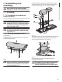
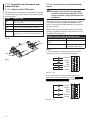


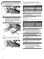


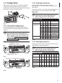


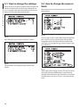

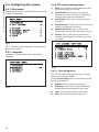
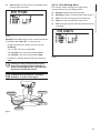
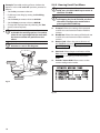


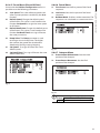

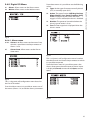

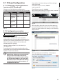
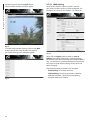
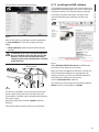

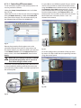
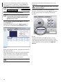
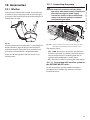

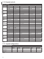
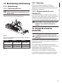
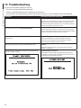


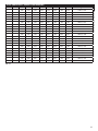

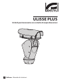


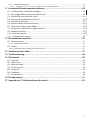


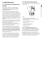


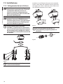
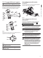

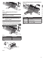
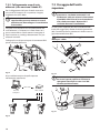
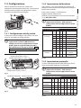
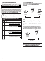
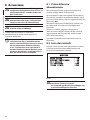
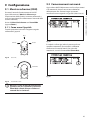

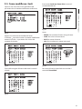
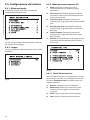

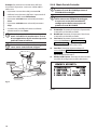

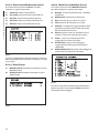

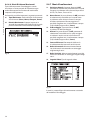
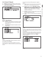
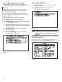

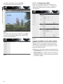
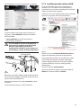
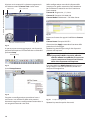


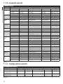
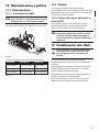


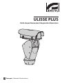


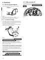

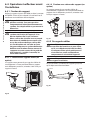


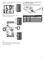
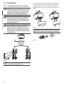
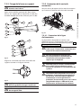
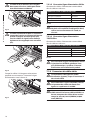
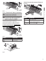

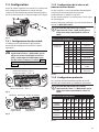

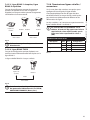


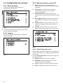


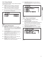
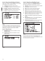
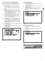
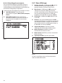
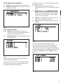

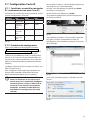

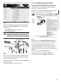


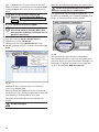


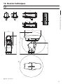


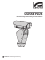


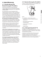


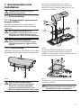

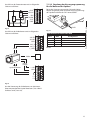
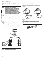
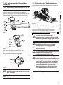
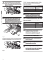

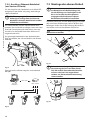

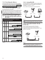
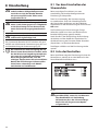

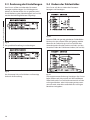
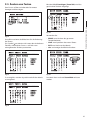

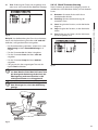
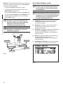
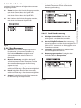

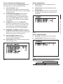
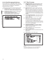
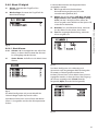
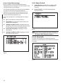
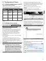


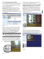
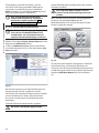
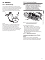

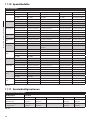
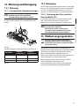
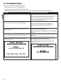


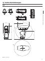
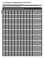


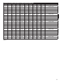


![Benutzerhandbuch - PDF-File, deutsch [Finepass FSR 5000 TDR]](http://vs1.manualzilla.com/store/data/006792778_1-53a257ab015261bce09484c018863da6-150x150.png)