1
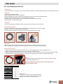
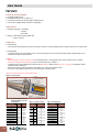
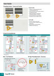
User Guide
Sealed Collet
Application
ER collets are used for applications requiring through coolant, as well as for standard cutting tools such as drills,
boring bars, end mills, reamers, taps and special tools.
They provide an effective solution for accurate controled coolant flow.
Front sealing collets are available for advanced high speed machines with through coolant spindles/turrets.
They provide maximum performance, high cutting speeds, extended tool life and high quality surface finish.
Features
•
•
•
•
•
•
A revolutionary high precision front sealing collet with 1.00mm collapsibility that has through coolant capability
Increased machining efficiency
Extended tool life
Has powerful gripping and parallel clamping
Front sealing provides protection from contamination
Fast chip removal from work piece
Advantages
• High-pressure coolant supply up to 100 bar
• Eliminates coolant flow interference
Notes
• For maximum security and clamping power, the cutting tool shank must be inserted into the collet to
a minimum depth of 2 X shank diameter
• In sealed collet JET2 the nozzle must be adjusted directly to the flute of the cutting tool
• Suitable for all shank standards
TaeguTec ER Coolit Sealed Collet
Two types:
Sealed collet jet 2
Sealed collet jet
For straight shank cutting tools
with internal coolant supply
Shank Standards
Plain Shank
WELDON/DIN 1835/B
Whistle Notch
G86
With angular double nozzle.
Coolant flow is direct to the cutting edge
- for use with standard straight shank cutting tools
(without coolant hole)
User Guide
ER - Top Clamping Nut DIN 6499
Description
The friction ER Nut has a unique two piece exclusive friction mechanism combining radial and angular self-centering movements.
Features
Unique two piece friction bearing
Radial and angular float for better concentricity.
Powerful gripping force, 50-100% higher than standard ER nut due to the friction bearing mechanism
Balanced for higher spindle speed due to unique extractor teeth design
Compact design - general dimensions and size range are the same as the standard nut
Sealed design for use with sealed collets
Operation
To insert collet: Always assemble the collet into the nut before mounting onto the collet chuck.
Inserting Procedure
Insert the collet slantwise, fitting the two protruding extractor teeth (A) into the collet groove (B).
Place the two parts onto a clean and horizontal surface.
Press down with your thumb on the back end of the collet until it clicks into place (C).
B
A
A
C
Collet Groove
Extractor Teeth
Important
Never insert the collet parallel to the extractor ring. This will chip or break the teeth of the extractor.
When unclamping the nut, the collet will self release from the chuck by means of the extractor teeth.
Extracting Procedure
1. Align the diamond-shaped engraved logo which is on the silver ring (D) to any of the key slots (E) of the nut.
2. Place the nut with the collet facing down on a clean and horizontal work surface.
3. Insert a screwdriver vertically between the nut slots and the collet – on the reverse side of the diamond shaped engraved logo (D).
4. Tilt the screwdriver outwards while helping the extraction by pushing the back of the collet in the opposite direction (F).
F
E
D
Note:
For maximum performance the clamping nut thread and collet taper must
be cleaned and oiled before use.
Recommended Clamping Torque for Standard ER &
ER-Top Clamping Nut
Nut type
ER-11
ER-11M
ER-16
ER-16M
ER-20
ER-20M
ER-25
ER-32
ER-40
ER-50
Kg × m
5
3
7
4
12
8
20
22
25
35
Important:
The torque is calculated to suit the maximum diameter
capacity of each collet. The torque should be gradually
reduced when used with a smaller shank size.
G87
User Guide
TSK Slim Collet Chuck
Features & Advantages
• Excellent accuracy & good gripping power by gentle taper angle (ER collet : 8º, TSK collet : 4º)
• Slim design for deep and cavity machining
• Suitable on high speed machining
• Variety of TSK collets (normal & coolant type)
• General machining using drill & end mill
Application
• General machining using drill & end mill
• High speed machining for Mold & Die industry
• Accurate machining using reamer & end mill
How to assemble the collet with a nut
a. Assembly Device
(provided with the set)
Insert the back end of the
collet (c) into the
assembly device (a)
b. Nut
❷ Insert the combined
part (a+c) in the nut (b)
c. Collet
❸ Pluck out the assembly device (a)
from the remaining part (b+c)
Quick-Change System
DIN 69871
HSK
BT MAS 403
Advantages
•
•
•
•
•
Taper and face contact
Ideal for High Speed Machining
High precision – low runout
Excellent rigidity
Quick and easy clamping
Quick-Change Advantages
• Quick tool change - The taper shank and the holder connect
•
•
•
•
•
•
in a quick half turn.
No thermal shock on holder taper
Flexibility in diameter and length
Eliminates the use of extension chuck
No spare parts required
T-CLICK blanks available to provide custom made tooling
Shrink clamping for solid carbide tooling
Tightening torque: 235N.m
G88
User Guide
Balanceable Collet Chuck System
• Direct reading precision rings for high grade balance
DIN 69871
HSK
BT MAS 403
• Simple procedure on all types of balancing machines
• Static and dynamic balance
Balancing Elements
Introduction
Balancing is the process of ensuring the mass distributed by a body rotates on its axis without unbalance centrifugal force.
Balancing reduces the risks of vibration, ensures lower strain on machine tool spindle, permits higher cutting data,
extends tool life and improves machining conditions.
Available measuring equipment enables unbalance to be reduced to minimal amounts. However, it would be uneconomical to
exaggerate the quality requirements. It has therefore become necessary to determine to what extent the unbalance should be reduced,
and where the optimum economic and technical compromise on balance quality requirements would be struck.
Definition
G - Balance quality (mm/s)
e - Specific unbalance (g × mm/kg)
Ω - Speed (rad/s)
N - Speed (rpm)
e= U =>U=M×e
M
M- Mass of the body (kg)
m- Mass of the unbalance (g)
r - Radius of the unbalance (mm)
U - Residual unbalance (g × mm)
Ω = 2π N = π N
30
60
Operation
Residual unbalance equals the tool’s mass (M) multiplied by its eccentricity (e).
Eccentricity measures the extent to which the tool’s weight is off-center.
It is defined as the distance from the tool’s center of the rotation to
its true center of mass.
Balancing Elements
Eccentricity is measured in microns and tool mass is measured in kilograms.
The units yield a residual unbalance in gram-millimetres.
Any two sets of mass and eccentricity that yield the same unbalance
value will have the same effect on the tool, so long as the residual
unbalance is in the same plane perpendicular to the rotation axis.
U=r×m
The residual unbalance is independent of the speed.
This value reflects the unbalance mass and its distance from
the true center of mass. The residual unbalance value is measured on
balancing machines.
G89
User Guide
Features & Advantages
• Consistent gripping force
• Excellent Accuracy (run-out : within 5㎛)
• Convenient and safe tool change using a clamping screw
• Can use THC straight collets (normal & coolant type)
Application
• Accurate machining – fine milling
– reaming
– fine boring
• Drilling – small diameter using carbide drill
– for Al or cast iron
Operation
• Tool Mounting
- Insert the tool shank between Lmax and Lmin (Fig 1) and then, turn the clamping screw clockwise until it can no longer rotate
• Tool Releasing
- To release the tool from the hydraulic chuck, turn the clamping screw in a counter clock-wise direction approximately 5 or 6
evolutions and remove the tool shank
• Notice
- Eliminate grease, coolant oil and any dirt from the internal bore of the Hydraulic chuck and tool shank prior to mounting
- Ensure the minimum chucking length (L min) is maintained (see fig 1 & table 1)
- Cylindrical tool shanks available in accordance with h6 tolerance (table 2) and Ra min =0.3㎛ (ground) and Weldon shanks
should be used in collet only
- Remove the end tool from the hydraulic chuck when not in use for long periods of time
- Do not turn the clamping screw prior to tool mounting in the hydraulic chuck
*Please refer to the backface for information tables.
Figure 1. Tool structure
Table 1. recommended minimum &
maximum depth (L) of end
tool insertion
G90
Inner bore
diameter Ø(mm)
L min
(mm)
L max
(mm)
6
27.5
37.5
8
27.5
37.5
10
32.5
42.5
12
37.5
47.5
14
37.5
47.5
16
42.5
52.5
20
42.5
52.5
25
51
61
32
55
65
Table 2. h6 tolerance range
Shank size
Ø(mm)
3
3
6
6
10
10
18
18
30
30
50
h6 tolerance
range(㎛)
0
-6
0
-8
0
-9
0
-11
0
-13
0
-16
Table 3. clamping torque
Inner bore
diameter Ø(mm)
Calmping
torque(N*m)
6
10
8
25
10
40
12
65
14
90
16
120
20
240
25
260
32
450
User Guide
Thermal
Chucking System
Chucking System
The thermal T-Shrink ER Collet Chucking System is an enhancement to the existing popular ER system.
The T-Shrink collets utilize the thermal shrink phenomena for rigid clamping of solid carbide cutters.
This new system provides higher torque, precision runout and better repeatability.
The T-Shrink Collets with their slim design and different projection length
allows the user to reach into deeper cavities and perform narrow milling applications.
TaeguTec offers a complete system for T-Shrink ER Collets,
including a uniquely designed heating unit with a portable heating handle.
The unit is equipped with a high-tech temperature control for easy and
practical use at the machining center or in the tool room.
For carbide tools only
L(mm)
•
•
•
•
•
•
•
•
•
•
•
357µm
609µm
85
Features
Max T.I.R
10µm
Slim design to maximise effectiveness and application access
Flexible - fits into standard ER chucks
High torque transfer
Rigid clamping of carbide tools
High precision – low runout
Perfect repeatability
Vibration damping
Coolant JET2 available
Symmetrical design for High Speed Machining
Quick and easy tool changing
Unique T-Shrink heating unit with portable handle
0.003mm
Clamping time
15~45 sec
G91
User Guide
DIN 69871
T-Short ER32
New short holder for ER32 spring
and shrink collets for maximun
rigidity and improved cutting conditions
HSK DIN 69893
BT MAS-403
Advantages
Short overhang
Suitable for T-short and T-shrink collets
• High gripping force
• Reduces vibration
• Improved runout and repeatability
• Balanced to G2.5, 20,000 rpm
• Symmetrical design for High Speed Machining
• Cost effective
•
•
G92
User Guide
GTI-Tap Attachment
Description
Short tap chucks for ER collets
Application
Axial-float/tension/compression type for CNC milling machines and lathes with
reversing motors and rigid tap ping
Features
• Compensates for machine feed and tap pitch variance
• Floating mechanism compensates for misalignment between tap and workpiece
• Right and left-hand tapping
Advantages
• Practical and efficient tap holding by the ER spring collet without using drive jaw
• Compact design for minimal clearance applications
• Heavy-duty design for high torque drive ensures the same accuracy as the tap itself
DIN 69871
BT MAS-403
Straight Shank
Operation
For through and blind hole tapping:
1 Enter feed rate according to thread pitch (or 1-2% lower), and set spindle to starting point with 0.08mm clearance.
2 Start spindle forward
3 Stop feed and rotation with right hand rotation
until reaching desired
depth.
and reverse to starting
point.
/ Holder for Adjustable Drilling Diameter
Adjustable Rotary Tool Holder Indexable Insert Drills
Application
• For use on machining centres and drilling machines
Features
•
•
•
•
Diameter adjustment range – 0.30mm to +1.30mm
Guaranteed bore tolerance of ±0.02mm
Through the shank coolant design or “Type B” coolant through the flange
Coolant pressure up to 70 bar
Min:
D-0.3
Max:
D+1.3
Operation
Best results are achieved on a preset machine or similar device.
A
B
1. To adjust the offset - slacken clamp screw A
2. Adjust with screw B and set to minus 0.20mm below required diameter
3. Tighten clamp screw A
4. Take a trial cut and measure the bore diameter
5. Adjust to suit requirements
6. Final adjustment can be made on the machine using a dial indicator or on a presentable
G93
User Guide
GYRO - Radial and Angular Alignment of Tool Holder
Advantages
• Easy adjustment for correcting misalignment between chuck and turret axis (drill and workpiece)
• Precise and efficient tool clamping with ER collets and ER sealed Coolit Jet collets
• Quick functional adjustment is made on machine by using plug and ring gauge kit
Operation
Operating instructions are provide with each tool supplied.
Notes
• Coolant supply should be minimum 10 bar and maximum 80 bar for small diameter oil hole drills
- ranging from 3~20mm. (the normal machine pressure of 4 bar is insufficient)
• Coolant filtration is important to eliminate chips from blocking the drill oil hole
• To ensure maximum performance of the GYRO, the backlash of the turret indexing
and support axis mechanism should be checked and re-adjusted according to
the machine standard
GYRO - Radial and Angular Alignment of Tool Holder
Adjustable Tool Holder for Easy Adjustment of Radial and Angular Misalignment
Application
Gyro is a rugged and adjustable toolholder to solve drilling, tapping and reaming problems encountered on CNC
and turret lathes. Its unique design allows smooth and easy adjustment of radial and angular misalignment
between chuck and turret.
yro reduces total machining time by making it possible to complete machining of holes in one drilling step
G
and achieve tolerances as close as 0.01mm, thereby eliminating subsequent boring or reaming operations.
• A breakthrough in drilling technology for CNC lathes
• Dramatic increase in tool performance at reduced cost
T.I.R. max 0.02mm
Features
• Enables high precision drilling to a close tolerance of 0.01mm, to be performed
as a final boring operation on CNC lathes
• Reduces machining cycle time by completing the bore in one drilling step, eliminating
secondary turning and boring operations
• Prolongs tool life tenfold, especially when using HSS, solid and
brazed carbide drills, taps and reamers
• Permits increase in speeds and feeds by up to 300%
• Coolant supply through the centre of the unit via the tool shoulder for oil fed drilling
Angular Adj. 1˚
TaeguTec GFI ER - Floating Reamer Collet Chuck
Floating
chuck adjusts the misalignment between reamer and workpiece hole to
ensure the same accuracy as the reamer itself.
Application
The GFI floating chuck is a unique holder to compensate for the radial misalignment existing
in the reaming operations carried out on vertical and horizontal machine tools.
Features
• Radial self floating mechanism compensates misalignment between reamer and workpiece to
ensure the same tolerance as the reamer itself
• The special self centering mechanism eliminates tapered and oversized bores
Advantages
• Unique ball bearing and axle drive shaft structure enables vertical and horizontal machining
• Precise and efficient clamping with ER spring collets of ER Coolit collets
G94
Radial Adj. 2.0mm
User Guide
Machining Center Shank Details
0
30° -15°
0
30° -15°
7/24 Taper
L5
d
g
D1
d1 d2
b
t
t
L4
7/24 Taper
D4 D5 D6
d1 d2
b
j
D
L2
V
L3
y
L1
X
j
X1
t1
30
40
45
50
Taper
No
30
40
45
50
TaeguTec No
MAS
ISO
ANSI
DIN
MAS
ISO
ANSI
DIN
MAS
ISO
ANSI
DIN
MAS
ISO
ANSI
DIN
TaeguTec No
MAS
ISO
ANSI
DIN
MAS
ISO
ANSI
DIN
MAS
ISO
ANSI
DIN
MAS
ISO
ANSI
DIN
D1
31.75
Shank
L4
31.75
44.45
44.45
44.45
44.45
57.15
57.15
57.15
57.15
69.85
69.85
69.85
69.85
48.4 ±0.2
t
e

D4
0
44.7 -0.5
0
44.7 -0.5
50 max
0
-0.5
0
-0.5
57.4
57.4
63 max
0
-0.5
0
-0.5
70.1
70.1
80max
d1
14
19
19.0max
18.5
19.0max
23
23.4max
22.5
23.4max
27
28.4max
26.5
28.0max
d2
12.5
H8
44.3 -0.5
53
0
56.25-0.5
0
56.25-0.5
0
56.25-0.5
73
0
75.25-0.5
0
75.25-0.5
0
75.25-0.5
85
0
91.25-0.5
0
91.25-0.5
0
91.25-0.5
13
17 H8
17 H8
16.4 +0.4
0
17 H7
21 H8
21 H7
20.4 +0.4
0
21 H7
25 H8
25 H7
24.8 +0.4
0
25 H7
D5
46 H8
0
V
y
L1
X
f
Thread
g
L2
L3
M12
24min 34min
M12×1.75
M16×2
M16×2
M16×2
M16×2
M20×2.5
M20×2.5
M20×2.5
M20×2.5
M24×3
M24×3
M24×3
M24×3
24min
30min
32min
30min
32min
38min
40min
38min
40min
45min
47min
45min
47min
L4
7.0 +0.5
0
b
16.1
Taper
L5
H12
t
t1
0
17min 16.3 -0.2
j

38
45max
14
0
47.8 -0.3
65.4 ±0.2
0
68.4 -0.3
0
68.4 -0.3
0
68.4 -0.3
82.8 ±0.2
0
82.70 -0.3
0
82.7 -0.3
0
82.70 -0.3
101.8 ±0.2
0
101.75 -0.3
0
101.75 -0.3
0
101.75 -0.3
D3
L2
L3
• DIN 69871•
• ISO, ANSI •
L1

D3 D4 D5 D6
D1
• MAS BT-403 •
Taper
No
d
g
e
f
20
0
50 -0.1
63 H8
0
63.55 -0.1
0
63.55 -0.1
0
63.55 -0.1
H8
85
0
82.55 -0.1
0
82.55 -0.1
0
82.55 -0.1
100 H8
0
97.50 -0.1
0
98.45 -0.1
0
97.50 -0.1
Flange
25
30
35
15.90
15.90
+0.1
15.90 0
15.90
15.90
+0.1
15.82 0
15.90
15.90
0
15.82 -0.1
15.90
33.5min 5.5 +0.5
0
43min 9.0 +0.5
0
42.5min 8.2 +0.5
0
4.75 +0.5
00
42.5min 8.2 +0.5
0
53min 11.0 +0.5
0
52.5min 10.0 +0.5
0
5.25 +0.5
0
52.5min 10.0 +0.5
0
62min 13.0 +0.5
0
61.5min 11.5 +0.5
0
5.75 +0.5
0
61.5min 11.5 +0.5
0
V
X
13.6 ±.0.1
4
11.1 ±.0.1
16.6 ±.0.1
11.1 ±.0.1
11.1 ±.0.1
11.1 ±.0.1
21.2 ±.0.1
11.1 ±.0.1
11.1 ±.0.1
11.1 ±.0.1
23.2 ±.0.1
11.1 ±.0.1
11.1 ±.0.1
11.1 ±.0.1
3.75 0
5
+0.15
3.75 0
+0.15
3.75 0
+0.15
3.75 0
+0.15
6 0
+0.15
3.75 0
+0.15
3.75 0
+0.15
3.75 0
7
+0.15
3.75 0
+0.15
3.75 0
+0.15
3.75 0
16.1 H12
16.1 H12
16.1 H12
+0.2
16.1
16.1 H12
19.3 H12
19.3 H12
19.3 H12
+0.2
19.3 0
19.3 H12
25.7 H12
+0.2
25.7 0
25.7 H12
0
16.4 -0.4
0
21min 22.6 -0.2
0
22.8 -0.4
0
22.8 -0.4
0
16.4 -0.4
0
26min 29.1 -0.2
0
29.1 -0.4
0
29.1 -0.4
29 max
0
31min 35.5 -0.4
0
35.5 -0.4
0
35.5 -0.4
0
35.5 -0.4
y
8 +0.1
2 ±.0.4
17.633
8
3.2 ±.0.1
2 ±.0.4
3.2 ±.0.1
3.18
3.2 ±.0.1
3 ±.0.4
3.2 ±.0.1
3.18
3.2 ±.0.1
3 ±.0.4
3.2 ±.0.1
3.18
3.2 ±.0.1
17.808
25.375
24.500
24.500
24.500
33.000
33.029
33.029
33.029
40.158
40.173
40.173
40.173
7
10
7
7
7
12
7
7
7
15
7
7
7
10
+0.1
0
12
+0.1
0
15
+0.1
0
0
25.0 -0.4
0
26.0 -0.4
0
25.0 -0.4
0
31.3 -0.4
0
32.5 -0.4
0
31.3 -0.4
0
37.7 -0.4
0
40.4 -0.4
0
37.7 -0.4
d
0
-0.3
15
Reference
X1
+0.15
d3
19 0
0
18.50 -0.3
0
18.5-0.3
0
24.00 -0.3
0
24 -0.3
0
30.00 -0.3
30
0
-0.3
D6
56.144
59.3
75.679
72.30 ±.0.05
72.30 ±.0.05
72.30 ±.0.05
100.216
91.35 ±.0.05
91.35 ±.0.05
91.35 ±.0.05
107.25 ±.0.05
107.25 ±.0.05
107.25 ±.0.05
107.25 ±.0.05
G95
User Guide
MT Socket Details
Taper
No
α°
d
g
D
h
G96
L1
L2
z
Taper
Taper Angle
(α˚)
D
d
L1
L2
(Max) (Max)
g
h
z
MT0
1/19.212
0.05205
1˚ 29′ 27″
9.045
6.7
52
49
4.1
15
1
MT1
1/20.047
0.04988
1˚ 25′ 43″
12.065
9.7
56
52
5.4
19
1
MT2
1/20.020
0.04995
1˚ 25′ 50″
17.780
14.9
67
62
6.6
22
1
MT3
1/19.922
0.05020
1˚ 26′ 16″
23.825
20.2
84
78
8.2
27
1
MT4
1/19.254
0.05194
1˚ 29′ 15″
31.267
26.5
107
98
12.2
32
1.5
MT5
1/19.002
0.05263
1˚ 30′ 26″
44.399
38.2
135
125
16.2
38
1.5
MT6
1/19.180
0.05214
1˚ 29′ 36″
63.348
54.6
188
177
19.3
47
2
MT7
1/19.231
0.05200
1˚ 29′ 22″
83.058
71.1
258
241
28.8
69
2