1
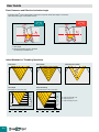
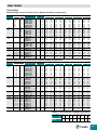
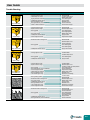
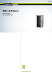
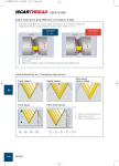
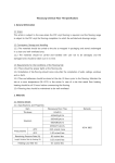
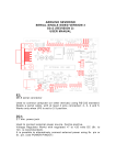
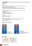
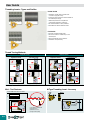
User Guide Threading Inserts - Types and Profiles Partial Profile •Suitable for a wide range of pitches with a common angle (60°or 55°) •Inserts with small root-corner radius suitable for the smallest pitch range. •Additional operations to complete the outer/internal diameter is necessary. •Not recommended for mass production. •Eliminates the need for different inserts. Full Profile •Performs complete thread profile. •Root corner radius is suitable only for the relevant pitch. •Recommended for mass production. •Suitable for one profile only. Thread Turning Methods External Thread Internal Thread Right-Hand Thread Left-Hand Thread Right-Hand Thread Left-Hand Thread Change anvil to negative(1) Change anvil to negative(1) Change anvil to negative(1) Change anvil to negative(1) • (1)See page B24 Mini - Tool Features (1) (2) (3) M-Type Threading Insert - Accuracy øD ≥ M8; 5/16˝- UN; 1/16˝- NPT 4H-8H / 1B-3B ➞ A 0.00 Indexability: ±0.025mm (1) Smallest possible thread (2) All tolerances (3) Minimum run-out (4) High surface quality B 22 (1) (1) Insert indexability accuracy: ±0.015mm User Guide Thread Helix Angle and Anvil Selection Helix Angle λ Evaluation 10 4 5 6 8 12 6 4 2 Pitch-TPI Pitch (mm) 8 24 0 50 (1) 100 150 직경-D (mm) 200 20×P  D λ°= β -Effective inclination angle. P - Pitch (mm) D - Effective diameter of thread (mm) λ - Angle of inclination 1×P 3.14 · D tg λ = Anvil Selection According to Thread Helix Angle λ Standard Thread Helix Angle λ > 4° Inclination Angle β 4.5° 3°- 4° 2°- 3° 1°- 2° 3.5° 2.5。 1.5° Negative Anvils 0°- 1° 0.5° -0.5° -1.5° Anvil Designation I(IC) Toolholder 16 EX RH OR IN LH AE 16 +4.5 AE 16 +3.5 AE 16 +2.5 AE 16 AE 16 +0.5 AE 16 -0.5 AE 16 -1.5 (3/8) EX LH OR IN RH Al 16 +4.5 Al 16 +3.5 Al 16 +2.5 AI 16 Al 16 +0.5 Al 16 -0.5 Al 16 -1.5 22 EX RH OR IN LH AE 22 +4.5 AE 22 +3.5 AE 22 +2.5 AE 22 AE 22 +0.5 AE 22 -0.5 AE 22 -1.5 (1/2) EX LH OR IN RH Al 22 +4.5 Al 22 +3.5 Al 22 +2.5 AI 22 Al 22 +0.5 Al 22 -0.5 Al 22 -1.5 27 EX RH OR IN LH AE 27 +4.5 AE 27 +3.5 AE 27 +2.5 AE 27 AE 27 +0.5 AE 27 -0.5 AE 27 -1.5 (5/8) EX LH OR IN RH Al 27 +4.5 Al 27 +3.5 Al 27 +2.5 Al 27 Al 27 +0.5 Al 27 -0.5 Al 27 -1.5 22U EX RH OR IN LH AE 22U+4.5 AE 22U+3.5 AE 22U+2.5 AE 22U AE 22U+0.5 AE 22U-0.5 AE 22U-1.5 (1/2U) EX LH OR IN RH Al 22U +4.5 Al 22U+3.5 Al 22U+2.5 Al 22U Al 22U+0.5 Al 22U-0.5 Al 22U-1.5 27U EX RH OR IN LH AE 27U+4.5 AE 27U+3.5 AE 27U+2.5 AE 27U AE 27U+0.5 AE 27U-0.5 AE 27U-1.5 (5/8U) EX LH OR IN RH Al 27U +4.5 Al 27U+3.5 Al 27U+2.5 Al 27U Al 27U+0.5 Al 27U-0.5 Al 27U-1.5 ACME STUB ACME TRAPEZE (DIN 103) ROUND (DIN 405) Pitch TPI MM 2.5 10 8 3.5 7 5.5 6 5 5 6 4 3.5 3 2.5 2 1.5 8 10 12 16 Pitch TPI MM 2.5 10 Special Holder Required 9 3 9 AE or Al+4.5° AE or Al+3.5° AE or Al+2.5° Standard Anvil (Supplied with toolholder) AE or Al+0.5° 5 10 20 30 40 50 60 AE Anvils:EX-RH and IN-LH Toolholders Al Anvils: IN-RH and EX-LH Toolholders. Tool Holder PARTIAL PROFILES 60° PARTIAL PROFILES 55° ISO, UN,WHITworth, NPT, BSPT 70 80 mm Diameter 3 8 3.5 7 5.5 6 5 5 6 4 3.5 3 2.5 2 1.5 8 10 12 16 AE or Al+2.5° Standard Anvil (Supplied with toolholder) 30 Special Holder Required 9 AE or Al+3.5° 20 H1 remains constant for every anvil combination. Anvils for positive inclination angle β applicable when turning RH thread with RH holder or LH thread with LH holders. Pitch TPI MM 2.5 10 AE or Al+4.5° 10 (1) AMERICAN BUTTRESS SAGENGEWINDE (DIN-513) Special Holder Required 5 Anvils for negative inclination β used when turning RH thread with LH holder or LH thread with RH holder. 40 50 60 AE Anvils:EX-RH and IN-LH Toolholders Al Anvils: IN-RH and EX-LH Toolholders. 70 3 8 3.5 7 5.5 6 5 5 6 4 3.5 3 2.5 2 1.5 8 10 12 16 80 mm Diameter AE or Al+2.5° Standard Anvil (Supplied with toolholder) Change to Negative Anvil AE or Al-1.5° 5 10 20 30 40 50 60 AE Anvils:EX-RH and IN-LH Toolholders 70 80 mm Diameter Al Anvils: IN-RH and EX-LH Toolholders. Tool Holder Replacing the standard anvil with a negative angle anvil will eliminate side rubbing B 23 User Guide Flank Clearance and Effective Inclination Angle Inclination angle β of the cutting edges correspond to a specific thread helix angle λ and insures equal clearance angle on both sides of insert. Correct Correct αL = αR αL = αR α - Flank clearance angle λ - Helix angle β -Effective inclination angle is achieved by selecting the suitable anvil Infeed Methods for Threading Operations Flank Infeed Radial Infeed Alternating Flank Infeed Flank Equal Equal depth of cut for each pass Flank Diminishing Diminished depth of cut for each pass D1/2 D2/2 H/2 D3/2 Dn/2 △D/2 U/2 D2 D3 Dn D1 = = = 2 2 2 2 B 24 D1/2 D2/2 D3/2 Dn/2 Dn+1/2 △D/2 U/2 Dn Dn+1 D1 D 2 D 3 > > > 2 2 2 2 > 2 H - Depth of thread profile (on Ø) D - Depth of pass (on Ø) U - Depth of finishing pass (on Ø) User Guide Cutting Data Maximum depth of first cut for CNC control / External Threading - M-Type Inserts Full Profile mm Pitch Insert Designation No. of passes Min. Max. TPI 16 ERM 1.00 ISO ISO 1.00 5 9 16 ERM 1.25 ISO Metric 1.25 6 11 16 ERM 1.50 ISO 1.50 6 12 16 ERM 1.75 ISO 1.75 8 13 16 ERM 2.00 ISO 2.00 8 14 16 ERM 2.50 ISO 2.50 10 15 16 ERM 3.00 ISO 3.00 12 17 16 ERM 24 UN American 24 5 9 16 ERM 20 UN UN 20 6 10 16 ERM 18 UN 18 6 11 16 ERM 16 UN 16 7 12 16 ERM 16 UN 6 13 16 ERM 12 UN 12 8 14 16 ERM 8 UN 8 12 17 16 ERM 19 W British 19 6 11 16 ERM 16 W BSW 16 7 12 16 ERM 14 W 14 8 13 16 ERM 11 W 11 9 14 16 ERM 18 NPT NPT 18 10 20 16 ERM 14 NPT 14 13 26 16 ERM 11.5 NPT 11.5 15 24 16 ERM 8 NPT 8 17 30 16 ERM 6 RND Round 6 9 20 Partial 0.50-1.50 (1) 0.22 48-16 16 ERM A 60 Profile 60° 1.75-3.00 14-8 16 ERM G 60 0.50-3.00 48-8 16 ERM AG 60 3.50-5.00 7-5 22 ERM N 60 Partial 1.75-3.00 14-8 16 ERM G 55 Profile 55° 0.50-3.00 48-8 16 ERM AG 55 Max. Depth for First Pass (D1) mm Low Carbon Steel Eq. Dim. 0.34 0.51 0.42 0.63 0.46 0.69 0.48 0.72 0.50 0.75 0.53 0.80 0.56 0.84 0.34 0.51 0.42 0.63 0.46 0.69 0.47 0.71 0.46 0.69 0.50 0.75 0.56 0.84 0.35 0.52 0.47 0.71 0.50 0.75 0.44 0.66 0.24 0.36 0.24 0.36 0.27 0.40 0.31 0.46 0.42 0.63 0.33 0.20 0.50 0.75 0.24 0.36 0.41 0.62 High Carbon Steel Eq. Dim. 0.31 0.46 0.38 0.57 0.41 0.62 0.43 0.65 0.45 0.68 0.48 0.72 0.50 0.76 0.31 0.46 0.38 0.57 0.41 0.62 0.42 0.64 0.41 0.62 0.45 0.68 0.50 0.76 0.32 0.47 0.42 0.64 0.45 0.68 0.40 0.59 0.22 0.32 0.22 0.32 0.24 0.36 0.28 0.41 0.38 0.57 0.30 0.18 0.45 0.68 0.22 0.32 0.37 0.56 Alloy Steel Eq. Dim. 0.27 0.41 0.34 0.50 0.37 0.55 0.38 0.58 0.40 0.60 0.42 0.64 0.45 0.67 0.27 0.41 0.34 0.50 0.37 0.55 0.38 0.57 0.37 0.55 0.40 0.60 0.45 0.67 0.28 0.42 0.38 0.57 0.40 0.60 0.35 0.53 0.19 0.29 0.19 0.29 0.22 0.32 0.25 0.37 0.34 0.50 0.26 0.14 0.40 0.60 0.19 0.29 0.33 0.50 Stainless Steel Eq. Dim. 0.22 0.33 0.27 0.41 0.30 0.45 0.31 0.47 0.33 0.49 0.34 0.52 0.36 0.55 0.22 0.33 0.27 0.41 0.30 0.45 0.31 0.46 0.28 0.41 0.33 0.49 0.36 0.55 0.21 0.31 0.31 0.46 0.33 0.49 0.29 0.43 0.16 0.23 0.14 0.22 0.18 0.26 0.20 0.30 0.27 0.41 0.21 0.31 0.33 0.49 0.16 0.23 0.27 0.40 0.50 0.22 0.45 0.20 0.40 0.18 0.33 0.14 0.75 0.33 0.68 0.30 0.60 0.26 Nonferrous Aluminum Eq. Dim. 0.48 0.71 0.59 0.88 0.64 0.97 0.67 1.01 0.70 1.05 0.74 1.12 0.78 1.18 0.48 0.71 0.59 0.88 0.64 0.97 0.66 0.99 0.64 0.97 0.70 1.05 0.78 1.18 0.49 0.73 0.66 0.99 0.70 1.05 0.62 0.92 0.34 0.50 0.34 0.50 0.38 0.56 0.43 0.64 0.59 0.88 0.46 0.70 1.05 0.34 0.50 0.57 0.87 0.49 0.21 0.70 0.31 1.05 0.46 Maximum depth of first cut for CNC control / Internal Threading - M-Type Inserts Full Profile Pitch mm Insert Designation No. of passes Min. Max. TPI ISO 1.5011 IRM 1.50 ISO 10 20 Metric 1.0016 IRM 1.00 ISO 9 16 1.2516 IRM 1.25 ISO 9 16 1.5016 IRM 1.50 ISO 10 20 1.7516 IRM 1.75 ISO 11 18 2.0016 IRM 2.00 ISO 12 21 2.5016 IRM 2.50 ISO 14 21 3.0016 IRM 3.00 ISO 16 22 American 2016 IRM 20 UN 7 13 UN 1816 IRM 18 UN 8 15 1616 IRM 16 UN 11 19 1416 IRM 14 UN 11 20 1216 IRM 12 UN 12 21 816 IRM 8 UN 14 20 British 1916 IRM 19 W 7 12 BSW 1616 IRM 16 W 9 14 1416 IRM 14 W 10 16 1116 IRM 11 W 12 19 NPT 14 16 IRM 14 NPT 21 35 11.516 IRM 11.5 NPT 21 33 816 IRM 8 NPT 20 34 Round 616 IRM 6 RND 12 24 48-16 06 IRM A 60 0.50-1.25 Partial 48-16 08 IRM A 60 0.50-1.50 Profile 60° (1) 48-16 11 IRM A 60 0.50-1.50 48-16 16 IRM A 60 0.50-1.50 14-8 16 IRM G 60 1.75-3.00 48-8 16 IRM AG 60 0.50-3.00 7-5 22 IRM N 60 3.50-5.00 14-8 16 IRM G 55 1.75-3.00 Partial 48-8 16 IRM AG 55 0.50-3.00 Profile 55° • (1)A s per the number of passes for the relevant pitch Low Carbon Steel Eq. Dim. 0.20 0.30 0.14 0.20 0.19 0.28 0.20 0.30 0.21 0.32 0.22 0.33 0.23 0.34 0.24 0.35 0.20 0.30 0.20 0.30 0.20 0.30 0.21 0.31 0.23 0.34 0.24 0.36 0.28 0.42 0.26 0.39 0.27 0.41 0.31 0.46 0.13 0.20 0.17 0.25 0.23 0.34 0.30 0.46 0.22 0.33 0.13 0.20 0.13 0.20 0.13 0.20 0.22 0.33 0.14 0.21 0.23 0.34 0.34 0.50 0.14 0.20 Max. Depth for First Pass (D1) mm High Carbon Steel Eq. Dim. 0.18 0.27 0.13 0.18 0.17 0.25 0.18 0.27 0.19 0.29 0.20 0.30 0.21 0.31 0.22 0.32 0.18 0.27 0.18 0.27 0.18 0.27 0.19 0.28 0.21 0.31 0.22 0.32 0.25 0.38 0.23 0.35 0.24 0.37 0.28 0.41 0.12 0.18 0.15 0.23 0.21 0.31 0.27 0.41 0.20 0.30 0.12 0.18 0.12 0.18 0.12 0.18 0.20 0.30 0.13 0.19 0.21 0.31 0.31 0.45 0.13 0.18 Alloy Steel Eq. Dim. 0.16 0.24 0.11 0.16 0.15 0.22 0.16 0.24 0.17 0.26 0.18 0.26 0.18 0.27 0.19 0.29 0.16 0.24 0.16 0.24 0.16 0.24 0.17 0.25 0.18 0.27 0.19 0.29 0.22 0.34 0.21 0.31 0.22 0.33 0.25 0.37 0.10 0.16 0.14 0.20 0.18 0.27 0.24 0.37 0.18 0.26 0.10 0.16 0.10 0.16 0.10 0.16 0.18 0.26 0.11 0.17 0.18 0.27 0.27 0.40 0.11 0.16 Stainless Steel Eq. Dim. 0.12 0.18 0.09 0.13 0.12 0.18 0.12 0.18 0.14 0.21 0.14 0.21 0.15 0.22 0.16 0.23 0.12 0.18 0.12 0.18 0.13 0.20 0.13 0.19 0.15 0.22 0.16 0.23 0.17 0.25 0.17 0.25 0.18 0.27 0.20 0.30 0.08 0.12 0.11 0.16 0.14 0.20 0.20 0.30 0.14 0.21 0.08 0.13 0.08 0.13 0.08 0.13 0.14 0.21 0.09 0.14 0.15 0.22 0.22 0.33 0.09 0.13 Nonferrous Aluminum Eq. Dim. 0.28 0.42 0.20 0.28 0.27 0.39 0.28 0.42 0.29 0.45 0.31 0.46 0.32 0.48 0.34 0.50 0.28 0.42 0.28 0.42 0.28 0.42 0.29 0.43 0.32 0.48 0.34 0.50 0.39 0.59 0.36 0.55 0.38 0.57 0.43 0.64 0.18 0.28 0.24 0.35 0.32 0.48 0.42 0.64 0.31 0.46 0.18 0.28 0.18 0.28 0.18 0.28 0.31 0.46 0.20 0.29 0.32 0.48 0.48 0.70 0.20 0.28 Number of Cutting Passes for Regular Type Inserts Pitch Number of Passes mm TPI 0.5 48 1.0 24 4-6 5-9 1.5 16 2.0 12 2.5 10 3.0 8 4.0 6 6.0 4 5-12 6-14 7-15 8-17 10-20 11-22 • For mini-tools (06IR or 08IR) add 1÷3 passes. Increase for hard materials B 25 User Guide Recommended Cutting Conditions According to DIN/ISO513 and VDI 3323 Tensile Material ISO < 0.25 %C Annealed Non-alloy steel, >= 0.25 %C Annealed P K 420 125 1 160 180 105 100 P30 Cutting Speed (m/min) 2 160 180 105 100 250 3 150 160 100 90 cutting steel 750 220 4 150 160 100 90 >= 0.55 %C Annealed Quenched and tempered Low alloy steel and cast steel (less than 5% alloying elements) 1000 300 5 130 140 85 85 Annealed 600 200 6 80 80 60 60 930 275 7 130 130 85 85 Quenched and tempered 1000 300 8 120 120 80 80 1200 350 9 95 100 60 60 Ferritic/martensitic Stainless steel and cast steel Martensitic Austenitic Gray cast iron (GG) Ferritic Cast iron nodular (GGG) Ferritic Aluminumcast, alloyed 200 10 80 80 50 5 325 11 60 60 40 40 680 200 12 105 110 50 50 820 240 13 150 160 100 100 600 180 14 70 80 45 45 160 15 120 100 250 16 130 100 180 17 130 100 260 18 100 80 130 19 130 70 230 20 100 50 60 21 1400 800 100 22 500 380 75 23 700 400 90 24 420 330 Pearlitic Ferritic Pearlitic Not cureable Cured <=12% Si Not cureable Cured >12% Si >1% Pb High temp. 130 25 240 180 Free cutting 110 26 300 200 90 27 400 280 Electrolitic copper 100 28 120 100 29 300 180 Brass Duroplastics, fiber plastics Hard rubber Fe based High temp. alloys 680 1100 Pearlitic Non metallic Ni or Co based Annealed Cured Annealed Cured Cast 30 300 180 200 31 60 30 280 32 50 30 250 33 30 20 350 34 20 10 320 Rm 400 Titanium, Ti alloys Alpha+beta alloys cured Hardened steel Chilled cast iron Cast iron nodular Rm 1050 Hardened Hardened Cast Hardened 35 20 10 36 140 100 37 50 30 55 HRc 38 40 25 60 HRc 39 30 20 400 40 30 20 55 HRc 41 20 15 * For more information of material groups, see the TaeguTec concise catalogue "Material conversion Table" section. Steel B 26 TT8010 190 Copper alloys H Group No. TT9030 850 Aluminumwrought alloy S HB TT7010 650 Malleable cast iron N Uncoated Material cast steel, free < 0.55 %C Quenched and tempered High alloy steel, cast steel Annealed and tool steel. Quenched and tempered M Coated Brinell Strength (N/mm2) Stainless Steel Cast Iron Nonferrous High Temp. Alloys Hardened Steel User Guide Trouble Shooting Problem Premature Wear Caused by Solution Cutting speed too high Infeed depth too small Reduce RPM Increase depth of cut Modify flank infeed Use coated grade Apply coolant Reselect anvil Check turned dia. Check center height Highly abrasive material Inadequate coolant supply Wrong inclination anvil Wrong turned dia. prior to threading Insert is above center line Poor chip control Inadequate coolant supply Center height incorrect Reduce RPM Reduce depth of cut Use coated grade Use tougher grade Modify flank infeed Apply coolant Adjust center height Excessive heat in cutting zone Reduce RPM Cutting speed too high Depth of cut too large Wrong grade Chipped Edge Reduce depth of cut Check turned dia. Plastic Deformation Wrong grade Use coated grade Inadequate coolant supply Apply more coolant Cutting edge too cold Increase RPM Use harder grade Increase depth of cut Wrong grade Use coated grade Inadequate coolant supply Apply coolant Cutting edge too cold Depth of cut too large Increase RPM Reduce depth of cut Increase number of infeed passes Use tougher grade Check turned dia. Adjust center height Modify flank infeed Reselect anvil Reduce tool overhang Built-Up Edge Broken Nose during 1st Pass Poor Surface Finish Wrong grade Wrong turned dia. prior to threading Corner height incorrect Infeed depth too shallow Wrong inclination anvil Tool overhang too long Wrong cutting speed Excessive heat in cutting zone Poor chip control Inadequate coolant supply Wrong inclination anvil Tool overhang too long Center height incorrect Poor Chip Control Excessive heat in cutting zone Wrong grade Inadequate coolant supply Wrong turned dia. prior to threading Increase RPM Reduce RPM Reduce depth of cut Modify flank infeed Apply coolant Reselect anvil Reduce tool overhang Check center height Reduce RPM Change depth of cut Check turned dia. Use coated grade Check turned dia. Use M-type insert Apply coolant Check turned dia. B 27