1
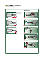
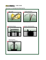
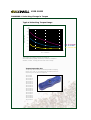
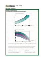
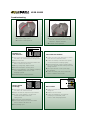
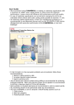
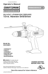
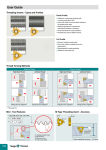
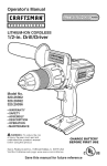
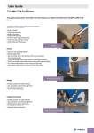
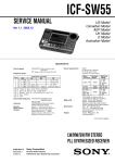
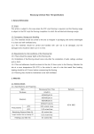
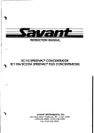
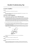
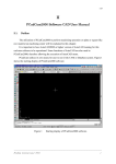
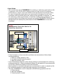
User Guide
• We recommend using CHAMDRILL in rotating or stationary applications with
a maximum of 0.02 mm outer cutting points or chisel runout for optimum
performance. Larger runout will influence drill performance and hole quality.
• In case of stationary applications we recommend clamping the drill in an
orientation which directs both outer cutting points parallel to machine “X” axis.
• On stationary (lathe) applications, if there are misalignment problems it is
recommended to use alignment devices such as the ISCAR/ETM GYRO device.
Misalignment will cause poor performance of the CHAMDRILL or even tool
breakage!
GYRO
Misalignment Correction Device for
Stationary Operation
T.I.R. max. 0.02
Angular Adj. 1°
Radial Adj. D2.0
• If chip formation or chip evacuation problems are encountered, follow these
recommendations:
1. Reduce cutting speed by 10%
2. Increase internal coolant pressure
3. Apply a pecking cycle
• Use of internal and external coolant during drilling is recommended for achieving
prolonged edge life. When only external coolant can be applied it is recommended
to drill into a maximum depth of 2X the drill diameter.
• Semi-synthetic or emulsion lubricants are recommended in order to extend tool life.
• Dry machining should not be performed under any circumstances.
• The new CHAMDRILLs can be clamped in ISCAR tooling systems such as:
1. Collet chucks
2. Side lock adapters
3. Power/hydraulic chucks
• We recommend:
- JET 2 collet chucks for internal and external coolant jets.
- Using CHAMDRILL in SHORTIN adaptation with collets, for achieving higher
tool life and improved performance.
- Drilling sloped surfaces of a maximum 6°. Reduce feed by 30-50% when
penetrating a sloped surface. Recommended exit surface angle is a maximum
of 30°. In that case feed should be reduced by 30-50%. Sloped surfaces of
more than 6° require spot or pre-hole centering to avoid drill deviation or poor
drill performance.
• Both options of stacked plate drilling are possible – with and without gap. (A minimum
gap of 2 mm between plates is recommended)
• Interrupted cut has direct influence on hole accuracy, quality and drill tool life.
• CHAMDRILL can not be used on FITBORE or any other radial adjustment
adaptation device.
• Before clamping a new drilling head, apply some oil in the CHAMDRILL pocket.
This practice reduces pocket wear and increases the number of indexing cycles.
• Attached is a sketch which may help in identifying the indications of a worn-out drill
head (see page 11).
• A general troubleshooting guide is attached, for suggesting solutions to the most
common problems. (See pages 14-15).
DCM Indexable Head Drills
Drilling Depth 3xD
Range Ø22 to Ø25.9
L1
L2
L
Ødh6 Ød1
ØD
DCM
øD
Range
L
Designation
d
d1
L1
L2
Pocket
Size
Key
22.0-22.9
23.0-23.9
24.0-24.9
25.0-25.9
66
69
72
75
DCM
DCM
DCM
DCM
25
25
25
25
32
32
32
32
95.1
99.5
103.6
109.0
56
56
56
56
22
23
24
25
K DCM-22
K DCM-23
K DCM-24
K DCM-25
220-066-25A-3D
230-069-25A-3D
240-072-25A-3D
250-075-25A-3D
Hole tolerance: D+0.05 in average conditions, however, it can be higher
or lower according to machine and tooling conditions.
Drilling
Heads
IDI
DCM Indexable Head Drills
Drilling Depth 5xD
Range Ø22 to Ø25.9
L1
L2
L
Ødh6 Ød1
ØD
DCM
øD
Range
22.0-22.9
23.0-23.9
24.0-24.9
25.0-25.9
L
110
115
120
125
Designation
DCM 220-110-25A-5D
DCM 230-115-25A-5D
DCM 240-120-25A-5D
DCM 250-125-25A-5D
d
25
25
25
25
d1
32
32
32
32
L1
139.1
145.5
151.6
159.0
L2
56
56
56
56
Hole tolerance: D+0.05 in average conditions, however, it can be
higher or lower according to machine and tooling conditions.
Drilling Heads for DCM Drills
S
ØD
140°
Designation
IDI
IDI
D Range (1)
22-22.9
23-23.9
24-24.9
25-25.9
: : : -SG
: : : -SK(2)
(1) Heads
s
9.3
9.8
10.0
10.6
Pocket
Size
22.0
23.0
24.0
25.0
are available in increments of 0.1mm.
heads for drilling cast iron available in IC 908.
Ordering examples for Ø13.3 drill head: IDI 133-SG IC528.
(2) SK
ISO P
ISO M
ISO K
IC908
IDI
•
•
•
•
Pocket
Size
22
23
24
25
Key
K DCM-22
K DCM-23
K DCM-24
K DCM-25
Drilling
Heads
IDI
USER GUIDE
Drilling Head
Mounting Procedure
Coolant
In stationary drill
applications both
internal and external coolant supply
is recommended.
1
2
OIL
3
4
5
USER GUIDE
Power/Force Requirements
Drilling Limitations
Drilling can be done on 6° maximum angular surface .
Regrinding of drill head
is not recommended; it
may cause drill
malfunction.
Power/Force Requirements
Net Power
KW
Feed Force
KN
8
8
6
6
4
4
2
2
0
0
6
8
10
12
14
16
18
20
22
24
Diameter (mm)
Material: SAE 4340
Speed: 100 m/min
Feed:
0.2 mm/rev
Values change for different materials and
drilling conditions.
26
6
8
10
12
14
16
18
20
Diameter (mm)
22
24
26
USER GUIDE
Indications of a Drilling Head Wearing Out
1
Wear Limit
2
Power Restriction
P
(1)
(2)
Px1.25
0
0.2-0.3
Spindle
load monitor
(1)
(2)
3
Diameter Change
4
New drilling head
Worn out drilling head
Surface Finish Declines
Ø > D nominal + 0.15mm
D nominal
Ø < D nominal - 0.03mm
5
Vibration Noise
Drastically Increases
Ra
USER GUIDE
CHAMDRILL Unlocking Change in Torque
Typical Unlocking Torque Range
700
600
Torque [N*cm]
500
400
300
200
Dia. 17-25.9 mm
Dia. 11-16 mm
Dia. 7.5-10.5 mm
100
0
0
2
4
6
8
10
12
14
16
18
20
22
24
26
No. of Indexes
The number of indexing changes according to
machine/clamping rigidity machining conditions, workpiece
material, coolant, cooling pressure and correct usage.
Torque Inspection Key
Torque keys are available for checking minimal clamping
torque. If a “click” is not heard while unclamping with the
torque key, the drill must be replaced.
TK
TK
TK
TK
TK
TK
TK
TK
TK
TK
TK
TK
TK
TK
TK
TK
TK
TK
DCM-8
DCM-9
DCM-10
DCM-11
DCM-12
DCM-13
DCM-14
DCM-15
DCM-16
DCM-17
DCM-18
DCM-19
DCM-20
DCM-21
DCM-22
DCM-23
DCM-24
DCM-25
28
30
USER GUIDE
Machining Conditions
Internal Coolant Pressure
Recommended Cooling Pressure and Flow Rate
Coolant Flow Rate (liter/min)
30
flow
rate
20
10
5
6.8
12
16
20
25
Drill Diameter
D (mm)
Minimum Coolant Pressure (bar)
15
8XD
12
5XD
10
3XD
8
5
3
Drill diameter
D (mm)
6.8
12
16
20
25
* For special drills more than 8xD, it is recommended to use higher coolant pressure: 15– 70 bar.
To guarantee chip evacuation, the coolant must always flow through the tool. If the machine is
not equipped with coolant through the spindle, we recommend using a coolant inducer.
External coolant supply can be used if hole depth is less than 1xD and reduced cutting data
is applied. The diagram shows the coolant flow rates for different drills and pressures.
Coolant Mix
Recommended emulsion mix is 6%-8%.
When drilling in stainless and high strength
steels a mix of 10% is recommended.
Dry Drilling
It is possible to drill without coolant in
cast iron and steel. Oil mist through
the drill is then required (for 2xD max).
USER GUIDE
Troubleshooting
Cutting Edge Chipping
1. Check the stability of the machine spindle,
tool and workpiece clamping rigidity.
2. Reduce feed rate, increase speed.
3. If the drill vibrates, reduce cutting speed and
increase feed rate.
4. When drilling rough, hard or sloped surface
(up to 6°), reduce the feed rate by 30%-50%
during entrance and exit.
5. Check cooling lubricant. Increase coolant
pressure. In case of external coolant supply,
improve jet direction and add cooling jets.
Excessive Flank Wear
1. Check that the correct geometry
is used.
2. Reduce cutting speed.
3. Increase internal coolant pressure.
Chisel Area Chipping
1. Reduce feed rate.
2. Increase coolant pressure.
3. Check the adaptation. Use hydraulic
clamping chuck, MAXIN power
chuck or side lock systems.
4. Increase workpiece chucking force.
Excessive Flute Land Wear
1. Check that the correct geometry is used.
2. Check the runout and make sure it is within
0.02 mm T.I.R. (radial and axial).
3. Reduce cutting speed.
4. When drilling rough, hard or sloped surface
(up to 6°), reduce the feed rate by 30%-50%
during entrance and exit.
5. Increase coolant pressure.
6. Check the chisel point runout and make sure
it is within 0.02 mm T.I.R.
7. Increase workpiece chucking force
stability and rigidity.
8. If there is low pocket gripping force - replace
drill body.
USER GUIDE
Troubleshooting
Built-Up Edge
1. Increase cutting speed.
2. Increase coolant pressure.
Insufficient Pocket Gripping Torque
1. Check unlocking gripping torque with
TK DCM torque key. If there is no click
indication - replace drill head.
2. Increase coolant pressure.
Ø > D nominal + 0.15mm
D nominal
Ø < D nominal - 0.03mm
Deviation of
Diameter
Hole
Tolerance
Tolerance
Inaccurate Hole Position
1. Check the runout
run-outand
andmake
makesure
sureititisiswithin
within
0.02 mm T.I.R. (radial and axial cutting points).
2. Reduce feed rate.
3. Check the chisel point runout
run-outand
andmake
makesure
sure
that itt isis within
within 0.02
0.02 mm
mm T.I.R.
T.I.R.
4. Wrong cutting edge.
egde. Replace head.
5. Increase workpiece chucking force.
force rigidity and
6. stability.
Check the adaptation. Use hydraulic clamping
6. chuck,
Check the
MAXIN
adaptation.
power chuck
Use hydraulic
or side clamping
chuck or maxin
clamping
systems.
power chuck or side systems.
7. Increase internal coolant pressure.
1. Check the run-out
andmake
makesure
sureititisiswithin
withrunout and
in
0.02
mm
T.I.R.
(radial
and
axial).
0.02
mm
T.I.R.
(radial
and
axial).
2. Check the stability of the machine spindle,
tool and worpiece
workpiececlamping
clampingrigidity.
rigidity.
3. When drilling rough, hard or angled
(up to
sloped surface
6°
surface),
reduce
the feed
rate by
(upangular
to 6°), reduce
the
feed rate
by 30%-50%
30%-50%
during entrance and exit.
during entrance.
4. Pre-hole
centerwith
drill awith
a 140°
Drill a pre-hole
140°
pointpoint
angleangle.
for centering.
5. Check
the chisel point run-out and make
it is
within
mm
T.I.R.and make
5. sure
Check
the
chisel0.02
point
runout
sure it is within 0.02 mm T.I.R.
Ra
Ra
Surface Finish
Surface
Finish Too Rough
Too Rough
1. Check the run-out
andmake
makesure
sureititisiswithin
runout and
within
0.02
mm(radial
T.I.R. (radial
and axial).
0.02 mm
T.I.R.
and axial).
2. Adjust the feed up
down for
a different
for or
improved
chip
formation.
formation.
3. chip
In case
of chip jamming - increase the
3. In
case of
chip
jamming
- increase
the
coolant
flow
and/or
reduce
the
coolant
flow and/or reduce the cutting
cutting speed.
4. speed.
Increase the coolant pressure.
4.
the
coolant
pressure.
5. Increase
Check the
chisel
point
runout and make
5. Check
the
chisel0.02
point
run-out
sure it is
within
mm
T.I.R. and make
it is within
0.02 mm T.I.R.
6. sure
Use pecking
cycle.
6. Use pecking cycle.
Burrs on Exit
1. Reduce the feed rate by 30%-50%
30%-50%
during exit.during entrance
exit. the worn head.
2. and
Replace
2.
Replace
theadaptation.
worn head.Use hydraulic
3. Check the
3. Check
thechuck,
adaptation.
clamping
MAXIN power
Use
hydraulic
chuck
or side clamping systems.
chuck or maxin power
chuck or side systems.
USER GUIDE
Machining Data for DCM
ISO
Material
Condition
< 0.25 %C
M
No.
125
1
650
850
750
1000
190
250
220
300
2
3
4
5
Low alloy steel and
cast steel
(less than 5% of
alloying elements)
Annealed
600
930
1000
1200
200
275
300
350
6
7
8
9
High alloyed steel, cast steel,
and tool steel
Annealed
Quenched and tempered
680
1100
200
325
10
11
ferritic/martens.
martensitic
austenitic
Ferritic/pearlitic
Pearlitic
Ferritic
Pearlitic
Ferritic
Pearlitic
680
820
600
200
240
180
180
260
160
250
130
230
12
13
14
15
16
17
18
19
20
Not cureable
Cured
Not cureable
Cured
High temperature
Free cutting
Brass
Electrolitic copper
Duroplastics, fiber plastics
Hard rubber
60
100
75
90
130
110
90
100
21
22
23
24
25
26
27
28
29
30
Annealed
Cured
Annealed
Cured
200
280
250
350
31
32
33
34
320
35
36
37
Chilled cast iron
Hardened
Hardened
Cast
55 HRC
60 HRC
400
38
39
40
Cast iron
Hardened
55 HRC
41
Quenched and tempered
Stainless steel and
cast steel
Grey cast iron (GG)
Aluminumwrought alloy
Aluminum-cast,
alloyed
N
<=12% Si
>12% Si
>1% Pb
Copper alloys
Non metallic
High temp. alloys
Super alloys
Fe based
Ni or Co based
Cast
Titanium Ti alloys
Hardened steel
H
HB
420
Malleable cast iron
S
Material
Annealed
Quenched and tempered
Annealed
Quenched and tempered
>= 0.25 %C
< 0.55 %C
>= 0.55 %C
Cast iron nodular (GGG)
K
Hardness
Annealed
Non-alloy steel and
cast steel, free cutting steel
P
Tensile
Strength
[N/mm2]
Alpha+beta alloys cured
RM 400
RM 1050
Chipformer should be selected based on our geometry recommendations, (Page K4).
When using coolant supply only, reduce cutting speed by 10%.
Use internal coolant supply when machining austenitic stainless steel.
USER GUIDE
Cutting
Speed
Vc m/min
Feed vs. Drill Diameter mm/rev
D=6.8-10.9
D=11-12.9
D=13-14.9
D=15-16.9
D=17-20.9
D=21-25.9
0.12-0.2
0.15-0.25
0.2-0.3
0.25-0.35
0.25-0.45
0.25-0.45
80-130
70-110
60-90
40-70
0.12-0.2
0.15-0.25
0.2-0.3
0.25-0.35
0.3-0.4
0.3-0.45
50-80
40-70
0.12-0.2
0.12-0.22
0.15-0.25
0.2-0.28
0.25-0.33
0.25-0.35
20-50
0.08-0.14
0.12-0.22
0.12-0.15
0.14-0.20
0.16-0.24
0.15-0.28
0.2-0.3
0.25-0.35
0.3-0.4
0.35-0.45
0.4-0.5
0.4-0.6
0.2-0.35
0.25-0.4
0.3-0.45
0.35-0.5
0.4-0.6
0.4-0.65
20-40
0.05-0.1
0.08-0.13
0.1-0.15
0.12-0.18
0.12-0.2
0.12-0.22
20-50
0.06-0.12
0.09-0.15
0.12-0.18
0.15-0.2
0.15-0.23
0.15-0.25
20-50
0.06-0.12
0.09-0.15
0.12-0.18
0.15-0.2
0.15-0.23
0.15-0.25
50-130
100-120
90-110
90-120
70-90
90-140
80-130
100-180
90-160
90-160
80-120
90-160
30-50