1
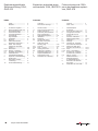
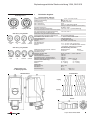
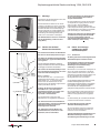
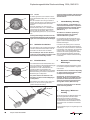
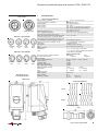
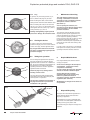
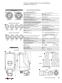
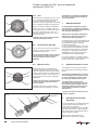
Explosionsgeschützte Steckvorrichtung 125A, 4- und 5-polig, GHG 519 Explosion-protected plugs and sockets 125A, 4-pole and 5-pole, GHG 519 Fiche et prise de 125A, à 4 pôles et 5 pôles, pour atmosphères explosives, GHG 519 GHG 519 45 GHG 519 75 Zone 2, Kat 3 (94/9/EG) Zone 2, cat 3 (94/9/EC) Zone 2, cat 3 (94/9/CE) Betriebsanleitung Operating instructions Mode d’emploi GHG 510 7004 P0001 D/E/F (D) Explosionsgeschützte Steckvorrichtung 125A, GHG 519 Explosion-protected plugs Fiches et prises de 125A and sockets 125A, GHG 519 pour atmosphères explosives, GHG 519 Inhalt: Contents: 1 1.1 2 3 4 5 6 6.1 6.2 6.3 6.3.1 6.3.2 6.4 6.5 7 8 9 10 Inhalt................................... Maßbild............................... 2 3 Technische Angaben........... Steckvorrichtung GHG 519. Sicherheitshinweise............. Normenkonformität............. Verwendungsbereich........... Verwendung/ Eigenschaften..................... Installation.......................... Montage............................. Öffnen des Gerätes/ Elektrischer Anschluss....... Kabel- und Leitungseinführung; Verschlussstopfen............................... Steckdosen........................ Stecker / Kupplung.............. Schließen des Gerätes........ Inbetriebnahme.................. Instandhaltung/Wartung Reparatur / Instandsetzung/ Änderungen........................ Entsorgung / Wiederverwertung......................... Konformitätserklärung........ 3 3 4 4 4 4-5 5 5 1 1.1 2 3 4 5 6 6.1 6.2 5 6.3 5-6 5-6 6 6 6 6 6.3.1 6.3.2 6.4 6.5 7 8 9 10 6 6 15 Contenu: Contents.............................. Dimensional drawings.......... 2 7 Technical data...................... Plug and socket GHG 519.... Safety instructions................ Conformity with standards... Field of application................ Application/Properties........... Installation............................ Mounting.............................. Opening the device / Electrical connection............. Cable entry (KLE); blanking plug........................ Sockets................................ Plug / Coupler...................... Closing the device................ Putting into operation............ Maintenance/Servicing......... Repairs/Modifications.......... Disposal/Recycling.............. Declaration of conformity..... 7 7 8 8 8 8-9 9 9 9 9-10 9-10 10 10 10 10 10 10 15 Contenu............................... Plans cotés.......................... 1 1.1 2 3 4 5 6 6.1 6.2 6.3 6.3.1 6.3.2 6.4 6.5 7 8 9 10 2 Cooper Crouse-Hinds GmbH Caractéristiques techniques........................... Fiches et prises GHG 519.... Consignes de sécurité.......... Conformité avec les normes................................. Domaine d’utilisation............ Utilisation/Propriétés............ Installation............................ Montage............................... Ouverture de l’appareil/ Raccordement électrique...... Entrées de câble (KLE) bouchons de fermeture......... Prise...................................... Fiche / Prolongateur.............. Fermeture de l’appareil/ Fermeture du couvercle........ Mise en service.................... Maintien/Entretien................ Réparation/Remise en état/Modifications............ Évacuation des déchets/ Recyclage............................. Déclaration de conformité.... 2 11 11 11 12 12 12 12-13 13 13 13 13-14 13-14 14 14 14 14 14 14 15 Explosionsgeschützte Steckvorrichtung 125A, GHG 519 1 Kodierung Zone 2 Technische Angaben 1.1 Steckvorrichtung GHG 519 Gerätekennzeichnung nach 94/9/EG: EG-Baumusterprüfung: Nennspannung: Max. Nennstrom: Max. Vorsicherung: 3-polig + PE 3-polig +N + PE II 3 G Ex nC IIC T5/T6 PTB 99 ATEX 1115 bis 690 V, 50/60 Hz 125 A 125 A gL ohne therm. Schutz 160 A gL mit therm. Schutz (auf 125A eingestellt) bis 690 V /125A -20° C bis +40° C (Listenausführung) Schaltvermögen AC 3: Zulässige Umgebungstemperatur: Abweichende Temperaturen sind bei Sonderversionen möglich) GHG 519, 4-polig 50/60Hz 220-250V blau 380-415V 500V rot schwarz 690V schwarz GHG 519, 5-polig 50/60Hz 220-250V blau 380-415V 500V rot schwarz 690V schwarz Maßangaben in mm X = Befestigungsmaße Zul. Lagertemperatur in Originalverpackung: Schutzart nach EN/IEC 60529 bei geschlossenem und gesichertem Klappdeckel sowie ordnungsgemäß gesteckten Kombinationen: Schutzklasse nach EN/IEC 61140: Leitungseinführung: Wandsteckdose Stecker Anschlussklemme: Wandsteckdose Stecker Mindestanschlussquerschnitt / Klemme: bei 125A Nennstrom Prüfdrehmomente: Hutmutter der KLE M63 Deckelschrauben Anschlussklemmen, Stecker Anschlussklemmen, Wandsteckdose Selbstschneidende Schrauben Größe 5 Gewicht: (Listenausführung): Wandsteckdose Stecker Hilfskontakt: Nennspannung: Nennstrom: Schaltvermögen: -40° C bis +80° C IP 66 (Listenausführung) I - wird von den Geräten erfüllt (Listenausführung) 2 x M63 (Ø35-46 mm) Ø 21-48mm (Ø 31-58 mm) 2 x 4 - 70 mm² (max 1x120 mm²)* 1 x 4 - 35 mm² mit Stiftkabelschuh 1x50mm² * (mitgelieferte Kabelschuhe verwenden Strombelastung beachten ! Wandsteckdose Stecker 1x 50 mm² 1 x 35 mm² Ø min. 22,0 Nm / Ø max. 5,00 Nm 2,50 Nm 4,50 Nm 6,00 Nm 3,00 Nm (Seite 6, Pos. 5) 4-polig 5 polig ca. 12,30 kg ca. 13,00 kg ca. 0,90 kg ca. 1,20 kg 690 V VAC 20 A AC 15 DC 13 Wandsteckdose 400V / 6 A 24V / 2 A Anschlussbild 4-polig 5-polig ohne Hilfskontakt mit Hilfskontakt Stecker Cooper Crouse-Hinds GmbH 3 Explosionsgeschützte Steckvorrichtung 125A, GHG 519 2 Sicherheitshinweise Die Steckvorrichtungen GHG 519 sind nicht für Zone 0 und Zone 1 geeignet. Die auf den Geräten angegebene Temperaturklasse und Zündschutzart ist zu beachten. Für die Einhaltung der auf dem Typschild des Betriebsmittels angegebenen Temperaturklasse ist die zulässige Umgebungstemperatur, der Anschlussquerschnitt, sowie die, maßgeblich durch die Verlustleistung bedingte Eigenerwärmung des Betriebsmittels zu beachten (Prüfkriterium für die Eigenerwärmung ist eine Überlastung um 10%). Vor Öffnen der Gehäuse Spannungsfreiheit sicherstellen bzw. geignete Schutzmaßnahmen ergreifen. Umbauten oder Veränderungen an den Steckvorrichtungen sind nicht gestattet. Sie sind bestimmungsgemäß in unbeschädigtem und einwandfreiem Zustand zu betreiben. Als Ersatz und zur Reparatur dürfen nur Originalteile von CEAG verwendet werden. Reparaturen, die den Explosionsschutz betreffen, dürfen nur von CEAG oder einer qualifizierten Elektrofachkraft in Übereinstimmung mit national geltenden Regeln durchgeführt werden. Vor Inbetriebnahme müssen die Steckvorrichtungen entsprechend der im Abschnitt 6 genannten Anweisung geprüft werden. Die Steckvorrichtungen nur mit den zugehörigen unbeschädigten CEAG Steckern betreiben. Die Stecker GHG 519 dürfen nur in den Wandsteckdosen der Serien GHG 519 .. und GHG 525 .. benutzt werden. Die Stecker dürfen auch in allen CEE Industriesteckvorrichtungen der Serie I betrieben werden. Steckdoseneinsatz und Betätigungsschalter sind mechanisch so miteinander verriegelt, dass eine Inbetriebnahme (Einschalten) nur bei gestecktem Stecker möglich ist. Alle Fremdkörper müssen vor der ersten Inbetriebnahme aus den Geräten entfernt werden. Beachten Sie die nationalen Sicherheitsund Unfallverhütungsvorschriften und die nachfolgenden Sicherheitshinweise in dieser Betriebsanleitung, die wie dieser Text in Kursivschrift gefasst sind! 4 Cooper Crouse-Hinds GmbH 3 Normenkonformität Das Betriebsmittel ist gemäß DIN EN ISO 9001 entwickelt, gefertigt und geprüft worden. Es entspricht den in der Konformitätserklärung aufgeführten Normen. 94/9 EG: Geräte und Schutzsysteme zur bestimmungsgemäßen Verwendung in explosionsgefährdeten Bereichen. Weitere Anforderungen wie die EG Richtlinie Elektromagnetische Verträglichkeit (2004/108/ EG) werden von den Betriebsmitteln erfüllt. Das Stecken und Trennen des Steckers von der Steckdose ist nur im ausgeschalteten Zustand möglich. Zum Einschalten der Steckdose ist der Stecker bis zum Anschlag einzustecken. Um die Schutzart gem. Typenschild auch mit gestecktem Stecker zu erreichen, wird der Bajonettring des Steckers, Seite 5, Bild 2, Pos 2, bis zum Anschlag auf die Steckdose gedreht. Danach kann der Betätigungsschalter am Schaltknebel, Seite 5, Bild 1, Pos 7, eingeschaltet werden. Dabei wird der Stecker in der Steckdose verriegelt. Zum Ausschalten und Ziehen des Steckers ist in umgekehrter Reihenfolge vorzugehen. 4 Verwendungsbereich Die Steckvorrichtungen GHG 519 sind zum Einsatz in explosionsgefährdeten Bereichen der Zonen 2 gemäß IEC 60079-10 geeignet! Die eingesetzten Gehäusematerialien einschließlich der aussenliegenden Metallteile bestehen aus hochwertigen Werkstoffen, die einen anwendungsgerechten Korrosionsschutz und Chemikalienresistenz in "normaler Industrieatmosphäre" gewährleisten: - schlagfestes Polyamid - glasfaserverstärktes Polyester - Edelstahl AISI 316 L. Bei einem Einsatz in extrem aggressiver Atmosphäre, können Sie zusätzliche Informationen über die Chemikalienbeständigkeit der eingesetzten Kunststoffe, bei Ihrer zuständigen Cooper Crouse-Hinds Niederlassung erfragen. 5 Verwendung/Eigenschaften Die Steckvorrichtungen GHG 519 dienen zur Stromversorgung von standortvariablen VorOrt- Steuerungen, elektrischen Anlagen sowie von beweglichen Maschinen und Antrieben in explosionsgefährdeten Bereichen. Die Steckvorrichtungen sind auch im "normalen Industriebereich" verwendbar. Die Steckvorrichtungen für Niederspannungen GHG 519 sind mit einem Lasttrennschalter ausgestattet und sind bis max. 125A einsetzbar (siehe technische Daten). Die Steckvorrichtungen sind generell für den in der IEC 309 festgelegten Spannungsbereich einsetzbar (z.B. UN 400V das entspricht dem Spannungsbereich 380 - 415V). Das am Stecker angeschlossene Betriebsmittel muss für die anliegende Netzspannung geeignet sein. Nach dem Trennen des Steckers von der Steckdose ist die Steckdose mit dem Klappdeckel zu schließen und mit dem Bajonettring, Seite 5, Bild 1 + 2, Pos 9, zu sichern. Angaben aus Punkt 3 und 4 sind bei der Verwendung zu berücksichtigen. Andere als die beschriebenen Anwendungen sind ohne schriftliche Erklärung der Fa. CEAG nicht zulässig. Beim Betrieb sind die in der Betriebsanleitung unter Punkt 7 genannten Anweisungen zu beachten. Die Funktion der Verriegelung zum Schutz vor unsachgemäßer Verwendung z.B. von Industriesteckern in der Zone 2, ist, wie unter Punkt 7 Instandhaltung / Wartung beschrieben, von Zeit zu Zeit zu überprüfen. Die Stecker sind im Freien mit der Steckeröffnung (Stiftseite) nach unten aufzubewahren bzw. mit optional erhältlichen Steckerschutzkappen (siehe Hauptkatalog) zu verschließen. Die Verantwortung hinsichtlich bestimmungsgemäßer Verwendung dieser Steckvorrichtung unter Bezugnahme der in der Anlage vorhandenen Rahmenbedingungen (s. technische Daten) liegt allein beim Betreiber. Nach einem Kurzschluss im Stromkreis ist die Funktionsfähigkeit der Steckvorrichtung und der Stecker zu überprüfen. Da die Schaltkontakte wegen der druckfesten Kapselung nicht mehr prüfbar sind, muss nach mehrmaligen Kurzschlüssen der komplette Schalteinsatz ausgetauscht werden. 6 Installation Für das Errichten / Betreiben sind die relevanten nationalen Vorschriften sowie die allgemein anerkannten Regeln der Technik maßgebend. Explosionsgeschützte Steckvorrichtung 125A, GHG 519 6.1 Bild 1 Montage Die Montage der Wandsteckdosen kann ohne Öffnen des Gehäuses erfolgen. Die Wandsteckdosen dürfen bei der Direktmontage an der Wand nur an den vorgesehenen Befestigungspunkten eben aufliegen. Die gewählte Schraube muss der Befestigungsöffnung angepasst sein (siehe Maßbild) und sie darf die Öffnung nicht beschädigen (z.B. Verwendung einer Unterlegscheibe). Das Gerät ist mit 4 Schrauben zu befestigen. 7 Die Wandsteckdosen sind so zu montieren, daß die Stecköffnung nicht nach oben zeigt (Bild 2). 9 6.2 Bild 2 Öffnen des Gerätes / Elektrischer Anschluss Der elektrische Anschluss des Betriebsmittels darf nur durch Fachpersonal erfolgen. 7 9 Vor Öffnen der Gehäuse Spannungsfreiheit sicherstellen bzw. geignete Schutzmaßnahmen ergreifen. Die ordnungsgemäß abisolierten Anschlussleitungen der Kabel sind unter Berücksichtigung einschlägiger Vorschriften anzuschließen. Die Isolation der Anschlussleitungen muss bis an die Klemme heranreichen. Der Leiter selbst darf nicht beschädigt sein. 8 Bild 3 + 4, Seite 6: Der Steckereinsatz, Pos. 3, ist durch Lösen der Befestigungsschrauben, Pos. 5, aus der Steckerhülse, Pos. 11, herauszunehmen. Danach kann der Steckereinsatz an den Anschlüssen der Steckerstifte angeschlossen werden (siehe Bild 5, Seite 6). 3 2 6 4 5 7 Achtung: Bei Verlust der Befestigungsschrauben Pos. 5, sind diese durch gleichartige Schrauben zu ersetzen oder direkt vom Hersteller anzufordern. Typ Größe 5 =KTG 50x50/25. Der Zusammenbau erfolgt nach dem Kabelanschluss in umgekehrter Reihenfolge. Die minimal und maximal anschließbaren Leiterquerschnitte sowie die erforderlichen Mindestquerschnitte für die Strombelastung sind zu beachten. 9 Alle Schrauben und/oder Muttern der Anschlussklemmen, auch die der nicht benutzten, sind fest anzuziehen. Zur Aufrechterhaltung der Zündschutzart ist der Leiteranschluss mit besonderer Sorgfalt durchzuführen. Die Anschlussklemmen sind für den Anschluss von Kupferleitern ausgelegt. Bei der Verwendung von mehr- oder feindrähtigen Anschlusskabel /-leitungen sind die Aderenden entsprechend den geltenden nationalen und internationalen Vorschriften zu behandeln (z.B. Verwendung von Aderendhülsen). Achtung: Das Aufpressen der Kabelschuhe auf das Kabel ist fachgemäß durchzuführen. Es ist sicherzustellen, dass die erforderlichen Mindestluftstrecken eingehalten werden (bei 690V >12mm). 6.3 Kabel- und Leitungseinführungen (KLE); Verschlussstopfen 6.3.1 Steckdosen Es dürfen generell nur bescheinigte KLE und Verschlußssstopfen verwendet werden. Für bewegliche Leitungen sind Trompetenverschraubungen oder andere geeignete Einführungen mit zusätzlicher Zugentlastung zu verwenden. Beim Einsatz von KLE mit einer niedrigeren als der für das Gerät zutreffenden IP-Schutzart, (siehe technische Daten, Seite 3) wird die IPSchutzart des gesamten Gerätes reduziert. Die für die eingesetzten KLE maßgebenden Montagerichtlinien sind zu beachten. Um die Mindestschutzart herzustellen, sind nicht benutzte Einführungsöffnungen mit einem bescheinigten Verschlussstopfen zu verschließen. Es ist darauf zu achten, daß bei der Installation der KLE die für den Leitungsdurchmesser geeigneten Dichtungseinsätze verwendet werden. Bei ausschneidbaren Dichtungseinsätzen ist sicherzustellen,dass der Einsatz ordnungsgemäß dem Leitungsdurchmesser angepasst wird. Zur Sicherstellung der erforderlichen Mindestschutzart sind die KLE fest anzuziehen. Bei übermäßigem Anziehen kann die Schutzart beeinträchtigt werden. Alle nicht benutzten metrischen CEAG KLE sind mit dem bescheinigten Verschluss für metrische KLE zu verschließen. Achtung: Metallflansche, Metallplatten und Metallverschraubungen müssen in den Potentialausgleich miteinbezogen werden. Cooper Crouse-Hinds GmbH 5 Explosionsgeschützte Steckvorrichtung 125A, GHG 519 6.3.2 Bild 3 3 2 5 5 Stecker Es dürfen generell nur die im Stecker vorhandenen Dichteinsätze Bild 6, Pos 12, verwendet werden. Bei der Installation der Leitung ist darauf zu achten, dass die für den Leitungsdurchmesser geeigneten Dichtungseinsätze verwendet werden. Nach der Installation der Leitung ist die Überwurfmutter, Bild 6, Pos. 4 handfest bis zur Erzielung der Dichtwirkung anzuziehen. Danach sind die Schrauben, Bild 6, Pos. 5, der Zugentlastung Bild 6, Pos. 6, fest anzuziehen. Achtung! Übermäßiges Anziehen kann die Zugentlastungswirkung negativ beeinträchtigen bzw. das Anschlusskabel beschädigen. Bild 4 2 11 6.4 Schließen des Gerätes L2 L3 L1 N 3 PE Vor Öffnen des Gehäuses Spannungsfreiheit sicherstellen oder geeignete Schutzmaßnahmen ergreifen. Die erforderlichen Wartungsintervalle sind anwendungsspezifisch und daher in Abhängigkeit von den Einsatzbedingungen vom Betreiber festzulegen. 8 Inbetriebnahme Vor Inbetriebnahme des Betriebsmittels sind die in den einzelnen nationalen Bestimmungen genannten Prüfungen durchzuführen. Außerdem ist vor der Inbetriebnahme die korrekte Funktion und Installation des Betriebsmittels in Übereinstimmung mit dieser Betriebsanleitung und anderen anwendbaren Bestimmungen zu überprüfen. Vor jedem Stecken des Steckers in die Steckdose ist dieser auf Beschädigungen zu überprüfen. Reparatur / Instandsetzung / Änderungen Instandsetzungsarbeiten/Reparaturen dürfen nur mit CEAG Originalersatzteilen vorgenommen werden. Bei Schäden an der druckfesten Kapselung ist das betroffene Betriebsmittel an CEAG zur Reparatur zurückzugeben. Reparaturen, die den Explosionsschutz betreffen, dürfen nur von CEAG oder einer qualifizierten Elektrofachkraft in Übereinstimmung mit national geltenden Regeln durchgeführt werden (EN 60079-19). Umbauten oder Änderungen am Betriebsmittel sind nicht gestattet. 6 9 11 5 4 3 Die für die Wartung / Instandhaltung von elektrischen Betriebsmitteln in explosionsgefährdeten Bereichen geltenden nationalen Bestimmungen sind einzuhalten (EN 60079-17). 6.5 12 2 Instandhaltung / Wartung Alle Fremdkörper sind aus dem Gerät zu entfernen. Bei übermäßigem Anziehen kann die Schutzart beeinträchtigt werden. Der Betreiber muss dafür sorgen, dass beim Betrieb der Steckvorrichtung überall ein gleiches Erdpotential anliegt. Bild 6 7 Im Rahmen der Wartung sind vor allem die Teile, von denen die Zündschutzart abhängt, zu prüfen (z.B. Unversehrtheit der druckfesten Komponenten, des Gehäuses, der Dichtungen und der Kabel- und Leitungseinführung). Sollte bei einer Wartung festgestellt werden, dass Instandsetzungsarbeiten erforderlich sind, ist Abschnitt 8 dieser Betriebsanleitung zu beachten Zur Sicherstellung der erforderlichen Mindestschutzart sind die Deckelschrauben und die Schrauben der Stecker fest anzuziehen. Bild 5 Unsachgemäße Installation und Betrieb der Steckvorrichtungen kann zum Verlust der Garantie führen. Entsorgung / Wiederverwertung Bei der Entsorgung des Betriebsmittels sind die jeweils geltenden nationalen Abfallbeseitigungsvorschriften zu beachten. Zur Erleichterung der Wiederverwertbarkeit von Einzelteilen sind Kunststoffteile mit dem Kennzeichen des verwendeten Kunststoffes versehen. Programmänderungen und -ergänzungen sind vorbehalten. 6 Cooper Crouse-Hinds GmbH Explosion-protected plugs and sockets 125A, GHG 519 1 Code Zone 2 Technical data 1.1 Plug and socket GHG 519 Marking acc. to 94/9/EC: EC type examination certificate: Rated voltage: Rated current: Back-up fuse: II 3 G Ex nC IIC T5/T6 PTB 99 ATEX 1115 up to 690 V, 50/60 Hz max. 125 A max. 125 A gL without thermal protection max. 160 A gL with thermal protection (therm. protection set to 125A) 3-pole + PE 3-pole +N + PE Switching capacity AC 3: Perm. ambient temperature: up to 690 V / 125 A -20° C to +40° C (standard version) Other temperatures possible for special versions. GHG 519, 4-pole 50/60Hz 220-250V blue 380-415V red 500V black 690V black Perm. storage temperature in original packing: Protection category acc. to EN/IEC 60529 with closed and secured hinged cover as well as combinations properly plugged together Insulation class acc. to EN/IEC 61140: Cable entry: Wall socket Plug Supply terminal: Wall socket Plug GHG 519, 5-pole 50/60Hz 220-250V blue 380-415V red 500V black Dimensions in mm X = fixing dimensions 690V black Min. cross section / Supply terminal for 125A rated current Test torques: Cap nut of the M63 entry Cover screws Terminals, plug Terminals, wall socket Self-cutting screws size 5 Weight (standard version): Wall socket Plug Auxiliary contact: Rated voltage: Rated current: Switching capacity: -40° C to +80° C IP 66 (standard version) I - is complied with by devices (standard version) 2 x M63 (Ø 35 - 46 mm) Ø 21-48 mm (Ø 31-58 mm) 2 x 4 - 70 mm² (max 1x120 mm²)* 1 x 4 - 35 mm² with pin cable lugs 1x50mm² * (use cable lugs supplied) Observe current load ! Wall socket Plug 1x 50mm² 1x 35mm² Ø min. 22.0 Nm / Ø max. 5.00 Nm 2.5 Nm 4.5 Nm 6.0 Nm 3.0 Nm 4-pole 5-pole ca. 12.30 kg ca. 13.00 kg ca. 0.90 kg ca. 1.20 kg 690 V VAC 20 A AC 15 DC 13 400V / 6 A 24V / 2 A Wall socket Contact arrangement 4-pole 5-pole w/o auxiliary contact with auxiliary contact Plug Cooper Crouse-Hinds GmbH 7 Explosion-protected plugs and sockets 125A, GHG 519 2 Safety instructions The GHG 519 plugs and sockets are not suitable for Zone 0 and Zone 1 hazardous areas. The temperature class and explosion group marked on the apparatus shall be observed. To ensure adherence to the temperature class stated on the type label of the apparatus, the permissible ambient temperature, the rated terminal cross section and the self-heating of the apparatus, that is mainly due to the power dissipation, shall be taken into account (test criterion for the selfheating is an overload of 10%). Before opening the apparatus, ensure that it has been isolated from the voltage supply, or take appropriate protective measures. Modifications or changes to the plugs and sockets are not permitted. They shall be used for their intended purpose and in a perfect and clean condition. Only original CEAG parts may be used as replacements and for repairs. Repairs that affect the explosion protection, may only be carried out by CEAG or a qualified electrician in compliance with the respective national regulations. Prior to being put into operation, the plug and socket shall be checked in accordance with the instructions in section 6. The sockets may only be used with the associated CEAG plugs in an undamaged condition. The plugs type GHG 519 .. shall only be used in wall sockets of the series GHG 519 ... and GHG 525 ... . The plugs may also be used in any Series 1 IEC industrial socket outlets. The socket insert and the actuating switch are mechanically interlocked in such a way that operation (switching on) is only possible when the plug is inserted. Before initial operation, any foreign matter shall be removed from the the plugs and sockets. The national safety rules and regulations for the prevention of accidents, as well as the safety instructions included in these operating instructions, that, like this text, are set in italics, shall be observed! 8 Cooper Crouse-Hinds GmbH 3 Conformity with standards The apparat is conform to the standards specified in the EC-Declaration of conformity. It has been designed, manufactured and tested according to the state of the art and to DIN EN ISO 9001. 94/9 EC: Equipment and protective systems intended for use in potentially explosive atmospheres. The apparats fulfil further requirements, such as the EC directive on electromagnetic compatibility (2004/108/EEC) 4 Field of application The plugs and sockets GHG 519 are suitable for use in 2 hazardous areas acc. to IEC 60079-10! The enclosure materials employed, including the exterior metal parts, are made of highquality materials which ensure a corrosion protection and resistance to chemical substances corresponding to the requirements in a “normal industrial atmosphere”: - impact resistant polyamide - glass-fibre reinforced polyester - special steel AISI 316 L In case of use in an extremely aggresive atmosphere, please refer to manufacturer. The plug can only be inserted or withdrawn when no voltage is applied. The socket can only be switched on if the plug is fully inserted. In order to guarantee the type of protection stated on the type label, also when the plug has been inserted, the bayonet ring of the plug, page 9, Fig. 2. Item 2, has to be turned until it reaches the stop on the socket. To switch off and withdraw the plug, proceed in the reverse order. After withdrawing the plug from the socket, seal the socket with the hinged cover and secure it with the bayonet ring, page 9, Figs. 1 and 2, Item 9. The data according to sections 3 and 4 shall be taken into account during use. Applications other than those described are not permissible without a written declaration of consent from Messrs. CEAG. During operation the instructions given in section 7 of the operating instructions shall be observed. From time to time it is necessary to check the functioning of the interlock that acts as a protection against incorrect use, e.g. of industrial plugs in Zone 2. See section 7, Maintenance / Servicing. When used in open air installations, the plugs must be kept with the plug opening (pin end) facing downwards or be sealed with protective plug caps that are available as an optional extra (see main catalogue). The sole responsibility with respect to the suitability and proper use of the plugs and sockets with regard to the basic requirements of these instructions (see technical data) lies with the operator. 5 Use/Properties The GHG 519 plugs and sockets are used for the power supply of local controls with varying locations, as well as of electrical installations, mobile machinery and driving gear in hazardous areas. The plugs and sockets can also be used in a „normal industrial area“. The low-voltage plugs and sockets GHG 519 are fitted with a load break switch and can be used up to max. 125A (see technical data). The plugs and sockets can generally be used for the voltage range laid down in IEC 309 (e.g. UN 400V that corresponds to the voltage range 380-415V). The apparatus connected to the plug shall be suitable for the applied mains voltage. After a short in the circuit, the functioning of the plug and socket shall be checked. As, due to the flameproof encapsulation, it is not possible to check the switch contacts, the complete switch insert has to be replaced after repeated short circuits. 6 Installation The relevant national regulations and the generally recognized rules of engineering apply for the installation and operation. Explosion-protected plugs and sockets 125A, GHG 519 6.1 Fig. 1 Mounting The wall sockets can be mounted without opening the enclosure. When wall sockets are mounted directly onto the wall, they shall rest evenly only at the respective fastening points. The chosen screw shall match the fastening hole (see dimensional drawing) and it must not damage the hole (e. g. use of a washer). The device shall be fastened diagonally with at least 2 screws. 7 The wall-mounting shall be mounted in such a way that the plug opening does not face upwards (Fig. 2). 9 6.2 Opening the device/ Electrical connection The electrical connection of the device may only be carried out by skilled staff. Fig. 2 7 9 Before opening the apparatus, ensure that it has been isolated from the voltage supply, or take appropriate protective measures. Taking into account the respective regulations, the properly bared conductors of the cables shall be connected. The correctly stripped wires of the cable shall be connected according to the relevant regulations. 8 Figs. 3 + 4, page 10 Undo the fixing screws, Item 5, to remove the plug insert, Item 3, from the plug sleeve, Item 11. The plug insert can then be connected to the plug pin connections (see Fig. 5, page 10). 3 2 6 4 5 7 9 Warning: If any fixing screws, Item 5, are lost, they shall be replaced by screws of the same type or ordered directly from the manufacturer. Type: Size 5 = KTG 50x50/25 The supply terminals are designed for the connection of copper conductors. If multi- or fine-wire connecting cables are used, the wire ends will have to be handled in acc. with the applicable national and international rules (e. g. use of sleeves for strands). Warning: The cable lugs shallbe crimped onto the cable in a workmanlike manner. It is to be ensured that the required min. air gaps are kept (at 690V >12mm). 6.3 Cable entries (KLE); blanking plugs 6.3.1 Socket Generally, only certified cable entries and blanking plugs are permitted for use. Flexible cables shall be used with trumpetshaped cable glands or other suitable entries with additional pull-relief. When using cable entries with a lower IP protection than that which applies to the device (see page 7, technical data), the IP protection of the whole device will be reduced. The mounting directives applicable to the cable entries used shall be observed. Unused holes shall be closed with a certified blanking plug in order to establish the minimum protection category. In case of sealing inserts that are cut to size, it shall be ensured that the insert is properly adapted to the cable diameter. Care has to be taken that, when fitting the cable entries, sealing inserts appropriate to the cable diameter are used. In order to ensure the required minimum protection category, the cable glands are to be tightened down. Overtightening might impair the protection category. After connecting the cable, proceed in the reverse order to reassemble plug. All unused metric CEAG cable entries shall be closed with the certified blanking plug for metric cable entries. The connectible min. and max. conductor cross-sections as well as the required minimum cross section for the current load shall be observed (see technical data). Attention: Metal flanges, metal plates and metal cable glands shall be included in the equipotential earth connection. All screws and/or nuts of the supply terminals, including the unused ones, shall be tightened down. The conductors shall be connected with special care in order to maintain the type of protection. Cooper Crouse-Hinds GmbH 9 Explosion-protected plugs and sockets 125A, GHG 519 6.3.2 Fig. 3 7 Plug In general, only the sealing inserts, Fig. 6, Item 12, fitted in the plug may be used. 3 When mounting the cable, ensure that the sealing inserts match the cable diameter used. 2 5 5 After connecting the cable, screw down the cap nut , Fig. 6, Item 4, by hand until it seals. Then tighten down the screws, Fig. 6, Item 5, of the pull-relief, Fig. 6, Item 6. Warning! Overtightening might impair the pull-relief or damage the connection cable. Fig. 4 6.4 2 11 Closing the device In order to ensure the required minimum protection category, the cover screws and the screws of the plug shall be tightened down. Any foreign matter shall be removed from the device overtightening might impair the protection category. 6.5 Fig. 5 L2 L3 L1 N 3 PE Bild 6 Taking into operation Check the plug for any damage before inserting it in the socket. The necessary intervals between servicing depend upon the specific application and shall be stipulated by the operator according to the respective operating conditions. During servicing, above all, the parts on which the explosion protection depends, (e.g. intactness of the flameproof components, the enclosure, the seals and cable entries), shall be checked. If, in the course of servicing, it is ascertained, that repairs are necessary, Section 8 of these operating instructions shall be observed. Repairs/Modifications Only original CEAG parts shall be used for carrying out repairs. In the event of damage to the flameproof encapsulation, replacement of these components is mandatory. In case of doubt, the respective apparatus shall to be returned to CEAG for repair. The user shall ensure that asequipotential earth applies throughout when the plug and socket system is in operation. The improper installation and operation of the plugs and sockets may result in the invalidation of the guarantee. Modifications or changes to the device are not permitted. 6 9 11 5 4 3 Prior to opening the enclosure, it is necessary to ensure that the voltage supply has been isolated or to take suitable protective measures. Repairs that affect the explosion protection. May only be carried out by CEAG or a qualified electrician in compliance with the applicable national regulations (IEC 60079-19). 12 2 The valid national regulations for the servicing / maintenance of electrical apparatus for use in potentially explosive atmospheres shall be observed (IEC 60079-17). 8 Prior to taking the apparatus into operation, the tests specified in the relevant national regulations shall be carried out. In addition to this, the correct functioning and installation of the apparatus in accordance with these operating instructions and other applicable regulations shall be checked. Maintenance/Servicing Disposal/Recycling The respective valid national regulations for waste disposal shall be observed when disposing of apparatus. To facilitate the recycling of individual parts, parts made of moulded plastic shall bear the marking for the type of plastic used. The product range is subject to changes and additions. 10 Cooper Crouse-Hinds GmbH Fiches et prises de 125A pour atmosphères explosives, GHG 519 1 Codage Zone 2 3 pôles + PE 3 pôles +N + PE Caractéristiques techniques 1.1 Fiche et prise, GHG 519 Marquage selon 94/9/CE: Attestation d’examen CE de type: Tension nominale: Courant nominal: Fusible maximal placé en amont: sans protection thermique avec protection thermique (réglée pour 125A) Puissance de coupure AC 3: Température ambiante admissible: II 3 G Ex nC IIC T5/T6 PTB 99 ATEX 1115 jusqu’à 690VCA, 50/60 Hz 125 A au maxi 125 A au maxi 160 A gL au maxi 690 V /125 A au maxi -20° C à +40° C (modèle de liste) (En cas de modèles spéciaux d’autres températures possibles) GHG 519, 4 pôles 50/60Hz 220-250V bleu 380-415V rouge 500V noir 690V noir GHG 519, 5 pôles 50/60Hz 220-250V bleu 380-415V rouge 500V noir Dimensions en mm X = dimensions de fixation 690V noir Température de stockage dans l’emballage original: Indice de protection selon EN/CEI 60529, avec le couvercle fermé et arrêté et les dispositifs dûment enfichés: Classe d’isolation selon EN/CEI 61140: Entrée de câble: Prise murale Fiche Borne de connexion: Prise murale Connexion de la fiche Diamètre de connexion minimale par borne: (pour un courant nominal de 125A -T6) Torques d'essai: Ecrou borgne de l’entrée de câble M50 Vis de couvercle Bornes de connexion, Fiche Bornes de connexion, Prise murale Vis auto-taraudeuse taille 5 Poids (modèle de liste): Prise murale Fiche Contact auxiliaire: tension nominale courant nominal puissance de coupure Prise murale -40° C à +80° C IP 66 (modèle de liste) I - est remplie par les dispositifs (modèle de liste) 2 x M63 (Ø35-46mm) + 1 x bouchon de fermeture M50 Ø 21-48mm (Ø 31-58mm) 2 x 4 - 70 mm² (max 1x120 mm²)* 1 x 4 - 35 mm² avec cosse à cheville 1x50mm² * (utiliser la cosse fournie) Prendre la valeur de tension en compte. Prise murale Fiche 1x 50mm² 1x 35mm² Ø min. 22,0 Nm / Ø maxi. 5,00 Nm 2,5 Nm 4,5 Nm 6,0 Nm 3,0 Nm (page 14, Pos.5) 4 pôles 5 pôles env. 12,30 kg env. 13,00 kg env. 0,90 kg env. 1,20 kg 690 V CA 20 A CA 15 CC 13 400 V / 6 A 24 V / 2 A Disposition des contacts 4 pôles 5 pôles sans contact auxiliaire avec contact auxiliaire Fiche Cooper Crouse-Hinds GmbH 11 Fiches et prises de 125A pour atmosphères explosives, GHG 519 2 Consignes de sécurité Les fiches et prises du type GHG 519 pour atmosphère explosive ne sont pas appropriées pour une emploi en Zone 0 et 1 Le groupe d’explosion et la classe de température indiqués sur les appareils devront être respectés. Afin de respecter la classe de température indiquée sur l’étiquette du type de l’appareil, on prendra en compte la température ambiante, le diamètre de connexion ainsi que les pertes d’énergie occasionnées par l’échauffement propre de l’appareil (le critère de contrôle limite pour l’échauffement est une surcharge de 10%). Avant ouverture de l’enveloppe, mettre l’appareil hors-tension et prendre les mesures préventives appropriées. Il n’est pas admis de transformer ou de modifier les fiches et prises. Elles ne doivent être employées que pour la fonction qui leur est dévolue et ce,en parfait état de propreté et de fonctionnement. Seules des pièces de rechange homologuées d’origine CEAG devront être utilisées comme remplacement et pour des réparations. Des réparations qui portent sur la protection contre l’explosion, ne devront être exécutées que par CEAG ou par un électricien qualifié en conformité avec la règlementation nationale en vigueur. Avant leur mise en service, les fiches et prises doivent être vérifiées selon l’instruction donnée dans la section 6. Les prises ne doivent être utilisées qu’avec les fiches CEAG correspondantes et en parfait état. Les fiches GHG 519 .. ne doivent être branchées que dans les prises murale des séries GHG 519 ... et GHG 525 ... . Les fiches peuvent également être branchées dans tous les socles industriels CEI. La pièce d’espacement et l’interrupteur sont verrouillés mécaniquement de telle sorte qu’une mise en service (mise sous tension) n’est possible que lorsque la prise est connectée. Avant la première mise en service, tout corps étranger doit être ôté des appareils. Respectez les prescriptions nationales de sécurité et de prévoyance contre les accidents ainsi que les consignes de sécurité qui suivent dans ce mode d’emploi en italique. 12 Cooper Crouse-Hinds GmbH 3 Conformité avec les normes Les boîtes à bornes ont été conçues, fabriquées et contrôlées suivant DIN EN ISO 9001. Les boîtes à bornes sont conformes aux normes reprises dans la déclaration de conformité 94/9 CE: Appareils et systèmes de protection destinés à être utilisés en atmosphère explosible. De Appareils de commande répondent à d’autres exigences comme par exemple, celles de la directive CE “Compatibilité électromagnétique” (2004/108/CEE). 4 Domaine d’utilisation Les fiches et prises du type GHG 519 conviennent à l’emploi en les zones 2 d’une atmosphère explosive selon CEI 60079-10. Pour l’enveloppe, les pièces métalliques extérieures, des matières de qualité supérieure ont été employées qui assurent une protection appropriée contre la corrosion et une résistance contre des agents chimiques en “atmosphère industrielle normale”: - polyamide résistant au choc - polyester renforcé par fibre de verre - acier spécial AISI 316 En cas d‘utilisation en atmosphère extrèmement corrosive, vous pouvez obtenir des informations complémentaires sur la résistance chimique des plastiques utilisés chez la succursale Cooper Crouse-Hinds de votre région. 5 Utilisation/Propriétés Les fiches et prises GHG 519 servent à l’alimentation en courant de réglages automatiques en place à emplacement variable et d’installations électriques ainsi que de machines et de mécanis-mes de commande mobiles en atmosphère explosive. Les fiches et prises peuvent aussi être employées en „atmosphère industrielle normale“. Les fiches et prises GHG 519 pour basses tensions sont dotées d’un sectionneur à coupure en charge et peuvent être exploitées jusqu’à 125A maxi (voir Caractéristiques techniques). Les prises et fiches sont utilisables dans les fourchettes de tension comprises de la norme CEI 309 (par exemple, UN 400 V appartient à la fourchette 380 - 415 V). L’ appareil connecté à la fiche doit être adapté à la tension du réseau correspondant. La fiche ne peut être enfichée dans la prise ou retirée de celle-ci que lorsque la prise est mise hors circuit. Pour la mise en circuit de la prise, la fiche doit y être enfichée jusqu’en butée. L'anneau à baïonnette de la fiche doit également être tourné jusqu'en butée afin d'assurer le mode de protection selon la plaque signalétique, (voir page 13, fig.2, pos. 2). Puis, l’interrupteur de verrouillage doit être déclenché, page 13, fig. 1, pos. 7, afin de bloquer la fiche dans la prise. Pour la mise hors circuit de la prise et pour retirer la fiche, procédez dans l’ordre inverse. Après avoir séparé la fiche de la prise, celle-ci est fermée avec le couvercle à charnière et bloquée avec l’anneau à baïonnette. Pour l’emploi, les consignes des sections 3 et 4 devront être respectées. Des emplois autres que ceux décrits ne sont admis qu’avec le consentement par écrit de la part de CEAG. Lors de l’exploitation, les instructions selon point 7 de ce mode d’emploi doivent être respectées. De temps en temps, la fonction de bloquage par ex. des fiches industrielles qui sert de protection contre l’emploi non convenable en zone 2, doit être vérifiée. En plein air, les fiches doivent être gardées avec leur ouverture (côté des broches) vers le bas. En option, elles peuvent être fermées avec les capuchons protecteurs pour la fiche qui sont disponibles sur demande (voir catalogue général). Seul l’utilisateur est responsable de l’emploi comme prévu de cette fiche et prise, en tenant compte des conditions générales existant dans l’établissement (voir Caractéristiques techniques). Après un court-circuit dans le circuit, le fonctionnement de la prise et de la fiche doit être vérifié. Etant donné que les contacts de commutation ne peuvent plus être vérifiés en raison de l’enveloppe antidéflagrante, l’insert de commutation complet devra être remplacé après des courts-circuits répétés. 6 Installation Pour l’installation et l’exploitation d’appareils électriques pour atmosphère explosive, la règlementation nationale en vigueur ainsi que les règles de la technique généralement reconnues devront être respectées. Fiches et prises de 125A pour atmosphères explosives, GHG 519 6.1 Fig. 1 Montage Le montage des prises murales peut se faire sans ouvrir l’enveloppe. En cas de montage directement au mur, les prises murales ne doivent reposer au niveau du mur que sur les points de fixation prévus. La vis choisie doit correspondre au trou de fixation (voir plan coté) et elle ne doit pas avarier l’ouverture (par ex. emploi d’une rondelle). Le dispositif doit être fixé en diagonale avec au moins deux vis. 7 Le montage de la prise murale doit se faire de sorte que l’ouverture d’enfichage ne soit pas dirigée vers le haut. (fig. 2). 9 6.2 Ouvertur e du dispositif/ Ouverture Raccor dement électrique Raccordement Le raccordement électrique du dispositif ne doit se faire que par du personnel qualifié. Fig. 2 7 Avant ouverture de l’enveloppe, mettre l’appareil hors-tension et prendre les mesures préventives appropriées. En tenant compte des règlements respectifs, les conducteurs dûment dénudés des câbles sont raccordés. 9 8 L’isolation doit couvrir le conducteur jusqu’à la borne. Le conducteur lui-même ne doit pas être endommagé. Fig. 3 + 4, page 14 Les vis de fixation, pos. 5, de l’insert de la fiche, pos. 3, sont desserrées pour le sortir de l’alvéole, pos. 11. Puis, l’insert peut être raccordé aux connexions des contacts mâles voir fig. 5, page 14. 3 2 6 4 5 7 9 Attention: En cas de perte des vis de fixation, pos. 10, celles-ci doivent être remplacées par des vis similaires ou être demandées au fabricant. Type taille 5 = KTG 50x50/25 . Après le raccordement du câble, le montage se fait dans l’ordre inverse Les sections minimales et maximales admissibles des conducteurs ainsi que les sections minimales requises pour la charge de courant doivent être respectées (voir caractéristiques techniques). Les bornes sont prévues pour le raccordement de conducteurs en cuivre. En cas d’utiliser des câbles de connexion multifilaires ou à fils de faible diamètre, les bouts de fil doivent être traités selon la règlementation nationale et internationale y applicable (par ex. emploi des embouts). Attention: Les cosses de câble doivent être emmanchées par pression sur le câble de manière appropriée. Il faut assurer que les entrefers minimaux requis soient respectés (à 690V >12mm). 6.3 Entrées de câble (KLE); bouchons de fermeture 6.3.1 Prise Généralement, seuls des bouchons de fermeture et des entrées de câble certifiés peuvent être utilisés. Pour des câbles flexibles il faudra utiliser des presses-étoupes à trompette ou d’autres entrées convenables avec décharge de traction supplémentaire. Lorsque des entrées de câble avec un indice de protection IP inférieur à celui du dispositif sont employées (voir page 11), l’indice de protection IP de l’ensemble sera réduit. Les directives pour le montage applicables aux entrées de câble montées doivent être respectées. Des ouvertures d’entrée non utilisées doivent être fermées avec un bouchon de fermeture certifié pour établir l’indice de protection minimum. Lors du montage des entrées de câble il faudra veiller à ce que des garnitures d’étanchéité correspondant au diamètre du câble soient utilisées. Si des garnitures doivent être coupées sur mesure, il faudra faire attention à ce que la garniture soit adaptée au diamètre du câble. Les entrées de câble doivent être serrées à fond pour maintenir l’indice de protection minimum. Au cas où elles seraient forcées, cela pourrait être nuisible à l’indice de protection. Toutes les vis et/ou écrous des bornes de connexion, aussi celles des bornes non utilisées, doivent être serrées à fond. Toutes les entrées de câble métriques CEAG non utilisées doivent être fermées avec un bouchon de fermeture certifié pour des entrées de câble métriques. Afin de maintenir le mode de protection contre l’explosion, le raccordement des conducteurs doit se faire très soigneusement. Attention: les plaques à brides métalliques, les plaques de fond métalliques et les presse-étoupe métalliques doivent être reliés au même potentiel. Cooper Crouse-Hinds GmbH 13 Fiches et prises de 125A pour atmosphères explosives, GHG 519 6.3.2 Fig. 3 Fiche Généralement, les garnitures pourvues, fig. 6, pos. 12, dans la fiche doivent être utilisées. Lors du montage du câble, il faut faire attention à ce que des garnitures convenables pour le diamètre du câble soient employées. 3 2 5 5 Après le montage du câble, la collerette de fixation, fig. 6, pos. 4, doit être vissée à la main jusqu’à ce que l’étanchéité soit assurée. Puis, les vis de la pince, fig. 6, pos. 5, de décharge de traction doivent, fig. 6, pos. 6, être serrées à fond. Attention: Un serrage excessif peut nuir à l’effet de décharge de traction. Fig. 4 6.4 2 11 Fermeture du dispositif Les vis du couvercle, de la fiche doivent être serrées à fond afin d’assurer l’indice de protection minimum requis. Au cas où elles seraient forcées, cela pourrait être nuisible à l’indice de protection. Tout corps étranger doit être ôte du dispositif. 6.5 Fig. 5 L2 L3 L1 N 3 PE L’installation et l’exploitation inadéquates des fiches et prises peuvent entraîner la perte de la garantie. 7 La règlementation nationale en vigueur pour le maintien et l’entretien du matériel électrique pour atmosphère explosive devra être respectée (CEI 60079-17). Avant d’ouvrir l’enveloppe, débrancher le dispositif de la tension ou prendre des mesures préventives appropriées. Les intervalles de service requis dépendent de l’emploi spécifique et devront donc être fixés par l’utilisateur en tenant compte des conditions d’exploitation. Lors de l’entretien des appareils, surtout les composants qui sont essentiels à leur mode de protection contre l’explosion, devront être vérifiés (par ex. intégrité des composants antidéflagrants, de l’enveloppe, des joints d’étanchéité et des entrées de câble). Si, lors d’un entretien, on constate que des travaux d’entretien sont nécessaires, il faudra suivre le point 8 de ce mode d’emploi. 8 Mise en service Avant la mise en service du matériel, les vérifications spécifiées dans les règlements nationaux individuels devront être exécutées. De plus, il faudra vérifier son fonctionnement et installation corrects en conformité avec ce mode d’emploi et avec d’autres règlements applicables. Chaque fois que la fiche est enfichée dans la prise, elle devra d’abord être vérifiée pour des avaries. L’utilisateur doit veiller à ce que le même potentiel terrestre soit appliqué en tout lieu. Maintien/Entretien Réparation /Remise en état Des réparations ne doivent être exécutées qu’à l’aide de pièces de rechange d’origine CEAG. Si l’enveloppe antidéflagrante est avariée, seul un remplacement sera admis. En cas de doute, le dispositif en question devra être renvoyé à CEAG pour être réparé. Des réparations qui portent sur la protection contre l’explosion, ne devront être exécutées que par CEAG ou par un électricien qualifié en conformité avec la règlementation nationale en vigueur (CEI 60079-19). Il n’est pas permis de transformer ou de modifier ce matériel. Fig. 6 12 2 6 9 11 5 4 3 Évacuation des déchets/ Recyclage Lors de l’évacuation de ce matériel électrique, la règlementation nationale respective en vigueur devra être respectée. Pour faciliter la réutilisation des composants individuels, des pièces en matière plastique sont repérées de la marque distinctive de la matière plastique employée. Sous réserve de modification ou de supplément de cette série de produits. 14 Cooper Crouse-Hinds GmbH GHG 516/125 A Cooper Crouse-Hinds GmbH 15 +$NH]HOpVL~WPXWDWyWD]DGRWWRUV]iJ Q\HOYpQD&RRSHU&URXVH+LQGV&($*FpJ KHO\LNpSYLVHOHWpQLJpQ\HOKHWLPHJ '.0RQWDJHYHMOHGQLQJHQNDQRYHUV WWHVWLO DQGUH(8VSURJRJUHNYLUHUHVKRV'HUHV &RRSHU&URXVH+LQGV&($*OHYHUDQG¡U ,6HGHVLGHUDWHODWUDGX]LRQHGHOPDQXDOH RSHUDWLYRLQXQDOWUDOLQJXDGHOOD&RPXQLWj (XURSHDSRWHWHULFKLHGHUODDOYRVWUR UDSSUHVHQWDQWH&RRSHU&URXVH+LQGV&($* ((QFDVRQHFHVDULRSRGUiVROLFLWDUGHVX UHSUHVHQWDQWH&RRSHU&URXVH+LQGV&($* HVWDVLQVWUXFFLRQHVGHVHUYLFLRHQRWURLGLRPD GHOD8QLRQ(XURSHD /7âLRVQDXGRMLPRLQVWUXNFLMRVLãYHUVWRVƳ-njVǐ JLPWąMąNDOEąJDOLWHSDUHLNDODXWLDWVDNLQJRMH &RRSHU&URXVH+LQGV&($*DWVWRY\EHMHVDYR ãDO\MH (676HGDNDVXWXVMXKHQGLWRPDULLJLNHHOHV Y}LWHNVLGDRPDULLJLVDVXYDVWDVMDRPDVHVW &RRSHU&URXVH+LQGVL&($*HVLQGXVHVW /9âRHNVSOXDWƗFLMDVLQVWUXNFLMXYDOVWVYDORGƗ YDUDWSLHSUDVƯWMXVXYDOVWVDWELOGƯJDMƗ&RRSHU &URXVH+LQGV&($*SƗUVWƗYQLHFƯEƗ ),17DUYLWWDHVVDWlPlQNl\WW|RKMHHQNllQQ|V RQVDDWDYLVVDWRLVHOOD(8QNLHOHOOl7HLGlQ &RRSHU&URXVH+LQGV&($*HGXVWDMDOWDQQH 0-LVWJƫXMLWROEXGDQLOPDQZDOILOOLQJZD QD]]MRQDOLWDJƫKRPPLQJƫDQGLUUDSSUHĪHQWDQW WD &RRSHU&URXVH+LQGV&($*I SDMMLĪKRP *5ǼĮȞȤȡİȚĮıșİȚİIJĮȡĮıȘIJȦȞȠįȘȖȚȦȞȤȡȘıİ ȦȢıİĮȜȜȘȖȜȦııĮIJȘȢǼǼʌȠȡİȚȞĮȗȘIJȘșİȚĮʌȠ IJȠȞǹȞIJȚʌȡȠıȦʌȠIJȘȢ&RRSHU&URXVH +LQGV&($*³ 1/,QGLHQQRRG]DNHOLMNNDQGHYHUWDOLQJYDQ GH]HJHEUXLNVLQVWUXFWLHLQHHQDQGHUH(8WDDO ZRUGHQRSJHYUDDJGELM8Z&RRSHU&URXVH +LQGV&($*YHUWHJHQZRRUGLJLQJ COOPER Crouse-Hinds GmbH Neuer Weg - Nord 49 D 69412 Eberbach / Germany Fone +49 (0) 6271 / 806-500 Fax +49 (0) 6271 / 806-476 Internet: http://www.CEAG.de E-Mail: [email protected] 36HIRUQHFHVViULDDWUDGXomRGHVWDV LQVWUXo}HVGHRSHUDomRSDUDRXWURLGLRPDGD 8QLmR(XURSHLDSRGHVROLFLWDODMXQWRGRVHX UHSUHVHQWDQWH&RRSHU&URXVH+LQGV&($* 3/1LQLHMV]ąLQVWUXNFMrREVáXJLZRGSRZLHGQLHM ZHUVMLMĊ]\NRZHMPRĪQD]DPyZLüZ SU]HGVWDZLFLHOVWZLHILUP\&RRSHU&URXVH +LQGV&($*QDGDQ\NUDM 6(Q|YHUVlWWQLQJDYGHQQDPRQWDJHRFK VN|WVHOLQVWUXNWLRQWLOODQQDW(8VSUnNNDQYLG EHKRYEHVWlOODVIUnQ(U&RRSHU&URXVH +LQGV&($*UHSUHVHQWDQW 6.7HQWRQiYRGQDREVOXKX9iPYR9DãRP URGQRPMD]\NXSRVN\WQH]DVW~SHQLHVSRORþQRVWL &RRSHU&URXVH+LQGV&($*YR9DãHMNUDMLQH 6/21DYRGLOD]DXSRUDERY9DãHPMH]LNX ODKNR]DKWHYDWHSULSULVWRMQHP]DVWRSQLãWYX SRGMHWMD&RRSHU&URXVH+LQGV&($*Y9DãL GUåDYL GHG 510 7004 P0002 D/E/F (C)/ Auflage/05.09/ &=7HQWRQiYRGNSRXåLWtVLPåHWHY\åiGDW YHVYpPPDWHĜVNpPMD]\FHXSĜtVOXãQpKR ]DVWRXSHQtVSROHþQRVWL&RRSHU&URXVH +LQGV&($*YHYDãt]HPL