1
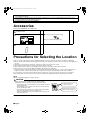
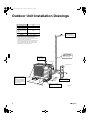
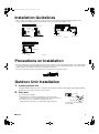
00_CV_3P254362-9K.fm Page 1 Tuesday, October 30, 2012 1:09 PM
INSTALLATION
MANUAL
R410A Split Series
Installation manual
R410A Split series
Models
RXS50K2V1B
RXS60F4V1B
RXG50K3V1B
RX50G3V1B
RX60G3V1B
ARXS50G3V1B
English
Installationsanleitung
Split-Baureihe R410A
Deutsch
Manuel d’installation
Série split R410A
Français
Montagehandleiding
R410A Split-systeem
Manual de instalación
Serie Split R410A
Manuale d’installazione
Serie Multiambienti R410A
Εγχειρßδιο εγκατÜστασηò
διαιροýìενηò σειρÜò R410A
Manual de Instalação
Série split R410A
Рóêоводство по монтажó
Серия R410A с раздельной óстановêой
Montaj kýlavuzlarý
R410A Split serisi
Nederlands
Español
Italiano
ΕλληνικÜ
Portugues
Рóссêий
Türkçe
CE - DECLARACION-DE-CONFORMIDAD
CE - DICHIARAZIONE-DI-CONFORMITA
CE - ∆HΛΩΣΗ ΣΥΜΜΟΡΦΩΣΗΣ
19 ob upoštevanju določb:
20 vastavalt nõuetele:
21 следвайки клаузите на:
22 laikantis nuostatų, pateikiamų:
23 ievērojot prasības, kas noteiktas:
24 održiavajúc ustanovenia:
25 bunun koşullarına uygun olarak:
07 **
08 **
09 **
10 **
11 **
12 **
11 Information * enligt <A> och godkänts av <B> enligt
Certifikatet <C>.
12 Merk *
som det fremkommer i <A> og gjennom positiv
bedømmelse av <B> ifølge Sertifikat <C>.
13 Huom *
jotka on esitetty asiakirjassa <A> ja jotka <B> on
hyväksynyt Sertifikaatin <C> mukaisesti.
14 Poznámka * jak bylo uvedeno v <A> a pozitivně zjištěno <B>
v souladu s osvědčením <C>.
15 Napomena * kako je izloženo u <A> i pozitivno ocijenjeno
od strane <B> prema Certifikatu <C>.
Takayuki Fujii
Managing Director
1st of Nov. 2012
13 **
14 **
15 **
16 **
17 **
18 **
CE - ATITIKTIES-DEKLARACIJA
CE - ATBILSTĪBAS-DEKLARĀCIJA
CE - VYHLÁSENIE-ZHODY
CE - UYUMLULUK-BİLDİRİSİ
DICZ*** on valtuutettu laatimaan Teknisen asiakirjan.
Společnost DICZ*** má oprávnění ke kompilaci souboru technické konstrukce.
DICZ*** je ovlašten za izradu Datoteke o tehničkoj konstrukciji.
A DICZ*** jogosult a műszaki konstrukciós dokumentáció összeállítására.
DICZ*** ma upoważnienie do zbierania i opracowywania dokumentacji konstrukcyjnej.
DICZ*** este autorizat să compileze Dosarul tehnic de construcţie.
19 **
20 **
21 **
22 **
23 **
24 **
25 **
<C>
<B>
74736-KRQ/EMC97-4957
DEKRA (NB0344)
DAIKIN, TCF, 015P9/09-2012
<A>DAIKIN TCF 015P/0-2012
19 Direktive z vsemi spremembami.
20 Direktiivid koos muudatustega.
21 Директиви, с техните изменения.
22 Direktyvose su papildymais.
23 Direktīvās un to papildinājumos.
24 Smernice, v platnom znení.
25 Deǧiştirilmiş halleriyle Yönetmelikler.
DICZ*** je pooblaščen za sestavo datoteke s tehnično mapo.
DICZ*** on volitatud koostama tehnilist dokumentatsiooni.
DICZ*** е оторизирана да състави Акта за техническа конструкция.
DICZ*** yra įgaliota sudaryti šį techninės konstrukcijos failą.
DICZ*** ir autorizēts sastādīt tehnisko dokumentāciju.
Spoločnosť DICZ*** je oprávnená vytvoriť súbor technickej konštrukcie.
DICZ*** Teknik Yapı Dosyasını derlemeye yetkilidir.
21 Забележка * както е изложено в <A> и оценено положително
от <B> съгласно Сертификата <C>.
22 Pastaba *
kaip nustatyta <A> ir kaip teigiamai nuspręsta <B>
pagal Sertifikatą <C>.
23 Piezīmes *
kā norādīts <A> un atbilstoši <B> pozitīvajam
vērtējumam saskaņā ar sertifikātu <C>.
24 Poznámka * ako bolo uvedené v <A> a pozitívne zistené <B>
v súlade s osvedčením <C>.
25 Not *
<A>’da belirtildiği gibi ve <C> Sertifikasına göre
<B> tarafından olumlu olarak değerlendirildiği gibi.
10 Direktiver, med senere ændringer.
11 Direktiv, med företagna ändringar.
12 Direktiver, med foretatte endringer.
13 Direktiivejä, sellaisina kuin ne ovat muutettuina.
14 v platném znění.
15 Smjernice, kako je izmijenjeno.
16 irányelv(ek) és módosításaik rendelkezéseit.
17 z późniejszymi poprawkami.
18 Directivelor, cu amendamentele respective.
16 megfelelnek az alábbi szabvány(ok)nak vagy egyéb irányadó dokumentum(ok)nak, ha azokat előírás szerint használják:
17 spełniają wymogi następujących norm i innych dokumentów normalizacyjnych, pod warunkiem że używane są zgodnie z naszymi
instrukcjami:
18 sunt în conformitate cu următorul (următoarele) standard(e) sau alt(e) document(e) normativ(e), cu condiţia ca acestea să fie utilizate în
conformitate cu instrucţiunile noastre:
19 skladni z naslednjimi standardi in drugimi normativi, pod pogojem, da se uporabljajo v skladu z našimi navodili:
20 on vastavuses järgmis(t)e standardi(te)ga või teiste normatiivsete dokumentidega, kui neid kasutatakse vastavalt meie juhenditele:
21 съответстват на следните стандарти или други нормативни документи, при условие, че се използват съгласно нашите
инструкции:
22 atitinka žemiau nurodytus standartus ir (arba) kitus norminius dokumentus su sąlyga, kad yra naudojami pagal mūsų nurodymus:
23 tad, ja lietoti atbilstoši ražotāja norādījumiem, atbilst sekojošiem standartiem un citiem normatīviem dokumentiem:
24 sú v zhode s nasledovnou(ými) normou(ami) alebo iným(i) normatívnym(i) dokumentom(ami), za predpokladu, že sa používajú v súlade
s našim návodom:
25 ürünün, talimatlarımıza göre kullanılması koşuluyla aşağıdaki standartlar ve norm belirten belgelerle uyumludur:
01 Directives, as amended.
02 Direktiven, gemäß Änderung.
03 Directives, telles que modifiées.
04 Richtlijnen, zoals geamendeerd.
05 Directivas, según lo enmendado.
06 Direttive, come da modifica.
07 Οδηγιών, όπως έχουν τροποποιηθεί.
08 Directivas, conforme alteração em.
09 Директив со всеми поправками.
16 Megjegyzés * a(z) <A> alapján, a(z) <B> igazolta a megfelelést,
a(z) <C> tanúsítvány szerint.
17 Uwaga *
zgodnie z dokumentacją <A>, pozytywną opinią
<B> i Świadectwem <C>.
18 Notă *
aşa cum este stabilit în <A> şi apreciat pozitiv
de <B> în conformitate cu Certificatul <C>.
19 Opomba *
kot je določeno v <A> in odobreno s strani <B>
v skladu s certifikatom <C>.
20 Märkus *
nagu on näidatud dokumendis <A> ja heaks
kiidetud <B> järgi vastavalt sertifikaadile <C>.
Low Voltage 2006/95/EC
Machinery 2006/42/EC **
Electromagnetic Compatibility 2004/108/EC *
Η DICZ*** είναι εξουσιοδοτημένη να συντάξει τον Τεχνικό φάκελο κατασκευής.
A DICZ*** está autorizada a compilar a documentação técnica de fabrico.
Компания DICZ*** уполномочена составить Комплект технической документации.
DICZ*** er autoriseret til at udarbejde de tekniske konstruktionsdata.
DICZ*** är bemyndigade att sammanställa den tekniska konstruktionsfilen.
DICZ*** har tillatelse til å kompilere den Tekniske konstruksjonsfilen.
delineato nel <A> e giudicato positivamente
da <B> secondo il Certificato <C>.
07 Σημείωση * όπως καθορίζεται στο <A> και κρίνεται θετικά από
το <B> σύμφωνα με το Πιστοποιητικό <C>.
08 Nota *
tal como estabelecido em <A> e com o parecer
positivo de <B> de acordo com o Certificado <C>.
09 Примечание * как указано в <A> и в соответствии
с положительным решением <B> согласно
Свидетельству <C>.
10 Bemærk *
som anført i <A> og positivt vurderet af <B>
i henhold til Certifikat <C>.
06 Nota *
DICZ*** is authorised to compile the Technical Construction File.
DICZ*** hat die Berechtigung die Technische Konstruktionsakte zusammenzustellen.
DICZ*** est autorisé à compiler le Dossier de Construction Technique.
DICZ*** is bevoegd om het Technisch Constructiedossier samen te stellen.
DICZ*** está autorizado a compilar el Archivo de Construcción Técnica.
DICZ*** è autorizzata a redigere il File Tecnico di Costruzione.
as set out in <A> and judged positively by <B>
according to the Certificate <C>.
wie in <A> aufgeführt und von <B> positiv beurteilt
gemäß Zertifikat <C>.
tel que défini dans <A> et évalué positivement par
<B> conformément au Certificat <C>.
zoals vermeld in <A> en positief beoordeeld door
<B> overeenkomstig Certificaat <C>.
como se establece en <A> y es valorado
positivamente por <B> de acuerdo con el
Certificado <C>.
10 under iagttagelse af bestemmelserne i:
11 enligt villkoren i:
12 gitt i henhold til bestemmelsene i:
13 noudattaen määräyksiä:
14 za dodržení ustanovení předpisu:
15 prema odredbama:
16 követi a(z):
17 zgodnie z postanowieniami Dyrektyw:
18 în urma prevederilor:
***DICZ = Daikin Industries Czech Republic s.r.o.
01 **
02 **
03 **
04 **
05 **
06 **
05 Nota *
04 Bemerk *
03 Remarque *
02 Hinweis *
01 Note *
01 following the provisions of:
02 gemäß den Vorschriften der:
03 conformément aux stipulations des:
04 overeenkomstig de bepalingen van:
05 siguiendo las disposiciones de:
06 secondo le prescrizioni per:
07 με τήρηση των διατάξεων των:
08 de acordo com o previsto em:
09 в соответствии с положениями:
EN60335-2-40,
CE - IZJAVA O SKLADNOSTI
CE - VASTAVUSDEKLARATSIOON
CE - ДЕКЛАРАЦИЯ-ЗА-ϹЪОТВЕТСТВИЕ
17 m deklaruje na własną i wyłączną odpowiedzialność, że modele klimatyzatorów, których dotyczy niniejsza deklaracja:
18 r declară pe proprie răspundere că aparatele de aer condiţionat la care se referă această declaraţie:
19 o z vso odgovornostjo izjavlja, da so modeli klimatskih naprav, na katere se izjava nanaša:
20 x kinnitab oma täielikul vastutusel, et käesoleva deklaratsiooni alla kuuluvad kliimaseadmete mudelid:
21 b декларира на своя отговорност, че моделите климатична инсталация, за които се отнася тази декларация:
22 t visiška savo atsakomybe skelbia, kad oro kondicionavimo prietaisų modeliai, kuriems yra taikoma ši deklaracija:
23 v ar pilnu atbildību apliecina, ka tālāk uzskaitīto modeļu gaisa kondicionētāji, uz kuriem attiecas šī deklarācija:
24 k vyhlasuje na vlastnú zodpovednosť, že tieto klimatizačné modely, na ktoré sa vzťahuje toto vyhlásenie:
25 w tamamen kendi sorumluluǧunda olmak üzere bu bildirinin ilgili olduǧu klima modellerinin aşaǧıdaki gibi olduǧunu beyan eder:
CE - IZJAVA-O-USKLAĐENOSTI
CE - MEGFELELŐSÉGI-NYILATKOZAT
CE - DEKLARACJA-ZGODNOŚCI
CE - DECLARAŢIE-DE-CONFORMITATE
08 estão em conformidade com a(s) seguinte(s) norma(s) ou outro(s) documento(s) normativo(s), desde que estes sejam utilizados de
acordo com as nossas instruções:
09 соответствуют следующим стандартам или другим нормативным документам, при условии их использования согласно нашим
инструкциям:
10 overholder følgende standard(er) eller andet/andre retningsgivende dokument(er), forudsat at disse anvendes i henhold til vore
instrukser:
11 respektive utrustning är utförd i överensstämmelse med och följer följande standard(er) eller andra normgivande dokument, under
förutsättning att användning sker i överensstämmelse med våra instruktioner:
12 respektive utstyr er i overensstemmelse med følgende standard(er) eller andre normgivende dokument(er), under forutssetning av at
disse brukes i henhold til våre instrukser:
13 vastaavat seuraavien standardien ja muiden ohjeellisten dokumenttien vaatimuksia edellyttäen, että niitä käytetään ohjeidemme
mukaisesti:
14 za předpokladu, že jsou využívány v souladu s našimi pokyny, odpovídají následujícím normám nebo normativním dokumentům:
15 u skladu sa slijedećim standardom(ima) ili drugim normativnim dokumentom(ima), uz uvjet da se oni koriste u skladu s našim uputama:
RXG50K3V1B, RXS50K2V1B, RXS60F4V1B, RX50G3V1B, RX60G3V1B, ARXS50G3V1B
01 are in conformity with the following standard(s) or other normative document(s), provided that these are used in accordance with our
instructions:
02 der/den folgenden Norm(en) oder einem anderen Normdokument oder -dokumenten entspricht/entsprechen, unter der Voraussetzung,
daß sie gemäß unseren Anweisungen eingesetzt werden:
03 sont conformes à la/aux norme(s) ou autre(s) document(s) normatif(s), pour autant qu'ils soient utilisés conformément à nos instructions:
04 conform de volgende norm(en) of één of meer andere bindende documenten zijn, op voorwaarde dat ze worden gebruikt overeenkomstig
onze instructies:
05 están en conformidad con la(s) siguiente(s) norma(s) u otro(s) documento(s) normativo(s), siempre que sean utilizados de acuerdo con
nuestras instrucciones:
06 sono conformi al(i) seguente(i) standard(s) o altro(i) documento(i) a carattere normativo, a patto che vengano usati in conformità alle
nostre istruzioni:
07 είναι σύμφωνα με το(α) ακόλουθο(α) πρότυπο(α) ή άλλο έγγραφο(α) κανονισμών, υπό την προϋπόθεση ότι χρησιμοποιούνται σύμφωνα
με τις οδηγίες μας:
CE - ERKLÆRING OM-SAMSVAR
CE - ILMOITUS-YHDENMUKAISUUDESTA
CE - PROHLÁŠENÍ-O-SHODĚ
09 u заявляет, исключительно под свою ответственность, что модели кондиционеров воздуха, к которым относится настоящее заявление:
10 q erklærer under eneansvar, at klimaanlægmodellerne, som denne deklaration vedrører:
11 s deklarerar i egenskap av huvudansvarig, att luftkonditioneringsmodellerna som berörs av denna deklaration innebär att:
12 n erklærer et fullstendig ansvar for at de luftkondisjoneringsmodeller som berøres av denne deklarasjon, innebærer at:
13 j ilmoittaa yksinomaan omalla vastuullaan, että tämän ilmoituksen tarkoittamat ilmastointilaitteiden mallit:
14 c prohlašuje ve své plné odpovědnosti, že modely klimatizace, k nimž se toto prohlášení vztahuje:
15 y izjavljuje pod isključivo vlastitom odgovornošću da su modeli klima uređaja na koje se ova izjava odnosi:
16 h teljes felelőssége tudatában kijelenti, hogy a klímaberendezés modellek, melyekre e nyilatkozat vonatkozik:
CE - DECLARAÇÃO-DE-CONFORMIDADE
CE - ЗАЯВЛЕНИЕ-О-СООТВЕТСТВИИ
CE - OVERENSSTEMMELSESERKLÆRING
CE - FÖRSÄKRAN-OM-ÖVERENSTÄMMELSE
01 a declares under its sole responsibility that the air conditioning models to which this declaration relates:
02 d erklärt auf seine alleinige Verantwortung daß die Modelle der Klimageräte für die diese Erklärung bestimmt ist:
03 f déclare sous sa seule responsabilité que les appareils d'air conditionné visés par la présente déclaration:
04 l verklaart hierbij op eigen exclusieve verantwoordelijkheid dat de airconditioning units waarop deze verklaring betrekking heeft:
05 e declara baja su única responsabilidad que los modelos de aire acondicionado a los cuales hace referencia la declaración:
06 i dichiara sotto sua responsabilità che i condizionatori modello a cui è riferita questa dichiarazione:
07 g δηλώνει με αποκλειστική της ευθύνη ότι τα μοντέλα των κλιματιστικών συσκευών στα οποία αναφέρεται η παρούσα δήλωση:
08 p declara sob sua exclusiva responsabilidade que os modelos de ar condicionado a que esta declaração se refere:
Daikin Industries Czech Republic s.r.o.
CE - DECLARATION-OF-CONFORMITY
CE - KONFORMITÄTSERKLÄRUNG
CE - DECLARATION-DE-CONFORMITE
CE - CONFORMITEITSVERKLARING
3P291651-7D_offset.book Page 1 Sunday, July 8, 2012 3:14 PM
3P327445-8B
01_EN_3P254362-9K.fm Page 1 Tuesday, October 30, 2012 7:31 PM
Safety Precautions
• The precautions described herein are classified as WARNING and CAUTION. They both contain important
information regarding safety. Be sure to observe all precautions without fail.
• Meaning of WARNING and CAUTION notices
WARNING .... Failure to follow these instructions properly may result in personal injury or loss of life.
CAUTION ..... Failure to observe these instructions properly may result in property damage or personal injury, which
may be serious depending on the circumstances.
• The safety marks shown in this manual have the following meanings:
Be sure to follow the instructions.
Be sure to establish an earth connection.
Never attempt.
• After completing installation, conduct a trial operation to check for faults and explain to the customer how to operate
the air conditioner and take care of it with the aid of the operation manual.
• The English text is the original instruction. Other languages are translations of the original instructions.
WARNING
• Ask your dealer or qualified personnel to carry out installation work.
Do not attempt to install the air conditioner yourself. Improper installation may result in water leakage, electric shocks or fire.
• Install the air conditioner in accordance with the instructions in this installation manual.
Improper installation may result in water leakage, electric shocks or fire.
• Be sure to use only the specified accessories and parts for installation work.
Failure to use the specified parts may result in the unit falling, water leakage, electric shocks or fire.
• Install the air conditioner on a foundation strong enough to withstand the weight of the unit.
A foundation of insufficient strength may result in the equipment falling and causing injury.
• Electrical work must be performed in accordance with relevant local and national regulations and with instructions
in this installation manual. Be sure to use a dedicated power supply circuit only.
Insufficiency of power circuit capacity and improper workmanship may result in electric shocks or fire.
• Use a cable of suitable length.
Do not use tapped wires or an extension lead, as this may cause overheating, electric shocks or fire.
• Make sure that all wiring is secured, the specified wires are used, and that there is no strain on the terminal connections or wires.
Improper connections or securing of wires may result in abnormal heat build-up or fire.
• When wiring the power supply and connecting the wiring between the indoor and outdoor units, position the wires
so that the control box lid can be securely fastened.
Improper positioning of the control box lid may result in electric shocks, fire or over heating terminals.
• If refrigerant gas leaks during installation, ventilate the area immediately.
Toxic gas may be produced if the refrigerant comes into contact with fire.
• After completing installation, check for refrigerant gas leakage.
Toxic gas may be produced if the refrigerant gas leaks into the room and comes into contact with a source of fire, such as a fan heater, stove or cooker.
• When installing or relocating the air conditioner, be sure to bleed the refrigerant circuit to ensure it is free of air, and
use only the specified refrigerant (R410A).
The presence of air or other foreign matter in the refrigerant circuit causes abnormal pressure rise, which may result in equipment damage and even injury.
• During installation, attach the refrigerant piping securely before running the compressor.
If the refrigerant pipes are not attached and the stop valve is open when the compressor is run, air will be sucked in, causing abnormal
pressure in the refrigeration cycle, which may result in equipment damage and even injury.
• During pump-down, stop the compressor before removing the refrigerant piping.
If the compressor is still running and the stop valve is open during pump-down, air will be sucked in when the refrigerant piping is removed,
causing abnormal pressure in the refrigeration cycle, which may result in equipment damage and even injury.
• Be sure to earth the air conditioner.
Do not earth the unit to a utility pipe, lightning conductor or telephone earth lead. Imperfect earthing may result in electric shocks.
• Be sure to install an earth leakage breaker.
Failure to install an earth leakage breaker may result in electric shocks or fire.
CAUTION
• Do not install the air conditioner at any place where there is a danger of flammable gas leakage.
In the event of a gas leakage, build-up of gas near the air conditioner may cause a fire to break out.
• While following the instructions in this installation manual, install drain piping to ensure proper drainage and
insulate piping to prevent condensation.
Improper drain piping may result in indoor water leakage and property damage.
• Tighten the flare nut according to the specified method such as with a torque wrench.
If the flare nut is too tight, it may crack after prolonged use, causing refrigerant leakage.
• Make sure to provide for adequate measures in order to prevent that the outdoor unit be used as a shelter by small animals.
Small animals making contact with electrical parts can cause malfunctions, smoke or fire. Please instruct the customer to keep the area around the unit clean.
1
■English
01_EN_3P254362-9K.fm Page 2 Tuesday, October 30, 2012 7:31 PM
• The temperature of refrigerant circuit will be high, please keep the inter-unit wire away from copper pipes that are
not thermally insulated.
• This appliance is intended to be used by expert or trained users in shops, in light industry and on farms, or for
commercial and household use by lay persons.
• Sound pressure level is less than 70 dB (A).
Accessories
Accessories supplied with the outdoor unit:
A Installation manual
1
B Drain plug (only heat pump models)
C Refrigerant charge label
1
1
There is on the bottom packing case.
D Multilingual fluorinated greenhouse gases label
1
Precautions for Selecting the Location
1) Choose a place solid enough to bear the weight and vibration of the unit, where the operation noise will not be amplified.
2) Choose a location where the hot air discharged from the unit or the operation noise will not cause a nuisance to the neighbours of
the user.
3) Avoid places near a bedroom and the like, so that the operation noise will cause no trouble.
4) There must be sufficient spaces for carrying the unit into and out of the site.
5) There must be sufficient space for air passage and no obstructions around the air inlet and the air outlet.
6) The site must be free from the possibility of flammable gas leakage in a nearby place.
7) Install units, power cords and inter-unit wire at least 3m away from television and radio sets. This is to prevent interference to
images and sounds. (Noises may be heard even if they are more than 3m away depending on radio wave conditions.)
8) In coastal areas or other places with salty atmosphere of sulfate gas, corrosion may shorten the life of the air conditioner.
9) Since drain flows out of the outdoor unit, do not place under the unit anything which must be kept away from moisture.
NOTE
Cannot be installed hanging from ceiling or stacked.
CAUTION
When operating the air conditioner in a low outdoor ambient
temperature, be sure to follow the instructions described below.
• To prevent exposure to wind, install the outdoor unit with its suction
side facing the wall.
• Never install the outdoor unit at a site where the suction side may
be exposed directly to wind.
• To prevent exposure to wind, it is recommended to install a baffle
plate on the air discharge side of the outdoor unit.
• In heavy snowfall areas, select an installation site where the snow
will not affect the unit.
■English
Construct a large canopy.
Construct a pedestal.
Install the unit high enough off the
ground to prevent burying in snow.
2
01_EN_3P254362-9K.fm Page 3 Tuesday, October 30, 2012 7:31 PM
Outdoor Unit Installation Drawings
Max. allowable piping length
30m
** Min. allowable piping length
1.5m
Max. allowable piping height
20m
Additional refrigerant
required for refrigerant
pipe exceeding 10m in
length.
20g/m
Gas pipe
O.D. 12.7mm
Liquid pipe
O.D. 6.4mm
*
Wrap the insulation
pipe with the finishing
tape from bottom to top.
* Be sure to add the proper amount of additional refrigerant.
Failure to do so may result in reduced performance.
** The suggested shortest pipe length is 1.5m, in order to avoid
noise from the outdoor unit and vibration.
(Mechanical noise and vibration may occur depending on how
the unit is installed and the environment in which it is used.)
When connecting the FVXS indoor unit, the shortest piping
length should be no less than around 2.5m.
CAUTION
**Set the piping length
from 1.5m to 30m.
Allow 300mm of
work space below
the ceiling surface.
Service lid
Stop valve cover
250m
m from
In sites with poor drainage,
use block bases for outdoor
unit.
Adjust foot height until the
unit is leveled. Otherwise,
water leakage or pooling of
water may occur.
3
0
(Foot
580
ole ce
bolt-h
le
o
t-h
ol
b
t s)
oo re
(F ent
c
33
ntres)
120
(From
unit’s
side)
wall
Allow space for piping
and electrical servicing.
Where there is a danger of
the unit falling, use foot bolts,
or wires.
unit: mm
■English
01_EN_3P254362-9K.fm Page 4 Tuesday, October 30, 2012 7:31 PM
Installation Guidelines
• Where a wall or other obstacle is in the path of outdoor unit’s inlet or outlet airflow, follow the installation guidelines below.
• For any of the below installation patterns, the wall height on the outlet side should be 1200mm or less.
Wall facing one side
More than 100
Walls facing two sides
More than 350
Direction
of air
1200
or less
More
than 100
More
than 350
More than 50
Side view
More than 50
Top view
Walls facing three sides
More than 100
More than 350
More than 50
Top view
unit: mm
Precautions on Installation
20
• Check the strength and level of the installation ground so that the unit will not cause any operating vibration or noise after installed.
• In accordance with the foundation drawing, fix the unit securely by means of the foundation bolts. (Prepare 4 sets of M8 or M10
foundation bolts, nuts and washers each which are available on the market.)
• It is best to screw in the foundation bolts until their ends are 20mm from the foundation surface.
Outdoor Unit Installation
1.
Installing outdoor unit
1) When installing the outdoor unit, refer to “Precautions for Selecting the Location” and the “Outdoor Unit Installation Drawings”.
2) If drain work is necessary, follow the procedures below.
2.
Drain work
1) Use drain plug for drainage.
2) If the drain port is covered by a mounting base or floor surface, place
additional foot bases of at least 30mm in height under the outdoor unit’s feet.
3) In cold areas, do not use a drain hose with the outdoor unit.
(Otherwise, drain water may freeze, impairing heating performance.)
Drain port
Bottom frame
Drain plug
Hose (available commercially,
inner dia. 16mm)
■English
4
01_EN_3P254362-9K.fm Page 5 Tuesday, October 30, 2012 7:31 PM
Outdoor Unit Installation
3.
Flaring the pipe end
1) Cut the pipe end with a pipe cutter.
2) Remove burrs with the cut surface facing
downward so that the chips do not enter the pipe.
3) Put the flare nut on the pipe.
4) Flare the pipe.
5) Check that the flaring is properly made.
(Cut exactly at
right angles.)
Remove burrs.
Flaring
Set exactly at the position shown below.
A
Flare tool for R410A
Conventional flare tool
Clutch-type
Clutch-type (Rigid-type) Wing-nut type (Imperial-type)
A
Die
0-0.5mm
1.0-1.5mm
1.5-2.0mm
Check
Flare’s inner surface
must be flaw-free.
The pipe end must
be evenly flared in a
perfect circle.
Make sure that the
flare nut is fitted.
WARNING
• Do not use mineral oil on flared part.
• Prevent mineral oil from getting into the system as this would reduce the lifetime of the units.
• Never use piping which has been used for previous installations. Only use parts which are delivered with the unit.
• Do never install a drier to this R410A unit in order to guarantee its lifetime.
• The drying material may dissolve and damage the system.
• Incomplete flaring may cause refrigerant gas leakage.
4.
Refrigerant piping
CAUTION
• Use the flare nut fixed to the main unit. (To prevent cracking of the flare nut by aged deterioration.)
• To prevent gas leakage, apply refrigeration oil only to the inner surface of the flare. (Use refrigeration oil for R410A.)
• Use torque wrenches when tightening the flare nuts to prevent damage to the flare nuts and gas leakage.
Align the centres of both flares and tighten the flare nuts 3 or 4 turns by hand. Then tighten them fully with the torque wrenches.
[Apply oil]
[Tighten]
Apply refrigeration oil to
the inner surface of the
flare.
Do not apply refrigeration
oil to the outer surface.
Torque wrench
Flare nut
Spanner
Piping union
Flare nut
Do not apply refrigeration oil to
the flare nut to avoid tightening
with excessive torque.
Valve cap tightening torque
Flare nut tightening torque
Gas side
Liquid side
Gas side
Liquid side
1/2 inch
1/4 inch
1/2 inch
1/4 inch
49.5-60.3N • m
14.2-17.2N • m
48.1-59.7N • m
21.6-27.4N • m
(505-615kgf • cm)
(144-175kgf • cm)
(490-610kgf • cm)
(220-280kgf • cm)
Service port cap tightening torque
10.8-14.7N • m (110-150kgf • cm)
5
■English
01_EN_3P254362-9K.fm Page 6 Tuesday, October 30, 2012 7:31 PM
5.
Purging air and checking gas leakage
• When piping work is completed, it is necessary to purge the air and check for gas leakage.
WARNING
• Do not mix any substance other than the specified refrigerant (R410A) into the refrigeration cycle.
• When refrigerant gas leaks occur, ventilate the room as soon and as much as possible.
• R410A, as well as other refrigerants, should always be recovered and never be released directly into the environment.
• Use a vacuum pump for R410A exclusively. Using the same vacuum pump for different refrigerants may damage the vacuum
pump or the unit.
• If using additional refrigerant, perform air purging from the refrigerant pipes and
indoor unit using a vacuum pump, then charge additional refrigerant.
• Use a hexagonal wrench (4mm) to operate the stop valve rod.
• All refrigerant pipe joints should be tightened with a torque wrench at the specified
tightening torque.
Compound
Pressure metre
pressure gauge
Gauge
manifold
High-pressure
valve Valve caps
Low-pressure
valve
Charging
hoses
Liquid
stop
valve
Gas
stop
Vacuum pump Service port valve
1) Connect projection side of charging hose (which comes from gauge manifold) to gas stop valve’s service port.
2) Fully open gauge manifold’s low-pressure valve (Lo) and completely close its high-pressure valve (Hi).
(High-pressure valve subsequently requires no operation.)
3) Do vacuum pumping and make sure that the compound pressure gauge reads –0.1MPa (–76cmHg).*1
4) Close gauge manifold’s low-pressure valve (Lo) and stop vacuum pump.
(Keep this state for a few minutes to make sure that the compound pressure gauge pointer does not swing back.)*2
5) Remove caps from liquid stop valve and gas stop valve.
6) Turn the liquid stop valve’s rod 90 degrees counterclockwise with a hexagonal wrench to open valve.
Close it after 5 seconds, and check for gas leakage.
Using soapy water, check for gas leakage from indoor unit’s flare and outdoor unit’s flare and valve rods.
After the check is complete, wipe all soapy water off.
7) Disconnect charging hose from gas stop valve’s service port, then fully open liquid and gas stop valves.
(Do not attempt to turn valve rod beyond its stop.)
8) Tighten valve caps and service port caps for the liquid and gas stop valves with a torque wrench at the specified torques.
*1.Pipe length vs. vacuum pump run time
Pipe length
Up to 15m
More than 15m
Run time
Not less than 10 min.
Not less than 15 min.
*2.If the compound pressure gauge pointer swings back, refrigerant may have water content or a loose pipe joint may exists.
Check all pipe joints and retighten nuts as needed, then repeat steps 2) through 4).
■English
6
01_EN_3P254362-9K.fm Page 7 Tuesday, October 30, 2012 7:31 PM
Outdoor Unit Installation
6.
Refilling the refrigerant
Check the type of refrigerant to be used on the machine nameplate.
Precautions when adding R410A
Fill from the gas pipe in liquid form.
It is a mixed refrigerant, so adding it in gas form may cause the refrigerant composition to change, preventing normal operation.
1) Before filling, check whether the cylinder has a siphon attached or not. (It should have something like “liquid filling siphon
attached” displayed on it.)
Filling a cylinder with an attached siphon
Filling other cylinders
Turn the cylinder upside-down
when filling.
Stand the cylinder upright when
filling.
There is a siphon pipe inside, so the
cylinder need not be upside-down to
fill with liquid.
• Be sure to use the R410A tools to ensure pressure and to prevent foreign objects entering.
Important information regarding the refrigerant used
This product contains fluorinated greenhouse gases covered by
the Kyoto Protocol. Do not vent gases into the atmosphere.
Refrigerant type: R410A
GWP(1) value: 1975
= global warming potential
4
Please fill in with indelible ink,
n 1 the factory refrigerant charge of the product,
n 2 the additional refrigerant amount charged in the field and
n 1 + 2 the total refrigerant charge
on the refrigerant charge label supplied with the product.
1
(1) GWP
1 factory refrigerant charge of the
product:
see unit name plate
The filled out label must be adhered in the
proximity of the product charging port (e.g.
onto the inside of the stop valve cover).
2 additional refrigerant amount
charged in the field
3 total refrigerant charge
4 Contains fluorinated greenhouse
gases covered by the Kyoto
Protocol
2
5 outdoor unit
3
6
6 refrigerant cylinder and manifold
for charging
5
NOTE
National implementation of EU regulation on certain fluorinated greenhouse gases may require to provide the appropriate official
national language on the unit. Therefore an additional multilingual fluorinated greenhouse gases label is supplied with the unit.
Sticking instructions are illustrated on the backside of that label.
7.
Refrigerant piping work
7-1 Caution on pipe handling
1) Protect the open end of the pipe against dust and moisture.
2) All pipe bends should be as gentle as possible. Use a pipe bender for
bending.
Rain
7-2 Selection of copper and heat insulation materials
When using commercial copper pipes and fittings, observe the following:
1) Insulation material: Polyethylene foam
Heat transfer rate: 0.041 to 0.052W/mK (0.035 to 0.045kcal/mh°C)
Refrigerant gas pipe’s surface temperature reaches 110°C max.
Choose heat insulation materials that will withstand this temperature.
2) Be sure to insulate both the gas and liquid piping and to provide insulation
dimensions as below.
If no flare cap is
available, cover the
flare mouth with
tape to keep dirt or
water out.
Inter-unit wire
Gas pipe
Gas side
Liquid side
O.D. 12.7mm
O.D. 6.4mm
Minimum bend radius
40mm or more
30mm or more
Thickness 0.8mm (C1220T-O)
Gas pipe thermal Liquid pipe thermal
insulation
insulation
I.D. 14-16mm
I.D. 8-10mm
Thickness 10mm Min.
• Use separate thermal insulation pipes for gas and liquid refrigerant pipes.
7
Wall
Be sure to
place a cap.
Gas pipe
insulation
Liquid pipe
Liquid pipe
insulation
Finishing tape
Drain hose
■English
01_EN_3P254362-9K.fm Page 8 Tuesday, October 30, 2012 7:31 PM
Pump Down Operation
In order to protect the environment, be sure to pump down when relocating or disposing of the unit.
1)
2)
3)
4)
Remove the valve cap from liquid stop valve and gas stop valve.
Carry out forced cooling operation.
After 5 to 10 minutes, close the liquid stop valve with a hexagonal wrench.
After 2 to 3 minutes, close the gas stop valve and stop forced cooling operation.
Hexagonal
wrench
Close
Forced cooling operation
■ Using the indoor unit ON/OFF switch
Press the indoor unit ON/OFF switch for at least 5 seconds. (The operation will start.) Liquid stop valve
• Forced cooling operation will stop automatically after around 15 minutes.
Gas stop valve
To stop the operation, press the indoor unit ON/OFF switch.
Service port
■ Using the indoor unit’s remote controller
1) Press “MODE” button and select the cooling mode.
2) Press “ON/OFF” button to turn on the system.
3) Press both of “TEMP” button and “MODE” button at the same time.
4) Press “MODE” button twice. ( will be displayed and the unit will enter forced cooling operation.)
• Forced cooling operation will stop automatically after around 30 minutes.
To stop the operation, press “ON/OFF” button.
■ Using the outdoor unit forced cooling
operation switch
Forced cooling operation can be performed
when the outdoor unit forced cooling
operation switch is pressed within around
3 minutes after power is supplied.
• Push on “ ” (SW1) with a screwdriver.
(The operation will start.)
• Forced cooling operation will stop
automatically after around 15 minutes.
To stop the operation, press the switch
Screwdriver
(SW1).
1
2
Valve cap
Forced cooling
operation switch
(SW1)
3
Push
Standby Electricity Saving
The standby electricity saving function turns off power supply to the outdoor unit and sets the indoor unit into
standby electricity saving mode, thus reducing the power consumption of the air conditioner.
The standby electricity saving function works on the following indoor unit.
FTXS50K2V1B
CAUTION
• The standby electricity saving function cannot be used for models other than the specified one.
■ Procedure for turning on standby electricity saving function
1) Check that the main power supply is turned off. Turn it off if has not
been turned off.
2) Remove the stop valve cover.
3) Disconnect the selective connector for standby electricity saving.
4) Turn on the main power supply.
1
2
3
Standby electricity saving
function off.
1
2
3
Standby electricity saving
function on.
The standby electricity saving function is turned off before shipping.
CAUTION
• Before connecting or disconnecting the selective connector for standby electricity saving, make sure that the main power
supply is turned off.
• The selective connector for standby electricity saving is required if an indoor unit other than the above applicable one is
connected.
■English
8
01_EN_3P254362-9K.fm Page 9 Tuesday, October 30, 2012 7:31 PM
Facility Setting
(cooling at low outdoor temperature)
This function is designed for facilities such as equipment or computer rooms. It is never to be used in a
residence or office where people occupy the space.
■ Cutting jumper 6 (J6) on the circuit board will expand the operation range down to –10°C. However it will stop if the outdoor
temperature drops below –18°C and start back up once the temperature rises again.
1) Remove the 3 screws on the side and remove the top plate of the outdoor unit.
2) Remove the drip proof cover.
3) Cut the jumper (J6) of the PCB inside.
Top plate
1) Remove the
3 screws.
Drip proof cover
2) Remove the drip
proof cover.
PCB
J7
J8
J6
J5
GND
3) Cut jumper J6.
CAUTION
• If the outdoor unit is installed where the heat exchanger of the unit is exposed to direct wind, provide a windbreak wall.
• Intermittent noises may be produced by the indoor unit due to the outdoor fan turning on and off when using facility settings.
• Do not place humidifiers or other items which might raise the humidity in rooms where facility settings are being used.
A humidifier might cause dew condensation from the indoor unit outlet vent.
• Cutting jumper 6 (J6) sets the indoor fan tap to the highest position. Notify the user about this.
Wiring
WARNING
• Do not use tapped wires, stranded wires, extension cords, or starburst connections, as they may cause overheating, electrical
shock, or fire.
• Do not use locally purchased electrical parts inside the product. (Do not branch the power for the drain pump, etc., from the
terminal block.) Doing so may cause electric shock or fire.
• Be sure to install an earth leak detector. (One that can handle higher harmonics.)
(This unit uses an inverter, which means that it must be used an earth leak detector capable handling harmonics in order to
prevent malfunctioning of the earth leak detector itself.)
• Use an all-pole disconnection type breaker with at least 3mm between the contact point gaps.
• Do not connect the power wire to the indoor unit. Doing so may cause electric shock or fire.
• Do not turn on the safety breaker until all work is completed.
1) Strip the insulation from the wire (20mm).
2) Connect the inter-unit wire between the indoor
and outdoor units so that the terminal
numbers match. Tighten the terminal screws
securely. We recommend a flathead
screwdriver be used to tighten the screws.
Firmly fix the wires with
the terminal screws.
Outdoor unit
Inter-unit wire
4-core 1.5mm² or more
H05RN
Indoor
unit
1 23
1
2
3
Power supply wire
3-core 2.5mm² or more
H05RN
Safety
breaker
20A
Firmly fix the wires with
the terminal screws.
9
LN
Earth leakage
circuit breaker
Power
supply
50Hz 220-240V
Earth
■English
01_EN_3P254362-9K.fm Page 10 Tuesday, October 30, 2012 7:31 PM
1
2
Power supply
terminal block
3
1
2
Service lid
3
Shape wires so
that the service lid
and stop valve
cover fit securely.
Screw
Observe the notes mentioned below when wiring to the power supply terminal block.
Precautions to be taken for power supply wiring.
CAUTION
• When connecting the wires to the terminal block using a single core
wire, be sure to perform curling.
Problems with the work may cause heat and fires.
Excessive strip length
may cause electrical
shock or leakage.
Strip wire end
to this point.
Good
Wrong
Good
Wrong
Stripping wire at terminal block
• If the stranded wires must be used, make sure to use the round
crimp-style terminal for connection to the power supply terminal
block. Place the round crimp-style terminals on the wires up to the
covered part and secure in place.
Round crimp-style
terminal
Stranded wire
3) Pull the wire and make sure that it does not disconnect. Then fix the wire in place with a wire stop.
Wiring diagram
:
Terminal strip
:
Connector
:
Relay connector
:
Connection
:
Terminal
BLK
:
Black
ORG
:
Orange
BLU
:
Blue
RED
:
Red
BRN
:
Brown
WHT
:
White
GRN
:
Green
YLW
:
Yellow
■English
Field wiring
10
01_EN_3P254362-9K.fm Page 11 Tuesday, October 30, 2012 7:31 PM
Wiring
Notes
:
:
:
:
:
:
:
Refer to the nameplate of the unit for power requirements.
TO INDOOR UNIT
POWER SUPPLY
IN CASE OF COOLING ONLY TYPE
OUTDOOR
CONDENSER
DISCHARGE
To indoor unit
Power supply
In case of cooling only type
Outdoor
Condenser
Discharge
Wiring diagram parts table
C7,C8..................... Capacitor
DB1,DB3................ Diode bridge
FU1,FU2,FU3 ........ Fuse
FU4........................ Field fuse
IPM........................ Intelligent power module
L............................. Live
L803,L804.............. Reactor
M1C .......................Compressor motor
M1F........................ Fan motor
MRCW,MRM10,
MRM20,MR30........ Magnetic relay
N.............................Neutral
Q1L........................ Overload protector
Q1DI....................... Earth leak detector
PCB1,PCB2 ...........Printed circuit board
S10,S11,S12,S20,
S40,S70,S80,S90
HL3,HN3,X11A.......Connector
R1T,R2T,R3T ......... Thermistor
SA1 ........................Surge absorber
V1,V2,V3................ Varistor
X1M........................ Terminal strip
Y1E ........................Electronic expansion valve coil
Y1S ........................Reversing solenoid valve
Z1C~Z4C................Noise filter (ferrite core)
........................ Protective earth
........................ Earth
Trial Operation and Testing
1.
Trial operation and testing
1-1 Measure the supply voltage and make sure that it falls in the specified range.
1-2 Trial operation should be carried out in either cooling or heating mode.
■ For heat pump
• In cooling mode, select the lowest programmable temperature; in heating mode, select the highest programmable temperature.
1) Trial operation may be disabled in either mode depending on the room temperature.
2) After trial operation is complete, set the temperature to a normal level (26°C to 28°C in cooling mode, 20°C to 24°C in
heating mode).
3) For protection, the system disables restart operation for 3 minutes after it is turned off.
■ For cooling only
• Select the lowest programmable temperature.
1) Trial operation in cooling mode may be disabled depending on the room temperature.
2) After trial operation is complete, set the temperature to a normal level (26°C to 28°C).
3) For protection, the system disables restart operation for 3 minutes after it is turned off.
1-3 Carry out the test operation in accordance with the operation manual to ensure that all functions and parts,
such as louver movement, are working properly.
• The air conditioner requires a small amount of power in its standby mode. If the system is not to be used for some
time after installation, shut off the circuit breaker to eliminate unnecessary power consumption.
• If the circuit breaker trips to shut off the power to the air conditioner, the system will restore the original operation
mode when the circuit breaker is opened again.
2.
Test items
Test items
Symptom
Indoor and outdoor units are installed properly on solid bases.
Fall, vibration, noise
No refrigerant gas leaks.
Incomplete cooling/heating
function
Refrigerant gas and liquid pipes and indoor drain hose extension are
thermally insulated.
Water leakage
Draining line is properly installed.
Water leakage
System is properly earthed.
Electrical leakage
The specified wires are used for inter-unit wiring.
Inoperative or burn damage
Indoor or outdoor unit’s air inlet or air outlet has clear path of air.
Stop valves are opened.
Incomplete cooling/heating
function
Indoor unit properly receives remote control commands.
Inoperative
11
Check
■English
00_CV_3P254362-9K.fm Page 2 Tuesday, October 30, 2012 1:09 PM
Two-dimensional bar code is a code
for manufacturing.
3P254362-9K M12B166
(1210) HT