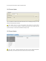
1
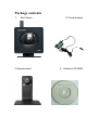
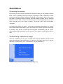
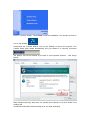
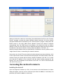
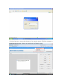
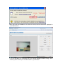
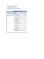
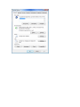
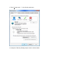
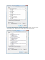
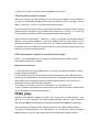
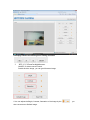
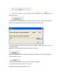
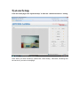
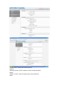
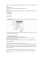
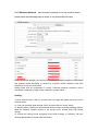
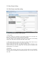
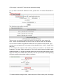
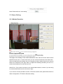
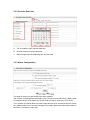
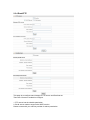
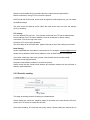
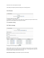
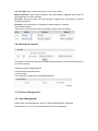
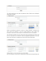
User's Manual
V1.3
Product name: Mini series network camera
CONTENT
PRODUCT INSTRUCTION .................................................................................................................3
NOTICE ..................................................................................................................................................3
PACKAGE CONTENTS .......................................................................................................................4
INSTALLATION ....................................................................................................................................5
CONNECTING THE CAMERA ...................................................................................................................5
CAMERA SETUP INSTALLATION & USAGE..............................................................................................5
ACCESSING THE NETWORK CAMERA ........................................................................................7
INSTALLING THE ACTIVEX ....................................................................................................................7
CHECKING THE NETWORK SETTINGS ...................................................................................................14
WITH A PASSWORD TO PREVENT UNAUTHORIZED ACCESS....................................................................14
MAIN PAGE .........................................................................................................................................14
SYSTEM SETUP..................................................................................................................................17
2.1 NETWORK .....................................................................................................................................19
2.1.1 TCP/IP ............................................................................................................ 19
2.1.2 Wireless Network ............................................................................................ 21
2.1.3 UPNP .............................................................................................................. 22
2.1.4 PPOE Account Configure................................................................................ 22
2.1.5 DDNS.............................................................................................................. 23
2.2 VIDEO STREAM SETTING. ..............................................................................................................24
2.2.1 Click ‘Stream’ enter Video setting.................................................................... 24
2.2.2 Night Vision Setting......................................................................................... 26
2.2.3 OSD Setting............................................................................................... 26
2.3 ALARM SETTING............................................................................................................................27
2.3.1 Motion Detection ............................................................................................. 27
2.3.2 Periodic Detection........................................................................................... 28
2.3.3 Alarm Configuration ........................................................................................ 28
2.3.5 Periodic sending ............................................................................................. 30
2.3.6 I/O alarm ......................................................................................................... 31
2.4 RECORDER SETTING .......................................................................................................................31
2.4.1 Device storage ................................................................................................ 31
2.4.2 Storage documents ......................................................................................... 32
2.5 SYSTEM MANAGEMENT ................................................................................................................32
2.5.1 User Management .......................................................................................... 32
2.5.2 Firmware Update ............................................................................................ 34
2.5.3 Factory Defaults .............................................................................................. 34
2.5.4 Device Status .................................................................................................. 35
2.5.5 Reboot ............................................................................................................ 35
Product instruction
The use of surveillance devices may be prohibited by law in your country. It is the user’s
responsibility to ensure that the operation of such devices is legal before installing this unit
for its intended use
It is important to first verify that all contents received are complete according to the
Package contents listed below. Take notice of the section Quick Installation Guide before
the Network Camera is installed; then carefully read and follow the instructions in the
Installation chapter to avoid damages due to faulty assembly and installation
The Network Camera is a network device and its use should be straightforward for those
who have basic network knowledge. It is designed for various applications, such as
security surveillance etc.
Notice
1. TF Card
The TF card format should be FAT32, if not, please format it .
2. Power turn on, Power off
The interval time of power on/off must be more than 10seconds, otherwise, it will cause
flash or CPU with serious damaged.
3. If Shaking the Mini cameras, the click voice from camera is normal. Please don’t shake
the Mini camera deliberately to avoid damaging component.
4. When the Mini series Ip camera are in strong light, the slight color cast of image is
normal.
5. As the MINI series with COMS sensor, so the colors are more relatively bright in default
setting. You can adjust it according to the condition.
6. Please check the adaptor, we provide the standard adaptor; please do not change
other adaptors to use.
7. When you update cameras, please note:
Please connect the camera with computer via network cable directly
Please close the other program and windows in the computer;
Please keeps the good power connecting when you update the firmware.
Package contents
1、
Mini Series
3.Camera stand
2、Power adaptor
4、Software CD-ROM
Installation
Connecting the camera
Please verify the all contents received are complete according to the package contents
listed .First of all, making sure that the integrity of package in order to determine whether
the product had been shocked violently or impacted during transport, then we can check
the cause of hardware failure accordingly and find suitable solutions. Using a standard
Ethernet network cable, connect the camera to your network (depending on your own
setup, this may be to your router or switch). The length of the cable should below
100meters.
Connecting the adaptor with power , camera device will detect automatically, the “power”
status LED will blinks alternately in green and orange, then infrared light will be fully bright
by self-test. After self-test, infrared light will extinguish automatically, and the “power”
status LED will blinks alternately in green and red. Then, Network camera will be ready to
start.
Camera Setup Installation & Usage
Insert the Installation CD into your CD-ROM drive and the installation screen should
appear automatically (See image below). If it does not, click “Start” then “Run”. In the text
field enter “D:\autorun.exe” (if “D:” is the letter of your CD-ROM Drive)
Click on “Tools” and the following screen will be displayed.
Click on “Camera Search”, Click Finish to end the installation. You should now find an
icon on the desktop.
Double-click the “Camera Search” icon on the Desktop to launch the program. The
Camera Setup utility should automatically find your camera if is correctly connected
The Search Tool will be blocked by fire wall of some Operate Systems.
below).
(See image
When Windows Security Alert come out, please click “Unblock” to be sure Search Tool
working well.
All cameras information will be showing when you finish searching.
When you finish the “camera to connecting” the administrator should run the “Camera
Search” program to locate the newly installed network cameras. All of the network
cameras installed will be searched by the “camera search” program. When there are
DHCP server in the LAN, MINI Series Network Camera will obtain IP address
automatically from the DHCP server and display in the device list with the LAN ip
address. If there is not the DHCP server, Network Cameras display the factory default
IP address in the search software, factory default IP address: 192.168.1.111.
When the search software have not searched the IP address in the list, please re-click
“begin Search" button, re-searching for network cameras.
User select one of the IP from the device list (the selected one show with blue), click
on the "open device" button, the camera will be opened in the Web browser. When the
network camera is opened with the factory default IP address (192.168.1.111), make
sure that the IP address of the computer with the same network gateway as the
camera. (E.g. the IP address of the camera is 192.168.1.111, the PC should be with
192.168.1.X, the x≠111).
Accessing the network camera
Installing the ActiveX
Input the assigned IP address (or URL) of the camera on the Web Browser, the below
dialog will appear. Input the correct username (the default is admin, in lowercase) and
password (the default is admin, in lowercase).
If it is the first time to access the windows of the network camera, IE will be prompted to
install the ActiveX control. Users can install it with the following steps:
When you finish the installation of the ActiveX control, the live video will be displayed in
your web browser.
If you see a dialog box indicating that your security settings prohibit running Active
controls, please enable your ActiveX control for your browser.
The steps as following:
1. Open internet explorer
2. Click Tools and Select Internet Options
4. Click on the Security tab in Internet Option snap-in menu.
5. Click “Custom level…” in the Security tab menu
6. A sample of Security Setting snap-in menu is shown below.
7. Scroll down the settings list to “Download unsigned ActiveX controls” and “Run ActiveX
controls and plug-ins”, change them to “Enable” and click OK command button.
8. And then you will be prompted to download the ActiveX control.
Checking the network settings
When the computer with right connection to the camera and installation of the software in
the LAN, the administrator will also need to finish the network setting in the page "System
Setup → Network→ TCP/IP" to complete the network settings .
If there are more than 2pcs cameras connected in the same LAN without the DHCP server,
(factory default IP address of the all MINI camera series are: 192.168.1.111) which will
cause IP address conflicts, leading to wrong identification and searching.
Please refer to “System Setup → Network→ TCP/IP" to configure: Re-assigned legal IP
address, subnet mask, gateway IP and DNS. Making sure the all ip address of the
cameras are different. If you do not know how to do, please ask the webmaster or ISP for
the details. Once the settings are incorrect and can not be searched, please check “fault
diagnosis” to restore to factory defaults
With a password to prevent unauthorized access.
NOTE: It is recommended that you change the admin password in order to avoid
unauthorized access to the camera.
Modify user information
1. User name admin is default Administrator user name, it shouldn’t be Deleted. You just
should change the password.
2. This camera allows the users to add six users and passwords under different limits of
authority, one is administrator, and one is general user. The general users assigned by the
administrator are not allowed to enter the system setting interface. They can only be
permitted to enter the picture viewing interface.
3. Click Add, you can add a new user, Click Delete, you can delete a user.
4. As the number of simultaneously users increase, the overall performance will decrease.
This is dependant on the Network bandwidth.
Main page
Inputting the assigned IP address (or URL) of the camera on the Web Browser . Take
192.168. 2.111 as an example. The below dialog will appear. Input the correct username
(the default is admin, in lowercase) and password (the default is admin, in lowercase).
You are allowed to enter the picture viewing interface or the system setting interface.
The general users assigned by the administrator are not allowed to enter the system
setting interface. They can only be permitted to enter the picture viewing interface.
Homepage shows the following basic setting functions
1.
X0.5, X1, X2 are for digital zoom.
ON/OFF for video connect control.
Double click the image, you can get full screen image.
2.You can adjust the Bright, Contrast, Saturation of the image by the
also can restore to Default Image.
, you
3.
Click “Audio” button to open the audio. Click on
button and
button to
adjust the volume
4. When there is wrong adjustment of the bright contrast saturation lead to the poor image,
please click “default image” button, make the image to the default status.
Please click “Browse” button, set the store path for snapshot images and video, click “OK”
to finish the setting.
Note: Don’t save the snapshot image and video to the D disk
Press the Snapshot button to capture a still image of the camera view. The image format
JPEG and BMP is option.
Press the Record button to record video and audio (if enabled).
This will save the file in AVI format on your PC.
Main Widows: Real-time surveillance video
System Setup
From the home page click “System Setup” to start the “advanced function” setting
Note: When you finish all settings, please click “Save Setting”. Otherwise, all settings will
be lost when you back to homepage.
“System setup” included the following menus:
Network
“Network “include: TCP/IP, Wireless, UPNP, PPOE and DDNS.
Stream
“Stream “ include: video and night setting, other parameter。
Alarm
“Alarm” include: motion detection, alarm configuration, Ftp mail, periodic sending, I/O
alarm.
SD Card Recorder
“SD card recorder” include: recorder setting and SD card file
System
“System” include: user management, firmware update, factory defaults ,device status and
Reboot function
2.1 Network
2.1.1 TCP/IP
Any changes of this page will lead to system reboot. Making the all parameters is correct
before clicking the “apply” button
“IP configure Mode” two options
1. Automatic (DHCP) Obtain an IP address automatically:
If your network supports a DHCP server (e.g. router) select this option to have the IP
address is assigned automatically.
If you select Obtain an IP address automatically you should select Obtain a DNS Server
address automatically.
2. Manual (Static) Select this option when a fixed IP is required.
When there are DHCP server in the LAN, MINI Series Network Camera will obtain IP
address automatically from the DHCP server with the LAN IP address. If there is not the
DHCP server, Network Cameras display the factory default IP address, factory default IP
address: 192.168.1.111.
Please manual configure the fixed different IP address, avoid the IP address conflict of
several cameras in the same LAN otherwise will lead to unidentification and searching
failures
“IP configure Mode”, Recommend to choose the “manual (static) mode”, manual
configure the fix different IP address to avoid breaking down of the camera which is
leaded by the fault of the DHCP server
“IP address” Each camera with the different IP address in the same gateway as the
router
“Subnet mask” the default subnet mask is "225.225.225.0"
“Default Gateway” is the LAN address of the router
“Host” is the name of the camera, mainly used to distinguish install location.
For example, installed in the bedroom, the HOST named is "bedroom", to distinguish the
network camera installed in the living room.
“Server Port” is used outside the network to send video and video clients software, when
input the NO. be sure the range in parentheses.
“Web Port” for the http service to display the camera WEB management interface, in completing
this NO., the range should be in the parentheses.
2.1.2 Wireless Network
(this function is optional, if it is the wireless model,
please follow the bellowing steps to setup, if not, please skip this step)
SSID (Service Set Identifier): It is a name that identifies a wireless network. Access Points
and wireless clients attempting to connect to a specific WLAN (Wireless Local Area
Network) must use the same SSID.
Please make sure all configuration is correct, otherwise wireless connection will be
unavailable. Clicking the “apply” button will lead to system reboot.
Setting:
1).Click ‘Search’ button, after 15 seconds later, the page will appear all the list of the
wireless router.
2). Click your greatest signal strength SSID, and then click the "Apply" button.
3). Working mode: Clicking on the pull-down menu to select from the following options,
Make the Network Camera connect to the WLAN via an Access Point (The default
setting).
4). Choose the security mode according to the router’s setting, if necessary, ask your
network administrator to obtain more information.
5). Encryption type, security key and password according to the router’s setting, if
necessary, ask your network administrator to obtain more information.
Note: after you have configured wireless setting, unplug the network cable, network
camera will automatically switch to a wireless connection, the IP address is the address
that manually setting address or the address automatically obtain from the DHCP service
equipment.
2.1.3 UPNP
Enable UPnP port forwarding: To access the Network Camera from the Internet, select
this option to allow the Network Camera to open ports on the router automatically so that
video streams can be sent out from a LAN. To utilize of this feature, make sure that your
router supports UPNP and it is activated
2.1.4 PPOE Account Configure
Please connect the LAN port of camera to the WAN port of ADSL MODEM, and fill the
correct information in the ‘User Name’ and ‘User password’, click ‘Auto Dial Up When
System Reboot’, and then click on ‘Apply’ button, then click the ‘System Management’
menu and then click ‘Reboot’, when the camera restart, it will automatically dial-up, easy
access to the Internet. For ‘Username’ and ‘user password’ information, please consult
your local ISP provider.
When PPPoE setting is OK, please check your Email or FTP to get the confirmation
information of PPPoE connection from camera, there is the WAN IP address of camera in
the information. Please refer 2.3.4 to setting of Email and FTP.
2.1.5 DDNS
Setting:
1. Please enable DDNS;
2.Please choose the DDNS Service provider that you have applied from, if you do not
apply the DDNS service, please select one service provider and then press register, there
is a link to the service provider’s network and register, as to the apply, please check the
service provider’s help document.
Note: the DDNS service provider is DYNDNS (English). Refer to the following links to
apply a dynamic domain account when selecting other DDNS
Providers:
Dyndns.org (Dynamic) / Dyndns.org (Custom) visit http://www.dyndns.com
After a host name has been successfully created, you will see a successful message in
the DDNS Registration Result column, indicating that you have successfully
registered a domain name.
3. Please input the domain that you have applied from DYNDNS, input the user name and
password, this user name and password should be the same with the name and password
that you have applied from the http://www.dyndns.com.
4. Please enter your router and then forward the port. The router’s setting please see the
help file of your router, you may have to contact the router's Tech Support area.
5. After all the setting finished, you can open your IE to browse the network camera. The
format of the camera’s address is http://+domain+webport. Such as:
http://ipcamceshi.dyndns.org:667 (the web port please see user’s manual 2.1.1 TCP/IP
setting)
2.2 Video Stream Setting.
2.2.1 Click ‘Stream’ enter Video setting
PC Stream Parameter and Mobile Video Parameter
1. Video quality
The video qualities are selectable at the following settings: So So, Not bad, OK,
Medium, Good, Pretty Good, Great, Excellent and Wonderful.
The video quality is also selectable by Bit stream control mode at the following
settings: 75k, 150k, 250k, 375k, 450k, 550k, 880k, 1200k, 1500k.
2. FPS means frame per second, this limits the maximal refresh frame rate per
second. Set the frame rate higher for a smoother video quality.
However higher FPS will also cost higher bandwidth; please according to your
network environment select the suitable FPS. The frame rates are selectable at the
following rates: 6, 12, 25 and 30.
3. Resolution
Select the video resolution. Note that a larger resolution takes up more bandwidth.
The frame sizes are selectable in the following resolutions: 160 x 120, 320 x 240, and
640 x 480.
4.Click ‘apply’, save the PC video stream parameter setting.
5. If you want to see the IP address of video, please click “ PC Stream Parameter” to
link.
The following window will be showing:
Then the user can check the relate video stream according to the video stream Url
Note: 1.When the Stream Media Services is unable, the RTSP stream is unavailable
2.The access of MJPEG: Duplicate the MJPEG Url to the browsers except the IE ,input
the user name and password ,The browsers include Mozilla Firefox,Safari,Google Tools
and so on
6. The camera also support mobile viewing, please open stream of the Mobile Video
Parameter. The other setting according to your local mobile network provider select
suitable bandwidth, we suggest use default parameter. After the parameter setting, please
apply the setting of the mobile video parameter, and then press mobile Accessing Setting
to enter the setting of the mobile viewing. Like below:
7. Enabled mobile viewing function, choose the port of 554 or other ports, Click apply
to save the setting.
8. Enter your router and forward the port of 554 The RTSP (Real-Time Streaming
Protocol) controls the delivery of streaming media. By default, the port number is set
to 554 or the other port on internet. The router’s setting please see the help file of your
router or you may have to contact the router's Tech Support area.
9. As the 3G network bandwidth is limited, you can’t use large video size.
Note: mobile viewing stream, please confirm your cell phone’s player support RTSP
stream (such as mobile Realplayer, http://www.real.com/realmobile) or mobile
version’s Corplay (http://coreplayer.com), or you can use Apple Safari and opera
browser to view the camera video, you may need to ask for help from the software
provider.
2.2.2 Night Vision Setting
To enable 24 hours security monitor, please click Enable night vision and select Enable
Black/White Mode. Light Frequency is from the power frequency of your country, please
choose the correct one and press ‘apply’ to save your setting.
2.2.3 OSD Setting
This function can show or hidden information of date, time and host name in the window of
the live video.When opening mobile stream,please don’t tick off this option so that you can
view more clear and frequent image from your mobile.
The frequency:50hz/60hz is optional ,“Flip” can flip the image
Note: Please click the “save setting”
2.3 Alarm Setting
2.3.1 Motion Detection
This page is the setting of the motion detection’s area, there are three alarm motion
detection areas, area 1, area 2 and area 3 you can choose three Areas at the same time.
After you select the area, please use your computer mouse to select the area you need to
detect, the Sensitivity of the right side is to adjust the detecting sensitivity, the mix is 0,
means the sensitivity is 0 and the max is 32.
Select Port 1 if you wish to connect it to an external alarm device, such as If you are using
an external alarm device such as a siren or light.
If you need to connect the alarm to email, FTP server and SD card, please click the link of
Alarm Configuration, FTP Mail or Recorder setting.
2.3.2 Periodic Detection
A.
Tick off enable to open periodic detection
B.
Choose the date of motion detection.
C. Make configuration the beginning time and end time
2.3.3 Alarm Configuration
This page is carried out after setting up motion detection
The function is sending detected images to the FTP server and mail server. Please check
the snapshot image at the same time check Send to Email or send to the FTP server.
If you connect an external alarm input and output devices (such as infrared sensors, alarm,
etc.) please make sure to check the linkage to the output ports also need check enable in
the menu of I/O alarm to open port
2.3.4 Email/FTP
This page is to configure send images to FTP server and Email server.
There are 2 factors to make this configure:
1. FTP server has the writable permission
2. Email server needs to support the SMTP service.
Please contact with your service provider for above permission.
Please consult related service providers about the above relevant permissions.
EMAIL transmission using FTP and check the options
PORT mode and PASV mode: active mode and passive mode respectively, you can select
the default settings.
The main server and backup server: When the main server does not work, the standby
server is enabling.
FTP setting
Port: the default FTP port is 21, if not, please consult with the FTP server administrator
Server address: fill in FTP server address (such as IP address or domain name)
User name: FTP server login user name
Password: FTP server login password
Test: after filling in all the information, please click test to see if this setting is successful
Email Setting
Sender email address: the mailbox to send pictures. For example, [email protected]
Sender server address: SMTP server address, such as SMPT.GMAIL or IP address.
User name: email login user name, please consult email service provider’s help.
Password: email login password
Recipient email address: mailbox to receive the picture.
Please notice that the sender email address and recipient address can be the same or
different email addresses.
2.3.5 Periodic sending
This page is sending pictures according to scheduled time
Please make sure check the snapshot image at the same time check Send to Email or
send to the FTP server to enable this function
Time interval setting: The intervals time every picture. Please setting the interval time is
more than 5 sec to send pictures to email.
Time setting: the beginning time and ending time of sending pictures
2.3.6 I/O alarm
This page enables I/O alarm port.
To implement I/O alarm please check enable and configure the inspect interval at the
same time to check linkage to the output ports in alarm
2.4 recorder setting
2.4.1 Device storage
This page is SD card storage configuration.
Please make sure that our device can not support hot plug and play, you had better
embed the SD card into the device before the device start, if need plug the SD card when
the device keeps booting, please reboot the device.
Open Recorder Setting: check enable to open SD card storage
File save type: save for time and save for size for your option
Motion detection: check motion detection, SD card storage is triggered when setup all
the parameters of motion detection
I/O alarm: check this option, SD card storage is trigger when connecting to external
detection equipment.
Schedule: Check this option it will make SD card storage on schedule
The Schedule setting:
There are four preset time of Every day setting and One time only setting.
2.4.2 Storage documents
This page is to search the pictures and video files memorized by SD card and download to
your local computer.
a.Select file types will be searched
b.Set the start time and end time.
c. Click to apply.
d.The pictures or videos list will be displayed below.
2.5 System Management
2.5.1 User Management
Please click “User Management" under of "System Management", appeared
authentication box, log on as an administrator for user management.
The default administrator user name and password: admin, Please note to distinguish
case-sensitive of letters.
Modify the administrator password is under the “Change Password”, recommend the
users modify and remember in mind the revised password. Under “Modify user
information”, the first line is the information of administrator and can not be deleted.
The second line can add a new user, Input the user name and password you want to add
into the “User Name” and “Password”, select the appropriate permissions in the user
group, click ”Add” button to complete and to save the new users setting figure.
Clicking “Delete”, you can cancel the user you have added.
Note: The authority of “Normal User” is limited which couldn’t enter into System Setup, but
it is very good for live demo to open to general users.
2.5.2 Firmware Update
You can update the camera with newest firmware which is modifying the bug in the old
firmware or add some new functions.
Note: Update camera is to write some programs in the hardware, the camera will be
broken if you use incorrect method or network environment is bad. Please use this
function carefully or contact with the distributor locally for help.
2.5.3 Factory Defaults
Note: Click “Apply”, cameras parameters will be back to factory defaults and reboot,
the parameters you set before will be lose. Please use this function carefully.
2.5.4 Device Status
This page include various information: camera versions, such as firmware version, core
version; local status, such as IP address, subnet mask, gateway; external status, such as
external IP address, web port; DDNS status; expand SD memory card status; camera’s
run time and connected users.
Click “Time Setup” to synchronous timing with your computer if you find that the time in
camera is incorrect.
2.5.5 Reboot
Click “Reboot”, camera system will be rebooting.
Note: please save settings on Reboot.
Congratulations and thanks for your using of our IP cameras,
any question please feels free to contact with us.