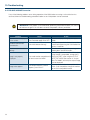
1
MVM-124 (24”)
Operating
Instructions
Multi Format HD Broadcast Monitor
MVM-142 (42”)
MVM-147 (47”)
Important Safety Instructions
1. Please read this manual thoroughly before operating the monitor.
2. Unplug monitor from the wall outlet before cleaning the LCD screen. Do not use liquid cleaners or aerosol
cleaners. Use ONLY a damp cloth provided.
3. Don’t use any unauthorized accessories not recommended by the manufacturer as they may cause
hazards.
4. Don’t operate this monitor near damp or wet surfaces.
5. Use only the recommend manufacturer mounting hardware accessories.
Slots and openings in the cabinet and the back or bottom are provided for
ventilation, and to insure reliable operation of the monitor and to protect it
from overheating, these openings must not be blocked or covered.
6. This appliance should be operated only from the type of power source
indicated on the marking label.
PORTABLE CART WARNING
(symbol provided by RETAC)
If you are not sure of the type of power supplied to your home, consult your
dealer or local power company. For appliance designed to operate from
battery power, refer to the operating instructions.
7. This appliance system is equipped with a 3-wire grounding type plug (a plug having a third (grounding) pin).
This plug will only fit into a grounding-type power outlet. This is a safety feature.
If you are unable to insert the plug into the outlet, contact your electrician to replace your outlet.
Do not ignore the safety purpose of the grounding plug.
8. For added protection for this product during a lightning storm, or when it is left unattended and unused for
long periods of time, unplug it from the wall outlet. This will prevent damage to the product due to lightning
and power-line surges.
9. Do not allow anything to rest on the power cord.
10. Follow all warnings and instructions marked on the appliance.
11. Do not overload wall outlets and extension cords as this can result in fire or electric shock.
12. Do not attempt to service this monitor without a qualified service personnel.
2
FCC Notice
This device complies with Part 15 of FCC Rules.
Operation is subject to the following two conditions:
(1)This device may not cause harmful interference, and (2) this device must accept any interference received,
including interference that may cause undesired operation.
To assure continued compliance, follow the attached installation instruction and do not make any unauthorized
modifications.
Note:
This equipment has been tested and found to comply with the limits for a class B digital device, pursuant to Part
15 of the FCC Rules. These limits are designed to provide reasonable protection against harmful interference in a
residential installation. This equipment generates, uses, and can radiate radio frequency energy, and if not installed
and used in accordance with the instructions, may cause harmful interference to radio communications. However,
there is no guarantee that interference will not occur in a particular installation. If this equipment does cause
harmful interference to radio or television reception, which can be determined by turning the equipment off and on,
the user is encouraged to try to correct the interference by one of the following measures:
• Reorient or relocate the receiving antenna.
• Increase the separation between the equipment and receiver.
• Connect the equipment into an outlet on a circuit different from that to which the receiver is connected.
• Consult the dealer or an experienced radio/TV technician for help.
The user may find the booklet “Something About Interference” available from FCC local regional offices helpful.
Warning:
To assure continued FCC emission limit compliance, the user must use only shielded interface cables when
connecting to host computer or peripheral devices. Also, any unauthorized changes or modifications to this
equipment could void the user’s authority to operate this device.
3
Safety Precautions
WARNING:
CAUTION
RISK OF ELECTRICAL SHOCK
DO NOT OPEN
CAUTION: TO REDUCE THE ELECTRICK SHOCK.
DO NOT REMOVE COVER (OR BACK).
NO USER SERVICEABLE PARTS INSIDE.
REFER SERVICING TO QUALIFIED SERVICE PERSONNEL
The lightning flash with arrowhead symbol,
within an equilateral triangle, is intended to
alert the user to the presence of uninsulated
“dangerous voltage” within the product’s
enclosure that may be of sufficient magnitude
to constitute a risk of electric shock to persons.
The exclamation point within an equilateral
triangle is intended to alert the user to
the presence of important operating and
maintenance (servicing) instructions in the
literature accompanying the appliance.
TO REDUCE THE RISK OF FIRE OR SHOCK HAZARD, DO
NOT EXPOSE THIS EQUIPMENT TO RAIN OR MOISTURE.
TO REDUCE THE RISK OF FIRE OR SHOCK HAZARD,
KEEP THIS EQUIPMENT AWAY FROM ALL LIQUIDS. USE
AND STORE ONLY IN LOCATIONS WHICH ARE NOT
EXPOSED TO THE RISK OF DRIPPING OR SPLASHING
LIQUIDS, AND DO NOT PLACE ANY LIQUID CONTAINERS
ON TOP OF THE EQUIPMENT.
CAUTION:
In order to maintain adequate ventilation, do not install or
place this unit in a bookcase, built-in cabinet or any other
confined space. To prevent risk of electric shock or fire
hazard due to overheating, ensure that curtains and any
other materials do not obstruct the ventilation.
CAUTION:
TO REDUCE THE RISK OF FIRE OR SHOCK HAZARD AND
ANNOYING INTERFERENCE, USE THE RECOMMENDED
ACCESSORIES ONLY.
CAUTION:
This apparatus can be operated at a voltage in the range of
100-240 V AC.
Voltage other than 120V are not intended for U.S.A and
Canada.
THIS EQUIPEMNT MUST BE GROUNDED
To ensure safe operation, the three-pin plug must be inserted
only into a standard three-pin power outlet which is effectively
grounded through normal household wiring. Extension cords
used with the equipment must have three cores and be
correctly wired to provide connection to the ground. Wrongly
wired extension cords are a major cause of fatalities. The
fact that the equipment operates satisfactorily does not imply
that the power outlet is grounded or that the installation is
completely safe.
For your safety, if you are in any doubt about the effective
grounding of the power outlet, please consult a qualified
electrician.
CAUTION:
THE AC RECEPTACLE (MAINS SOCKET OUTLET) SHALL
BE INSTALLED NEAR THE EQUIPMENT AND SHALL BE
EASILY ACCESSIBLE.
TO COMPLETELY DISCONNECT THIS EQUIPMENT FROM
THE AC MAINS, DISCONNECT THE POWER CORD PLUG
FROM THE AC RECEPTACLE.
4
CAUTION:
Operation at a voltage other than 120V AC may require
the use of a different AC plug. Please contact either a local
service center for assistance in selecting an alternate AC
plug.
Notice (U.S.A. only):
This product has a fluorescent lamp that contains a
small amount of mercury. It also contains lead in some
components. Disposal of these materials may be regulated
in your community due to environmental considerations. For
disposal or recycling information please contact your local
authorities, or the Electronics Industries Alliance:
http://www.eiae.org.
Safety Precautions continued
Caution for AC Power Cord
FOR YOUR SAFETY PLEASE READ THE FOLLOWING TEXT CAREFULLY.
Appropriate AC Power Cord must be used in each local area.
FOR CONTINENTAL EUROPE, ETC
Not for use in the U.K.
FOR U.K. ONLY
If the plug supplied is not suitable for your socket outlet,
it should be cut off and appropriate one fitted.
FOR U.S.A. and Canada
Information on Disposal for Users of Waste Electrical & Electronic Equipment (private households)
This symbol on the products and/or accompanying documents means that used electrical and
electronic products should not be mixed with general household waste.
For proper treatment, recovery and recycling, please take these products to designated
collection points, where they will be accepted on a free of charge basis. Alternatively, in some
countries you may be able to return your products to your local retailer upon the purchase of an
equivalent new product.
Disposing of this product correctly will help to save valuable resources and prevent any potential negative effects
on human health and the environment which could otherwise arise from inappropriate waste handling. Please
contact your local authority for further details of your nearest designated collection point.
Penalties may be applicable for incorrect disposal of this waste, in accordance with national legislation.
For business users in the European Union
If you wish to discard electrical and electronic equipment, please contact your dealer or supplier for further
information.
Information on Disposal in other Countries outside the European Union
This symbol is only valid in the European Union.
If you wish to discard this product, please contact your local authorities or dealer and ask for the correct method of
disposal.
CE NOTICE
This is Class B product. In a domestic environment this may cause radio interference in which
case the user may be required to take adequate measures.
The apparatus shall not be exposed to dripping or splashing and no objects filled with liquids,
such as vases, shall be placed on the apparatus.
5
Safety Precautions continued
Important Safety Warnings
Power
Operate unit only on the specified supply voltage.
Disconnect power cord by connector only. Do not pull on cable portion.
Do not place or drop heavy or sharp-edged objects on power cord. A damaged cord can cause fire or electrical
shock hazards. Regularly check power cord for excessive wear or damage to avoid possible fire / electrical
hazards.
Grounding
Ensure unit is properly grounded at all times to prevent electrical shock hazard.
Do not ground the unit to gas lines, units, or fixtures of an explosive or dangerous nature.
Ensure power cord is firmly plugged into AC outlet.
Operation
Do not operate unit in hazardous or potentially explosive atmospheres. Doing so could result in fire, explosion, or
other dangerous results.
Do not allow liquids, metal pieces, or other foreign materials to enter the unit. Doing so could result in fire, other
hazards, or unit malfunction.
If foreign material does enter the unit, turn power off and disconnect power cord immediately. Remove material
and contact authorized service representative if damage has occurred.
Transportation
Handle with care to avoid shocks in transit. Shocks may cause malfunction. When you need to transport the unit,
use the original packing materials or alternate adequate packing.
Circuitry Access
Do not remove covers, panels, casing, or access circuitry with power applied to the unit! Turn power off and
disconnect power cord prior to removal. Internal servicing / adjustment of unit should only be performed by
qualified personnel.
Do not touch any parts / circuitry with a high heat factor.
Capacitors can retain enough electric charge to cause mild to serious shock, even after power is disconnected.
Capacitors associated with the power supply are especially hazardous. Avoid contact with any capacitors.
Unit should not be operated or stored with cover, panels, and / or casing removed. Operating unit with circuitry
exposed could result in electric shock / fire hazards or unit malfunction.
Potential Hazards
If abnormal smells or noises are noticed coming from the unit, turn power off immediately and disconnect power
cord to avoid potentially hazardous conditions. If problems similar to above occur, contact authorized service
representative before attempting to again operate unit.
Consumables
The consumables used in unit must be replaced periodically. For further details on which parts are consumables
and when they should be replaced, refer to the specifications at the end of the Operation Manual. Since the
service life of the consumables varies greatly depending on the environment in which they are used, they should
be replaced at an early date. For details on replacing the consumables, contact your dealer.
Rubber Feet
If this product has come with rubber feet attached by screws, do not insert the screws again without rubber feet
after removing the rubber feet and screws. It may cause damage to the internal circuits or components of the unit.
To install the rubber feet again to the unit, do not use other than the supplied rubber feet and screws.
6
Upon Receipt
Unpacking
MVM units and their accessories are fully inspected and adjusted prior to shipment. Operation can be performed
immediately upon completing all required connections and operational settings.
Check your received items against the packing lists below.
ITEM
QTY
REMARKS
MVM
1
AC Cord
1 set
One AC cord, and one AC cord retaining clip
Operation Manual
1 set
This manual (Includes Layout Editor, Live Viewer, and Web Browser
Operation Manuals, and Layout Editor Tutorial.)
Layout Editor /
Dedicated Viewer
Software
1
CD-ROM
Check
Check to ensure no damage has occurred during shipment. If damage has occurred, or items are missing, inform
your supplier immediately.
Installing AC Cord
1. Securely plug the AC cord into the AC inlet
2. Attach Retaining Clip 1 onto the the AC cord.
7
Contents
MVM............................................................................................................9
1. Prior to Starting........................................................................................................... 9
1-1. Welcome............................................................................................................ 9
1-2. About MVM......................................................................................................... 9
8
1. Prior to Starting
1-1. Welcome
Congratulations! By purchasing MVM Multi Viewer you have entered the world of PLURA BROADCAST and its
many innovative products. Thank you for your patronage and we hope you will turn to PLURA BROADCAST
products again and again to satisfy your video and audio needs.
PLURA BROADCAST provides a wide range of products, from basic support units to complex monitoring
systems, which have been increasingly joined by products for computer video based systems. Whatever your
needs, talk to your PLURA BROADCAST representative. We will do our best to be of continuing service to you.
1-2. About MVM
The MVM Multi Viewer is a four split-screen multi viewer that accepts four inputs (of HD-SDI, SD-SDI, and Analog
Composite signals), resizes the images and display on a single screen. The audio level meter display of embedded
audios of each SDI inputs is provided for monitoring the presence of audio signals. Supported video transmission
over a network also enables to remotely monitor output images. The provided layout editor allows user to freely
arrange the viewer screen layout. The MVM is most suitable for monitoring the system with mixed input of HD-SDI,
SD-SDI and analog composite signals.
• Support for mixed input of HD-SDI, SD-SDI, and Analog composite signals
• Audio level meter display for HD/SD-SDI embedded audio signals (8ch
display)
• DVI connector for high definision image output ( Not applicable when it is
integrated within MVM monitor )
• Video loss detection function
• Analog clock and Digital clock display
• Border display of two selectable colors (red and green) on each channel
frame by external tally intput
• Title display of up to 16 charactors for each input (alphanumeric and
symbol)
• Remote control: Contact inputs, RS-232C/422/485 interface and LAN
interface
• Includes layout editor for enabling users to make any changes to splitscreen patterns from a computer
• SNMP support for monitoring power supply and fan alarm status (Planned
future option)
• Redundant power supply option for ensuring the system reliability
• Video transfer at the maximum frame rate of 60fps (By the dedicated viewer
software MVM Live Viewer)
• The maximum frame rate may not be obtained due to the various factors,
such as size of transmitted image, JPEG compression rate, connected PC or
network environment.
9
2. Quick Start
This chapter describes the basic operations to set up the system for your MVM multi viewer. Refer to the section
given for each operation you may need more details, if necessary.
2-1. Connection
1. Connect the MVM to an AC power source using the supplied accessory cord.
2. Connect the signal source device(s) to the left connector(s) of each set of 1 to 4 HD-SDI/SD-SDI/COMPOSITE
INPUT connectors to supply input signal(s). The right connectors are for active through outputs which we are
not using now.
3. Select Quad input on the MVM monitor.
4. Connect a PC which you are going to use to edit layout by installing the supplied Layout Editor. In the figure
above the shown connection is for the LAN interface that you need for Layout Editor operation.
The system requirements for the PC is shown in the section 16-2. “System Requirements” of the part 3, MVM
Layout Editor of this manual.
10
2. Quick Start continued
2-2. Displaying Image on MVM-1XX Monitor
1. Checking Monitor Display of Output Image
Turn on the power switch on the MVM front panel. When power switch is turned on, the image is displayed on
the MVM-1XX monitor. Is the image displayed on the monitor? Follow the steps given for each case
The output screen size is set to 1920 x 1200 in 60Hz at the factory.
2-3. Connecting MVM and PC over LAN
Connect the MVM and a PC (on which you are going to install the Layout Editor) over a LAN interface. This setting
example shows the case when connecting to the MVM with the default settings. The MVM default settings are
shown below.
ID
ROOT
PASSWORD
0
IP address
192.168.0.1
Subnet mask length
24
Gateway
0.0.0.0
2-3-1. PC Network Settings
The PC network settings need to match that of the MVM. The procedure for making the network settings at the
PC vary depending on the OS, so refer to the OS manual for details.
1. Setting in Windows XP with the default Start menu setting
Click Start on the taskbar, open [Control Panel], and
double-click “Network Connections”. Right-click “Local
Area Connection” icon to open [Properties] window.
Double-clicking “Internet Protocol (TCP/IP)” under
the [General] tab opens the [Internet Protocol (TCP/
IP) Properties] window. Make the settings as shown
in the example below. Make a note of the settings
before changing them in case you need to return the IP
address to its original settings later.
IP address for
PC
192.168.0.yyy (yyy is any number
from 2 to 254 except for the number
set for the MVM unit and the
gateway number. In this example, the
setting is yyy=200.)
Subnet mask
Set to 255.255.255.0.
2. Setting in Windows XP with the Start menu setting changed to Classic
Click Start on the taskbar, select “Settings” -> “Network Connections” and then right-click the “Local Area
Connection” icon to open [Properties] window. Double-clicking “Internet Protocol (TCP/IP)” under the
[General] tab opens the [Internet Protocol (TCP/IP) Properties] window. The settings are then made in the
same way as 1) above. When the settings are completed, click OK, and then close all setting windows.
11
2. Quick Start continued
2-3-2. Installing MVM Layout Editor
Install the MVM Layout Editor on the PC using the supplied CD-ROM. In this section a rough instruction for the
installation is given. For more details see section 16-4. “Installing MVM Layout Editor” in the part 3, MVM Layout
Editor of this manual.
1. Load the supplied Installation CD-ROM into the PC, and open the
CD-ROM drive. Run the file “setup.exe” to start the setup wizard.
2. If [.NET Framework 2.0] or [Windows Installer 3.1] is not installed on your PC, one of the screens shown
below is displayed. Click Accept. If either one is already installed on your PC, any of these screen is not
displayed.
3. When installation of [.NET Framework 2.0] is complete, the screen shown below is displayed requiring a
reboot. Click Yes to reboot your PC.
4. After the setup wizard is restarted, follow the guide to complete the installation.
12
2. Quick Start continued
2-3-3. Starting MVM Layout Editor
1. To start MVM Layout Editor, go to Start > Programs > PLURA and select “MVM Layout Editor”.
2. After the application is started the screen shown below is displayed.
MVM ID Box
3. Enter the IP address, ID and password of the MVM that you wish to connect in the MVM ID boxes at the topright of the main screen. (The factory default of the MVM is as below.)
IP address:
192.168.0.1
ID:
ROOT
Password:
00000
If the entered IP address, ID, or password is not correct,
the error message as shown to the right will be displayed.
Correct the error.
4. Select the layout number as shown below. The selected layout is loaded and displayed in the layout editing
area, and the connection is established. Clicking the Display button next to the Layout No. box will display the
same layout on the monitor screen. You can edit the layout watching the display on the monitor screen.
5. If you are going to edit the layout, see section 19-3. “Editing Layouts” in the part 3, MVM Layout Editor of this
manual for details.
13
3. Panel Descriptions
3-1. Front Panel
1. POWER1 switch
Used to turn the power unit 1 On/Off. Pressing “” side turns power on.
2. FULL (Full screen display button)
Used to set the display in full screen mode.
3. SPLIT (Split screen display button)
Used to set the display in split screen mode.
4. VIDEO SELECT 1 - 4 (Input switches)
In the full screen mode, these buttons are used to select inputs to be displayed.
In the split screen mode, these buttons are used to select the screen layout designed using the Layout Editor.
All four buttons are set to display standard 4-split screen at the factory shipment.
While displaying menus, these buttons are used to navigate menu screens.
5. LOCK (Operation lock button)
Used to disable or enable the operation from the front panel buttons.
• To unlock the operation, press and hold down the button at least 2 seconds.
While displaying menus, this button is used to confirm the settings for each menu item.
6. MENU (Menu button)
Used to open Main menu. While displaying menus, used to return to Main menu or submenu, or
exit Main menu.
• To open Main menu, press and hold down the button at least 2 seconds.
14
3. Panel Descriptions continued
3-2. Rear Panel
1. HD-SDI/SD-SDI/COMPOSITE INPUT 1 - 4
Used to input HD/SD-SDI or analog composite signals (Automatic recognision supported)
The respective right connectors are active through output connectors to output signals from left connectors to
monitors.
• Active through output (for monitors) is available for HD-SDI and SD-SDI.
• No jitter correction. The existing jitter will be carried to the active through output. The total jitter may exceed
the jitter limit of signal standard.
2. DVI IN
Used to connect a DVI-I signals
3. LAN(10/100BASE-T)
Used to control unit or arrange layouts from a PC over a LAN (Ethernet) interface. Transmitting video to a PC
is also possible.
4. LTC
Used to input time code to synchronize the analog or digital clock display. (Hour, minute and second only)
5. TALLY/REMOTE
Used for Tally input to add red or green borders to each channel frame, or remote control on selecting screen
layout by GPI inputs.
6. RS-232C/422/485
Used to connect a PC for remote control on menu operation.
7. HD-SDI/SD-SDI INPUT with Select OUTPUT
Used as two extra inputs to simulate PBM monitors functionality
8. Update Firmware port
9. AC IN (100-240VAC 50/60Hz)
Used for connecting to an AC power source using the supplied accessory cord.
15
4. Connection
4-1. System directly with PC
IMPORTANT: To directly connect PC and MVM, use a crossover LAN cable for the
connection. To connect PC and MVM using a hub or such device, use a straight LAN cable.
4-2. System with Video Transmission
16
4. Connection continued
4-2-1. Network Mode
The system with video transmission has two different network modes such as ‘Unicast mode’ and ‘Multicast
mode’. For the mode settings, see section 7-2. “SYSTEM” and 7-3. “LAN”.
4-2-1-1. UNICAST Mode
The UNICAST mode using TCP/IP protocol supports the system that can provide video output to one monitor by
MVM Live Viewer.
4-2-1-2. MULTICAST Mode
The MULTICAST mode using IP multicast supports the system that can provide video outputs to multiple monitors
through the MVM as shown below.
IMPORTANT: Due to the UDP protocol used in MULTICAST mode, the video output may not
be updated at the packet loss which occurs under the unstable network condition.
17
5. Operations
5-1. Operation at Startup
After the power is turned on, operation resumes from the last screen before the power was turned off. If a menu
screen was displayed when the unit was turned off, operation resumes from the status before the menu screen.
5-2. Data Initialization
Although initialization is normally not required, you can restore the MVM factory settings by the data initialization
when the previous data is no longer needed such as after relocation or system modification. Turn on the power
while holding down the MENU button. “MEMORY CLEAR” appears on the monitor screen and the setting data
will be initialized.
5-3. Displaying Full Screen
To display your desired channel in full screen, press the FULL button and then press the VIDEO SELECT 1 to 4
buttons. For instance, to view channel 3 in full screen, press the FULL button and then press the SELECT 3 button.
IMPORTANT: The image distortion occurs while switching layouts. A black screen is shown
for channels with no input signals.
5-4. Displaying Split Screens
To display split screens, press the SPLIT button. Pressing a VIDEO SELECT button while displaying split screen will
change the displayed split screen layout to another layout.
IMPORTANT: The image distortion occurs while switching layouts. A black screen is shown
for channels with no input signals.
18
5. Operations continued
5-5. REMOTE/TALLY
MVM can be remotely controlled using contact inputs to the TALLY IN/REMOTE connector on the rear panel. The
connector is also provided with pins for external tally inputs that enable to display two color borders on video frames.
Connector pin assignments (25-pin, D-sub female) Inch screws
Pin no.
Function
Description
1
IN1 TALLY (Red)
INPUT1 TALLY border (Red) display
2
IN2 TALLY (Red)
INPUT2 TALLY border (Red) display
3
IN3 TALLY (Red)
INPUT3 TALLY border (Red) display
4
IN4 TALLY (Red)
INPUT4 TALLY border (Red) display
5
IN1 TALLY (Green)
INPUT1 TALLY border (Green) display
6
IN2 TALLY (Green)
INPUT2 TALLY border (Green) display
7
IN3 TALLY (Green)
INPUT3 TALLY border (Green) display
8
IN4 TALLY (Green)
INPUT4 TALLY border (Green) display
9
FULL 1
INPUT1 Full screen display
10
FULL 2
INPUT2 Full screen display
11
FULL 3
INPUT3 Full screen display
12
FULL 4
INPUT4 Full screen display
13
+5V
+5V output (maximum 200mA DC)
14
GND
GND
15
USER1
Preset layout 1
16
USER2
Preset layout 2
17
USER3
Preset layout 3
18
USER4
Preset layout 4
19
ADJ_IN
Time adjustment input
20
ADJ_OUT
Time adjustment output
21
FAN_ALARM
Fan alarm output
22
NC
Do not use.
23
NC
Do not use.
24
NC
Do not use.
25
NC
Do not use.
Compatible connector: DB-25PF-N(JAE)
Cover:
DB-C4-J11-S1(JAE)
Signal standard:
Make contact, TTL level negative logic pulse
IMPORTANT: The input signal pulse width should be 100ms or more. The input signal
interval should also be 100ms or more.
19
5. Operations continued
5-5. REMOTE/TALLY continued
Input Connector
The figure at right depicts the MVM circuit for
each input pin.
Output Connector
The figure at right depicts the MVM circuit for each
output pin. Outputs 5V TTL level alarm signal.
5-5-1. Control using REMOTE Connector
Control via REMOTE connector operates the same as control from front panel buttons. Commands from both
REMOTE connector and front panel buttons are accepted at the same time.
5-5-2. ADJ_IN (External Time Adjustment Input)
Time adjustment made by the falling edge of the external pulse input (pulse width 100ms or more) is shown below.
1. When second digit displays 1 to 29 -> Correct to 0 second
2. When second digit displays 30 to 59 -> Correct to 0 second and add 1 minute
5-5-3. ADJ_OUT (External Time Adjustment Output)
Outputs a pulse signal (500ms) at the interval set at the ADJUST in the [SYSTEM].
IMPORTANT: ADJ_OUT pin outputs a pulse signal at the set interval triggered by the
internal clock. ADJ_IN pin does not supply buffered output.
20
6. Screen Display
6-1. Full Screen
The display mode can be selected from three options. See section 18-2-1. “System” in the part 3, MVM Layout
Editor of this manual for details on setting display mode.
MODE1
Displays the title and audio level meters without
overlapping on the video image. The aspect ratio of the
input signal is retained. The example (right) is displaying
4:3 material in 16:9 display mode.
MODE2
Overlaps the title and audio level meters on the video
image. The aspect ratio of the input signal is retained.
The example (right) is displaying 16:9 material in 4:3
display mode.
MODE3
Overlaps the title and audio level meters on the video
image. The aspect ratio of the input signal is not
retained, and the image is displayed to fill the selected
display mode screen.
21
6. Screen Display continued
6-2. Split Screen
The split screen layout can be freely arranged using the supplied Layout Editor.
1. Image Display Window
Windows to display each channel input. Display mode within the windows varies depending on the settings of
display mode. See section 18-2-1. “System” in the part 3, MVM Layout Editor of this manual for details.
If MODE1 or MODE2 is selected
Maximizes the image to best fit the window while retaining the aspect ratio.
If MODE3 is selected
Maximizes the image to best fit the window without retaining the aspect ratio.
2. Title display
Titles of each channel input. Titles can be displayed either within or outside the windows.
3. Audio Level Meter display
Audio level meters of each channel input. Audio level meters can be displayed either within or outside the
windows.
4. Border display
Border display is available on each window frame. Line width of border can be changed using Layout Editor.
See section 18-3-1. “Border” in the part 3, MVM Layout Editor of this manual for details.
5. Tally display
Two tally inputs (red and green) are available for each channel input. Tally is displayed outside the border.
Tally display color for simultaneous inputs of red tally and green tally can be selected from red or orange. See
section 18-2-3. “Tally” in the part 3, MVM Layout Editor of this manual for details.
22
6. Video loss display
The video loss alarm is displayed when video signal is lost. The display time length for the alarm can be
changed using Layout Editor. See section 18-2-4. “Video Loss” in the part 3, MVM Layout Editor of this
manual for details.
6. Screen Display continued
6-3. Crop
The effective pixel area (where picture exists) of the input display can be set. The black area produced by
converting images to 4:3 or 16:9 can be reduced or eliminated, and the images can be enlarged and displayed to
best fit the output screen. See section 18-2-6. “Crop” in the part 3, MVM Layout Editor of this manual for details
on crop settings.
23
6. Screen Display continued
6-4. Audio Level Meter
Audio level meter for up to 8 channels can be displayed for each HD-SDI and SD-SDI input. For the details on
audio level meter settings, see section 19-3-8. “Changing Display Position of Audio Level Meters” in the part 3,
MVM Layout Editor of this manual.
1. Peak Level
Peak level can be set in the range of -30dBFS to 0dBFS.
The level bar rises above the peak level, the exceeded part is displayed in red.
2. Reference Level
Reference level can be set in the range of -60dBFS to -1dBFS.
The level bar rises above the reference level, the exceeded part is displayed in yellow.
The bar below the reference level is displayed in green.
3. Peak Hold
Shows the maximum level reached in the set length of the time.
If the higher peak is reached, the display changes to indicate the higher peak. When the peak hold time is
elapsed without reaching to any higher peak, it displays the current audio level. If the peak hold time is set to
0 sec, no peak hold display is provided.
4. Audio data indicator
Indicates the presence of audio data.
When there is an audio input, it is displayed in green. When there is no audio input, it is displayed in black.
HD-SDI: Detects active audio data, and indicates the presence or absence of audio data.
SD-SDI: Detects active audio data or audio data of above -60dBFS, and indicates the presence or
absence of the data.
24
7. Menu Operations
Submenus can be accessed from the main menu for completing various settings.
7-1. Main Menu Screen
Press and hold down the MENU button for at least two seconds to display the MAIN MENU.
MAIN MENU
1 SYSTEM
2 LAN
3 SERIAL
4 VERSION
Operating Procedure
Button
Action
Moves the cursor up.
Moves the cursor down.
ENTER
Accesses the submenu of the selected item.
Setting items
Item
Setting details
Reference
Input signal format settings
1 SYSTEM
Network mode settings
ID and Password settings
7-2.SYSTEM
Date and time settings
2 LAN
Network settings
3 SERIAL
Serial interface settings
4 VERSION
Version display
7-3.LAN
7-4.SERIAL
7-5.VERSION
25
7. Menu Operations continued
Menu Diagram
26
7. Menu Operations continued
7-1. Main Menu Screen
On the MAIN MENU, move the cursor to [SYSTEM] and press the ENTER button. The SYSTEM screen is
displayed as shown below.
SYSTEM
INPUT FORMAT
NETWORK MODE
ID
PASSWORD
ADJUST
TIME STANDARD
2007-01-01
AUTO
UNICAST
ROOT
00000
1/MINUTE
INTERNAL
00:00:00
*The settings in the figure above are the factory defaults.
Operating Procedure
Button
Action
Moves the cursor up.
Moves the cursor down.
Changes the setting item value. (Reverse)
Changes the setting item value. (Forward)
MENU
Returns from SYSTEM menu to MAIN MENU, or from ID, PASSWORD, or Time
setting mode to SYSTEM menu.
ENTER
Accesses INPUT FORMAT submenu or enter input mode for ID, PASSWORD, or Time
when the cursor is on those items. Returns from ID, PASSWORD, or Time input mode
to SYSTEM menu.
Setting items
Item
INPUT FORMAT
Setting range
Setting details
AUTO
Automatically recognizes input signal formats.
MANUAL
Accepts manually set signal formats only.
NETWORK MODE
MULTICAST
Sets to Multicast mode.
UNICAST
Sets to Unicast mode.
ID
8 alphanumeric characters
Used to set ID for the connection with PC over a LAN.
ID of 8 space characters is not authenticated.
PASSWORD
00000 - 99999
Used to set Password for the connection with PC over
a LAN.
ADJUST
MINUTE/HOUR/DAY
Sets the interval of time adjustment pulse output that is
output from TALLY/REMOTE connector pin 20. (every
minute/hour/day)
INTERNAL
Uses internal clock signal.
LTC
Uses LTC time code signal.
TIME STANDARD
Year: 2000 - 2099
Month: 01 - 12
Date and Time
Day: 01 - 31
Time: 00 - 23
Used to set the current time.
Minute: 00 - 59
Second: 00 - 59
27
7. Menu Operations continued
7-1. Main Menu Screen
On the SYSTEM screen, move the cursor to [INPUT FORMAT] and press the ENTER button. The INPUT FORMAT
screen is displayed as shown below. On the INPUT FORMAT screen, formats of input signals can be seen and set.
INPUT FORMAT
CH1
CH2
CH3
CH4
1080/59.94i
720/59.94p
525/60
PAL
Operating Procedure
Button
Action
Moves the cursor up. (Only in manual mode)
Moves the cursor down. (Only in manual mode)
Changes the setting item value. (Reverse) (Only in manual mode)
Changes the setting item value. (Forward) (Only in manual mode)
MENU
Returns to SYSTEM menu.
ENTER
Accesses INPUT FORMAT submenu or enter input mode for ID, PASSWORD, or Time
when the cursor is on those items. Returns from ID, PASSWORD, or Time input mode
to SYSTEM menu.
Setting items
Item
Setting range
1080/59.94i, 1080/50i
CH1 - 4
720/59.94p, 720/50p
525/60, 625/50
28
Setting details
*525/60, and 625/50 represent SD-SDI signals. NTSC,
and PAL represent analog composite signals.
Accepts manually set signal formats only.
Sets to Multicast mode.
7. Menu Operations continued
7-3. LAN
On the MAIN MENU screen, move the cursor to [LAN] and press the ENTER button. The LAN screen is displayed
as shown below. On the LAN screen network setting can be seen and changed.
LAN
IP ADDRESS
192.168.0.1
MASK LENGTH
24BIT
MULTICAST ADDRESS 239.255.0.0
MULTICAST PORT
2100
GATEWAY
0.0.0.0
MAC ADDRESS 00-10-B 1-02-6x-xx
Operating Procedure
*The settings in the figure above are the factory defaults.
Button
Action
Moves the cursor up.
Moves the cursor down.
Changes the setting item value. (Reverse)
Changes the setting item value. (Forward)
ENTER
Entering value while pressing down ENTER will change the value of the tens digit.
(For MULTICAST PORT, changes the value of the thousands digit.) (Except MASK
LENGTH)
MENU
Returns to MAIN menu.
IMPORTANT: If you change the value for the items other than MULTICAST ADDRESS and
MULTICAST PORT, a warning message appears to require the restart of the unit. Whenever
you have changed these settings, power off the MVM once and power on again.
Setting items
Item
Setting range
Setting details
IP ADDRESS
0.0.0.0 - 255.255.255.255
(except 0.0.0.0, and 1.0.0.0)
Used to set IP ADDRESS. This setting is necessary for
the communication over a LAN interface. Please consult
with your system administrator if using in your existing
network.
MASK LENGTH
0 - 31
Used to set subnet mask length for the device.
MULTICAST
ADDRESS
224.0.0.0 - 239.255.255.255
(except 224.0.0.0 224.0.0.255)
Used to set multicast address to use in multicast mode.
MULTICAST PORT
1024 - 65535
Used to set multicast port for the connection in
multicast mode. *This setting is not required for the
connection in unicast mode.
GATEWAY
0.0.0.0 - 255.255.255.255
If your using network does not have a gateway, this
setting is not required.
MAC ADDRESS
Do not change
Displays the MAC addresses of the device. The value
cannot be changed.
IMPORTANT: If the MENU button is pressed when the entered value is invalid, an error
message will be displayed. Press or button to clear the error and correct the invalid value.
29
7. Menu Operations continued
7-4. SERIAL
On the MAIN MENU screen, move the cursor to [SERIAL] and press the ENTER button. The SERIAL screen is
displayed as shown below.
SERIAL
SERIAL SELECT
BAUDRATE
PARITY
SERIAL ID
RS-232C
9600
NONE
0
Operating Procedure
Button
Action
Moves the cursor up.
Moves the cursor down.
Changes the setting item value. (Reverse)
Changes the setting item value. (Forward)
MENU
Returns to MAIN menu.
ENTER
Accesses INPUT FORMAT submenu or enter input mode for ID, PASSWORD, or Time
when the cursor is on those items. Returns from ID, PASSWORD, or Time input mode
to SYSTEM menu.
Setting items
Item
Setting range
Setting details
SERIAL SELECT
RS-232C/RS-422/RS-485
Selects interface to be used.
BAUDRATE
9600/19200/38400
Sets baud rate.
PARITY
NONE/ODD/EVEN
Sets parity.
SERIAL ID
0 - 31
Sets serial ID for the device.
IMPORTANT: If you are using RS-422 or RS-485, you must adjust jumper switch settings on
MVM main unit. See section 9. “RS-232C/422/485 Interface” for details on adjusting switches.
30
7. Menu Operations continued
7-5. VERSION
On the MAIN MENU screen, move the cursor to [VERSION] and press the ENTER button. The VERSION screen is
displayed as shown below. On the VERSION screen, the version information of MVM can be seen.
VERSION
SOFT
01.00
HARD1
01.00
HARD2
01.00
HARD3
01.00
*The settings in the figure above are the factory defaults.
Operating Procedure
Button
Action
Button
Action
MENU
Returns to MAIN menu.
31
8. Output Size Test Mode
This mode is used to verify that the connected monitor can display the output image in the format set on the MVM.
Turn the power on while pressing the LOCK button, the screen shown below will be displayed in the format used
last time the power was turn off. The LEDs on the front panel are also turned on according to the format selected
for the output. The LED indication details are shown in the table below. The factory default is set to 1920x1200/60.
OUTPUT SIZE TEST MODE
1920*1200/60
H PIXELS OFFSET
0
Operating Procedure
Button
Action
Changes the output resolution. (Reverse)
Changes the output resolution. (Forward)
Changes the value of H PIXELS OFFSET. (Reverse) *Minimum -4 pixels
Changes the value of H PIXELS OFFSET. (Forward) *Maximum 4 pixels
ENTER
Changes the output frequency.
MENU
Resumes start-up of the MVM. (The setting of the output frequency is stored.)
Assessing Status
If the connected monitor does not display the image in the format set on the MVM, verify the format actually output
by the LEDs on the front panel. See the table below for the verification. If you need to change the format for the
display according to the test result, change the format using the Layout Editor.
1. Output resolution
Setting order
Resolution
3
4
LOCK
MENU
1
1280 x 1024
Flash
Flash
Flash
Flash
2
1360 x 768
Flash
Flash
Flash
Lit
3
1600 x 1200
Flash
Flash
Lit
Flash
4
1920 x 1200
Flash
Flash
Lit
Lit
5
1440 x 900
Flash
Lit
Flash
Flash
6
1680 x 1050
Flash
Lit
Flash
Lit
7
1920 x 1080
Flash
Lit
Lit
Flash
8
1280 x 720
Flash
Lit
Lit
Lit
Setting order
Frequency
FULL
SPLIT
1
2
1
60Hz
Flash
Flash
Flash
Flash
2
59.94Hz
Flash
Flash
Flash
Lit
3
50Hz
Flash
Flash
Lit
Flash
2. Output Frequency
IMPORTANT: If the image of your desired format is not properly displayed, change the “H
PIXELS OFFSET” value and check if the monitor can display the image. Normally set H PIXELS
OFFSET to 0 for operating the MVM.
32
9. RS-232C/422/485 Interface
The factory default is set to RS-232C interface. To change the interface from RS-232C to RS-422 or RS-485, or
to change the termination ON/OFF setting, change the settings at [SERIAL SELECT] in the SERIAL menu and the
jumper switches in the main unit. See sections 7-4. “SERIAL” and 9-1. “Changing RS-422/RS-485 or Termination”.
Once the setting is changed to RS-422 or RS-485, the same adjustments are required to return to RS-232C
again. The command format for the RS-422 interface and RS-485 interface is common.
Item to change
Original
RS-232C
RS-485
RS-422
Adjustments made for
Change to
Menu setting at
SERIAL SELECT
Jumper switches
RS-485
Required
Required
RS-422
Required
Required
RS-232C
Required
Not required
RS-422
Required
Required
RS-232C
Required
Not required
RS-485
Required
Required
CAUTION: Do not access internal cards or make connections with the unit powered ON.
Always power OFF all connected units / disconnect power cords prior to accessing interior.
The repair or adjustment that requires opening the unit should only be done by qualified
technical personnel.
9-1. Changing RS-422/RS-485 or Termination
To change the interface from/to RS-422/RS-485 or to change the termination ON/OFF setting, remove the main
unit top panel, and adjust the jumper switch settings on the SUB card inside.
1. Remove screws from the back panel of the monitor.
2. Lift and completely remove the back panel.
3. Change the settings at JP3 and JP4 to switch interface to RS-422 or RS-485. To change the termination ON/
OFF setting, change the settings at JP1 and JP2.
Interface to use
JP3
JP4
RS-422
1-2
1-2
RS-485
2-3
2-3
Termination
JP1
JP2
ON
1-2
1-2
OFF
2-3
2-3
4. Return the top panel in place and secure with screws.
5. Power on the MVM. Open [SERIAL] Menu screen, and select RS-422 or RS-485 at [SERIAL SELECT].
IMPORTANT: Before performing the above operation to change interface selection,
disconnect the serial cable from the connector on the rear panel. The operations as an
example below may cause unit a malfunction. (E.g.) Switching from RS-232C to RS-485 or
RS-422 while a cable is connected for RS-232C on the rear panel.
To return to RS-232C interface from RS-422 or RS-485 interface, only the menu setting for SERIAL SELECT must
be changed to RS-232C. No need to change the jumper switch settings at JP1 - JP4 on SUB card.
33
9. RS-232C/422/485 Interface continued
9-2. RS-232C/422/485 Connector
RS-232C connector pin assignment (9-pin, D-sub male)
Pin no.
Signal
In/Out
Description
1
-
2
TXD
Output
Transmit data
3
RXD
Input
Receive data
4
DSR
Input
Data set ready
5
GND
6
DTR
Output
Data terminal ready
7
CTS
Input
Clear to send
8
RTS
Output
Request to send
9
-
Unassigned
Signal ground
Unassigned
RS-422 connector pin assignment (9-pin, D-sub male)
Pin no.
Signal
In/Out
Description
1
-
2
RX+
Input
Receive data
3
TX-
Output
Transmit data
4
-
Unassigned
5
GND
Signal ground
6
-
Unassigned
7
RX-
Input
Receive data
8
TX+
Output
Transmit data
9
-
Unassigned
Unassigned
RS-485 connector pin assignment (9-pin, D-sub male)
34
Pin no.
Signal
In/Out
Description
1
NC
2
TX/RX+
3
NC
Unassigned
4
NC
Unassigned
5
GND
Signal ground
6
NC
Unassigned
7
TX/RX-
8
NC
Unassigned
9
NC
Unassigned
Unassigned
In/Out
In/Out
Transmit/Receive data
Transmit/Receive data
9. RS-232C/422/485 Interface continued
Serial communication standard
Transmission mode
Asynchronous, Full-duplex (RS-232C, RS-422), Half-duplex (RS-485)
Baud rate
Select from 9600, 19200, or 38400[bps]
Data length
8 [bit]
Stop bit
1 [bit]
Parity
Select from NONE, ODD, or EVEN
Flow control
None
IMPORTANT: DSR/DTR and RTS/CTS are looped back in the MVM. Use a RS-232C straight
cable or 422 straight cable to connect another device such as a PC.
9-3. RS-232C Connection Example
MVM
PC
Pin no.
Signal
Pin no.
Signal
1
Not used
1
Not used
2
TxD
2
RxD
3
RxD
3
TxD
4
DSR
4
DTR
5
GND
5
GND
6
DTR
6
DSR
7
CTS
7
RTS
8
RTS
8
CTS
9
Not used
9
Not used
Case
9-pin D-sub
male
Case
9-pin D-sub
female
IMPORTANT: Use straight cables. (The wiring and connector depend on the type of
computer.) DSR/DTR and RTS/CTS are looped back in the MVM.
35
10. Troubleshooting
9-2. RS-232C/422/485 Connector
If any of the following problems occur during operation of the MVM, before assuming a unit malfunction has
occurred, follow the troubleshooting procedures below to see if the problem can be corrected.
IMPORTANT: If the problem is not corrected by performing the procedures below, turn the unit
off and then on again. If this still does not correct the problem, contact your dealer.
Problem
Check
No information is displayed
on the screen.
Are all information display settings
in the Parameter page set to ON?
Check the display settings by the Layout
Editor
Unable to operate front
panel buttons.
Is the LOCK button flashing?
Front panel operation is locked. Cancel the
switch lock by pressing the LOCK button for
at least 2 seconds.
I want to restore the default
settings.
36
Action
Turn the unit power on while pressing and
holding down the MENU button.
Image is not properly
displayed.
If not, change the format of the MVM output .
If the monitor is compatible, change the H
Is the used monitor compatible with PIXELS OFFSET value using the OUTPUT
the format set on the MVM?
SIZE TEST MODE (See section 8. “Output
Size Test Mode”) and verify the output image
can be displayed.
Image noise appears.
Is the output frequency (vertical
frequency) set to 50Hz?
Check that the monitor is compatible with
50Hz. If not compatible, change the monitor
to the 50Hz compatible monitor.
11. Specifications and Dimensions
11-1. Specifications
TV Standard
HD:
1080/60i, 1080/59.94i, 1080/50i, 720/60p, 720/59.94p, 720/50p
SD:
525/60 (NTSC), 625/50 (PAL)
4 inputs of any inputs below (Mix input, asynchronous acceptable)
Video Input
LTC Input
HD-SDI:
1.485Gbps or 1.485/1.001Gbps 75Ω BNC
SD-SDI:
270Mbps 75Ω BNC
Analog composite:
1.0V(p-p) 75Ω BNC
1 input
SMPTE time code
appr. 1.0Vp-p within ±6dB
DVI output (Outputs Digital and Analog outputs at the same time.)
DVI-I connector
Video Output
1 output
Resolution:
1920x1200, 1600x1200, 1280x1024, 1360x768
1440x900, 1680x1050, 1920x1080, 1280x720
Frequency:
Refer to the table below.
*No input/output frame rate converter. Frame rate difference between input and output results
the repeat frame or drop frame.
DVI / Analog RGB output frequency chart (When H PIXEL OFFSET is set to 0.)
1920x1200
Mode Hz
60
59.94
1600x1200
50
H(Horizontal) kHz 74.06 74.05 61.90
V(Vertical) Hz
59.96 59.95 50.00
60
59.94
50
59.94
75
74.93 61.91 63.98 63.91 52.87 47.71 47.66 39.66
60
59.94 50.01 60.02 59.95 50.02 60.02 59.95 50.01
1680x1050
50
60
59.94
59.94
50
60
1920x1080
50
H(Horizontal) kHz 55.96 56.02 46.47 65.26 65.26 54.15
V(Vertical) Hz
60
1360x768
60
1440x900
Mode Hz
1280x1024
60
67.5
59.91 59.97 50.03 59.93 59.93 50.01
60
59.94
59.94
50
1280x720
50
60
59.94
50
67.44 56.25
45
44.95
37.5
59.95
60
59.93
50
50
*60Hz mode is most similar to the VESA standard.
Active loop
through output
(for a monitor)
Quantization
I/O Delay
Screen Display
Types
Title display
Tally Indication
Audio Level
Meters
Time Display
HD-SDI:
1.485Gbps or 1.485/1.001Gbps
SD-SDI:
270Mbps 75Ω BNC
* Available only when input is either HD-SDI or SD-SDI.
* No jitter correction. The jitter in the input will be carried to the active loop through output. The
total jitter may exceed the jitter limit of signal standard.
8 bit
1 - 2 frames
Full screen, User customized layout
Character capacity:
Max. 16 characters x 1 line for each input channel
Character types:
Frame:
Alphanumeric characters and symbols
Red or Green per input. (Red or Umber selectable for the display at
the simultaneous inputs of red and green tallies.)
8 embedded audio channels per input
* Embedded audio signals are not passed through.
Real-time display (provided with the internal clock )
*Accuracy within ±10 seconds per month (at 25°C)
37
11. Specifications and Dimensions continued
11-1. Specifications
RS-232C/RS-422/RS-485: 9-pin D-sub male, 1 port
9,600/19, 200/38, 400bps, data length 8bit, stop bit 1bit, parity NONE/ODD/
EVEN
Baud rate:
25-pin D-sub female *Shared use with REMOTE IN
TALLY IN:
4 inputs x 2colors (red or green border display)
TTL negative logic pulse level or Make contact
Interfaces
25-pin D-sub female *Shared use with TALLY IN
REMOTE IN:
Control over switching channels or display modes of full screen or split screen
TTL negative logic pulse level or Make contact
LAN:
10Base-T/100Base-TX, RJ-45 (Category 5), 1 port
Video
transmission:
Layout Editor
Edit size and position of windows in split screen
Temprature/
Humidity
0°C - 40°C, 30% - 90% (no condensation)
Backup battery
Internal lithium battery (to maintain time)
43VA (42W) at 100VAC
Consumption
53VA (40W) at 200VAC
Power
100VAC - 240VAC ±10%, 50Hz/60Hz
Weight
5.5kg (with redundant power supply option installed)
Dimentions
430 (W) x 44 (H) x 400 (D)mm, EIA1RU
Accessories
Operation Manual, AC cord, Rack mount brackets, CD-R (Layout Editor, Live Viewer)
• SNMP compatible (for Power/Fan status observation)(future release)
Option
Consumables
38
Compress and transmit DVI/Analog RGB output and image, JPEG
compression
• Redundant power supply
Power unit:
Replace every 4 years (at room temperature)
Fan:
P1399 (front and rear)
Replace every 5 years (at room temperature)
Battery:
CR2450
Replace every 7 years (at room temperature)
11. Specifications and Dimensions continued
11-1. Specifications
39
40
RS-232C/422/485/
LAN COMMAND
Version 2.0 - Higher
41
12. Communication Setting
12-1. RS-232C / 422 / 485 Interface Communication Standards
The communication standards when connecting the unit to a serial controller via RS-232C, RS-422 or RS-485 are
as follows.
Transmission speed
9600bps, 19200bps or 38400bps
Data length
8 [bit]
Stop bit
1 [bit]
Parity
None, Odd, Even
X parameter (flow control)
None
12-2. LAN Interface Communication Setting
The communication standards when connecting the unit to a serial controller via LAN are as follows.
Communication Protocols
Application Layer
Original protocol described in this appendix manual
Transport Layer
TCP, UDP
Network Layer
IP, ICMP, ARP, RARP
Network Interface Layer
Ethernet (CSMA/CD, 10BASE-T/100BASE-TX)
Network Setting
Item
Default Setting
IP address
192.168.0.1
Subnet mask
(Mask length)
24
Multcast address
239.255.0.0
Multcast port
2100
Gateway
0.0.0.0
Port number
-
MAC address
Set at the factory
Setting Range
[0-255].[0-255].[0-255].[0-255]
(Except 0.0.0.0 and 1.0.0.0)
0-31
[224-239].[0-255].[0-255].[0-255]
(Except 224.0.0.0 to 224.0.0.255)
1024 to 65535
[0-255].[0-255].[0-255].[0-255]
Gateway (0.0.0.0) means the default gateway is not set.
2010: Used to send and receive commands
2000: Used to receive image data
(Cannot be changed)
(Cannot be changed.)
NOTE: The network settings above are made in the LAN menu in MVM. See “LAN menu” in
the MVM Operation Manual for details.
42
12. Communication Setting continued
12-3. Notes on the LAN Interface
1. IP address, Subnet mask, Gateway and Port number settings must be set to suit your network system.
2. Consult your system administrator before setting IP address, Subnet mask, Gateway and Port number to
avoid troubles, if configuring the system in an existing LAN.
3. The MVM cannot establish connections to multiple PCs via LAN.
4. Release the port on the MVM when terminating the control from the PC, so that the MVM can establish a
connection again to the PC or to another PC.
5. It takes approxmately 10 seconds to release port2000 on MVM after port2000 (for image data transmission) is
released on the computer, and during this period you cannot establish a connection.
6. The command port (port2010) automatically closes the socket connection to the computer if the socket
connection is left unused for 5 seconds.
State Transition Diagram of MVM
43
13. Command Protocol Format
All command contents are transmitted and received in ASCII code. Follow each format to make and send
message commands. The command formats are as shown in the following pages.
13-1. Commands Formats for RS-232C, RS-422 and LAN (without Password)
Command Format
Command code + Command parameter + CR + LF
(3 byte)
(Bytes specified for each parameter)
(Works without LF as well)
(Ex.) When sending a command to display in full screen
Byte
Parameter
Command
1-3
Command code
SDF
4
Reserve
0
5-6
Input channel
01-04
7
8
End code
Description
Fixed to "0"
Channel no. 1-4
CR
LF
NOTE: The MVM sends a response or a message when receiving a command. Do not send
the next command before receiving the response or the message transmitted by the MVM;
Otherwise, the command cannot be read properly.
44
13. Command Protocol Format continued
13-2. Commands Formats for RS-485
The ID header is located in front of the Command code. The ID number specifies the ID of MVM (00-31) to be
controlled. The ID number is set in the menu of MVM.
Command Format
I + ID number + Command code + Command parameter + CR + LF
(2 byte)
(3 byte)
(Bytes specified for each parameter)
(Works without LF as well)
(Ex.) When sending a command to display in full screen
Byte
1
2-3
Parameter
ID header
4
5
Command
I
00-31
Command code
D
F
7
Reserve
0
8-9
Input channel
01-04
11
Fixed to "0"
S
6
10
Description
End code
Fixed to "0"
Channel no. 1-4
CR
LF
NOTE: The MVM sends a response or a message when receiving a command. Do not send
the next command before receiving the response or the message transmitted by the MVM.
Otherwise, the command cannot be read properly.
Do not use the same ID number for two or more devices in an RS-485 system. If there
exists any device which has the same ID number as MVM in the RS-485 system, the MVM
connection does not work properly.
45
13. Command Protocol Format continued
All command contents are transmitted and received in ASCII code. Follow each format to make and send
message commands. The command formats are as shown in the following pages.
13-3. Commands Formats for LAN (with Password)
Command Format
ID number + Password + Command code + Command parameter + CR + LF
(n byte)
(5 byte)
(3 byte) (Bytes specified for each parameter)
(Works without LF as well)
(Ex.) When sending a command to display in full screen
Byte
Parameter
Command
1
Number of characters for ID
1-8
2 to n
ID
Description
1- 8 characters
ID set for the controlled MVM.
n+1
1-9
1st digit
n+2
1-9
2nd digit
1-9
3rd digit
n+4
1-9
4th digit
n+5
1-9
5th digit
n+6
S
n+3
n+7
Password
Command code
n+8
D
F
n+9
Reserve
0
n+10 to
n+11
Input channel
01-04
n+12
n+13
End code
Fixed to "0"
Channel no. 1-4
CR
LF
NOTE: The MVM sends a response or a message when receiving a command. Do not send
the next command before receiving the response or the message transmitted by the MVM.
Otherwise, the command cannot be read properly.
46
13. Command Protocol Format continued
13-4. Response Message Format
Normal end
Messages in the following format are returned after normal reception and processing.
Byte
Parameter
Command
1-2
Message code
OK
3
4
End code
Description
"OK"
CR
LF
Abnormal end
If something prevents commands from being issued normally, messages in the following format are returned.
Byte
Parameter
Command
1-3
Message code
ERR
4-6
Error code
8
End code
"ERR"
1
Command Error
2
Command Length Error
3
Parameter Range Error
4
MVM is in menu mode.
5
Setting not-available (function not-installed)
006-999
7
Description
Future use
CR
LF
47
14. Control Commands
14-1. Full Screen Display
Displays the specified channel in full screen.
With normal reception and processing, the response message is “OK.”
“ERR004” message is returned during MENU screen display.
Byte
Parameter
Command
1-3
Command code
SDF
4
Reserve
0
5-6
Input channel
01-04
7
End code
8
Description
Fixed to "0"
Channel no. 1-4
CR
LF
14-2. Layout Display
Displays the specified layout.
With normal reception and processing, the response message is “OK.”
“ERR004” message is returned during MENU screen display.
Byte
Parameter
Command
1-3
Command code
SDS
4
Reserve
0
5-6
Layout
01-04
7
8
End code
Description
Fixed to "0"
Layout no. 1-4
CR
LF
14-3. Frame Rate Setting for Video Transmission
Sets a frame rate for video transmission.
With normal reception and processing, the response message is “OK.”
Byte
Parameter
Command
1-3
Command code
SNF
Description
4
0
1
1fps (60Hz, 59.94Hz)
1fps (50Hz)
2
5fps (60Hz, 59.94Hz)
4fps (50Hz)
10fps (60Hz, 59.94Hz)
8fps (50Hz)
4
15fps (60Hz, 59.94Hz)
12fps (50Hz)
5
30fps (60Hz, 59.94Hz)
25fps (50Hz)
6
60fps (60Hz, 59.94Hz)
50fps (50Hz)
3
5
6
Frame rate
End code
0fps (No video transmission)
CR
LF
NOTE: Video transmission starts when “Frame rate” is set other than “0.” To stop video
transmission, set “Frame rate” to “0.”
In some cases video cannot be sent by the specified frame rate due to the video resolution,
JPEG compression ratio, PC performance or the network environment. In this case, increase
the JPEG compression ratio to reduce the data size.
48
14. Control Commands Format continued
14-4. JPEG Compression Setting for Transmission
Sets a JPEG compression ratio for video transmission.
With normal reception and processing, the response message is “OK.”
Byte
Parameter
Command
1-3
Command code
SNJ
4
5
6
JPEG compression ratio
End code
Description
0
Low quality
1
Normal quality
2
Fine quality
3
Superfine quality
CR
LF
14-5. Output Video Frequency Setting
Sets the output video frequency.
With normal reception and processing, the response message is “OK.”
“ERR004” message is returned during MENU screen display.
Byte
Parameter
Command
1-3
Command code
SOF
4
Reserve
0
Fixed to "0"
0
60Hz
1
59.94Hz
2
50Hz
5
6
7
Frequency
End code
Description
CR
LF
49
14. Control Commands
14-6. Display Mode Setting
Selects a display mode.
With normal reception and processing, the response message is “OK.”
“ERR004” message is returned during MENU screen display.
Byte
Parameter
Command
1-3
Command code
SAM
4-5
Reserve
0
Fixed to "00"
0
Mode1
1
Mode2
2
Mode3
6
7
8
Display mode
End code
Description
CR
LF
Display mode
Mode1 *
The aspect ratio of input video is retained.
In full screen, title (caption) and audio level meter are displayed outside images
Mode2 *
The aspect ratio of input video is retained.
In full screen, title (caption) and audio level meter are displayed on images
Mode3
The aspect ratio of input video is not retained and video image is fitted to screen width.
* In split screen, mode1 and mode 2 have the same appearance.
14-7. Output Resolution Setting for Layout Screen
Sets an output resolution for layout screen.
With normal reception and processing, the response message is “OK.”
“ERR004” message is returned during MENU screen display.
Byte
Parameter
Command
1-3
Command code
SLO
4
Reserve
0
5-6
Layout
01-04
7-8
9
10
Output Resolution
End code
Description
Fixed to "0"
Layout no. 1-4
0
1280 x 1024
1
1360 x 768
2
1600 x 1200
3
1920 x 1200
4
1440 x 900
5
1680 x 1050
6
1920 x 1080
7
1280 x 720
CR
LF
NOTE: All channel assignments are cleared when the output size is changed.
50
14. Control Commands Format continued
14-8. Screen Layout Setting
Defines each screen layout (Layout1-4).
With normal reception and processing, the response message is “OK.”
“ERR004” message is returned during MENU screen display.
Byte
Parameter
Command
1-3
Command code
SLD
4
Reserve
0
5-6
Layout screen
01-04
Layout no. 1-4
7-8
Displayed channel
01-04
Channel no. 1-4
9
Display ON/OFF
10-11
Layer (display priority)
01-05
12-15
Window position: LEFT
0000-1800
Set in multiples of 2. (*1)
16-19
Window position: TOP
0000-1120
Set in multiples of 2. (*1)
20-23
Window size: WIDTH
0120-1920
Set in multiples of 8. (*1)
24-27
Window size: HEIGHT
0080-1200
Set in multiples of 8. (*1)
28-31
Title position: LEFT
0000-1920
Set in multiples of 2. (*1)
32-35
Title position: TOP
0000-1200
Set in multiples of 2. (*1)
36-39
Level meter (L) position: LEFT
0000-1920
Set in multiples of 2. (*2)
40-43
Level meter (L) position: TOP
0000-1200
Set in multiples of 2. (*2)
44-47
Level meter (R) position: LEFT
0000-1920
Set in multiples of 2. (*2)
48-51
Level meter (R) position: TOP
0000-1200
Set in multiples of 2. (*2)
52
Level meter size: WIDTH
1-3
(*2)
53-54
Level meter size: HEIGHT
01-10
(*2)
55
56
End code
Description
Fixed to "0"
80
CLOCK
0
OFF
1
ON
Sets layer priority in the layout
(*1)
01(Lowest) to 05(Highest)
CR
LF
*1 - Set all digits to “0” when “Display ON/OFF” is set “OFF”.
*2 - Set all digits to “0” when “Display ON/OFF” is set “OFF” or “CLOCK” is selected for “Displayed channel.”
NOTE: “ERR003” message is returned if any number other than the specified multiples is
set, or the total of the values set for window position and window size exceeds the actual
output resolution.
51
14. Control Commands Format continued
14-9. Crop Area Setting
Specifies the area and size to crop images.
With normal reception and processing, the response message is “OK.”
“ERR004” message is returned during MENU screen display.
Byte
Parameter
Command
1-3
Command code
SRG
4-5
Displayed channel
01-04
6-9
Crop area size (Top)
0000-0120
Set in multiples of 4.
10-13
Crop area size (Bottom)
0000-0120
Set in multiples of 4.
14-17
Crop area size (Left)
0000-0120
Set in multiples of 4.
(1=2pixels)
18-21
Crop area size (Right)
0000-0120
Set in multiples of 4.
(1=2pixels)
22
23
End code
Description
CR
LF
14-10. Save Layout
Saves screen layouts.
With normal reception and processing, the response message is “OK.”
“ERR004” message is returned during MENU screen display.
Byte
Parameter
Command
1-3
Command code
SLS
4
Reserve
0
5-6
Layout screen
01-04
7
8
End code
Description
Fixed to "0"
Layout no. 1-4
CR
LF
14-11. Audio Level Meter Display
Selects audio level meter display ON/OFF and audio channels to be displayed for each channel.
With normal reception and processing, the response message is “OK.”
“ERR004” message is returned during MENU screen display.
Byte
Parameter
Command
1-3
Command code
SAC
4
Reserve
0
Fixed to "0"
5-6
Screen Layout
0
Full screen
01-04
Layout no. 1-4
Channel no. 1-4
7-8
Displayed channel
01-04
9
Level meter display
0
OFF
1
ON
0
2CH
1
4CH
2
8CH
10
Number of audio channels in
level meter
11-15
Reserve
0
16
End code
CR
17
52
Description
LF
14. Control Commands Format continued
14-12. Audio Level Meter Display Function Setting
Sets display functions in audio level meter. With normal reception and processing, the response message is “OK.”
“ERR004” message is returned during MENU screen display.
Byte
Parameter
Command
1-3
Command code
SAD
4-5
Reference level
01-60
-1dBFS to -60dBFS
6-7
Peak level
00-30
0dBFS to -30dBFS * Peak
level must be set higher than
the Reference level.
8-9
Peak hold time
10-14
Reserve
15
16
End code
0
01-10
Description
OFF
1sec to 10sec
0
CR
LF
14-13. Title Setting
Specifies the title settings for each channel.
With normal reception and processing, the response message is “OK.”
“ERR004” message is returned during MENU screen display.
Byte
Parameter
Command
1-3
Command code
STT
4
Reserve
0
Fixed to "0"
5-6
Screen Display
0
Full screen
7-8
Title setting channel
9
Title display
10
11-12
13- (n –2)
n-1
n
Title character size
Title color
Text data (1byte/character)
End code
Description
01-04
Layout no. 1-4
01-04
Channel no. 1-4
80
CLOCK
0
OFF
1
ON
0
SMALL
1
MEDIUM
2
LARGE
0
WHITE
1
YELLOW
2
GREEN
3
CYAN
4
RED
5
MAGENTA
6
BLUE
7
GRAY
8
BLACK
ASCII code
Maximum of 16 characters
CR
LF
53
14. Control Commands Format continued
14-14. Border Setting
Specifies the border settings for each channel.
With normal reception and processing, the response message is “OK.”
“ERR004” message is returned during MENU screen display.
Byte
Parameter
Command
1-3
Command code
SBD
4
Reserve
0
5-6
Screen Display
01-04
7-8
Border setting channel
0
Fixed to "00"
9
Border Display
0
OFF
1
ON
10-11
Border width: TOP
00-50
In 2-line steps (0-100lines)
12-13
Border width: BOTTOM
00-50
In 2-line steps (0-100lines)
14-15
Border width: LEFT
00-50
In 2-pixel steps (0-100pixels)
16-17
Border width: RIGHT
00-50
In 2-pixel steps (0-100pixels)
18-19
Border color
20-21
Reserve
22
End code
23
Description
Fixed to "0"
Layout no. 1-4
0
WHITE
1
YELLOW
3
CYAN
5
MAGENTA
6
BLUE
7
GRAY
8
BLACK
0
CR
LF
14-15. Full Screen Setting
Specifies the settings for full screen display.
With normal reception and processing, the response message is “OK.”
“ERR004” message is returned during MENU screen display.
Byte
Parameter
Command
1-3
Command code
SFL
4
Reserve
0
Fixed to "0"
0
1280 x 1024
1
1360 x 768
2
1600 x 1200
3
1920 x 1200
4
1440 x 900
5
1680 x 1050
6
1920 x 1080
7
1280 x 720
5-6
7
8
54
Full screen output size
(Resolution)
End code
CR
LF
Description
14. Control Commands Format continued
14-16. Tally Display Setting
Specifies the settings for tally display.
With normal reception and processing, the response message is “OK.”
“ERR004” message is returned during MENU screen display.
Byte
Parameter
Command
1-3
Command code
STL
4-5
Reserve
0
Fixed to "00"
6
Tally detection
0
OFF
1
ON
7
Simultaneous tallies indication
0
RED
1
UMBER
8-12
Reserve
13
End code
14
Description
0
CR
LF
14-17. Video Loss ON/OFF
Sets video loss detection ON/OFF.
With normal reception and processing, the response message is “OK.”
“ERR004” message is returned during MENU screen display.
Byte
Parameter
Command
1-3
Command code
SVO
4-5
Video loss setting channel
01-04
6
Video loss detection
7
8
End code
Description
Channel no. 1-4
0
OFF
1
ON
CR
LF
14-18. Video Loss Display Setting
Specifies the setting for video loss alarm display.
With normal reception and processing, the response message is “OK.”
“ERR004” message is returned during MENU screen display.
Byte
Parameter
Command
1-3
Command code
SVL
0
4-6
Video loss display time
001-100
7-11
12
13
Reserve
End code
Description
Reset by "Video loss reset
command", video switching or
input restoration.
1-100sec (Reset after a
specified-second display)
0
CR
LF
55
14. Control Commands Format continued
14-19. Video Loss Reset
Performs alarm reset for video loss.
With normal reception and processing, the response message is “OK.”
“ERR004” message is returned during MENU screen display.
Byte
Parameter
Command
1-3
Command code
SVR
4
5
End code
Description
CR
LF
14-20. Reference Clock Selection
Selects the reference clock to synchronize the analog or digital clock display.
With normal reception and processing, the response message is “OK.”
“ERR004” message is returned during MENU screen display.
Byte
Parameter
Command
1-3
Command code
SDC
4
Time source
5
6
End code
Description
0
Internal clock
1
LTC
CR
LF
14-21. Clock Display Selection
Selects a clock type for the clock display.
With normal reception and processing, the response message is “OK.”
“ERR004” message is returned during MENU screen display.
Byte
Parameter
Command
1-3
Command code
SDD
4
Output channel
0
5
Clock type
6-7
Display type
00-01
8-12
Reserve
0
13
14
End code
Description
0
Analog clock
1
Digital clock
CR
LF
14-22. Internal Clock Adjustment
Adjusts date and time for the internal clock, on which the analog clock display on the screen or other clock
functions are based.
With normal reception and processing, the response message is “OK.”
“ERR004” message is returned during MENU screen display.
Byte
Parameter
Command
1-3
Command code
SDT
4-15
16
17
56
Date and Time
End code
Description
00-99
Year (last two digits)
01-12
Month
01-31
Day
00-23
Hour
00-59
Minute
00-59
Second
CR
LF
15. Status Request Commands
15-1. Version
Requests the software version and hardware version of the MVM.
Returns a message as shown below after normal reception and processing.
[RVS] Status Request Command
Byte
Parameter
Command
1-3
Command code
RVS
4
End code
5
Description
CR
LF
[AVS] Status Request Response Messages
Byte
Parameter
Message
1-3
Message code
AVS
4-7
Software version
AAAA
Software version (AA.AA)
8-11
Hardware1 version
BBBB
Hardware1 version (BB.BB)
12-15
Hardware2 version
CCCC
Hardware2 version (CC.CC)
16-19
Hardware3 version
DDDD
Hardware3 version (DD.DD)
20
End code
21
Description
CR
LF
15-2. Input Video Format
Requests the video format of current input.
Returns a message as shown below after normal reception and processing.
[RIF] Status Request Command
Byte
Parameter
Command
1-3
Command code
RIF
4-5
Target channel
01-04
6
7
End code
Description
Channel no. 1-4
CR
LF
[AIF] Status Request Response Message
Byte
Parameter
Message
1-3
Message code
AIF
4-5
Target channel
01-04
6-7
8
9
Input Format
End code
Description
Channel no. 1-4
0
1080/59.94i
1
1080/50i
10
720/59.94p
11
720/50p
20
8 3/4
21
12 1/2
30
NTSC
31
PAL
80
LOSS
CR
LF
57
15. Status Request Commands continued
15-3. Output Screen Status
Requests the current status of “Output channel.”
Returns a message as shown below after normal reception and processing.
[RDP] Status Request Command
Byte
Parameter
Command
1-3
Command code
RDP
4
Reserve
0
5
End code
6
Description
Fixed to "0"
CR
LF
[ADP] Status Request Response Message
Byte
Parameter
Message
1-3
Message code
ADP
4
Reserve
0
5
Display mode
6
Screen display (Fixed to "0" in
MENU mode)
7
Selected screen (Fixed to "01"
in MENU mode)
8
9
End code
Description
0
Video display mode
2
Menu display mode
0
Full screen display
1
Split screen display
01-04
In Full screen display:
Channel no. 1-4
In Split screen display:
Layout no. 1-4
CR
LF
15-4. Fan Alarm Status
Requests the current status of “Fan alarm.”
Returns a message as shown below after normal reception and processing.
[RFA] Status Request Command
Byte
Parameter
Command
1-3
Command code
RFA
4
5
End code
Description
CR
LF
[AFA] Status Request Response Message
Byte
Parameter
Message
1-3
Message code
AFA
4
Fan alarm Status
5
6
58
End code
Description
0
No fan alarm
1
Fan alarm
CR
LF
15. Status Request Commands continued
15-5. Video Transmission Information
Requests the current status of “Video transmission.”
Returns a message as shown below after normal reception and processing.
[RNR] Status Request Command
Byte
Parameter
Command
1-3
Command code
RNR
4
5
Description
CR
End code
LF
[ANR] Status Request Response Message
Byte
Parameter
Message
1-3
Message code
ANR
4
5
6
7
Frame rate
JPEG compression ratio
End code
Description
0
0fps (No video transmission)
1
1fps (60Hz, 59.94Hz) 1fps (50Hz)
2
5fps (60Hz, 59.94Hz) 4fps (50Hz)
3
10fps (60Hz, 59.94Hz) 8fps (50Hz)
4
15fps (60Hz, 59.94Hz) 12fps (50Hz)
5
30fps (60Hz, 59.94Hz) 25fps (50Hz)
6
60fps (60Hz, 59.94Hz) 50fps (50Hz)
0
Low quality
1
Normal quality
2
Fine quality
3
Superfine quality
CR
LF
15-6. Output Video Frequency
Requests the setting status of output video frequency.
Returns a message as shown below after normal reception and processing.
[ROF] Status Request Command
Byte
Parameter
Command
1-3
Command code
ROF
4
Reserve
0
5
6
End code
Description
Fixed to "0"
CR
LF
[ROF] Status Request Command
Byte
Parameter
Message
1-3
Message code
AOF
4
Reserve
0
5
6
7
Frequency
End code
Description
0
60Hz
1
59.94Hz
2
50Hz
CR
LF
59
15. Status Request Commands continued
15-7. Display Mode
Requests the setting status of display mode.
Returns a message as shown below after normal reception and processing.
[RAM] Status Request Command
Byte
Parameter
Command
1-3
Command code
RAM
4-5
Reserve
0
6
7
End code
Description
Fixed to "00"
CR
LF
[AAM] Status Request Response Message
Byte
Parameter
Message
1-3
Message code
AAM
4-5
Reserve
0
6
7
8
Screen display mode
End code
Description
0
Mode1
1
Mode2
2
Mode3
CR
LF
15-8. Output Resolution of Layout Screen
Requests the setting status of “Output resolution” for each layout screen.
Returns a message as shown below after normal reception and processing.
[RLO] Status Request Command
Byte
Parameter
Command
1-3
Command code
RLO
4
Reserve
0
5-6
Target screen
01-04
7
8
End code
Description
Fixed to "0"
CR
LF
[AFA] Status Request Response Message
Byte
Parameter
Message
1-3
Message code
ALO
4
Reserve
0
5-6
Target screen
01-04
7-8
9
60
10
Output Resolution
End code
Description
Layout no. 1-4
0
1280 x 1024
1
1360 x 768
2
1600 x 1200
3
1920 x 1200
4
1440 x 900
5
1680 x 1050
6
1920 x 1080
7
1280 x 720
CR
LF
15. Status Request Commands continued
15-9. Layout Screen Information
Requests the information of each layout screen.
Returns a message as shown below after normal reception and processing.
[RLD] Status Request Command
Byte
Parameter
Command
1-3
Command code
RLD
4
Reserve
0
5-6
Target screen
01-04
Layout no. 1-4
7-8
Target channel
01-04
Channel no. 1-4
9
10
Description
Fixed to "0"
80
CLOCK
CR
End code
LF
[ALD] Status Request Response Message
Byte
Parameter
Message
1-3
Message code
ALD
4
Reserve
0
5-6
Target screen
01-04
Layout no. 1-4
7-8
Target channel
01-04
Channels no. 1-4
9
Display ON/OFF
10-11
Layer (display priority)
00-05
12-15
Window position: LEFT
0000-1800
(*1)
16-19
Window position: TOP
0000-1120
(*1)
20-23
Window size: WIDTH
0120-1920
(*1)
24-27
Window size: HEIGHT
0080-1200
(*1)
28-31
Title position: LEFT
0000-1920
(*1)
32-35
Title position: TOP
0000-1200
(*1)
36-39
Level meter (L) position: LEFT
0000-1920
(*2)
40-43
Level meter (L) position: TOP
0000-1200
(*2)
44-47
Level meter (R) position: LEFT
0000-1920
(*2)
48-51
Level meter (R) position: TOP
0000-1200
(*2)
52
Level meter size: WIDTH
1-3
(*2)
53-54
Level meter size: HEIGHT
01-10
(*2)
55
56
End code
Description
80
CLOCK
0
OFF
1
ON
Layer priority in layout screen
CR
LF
*1 - All digits are “0” when “Display ON/OFF” is set “OFF”.
*2 - All digits are “0” when “Display ON/OFF” is set “OFF or “CLOCK” is selected for “Target channel.”
61
15. Status Request Commands continued
15-10. Crop Area Setting
Requests the setting status of “Crop area”.
Returns a message as shown below after normal reception and processing.
[RRG] Status Request Command
Byte
Parameter
Command
1-3
Command code
RRG
4-5
Target channel
01-04
6
7
End code
Description
Channel no. 1-4
CR
LF
[ARG] Status Request Response Message
Byte
Parameter
Message
1-3
Command code
ARG
4-5
Target channel
01-04
6-9
Crop area size (Top)
0000-0120
Set in multiples of 4.
10-13
Crop area size (Bottom)
0000-0120
Set in multiples of 4.
14-17
Crop area size (Left)
0000-0120
Set in multiples of 4.
(1=2pixels)
18-21
Crop area size (Right)
0000-0120
Set in multiples of 4.
(1=2pixels)
22
23
End code
Description
Channel no. 1-4
CR
LF
15-11. Audio Level Meter Display
Requests the display status (ON/OFF) and audio channel selection of “Audio level meter.”
Returns a message as shown below after normal reception and processing.
[RAC] Status Request Command
Byte
Parameter
Command
1-3
Command code
RAC
2
A
3
C
4
Reserve
5-6
Target screen
7-8
Target channel
9
10
62
End code
Description
0
Fixed to "0"
0
Full screen
01-04
Layout no. 1-4
01-04
Channel no. 1-4
CR
LF
15. Status Request Commands continued
[AAC] Status Request Response Message
Byte
Parameter
Message
1-3
Message code
AAC
4
Reserve
0
5-6
Target screen
7-8
Target channel
9
Level meter display
10
Number of channels to be
displayed
11-15
16
17
Reserve
End code
0
Description
Full screen
01-04
Layout no. 1-4
01-04
Channel no. 1-4
0
OFF
1
ON
0
2CH
1
4CH
2
8CH
0
CR
LF
15-12. Audio Level Meter Display Function Setting
Requests the display setting status of “Audio level meter.”
Returns a message as shown below after normal reception and processing.
[RAD] Status Request Command
Byte
Parameter
Command
1-3
Command code
RAD
4
5
End code
Description
CR
LF
[AAD] Status Request Response Message
Byte
Parameter
Message
1-3
Message code
AAD
4-5
Reference level
01-60
-1dBFS to -60dBFS
6-7
Peak level
00-30
0dBFS to -30dBFS
8-9
Peak hold time
10-14
Reserve
15
16
End code
0
01-10
Description
OFF
1sec to 10sec
0
CR
LF
63
15. Status Request Commands continued
15-13. Title Information
Requests the title information for each channel.
Returns a message as shown below after normal reception and processing.
[RTT] Status Request Command
Byte
Parameter
Command
1-3
Command code
RTT
4
Reserve
0
Fixed to "0"
5-6
Target screen
0
Full screen
7-8
Target channel
9
10
End code
Description
01-04
Layout no. 1-4
01-04
Channel no. 1-4
80
CLOCK
CR
LF
[ATT] Status Request Response Message
Byte
Parameter
Message
1-3
Message code
ATT
4
Reserve
0
5-6
Target screen
7-8
Target channel
9
Title display
10
11-12
13- (n-2)
n-1
n
64
Title character size
Title color
Text data (1byte/character)
End code
0
Description
Full screen
01-04
Layout no. 1-4
01-04
Channel no. 1-4
80
CLOCK
0
OFF
1
ON
0
SMALL
1
MEDIUM
2
LARGE
0
WHITE
1
YELLOW
2
GREEN
3
CYAN
4
RED
5
MAGENTA
6
BLUE
7
GRAY
8
BLACK
ASCII code
CR
LF
Maximum of 16 characters
15. Status Request Commands continued
15-14. Border Information
Requests the border information for each layout screen.
Returns a message as shown below after normal reception and processing.
[RBD] Status Request Command
Byte
Parameter
Command
1-3
Command code
RBD
4
Reserve
0
5-6
Target screen
01-04
7-8
Target channel
0
9
10
End code
Description
Fixed to "0"
Layout no. 1-4
CR
LF
[ABD] Status Request Response Message
Byte
Parameter
Message
1-3
Message code
ABD
4
Reserve
0
5-6
Target screen
01-04
7-8
Target channel
0
9
Border Display
10-11
Border width: TOP
00-50
0-100 lines
12-13
Border width: BOTTOM
00-50
0-100 lines
14-15
Border width: LEFT
00-50
0-100 pixels
16-17
Border width: RIGHT
00-50
0-100 pixels
18-19
20-21
22
23
Border color
Reserve
End code
Description
Layout no. 1-4
0
OFF
1
ON
0
WHITE
1
YELLOW
3
CYAN
5
MAGENTA
6
BLUE
7
GRAY
8
BLACK
0
CR
LF
65
15. Status Request Commands continued
15-15. Full Screen Information
Requests the setting status of “Output resolution” and “Display mode” for full screen.
Returns a message as shown below after normal reception and processing.
[RFL] Status Request Command
Byte
Parameter
Command
1-3
Command code
RFL
4
Reserve
0
5
End code
6
Description
Fixed to "0"
CR
LF
[AFL] Status Request Response Message
Byte
Parameter
Message
1-3
Message code
AFL
4
Reserve
0
5-6
Full screen output Resolution
7
End code
8
Description
0
1280 x 1024
1
1360 x 768
2
1600 x 1200
3
1920 x 1200
4
1440 x 900
5
1680 x 1050
6
1920 x 1080
7
1280 x 720
CR
LF
15-16. Tally Display Setting
Requests the setting status of tally display.
Returns a message as shown below after normal reception and processing.
[RTL] Status Request Command
Byte
Parameter
Command
1-3
Command code
RTL
4-5
Reserve
0
6
7
End code
Description
Fixed to "00"
CR
LF
[ATL] Status Request Response Message
Byte
Parameter
Message
1-3
Message code
ATL
4-5
Reserve
0
6
Tally detection
7
Simultaneous tallies indication
8-12
Reserve
13
66
14
End code
Description
0
OFF
1
ON
0
RED
1
UMBER
0
CR
LF
15. Status Request Commands continued
15-17.Video Loss ON/OFF
Requests the setting status of “Video loss detection.”
Returns a message as shown below after normal reception and processing.
[RBD] Status Request Command
Byte
Parameter
Command
1-3
Command code
RVO
4-5
Target channel
01-04
6
7
End code
Description
Channel no. 1-4
CR
LF
[ABD] Status Request Response Message
Byte
Parameter
Message
1-3
Message code
AVO
4-5
Target channel
01-04
6
Video loss detection
7
8
End code
Description
Channel no. 1-4
0
OFF
1
ON
CR
LF
15-18. Video Loss Display Time Setting
Requests the setting status of “Video loss display time.”
Returns a message as shown below after normal reception and processing.
[RVL] Status Request Command
Byte
Parameter
Command
1-3
Command code
RVL
4
5
End code
Description
CR
LF
[AVL] Status Request Response Message
Byte
Parameter
Message
1-3
Message code
AVL
0
4-6
Video loss display time
001-100
7-11
12
13
Reserve
End code
Description
Reset by "Video loss reset
command", video switching or
input restoration.
1-100sec (Reset after a
specified-second display.)
0
CR
LF
67
15. Status Request Commands continued
15-19. Reference Clock Selection
Requests the setting status of “Reference Clock” for the clock display.
Returns a message as shown below after normal reception and processing.
[RDC] Status Request Command
Byte
Parameter
Command
1-3
Command code
RDC
4
5
End code
Description
CR
LF
[AFL] Status Request Response Message
Byte
Parameter
Message
1-3
Command code
ADC
4
Time source
5
6
End code
Description
0
Internal clock
1
LTC
CR
LF
15-20. Clock Display Selection
Request the setting status of “Clock display types”.
Returns a message as shown below after normal reception and processing.
[RDD] Status Request Command
Byte
Parameter
Command
1-3
Command code
RDD
4
Reserve
0
5
6
End code
Description
CR
LF
[ADD] Status Request Response Message
Byte
Parameter
Message
1-3
Command code
ADD
4
Reserve
0
5
Clock type
6-7
Display type
00-01
8-12
Reserve
0
13
14
68
End code
Description
0
Analog clock
1
Digital clock
CR
LF
15. Status Request Commands continued
15-21. Internal Clock Time
Requests the current internal clock time.
Returns a message as shown below after normal reception and processing.
[RDT] Status Request Command
Byte
Parameter
Command
1-3
Command code
RDT
4
5
End code
Description
CR
LF
[ADT] Status Request Response Message
Byte
Parameter
Message
1
Message code
A
2
D
3
T
4-15
16
17
Date/Time
End code
Description
00-99
Year (last two digits)
01-12
Month
01-31
Day
00-23
Hour
00-59
Minute
00-59
Second
CR
LF
69
70
MVM Layout Editor
Version 2.0
71
16. Setup
16-1. Overview
MVM Layout Editor is a software to customize the layout of the MVM split screen from a computer. Up to 4 preset
patterns (SPLIT 1 to 4) can be stored. Those stored layouts are easily recalled by using the SPLIT button on the
front panel of MVM. MVM and a computer can be connected via LAN.
16-2. System Requirements
To install MVM Layout Editor, your computer must meet the following requirements.
OS (Platform) Software
Windows XP SP2 or later (Professional or Home Edition) .NET Framework2.0
(Supplied on the CD-ROM) Windows Installer 3.1 (Supplied on the CD-ROM)
CPU Memory
Pentium4 1.2GHz or faster 512MB or more
Display
Resolution of 1024 x 768pixels or better
A graphics card with 64MB or more of memory (OpenGL1.0 or 2.0)
LAN port
At least one 10BASE-T/100BASE-TX compatible port
LAN cable
Category 5 twisted-pair cable (UTP or STP) or better is recommended
16-3. Operation Flow
1. Installing MVM Layout Editor
2. Connecting MVM Layout Editor installed PC to MVM
3. Starting MVM and MVM Layout Editor
4. Creating a split screen layout
5. Displaying a split screen layout
72
16. Setup continued
16-4. Installing MVM Layout Editor
1. Load the supplied Installation CD-ROM into the PC,
and open the CD-ROM drive. Run the file “setup.
exe” to start the setup wizard.
2. If [.NET Framework 2.0] is not installed on your PC, the screen shown below is displayed. Click Accept. If
[.NET Framework 2.0] is already installed on your PC, this screen is not displayed.
3. If [Windows Installer 3.1] is not installed on your PC, the screen shown below is displayed. Click Accept. If
[Windows Installer 3.1] is already installed on your PC, this screen is not displayed.
73
16. Setup
4. If [.NET Framework 2.0] is not installed, the installation starts.
5. When installation of [.NET Framework 2.0] is complete, the screen shown below is displayed requiring a
reboot. Click Yes to reboot your PC.
6. After the setup wizard is started, click Next.
74
16. Setup continued
7. Select the installation directory. It is not necessary to change the folder. Select whether to install MVM Layout
Editor for current user only or for all users. The default is set to the current user. When the settings are
completed, click NEXT>.
8. Click NEXT> to start the installation.
75
16. Setup
9. When installation is completed normally, the screen shown below is displayed. Click Close to quit the setup
wizard.
16-5. Removing MVM Layout Editor
To remove MVM Layout Editor, follow the procedure below.
1. Go to Start > Control Panel. In the Add or Remove Programs window, select “MVM Layout Editor”, and click
Remove.
2. The confirmation dialog shown below is displayed. Click Yes to start the uninstallation.
The “Windows Installer 3.1” and “Microsoft .NET Framework 2.0” do not need to be removed.
76
16. Setup continued
16-6. Connections
To use MVM Layout Editor, connect MVM and PC over a LAN interface. Be aware that the cables and equipment
used vary depending on the connection method. Use a crossover LAN cable to connect the computer directly to
the MVM. Use a straight through LAN cable for the connection using a router or a hub.
16-7. Communication Standard
The communication standards for serial control over a LAN interface is as follows.
Protocol
TCP/IP Protocol
Setting range: 0.0.0.0 to 255.255.255.255
However, there also are limitations on IP addresses set by the PC as shown below. Set
the IP address in this range.
IP address
1st octet: 1 to 223 (except 127)
2nd octet: 0 to 255
3rd octet: 0 to 255
4th octet: 1 to 254
• This is set in the menu screen on the main unit.
• The default setting is 192.168.0.1.
Setting range: 0 to 31
Subnet mask length
• This is set in the menu screen on the main unit.
• The default setting is 24.
Setting range: 0.0.0.0 to 255.255.255.255
Gateway
• This is set in the menu screen on the main unit.
• The value 0.0.0.0 signifies that the gateway has not been set.
• The default setting is 0.0.0.0.
This is already set at factory shipping (cannot be changed).
MAC address
• The setting can be confirmed in the menu screen on the main unit.
77
16. Setup
16-6. Connections
To use MVM Layout Editor, connect MVM and PC over a LAN interface. Be aware that the cables and equipment
used vary depending on the connection method. Use a crossover LAN cable to connect the computer directly to
the MVM. Use a straight through LAN cable for the connection using a router or a hub.
IP address
192. 168. 0.1
Subnet mask length
24
Gateway
0.0.0.0
1. Setting in Windows XP with the default Start menu setting
Click Start on the taskbar, open [Control Panel], and double-click “Network Connections”. Right-click “Local
Area Connection” icon to open [Properties] window. Double-clicking “Internet Protocol (TCP/IP)” under the
[General] tab opens the [Internet Protocol (TCP/IP) Properties] window. Make the settings as shown in the
example below. Make a note of the settings before changing them in case you need to return the IP address
to its original settings later.
IP address for PC
192.168.0.yyy (yyy is any number from 2 to 254 except for the number set for the
MVM unit and the gateway number. In this example, the setting is yyy=200.)
Subnet mask
Set to 255.255.255.0.
Gateway
0.0.0.0
2. Setting in Windows XP with the Start menu setting changed to Classic
Click Start on the taskbar, select “Settings” -> “Network Connections” and then right-click the “Local Area
Connection” icon to open [Properties] window. Double-clicking “Internet Protocol (TCP/IP)” under the
[General] tab opens the [Internet Protocol (TCP/IP) Properties] window. The settings are then made in the
same way as 1) above. When the settings are completed, click OK, and then close all setting windows.
17. Starting & Exiting MVM Layout Editor
17-1. Starting MVM Layout Editor
To start MVM Layout Editor, go to Start > Programs > PLURA and select “MVM Layout Editor”.
17-2. Exiting MVM Layout Editor
To exit MVM Layout Editor, click the x button at the top-right corner of the screen.
NOTE: All unsaved changes will be lost when the application is closed. Save the current
layout to MVM or to your computer before closing the application.
78
18. Main Screen and Dialog Boxes
18-1. Main Screen
After the application is started the screen shown below is displayed.
File Buttons
Layout Upload Buttons
MVM ID Boxes
Setting Buttons
18-1-1. MVM ID Boxes
1. IP address
Enter the IP address of MVM to be connected.
2. ID
Enter the ID specified in MVM.
3. Password
Enter the password specified in MVM.
18-1-2. File Buttons
1. New
Creates a new layout.
2. Open
Opens a layout saved on the computer.
3. Save
Save the currently opened layout on the computer.
NOTE: All unsaved changes will be lost when a new layout is created. Save the current layout
to MVM or to your computer before creating a new layout.
NOTE: All unsaved changes will be lost when a layout saved on the computer is opened.
Save the current layout to MVM or to your computer before opening a layout.
NOTE: The MVM system settings as well as the layout settings are saved as a layout file.
79
18. Main Screen and Dialog Boxes continued
18-1-3. Layout Upload Buttons
1. Layout Number
Selects a layout number of the layout to be edited or saved. Up to 4 patterns can be saved to MVM. Once the
layout number is selected, the layout is loaded from MVM into the layout editing area.
NOTE: Selecting the same number as the layout number of MVM allows users to easily
check the layout, since the changes in the layout editing area are applied to MVM in real-time.
However, all unsaved changes will be lost when MVM is powered off. Save the current layout
to MVM before powering off MVM.
Layout Number is empty right after the application is started. In this status, layouts can be created without
communicating with MVM (off-line). The created layouts can be saved on the computer and loaded into MVM
when connected.
2. Display
Displays the layout selected in the Layout Number drop-down list on MVM output monitor.
3. Save
Saves the current layout to MVM.
NOTE: All unsaved changes will be lost when MVM is powered off. Save the current layout to
MVM before powering off MVM.
4. Send
Sends the current layout to MVM. Normally you do not need to click the Send button since the changes of
the layout are sent real-time to MVM. If the layouts in the layout editing area and MVM do not match due to a
communication error, click the Send button.
18-1-4. Setting Buttons
1. System
The MVM system settings and full screen display settings can be made. See section 18-2. “System Setting”
for details.
NOTE: The layout cannot be edited while the System Setting dialog box is displayed. To edit
the layout, close the System Setting dialog box.
2. Layout
The layout settings can be made for each layout separately. See section 18-3. “Layout Setting” for details.
NOTE: The layout cannot be edited while the Layout Setting dialog box is displayed. To edit
the layout, close the Layout Setting dialog box.
80
18. Main Screen and Dialog Boxes continued
18-1-5. Layout editing area and Editing Tools
1. Layout editing area base point
The coordinate (0, 0) base point of the layout editing area is the top-left corner of the area. The X coordinate
value increases from left to right. (The right end is the highest.) The Y coordinate value increases from top to
bottom. (The bottom end is the highest.)
2. Window base point
The location of a window is determined by the X coordinate of the left edge of the window, and the Y
coordinate of the top edge of the window.
NOTE: The valid coordinate range for placing a window varies depending on the output
resolution.
3. Output Resolution
Displays the output resolution of the selected layout.
NOTE: The output resolution can only be selected when creating a new layout. The resolution
of the layout loaded from MVM or the layout opened from the computer cannot be changed.
4. Window Display Position (X, Y)
Displays the display position of the selected window. Also the window display position can be adjusted by
changing the numeric values.
NOTE: Window Display Position for both X and Y can be adjusted in units of 2 pixels.
81
18. Main Screen and Dialog Boxes continued
5. Window Size (W, H)
Displays the size of the selected window. Also the window size can be adjusted by changing the numeric
values. If Aspect Ratio is set to other than Free, changing either of W (width) or H (height) changes the other
automatically.
6. Undo
Cancels the last action performed.
7. Redo
Cancels the last undo command.
8. Aspect Ratio
Changes the aspect ratio of the selected window. The window size can be changed while retaining the
specified aspect ratio.
16:9
Used for the window that displays an HD signal.
4:3
Used for the window that displays an SD signal.
1:1
Selectable for the clock window only.
Free
The window size can be changed without retaining the aspect ratio.
NOTE: The Aspect Ratio drop-down list to the left of the 1 button is for the video windows.
The Aspect Ratio drop-down list to the right of the C button is for the clock window.
9. Add / Select Window
Selects a window for changing the settings. Clicking either of 1, 2, 3, or 4 selects the window of the selected
number. Clicking C selects the clock window. If the selected window is not displayed in the layout editing
area, a window is added to the layout editing area.
NOTE: The number displayed in a window and the channel number of the input video signal
displayed within the window are the same.
10. Delete Window
Clicking Delete deletes the selected window from the layout edit screen. Clicking Delete All deletes all
windows from the layout edit screen.
11. Select Preset Pattern
Clicking any one of the split screen icons at the left
of the layout editing area selects a preset pattern
of split screen. If multiple patterns of the same
number split screen exist, the displayed pattern
can be changed to other pattern by the lever
beneath the split screen icons. Every click on the
split screen icon also changes the pattern display.
82
18. Main Screen and Dialog Boxes continued
12. Add / Move 1/16 size window
Clicking any one of the add 1/16 size window icon
at the right of the layout editing area adds a 1/16
size window at the place each icon depicts. Every
click add a window in a row shown in the icon. The
arrow button beneath the add 1/16 size window icon
changes the direction of the window line opposite.
Five buttons under the icons instantly move a window
right next to the other window in each direction. If
there is no window in the direction, the window is
moved to the edge of the layout editing area. The
center button positions a window at the center.
13. Front (Bring to front)
Arranges the selected window to the front.
14. Back (Send to back)
Arranges the selected window to the back.
15. Fit Screen
Maximizes the window to best fit the selected window size. If Aspect Ratio is set to other than Free, the
aspect ratio is retained.
16. Width x 2
Sets the width of the selected window to double the width of the original window. If Aspect Ratio is set to
other than Free, the aspect ratio is retained.
17. Height x 2
Doubles the height of the selected window to double the height of the original window. If Aspect Ratio is set
to other than Free, the aspect ratio is retained.
18. Width 1/2
Sets the width of the selected window to half the width of the original window. If Aspect Ratio is set to other
than Free, the aspect ratio is retained.
19. Height 1/2
Sets the height of the selected window to half the height of the original window. If Aspect Ratio is set to other
than Free, the aspect ratio is retained.
20. Deselect
Deselects the selected window.
21. Title Display Position (X, Y)
Displays the display position of the selected window title. Also the title display position can be adjusted
by changing the numeric value. The X value represents the position of the left edge of title and the Y value
represents the top edge of title.
83
18. Main Screen and Dialog Boxes continued
22. Audio Level Meter (CH1-CH4) Display Position (X, Y)
Display order of Audio Level Meter
(CH1-CH4)
Displays the display positions of the audio level meters (CH1-CH4) of the selected window. Also the audio
level meter display position can be adjusted by changing the numeric value. The X value represents the
position of the left edge of audio level meter and the Y value represents the bottom edge of audio level meter.
23. Audio Level Meter (CH5-CH8) Display Position (X, Y)
Display order of Audio Level Meter
(CH5-CH8)
Displays the display positions of the audio level meters (CH5-CH8) of the selected window. Also the audio
level meter display position can be adjusted by changing the numeric value. The X value represents the
position of the left edge of audio level meter and the Y coordinate represents the bottom edge of audio level
meter.
24. Audio Level Meter Display Size (W, H)
Displays the display size of the audio level meter of the selected window. Also the audio level meter display
size can be adjusted by changing the numeric value.
NOTE: Audio Level Meter Display Size for Width can be adjusted in units of 16 pixels and
Height can be adjusted in units of 120 pixels. These settings are common to both CH1-CH4
and CH5-CH8.
84
18. Main Screen and Dialog Boxes continued
18-2. System Setting
Clicking the System Setting button in the main screen displays the System Setting dialog box as shown below.
18-2-1. System
Clicking the System tab displays the screen as shown below.
85
18. Main Screen and Dialog Boxes continued
Item
Date/Time
Description
Click Change and then enter the date and time set for MVM. Clicking Set applies the settings to
MVM.
Selects the type of clock display.
• Followings are the images to give you an idea of each type of clocks.
Clock Type
<Analog 1>
<Analog 2>
<Digital 1>
Dark frame
<Digital 2>
Light frame
Selects the screen display mode.
MODE1
[In Full screen display]
Displays the title and audio level meters without overlapping on the video image. The aspect ratio
of the input signal is retained.
[In Split screen display]
Auto detects the aspect ratio of the input video signals and maximizes the images to best fit the
each window while retaining the aspect ratio.
MODE2
[In Full screen display]
Display Mode Overlaps the title and audio level meters on the video image. The aspect ratio of the input signal
is retained.
[In Split screen display]
Auto detects the aspect ratio of the input video signals and maximizes the images to best fit the
each window while retaining the aspect ratio.
MODE3
[In Full screen display]
Maximizes the image to best fit the window. The aspect ratio of the input signal is not retained.
The title and audio level meters are overlapped on the video image.
[In Split screen display]
Maximizes the image to best fit the window. The aspect ratio of the input signal is not retained.
Frequency
Selects frequency for MVM output signal from among 60Hz, 59.94Hz, and 50Hz. Those are
approximate frequencies. See section 11-1. "Specifications" in the part 1, MVM Operation
Manual of this manual for details.
Apply
Applies the changes made in this screen to MVM. To save the settings in MVM, click Save on the
main screen; otherwise, the changes will be lost when the MVM is powered off.
Close
Closes System Setting dialog and returns to main screen.
IMPORTANT: If MODE1 is selected in full screen display, the space for 8 level meters is
prepared regardless of the Level Meter Display setting or Display Channel setting.
86
18. Main Screen and Dialog Boxes continued
18-2-2. Audio Level Meter
Clicking the Audio Level Meter tab displays the screen as shown below.
Item
Description
Reference
Level
Sets the reference level in the range from -60dBFS to -1dBFS.
Peak Level
Sets the peak level in the range from -30dBFS to 0dBFS. Peak Level must always be larger than
Reference Level.
Peak Hold
Time
Sets the peak hold time in the range from 0 sec to 10 sec. If set to 0 sec, no Peak Hold display is
provided.
Apply
Applies the changes made in this screen to MVM. To save the settings in MVM, click Save on the
main screen; otherwise, the changes will be lost when the MVM is powered off.
Close
Closes System Setting dialog and returns to main screen.
87
18. Main Screen and Dialog Boxes continued
18-2-3. Tally
Clicking the Tally tab displays the screen as shown below.
Item
Tally
Detection
Description
Enables and disables the tally detection. Selecting the checkbox enables the tally detection.
Sets the color of tally display for when the red tally and the green tally are input at the same time.
RED
Simultaneous
Displays a red frame if the red tally and the green tally are input at the same time.
tallies
indication
UMBER
Displays an orange frame if the red tally and the green tally are input at the same time.
88
Apply
Applies the changes made in this screen to MVM. To save the settings in MVM, click Save on the
main screen; otherwise, the changes will be lost when the MVM is powered off.
Close
Closes System Setting dialog and returns to main screen.
18. Main Screen and Dialog Boxes continued
18-2-4. Video Loss
Clicking the Video Loss tab displays the screen as shown below.
Item
Video Loss
Detection
Description
Enables and disables the video loss detection. Selecting the checkbox enables the video loss
detection.
When a video loss is detected, an alarm is displayed within the window for the time length set
Alarm Display
in this box. The setting range is 00 second to 100 seconds. The value 00 second continues the
Time
alarm display until the video loss is recovered or output channel is switched to another channel.
Apply
Applies the changes made in this screen to MVM. To save the settings in MVM, click Save on the
main screen; otherwise, the changes will be lost when the MVM is powered off.
Close
Closes System Setting dialog and returns to main screen.
89
18. Main Screen and Dialog Boxes continued
18-2-5. Full Screen
Clicking the Full Screen tab displays the screen as shown below.
Item
Full Screen
Output
Resolution
Selects the output resolution for full screen display. The available settings are as follows:
1280 x 1024, 1360 x 768, 1600 x 1200, 1920 x 1200,
1440 x 900, 1680 x 1050, 1920 x 1080, 1280 x 720
Level Meter
Display
Shows and hides the audio level meter for full screen display. Selecting the checkbox shows the
audio level meter.
Display
Channel
Specifies the number of audio level meter channels displayed for full screen display. The available
settings are: 2CH, 4CH, and 8CH.
Title Display
Title
Text Size
90
Description
Shows and hides the title. Selecting the checkbox shows the title.
Sets the title to be displayed. Up to 16 characters can be used.
Selects the text size. The available settings are: SMALL, MEDIUM, and LARGE.
Color
Selects the title color. The available settings are: WHITE, YELLOW, GREEN, CYAN, RED,
MAGENTA, BLUE, GRAY, and BLACK.
Apply
Applies the changes made in this screen to MVM. To save the settings in MVM, click Save on the
main screen; otherwise, the changes will be lost when the MVM is powered off.
Close
Closes System Setting dialog and returns to main screen.
18. Main Screen and Dialog Boxes continued
18-2-6. Crop
Clicking the Crop tab displays the screen as shown below.
Item
Crop (Top)
Crop
(Bottom)
Crop (Left)
Crop (Right)
Description
Sets how much to crop from the top edge of images.
Setting range: 0 to 120
Sets how much to crop from the bottom edge of images.
Setting range: 0 to 120
Sets how much to crop from the left side of images.
Setting range: 0 to 120
Sets how much to crop from the right side of images.
Setting range: 0 to 120
Apply
Applies the changes made in this screen to MVM. To save the settings in MVM, click Save on the
main screen; otherwise, the changes will be lost when the MVM is powered off.
Close
Closes System Setting dialog and returns to main screen.
91
18. Main Screen and Dialog Boxes continued
18-3. Layout Setting
Clicking the Layout Setting button in the main screen displays the Layout Setting dialog box as shown below. The
parameters for each layout can be set separately with this dialog box.
18-3-1. Border
Clicking the Border tab displays the screen as shown below.
Item
Border
Display
Description
Shows and hides the borders. Selecting the checkbox shows the borders.
Border width
Sets the top border line width in the range from 0 to 50.
(Top)
Border width
Sets the bottom border line width in the range from 0 to 50.
(Bottom)
Border width
Sets the left border line width in the range from 0 to 50.
(Left)
Border width
Sets the right border line width in the range from 0 to 50.
(Right)
92
Border Color
Selects the border color. The available settings are: WHITE, YELLOW, CYAN, MAGENTA, BLUE,
GRAY, and BLACK
Apply
Applies the changes made in this screen to MVM. To save the settings in MVM, click Save on the
main screen; otherwise, the changes will be lost when the MVM is powered off.
Close
Closes Layout Setting dialog and returns to main screen.
18. Main Screen and Dialog Boxes continued
18-3-2. Audio Level Meter
Clicking the Audio Level Meter tab displays the screen as shown below.
Item
Description
Level Meter
Display
Shows and hides the audio level meter. Selecting the checkbox shows the audio level meter.
Display
Channel
Selects how many audio channels to display. The available settings are: 2CH, 4CH, and 8CH.
Apply
Applies the changes made in this screen to MVM. To save the settings in MVM, click Save on the
main screen; otherwise, the changes will be lost when the MVM is powered off.
Close
Closes Layout Setting dialog and returns to main screen.
93
18. Main Screen and Dialog Boxes continued
18-3-3. Title
Clicking the Title tab displays the screen as shown below.
Item
Title Display
Title
Text Size
94
Description
Shows and hides the title. Selecting the checkbox shows the title.
Sets the title to be displayed. Up to 16 characters can be used.
Selects the text size. The available settings are: SMALL, MEDIUM, and LARGE.
Color
Selects the title color. The available settings are: WHITE, YELLOW, GREEN, CYAN, RED,
MAGENTA, BLUE, GRAY, and BLACK.
Apply
Applies the changes made in this screen to MVM. To save the settings in MVM, click Save on the
main screen; otherwise, the changes will be lost when the MVM is powered off.
Close
Closes Layout Setting dialog and returns to main screen.
19. Using MVM Layout Editor
19-1. Establishing Connection
To start MVM Layout Editor, go to Start > Programs > PLURA and select “MVM Layout Editor”. After the
application is started the screen shown below is displayed.
Enter the IP address, ID and password of MVM that you wish to connect.
The default settings of MVM are as follows:
IP address:
192.168.0.1
ID:
ROOT
Password:
00000
If a communication error occurs as shown above, make sure that the IP address, ID, and password are set correctly.
95
19. Using MVM Layout Editor continued
19-2. Creating and Loading Layout
This section explains how to create a new layout or edit a layout loaded from MVM. The created layout can also be
saved on the computer and reloaded for editing. The output resolution can only be selected for the newly created
layouts and it cannot be changed for the layouts loaded from MVM or the layouts stored in the computer.
19-2-1. Creating New Layout
1. To create a new layout, select a layout number from 1-4 and click the New button in File at the top of the
main screen.
2. The Output Resolution dialog box is displayed. Set the output resolution and click OK.
3. Edit the layout in the layout editing area that is currently opened. For example, add and move windows, or
change the window size. See section 19-3. “Editing Layouts” for details.
96
19. Using MVM Layout Editor continued
19-2-2. Loading Existing Layout
To edit a layout in MVM, first select a layout number from the Layout Number drop-down list in MVM in the
main screen.
The layouts of the layout numbers 1-4 correspond to the layouts of the 1 – 4 VIDEO SELECT buttons on the front
panel of MVM. Selecting a layout loads and displays the layout in the layout editing area as shown below. Edit the
layout. (See section 19-3 “Editing Layouts” for details.) Clicking the Display button displays the layout selected in
the Layout Number drop-down list on MVM output screen.
If the editing layout and the layout output from MVM matches, users can easily check the layout, since the
changes in the layout editing area are applied to MVM in real-time.
NOTE: The output resolution can only be selected when creating a new layout. The resolution
of the layout loaded from MVM or the layout stored in the computer cannot be changed.
97
19. Using MVM Layout Editor continued
19-2-3. Opening Saved Layout
1. To edit the layout saved on the computer, click the Open button in File.
2. Selecting a layout file and clicking Open opens the layout.
NOTE: The output resolution can only be selected when creating a new layout. The resolution
of the layout loaded from MVM or the layout stored in the computer cannot be changed.
98
19. Using MVM Layout Editor continued
19-3. Editing Layouts
19-3-1. Adding Windows
Windows can be added using the buttons 1, 2, 3, 4, and C.
Clicking the button of window that is not displayed in the layout editing area adds the window to the layout editing
area. Up to four video windows and one clock window can be added.
99
19. Using MVM Layout Editor continued
19-3-2. Deleting Windows
To delete a window, select a window and click Delete. To delete all windows in the editing are, click Delete All.
A window can also be deleted by selecting a window and choosing Delete from the right-click menu.
100
19. Using MVM Layout Editor continued
19-3-3. Moving Window
To move a window, drag the window to the desired position and release the mouse button.
A window can also be moved by changing the numeric values in X and Y at the top of the edit window or using the
arrow keys on the keyboard. (Select the window first.) Only one window can be moved at a time.
NOTE: When a window is moved, its title and audio level meters also move along with the
window. The title and audio level meters located outside the window move inside if they are
reached to the edge of the edit screen.
101
19. Using MVM Layout Editor continued
19-3-4. Setting Window Size
To change the window size, drag the edge of the window until the desired window size is obtained and release the
mouse button. The window size can also be adjusted by selecting a window and changing the numeric values in
W and H.
If Aspect Ratio is set to other than Free, the size can be adjusted while retaining the aspect ratio.
The window size can also be changed by clicking the Fit Screen, Double Width, Double Height, Half Width, and
Half Height buttons.
102
The actual video display is within the area left after the removal of areas for tally and border displays from the set
window size.
19. Using MVM Layout Editor continued
NOTE:
• The minimum window size is 120 (W) x 80 (H). However, due to the minimum video display
area requirement of 96 (W) x 56 (H), the border width will be automatically reduced to obtain
the display area.
• How a video signal is displayed in each window in Split Screen Display Mode differs
depending on the Display Mode in System Setting.
If MODE1 or MODE2 is selected
Auto detects the aspect ratio of the input video signal and maximizes the image to best fit the
window while retaining the aspect ratio.
If MODE3 is selected
Maximizes the image to best fit the window. The aspect ratio of the input signal is not
retained.
19-3-5. Changing Channel of Window
To change the display channel of a window, select the window and right-click to display the menu. From the rightclick menu, choose a channel.
NOTE: Displaying the video signal of the same channel to multiple windows is not possible. If
the channel that is already existed in the layout editing area is chosen, the window (channel)
numbers will be exchanged.
103
19. Using MVM Layout Editor continued
19-3-6. Changing Layer Order of Windows
To change the layer order of overlapped windows, follow the instruction below.
First select a window you wish to change the layer order. To bring the window to the front, click Front. To send
the window to the back, click Back. The layer order can also be changed by selecting a window and choosing To
Front or To Back from the right-click menu.
19-3-7. Changing Display Position of a Title
To change the display position of a title, select the window of the title that you wish to move and choose Title >
Set Position from the right-click menu. The title moves along with the cursor as you drag the mouse. Move the
cursor to the desired position and click the left mouse button. The display position of a title can also be adjusted
by selecting a title and changing the numeric values in X and Y at the bottom of the edit window.
To reset the display position of the title to the default value, choose Title > Set to Default from the right-click menu.
104
19. Using MVM Layout Editor continued
19-3-8. Changing Display Position of Audio Level Meters
To change the display position of the audio level meters, select the window of the audio level meters that you
wish to move and choose Level Meter > (CH1-CH4) or (CH5-CH8) Set Position from the right-click menu. The
audio level meters move along with the cursor as you drag the mouse. Move the cursor to the desired position
and click the left mouse button. The display position of the audio level meters can also be adjusted by selecting
the audio level meters (CH1-CH4) or (CH5-CH8) and changing the numeric values in X and Y at the bottom of
the edit window.
To reset the display position of the audio level meter to the default value, choose Level Meter > (CH1-CH4) or
(CH5-CH8) Set to Default from the right-click menu.
105
19. Using MVM Layout Editor continued
19-4. Saving Layout to MVM
Once the connection between MVM and Layout Editor is established, the changes of the layout are applied realtime to MVM. However, since the changes are not backed up to the memory, unsaved changes will be lost when
MVM is powered off. To save changes to MVM, click the Save button in MVM in the main screen.
19-5. Saving Layout as File on Computer
To save the created layout as a file on the computer, click the Save button in File and give a desired name. The
saved file can be loaded by clicking the Open button in File.
19-6. Closing MVM Layout Editor
To close the application, Click x at the top-right corner of the screen.
20. Displaying Layout on MVM Output
20-1. MVM
Pressing the SPLIT button on the front panel of MVM and pressing either of 1, 2, 3, or 4 button displays a pattern
of four patterns preset in MVM Layout Editor.
20-2. MVM Layout Editor
Choose a layout number from the Layout Number drop-down list and press the Display button.
106
MVM Live Viewer
Version 1.0 - Rev. 1
107
21. Setup
21-1. Overview
MVM Multi viewer is enabled to transmit videos to PC by the connection through a network. Use this MVM Live
Viewer to verify the transmitted videos.
21-2. System Requirements
To install MVM Live Viewer, your computer must meet the following requirements.
OS (Platform)
Windows XP SP2 or later (Professional or Home Edition)
.NET Framework2.0 (Supplied on the CD-ROM)
Software
Windows Installer 3.1 (Supplied on the CD-ROM)
Visual C++2005 Redistributable (Supplied on the CD-ROM)
CPU
108
Pentium IV 3GHz or faster
Memory
1GB or more (Without Multicast mode: 512MB or more)
Display
Resolution of 1024 x 768 pixels or better
Must be capable of 24 bit color display.
LAN port
At least one 10BASE-T/100BASE-TX compatible port
LAN cable
Enhanced Category 5 or better
21. Setup continued
21-3. Installing MVM Live Viewer
1. Load the supplied Installation CD-ROM into the PC,
and open the CD-ROM drive. Run the file “setup.exe”
to start the setup wizard.
2. If [.NET Framework 2.0] is not installed on your PC, the screen shown below is displayed. Click Accept. If
[.NET Framework 2.0] is already installed on your PC, this screen is not displayed.
3. If [Windows Installer 3.1] is not installed on your PC, the screen shown below is displayed. Click Accept. If
[Windows Installer 3.1] is already installed on your PC, this screen is not displayed.
109
21. Setup continued
4. The confirmation dialog for installing Visual C++ Runtime Libraries appears. Click Install.
5. If [.NET Framework 2.0] is not installed, the installation starts.
6. When installation of [.NET Framework 2.0] is complete, the screen shown below is displayed requiring a
reboot. Click Yes to reboot your PC.
110
21. Setup continued
7. After the setup wizard is started, click Next.
8. Select the installation directory. It is not necessary to change the folder. Select whether to install MVM Layout
Editor for current user only or for all users. When the settings are completed, click NEXT>.
111
21. Setup continued
9. Click NEXT> to start the installation.
10. When installation is completed normally, the screen shown below is displayed. Click Close to quit the setup
wizard.
112
21. Setup continued
21-4. Removing MVM Live Viewer
To remove MVM Live Viewer, follow the procedure below.
1. Go to Start > Control Panel. In the Add or Remove Programs window, select “MVM Live Viewer”, and click
Remove.
2. The confirmation dialog shown below is displayed. Click Yes to start the uninstallation.
The “Windows Installer 3.1”, “Microsoft .NET Framework 2.0”, and “Microsoft Visual C++2005 Redistributable” do
not need to be removed.
21-5. Connections
To control MVM over a LAN interface, be aware that the cables and equipment used vary depending on the
connection method. Use a crossover LAN cable to connect the computer directly to the MVM. Use a straight
through LAN cable for the connection using a router or a hub.
IMPORTANT: In UNICAST mode, the connection with one PC is available for one MVM.
113
21. Setup continued
21-6. Communication Standard
The communication standards for serial control over a LAN interface is as follows.
Protocol
TCP/IP Protocol
Setting range: 0.0.0.0 to 255.255.255.255
However, there also are limitations on IP addresses set by the PC as shown below. Set
the IP address in this range.
IP address
1st octet: 1 to 223 (except 127)
2nd octet: 0 to 255
3rd octet: 0 to 255
4th octet: 1 to 254
• This is set in the menu screen on the main unit.
• The default setting is 192.168.0.1.
Setting range: 0 to 31
Subnet mask length
• This is set in the menu screen on the main unit.
• The default setting is 24.
Setting range: 0.0.0.0 to 255.255.255.255
Gateway
• This is set in the menu screen on the main unit.
• The value 0.0.0.0 signifies that the gateway has not been set.
• The default setting is 0.0.0.0.
This is already set at factory shipping (cannot be changed).
MAC address
• The setting can be confirmed in the menu screen on the main unit.
IMPORTANT: You cannot change the LAN communication standard settings for MVM main
unit from PC. The changes can be made on MVM main unit. See MVM Operation Manual,
section 7-3. “LAN” for details.
21-7. PC Network Settings
The PC network settings need to match that of the MVM. The procedure for making the network settings at the
PC vary depending on the OS, so refer to the OS manual for details. This setting example shows the case when
connecting to the MVM with the default settings. The MVM default settings are shown below.
114
IP address
192. 168. 0.1
Subnet mask length
24
Gateway
0.0.0.0
21. Setup continued
1. Setting in Windows XP with the default Start menu setting
Click Start on the taskbar, open [Control Panel], and double-click “Network Connections”. Right-click “Local
Area Connection” icon to open [Properties] window. Double-clicking “Internet Protocol (TCP/IP)” under the
[General] tab opens the [Internet Protocol (TCP/IP) Properties] window. Make the settings as shown in the
example below. Make a note of the settings before changing them in case you need to return the IP address
to its original settings later.
IP address for PC
Subnet mask
192.168.0.yyy (yyy is any number from 2 to 254 except for the number set for the MVM
unit and the gateway number. In this example, the setting is yyy=200.)
Set to 255.255.255.0.
2. Setting in Windows XP with the Start menu setting changed to Classic
Click Start on the taskbar, select “Settings” -> “Network Connections” and then right-click the “Local Area
Connection” icon to open [Properties] window. Double-clicking “Internet Protocol (TCP/IP)” under the
[General] tab opens the [Internet Protocol (TCP/IP) Properties] window. The settings are then made in the
same way as 1) above. When the settings are completed, click OK, and then close all setting windows.
115
22. Video Transmission using Live Viewer
22-1. Starting and Exiting MVM Live Viewer
To start MVM Live Viewer, go to Start > Programs > PLURA and select “Live Viewer”.
The Controller dialog shown below is displayed.
1. To connect in Unicast Mode
Enter the IP address of the MVM to be connected in the IP address box, and then click CONNECT.
If ID is set, the authentication window shown below is displayed.
* If ID is not set , the Viewer screen opens.
Enter ID and password and click OK. When the entered ID and password match the stored data, the Viewer
screen opens.
The default settings on MVM are as follows.
116
ID
ROOT
Password
0000
22. Video Transmission using Live Viewer continued
2. To connect in Multicast Mode
Put a check in the Multicast check box, and enter the Multicast address and Multicast port of the MVM to be
connected. Click CONNECT. When the connection is established, the Viewer screen is displayed.
IMPORTANT: Due to the UDP protocol used in MULTICAST mode, the video output may not
be updated at the packet loss which occurs under the unstable network condition.
22-2. Closing Connection and MVM Live Viewer
To close the communication with the MVM, click at the top-right corner of the Viewer screen. To exit the
MV410HS Live Viewer, click at the top-right corner of the control window.
117
22. Video Transmission using Live Viewer continued
22-3. MVM Live Viewer - Controller
1. IP Address
Displays the IP address of the connected MVM. To change the connection with MVM, close the Viewer
screen, enter the IP address, and then click Connect again.
2. Multicast Address
Displays the Multicast address of the connected MVM. To change the Multicast address to connect to, close
the Viewer screen, enter the Multicast address and then click Connect again.
3. Multicast Port
Displays the Multicast port of the connected MVM. To change the Multicast port to connect to, close the
Viewer screen, enter the Multicast port and then click Connect again.
4. Multicast
Selects whether to connect in Unicast mode or Multicast mode.
Unchecked:
Connects in Unicast mode.
Checked:
Connects in Multicast mode.
5. Connect
Establishes the connection with the MVM specified by the IP Address and opens the Viewer screen.
6. Frame Rate
Measures and displays the actual frame rate.
7. Jpeg File Size
Displays the file size of the transmitted video image in Bytes.
8. Quality
Selects the compression rate for the JPEG image to transmit from 1 to 4. The larger number provides higher
resolution.
9. Frame Rate
Selects the frame rate for the video image transmission.
When the output frequency of MVM is set to 60Hz or 59.94Hz, frame rate of 1FPS, 5FPS, 10FPS, 15FPS,
30FPS, and 60FPS are available.
When the output frequency of MVM is set to 50Hz, frame rate of 1FPS, 4FPS, 8FPS, 12FPS, 25FPS, and
50FPS are available.
118
22. Video Transmission using Live Viewer continued
IMPORTANT: The sufficient frame rate may not be obtained due to the transmitted video
images, JPEG compression ratio, specifications of the connected PC, network environment,
and other factors. If It occurs, change the JPEG compression ratio to reduce the data volume
being transmitted. If the MVM is connected in Multicast mode, settings of QUALITY and
FRAME RATE cannot be changed. To change the settings, change the connection to Unicast
mode. Although settings for any of the followings are changed using Layout Editor, RS232C/422/485/LAN command, or Web Browser while displaying MVM Live Viewer screen,
the parameter display on the Live Viewer - Controller dialog will not be updated.
• Output frequency
• JPEG compression ratio
• Frame rate
22-4. MVM Live Viewer - Viewer Screen
1. Image Display Area
Displays the image transmitted from MVM. MVM streams the image data from image processor into both
horizontally and vertically half size JPEG format and transmit the data.
2. Output Screen
Displays the output screen type selected on MVM.
3. Resolution
Displays the resolution of the image transmitted from MVM.
119
23. Troubleshooting
If any of the following problems occur during operation of your MVM Live Viewer, proceed as indicated below to
see if the problem can be corrected before assuming unit malfunction has occurred.
IMPORTANT: If the problem is not corrected by processing the actions below, power off the
unit and power on again. If it does not correct the problem either, contact your dealer.
Problem
MVM Live Viewer
does not start.
Check
Action
Does the PC meet the operating
environment conditions?
Start with a PC that meets the operating
environment conditions.
Is other software currently running?
There may be a conflict with another software
program. Close all other programs, and then start
the MVM Live Viewer again.
Is the MVM turned on?
Check the MVM is turned on.
Is the network connected correctly?
Check that the network wires and cables are
connected properly.
Check that the cable type is correct.
The connection with
MVM cannot be
established.
120
Are the LAN adapter and other
hardware operating properly?
Use the device manager or diagnostic program to
check if the hardware is operating properly.
Check that the drivers are installed correctly.
Were the PC network settings
made correctly?
Check that the TCP/IP protocol is installed and
that the IP address and other settings are correct.
Were the MVM network setting
made correctly?
From the MVM menu, check that the IP address
and other settings are correct.
Is the same IP address being used?
Check that no IP addresses are duplicated among
all PCs and MVM units in the network.
Is the network mode set correctly?
Check that the MVM network mode matches to
that of the MVM Live Viewer.
MVM Web Browser
Version 1.0 - Rev.1
121
24. Setup
24-1. Overview
MVM Multi viewer is enabled to transmit videos to PC by the connection through a network. Use the Web browser,
Internet Explorer to verify the transmitted videos.
24-2. System Requirements
To install MVM Web Browser, your computer must meet the following requirements.
OS (Platform)
Software
CPU
Windows XP SP2 or later (Professional or Home Edition)
Internet Explorer 6.0 or later
Java (TM) 6 (Supplied on the CD-ROM)
Pentium4 3GHz or faster
Memory
512MB or more
Display
Resolution of 1024 x 768 pixels or better
Must be capable of 24 bit color display.
LAN port
At least one 10BASE-T/100BASE-TX compatible port
LAN cable
Enhanced Category 5 or better
IMPORTANT: Using Java (TM) version other than 6 may cause improper operation of the
Viewer screen. To get the correct operation, install Java (TM) 6 from the supplied CD-ROM, or
remove the earlier version in the “Add or Remove Programs” window.
122
24. Setup continued
24-3. Installing Java™
1. Load the supplied Installation CD-ROM into the PC,
and open the CD-ROM drive. Run the file “jre-6u3windows-i586-p-s.exe” to start the setup wizard.
2. After the setup wizard is started, the setup window appears. Click Accept to start the installation.
3. When installation is completed normally, the screen shown below is displayed. Click Finish to quit the setup
wizard.
123
24. Setup continued
24-4. Connections
To control MVM over a LAN interface, be aware that the cables and equipment used vary depending on the
connection method. Use a crossover LAN cable to connect the computer directly to the MVM. Use a straight
through LAN cable for the connection using a router or a hub.
IMPORTANT: A MVM can accept the connection with one PC.
24-5. Communication Standard
The communication standards for serial control over a LAN interface is as follows.
Protocol
TCP/IP Protocol
Setting range: 0.0.0.0 to 255.255.255.255
However, there also are limitations on IP addresses set by the PC as shown below. Set
the IP address in this range.
IP address
1st octet: 1 to 223 (except 127)
2nd octet: 0 to 255
3rd octet: 0 to 255
4th octet: 1 to 254
• This is set in the menu screen on the main unit.
• The default setting is 192.168.0.1.
Setting range: 0 to 31
Subnet mask length
• This is set in the menu screen on the main unit.
• The default setting is 24.
Setting range: 0.0.0.0 to 255.255.255.255
Gateway
• This is set in the menu screen on the main unit.
• The value 0.0.0.0 signifies that the gateway has not been set.
• The default setting is 0.0.0.0.
This is already set at factory shipping (cannot be changed).
MAC address
• The setting can be confirmed in the menu screen on the main unit.
IMPORTANT: You cannot change the LAN communication standard settings for MVM main
unit from PC. The changes can be made on MVM main unit. See MVM Operation Manual,
section 7-3. “LAN” for details.
124
24. Setup continued
24-6. PC Network Settings
The PC network settings need to match that of the MVM. The procedure for making the network settings at the
PC vary depending on the OS, so refer to the OS manual for details. This setting example shows the case when
connecting to the MVM with the default settings. The MVM default settings are shown below.
IP address
192.168.0.1
Subnet mask length
24
Gateway
0.0.0.0
1. Setting in Windows XP with the default Start menu setting
Click Start on the taskbar, open [Control Panel], and double-click “Network Connections”. Right-click “Local
Area Connection” icon to open [Properties] window. Double-clicking “Internet Protocol (TCP/IP)” under the
[General] tab opens the [Internet Protocol (TCP/IP) Properties] window. Make the settings as shown in the
example below. Make a note of the settings before changing them in case you need to return the IP address
to its original settings later.
IP address for PC
Subnet mask
192.168.0.yyy (yyy is any number from 2 to 254 except for the number set for the MVM
unit and the gateway number. In this example, the setting is yyy=200.)
Set to 255.255.255.0.
2. Setting in Windows XP with the Start menu setting changed to Classic
Click Start on the taskbar, select “Settings” -> “Network Connections” and then right-click the “Local Area
Connection” icon to open [Properties] window. Double-clicking “Internet Protocol (TCP/IP)” under the
[General] tab opens the [Internet Protocol (TCP/IP) Properties] window. The settings are then made in the
same way as 1) above. When the settings are completed, click OK, and then close all setting windows.
125
24. Setup continued
21-6. Communication Standard
1. Setting in Windows XP with the default Start menu setting
Click Start on the taskbar, open [Control Panel], and double-click “Network Connections”. Right-click “Local
Area Connection” icon to open [Properties] window. Double-clicking “Internet Protocol (TCP/IP)” under the
[General] tab opens the [Internet Protocol (TCP/IP) Properties] window. Make the settings as shown in the
example below. Make a note of the settings before changing them in case you need to return the IP address
to its original settings later.
IP address for PC
Subnet mask
192.168.0.yyy (yyy is any number from 2 to 254 except for the number set for the MVM
unit and the gateway number. In this example, the setting is yyy=200.)
Set to 255.255.255.0.
2. Setting in Windows XP with the Start menu setting changed to Classic
Click Start on the taskbar, select “Settings” -> “Network Connections” and then right-click the “Local Area
Connection” icon to open [Properties] window. Double-clicking “Internet Protocol (TCP/IP)” under the
[General] tab opens the [Internet Protocol (TCP/IP) Properties] window. The settings are then made in the
same way as 1) above. When the settings are completed, click OK, and then close all setting windows.
126
25. Remote Control using Internet Explorer
25-1. Starting and Exiting Internet Explorer
To start Internet Explorer, go to Start > Programs and select “Internet Explorer”.The Controller dialog shown below
is displayed.
1. Enter the IP address of MVM which is set in the LAN menu of MVM in the IP address box. If you have not
changed the IP address, enter the default IP address “192.168.0.1”. Then, click ENTER. If ID is set, the
authentication window shown below is displayed.
* If ID is not set , the control screen opens when the connection is established.
2. Enter ID and password and click OK. When the entered ID and password match the stored data, the control
screen opens.
The default settings on MVM are as follows.
ID
ROOT
Password
0000
IMPORTANT: If the MVM is rebooted while the connection is active, the operation of Internet
Explorer may become unstable. Whenever you reboot the MVM, restart the Internet Explorer.
25-2. Closing Internet Explorer
To close the Internet Explorer, click x at the top-right corner of the Internet Explorer window.
127
25. Remote Control using Internet Explorer continued
25-3. Internet Explorer - Controller
If the communication is established the window shown below is displayed.
1. FULL CH1~CH4
Displays the selected channel in full screen.
2. SPLIT 1~4
Displays the selected split screen layout.
3. VIEWER
Displays the Viewer screen of the Live Viewer.
128
25. Remote Control using Internet Explorer continued
25-4. Video Image Transmission (VIEWER)
Click the VIEWER button to open the VIEWER screen as shown below.
1. VIEWER Screen
Displays the image transmitted from MVM. MVM streams the image data from image processor into both
horizontally and vertically half size JPEG format and transmit the data.
2. Quality
Selects compression rate from numbers 1 to 4 for the JPEG image to transmit. The larger the number the
higher the quality of image.
3. Frame Rate
Selects frame rate for the video image transmission.
If output frequency is set to 60Hz or 59.94Hz in the System page of Layout Editor System setting, the
following rates are available: 0FPS, 1FPS, 5FPS, 10FPS, 15FPS, 30FPS, 60FPS
Also, if set to 50Hz, available rates are: 0FPS, 1FPS, 4FPS, 8FPS, 12FPS, 25FPS, 50FPS
0FPS stops the video image transmission. To regain the processing speed of the control screen that becomes
slow, set the frame rate to 0FPS to stop the video image transmission.
IMPORTANT: The sufficient frame rate may not be obtained due to the transmitted video
images, JPEG compression ratio, capability of the connected PC, network environment,
or other factors. If It occurs, change the JPEG compression ratio to reduce the data
volume being transmitted, or use the dedicated software, MVM Live Viewer. If the frame
rate is insufficient, the displayed image may become jerky. In this case, set the frame rate
lower. Although settings for any of the followings are changed using Layout Editor, RS232c/422/485/LAN command, or MVM Live Viewer while displaying VIEWER screen, the
parameter display on the VIEWER screen will not be updated.
• Output frequency
• JPEG compression ratio
• Frame rate
129
26. Troubleshooting
If any of the following problems occur during operation of your MVM Live Viewer, proceed as indicated below to
see if the problem can be corrected before assuming unit malfunction has occurred.
IMPORTANT: If the problem is not corrected by processing the actions below, power off the
unit and power on again. If it does not correct the problem either, contact your dealer.
Problem
Check
Action
Is the MVM powered on?
Check the MVM is powered on.
Does the PC meet the operating
environment conditions?
Start with a PC that meets the operating
environment conditions.
Is the network connected correctly?
Check that the network wires and cables are
connected properly.
Check that the cable type is correct.
Unable to establish
the connection with
MVM.
Are the LAN adapter and other
hardware operating properly?
Were the PC network settings made
correctly?
Use the device manager or diagnostic program to
check if the hardware is operating properly.
Check that the drivers are installed correctly.
Check that the TCP/IP protocol is installed and
that the IP address and other settings are correct.
Were the MVM network setting made From the MVM menu, check that the IP address
correctly?
and other settings are correct.
VIEWER screen is
not displayed.
130
Is the same IP address being used?
Check that no IP addresses are duplicated among
all PCs and MVM units in the network.
Is the installed Java version correct?
Check that the running Java software is Java(TM)
6 in the "Add or Remove Programs" in control
panel. If the running version is not Java(TM) 6,
install Java(TM) 6 and remove any other version of
Java(TM).
Trademarks
Microsoft ® Windows XP operating system is a trademark of Microsoft Corporation.
.NET Framework is a trademark of Microsoft Corporation.
Pentium ® is a trademark of Intel Corporation.
Java™ and Java are trademarks of Sun Microsystems, Inc.
131
www.plurabroadcast.com
Plura Broadcast, Inc. - West Coast
2033 W. North Lane
Phoenix, AZ 85021
Tel: (602) 944-1044
Fax: (602) 324-9688
Plura Broadcast, Inc. - East Coast
67 Grand Avenue
Masapequa, NY 11758
Tel: (516) 997-5675
Fax: (516) 593-7900
PLURAMVMMV0309