1
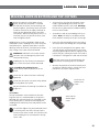
USER MANUAL
User manual in original format.
Article no: 0458-395-0802
LOGOSOL PH360
Read through the user manual carefully and make sure you understand its contents
before you use the planer/moulder.
This user manual contains important safety instructions
Warning! Incorrect use can result in serious personal injury or even death to the
operator or others.
Thank you for choosing
a Logosol machine!
Welcome! We are very pleased that you have
demonstrated your confidence in us by purchasing
this planer/moulder and we will do our utmost to meet
your expectations.
Logosol has been manufacturing sawmills since 1988,
and since then we have supplied machines to satisfied
customers worldwide. We are want to assist you in
safely achieving the very best possible results from your
planer/molder. We therefore recommend that you take
the time to read this user manual from cover to cover
before you begin using the machine.
Remember that the planer/moulder itself is just part of
the value of the product. Much of the value is also to
be found in the expertise we pass on to you in the user
manuals. It would be a pity if that were not utilized.
We hope you get a lot of satisfaction from the use of
your planer/moulder.
Bengt-Olov Byström
Founder and Chairman of the Board,
Logosol AB
LOGOSOL is engaged in continuous development of its products.
We must therefore reserve the right to change
the design and form of our products.
Text: Bo Mårtensson
Document: Logosol PH360 Manual
Image: Bo Mårtensson, Lars Wahlström
Last Revised: September 2014
Manual, product no. 0458-395-0802
© 2010 LOGOSOL, Härnösand Sweden
2
LOGOSOL PH360
Table of contents
Safety instructions
4
Tools required
6
Machine description
7
Preparations
7
Setup
8
Chip management
8
In and outfeed table
9
Starting the sawmill
9
Control panel
10
Bottom cutter
11
Top cutter
13
Molding knife in bottom and top
cutter
15
Side cutters
16
Instruction variable
20
Maintenance
21
Setting the upper chassis' plan
22
Molding tips
22
Starter package PH360: molding
knives & examples of combinations
23
Electrical schematic
26
Technical data
29
List of components
30
Overview
32
EC Declaration
43
3
Safety instructions
•
•
Make sure that all warning and information
stickers are in place, and that they are clean and
legible. Any damaged stickers must be replaced
immediately.
Persons who do not have the necessary knowledge or experience of planers must not use
this planer/moulder. This instructions do not
constitute training in machine planing. Contact
Logosol for information regarding training in
machine planing.
•
Ensure that non-authorized persons do not use
this moulder.
•
All protection must be assembled before the
molder is used.
•
Always use protective goggles and ear protection.
•
•
Never use the molder if you are under the influence of strong medication, alcohol or any other
strong drugs.
Always check that knobs, screws, nuts, fences,
sleeves, planing cutters, planing knives, etc. are
properly tightened. Also check that the cutter
can rotate freely and that there are no tools in
or on the planer/moulder before it is started.
•
Never use the planer/moulder in poor visual
conditions such as bad lighting.
•
Never place tools or hands into the in or outfeed
areas when the planer/moulder is running.
•
Never intervene in the planer/moulder before
you have ensured that the power is switched
off and the planer/moulder cannot be started
accidentally.
Planing/moulding
4
•
Always measure the workpiece and set suitable
thickness and width before planing.
•
There is a high risk of accident if you feed in a
workpiece that is not high enough for the feed
rollers to get hold of the workpiece.
•
•
Small dimensions must be planed using fixtures,
e.g. a piece of wood with a customized groove
that extends along the full length of the table.
Never stand along the the workpiece's extension
line as kickback can occur, and bits of the workpiece can be thrown out of the planer/moulder.
This applies to both the in and outfeed sides,
although the risk is greater on the infeed side.
Key to symbols
For your own safety, read the entire instruction manual carefully and do not start the
planer/moulder before you have understood
everything.
Use approved ear protection and protective
goggles. Hearing can be damaged after only
a short exposure
Sharp rotating tools. Be careful not to let
your fingers get near the cutter.
This symbol means "WARNING!". Be extra
vigilant when this symbol appears in the
manual text.
This symbol is followed by a prompt. Be
extra vigilant when this symbol appears in
the manual text.
LOGOSOL PH360
General
•
•
•
Check the molder/planer as soon as you receive
it. Report any transport damage to the transport
company immediately.
LIFT THE PLANER/MOULDER using a fork-lift or
pallet jack.
When replacing spare parts, use only original
parts and note that anything electrical must be
assembled by a qualified electrician.
Applications
The planer/moulder can be used for planing/molding
and planing wood, chipboard, board, etc.
Hard materials such as chipboard, teak, MDF, etc.
require hard carbide tools, see the Logosol-Toolbox
catalogue.
The planer/moulder is designed for indoor use, with
temporary outdoor use.
Environmental requirements
The temperature in the premises should be above
freezing, unless special measures are taken.
Safety distance
Other than the operator, no-one should
be within 3 meters (10 foot) of the planer/
moulder's sides or 8 meters (26 foot) from
the in and outfeed sides during operation.
Mark a limit that prevents anyone accidentally wandering into the risk area.
Demarcation
PH360 with in and
outfeed table
3 m (10 ft)
Risk area
Max 8 m (26 ft)
6 m (20 ft)
The operator's work area
The barrier behind
the infeed side
3m
(10 ft)
Tips: An extended infeed table is practical to use,
and prevents anyone coming into the risk area.
Ventilation in the premises must be mechanical, and
of a good standard.
The planer/moulder must be connected to a chip
extractor, which is approved according to CE-standards, see page 10.
5
tools required
A list of the tools required to be able
to work with the planer/moulder:
The following spacer ringers are
supplied:
Allen key 4 mm (supplied)
Allen key 5 mm
Allen key 6 mm
Open ended wrench 10 mm (supplied)
Wrench 10 mm
Ring wrench 13 mm
Open ended wrench 30 mm (supplied)
(for milling spindle)
Adjustable wrench 8" or 10"
(for milling spindle)
Sliding caliper
Measuring tape or ruler
Paraffin oil for the table
Whetstone
3 x 40 mm height
2 x 20 mm height
2 x 10 mm height
1 x 5 mm height
2 x 2 mm height
1 x 1 mm height
1 x 0.5 mm height
1 x 0.3 mm height
1 x 0.2 mm height
1 x 0.1 mm height per cutter
These spacer rings allow you to set the required height.
Tips! Make a tool board with the tools you
need, and position it next to the planer/moulder
so that you can see it easily. Look at the tool
board before you start the planer/moulder to
see if any tools are missing. They could have
been left in the planer/moulder!
Machine description
The PH360 is a planer/moulder that can work four
sides of a workpiece in one action. The planer/moulder is contained in a stable and strong chassis. The
planer/moulder table and slide for the moving cutter
are made of planed cast iron.
The workpiece is fed, lying on the planer table,
through the planer by four feed rollers as well as
an outfeed roller. The rollers are driven by a chain
transmission with separate motor. The workpiece is
controlled laterally with adjustable fences and pressure rollers.
The work is done using a top cutter and a bottom
cutter, that are hung at both ends, as well as two
side cutters which are fixed to the planer table. All
the cutters are driven by separate motors, via a belt
transmission.
6
The cutters and feed rollers are covered by a foldable protective cover plate with window. The cover
plate is supplied with a safety switch. Another safety
switch sits behind the top edge of the cover plate on
the infeed side. A 100 mm (4”) hose is connected
to the bottom and side cutters and a 125 mm (5”)
hose is connected to the top cutter with the option
of an additional 100 mm (4”) for connection to the
chip extractor.
Table surface
The table is cast in the highest quality. The table surface is specially processed for the highest precision
and the best anti-friction qualities. When the planer/
moulder is new, it requires a driving-in period until
the table gets a slightly shinier surface to optimize
the anti-friction qualities. During this period, we
recommend that you use a lubricant or wax on the
table.
LOGOSOL PH360
preparations
Certain parts are not assembled on delivery for
transport and packaging reasons.
Figure 1.
1. Assemble the control panel in place with the
arm where the cabling goes, (232), (251).
2. Assemble all safety doors.
3. Assemble the infeed table (212). [Figure 1]
• Screw down all adjustable screws (B) in the
bottom.
• Insert all screws (A) tighten by hand.
• Insert the adjustment screws (C) and adjust
the table so it is straight.
• Adjust exactly: The highest position of the infeed table must be on the same level as the
cast machine table. Check with a long, straight
fence rail.
• Adjust the height of the table so that it
touches the cast iron table with the adjustment
screws (B) and tighten the holding screws (A).
• Check the table angle and table height and
insert the table fixture’s bottom lock screws (D)
which are fastened using nuts on the inside of
the chassis.
4. Assemble the outfeed table (253). [Figure 2]
5. Assemble the side fences [Figure 3]
6. Connect the planer/moulder to the chip extractor.
7. Before the planer/moulder is connected to the
electrical circuit, check that all cutters can rotate
freely, and that all parts are fixed.
Hole pattern key:
A: Holding screws for the infeed table.
B: Holes for accessing the adjusting screws where the screw
head lies under the table fixture.
C: Threaded hole for adjustment screws for setting the table angle.
D: Hole for lock screws.
E: Fixing point for adjustable side fence. A double hole pattern
39
means
that the fence can be placed in an outer or inner position
41
25
24
27
26
42
16
16
16
42
16
14
15
Figure 3.
22
38
41
22
22
1
Insex M10 15mm
3
Bricka 10,8x22x2
41
1
40
1
39
1
38
1
Tap-GN30078-M10x20-Wiberger 14
Passkruv ISO7379 d12 L45 M10
17
Distans 15
bussning
Automatstål
27
1
Passkruv ISO7379 d12 L20 M10
26
1
Insex M10 40mm
25
1
Passkruv ISO7379 d12 L25 M10
24
1
Annhåll låsplåt
23
1
Annhåll låsplåt Distans bussning
22
3
Fästbusning annhåll
Oljebrons
19
1
Annhåll profil 3
AL
17
2
Mutter M12
16
5
1
Annhåll justerspak
Stål Blankförzinkad
22
Bricka 11x22x3
15
14
2
Länkarm inmatning
Automatstål
Plattstång 25x25 L80
13
13
2
Fäste länkarm
Automatstål
Stång D30 L36
360-124-3
Nr.
Antal
Dimension
Anmärkning
42
43
Konstr.
_
M10
Ritad
MK
M10-30mm
24
Stål 16
Blankförzinkad
Bricka 13x24x2
Benämning
Kop.
_
Kontr.
_
Stand.
_
16
42
Stång D30 L11
360-342
1312
Plåt 4mm
360-167-2
Automatstål
Stång D30 L25
360-134-1
Lager d12 D18 L25
AL-profil:360-325
40x30x800
360-125-1
Material
Godk.
_
39
Bricka 11x22x3
Lever-GN300-S78-Wiberger
16
MOReTENs
M10-25mm
27
26
42
42
13
M10-25mm
25
43
23
Figure 2.
PH360
19
14
17
Skala
1:20
Matarbord Ass
16
22
38
360-329
22
23
360-142-3
43
1
42
3
Bricka 10,8x22x2
41
1
Lever-GN300-S78-Wiberger
Insex M10 15mm
40
1
Tap-GN30078-M10x20-Wiberger
Passkruv ISO7379 d12 L45 M10
Ersatt av
39
1
_
38
1
Distans bussning
Blad.
Dat.
27
1
Passkruv ISO7379 d12 L20 M10
26
1
Insex M10 40mm
25
1
Passkruv ISO7379 d12 L25 M10
24
1
Annhåll låsplåt
23
1
Annhåll låsplåt Distans bussning
Automa
22
3
Fästbusning annhåll
Oljebr
19
1
Annhåll profil 3
17
2
Mutter M12
16
5
15
1
Annhåll justerspak
14
2
Länkarm inmatning
13
2
Fäste länkarm
Nr.
Antal
Benämning
_
1 av 1
2010-11-15
360-277
43
Konstr.
_
Ritad
MK
Automa
131
AL
Bricka 13x24x2
Kop.
_
Kontr.
_
MOReTENs
M10-25mm
Stål Blankf
Ersätter
Ritn.-nr
42
19
14
Stål Blankf
Automa
Automa
Stand.
_
Mate
Godk.
_
Matarbord
M10-25mm
M10
M10-30mm
7
setup
Check your PH360 as soon as you receive it. Any
transport damage must be reported to the transport
company immediately.
Most of the planer/moulder is protected against rust,
but it will require extra maintenance in the form of
lubrication for all the parts not protected against
rust. See the Maintenance section.
•
•
•
Place the planer on a stable and flat base. Preferably screw the planer down using the holes in
the base, if the castor set is not used.
Ensure that there is enough space for the
longest boards you want to plane at the in and
outfeed sides, and that there is enough space
for maintenance and timber stocks.
Connect the chip hoses and fix using the hose
clips on the planer and fan.
•
Hang the planer's electrical cable on the ceiling
or protect it in another way. Never step on the
cable. The planer/moulder should be connected
via an earth-fault protection switch.
•
Ensure that lighting is good. There should also
be good general lighting. Also set up a strong
lamp directly over the planer. Ensure that there
is no risk of glare.
Space requirements
The planer/moulder needs a space of at least 2 m
(6 1/2 ft) wide. The length required depends on the
length of the workpieces you want to plane. The
minimum length is 4 m (13 ft).
Anchoring
For the highest safety, the planer/moulder must be
anchored to the floor using screws. Screw diameter
8-10 mm (3/10"- 4/10").
chip management
The PH360 must be connected to a chip fan with a
capacity of at least 3,000 m3/h (10,000 cubic feet/
hr) . Logosol has a range of pipes, sleeves and hoses.
Ask our advice.
Remember that you need an air vent in your chip
container (e.g. a fine net or filter if you carry out
chip collection indoors). Poor suction is often due to
poor airflow from the chip container. If you work in
heated premises, remember that the fan will quickly
cool the space if you do not lead the filtered air back
into the building. Consideration must be taken for
fire risk and dust emissions (discharge) in connection
with chip collection.
Technical requirements chip
extractor
•
The chip extractor must be approved according
to the CE-standard.
•
The airflow "without external connection" must
be approx. 4000-5000 m3/hour (13,000-16,500
cubic feet/hour).
•
(The manufacturer's standard indication of
airflow.)
Fire risk and dust emission in connection with
chip management.
•
The sleeve diameters for the planer = 100 mm
(4”) x 4 and 125 mm (5") x 1.
Contact the local authorities for advice in designing a chip collection system to conform
with rules in your area.
•
The pressure loss in the planer is 26 mm of
water column at 25 m/s (1 inch of water column
at 82 ft/s) .
Position the chip fan so that you can easily
reach the switch.
8
Chips that are left in the planer/moulder must
be vacuumed up after every work session.
LOGOSOL PH360
In and outfeed table
Note that the outfeed table can easily be folded up
so you can move around the planer.
The tables must mainly be completely in line with
one another (when the cut in the bottom cutter is 0
mm (0") but in certain cases it can be an advantage
for the ends of the feed table to lie slightly higher
(1-5 mm) than the planer table to reduce in and
outfeed marks (snipe). This particularly applies when
thin or soft workpieces are being processed. The
outer edges must then always lie slightly higher than
the planer table.
It is extremely important that the infeed table, planer
table and outfeed table are correctly setup so that
there are no cutter marks on the ends of the object.
Starting the planer
Risk of serious damage.
Before starting:
• Ensure that all cutters can rotate freely.
Check that no tools have been left in the
planer.
•
Ensure that the emergency stop (a11) is pulled
out.
Check that all screws have been sufficiently
tightened.
•
Ensure that the top door is closed, and impacts
the door switch (179).
Check that the cutters can rotate freely before
the safety doors are closed.
•
Check that no-one other than the operator is
inside the safety distance.
Do you remember the warning instructions on
pages 4-5?
Connect the planer electrically. Watch the
rotational direction. If you are standing by the
feeder gears, the rotational direction of the
top cutter must be counter-clockwise.
9
Control panel
CONTROL PANEL
The top red button (a11) is the emergency stop and
switches off the power to all functions. When the
emergency stop is used, it must be pulled out again
in order for the planer/moulder to be re-started.
Under the emergency stop is a light (a10) which
indicates that the power supply is connected. When
replacing knives and during servicing, for example,
the power switch (a9) must be in the off position.
Check that the light (a10) is not lit.
The bottom black row of buttons (a8) start the
planer's motors. The top red row of buttons (a7)
stops the planer's motors (a7). Above each button
there is a light (a6) which indicates that the relevant
motor is running.
10
The button's function is from the right:
1. Starting the planer cutter (lower horizontal cutter)
2. Starting the side cutter, right
3. Starting the side cutter, left
4. Starting the planer cutter (upper horizontal cutter)
5. Starting the feed
6. To control extra motors, or a fifth cutter
LOGOSOL PH360
bottom cutter
Grinding the planing knife
Before you open the safety doors on the
planer, ensure that the power is switched
off and that the cutters are not rotating. Use
protective gloves, particularly when you need
to loosen screws that are tightly fastened, or
when you are tightening screws (see warning
instructions). Beware of the planer knives. It is
extremely easy to cut yourself on these, even
with the slightest touch.
Always grind the knives in pairs, so they are the
same height, min. 15 mm (.600"), otherwise vibrations could occur in the cutter. The grinding angle
must be 38 degrees. You can order a grinder from
Logosol for sharpening molding and planing knives
(Tormek Grinder, item no. 7010-000-1000, Jig for
planing knives, item no. 7010-000-1005).
Adjusting the bottom cutter's
planing knife
The bottom cutter is fixed to the planer table on the
planer's infeed side. Two planer knives are mounted in two of the bottom cutter's tooling slots on
delivery (planer knife 410 mm (16") HSS, item no.
7000-002-8410). Another two planer knives, or
molding knives can be mounted in the two empty
tooling slots.
The bottom cutter's planing knife must be set so
that it is on the same level as and in line with the
planer table.
• Loosen the chip breaker's lock screws (B) that
are found in the groove between the chip breaker (A) and the cutter using a 10 mm (4/10")
key (supplied). After this the knife can be raised
or lowered using the two adjustable screws
(4 mm socket head) (C) that are recessed by
the cutter's keyway. Use a 4 mm socket head
screw (supplied). The knife must stick out 1 mm
(.040") from the cutter body to align with the
molding knife from Logosol.
Setting the bottom cutter's cut
The cut of the bottom cutter is set using a lever
(211). Locking is done using a lever (224).
The normal cut on the bottom cutter is 2 mm
(8/100").
Disassembling the planer knife
•
The planing knife is disassembled by loosening the
chip breaker's (A) lock screws (B) and then unscrewing the planing knife with adjuster screws (C).
A
Check the level of the knife by placing a bit of
planed edging on the planer table behind the
cutter. The cutter's knife should then touch the
edging (see image below). Another method is to
B
F
D
E
C
11
use a magnetic knife setter (magnetic adjuster,
lower cutter, item no. 7500-001-0051): Loosen
the chip breaker's lock screws and tighten the
knife's adjustable screws several turns. Rotate
the cutter so that the planing knife is in its uppermost position. Place the magnetic adjuster
straight and in a V-shape on the planer table behind the cutter so that the knife edge is directly
under the magnetic adjuster's magnets. Set up
the adjustable screws until you feel that the
knife is lifted by the magnet, so that it reaches
the correct level. Tighten the lock screws and
then carefully screw the adjustable screws so
that they fix the knife in this position.
•
Tighten the screws locking the knife in position
counter-clockwise (i.e. out of the keyway). Start
by tightening carefully. Move from the sides and
in towards the middle, retightening them later.
•
Carefully screw the adjustable screws in the
bottom of the knife's recess. If you tighten these
too hard, the knife will crack.
After adjusting or replacing planing knives:
Check that no tools have been left in the
planer.
Check that all screws have been sufficiently
tightened.
Check that the cutters can rotate freely before
the safety doors are closed.
Do you remember the warning instructions on
pages 4-5?
12
LOGOSOL PH360
top cutter
Before you open the safety doors on the
planer, ensure that the power is switched
off and that the cutters are not rotating. Use
protective gloves, particularly when you need
to loosen screws that are tightly fastened, or
when you are tightening screws (see safety
instructions). Beware of the planer knives. It is
extremely easy to cut yourself on these, even
with the slightest touch.
Setting the cut of the top cutter
The planer thickness is set using the planing table
crank (189). The set thickness can be read on the
indicator (109) on the machine stand. The indicator
can be calibrated. Plane some wood and adjust the
top cutter until you get the correct height. Release
the green cover (168). The ring above the indicator
has a stop screw. Turn the ring so that it shows the
planing height that has been planed.
The top cutter is fixed to the chassis and hung at
both ends. Two planing knives are mounted in two of
the bottom cutter's tooling slots on delivery (planer
knife 510 mm (20") HSS, item no. 7000-002-8510).
Another two planing knives, or molding knives can be
mounted in the two empty tooling slots.
Always set the top cutter uppermost to reduce any
slack in the threads. If the top cutter needs to be
lowered, lower it half a rotation too low and then
raise it into the correct position. Once you have the
top cutter set at the correct height, you can lock it
in position with the handle to the right of the feed
motor assembly.
Disassembling, assembling and
grinding planing knives
See above, under the Bottom cutter section. Exceptions:
The minimum height of the planing knifes are different.
Make sure you´re using the right Setting Block.
After adjusting or replacing planing knives:
Check that no tools have been left in
the planer.
Check that all screws have been sufficiently
tightened.
Check that the cutters can rotate freely before
the safety doors are closed.
Do you remember the warning instructions on
pages 4-5?
Adjusting planing knives
Adjust the planing knives so that they are the same
level and protrude 1 mm (.040"). This is done using
an aluminum adjustment block (item no. 7500-0001020), found in the component packaging on the
planer table when the planer/moulder is delivered.
Loosen the chip breaker's lock screws slightly, and
place the adjustment block over the knife. Adjust
the knife up or down until the knife brushes against
the block when it passes above the knife. (The planing knife protrusion can also be adjusted using a
magnetic adjuster for the top cutter, item no. 7500001-0050. See the instructions enclosed with the
magnetic adjuster.)
Tighten the lock screws that lock the knife,
counter-clockwise. Start by tightening carefully. Move from the sides in move towards the
middle, retightening them later.
13
When the top cutter's bearing housing is
adjusted, or when the planing knife's cut is
changed, the counter's pre-set must be height
calibrated.
Adjustment of the trapezoidal
threaded bar's chain transmission
The chain, which raises and lowers the table, must
not be slack, but needs to be tensioned enough that
teeth bite correctly. The tension is set using a nut
that is located in the chassis under the planer table
on the outfeed side.
Do not touch the chain tension as long as the
raising and lowering of the table works, as an
incorrect tension could mean that the chain
disengages.
14
LOGOSOL PH360
molding knife in bottom and top cutters
Before you open the safety doors on the
planer, ensure that the power is switched
off and that the cutters are not rotating. Use
protective gloves, particularly when you need
to loosen screws that are tightly fastened, or
when you are tightening screws (see safety
instructions). Beware of the planer knives. It is
extremely easy to cut yourself on these, even
with the slightest touch.
•
To insert knives into the top or bottom cutter
heads, a gib/moulding knife clamp must be
used to hold the knife in the head. Warning:
Do not use any other device to hold moulding
knives in these heads!
•
Assemble the Gib (D) and molding knife (E) as
shown. Note: The holes in the bottom of the
knife should fit securely on the pins on the gib.
Molding knives can be assembled in both the top
and bottom cutters. Molding knives must always be
mounted in pairs – opposite each other. A certain
sideways offset of the knife, can however be accepted, as long as the cutter remains balanced.
•
Lower the gib and molding knife to the side of
the cutter where the tooling slots are extended.
•
Insert the knife and gib into the groove. Measure the position using the groove in the cutter,
and fix by tightening the screw (F) tightly on the
back of the gib. (Turning the screw in the Gib as
if to loosen it will tighten the Gib into the head.)
Warning! Unbalance in the cutter creates
vibrations that can damage the planer and
cause personal injury.
The lock screw must not be placed over the
area where the tooling slots are extended.
Molding knives must always be mounted in
pairs, so that the cutter remains balanced.
•
After assembling the planing knives:
Check that no tools have been left in the
planer.
Measure the position of the knife laterally and
assemble an identical knife in exactly the same
position on the cutter's opposite side.
Check that all screws have been sufficiently
tightened.
Check that the cutters can rotate freely before
the safety doors are closed.
Knife Gibs for
PH360 lower
cutter.
Do you remember the warning instructions on
pages 4-5?
Assembly
The top and bottom cutter heads have four tooling slots each. As mentioned above, the planer is
delivered with two planing knives assembled in two
of the tooling slots. In the other two tooling slots,
molding knives of different sizes and profiles can be
assembled.
Knife Gibs for
PH360 upper
cutter.
On the front edge of the planer/moulder, there
is a limiting cover that limits the top cutter's
maximum cut when turned. This must be used
when molding knives are mounted in the top
cutter (196).
15
SIDE CUTTERS
D
A
6
8
7
C
B
F
E
Before you open the safety doors on the
planer, ensure that the power is switched
off and that the cutters are not rotating. Use
protective gloves, particularly when you need
to loosen screws that are tightly fastened, or
when you are tightening screws (see warning
instructions).
The side cutters are fixed to the planer table. The
spindles are 30 mm (1 2/10") in diameter, which is
a standard measurement. Upon delivery, the planer
is equipped with two universal cutters with planing
knives, which you can easily replace with molding
knives. For reasons of safety, the cutters work with
conventional milling (the workpiece is fed towards
the molder's cutting motion). This means that the
lock nut and spindle on the moving side cutter must
be left-hand threaded.
The moveable side cutter's lock nut is lefthand threaded.
After assembling the molding knives:
Check that no tools have been left in the planer.
Check that all screws have been sufficiently
tightened.
16
Check that the cutters can rotate freely before
the safety doors are closed.
Do you remember the warning instructions on
pages 4–5?
Disassembling
Cutter 2 (Right, fixed cutters): Loosen the nut on
the spindle with a 30 mm wrench (supplied) and
a 1/2” or 13 mm wrench or adjustable wrench.
Unscrew the nut and remove the cutter (A) and any
spacing rings under the cutter.
Cutter 3 (left, moveable cutters): Crank the cutters to their previous position. The nut is loosened
in the same way as for cutter 2, with the difference
that the nut for cutter 3 is left-hand threaded and is
therefore screwed in the opposite direction.
Tip: The side cutter nuts are loosened by turning them
in the same direction as their respective cutter rotates.
Replacing knives
Loosen the lock screw (B) with a 4 mm Allen wrench
(C) (supplied) and remove the chip breaker (D). Then
remove the knife (E) from the peg (F). Insert a new
wrench and tighten the locking screw tightly.
LOGOSOL PH360
Ensure that you turn the knives in the right
direction (see page 16) when you assemble
them in the cutter. The cutting edge must be
turned towards the chip breaker. Also check
that the cutter is facing the right direction on
the spindle. All of the planer/moulder's cutters
turn the same way as with conventional milling.
Check that the non-corrosive spring plate in
front of the moveable cutter is not at risk of being bent towards the cutter by the workpiece's
unplaned edge. Pay particular attention when
cutting workpieces of different widths.
Ensure that the cutter can rotate freely and that
the plate working as a chip barrier behind the
moveable cutter is at a distance of approx. 5 mm
from the cutter's largest cutting diameter.
Height setting
The side cutter's height is set by adding or removing the spacers that are supplied in the component
package on delivery.
Spacer height:
Spacers 40 mm Spacers 20 mm Spacers 10 mm Spacers 5 mm Schim set (0.1 – 2.0 mm)
item no. 7502-001-0038
item no. 7502-001-0042
item no. 7502-001-0044
item no. 7502-001-0046
item no. 7502-001-0230
To remove the planing knife from the side cutters,
loosen the knife's lock screws that are recessed into
the cutters. Use a 4 mm Allen Wrench (supplied).
The height settings for tongue and grooves:
When tongues and grooves need to be moulded, it is
important that these are made opposite one another,
i.e. at the same height above the planing table.
• Remove the cutter from the spindle (see above
under the Disassembling heading).
• Decide how you want the board to look. E.g. 8
mm above the groove, 6 mm groove and 7 mm
under the groove (see image to the left).
• Assemble the molding knife and screw the
socket head screws that hold the knife properly.
• Place the cutter on the spindle completely without spacers. Measure the distance from the top
edge of the knife down to the planer table.
cutter is pre-set, the height of the knife above the
table must be 30 mm (7 + 6 + 17 = 30 mm). If, for
example, the height of the knife above the table is
measured to 15.2 mm, the cutter must be raised
14.8 mm (0.58") (15.2 + 14.8 = 30 mm).
Take the following measures:
• Remove the cutter.
• Combine spacers to the calculated thickness
(14.8 mm (0.58") in this example) and thread
them onto the spindle.
• Place the cutter on the spindle, screw on the
lock nut and tighten properly. Check that the
cutter can rotate freely.
• Carry out the points above on the cutter with
the tongue knife, so that it is placed at the same
height above the table.
• Test-plane a small board, and check that the
tongue and groove are at the right height in
relation to one another.
Alternatively, the knife can be set arbitrarily, after
which a test bit is run. Measure the test bit and correct the knife height.
Spacers must also be placed above the cutter
so that it is fixed on the spindle. Add some of
the distance rings that are not used for height
setting, so that the thickest ring lies highest and
protrudes several millimeters above the lowest
threads on the threaded bar. Then screw the
nuts on the threaded bar and tighten properly.
Grinding
To recover the sharpness of the knife, you can grind
the flat side of the knife. Thus retaining the same
profile for the pair of knives. Always grind the knives
in pairs, so that they have the same weight, otherwise vibrations could occur in the cutter. You can
order a grinder from Logosol for sharpening planing
and molding knives (Tormek Grinder, item no. 7010000-1000, Jig for planing knives, item no. 7010000-1012).
If the profile of the knife is damaged, this should be
re-ground by a professional knife sharpener. This is
a service that is normally available locally, otherwise
contact Logosol.
If the cutter is 40 mm and the groove (6 mm in this
example) is in the middle of the knife, the height
of the knife above the groove is 17 mm. When the
17
Adjusting the fence by cutter 2
In general
The front side fence has a double set of holes for
assembly. It can therefore be assembled in two
basic positions. When the TB90 system is used, the
fence will be fitted in the pair of holes on the right,
as seen from the infeed side (see assembly of side
fence, page 7). When cutters with larger diameters
are used, the fence can be moved to the left pair of
holes, so that the stroke length is sufficient.
The fixed cutter has two fences, the front (62) and
the back fence (54). The front fence controls how
much the cutter cuts, and the back fence works as a
support for the workpiece when it has passed cutter
2 and is ready to be worked by cutter 3.
Both fences must be in line with one another, but
offset in parallel so that the front fence is slightly
more to the right (see fig.). In this way, the back
fence will support the workpiece once it has been
cut by cutter 2 (the workpiece is slightly smaller then).
The fence is fixed by socket head screws in the fence
holders (55) according to fig. The screws that lock the
fence in the horizontal direction are 13 mm (5/10")
hexagonal screws and sit in the fence's U profile. In
addition, there are micro adjustments on the fence.
When the hexagonal screws are loosened slightly,
the knob for micro-adjustments can be turned. If the
angle of the fence needs to be adjusted, both the
hexagonal and socket head screws must be loosened.
•
•
•
•
The plane diameter that is inline with the back
fence is where you need to measure to, the
cutter’s plane diameter that is higher than 30
mm above the table height is unimportant here.
Align the back fence along the guard rail, which
is still tight against the first fence and tighten it.
The cut is now 0 mm. The first fence, cutter and
back fence are fully inline, and the first fence
controls the angle through the machine.
Remove the fence rail and all loose tools from
the machine.
Move the first fence back to the required cut
and lock it using the tie-back knob. (Around 2
mm is usually a suitable cut for the first cutter.)
Method 2:
• The back fence is pulled in so that it is not used,
and is fixed there. (Check that the cutter can
rotate freely.)
• Position the front fence so that the required cut
depth is obtained and the fence stands straight.
Tighten the screws that fix the fence.
• Close the safety doors and take the measures
required to start the planer/moulder (see page 4).
• Start the bottom cutter, both side cutters and
the feeder and feed in a test piece of approx. 1
meter (3 ft). Stop the planer/moulder just as the
board reaches the moveable cutter (cutter 3).
• Drive the back fence towards the planed part of
the board.
INSTALLATION OF SIDE FENCES
Method 1:
• Insert the first fence inwards, for minimal cutting. Add a straight aluminum fence rail tight
against the fence. Adjust the fence using the lever until the loose fence rail touches the cutter’s
plane diameter (the outer rotating line) as it lies
against the first fence.
18
Installation jig for adjusting fences.
LOGOSOL PH360
•
Check that the test piece is lying against both
fences and tighten the back fence's lock screws.
Check that all screws that fix the fences are
properly tightened, and that the cutter can
rotate freely.
Tip: If there is a problem in that the board does not
follow the fences, it could be that the back fence
is not at the right level in relation to the cutter,
that the fences are not completely parallel to one
another, or that the fence does not run straight
through the planer/moulder. If it is difficult to get
the fence to lie perfectly straight through the planer/
moulder, it is better that the fences are slightly
angled to the left, towards cutter 3, as the feed rollers will then press the workpiece against the fence.
If the fences lie at a slight angle to the right, away
from cutter 3, the feed rollers will pull the object
away from the fence, which will lead to incorrect
measurements and a badly planed surface.
Adjusting the moveable cutter
(cutter 3)
Loosen the lock handle (91) that is located on the
slide under the table and/or the slotted screw that
is located above the slide (38). Then insert the crank
(260) onto the threaded rod on the side of the planer and move the side cutter head to the required
planing width. One rotation of the crank is 4 mm.
Measure the distance between the cutter knives and
the back fence with sliding caliper. This measurement becomes the width of the finished board. Fix
this position with the lock handle under the table.
Indicator
The indicator shows the width measurement in mm
in black, and 1/10 mm in red. Each time, when setting to a new profile: plane a board, measure the
outer measurements with the sliding caliper. Turn
the small handle to the right of the indicator so this
measurement is shown in the window.
Installing a pressure roller for moveable cutters
Two pressure rollers are located in front of the
moveable cutter, to press the workpiece towards
the fence. By adjusting this you can also decide how
wide the workpieces fed into the planer/moulder
can be. These pressure rollers sit on an arm (77) that
is anchored in the moveable cutter's slide, which
means that they move with the cutter when this is
adjusted.
To set the pressure rollers, loosen the socket head
screws that fix the arm in the moveable cutter's
slide with a 6 mm Allen wrench. Adjust the arm so
that the press rollers are pressed in by approx. 5 mm
when the workpiece is fed into the planer.
A spring plate (supplied on delivery) can be mounted
in front of the moveable cutter between the press
rollers' arm and screw plate. The spring plate has
oval holes that allow adjustment in and out from
the workpiece. The spring plate works partly as a
tension control, but also as a fence in front of the
cutter which reduces the risk of long splinters being
knocked out of the workpiece during large cuts.
Adjust the feather plate so that it is pushed in to a
couple of millimeters from the unplaned edge of the
workpiece.
Check that there is no risk of the spring plate
pushing into the cutter's knife if you are planing an object of variable width. Maintain a
safety margin of at least one centimeter in the
pressed in position.
After the moveable cutter, there is another pressure
roller (76) which pushes the cut workpiece towards
the back fence. Set the pressure roller so that it
protrudes approx. 1-3 mm from the cutter's smallest
plane diameter, at the same height as the pressure
roller.
The height of the pressure roller can also be set with
washers above or below it. Which may be required
for producing certain profiles.
Test run
Always run a test piece and make subsequent adjustments. Run a piece straight through the planer
at the slowest feed speed. Look through the cover
while it is being planed and check that the board is
lying against the fences in front of and behind cutter
2.
Then measure the profile, its height and width, and
subsequently adjust the cutters and the setting for
the molding knives if required.
19
variable feed motor instruction
Warning! Do not turn the adjustment knob when
the planer/moulder is not running.
AGIP
BLASIA 32
Assembly (if the variable feed motor
is assembled in place).
SHELL
A.T.F DEXRON
Assemble the feed motor package on the last feed
roller. Make sure that the torque stay is in place.
Lock this with the central screw on the roller.
ESSO
A.T.F DEXRON
MOBIL
A.T.F 220
Setting the feed speed
CASTROL
DEXTRON II
BP
AUTRAN DX
Turn the wheel clockwise to increase the speed.
Indicator dial for the feed speed
The indicator dial is/must be mounted in the hub
of the wheel. It works like an indicator that has a
weight in one part, so the indicator moves. The
black indicator shows a figure.
The indicator dial has a relative scale. See the numbers as an indicator. The higher the number, the
greater the speed.
Start the planer/moulder and turn the wheel so the
planer reaches minimum speed.
Remove the indicator dial and turn it so the indicator
is set to zero. Then press the indicator dial in with
the indicator pointing upwards towards zero.
Use the indicator dial so that you can return to the
best speed for the profile you are planing.
If you have a 3-15 m/min (10-49 ft/min) gear:
0 on the indicator dial is 3 m/min (10 ft/min)
8 on the indicator dial is 15 m/min (49 ft/min)
If you have a 6-30 m/min (19 1/2-98 ft/min)
gear:
0 on the indicator dial is 6 m/min (19 1/2 ft/min)
8 on the indicator dial is 30 m/min (98 ft/min)
20
Maintenance
Fluid should be visible in the fluid level glass. The
level is checked when the planetary gear is not
running.
Top up if no fluid is visible in the glass. Use oil for
automatic gearboxes according to the table below,
or use compatible oil.
The variator is filled with AGIP BLASIA 32 at the
factory and does not normally require an oil change
during its life.
The worm gear oil does not normally need changing
or topping up during the life of the gear.
LOGOSOL PH360
MAINTENANCE
The PH360 is easy to maintain as 95% of the planer/
moulder is protected against rust. The maintenance
required, is mentioned below. Ensure that the power
to the planer/moulder is switched off before beginning maintenance.
After each work session:
• Clean chips from the planer/moulder. Also remove any chips from under the planer/moulder.
•
Clean any resin off the table. Use mineral spirit
if necessary. Lubricate the table with paraffin oil,
for example.
USING OR STORING IN COLD OR DAMP
ENVIRONMENTS
If the planer will be stored in a cold or damp environment over a longer period, all corrosive parts
must be treated with a rust inhibitor. Cover the
planer.
Water can condense in closed spaces. Check that
the motors are dry inside by loosening the draining
plugs. Check the control panel box.
Maintain at regular intervals as
follows
Lubricate these areas regularly:
• Feed roller Bushings.
• Sprockets, including top and bottom layers.
• The chain for setting table height.
• The chain driving the feed rollers.
• The two bars that the moveable slide runs on, as
well as the slide's trapezoidal thread.
• Cast iron table.
Check that all screws and bolt connections are tightened and that cables and electrical connectors are
in good condition.
21
setting the upper chassis' plan
Foundations
Re-setting the chassis plan requires a serious intervention in the planer. Ensure that this is necessary.
The planer is set correctly when leaving the factory,
but may have adjusted
due to careless transport or serious impact.
Setting cutters
1. Loosen the screws to the bearing bracket (4 x
M8 on each side)
2. Add a completely level block on the table, directly under the cutter.
3. Turn the crank so the cutter is lifted slightly
(make sure the knife does not bite)
4. Lock the screws to the bearing bracket
Setting only the planing table if, for example,
the chain has come loose, or the cutters do not
have enough trimming allowance.
4. Lift up each threaded sprocket so the cutter is at
a tangent to the block along its entire length.
5. Check the measurement of the front and back
of the table to the stand, adjust the front or
back pair of sprockets
6. Assemble on the chain to the planing table.
7. Before assembly you must check that each
threded rod can be turned by hand.
Adjusting the top cutter
The top cutter must sit so that it is parallel with the
planer table. This is correctly set in the factory, but
can be adjusted due to careless transport or serious impact. This is adjusted in the following way, if
necessary:
• Loosen the screws on the bearing housing several turns (4 x M8 on each side).
•
Add a completely level block on the table, directly under the cutter.
1. Add a completely level block on the table, directly under the cutter.
•
Turn the cutter so the block does not press
against the planing knife or the keyway.
2. Crank the planing table so the block is at a
tangent to the cutter
•
Crank the table up so the block lifts the cutter
slightly.
3. Loosen the chain to the planing table via the
chain lock
•
Lock the screws to the bearing bracket
planing tips
1. When you have finished planing a profile that
you know you will be planing again, feed in a
board of approx. 1 m (3 ft) long, then switch
off the planer/moulder when this has been fed
in. Lower the table and remove the board. Next
time the profile needs setting, the board can be
used as a template for both cutters and fences.
Please also note which shims and knives you
used for the test board, as well as the position
of the molding knives in the horizontal cutters.
2. You can experiment with adjusting the pressure
on the feed rollers yourself. Note the basic set-
22
tings before you start, so you can always return
to them. The springs must normally be tensioned more on the right-hand side, particularly if
small objects are planed. The feed rollers must
be balanced on the object, and not press more
on either side.
3. An increased directional function can be achieved if the first feed roller is set with a lighter
pressure.
7.390:-
TB90-008
8.690:-
Starter package with moulding
knives and gibs for the PH360/PH365
TB90-009
Starter package with moulding
knives and gibs for the PH260
With the PH360 comes an other type of
knife gibs for the top cutter.
The starter package of moulding knives
enables you to produce a wide range of
profiles. Look at the examples of knife
combinations to the right. Let the examples
of wood profiles inspire you, but you can
do a lot more with the starter package!
The package includes: 14 pairs of
moulding knives of HSS and 3 pairs of gibs.
You can do all thi s and mu ch
mo re wit h the sta rte r pac kag e!
Starter package with knives
for the planer/moulders
PH260, PH360 & PH365
Plain casing 1
Rustic style casing
Plain casing 3
Plain casing 2
Incl uded in the
starter pac kage!
Plain skirting board 3
Plain skirting board 1
casings
Plain skirting board 2
Rustic style
Skirting boards Included in the e!
starter pac kag
Plain T&G
Open rounded T&G
Incl uded in
Rustic style cornice
Incl uded in the
Plain cornice
Incl uded in the
cornices starter pac kage!
Bevelled edge
Rustic style
Rounded edge
pac kage!
Produce joists and decking of different dimensions.
Width (PH260): Up to 260 mm. Width (PH360): Up to 360 mm.
Height: Up to 60 mm.
wainscot mouldings the starter joists & decking starter pac kage!
Close rounded T&G
Open bevelled T&G
Incl uded in the
pac kage!
panelling starter
Examples of wood profiles you can make with the knives in the starter package
Produce mouldings, joists and decking with carefully selected knives
LOGOSOL PH260 Four-sided planer/moulder
LOGOSOL PH360
23
basic package PH360 item no: tb90-008
14 pairs of moulding knives of HSS + 4 pairs of knife gibs
for making:
Casing
Cornice
Rounded T&G
Skirting board
Bevelled T&G
Joists & Decking
Wainscot moulding
24
KNIFE GIB -038 X3
TOP CUTTER
KNIFE GIB -038 X1
BOTTOM CUTTER
Double rounded T&G (open)
Double rounded
T&G
Double bevelled T&G (open)
Double bevelled T&G
Plain T&G
Rounded skirting board
Rounded
casing
Plain skirting
board 2
Plain casing 2
Plain skirting
board 1
Plain casing 1
Joists & decking
Rustic style skirting board
Rustic style casing
Knife mounting in the LOGOSOL PH360
Wainscot moulding,
bevelled
Wainscot moulding,
rounded
Wainscot moulding,
Swan neck
Swan neck cornice
Plain cornice
LOGOSOL PH360
25
Electrical schematic
Electrical schematic
230 V 3-phase (50 Hz)
ELSCHEMA PANELHYVEL PH360, 230 VOLT 3-fas, 50 A
Jord
L1
L2
L3
MANÖVERPANEL
Lethal voltage. Incorrect connection is potentially fatal.
SÄKRING 1 A
SÄKRING 1 A
VIT LAMPA
SPÄNNING PÅ
VIT LAMPA
TILL
HUVBR.
Note that you need authorization
to open or intervene in the electrical equipment.
A1
K1
FRÅN
A2
TILL
UNDERKUTTER
4
3
L3
T3
1
T2
2
4
FUSE 16 A (x3)
5
MOTOR
1
KONT.
L2
Ensure that the power supply is
switched off before you open the
system.
TERMOKONT.
KONT.
L1
T1
3
KONT.
VIT LAMPA
TILL
K2
FUSE 16 A (x3)
FRÅN
GUL/GRÖN
TILL
A1
A2
4
3
VERTIKALKUTTER (HÖGER)
4
L3
T3
1
T2
2
5
MOTOR
2
KONT.
L2
TERMOKONT.
KONT.
L1
T1
3
KONT.
VIT LAMPA
TILL
K3
FRÅN
GUL/GRÖN
TILL
A1
A2
4
3
L3
T3
1
T2
2
VERTIKALKUTTER (VÄNSTER)
4
5
MOTOR
3
KONT.
L2
TERMOKONT.
KONT.
L1
T1
3
KONT.
VIT LAMPA
TILL
GUL/GRÖN
BROMSKORT 230V
L2
C1
K4
FUSE 20 A (x3)
V2
I
SP
FRÅN
TILL
A1
A2
4
3
2
1
4
3
L3
T3
1
T2
2
T1
3
ÖVERKUTTER
4
5
MOTOR
4
KONT.
L2
TERMOKONT.
KONT.
L1
KONT.
GUL/GRÖN
K5
FRÅN
TILL
VIT LAMPA
TILL
A1
A2
4
3
L3
T3
1
T2
2
T1
3
MATNINGSMOTOR
4
FUSE 16 A (x3)
5
MOTOR
5
KONT.
L2
TERMOKONT.
KONT.
L1
KONT.
GUL/GRÖN
K5
FRÅN
TILL
VIT LAMPA
TILL
A1
A2
4
3
L3
T3
1
T2
2
T1
3
FLÄKTMOTOR/ 5te KUTTER
PLINT
4
5
L2
KONT.
L1
KONT.
GUL/GRÖN
2
NÖDSTOPP
1
26
MOTOR
5
KONT.
TERMOKONT.
LOGOSOL PH360
Electrical schematic
230 V 3-phase (60 Hz)
ELECTRICAL DRAWING PH360, 230 VOLT 3-PHASE, 50 A
Pe, EARTH L1
L2
L3
MANOUVER BOX
Lethal voltage. Incorrect connection is potentially fatal.
FUSE 1 A
FUSE 1 A
WHITE LAMP
VOLTAGE ON
WHITE LAMP
ON
Note that you need authorization
to open or intervene in the electrical equipment.
A1
K1
A2
OFF
TOP DOOR SWITCH
ON
HORIZONTAL UNDER CUTTER
4
3
L3
T3
1
T2
2
4
FUSE 16 A (x3)
Ensure that the power supply is
switched off before you open the
system.
5
MOTOR
1
CONT.
L2
THERMO SWITCH
CONT.
L1
T1
3
CONT.
YELLOW/GREEN
WHITE LAMP
ON
K2
OFF
ON
A1
A2
4
3
L3
T3
1
T2
2
T1
3
RIGHT VERTICAL CUTTER
4
FUSE 16 A (x3)
5
MOTOR
2
CONT.
L2
THERMO SWITCH
CONT.
L1
CONT.
YELLOW/GREEN
WHITE LAMP
ON
K3
OFF
ON
A1
A2
4
3
L3
T3
1
T2
2
T1
3
LEFT VERTICAL CUTTER
4
FUSE 16 A (x3)
5
MOTOR
3
CONT.
L2
THERMO SWITCH
CONT.
L1
CONT.
WHITE LAMP
ON
K4
OFF
YELLOW/GREEN
A1
A2
4
3
L3
T3
1
T2
2
ON
HORIZONTAL UPPER CUTTER
4
FUSE 20 A (x3)
5
MOTOR
4
CONT.
L2
THERMO SWITCH
CONT.
L1
T1
3
CONT.
WHITE LAMP
ON
K5
FUSE 16 A (x3)
OFF
YELLOW/GREEN
A1
A2
4
3
L3
T3
1
T2
2
ON
FEEDING MOTOR
4
5
MOTOR
4
CONT.
L2
THERMO SWITCH
CONT.
L1
T1
3
CONT.
WHITE LAMP
ON
K6
OFF
YELLOW/GREEN
ON
A1
A2
4
3
L3
T3
1
T2
2
6 MOTOR
PLINT
4
5
MOTOR
5
CONT.
L2
THERMO SWITCH
CONT.
L1
T1
3
CONT.
YELLOW/GREEN
2
OFF
1
EMERGENCY STOP
27
Electrical schematic
400 V 3-phase
ELSCHEMA PANELHYVEL PH360, 400 VOLT 3-fas, 32 A
Jord
N
L1
L2
L3
MANÖVERPANEL
Lethal voltage. Incorrect connection is potentially fatal.
SÄKRING 1 A
VIT LAMPA
SPÄNNING PÅ
Note that you need authorization
to open or intervene in the electrical equipment.
VIT LAMPA
TILL
HUVBR.
A1
K1
4
FRÅN
A2
TILL
UNDERKUTTER
3
4
FUSE 16 A (x3)
5
L3
T3
1
T2
2
MOTOR
1
KONT.
Ensure that the power supply is
switched off before you open the
system.
L2
TERMOKONT.
KONT.
L1
T1
3
KONT.
VIT LAMPA
TILL
K2
FUSE 16 A (x3)
FRÅN
GUL/GRÖN
TILL
A1
A2
4
3
VERTIKALKUTTER (HÖGER)
4
L3
T3
1
T2
2
5
MOTOR
2
KONT.
L2
TERMOKONT.
KONT.
L1
T1
3
KONT.
VIT LAMPA
TILL
K3
FRÅN
GUL/GRÖN
TILL
A1
A2
4
3
L3
T3
1
T2
2
VERTIKALKUTTER (VÄNSTER)
4
5
MOTOR
3
KONT.
L2
TERMOKONT.
KONT.
L1
T1
3
KONT.
VIT LAMPA
TILL
GUL/GRÖN
BROMSKORT 230V
L2
C1
K4
FUSE 20 A (x3)
V2
I
SP
FRÅN
TILL
A1
A2
4
3
2
1
4
3
L3
T3
1
T2
2
T1
3
ÖVERKUTTER
4
5
MOTOR
4
KONT.
L2
TERMOKONT.
KONT.
L1
KONT.
GUL/GRÖN
K5
FRÅN
TILL
VIT LAMPA
TILL
A1
A2
4
3
L3
T3
1
T2
2
T1
3
MATNINGSMOTOR
4
FUSE 16 A (x3)
5
MOTOR
5
KONT.
L2
TERMOKONT.
KONT.
L1
KONT.
GUL/GRÖN
K5
FRÅN
TILL
VIT LAMPA
TILL
A1
A2
4
3
L3
T3
1
T2
2
T1
3
FLÄKTMOTOR/ 5te KUTTER
PLINT
4
5
L2
KONT.
L1
KONT.
GUL/GRÖN
2
NÖDSTOPP
1
28
MOTOR
5
KONT.
TERMOKONT.
LOGOSOL PH360
Technical data
PH360
Length and width:
2,970 x 1,125 mm (117" x 44")
Height
1,430 mm (56")
Weight
600 kg (1322 2/10 lbs)
4-sided molding
Width
360 mm (14")
Height
10-130 mm (4/10"-5")
2-sided molding
Width
410 mm (16")
Height
10-230 mm (4/10"-9")
PLANING (assembly required)
Width
510 mm (20")
Height
230 mm (9")
top horizontal cutter
Diameter
88 mm (3 5/10")
Width
510 mm (20")
Output
5.5 kW (7.5 Hp)
Rotational speed
6,000 rpm
Cut when planing:
0-8 mm (0-3/10")
Cut when molding
Max. 20 mm (8/10")
bottom horizontal cutter
Diameter
72 mm (2 8/10")
Width
410 mm (16")
Output
4 kW (5.5Hp)
Rotational speed
6,000 rpm
Cut when planing:
0-8 mm (0-3/10")
Cut when molding
Max. 10 mm (4/10") (Slot milling: 15 mm 6/10")
Side cutters
Diameter of spindle axel
30 mm (1 2/10")
Cutter height
Max. 130 mm (5")
Diameter
Max. 140 mm (5 5/10")
Output
3 kW (Hp)
Rotational speed of side cutters
6,000 rpm
Cutting depth
Max. 30 mm (1 2/10")
SUPPLIED SIDECUTTERS
Type and quantity
2 x TB90
Diameter, body
90 mm (3 5/10")
Height, body
40 mm (1 6/10")
Cut, type and width
Planing knife HSS, 50 mm (2")
FEED, PLANED VARIATOR
Output
0.75 kW (1 Hp)
Feed rate
3-15 m/min or 6-30 m/min (10-49 ft/min or 19 1/2-98 ft/min)
ELECTRIC SYSTEM
Total output
16.25 kW (22 hp) All motors are equipped with overheating protection.
Electrical connection
3-phase, 400 V, 32 A, 20A fuses are sufficient for less demanding production.
29
list of components
Pos.Description
QuantityRef. no.
1
Cast Iron Table
1
7536-001-0001
2
Plastic Slide Strip,
Feed Rollers
2
7536-001-0002
3
Plastic Slide Strip,
Top Cutter
1
7536-001-0003
8
Chip Duct,
Bottom Cutter
1
7536-001-0008
14Motor,
Bottom Cutter
1
7502-001-2340
14
Motor, Bottom
cutter, USA
1
7502-001-2606
21
Belt Pulley,
Bottom Cutter
1
7502-001-0300
26
Belt Pulley, Bottom +
Side Cutter
2
7502-001-0154
27
Poly-V Belt, Side
Cutter, 8 tracks
2
7500-001-2005
28
Motor, Side Cutter
400/230V
27502-001-0350
28
Motor, Side Cutter,
USA
27502-001-0605
29R Spindle, Cutter 1R 1
7536-001-029R
29L Spindle, Cutter 1L 1
7536-001-029L
29L+R Ball Bearing, Side
Cutter, Top Bearing 2
7502-001-0052
29L+R Ball Bearing, Side Cutter,
Bottom Bearing
2
7502-001-0152
30
Universal Cutter,
TB9092, 2 knives 2
7000-000-9092
31R Nut, Spindle 1 R
1
7502-001-0010
31L Nut, Spindle 2 L
1
7502-001-0030
32
Spacer 5 mm
2
7502-001-0046
32
Spacer 10 mm
2
7502-001-0044
32
Spacer 20 mm
2
7502-001-0042
32
Spacer 40 mm
2
7502-001-0038
34
Fence 2
1
7536-001-0034
35
Fence Bracket
2
7502-001-0098
36
Micro Adjustment,
Side fence
2
7502-001-0080
37
Chip Guard Plate 1
7536-001-0037
38
Locking Screw, Slide 1
7536-001-0038
52
Lock Handle, adjustable
M10 Inv. Thread
2
7536-001-0052
54
Bottom Cutter
1
7536-001-0054
55
Ball Bearing,
Bottom Cutter
2
7502-001-0152
56
Bearing Bracket,
Bottom Cutter
2
7502-001-0146
56
Seal O-ring,
Bottom Cutter
2
7502-001-0120
30
Pos.Description
QuantityRef. no.
57
Belt Pulley motor,
Bottom Cutter
1
7502-001-0154
60
Moulding Knife,
410 mm
2
7000-002-8410
61
Chip Breaker,
410 mm
2
7502-001-0140
67
Poly-V Beltv, Bottom
Cutter, 8 tracks
1
7500-001-2007
70
Bronze Bushing,
Slide
17536-001-0070
74Slide
1 7502-001-0062
76
Pressure Roller,
complete
17502-001-0178
77
L Bracket, Complete 1
7536-001-1077
78
Pressure Roller,
Front/Back, Compl. 3
7536-001-1084
90
Bracket, L Bracket 1
7502-001-0213
90B Lock Fitting,
L Bracket
1
7502-001-0212
91
Locking Handle,
Adjustable, M8x20 1
7536-001-0091
94A Chip Duct,
Fixed Cutter
1
7536-001-094A
94B Chip Duct,
Movable Cutter
1
7536-001-094B
108 Cover Plate,
Metre Counter
1
7536-001-0108
109A Digital Counter,
Side Cutter
1
7536-001-109A
109B Metre Counter,
Height Adjustment 1
7536-001-109B
109C Inch Counter, USA 1
7536-001-109C
109D Inch Counter, USA 1
7536-001-109D
122 Chain 1, Feed
1
7536-001-0122
123 Chain Sprocket,
Rollers
87536-001-0123
124 Chain M1, M2
1
7502-001-0180
125 Chain 3, Feed
1
7536-001-0125
126 Chain 4, Feed
1
7536-001-0126
128 Top Cutter
1
7536-001-0128
129 Bearing, Top Cutter 2
7502-001-0052
130 Bearing Bracket,
Top Cutter,
2
7536-001-0130
130 O-Ring, Top Cutter 2
7536-001-0716
131 Belt Pulley, Top Cutter
Spindle
17536-001-0131
133 Moulding Knife 510mm,
HSS, 510x25x3 mm 2
7000-002-8510
134 Chip Breaker,
510 mm
2
7536-001-0134
LOGOSOL PH360
Pos.Description
QuantityRef. no.
138 Bearing Housing,
Rollers, Complete 8
7536-001-1138
139 Bronze Bushing,
Feed Rollers
14
7536-001-0139
143 Feed Roller, Grooved4
7536-001-0143
144APolyurethane
Feed Roller
1
7536-001-0144
144B Shear Pin,
Rubber Roller
1
7502-001-0073
148 Motor, Top Cutter,
5.5 KW / 7,5hp
1
7536-001-0148
148 Motor, Top Cutter, USA
5.5 KW / 7.5hp
1
7536-001-2148
149 Belt Pulley, Motor,
Top Cutter
1
7536-001-0149
149 Belt Pulley, Motor, USA
Top Cutter
1
7536-001-2149
152 Poly-V Belt,
Top Cutter
1
7536-001-0152
153Chain,
Height Adjustment 1
7536-001-0153
154 Trapezoidal Thread Bar
for Crank, Table
1
7536-001-0154
155 Chain Sprocket
4
7536-001-0155
156 Bearing Washer,
Top/Bottom 87536-001-0156
157 Bronze Bushing, Bearing
Washer, Top/Bottom 8
7536-001-0157
163 Trapezoidal Thread Bar,
Table
37536-001-0163
165 Reinforcement Plate,
Top Cutter
1
7536-001-0165
174 Cover Plate, Slide 1
7536-001-0174
179 Circuit Breaker
1
7536-001-0179
180 Oversize Preventer 1
7502-001-0007
181 Infinitely Variable
Feed, Complete
1
7536-001-1184
181 Infinitely Variable
Feed, USA, Compl. 1
7536-001-2184
182 Worm Gear
1
7502-001-1470
184 Planetary Gear
1
7502-001-0430
184B Adjustment Knob,
Feed
17502-001-1197
185 Motor, Feed
400/230V
17502-001-0193
Pos.Description
QuantityRef. no.
185 Motor, Feed, USA 1
7502-001-2193
187 Cover, Worm Gear 1
7536-001-0187
189 Crank, Height
Setting
17536-001-0189
193 Chain Tensioning
Arm
37536-001-0193
194 Chain Tensioning
Wheel
37536-001-0194
196 Stop Plate on
In-Feed side
1
7536-001-0196
197 Mount, Plastic
Cover, Back
1
7536-001-0197
198 Plastic Cover,
Back, Complete
1
7536-001-0198
201 Chain Guard Plate 1
7536-001-0201
211 Height Setting Handle,
Feed Table
1
7536-001-0211
212 In-Feed Table
1
7536-001-0212
216 Adjusting Handle,
Fence
17536-001-0216
220 Fence 1
1
7536-001-0220
223 Locking Handle,
Adjustable, M10x20 6
7536-001-0223
224 Locking Handle,
Adjustable, M8x25 6
7536-001-0224
225 Locking Handle,
Adjustable, M10x40 2
7536-001-0225
232 Electrical Distribution
Box, Compl.
1
7536-001-1232
232 Electrical Distribution
Box, USA, Compl 1
7536-001-2232
253 Out-Feed Table
1
7536-001-0253
259 Trapezoidal Thread
Bar Extender, Slide 1
7536-001-0259
260 Crank, Side Cutter,
Complete
17536-001-0260
267 Locking Knob, Door 1
7536-001-0267
268 Cover Plate,
Chip Duct
1
7536-001-0268
269 Handle, Cover
1
7536-001-0269
272 Chip Duct,
Top Cutter
1
7536-001-0272
31
overview images
USA
Model
32
LOGOSOL PH360
front
33
cross-section front
34
LOGOSOL PH360
back
35
cross-section back
36
LOGOSOL PH360
skids with slide
37
Bottom cutters, fixed side cutters, control for moveable
cutters, lock planing table
38
LOGOSOL PH360
top cutter, feed rollers
39
40
LOGOSOL PH360
41
42
LOGOSOL PH360
Declaration of conformity
The Machinery Directive 89/392/
EEC
Annex 2, section A
AFS 1994:48, Annex 2, section A
Manufacturer
MOReTENs AB, M10
Lugnviksvägen 147
SE-831 52 ÖSTERSUND
hereby guarantees that the MOReTENs PH360 Planer/moulder, No. 360-000 fulfills the requirements
in AFS 1994:48 and 98/37/EC, The EMC Directive
2004/108/EC, standard EN61000-6-4 and the Low
Voltage Directive 2006/95/EC
Östersund 2010
Bo Mårtensson, CEO
43
Logosol Sweden
Fiskaregatan 2, SE-871 33 Härnösand, Sweden
Tel. +46 (0)611-18285 | Fax +46 (0)611-182 89
[email protected] | www.logosol.se