1
Safe Operation
Practices • Set-Up • Operation
• Maintenance
• Service • Troubleshooting
• Warranty
L
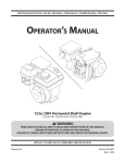
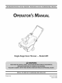
Single-Stage Snow Thrower m Moclei 2M1
MTD LLC, P.O. BOX 361131 CLEVELAND, OHiO 44136-0019
PrintedIn USA
FormNo.769-05020
(April 30,2009)
1
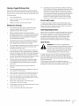
ToTheOwner
ThankYou
Thank you for purchasing
a Snow Thrower
manufactured
by
This product has met the rigid safety standards
Power Equipment
Institute and an independent
MTD LLC. It was carefully engineered to provide excellent
performance
when properly operated and maintained.
Please read this entire manual
It instructs
maintain
persons
prior to operating
you how to safely and easily set up, operate
your machine.
laboratory.
us directly.
and
website
Please be sure that you, and any other
who will operate
the machine,
carefully
follow
If you have any problems
unit, phone your local authorized
the equipment.
MTD's Customer
address and mailing
Support
Throughout
All information
is relative to the most recent
The engine
at the time of printing.
issues with regards to performance,
product
in this manual
information
available
Review
this manual frequently to familiarize yourself with the unit, its
features and operation.
Please be aware that this Operator's
warranty
may not be applicable
to all models.
telephone
satisfaction
all references
is responsible
numbers,
on this page.
at all times.
position
for all engine-related
power-rating,
and service. Please refer to the engine
Manual,
the
to right and left side of the
from the operating
manufacturer
Owner's/Operator's
more information.
Manual may cover a range of product specifications
for various
models. Characteristics
and features discussed and/or illustrated
in this manual
this manual,
are observed
concerning
address can be found
recommended
safety practices at all times. Failure to do so could
result in personal injury or property damage.
machine
or questions
MTD service dealer or contact
We want to ensure your complete
the
of the Outdoor
testing
packed separately
specifications,
manufacturer's
with your unit, for
MTD LLC
reserves the right to change product specifications,
designs and
equipment
without notice and without
incurring obligation.
1"able of Contents
Safe Operation
Practices ........................................
3
Assembly & Set-Up ..................................................
Controls & Features ...............................................
7
I0
Operation
12
................................................................
Maintenance
&Adjustment.
.................................
14
RecordProductinformation
Before setting
up and operating
in the provided
your new equipment,
Customer
dealer.
Support
you seek technical
Department,
....................................................
20
Replacement
Parts .................................................
Warranties .............................................................
21
22
DNDNDNDNDND
please
and record the
area to the right. You can locate the
model plate by standing at the operator's
down at the right rear of the snowthrower.
be necessary, should
Troubleshooting
16
19
MODEL NUMBER
locate the model plate on the equipment
information
Engine Maintenance
..............................................
Service .....................................................................
position and looking
This information
will
support
SERIAL NUMBER
via our web site,
or with a local authorized
service
DNDNDNDNDND
CustomerSupport
Please
do NOT return
If you have difficulty
the unit
assembling
this unit, you can seek help from
to the retailer
without
this product
or have any questions
the experts.
Choose
0
Visit us on the web at www.mtdproducts.com
0
Call a Customer
0
Write
Support
or dea/er
Representative
from
the options
at (800) 800-7310
us at MTD LLC • RO. Box 361131 • Cleveland,
first contacting
regarding
below:
or (330) 220-4683
OH • 44136-0019
our Customer
the controls,
Support
operation,
Department.
or maintenance
of
2
ImportantSafeOperationPractices
WARNING!
This symbol
could endanger
all instructions
points
the personal
safety and/or
in this manual
with these instructions
out important
before
property
attempting
may result in personal
When you see this symbol.
safety instructions
of yourself
to operate
which,
if not followed,
and others.
this machine.
Read and follow
Failure to comply
injury.
HEED ITS WARNING!
CALIFORNIA
PROPOSITION
65
WARNING! Engine Exhaust, some of its constituents,
and certain vehicle components
contain or emit chemicals known to State of California to cause cancer and birth defects
or other reproductive
DANGER: This machine
this manual.
operator
harm.
was built to be operated
As with any type of power
can result in serious injury. This machine
toes and feet and throwing
instructions
foreign
objects.
machine
assemble
and follow
all instructions
and in the manual(s) before
and operate.
and regular
Keep this manual
reference
on the
attempting
in a safe place for
and for ordering
replacement
foreign
1.
Never allow children under 14 years of age to operate this
machine. Children 14 and over should read and understand
and safe operation
and on the machine
adult.
5.
and be trained
Never allow adults to operate
instruction.
Thrown
objects
practices
this machine
can cause serious personal
Keep bystanders,
pets and children
machine while it is in operation.
enters the area.
Exercise caution
when operating
to avoid slipping
in reverse.
proper
injury. Plan
of material
2.
hands,
safety
performing
Do not operate
Wear footwear
surfaces.
3.
an adjustment
without
wearing
by the
operation
or repair to protect
ricochet
can cause serious
adequate
will improve
three-wire
for all machines
with electric
4.
Disengage
5.
Never attempt
winter
all control
footing
extension
outer
on slippery
cord and receptacle
start engines.
levers before
starting
to make any adjustments
except where specifically
operator's
6.
which
Use a grounded
the engine.
while
recommended
engine is
in the
manual.
Let engine and machine
before
or falling, especially
over or thrown
Always wear safety glasses or eye shields during
running,
if anyone
could be tripped
garments. Do not wear jewelry, long scarves or other loose
clothing, which could become entangled in moving parts.
at least 75 feet from the
Stop machine
which
your eyes. Thrown objects which
injury to the eyes.
by an
without
objects,
and while
in this manual
and supervised
your snow-throwing
pattern to avoid discharge
toward roads, bystanders and the like.
6.
fingers,
auger/impeller.
Be familiar with all controls and their proper operation.
Know how to stop the machine and disengage them
the instructions
4.
of amputating
Failure to observe the following
quickly.
3.
in
Thoroughly
inspect the area where the equipment
is to be used.
Remove all doormats, newspapers, sleds, boards, wires and other
to
parts.
2.
is capable
practices
or error on the part of the
Preparation
Read, understand,
future
to the safe operation
carelessness
could result in serious injury or death.
Training
1.
according
equipment,
starting
adjust to outdoor
to clear snow.
temperature
5.
SafeHandling of Gasoline
To avoid personal
in handling
injury or property
gasoline. Gasoline
vapors are explosive.
damage
is extremely
Serious personal
use extreme
flammable
a.
Use only an approved
b.
Extinguish all cigarettes,
Engine exhaust
care
and deadly
and the
6.
injury can occur when
gasoline is spilled on yourself or your clothes which
Wash your skin and change clothes immediately.
can ignite.
7.
gasoline container.
8.
cigars, pipes and other
d.
Never fuel machine
Never remove
9.
indoors.
gas cap or add fuel while
the engine
10.
Allow engine to cool at least two minutes
before
Never over fill fuel tank. Fill tank to no more than 1/2
inch below bottom
of filler
neck to provide
g.
Replace gasoline
h.
If gasoline is spilled, wipe it off the engine and
equipment.
Move machine to another area. Wait 5
i.
cap and tighten
before starting
or drugs.
Muffler
and engine
Exercise extreme
when
Exercise caution
or fuel container
to cool at least 5 minutes
inside
damage or personal
Never direct discharge
inside a vehicle
14.
Disengage power to the auger/impeller
or not in use.
15.
Never operate
or on a truck
17.
equipment
with the rim of the fuel
at all times until fueling
Do not use a nozzle lock-open
Do not put hands or feet near rotating
impeller
housing
rotating
parts can amputate
or chute assembly.
control
4
J
parts, in the auger/
20.
unsafe
easily in both directions
IMPORTANT SAFE OPERATION
all control
levers and stop engine
position
(behind
comes to a complete
making
Never put your hand in the discharge
chute assembly
while
before you
the handles). Wait
stop before
any adjustments,
or collector
openings.
engine is running.
until all moving
position
PRACTICES
Use only attachments
and accessories
manufacturer
(e.g. wheel weights,
When starting
engine,
approved
by the
tire chains, cabs etc.).
pull cord slowly until resistance
is felt, then pull rapidly. Rapid retraction of starter cord
(kickback) will pull hand and arm toward engine faster than
you can let go. Broken bones, fractures,
could result.
lever is a safety device. Never
return to the disengaged
Disengage
Shut off engine and remain behind handles
parts have stopped before unclogging.
is
Contact with the
when
Never operate with a missing or damaged chute assembly.
Keep all safety devices in place and working.
SECTION 2 --
it
Repair
device.
bypass its operation. Doing so makes the machine
and may cause personal injury.
4.
up.
If the machine should start to vibrate abnormally,
stop
the engine, disconnect
the spark plug wire and ground
Do not unclog
hands and feet.
levers must operate
speeds on
and behind and use care
unclogging
the chute assembly,
or inspections.
18.
tank or container
and automatically
released.
to clear
when transporting
at high transport
until the auger/impeller
If this
nozzle.
opening
machine
surfaces. Look down
leave the operating
from
Keep the nozzle in contact
The control
by attempting
against the engine. Inspect thoroughly
for damage.
any damage before starting and operating.
19.
3.
and pets or
away from your vehicle
remove gas-powered
dispenser
The auger/impeller
bystanders
in front of the machine.
Never operate this machine without good visibility or light.
Always be sure of your footing and keep a firm hold on the
handles. Walk, never run.
Operation
2.
at children,
caused by a ricochet.
13.
is not possible, then refuel such equipment
on a
trailer with a portable container, rather than from a
1.
injury
Do not overload machine capacity
snow at too fast of a rate.
bed with a plastic liner. Always place
complete.
and while
before
the truck or trailer and refuel it on the ground.
m.
direction
12.
16.
containers on the ground
before filling.
gasoline
when changing
on or crossing
hazards or traffic.
Plan your snow-throwing
pattern to avoid discharge
towards windows, walls, cars etc. Thus, avoiding possible
slippery
Never fill containers
If possible,
operating
on slopes.
when backing
I.
of
hot and can cause a burn. Do
away.
caution
the influence
is an open flame, spark or pilot light
Allow machine
storing.
or trailer
become
not touch. Keep children
allow anyone
dryer etc.).
k.
while under
area.
an odorless
securely.
(e.g. furnace, water heater, space heater, clothes
j.
monoxide,
the engine.
Never store the machine
where there
11.
space for
fuel expansion.
minutes
machine
alcohol
property
refueling.
f.
or in a poorly ventilated
carbon
gas.
Do not operate
operating
is
hot or running.
e.
indoors
contains
gravel surfaces. Stay alert for hidden
sources of ignition.
C.
Never run an engine
21.
If situations
occur which
are not covered
bruises or sprains
in this manual,
care and good judgment.
Contact Customer Support for
assistance and the name of your nearest servicing dealer.
use
14.
Clearinga CloggedDischargeChute
Hand contact
with the rotating
impeller
According
to the Consumer
inside the discharge
Life have the machine
systems are working
1.
SHUTTHE ENGINE OFF!
2.
Wait 10 seconds to be sure the impeller
stopped rotating.
3.
Always use a clean-out
Never tamper
tool, not your hands.
To avoid serious injury
with safety devices. Check their proper
regularly.
Refer to the maintenance
sections
Before cleaning,
disengage
repairing,
the auger/impeller
or inspecting
come to a complete
to keep the machine
Also, visually
4.
5.
inspect
improper
Maintain
EPA emission
in any
to
to comply with California
and federal
for SORE (Small Off Road Equipment)
on regular
unleaded
emission
control
gasoline,
and
systems: Engine
at frequent
in safe working
condition.
Spark Arrestor
for any damage.
i_ll
frequently
and replace with original
and compromise
levers periodically
or replace
are certified
regulations
the engine
equipment
safety!"
to verify they engage
safety and instruction
internal combustion
engine and should not be used
WARNING!
machine isforest-covered,
equipped with brush
an
on or near anyThis
unimproved
covered or grass-covered
land unless the engine's
exhaust
system is equipped
meeting
applicable
Ira spark arrester is used, it should
working
order by the operator.
with a spark arrester
local or state laws (if any).
be maintained
in effective
In the State of California
the
above is required by law (Section 4442 of the California Public
Resources Code). Other states may have similar laws. Federal laws
and disengage properly and adjust, if necessary. Refer
to the adjustment
section in this operator's manual for
instructions.
7.
of engine
the following
For your safety protection,
performance
Check control
engine
can lead to a runaway
at unsafe speeds. Never tamper
setting
to operate
manufacturer's
(OEM) parts only. "Use of parts which do
not meet the original equipment
specifications
may lead to
6.
setting
Modification
(EM), Oxidizing Catalyst (OC), Secondary Air
Injection (SAI) and Three Way Catalyst (TWC) if so equipped.
machine
check all components
or death.
governor.
shave plates and skid shoes are subject to
wear and damage.
injuries
with factory
may include
speed of the engine.
Snow thrower
and safety
engine and cause it to operate
Engines which
Wait until
Do not change the engine governor setting or over-speed
the engine. The governor controls the maximum safe
operating
by an authorized
and not worn excessively.
or death, do not modify
are certified
Check bolts a nd screws for proper tightness
intervals
properly
with the governor
stop. Disconnect
against
(EPA),
Notice RegardingEmissions
machine
levers and stop the engine.
the spark plug wire and ground
prevent unintended
starting.
3.
and
of this manual.
all control
Agency
Donot modifyengine
Maintenance & Storage
2.
annually
Failure to do so can result in accidents,
blades have
way. Tampering
adjustment
inspected
service dealer to ensure that all mechanical
To clear the chute:
operation
Safety Commission
Protection
this product has an Average Useful Life of seven (7) years,
or 60 hours of operation. At the end of the Average Useful
chute is the most common cause of injury associated with snow
throwers. Never use your hand to clean out the discharge chute.
1.
Products
(CPSC) and the U.S. Environmental
apply on federal
lands.
A spark attester for the muffler
is available
through
your
nearest engine authorized service dealer or contact the service
department,
RO. Box 361131 Cleveland, Ohio 44136-0019.
labels, as
necessary.
8.
Observe proper disposal laws and regulations
etc. to protect the environment.
9.
Prior to storing,
from machine
10.
run machine
and prevent
Never store the machine
a few minutes
heater, furnace,
or fuel container
12.
inside where
light such as a water
clothes dryer etc.
Always refer to the operator's
instructions
to clear snow
freeze up of auger/impeller.
there is an open flame, spark or pilot
11.
for gas, oil,
on off-season
manual
for proper
storage.
Check fuel line, tank, cap, and fittings
frequently
for cracks
or leaks. Replace if necessary.
13.
Do not crank engine with spark plug removed.
SECTION
2 --
IMPORTANT
SAFE
OPERATION
PRACTICES
S
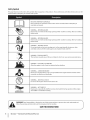
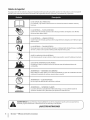
Safety Symbols
This page depicts and describes safety symbols that may appear
machine before attempting
to assemble and operate.
on this product.
Read, understand,
and follow
all instructions
on the
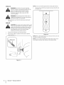
READ THE OPERATOR'S MANUAL(S)
Read, understand,
assemble
and follow
all instructions
in the manual(s) before
WARNING--
WARNING--
WARNING--
Contact
with the rotating
WARNING--THROWN
This machine
WARNING--
machine
is running.
There are rotating
parts, in the auger/impeller
and muffler
IS FLAMMABLE
before refueling.
or in a poorly ventilated
area. Engine exhaust contains carbon
electric starter in the rain
the muffler,
become extremely
hot during
operation.
Allow engine
to cool before touching.
Your Responsibility--Restrict
the use of this power machine
to persons
in this manual and on the machine.
SAVETHESEINSTRUCTIONS!
IMPORTANT SAFE OPERATION
injury.
HOT SURFACE
Engine parts, especially
SECTION 2 --
can cause serious personal
ELECTRICAL SHOCK
WARNING--
I
or chute
an odorless and deadly gas.
Do not use the engine's
6
housing
hands and feet.
CARBON MONOXIDE
WARNING--
and instructions
while
OBJECTS
Never run an engine indoors
the warnings
There are rotating
parts can amputate
Allow the engine to cool at least two minutes
follow
is running.
may pick up and throw and objects which
WARNING--GASOLINE
monoxide,
machine
ROTATING AUGER
Do not put hands or feet near rotating
assembly.
while
ROTATING BLADES
Keep hands out of inlet and discharge openings
blades inside
WARNING!
to
ROTATING BLADES
Keep hands out of inlet and discharge openings
blades inside
........
!i........
attempting
and operate
PRACTICES
who read, understand
and
3
Assembly
& Set-Up
One 20 oz. Bottle 5W-30 Oil
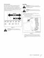
NOTE: All references
are from
the operator's
to the left or right side of the snow thrower
position.
Any exceptions
will be noted.
2.
One Snow Thrower Operator's
Manual
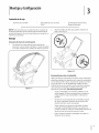
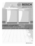
Tighten
the wing
knobs to secure the handle in place.
See Fig. 3-2.
Assembly
Positioningthe Upper Handle
1.
Pivot the upper
handle into the operating
position
making
sure not to pinch the cable in the process, as illustrated
in
Fig. 3-1 until it clicks into place.
Figure 3-2
FuelRecommendations
Use automotive
combustion
Gasoline with
Figure 3-1
gasoline
chamber
(unleaded
deposits)
or low leaded to minimize
with a minimum
up to 10% ethanol
of 87 octane.
or 15% MTBE (Methyl
Tertiary
Butyl Ether) can be used. Never use an oil/gasoline
mixture or
dirty gasoline. Avoid getting dirt, dust, or water in the fuel tank.
DO NOT use E85 gasoline.
Refuel in a well-ventilated
area with the engine stopped.
Do not smoke or allow flames or sparks in the area where
the engine
is refueled
Do not overfill
or where gasoline is stored.
the fuel tank. After refueling,
tank cap is closed properly
Be careful not to spill fuel when
fuel vapor may ignite.
area is dry before
Avoid repeated
breathing
refueling.
Spilled fuel or
If any fuel is spilled,
make sure the
starting
the engine.
or prolonged
of vapor.
make sure the
and securely.
contact
with skin or
NOTE: Do not screw in the dipstick
Adding Fuel
WARNING!
Use extreme
gasoline. Gasoline
care when
is extremely
vapors are explosive.
handling
flammable
3.
Slowly add oil until the level registers
high (H) and
H
sources of ignition.
starting
between
the oil level.
f
indoors or while the engine is hot or running.
Extinguish cigarettes, cigars, pipes and other
WARNING!
equipment
checking
low (L) Fig. 3-4.
and the
Never fuel the machine
when
Always keep hands and feet clear of
moving parts. Do not use a pressurized
fluid. Vapors are flammable.
Remove the gas cap, check the fuel level and add fuel if
necessary.
Adding Oil
CAUTION:
amount
The engine
may be shipped
oil in the engine.
with a small
You must be sure to fill the
engine with oil between the high and low marks on
the dipstick before operating.
Running the engine
with insufficient
oil can cause serious engine
damage and void the engine warranty.
1.
Place the snow thrower
on a flat, level surface.
2.
Remove the oil filler cap/dipstick
clean. See Fig. 3-3.
and wipe the dipstick
Figure 3=4
NOTE: Refer to the Engine Maintenance
viscosity
Figure
I
SECTION3--
section for the correct oil
oil capacity.
NOTE: Do not overfill. Overfilling the engine with oil may result
in the engine smoking, hard starting or spark plug fouling.
_erLeve!
8
and engine
ASSEMBLY&
3-3
SET-UP
Adjustments
ChuteAssembly
The pitch of the chute assembly controls the angle at which the
snow isthrown.
1.
Loosen the wing knob found on the left side of the chute
assembly and pivot the upper chute upward or downward
to the desired pitch, Retighten the wing knob before
operating the snow thrower,
2.
Position the chute assembly opening by using the chute
handle to throw the snow in the desired direction, See Fig.
3-5.
f
/
S
//
i /
J
Figure 3-5
SECTION 3 --
ASSEMBLY& SET-UP
9
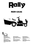
4
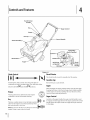
Controls
and Features
f
Recoil Starter
Handle
er Control
Gas Cap
Chute Assernbl
f
Spark Plug/
/
Spark Plug Boot
Exhaust_
Shave Plate
Auger
Oil Fill Cap__--\\\
_t//_.
w/Dipstick
_/
Oil Drain f "
--
Recoil
"Starter
Hand/e)
Figure 44
RecoilStarter
ChokeControl
! I
!_ltb
Activating
the choke control
carburetor
and aids in starting
between
the RUNI _
closes the choke plate on
engine. The choke lever slides
landc,o,,l -I pos,t,ons.
!
_
The starter
handle is used to manually
GasolineCap
Remove the gas cap to add fuel.
Auger
When engaged,
housing
Primer
come in contact
The key is a safety device. It must be fully inserted
in
order for the engine to start. Remove the key when
engine.
'°1
Doing so may cause it to break.
draws snow into the auger
it out the discharge
chute. Rubber paddles
the snow thrower
as they
with the pavement.
AugerControl
Located
the snow thrower is not in use.
NOTE: Do not turn the key in an attempt
the augers rotation
and throws
on the augers also aid in propelling
Pressing primer forces fuel directly into engine's
carburetor to aid in cold-weather
starting.
start the engine.
handle, the auger control
handle is used
drive to the auger. Squeeze the control
handle against the upper
handle to engage the auger; release it
to disengage.
f_O
to start the
on the upper
to engage and disengage
ChuteAssembly
Rotate the discharge chute to the left or right using the chute
handle. The pitch of the discharge chute controls the angle at
which the snow is thrown.
the discharge
Loosen the wing knob on the side of
chute before
or downward.
Retighten
been achieved.
pivoting
the discharge
the knob once the desired
chute upward
position
has
ShavePlate
The shave plate maintains
the snow thrower
pavement's
contact
is propelled,
with the pavement
allowing
as
snow close to the
surface to be discharged.
SECTION
4 -- CONTROLS
AND
FEATURES
11
Operation
BeforeStarting
9_
As the engine warms up and begins to operate evenly, slide
the choke lever slowly to the 1/2-choke(mid-way between
RUNI _ land CHOKEI_kl)position.
instructions
WARNING!
this manual
_
1.
and
warnings
on theand
machine
Read,
understand
follow
before operating.
The spark plug wire was disconnected
and
all thein
for safety. Attach
begins to run smoothly, move the choke to the RUN I _ I
position. If the engine falters, return to CHOKEI_IKI, then
the
spark plug wire to the spark plug before starting.
slowly move to 1/2-chokethen the RUNI _ I position.
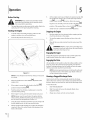
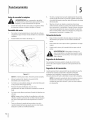
Starting the Engine
1.
2.
When the engine
Stopping the Engine
To avoid carbon monoxide
poisoning,
engine is outdoors in a well-ventilated
make sure the
area.
1.
Run the engine for a few minutes
dry off any moisture
Insert the key into the slot. See Fig. 5-1.
before stopping
to help
on the engine.
2.
To stop the engine remove
place.
the key and store it in a safe
3.
Wipe all the snow and moisture
from the area around
the
engine.
become
hot and can cause a burn. Be careful and do
ARNING!
Muffler, engine and surrounding
areas
not touch when they are hot.
_
Engaging the Auger
Engage the auger by squeezing the auger control against the
upper handle. Release the control to stop the auger.
Engaging the Drive
Lift up slightly
on the handle to allow the rubber
paddles
on the
auger to contact the pavement and propel the snow thrower
forward. Pushing downward
on the handle will raise the auger
offthe
ground
and stop the forward
NOTE: Excessive upward
in premature
Figure 5-1
NOTE: Do not attempt
it to break.
not be covered
to turn the key. Doing so may cause
Move the choke lever to the CHOKE I_1
position
(cold
engine start).
4.
If the engine
position
5.
6.
instead of CHOKE
I -I.
Push the primer
five (5) times, making
vent hole when
pushing.
If the engine
NOTE:Always
is warm, push the primer
sure to cover the
button
cover the vent hole in the primer
only once.
button
when pushing. Additional
priming may be necessary
the first start if the temperature
is below 15° F.
7.
8.
Grasp the starter
for
handle and pull the rope out slowly, until
it pulls slightly
harder. Let the rope rewind
Pull the starter
handle rapidly.
snap back. Allow it to rewind
hold on the handle.
slowly.
Do not allow the handle to
slowly while keeping
a firm
blades which
are
by the warranty.
with the rotating
chute is the most common
throwers.
is warm, place the choke in the RUN I _ I
pressure on the handle will result
wear on the rubber auger
Clearinga CloggedDischargeChute
Hand contact
3.
motion.
impeller
cause of injury
inside the discharge
associated
with snow
Never use your hand to clean out the discharge
To clear the chute:
1.
SHUTTHE ENGINE OFF!
2.
Wait 10 seconds to be sure the impeller
stopped
3.
blades have
rotating.
Always use a clean-out
tool, not your hands.
chute.
SECTION
5 --
OPERATION
13
Maintenance& Adjustments
Adjustments
5_
WARNING!
Before Servicing,
inspecting
the snow thrower,
repairing
disengage
If the starter
is difficult
to pull, remove the spark plug and
pull the handle several times to ensure that any oil trapped
in the head is removed.
or
the auger
control. Stop the engine and remove the key to
prevent unintended
starting.
when
_
it is removed and the starter handle is pulled.
may come out of the spark plug hole
AUTION: Oil
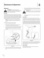
ShavePlate
To check the adjustment
of the shave plate, place the machine
on a level surface. The wheels, shave plate and auger should all
contact
wears out excessively,
or the snow thrower
If the shave plate
does not self-propel,
the shave plate may be too low and needs to be adjusted.
NOTE:On
new snow throwers
shave plate installed,
or machines
off the
as follows:
upper
Drain the gas from
2.
Pull the starter cord until resistance is felt. Then tip the
snow thrower back until it rests on the handles.
the snow thrower.
Loosen the four lock nuts and bolts which
to the desired
position
As a result of both the control
cable and the auger
drive belt
hole in the control
handle provides
If
for an adjustment
in cable tension. To adjust, disconnect
the end of control cable
from the bottom hole in the control handle and reinsert it in the
1.
plate to the housing.
Control Cable
The upper
ground.
To adjust the shave plate proceed
the spa rk plug. If it is wet, clean off any oil before
stretching due to wear, periodic adjustments
may be necessary.
the auger seems to hesitate when rotating, proceed as follows:
with a new
the auger may be slightly
Inspect
re-installing.
the level surface. Note that if the shave plate is adjusted
too high, snow may blow under the housing.
3_
6_
hole. Insert the cable from the outside
as shown in Fig. 6-2.
f
Control
Handle
secure the shave
See Fig. 6-1. Move the shave plate
and retighten
the nuts and bolts
securely.
/
Figure 6=2
Test the snow thrower
to see if there
is a noticeable
difference.
If
after the adjustment
to the control cable the auger still hesitates
when rotating, see the Service Section for instructions
on
replacing
the belt.
ChuteAssembly
Figure 6-1
4_
Tip the snow thrower
pull the starter
pull.
back to the operating
Refer to the Assembly
position
handle a few times to see if it is difficult
and
to
adjusting
& Set-Up section
the chute assembly.
for instructions
on
Maintenance
Lubrication
Lubricate
the pivot points
extension
spring at the end of the control
on the control
handle and the
cable with a light
oil once every season and before the snow thrower
storage at the end of the season.
is put into
0ff-SeasonStorage
If the snow thrower will not be used for 30 days or longer, follow
the instructions
below.
1.
Store the equipment
in a clean, dry area.
2.
If storing the snow thrower
rustproof the machine
the snow thrower.
3.
Clean the exterior
in an unventilated
area,
using a light oil or silicone
to coat
of the engine and the snow thrower.
SECTION 6 --
MAINTENANCE
& ADJUSTMENTS
15
7
EngineMaintenance
Periodic
i_ll
inspection
and adjustment
high level performance
the engine and remove the key before performing
WARNING!
To prevent
accidental start-up, shut off
any
type of engine
maintenance.
of the engine is essential
is to be maintained.
if
Regular maintenance
will also ensure a long service life. The required
service intervals
and the type of maintenance
to be performed are described
in the table below. Follow the hourly or calendar intervals,
whichever
occur first. More frequent
operating
in adverse
service is required
when
conditions.
MaintenanceSchedule
Tasks
Firsts
Hrsl
'
Check engine
EaChuse or
Every 5 Hrs.
oil
EverY Season
or2S Hrs.
I
I
I
Check spark plug
6.
Oil Level in the Operation
Drain fuel from
the tank by running
fuel tank is empty.
3.
Place a suitable
the engine until the
Be sure the fuel fill cap is secure.
oil collection
7.
Reinstall
the oil filler cap/dipstick
container
ll_
under the oil drain
NOTE:
friendly to the environment.
collection center.
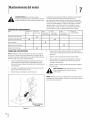
Tip the engine to drain oil into the container.
Reinstall
of at a proper
collection
the drain plug and tighten
securely.
and water as soon as possible after handling
CAUTION:
used oil.
Thoroughly
wash your hands with soap
Remove the oil drain plug, Figure 7-1.
be disposed
oil and check the oil level,
& Set-Up Section for instructions.
plug.
Figure 7-1
5.
Refill with the recommended
Section
Oil Drain Plug
4.
I
refer to Assembly
NOTE: Check the oil level before each use and after every five
hours of operation to be sure the correct oil level is maintained.
2.
I
•
(hanging Engine0il
1.
-
®
area
Refer to Checking
Every Season
or 100 Hrs.
®
change engine oil'
Clean exhaust
Every Season,
or SO Hrs.
Used oil must
center.
it securely.
Please dispose of used motor
oil in a manner
Take it to a recycling
that is
center or other
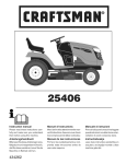
Oil Recommendations
When adding
Spark Plug
oil to the engine,
refer to the viscosity
chart
below (Fig. 7-2). Engine oil capacity
is 600 ml (approx. 20
oz.). Do not over-fill.
or an equivalent
Use a 4-stroke,
high
_hll
spark plug removed. DO NOT crank the engine with
NOT check for a spark with the
theARNING!
spark plugDOremoved.
_
muffler will be very hot. Be careful not to touch the
muffler.
ARNING!
If the engine has been running, the
detergent, premium quality motor oil certified to meet or
exceed U.S. automobile
manufacturer's
requirements
for service
classification
designation
SG, SF.Motor
oils classified
SG, SF will show this
on the container.
To ensure proper
engine operation,
properly
and free of deposits.
1.
gapped
the spark plug must be
Remove the spark plug boot and use a spark plug wrench
to remove the plug, Fig. 7-3.
!
("F)-400-200 0o 200 400
("C)
-30° -20° -I0 ° 0°
Figure 7-2
/
2-stroke engine oil. It could shorten the engine's
CAUTION:
service life. DO NOT use non-detergent
oil or
J
_
Spark
Plug Boot
Figure 7-3
2.
Visually inspect the spark plug. Discard the spark plug if
there is any apparent wear, or if the insulator is cracked or
chipped.
reused.
Clean the spark plug with a wire brush if it is to be
SECTION
7 -- ENGINEMAINTENANCE
17
3.
Measure the plug gap with a feeler gauge. Correct as
necessary by bending the side electrode,
should be set to .02-.03 inches (0.60-0.80
Fig. 7-4. The gap
mm).
f
Off-SeasonStorage
Engines stored over 30 days need to be drained of fuel to
prevent deterioration
and gum from forming in the fuel
system or on essential
engine deteriorates
carburetor,
carburetor
during
parts. If the gasoline in your
storage, you may need to have the
and other fuel system components,
serviced
or
replaced.
Electrode
1.
Remove all fuel from the tank by running
the engine
until
it stops.
2.
Change the engine
3.
Remove the spark plug and pour approximately
oil.
1 oz. (30
ml) of clean engine oil into the cylinder. Pull the recoil
starter several times to distribute
the oil, and reinstall the
spark plug.
4.
4====== .02-.03
(0.60-0.80
in.
ram)
Clean debris from around
the engine,
and under, around,
and behind the muffler. Apply a light film ofoil
areas that are susceptible to rust.
5.
on any
Store in a clean, dry and well ventilated area away from any
appliance that operates with a flame or pilot light, such as a
furnace, water heater or clothes dryer. Avoid any area with
a spark producing
4.
Check that the spark plug washer is in good condition
6.
If possible,
and thread
7.
Keep the engine
the spark plug in by hand to prevent
cross-
threading.
5.
to compress
NOTE:When
with a spark plug
the washer.
installing
a new spark plug, tighten
after the spark plug seats to compress
1/2-turn
the washer. When
reinstalling
a used spark plug, tighten Ys- to 1/4-turn after
the spark plug seats to compress the washer.
securely. A loose spark plug can become very hot
CAUTION:
The spark
plug must be tightened
and
can damage
the engine.
Cleaning the Engine
If the engine
has been running,
an hour before
avoid storage
cleaning.
allow it to cool for at least half
Periodically
remove dirt build-up
from
engine.
CAUTION:
Do not spray the engine with water to
clean it because the water could contaminate
the
fuel. Using a garden
equipment
opening.
Water that passes through
WARNING!
muffler
hose or pressure washing
can also force water into the muffler
enter the cylinder
can
of debris around
the
could cause a fire. Inspect and clean before
every use.
SECTION
7--
the muffler
and cause damage.
Accumulation
ENGINE MAINTENANCE
motor,
or where power tools are
areas with
high humidity.
level in storage. Tilting
cause fuel or oil leakage.
After the spark plug is seated, tighten
wrench
electric
operated.
Figure 7-4
the engine
can
Service
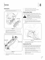
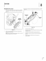
ReplacingBelt
1.
Remove the belt cover by removing the five hex screws
that secure it to the frame. See Fig. 7-1.
3.
Route the belt around
the engine
4.
Push the belt over the bottom
5.
Reinstall
pulley.
of the auger
the belt cover removed
pulley.
earlier.
ReplacingAugerPaddles
The snow thrower
and should
auger's
be replaced
are subject to wear
paddles to wear to the point where portions of the
CAUTION:
metal auger Do
itselfNOT
canallow
comethe
in auger's
contact rubber
with the
i_[i
pavement.
Hex
rubber paddles
if any signs of excessive wear are present.
Screws
Doing so can result in serious damage to
your snow thrower.
To change
1.
the rubber
paddles,
Remove the existinc
self-tapping
Fig. 7-3.
proceed
rubber
screws which
as follows:
paddles
by unthreading
the
secure them to the auger. See
f
'\
//
\
//
.........
s
Figure 7-1
/
2.
Remove the belt by grasping
auger pulley and pulling
NOTE: Push down
it from the bottom
of the
outward.
on the idler puller to release the belt
from under the belt keeper. See Fig. 7-1.
To replace the belt follow
these instructions
and refer to Fig. 7-2:
k_
Self-Tapping
'ulley
Screws
J
Figure 7-3
2.
Secure the replacement
the hardware removed
rubber
earlier.
paddles
to the auger using
ReplacingShavePlate
The shave plate is attached
to the bottom
and is subject to wear. It should
are two wearing
1.
Push down
2.
Position
2.
Install the new shave plate, making
3.
4.
Adjust the shave plate as instructed
Tighten
sure the heads of the
bolts are on the inside of the housing.
Adjustments
pulley and under the
There
Remove the four carriage bolts and hex lock nuts which
attach it to the snow thrower housing.
on the idler pulley.
the belt on top of the auger
periodically.
edges and the shave plate can be reversed.
1.
carriage
Figure 7-2
of the auger housing
be checked
in the Maintenance
&
Section.
securely once adjusted.
belt keeper.
19
9
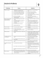
Troubleshooting
Problem
Cause
Engine Fails to start
1. Fuel tank empty, or stale fuel.
1. Fill tank with clean fresh gasoline.
2. Blocked fuel line.
2. Clean fuel line.
3. Key not inserted
Engine running erratically/
inconsistent RPM (hunting
or surging)
Remedy
all the way.
3. Insert key all the way.
4. Spark plug wire disconnected.
4. Connect wire to spark plug.
S. Faulty spark plug.
5. Clean spark plug, readjust
6. Engine not primed.
6. Prime engine five times.
7. Engine flooded
from excessive priming.
7. Wait at least ten minutes
1. Engine running
on choke.
1. Move choke lever to RUN position.
2. Fuel line blocked, or stale fuel.
gap, or replace.
before starting.
2. Clean fuel line and fill tank with fresh, clean
gasoline.
3. Water or dirt in fuel system.
3. Run engine until it stops. Refill with fresh fuel.
4. Carburetor
4. Contact an authorized
service center.
5. Contact an authorized
service center.
1. Contact an authorized
service center.
out of adjustment.
5. Over-governed
engine.
Engine overheats
1. Carburetor
Loss of power
1. Spark plug wire loose.
2. Ventin
Excessive vibration
out of adjustment.
1. Firmly connect
2. Clear vent.
gas cap plugged.
1. Loose parts or damaged
spark plug wire.
auger.
1. Stop engine immediately
and disconnect
spark plug wire. Check for possible damage.
Tighten
all bolts and nuts. Repair as needed.
If the problem persists, take snow thrower
an authorized service dealer.
Snow thrower
fails to self-
1. Auger control cable out of adjustment.
1. Adjust auger control cable as shown in
Maintenance & Adjustments section.
2. Auger drive belt loose or damaged.
2. Replace auger drive belt.
1. Auger control cable out of adjustment.
1. Adjust auger control cable as shown in
propel
Augers continue
to rotate
Maintenance
Unit fails to discharge
snow
1. Chute assembly
2. Foreign object
& Adjustments
to
section.
1. Stop engine and disconnect spark plug wire.
Clean chute and inside of auger housing with
clean-out tool or stick.
clogged.
lodged in auger.
2. Stop engine immediately
and disconnectthe
spark plug wire. Remove object from auger.
Engine fails to start
3. Auger control cable out of adjustment.
3. Adjust auger control cable.
4. Auger belt loose or damaged.
4. Replace auger belt.
1. Extension
cord not connected
electric start button,
on models
(when using
so equipped)
1. Connect one end of the extension cord to
the electric starter outlet and the other end
to a three-prong
outlet.
120-volt, grounded,
AC
1
Replacement
Parts
Component
l
j
Part Number
and Description
731-1033
Shave Plate
954-0101A
BeltV-Type
735-04032
735-04033
753-04472
Spiral Crescent
Rubber Paddle
731-05632
Key
746-04237
Clutch Cable
951-10292
Spark Plug
Replacement Kit (includes 4 crescents,
2 paddles and hardware)
/
/
/
Phone (800) 800-7310 to order replacement
Parts Manual
downloads
are also available
parts or a complete
Parts Manual
(have your full model number
and serial number
ready).
free of charge at www.mtdproducts.com.
21
MTD CONSUMER GROUP INC (MTD), the California Air Resources Board (CARB)
and the United States Environment Protection Agency (U. S. EPA)
Emission
(Owner's
Control System Warranty
Defect Warranty
Statement
Rights and Obligations)
EMISSIONCONTROLSYSTEMCOVERAGEIS APPLICABLETOCERTIFIEDENGINESPURCHASEDIN CALIFORNIAIN 2005 ANDTHEREAFTER,WHICHARE USEDIN CALIFORNIA,ANDTO CERTIFIEDMODELYEAR2005 AND LATERENGINESWHICHARE PURCHASEDAND
USEDELSEWHEREIN THE UNITEDSTATES.
Californiaand elsewherein the UnitedStatesEmissionControlDefectsWarrantyCoverage
The CaliforniaAir ResourcesBoard(CARB),U. S. EPAand MTDare pleasedto explaintheemissionscontrol systemwarrantyon your modelyear
2006 and latersmalloff-roadengine.In California,new smalloff-roadenginesmustbe designed,builtand equippedto meet theStatesanti-smog
standards.Elsewherein the UnitedStates,newnon-road,spark-ignitionenginescertifiedfor model2005and later,mustmeet similarstandardsset
forth by the U. S. EPA.MTDmustwarrantythe emissioncontrolsystemon yourenginefor the periodof time listed below,providedtherehasbeen
no abuse,neglector impropermaintenanceof your smalloff-roadengine.
Youremissioncontrolsystemmay includepartssuch as the carburetor,fuel-injectionsystem,the ignitionsystem,and catalyticconverter,fueltanks,
fuel lines,fuel caps,valves,canisters,filters,vaporhoses,clamps,connectors,and otherassociatedemission-relatedcomponents.
Wherea warrantableconditionexists,MTDwill repairyoursmall off-roadengineat no cost to yourincludingdiagnosis,partsand labor.
MANUFACTURER'S
WARRANTY COVERAGE:
This emissionscontrolsystemis warrantedfor two years.If anyemission-relatedpart on yourengine is defective,the part will be repairedor
replacedby MTD.
OWNER'S WARRANTY
RESPONSIBILITIES:
As the smalloff-roadengineowner,youare responsibleforthe performanceof the requiredmaintenancelisted in your Owner'sManual.MTD
recommendsthat you retainall yourreceiptscoveringmaintenanceson yoursmall off-roadengine,but MTDcan not denywarrantysolelyfor the
lack of receiptsor foryour failureto ensurethe performanceto all scheduledmaintenance.
As the smalloff-roadengineowner,youshouldhoweverbe awarethat MTDmaydenyyour warrantycoverageif yoursmall off-roadengine or part
hasfaileddue toabuse, neglect,impropermaintenanceor unapprovedmodifications.
Youare responsiblefor presentingyour smalloff-roadengineto an AuthorizedMTDServiceDealeras soonas a problemexists.Thewarranted
repairsshouldbe completedin a reasonableamountof time,notto exceed30 days.
If you haveanyquestionsregardingyourwarrantyrightsand responsibilities,you shouldcontacta MTDService Representativeat 1-800-800-7310
and addressis MTDCONSUMERGROUP,RO. Box361131,ClevelandOH,44136-0019.
DEFECTS WARRANTY
REQUIREMENTS
FOR 1995 AND LATER SMALL OFF-ROAD ENGINES:
This sectionappliesto 1995and later smalloff-roadengines.The warrantyperiodbeginson the datethe engineor equipmentis deliveredto an
ultimatepurchaser.
(a) GeneralEmissionsWarrantyCoverage
MTDmustwarrantto the ultimatepurchaserand eachsubsequentpurchaserthat the engineis:
(1) Designed,built,and equippedsoas to conformwith all applicableregulationsadoptedby the Air ResourcesBoardpursuantto its authorityin
Chapters1 and 2,Part 5, Division26 of the Healthand SafetyCode; and
(2) Freefrom defectsin materialsand workmanshipthat causethe failureof a warrantedpart to be identicalin all materialrespectsto the partas
describedin theengine manufacturer'sapplicationfor certificationfora periodof two years.
(b) The warrantyon emissions-relatedpartswill be interpretedas follows:
(1) Anywarrantedpart that is not scheduledfor replacementas requiredmaintenancein the writteninstructionsrequiredby Subsection(c)
mustbe warrantedfor the warrantyperioddefinedin Subsection(a)(2). If any such partfails duringthe periodof warrantycoverage,it mustbe
repairedor replacedby MTDaccordingto Subsection(4) below.Anysuch part repairedor replacedunder thewarrantymustbe warrantedfor
the remainingwarrantyperiod.
(2) Any warrantedpartthat is scheduledonlyfor regularinspectionin the writteninstructionsrequiredby Subsection(c) must be warrantedfor
thewarrantyperioddefinedin Subsection(a)(2).A statementin such writteninstructionsto the effectof "repairor replaceas necessary"will
not reducethe periodof warrantycoverage.Anysuch part repairedor replacedunderwarrantymustbe warrantedforthe remainingwarranty
period.
(3) Anywarrantedpartthat whichis scheduledfor replacementas requiredmaintenancein the writteninstructionsrequiredby Subsection(c)
mustbe warrantedfor the periodd time prior to the first scheduledreplacementpointforthat part. If the part fails priorto thefirst scheduled
replacement,the part mustbe repairedor replacedby MTDaccordingto Subsection(4) below.Any suchpart repairedor replacedunder
warrantymustbe warrantedfor the remainderof the period priorto the first scheduledreplacementpointfor the part.
(4)Repair
orreplacement
ofanywarranted
partunder
thewarranty
provisions
ofthisarticle
must
beperformed
atnocharge
totheowner
ata
warranty
station.
(5)Notwithstanding
theprovisions
ofSubsection
(4)above,
warranty
services
orrepairs
must
beprovided
atallMTD
distribution
centers
that
arefranchised
toservice
thesubject
engines.
(6)Theowner
must
notbecharged
fordiagnostic
laborthatleads
tothedetermination
thatawarranted
partisinfactdefective,
provided
that
suchdiagnostic
workisperformed
atawarranty
station.
(7)Theengine
manufacturer
isliable
fordamages
toother
engine
components
proximately
caused
byafailure
under
warranty
ofanywarranted
part.
(8)Throughout
theengine's
warranty
period
defined
inSubsection
(a)(2),
MTD
willmaintain
a supply
ofwarranted
partssufficient
tomeet
the
expected
demand
forsuchparts.
(9)Anyreplacement
partmaybeused
intheperformance
ofanywarranty
maintenance
orrepairs
andmust
beprovided
without
charge
tothe
owner.
Suchusewillnotreduce
thewarranty
obligations
ofMTD.
(10)Add-on
ormodified
partsthatarenotexempted
bytheAirResources
Board
maynotbeused.
Theuseofanynon-exempted
add-on
or
modified
parts
shallbegrounds
fordisallowing
awarranty
claim
made
inaccordance
withthisarticle.
Theengine
manufacturer
shallnotbe
liable
under
thisarticle
towarrant
failures
ofwarranted
partscaused
bytheuseofnon-exempted
add-on
ormodified
part.
(c) MTDwill includea copy of the followingemissionwarrantyparts list with each newengine,usingthose portionsof the list applicableto the
e__&gine.
(1) FuelMeteringSystem
• Coldstart enrichmentsystem(soft choke)
,,Carburetor
andinternalparts
• Fuel Pump
• FuelTank
(2) Air InductionSystem
• Air cleaner
• Intakemanifold
(3) IgnitionSystem
• Sparkplug(s)
• MagnetoIgnitionSystem
(4) ExhaustSystem
Catalyticconverter
• SAI (Reedvalve)
(5) MiscellaneousItemsUsedin AboveSystem
Vacuum,temperature, position,time sensitivevalvesand switches
Connectorsand assemblies
(6) Evaporativecontrol
• Fuel Hosecertifiedfor ARBevaporativeemissionof 2006.
• Fuel HoseClamps
Tetheredfuel cap
Carboncanister
Vaporlines
GD0C-100174Rev.B
MANUFACTURER'S
LiMiTED WARRANTY
The limited warranty set forth below is given by MTD LLC with
respect to new merchandise purchased and used in the United States
and/or its territories and possessions, and by MTD Products Limited
with respect to new merchandise purchased and used in Canadaand/
or its territories and possessions (either entity respectively, "MTD").
"MTD" warrants this product (excluding its Normal Wear Parts and
Attachments as described below) against defects in material and
workmanship for a period of two (2) years commencing on the date
of original purchase and will, at its option, repair or replace, free of
charge, any part found to be defective in materials or workmanship.
This limited warranty shall only apply if this product has been
operated and maintained in accordance with the Operator's Manual
furnished with the product, and has not been subject to misuse,
abuse, commercial use, neglect, accident, improper maintenance,
alteration, vandalism, theft, fire, water, or damage because of other
peril or natural disaster. Damage resulting from the installation or use
of any part, accessory or attachment not approved by MTD for use
with the product(s) covered by this manual will void your warranty as
to any resulting damage.
Normal Wear Parts are warranted to be free from defects in material
and workmanship for a period of thirty (30) days from the date of
purchase. Normal wear parts include, but are not limited to items
such as: batteries, belts, blades, blade adapters, tines, grass bags,
wheels, rider deck wheels, seats, snow thrower skid shoes, friction
wheels, shave plates, auger spiral rubber, engine oil, air filters, spark
plugs and tires.
Attachments-- MTD warrants attachments for this product against
defects in material and workmanship for a period of one (1) year,
commencing on the date of the attachment's original purchase or
lease. Attachments include, but are not limited to items such as:
grass collectors and mulch kits.
HOWTO OBTAINSERVICE:Warranty service is available, WITH
PROOFOF PURCHASE,through your local authorized service dealer.
To locate the dealer in your area:
In the U.S.A.
Check your Yellow Pages, or contact MTD LLC at RO. Box 361131,
Cleveland, Ohio 44136-0019, or call 1-800-800-7310, 1-330-2204683 or log on to our Web site at www.mtdproducts.com.
In Canada
Contact MTD Products Limited, Kitchener, ON N2G4J1, or call 1-800668-1238 or log on to our Web site at www.mtdcanada.com.
This limited warranty does not provide coverage in the following
cases:
a.
FOR
c. Service completed by someone other than an authorized service
dealer.
d. MTD does not extend any warranty for products sold or exported
outside of the United States and/or Canada, and their respective
possessions and territories, except those sold through MTD's
authorized channels of export distribution.
e. Replacement parts that are not genuine MTD parts.
f. Transportation charges and service calls.
g. MTD does not warrant this product for commercial use.
No implied warranty, including any implied warranty of
merchantability of fitness for a particular purpose, applies after
the applicable period of express written warranty above as to the
parts as identified. No other express warranty, whether written or
oral, except as mentioned above, given by any person or entity,
including a dealer or retailer, with respect to any product, shall
bind MTD. Duringthe period of the warranty, the exclusive remedy
is repair or replacement of the product as set forth above.
The provisions as set forth in this warranty provide the sole and
exclusive remedy arising from the sale. MTD shall not be liable
for incidental or consequential loss or damage including, without
limitation, expenses incurred for substitute or replacement lawn
care services or for rental expenses to temporarily replace a
warranted product.
Some states do not allow the exclusion or limitation of incidental
or consequential damages, or limitations on how long an implied
warranty lasts, so the above exclusions or limitations may not apply
to you.
In no event shall recovery of any kind be greater than the amount of
the purchase price of the product sold. Alteration of safety features of
the product shall void this warranty. You assume the risk and liability
for loss, damage, or injury to you and your property and/or to others
and their property arising out of the misuse or inability to use the
product.
This limited warranty shall not extend to anyone other than the
original purchaser or to the person for whom it was purchased as a
gift.
HOWSTATELAW RELATESTO THIS WARRANTY: This limited
warranty gives you specific legal rights, and you may also have other
rights which vary from state to state.
IMPORTANT: Owner must present Original Proof of Purchase to
obtain warranty coverage.
Log splitter pumps, valves, and cylinders havea separate oneyear warranty.
b. Routine maintenance items such as lubricants, filters, blade
sharpening, tune-ups, brake adjustments, clutch adjustments,
deck adjustments, and normal deterioration of the exterior finish
due to use or exposure.
MTD LLC, P.O. BOX 361131 CLEVELAND, OHIO 44136=0019; Phone: 1=800=800=7310, 1=330=220=4683
MTD Canada Limited = KITCHENER, ON N2G 4J1; Phone 1=800=668=1238
GDOC-100016 REV. B
Medidasimportantesdeseguridad.Configuraci6n.Funcionamiento.Mantenimiento.Servicio.Soluci6nde problemas. Garantia
MANUALDEI.OPERADOR
M_quina quitanieve de etapa _nica m Modelo 2M1
MTD LLC. APARTADO POSTAL 361131 CLEVELAND, OHiO 44136-0019
Impresoen EstadosUnidosdeAmerica
FormularioNo.769-05020
(6de mayo2009
A!propietario
1
Gracias
Gracias por comprar una m_quina quitanieve fabricada por MTD
LLC. La misma ha sido diseffada cuidadosamente
para brindar
excelente rendimiento
si se la opera y mantiene correctamente.
previo aviso y sin generar
ningun tipo.
contenida
en este manual
de los productos,
hace referencia
los dise_os y el equipo
de
o p6ngase en contacto directamente
con nosotros. Los
numeros de tel6fono, direcci6n del sitio web y direcci6n postal
de Asistencia al Cliente de MTD se encuentran
en esta p_gina.
Queremos garantizar su entera satisfacci6n en todo momento.
En este manual, todas las referencias al lado derecho o JzquJerdo
de la m_quina se observan desde la posici6n del operador.
a la m_s reciente informaci6n
de producto disponible en el
momento
de la impresi6n.
Revise el manual frecuentemente
para familiarizarse
con la unidad, sus caracteristicas y
funcionamiento.
Por favor tenga en cuenta que este Manual
del Operador puede cubrir una gama de especificaciones
de
productos de diferentes modelos. Las caracteristicas y funciones
incluidas y/o ilustradas en este manual pueden no set aplicables
a todos los modelos. MTD LLC se reserva el derecho a modificar
las especificaciones
por obligaciones
Este producto cumple con las estrictas normas de seguridad
del Outdoor Power Equipment
Institute y de un laboratorio
de
pruebas independiente.
Si tiene algun problema o duda respecto
a la unidad, Ilame a un distribuidor
de servicio MTD autorizado
Por favor lea todo este manual antes de operar el equipo.
Le indica c6mo configurar, operar y mantener la m_quina
con seguridad y f_cilmente.
Pot favor asegurese de seguir
cuidadosamente
yen todo momento
las pr_cticas de seguridad
recomendadas
y de hac_rselas seguir a cualquier otra persona
que opere la m_quina.
En caso de no hacerlo podrian producirse
lesiones personales o daffos materiales.
Toda la informaci6n
responsabilidad
El fabricante del motor es el responsable de todas las
cuestiones relacionadas con el rendimiento,
potencia de salida,
especificaciones,
garantia y mantenimiento
del motor. Por
favor, para obtener
Propietario
mayor informaci6n
/ Operador
entregado
que se envia, en un paquete
consulte
el Manual
pot el fabricante
pot separado, junto
del
del motor,
con su unidad.
sin
indite
Medidas
importantes
de seguridad
Montaje
y Conf_guraci6n
......................
........................................
3
7
Mantenimiento
Mantenimiento
y Ajustes .......................................
del motor .....................................
14
16
Controles y caractefisticas ............................................... 10
Funcionamiento
.....................................................
12
Servicio ....................................................................
I9
Soluci6n
de problemas
21
Registro de informaci6n de producto
NUMERO
DE MODELO
Antes de configurar
la placa de modelo
y operar su equipo
en el equipo
_rea situada a la derecha.
nuevo, pot favor Iocalice
y registre
Para encontrar
la informaci6n
en el
la placa de modelo,
col6quese en la posici6n del operador y mire hacia abajo en
la parte posterior derecha de la cubierta. Si tiene que solicitar
autorizado
local, necesitar_
N[313131313131313
NOMERO
soporte t6cnico a trav6s de nuestro sitio web, el Departamento
de Asistencia al Cliente, o de un distribuidor
de servicio
..........................................
DE SERIE
D[2D[2D[2D[2D[2D
esta informaci6n.
CustomerSupport
Por favor, NO devuelva la unidad al minorista o distfibuidor sin ponerse en contactopfimero con el Departamento de
Asistencia
En caso de tener
mantenimiento
problemas
de[ mismo,
0
Visite nuestro
sitio web
0
Llame a un representante
0
Escribanos
para montar
puede
solicitar
este producto
la ayuda
al Cliente.
o de tener
de expertos.
dudas
Elija entre
con respecto
a los controles,
las opciones
en www.mtdproducts.com
de Asistenda
al Cliente
a MTD LLC • P.O. Box 361131 • Cleveland,
al (800) 800-7310
OH • 44136-0019
or (330) 220-4683
el funcionamiento
que se presentan
a continuad6n:
o
2
Medidasimportantes de seguridad
iADVERTENCIA!
importantes
personal
La presencia
de seguridad
y/o material
antes de poner
de este s[mbolo
que se deben
y la de otras personas.
en funcionamiento
problemas
considera
contenidas
de este producto,
del veh[culo
contienen
que pueden
producir
capaz de amputar
est_ diseEada
y cumpla
futuras y peri6dicas,
Familiaricese
de seguridad
todas las instrucciones
asi como para solicitar
con todos los controles
de los mismos. Sepa c6mo detener
los controles r_pidamente.
No permita
incluidas
esta m_quina.
deben
leery entender
normas de seguridad
m_quina
adulto.
4.
ydeben
Nunca permita
y desactivar
la m_quina
Inspeccione
minuciosamente
que los adultos
en este manual, yen
y supervisados
operen
la
pot un
esta m_quina
extraflos
pot la barrena / impulsor.
2.
a los observadores,
ayudantes,
utilizar_
trineos,
el equipo.
tablas, cables y
con los que podria tropezar
o que podrian
Para protegerse los ojos utilice siempre anteojos o
antiparras de seguridad mientras opera la m_quina o
la ajusta o repara. Los objetos
pueden
producir
No opere la m_quina
arrojados
lesiones oculares
sin la vestimenta
que
graves.
adecuada
para
estar al aire libre en invierno. No utilice alhajas, bufandas
largas u otras prendas sueltas que podrian enredarse en las
sin
partes m6viles.
resbaladizas.
apropiada.
de material
etc.
o caerse especialmente
el _rea donde
peri6dicos,
set arrojados
rebotan
contenidas
De no
en reversa.
otros objetos
y
3.
Utilice un calzado especial
Use un prolongador
y un tomacorriente
para superficies
de tres cables con
conexidn a tierra para todas las m_quinas
encendido el_ctrico.
con motores
4.
Desengrane
el motor.
todas las palancas de control
antes de arrancar
5.
Nunca intente
realizar ajustes mientras
est_
se
mascotas y niffos
por Io menos a 75 pies de la m_fiquina mientras la misma
est.1 en funcionamiento.
Detenga la m_iquina si alguien se
acerca.
para evitar patinarse
opera
es
lesiones graves o la
cuando
mientras
set entrenados
un
con gran fuerza.
producir
Sea precavido
las instrucciones
de operaci6n
motorizado,
Preparativos
de 14aflos
Los objetos arrojados por la m_quina pueden producir
lesiones graves. Planifique el patr6n en el que va air
Mantenga
u otros
las normas de seguridad
extraflos
Saque todos los felpudos,
y con el uso adecuado
arrojando nieve para evitar que la descarga
realice hacia los caminos, los observadores,
6.
que el estado
lesiones graves. Esta m_quina
se pueden
Los niflos de 14 aflos en adelante
recibir antes la instrucci6n
5.
y
en
repuestos.
la m_quina
nunca que los niflos menores
utilicen
respetando
producir
siguientes
1.
3.
qu[micas
de nacimiento
tipo de equipo
dedos, manos y pies y de arrojar objetos
las instrucciones
la m_quina y en los manuales antes de montarla y utilizarla.
Guarde este manual en un lugar seguro para consultas
2.
puede
7.
Lea, entienda
de sus componentes
o liberan sustancias
para ser utilizada
Capadtad6n
1.
algunos
c_ncer, defectos
en este manual. AI igual que con cualquier
o error por parte del operador
respetar
muerte.
puede
reproductivos.
PELIGRO: Esta m_quina
descuido
de este manual
estas instrucciones
65 DE CALIFORNIA
El escape del motor
componentes
de California
Si no respeta
su seguridad
EN CUENTAS LAS ADVERTENCIAS!
PROPOSICION
algunos
para evitar poner en peligro
Lea y siga todas las instrucciones
esta m_quina.
provocar lesiones personales.
Cuando vea este s[mbolo, iTENGA
iADVERTENCIA!
respetar
indica que se trata de instrucciones
el motor
en marcha excepto en los casos especificamente
recomendados
en el manual del operador.
de
6.
Deje que el motor y la m_iquina seadapten a la
temperatura exterior antes de comenzar a sacar la nieve.
Manej0 segur0 de la gas01ina
Las palancas de control deben funcionar
direcciones y regresar autom_iticamente
desengrane cuando se las suelta.
bien en ambas
a la posici6n de
4.
Para evitar lesiones personales o dahos materiales tenga mucho
cuidado cuando trabaje con gasolina. La gasolina es sumamente
inflamable y sus vapores pueden causar explosiones. Si se
derrama gasolina encima o sobre la ropa se puede lesionar
gravemente ya que se puede incendiar.
L_ivese la piel y c_imbiese
Nunca opere la m_iquina si falta un montaje del canal o si
el mismo est,1 dahado. Mantenga todos los dispositivos
de
seguridad en su lugary en funcionamiento.
5.
Nunca encienda el motor en espacios cerrados o en una
zona con poca ventilaci6n.
El escape del motor contiene
mon6xido
de carbono, un gas inodoro y letal.
de ropa de inmediato.
6.
No utilice
drogas.
7.
El silenciador
quemaduras.
8.
Sea sumamente precavido cuando opere la m_iquina sobre
una superficie con grava o cuando la cruce. Mant6ngase
alerta por si se presentan peligros ocultos o tr_insito.
9.
Tenga cuidado cuando cambie de direcci6n
opere la m_iquina en pendientes.
10.
Planifique el patr6n en el
evitar que la descarga de
ventanas, las paredes, los
posibles dahos materiales
rebotes.
11.
Nunca dirija la descarga hacia los ni_os, los observadores
o las mascotas ni deje que nadie se pare delante de la
m_iquina.
12.
No sobrecargue
a.
Utilice s61o los recipientes
para gasolina autorizados.
b.
Apague todos los cigarrillos,
fuentes de combusti6n.
c.
Nunca cargue combustible
espacio cerrado.
d.
Nunca saque la tapa del combustible
ni agregue
combustible
mientras el motor est,1 caliente o en
ma rcha.
cigarros,
pipas y otras
en la m_iquina en un
e.
Deje que el motor se enfrie pot Io menos dos
minutos antes de volver a cargar combustible.
fl
Nunca Ilene en exceso el dep6sito
de combustible.
Llene el tanque a no m_is de 1/2pulgada pot debajo
de la base del cuello de Ilenado dejando espacio
para la dilataci6n del combustible.
g.
Vuelva a colocar
bien.
h.
Limpie el combustible
que se haya derramado sobre
el motor y el equipo. Traslade la m_iquina a otra
zona. Espere 5 minutos antes de encender el motor.
i.
la tapa de la gasolina y ajustela
Nunca almacene la m_iquina o el recipiente de
combustible
en un espacio cerrado donde haya
fuego, chispas o luz piloto (pot ejemplo, hornos,
calentadores
de agua, calefactores, secadores de
ropa, etc.).
j.
Deje que la m_iquina se enfrie
minutos antes de guardarla.
k.
Nunca Ilene los recipientes en el interior de
un vehiculo o cami6n o caja de remolque con
recubrimientos
pl_isticos. Coloque siempre los
recipientes en el piso y lejos del vehiculo antes de
Ilenarlos.
I.
Si es posible, retire el equipo
a gasolina
del cami6n
m.
Mantenga la boquilla dispensadora en contacto
con el borde del dep6sito de combustible
o con la
abertura del recipiente en todo momento, hasta
terminar la carga. No utilice
apertura/cierre
de boquilla.
un dispositivo
la m_iquina
bajo la influencia
del alcohol
o las
y el motor se calientan y pueden causar
No los toque. Mantenga a los ni_os alejados.
o cuando
que va air arrojando nieve para
material se produzca hacia las
autom6viles,
etc. y evitar asi
o lesiones producidas pot los
la capacidad
de la m_iquina tratando
de
sacar la nieve muy r_ipidamente.
13.
Nunca opere esta m_iquina sin buena visibilidad o
iluminaci6n.
Siempre debe estar seguro de que est,1 bien
afirmado y sujetando
nunca corra.
por Io menos 5
remolque y II_nelo en el suelo. Si esto no es posible,
Ilene el equipo en un remolque con contenedor
port_itil, en vez de desde una boquilla dispensadora
de gasolina.
firmemente
las manijas. Camine,
14.
Corte la corriente a la barrena / impulsor cuando
la m_iquina o cuando la misma no est,1 en uso.
15.
Nunca opere la m_iquina a alta velocidad de
desplazamiento
sobre superficies resbaladizas. Mire hacia
abajo y hacia atr_is y tenga cuidado cuando vaya marcha
atr_is.
16.
Si la m_iquina comenzara a vibrar de manera anormal,
detenga el motor, desconecte el cable de la bujia y p6ngala
de manera que haga masa contra el motor. Inspeccione
la
m_iquina minuciosamente
para ver si est,1 da_ada. Repare
todos los da_os antes de encender y operar la m_iquina.
17.
Desengrane todas las palancas de control y detenga el
motor antes de dejar la posici6n de operaci6n (detr_is de
las manijas). Espere a que la barrena /impulsor
se detenga
o
pot completo antes de destapar
realizar ajustes e inspecciones.
18.
de
el montaje
transporte
del canal o
Nunca ponga las manos en las aberturas de descarga o
de recolecci6n. Utilice siempre la herramienta
de limpieza
Fundonamiento
que se adjunta para destapar la abertura de descarga. No
destape el montaje del canal mientras el motor est,1 en
funcionamiento.
Antes de destaparlo, apague el motor
1.
y permanezca detr_is de las manijas hasta que todas las
partes m6viles se hayan detenido.
No ponga
las manos o los pies cerca de las piezas
rotatorias, en la caja de la barrena /impulsor
o en el
montaje del canal de descarga. Hacer contacto con piezas
giratorias puede resultar en la amputaci6n
de manos o
pies.
2.
4
3.
I
La palanca de control de la barrena / impulsor es un
dispositivo de seguridad. Nunca evite su funcionamiento.
De hacerlo la operaci6n de la m_iquina es riesgosa y puede
ocasionar lesiones.
SECTION
:2 --
JV_EDIDAS
IMPORTANTES
DE SEGURIDAD
19.
Use s61o uniones y accesorios aprobados pot el fabricante
(pot ejemplo, pesas para las ruedas, cadenas para los
neu m_iticos, ca binas, etc.).
20.
Para encender el motor, jale de la cuerda lentamente hasta
que sienta resistencia, luego jale r_ipidamente. El repliegue
r_ipido de la cuerda de arranque (tensi6n de retroceso) le
jalar_i la mano y el brazo hacia el motor m_is r_ipido de Io
que usted puede soltar. El resultado pueden ser huesos
rotos, fracturas, hematomas o esguinces.
21.
Si se presentan situaciones que no est_in previstas en este
manual, sea cuidadoso y use el sentido comOn. P6ngase en
contacto con Asistencia al Cliente para solicitar ayuda y el
nombre del distribuidor
de servicio m_is cercano.
10.
directo
con la rotacidn
tolva de descarga
del impulsor
en el interior
de la
es la causa m_is comOn de lesiones asociadas
con nieve lanzallamas.
Nunca use su mano para limpiar
Consulte
siempre
calentadores
el manual
adecuadas
de combustible
haya fuego,
chispas o luz
de agua, hornos,
del operador
para obtener
para el almacenamiento
fuera de
temporada.
12.
la tolva
donde
piloto como por ejemplo,
secadores de ropa, etc.
instrucciones
Contacto
la m_iquina o el recipiente
en un espacio cerrado
11.
8orrado de unaToivade descargaobstruida
Nunca almacene
Verifique
frecuentemente
la linea de combustible,
tanque, el tap6n, y los accesorios buscando
p_rdidas. Reemplace de ser necesario.
de descarga.
el
rajaduras
o
Para vaciar la tolva:
1.
APAGAR EL MOTOR APAGADO!
2.
Espere 10 segundos
para asegurarse
las hojas han dejado
de girar.
3.
Siempre use una herramienta
de que el impulsor
de limpieza,
de
y no sus manos.
Mantenimientoy Almacenamiento
13.
No d_ arranque
14.
Seg0n la Comisi6n
las secciones de mantenimiento
Antes de realizar
la limpieza,
y ajuste de este manual.
reparar o revisar la m_iquina,
desengrane todas las palancas de control
motor. Espere a que la barrena /impulsor
por completo.
Desconecte
Controle
frecuentemente
para evitar que se encienda
4_
No cambie
que todos los pernos y tornillos
la configuraci6n
ni acelere demasiado
controla la velocidad
del motor.
5.
visual de la m_iquina para
del regulador
del motor
el mismo. El regulador del motor
m_ixima segura de funcionamiento
Las placas de raspado y las zapatas antideslizantes
de los fabricantes
y reempl_icelos
de equipos
de piezas que no cumplen
originales
que se
verificar
ajustelos
que engranen
si es necesario.
este manual
peri6dicamente
y desengranen
del operador
Consulte
la secci6n
7.
Mantenga o reemplace las etiquetas
instrucciones
segOn sea necesario.
8.
Respete las normas
referentes
Antes de almacenar
bajo ninguna
circunstancia.
el motor
Si cambia
accidentes,
no modifique
el motor
la configuracidn
puede descontrolarse
inseguras. Nunca cambie
regulador del motor.
la configuracidn
del
y operar a velocidades
de f_ibrica del
Avisoreferidoa emisiones
Los motores
que est_in certificados
regulaciones
de emisiones
federales
pequeflos
todo terreno)
motor (EM) y catalizador
esa manera.
y cumplen
con las
EPA y de California
para
est_in certificados
para
de tres vias (TWC) si est,1 n equipados
de
6uardachispas
iADVERTENCIA!
del
un motor
utilizada
para
y
e
correcta
la m_iquina enci_ndala
con
y no debe ser
agreste cubierto
de chispas que cumpla
locales o estatales correspondientes,
haberlas.
instrucciones.
a la disposici6n
interna
en o cerca de un terreno
amortiguador
de ajustes de
de seguridad
Esta m_iquina est,1 equipada
de combusti6n
por bosque, malezas o hierba excepto si el sistema
de escape del motor est,1 equipado con un
con las leyes
en caso de
Si se utiliza un amortiguador
de chispas el operador Io debe
mantener en condiciones
de uso adecuadas. En el Estado
y las
reglamentaciones
sobre gasolina, aceite, etc. para proteger
el medio ambiente.
9_
producirse
Para evitar lesiones graves o la muerte,
inadecuado
adecuadamente
para obtener
autorizado
(OEM). "iEI uso
con las especificaciones
Revise las palancas de control
de servicio
operar con gasolina comOn sin plomo y pueden incluir los
siguientes sistemas de control de emisiones: Modificaci6n
de
s61o con partes
equipo original puede resultar en rendimiento
adem_is de poner en riesgo la seguridad!"
6.
una m_iquina nueva o haga inspeccionar
_sta por un distribuidor
desgaste. Si no Io hace, pueden
lesiones o muerte
SORE (Equipos
usan con la m_iquina quitanieve se desgastan y se daflan.
Para proteger su seguridad, verifique frecuentemente
todos los componentes
para el
para cerciorarse de que todos los sistemas mec_inicos y de
seguridad funcionan correctamente
y no tienen excesivo
regulador
est_n bien ajustados para comprobar
que la m_iquina se
encuentra en condiciones seguras de funcionamiento.
Adem_is, haga una inspecci6n
verificar si est,1 daflada.
de Productos
Nomodifique el motor
el cable de la bujia y p6ngalo
haciendo masa contra el motor
accidentalmente.
3_
y detenga el
se detenga
de Seguridad
este producto tiene una vide dtilmedia de siete (7) aflos,
6 60 horas de funcionamiento.
AI finalizar la vide dtil
media, adquiera
Nunca altere los dispositivos
de seguridad. Controle
peri6dicamente
que funcionen correctamente.
Remitase a
si no est,1 la bujia de encendido.
Consumidor de los Estados Unidos (CPSC) y la Agencia
de Protecci6n Ambiental de los Estados Unidos (EPA),
anualmente
2_
al motor
unos minutos
para sacar la nieve que haya quedado en la misma y para
evitar asi que se congele la barrena / impulsor.
de California
exigidas
las medidas
pot ley (Articulo
de California).
anteriormente
mencionadas
son
4442 del Cddigo de Recursos POblicos
Es posible que existan leyes similares en otros
estados. Las leyes federales
Puede conseguir
se aplican en territorios
el amortiguador
a trav_s de su distribuidor
autorizado
en contacto con el departamento
Cleveland, Ohio 44136-0019.
SECTION
2
--
_V_EDIDAS
federales.
de chispas para el silenciador
de motores
de servicios,
IMPORTANTES
o poni_ndose
RO. Box 361131
DE SEGURIDAD
S
Sh'nbolos
de Seguridad
Esta p_igina describe
operador
los simbolos
para obtener
y figuras de seguridad
la informaci6n
terminada
internacionales
sobre seguridad,
que pueden
aparecer
reunirse, operaci6n
en este producto.
y mantenimiento
Lea el manual
del
y reparaci6n.
LEA EL MANUAL DEL OPERADOR (S)
Lea, entienda,
funcionar.
y siga todas las instrucciones
LA ADVERTENCIA --
en el manual (es) antes de intentar
reunirse y
PLATOS ROTATORIOS
Guarde manos de entrada y aperturas
de la descarga mientras
la m_iquina corre. Alli ellos
hacen para girar platos dentro.
LA ADVERTENClA --
LAMINAS ROTATIVAS
Guarde manos de entrada y aperturas
I_iminas dentro.
de descarga mientras
la m_iquina corre. Alli hacen girar
LA ADVERTENCIA -- TALADRO ROTATIVO
No ponga manos o pies cerca del giro de partes, en el alojamiento
de tolva. Contacto
con las partes rotativas
OBJETOS LANZADOS
Esta m_iquina
........
!i........
puede amputar
de taladro/aspa
o asamblea
manos y pies.
POR ADVERTENCIA
puede recoger y lanzar y objetos
que pueden
causar la herida personal
seria.
GASOLINA DE ADVERTENCIA ESINFLAMABLE
Permita que el motor se enfrie al menos dos minutos
combustible.
ADVERTENCIA
--
MONOXIDO
Nunca dirijas un motor dentro
contienen
el mon6xido
antes del reabastecimiento
de
DE CARBONO
o en un _irea mal ventilada.
de carbono, un gas inodoro
Los gases de combusti6n
de motor
y mortal.
ADVERTENCIAELECTROCHOQUE
No use eljuez de salida el6ctrico del motor en la Iluvia.
ADVERTENCIA
--
SUPERFICIE CALIENTE
Las partes del motor, especialmente
operaci6n.
IADVERTENCJA!
entienda
Su para Restringir
y siga las advertencias
Permita motor
responsabilidad
e instrucciones
el silenciador,
y silenciador
Ilega a set muy caliente durante
el uso de esta m_iquina de poder
en este manual yen
la m_iquina.
iSALVE
I STOS
INSTRUCCIONES!
6
I
SECTION
2
--
JV_EDIDAS
IMPORTANTES
DE SEGURIDAD
la
para ponerse frio antes de tocar.
a personas
que leyeron,
Montajey Configuraci6n
3
Contenido de ia caja
Dos Ilaves de encendido
Una botella
de 20 oz. de aceite
Un Manual
5W-30
NOTA: Todas las referencias
la m_quina quitanieve
posici6n del operador.
especificar_
a los lados derecho
o izquierdo
M_quina
de
2.
del Operador
de la
Quita nieve
Ajuste las perillas de aletas para sujetar la manija en su
lugar. Vea la Fig. 3-2.
se hacen observando la misma desde la
En caso de que hubiese una excepci6n, se
claramente.
Montaje
Colocad6n de la barra de control superior
I.
Gire la barra de control
operaci6n,
superior
hasta la posici6n
de
como se ilustra en la Figura 3-I hasta que quede
en su lugar, cuidando
de no pellizcar
el cable en el proceso.
Figura 3-2
Recomendadonessobre el combustible
Utilice gasolina para autom6viles
plomo
para minimizar
(sin plomo o bajo contenido
los dep6sitos
de
en la c_mara de combusti6n)
con un minimo de 87 octanos. Se puede usar gasolina con hasta
un 10% de etanol o un 15% de MTBE (_ter metilico terciariobutilico).
Figura 3-1
Nunca use una mezcla de aceite y gasolina
sucia. Evite que se introduzca
depdsito
de combustible.
suciedad,
polvo
NO utilice gasolina
ni gasolina
o agua en el
E85.
Cargue combustible
en un _rea bien ventilada y con el
motor apagado. No fume ni permita llamas o chispas en
el lugar donde
se carga combustible
o se almacena
la
gasolina.
No llene en exceso el dep6sito de combustible.
Despu_s
de cargar combustible,
asegOrese de que el tap6n del
dep6sito
est_ bien cerrado y asegurado.
Tenga cuidado
de no derramar
la recarga. El combustible
pueden
incendiar.
combustible
derramado
al realizar
o sus vapores
Si se derrama combustible,
se
asegOrese de
que el _rea est_ seca antes de arrancar el motor.
Evite el contacto
inhalaci6n
repetido
de los vapores.
o prolongado
con la piel o la
Cargadecombustible
3.
Agregue
aceite lentamente
mediante
la sustituci6n
que el nivel de control
de la tapa de Ilenado
de aceite/
varilla sin roscar en el lugar, hasta que el nivel entre los
con gasolina. La gasolina es sumamente inflamable
mucho
cuidado al
trabajar
yIADVERTENClA!
sus vapores puedenTenga
causar
explosiones.
Nunca
--
registros
de altura (H) y baja (B) Fig. 3-4.
agregue combustible
a la m_iquina en interiores ni
mientras el motor est_ caliente o en funcionamiento.
Apague cigarrillos,
combusti6n.
cigarros,
pipas y otras fuentes
H
de
IADVERTENCIA! Siempre mantenga las manos y
los pies alejados de las piezas m6viles del equipo.
No utilice fluidos comprimidos para arrancar. Los
vapores son inflamables.
Extraiga la tapa del combustible, controle el nivel y cargue
m_iscombustible de ser necesario.
Procedimiento para agregar Aceite
PRECAUCI6N:
el motor.
El motor
Antes de poner
se envfa sin aceite en
la m_quina
en marcha
debe cargar aceite en el motor. Si se hace funcionar
el motor sin suficiente aceite puede daharse
gravemente
y se anula la garantia.
1.
Colocar el lanzador
nivelada.
de nieve en una superficie
plana y
2.
Retire el tapdn de Ilenado de aceite/la varilla de medicidn
limpie la varilla de medici6n de aceite. Vea la Fig. 3-3.
Figura 3-4
y
NOTA: No Io Ilene en exceso. El Ilenado
puede
hacer que el motor
arrancarlo
Nivel superior
Figura
8
I
SECClON
3
--
MONTAJE
3-3
Y CONFIGURACION
excesivo de aceite
genere humo, que cueste
o que falle la bujia.
Ajustes
Montaje del canal
La inclinaci6n del montaje
del canal controla
el _ngulo
con el que
se arroja la nieve.
1.
Afloje la perilla de paletas que se encuentra
del lado
izquierdo del montaje del canal y gire el canal superior
hacia arriba o hacia abajo hasta alcanzar la inclinaci6n
deseada. Vuelva a ajustar la perilla de paletas antes de
poner
2.
la m_quina
Posicione
quitanieve
la abertura
en funcionamiento.
del montaje
del canal con la manija
del canal para arrojar la nieve en la direcci6n
la Fig. 3-5.
deseada. Vea
/
S
Figura 3-5
SECCION
3
--
MONTAJE
Y CONFIGURACION
9
Controles
y Caracter sticas
4
F
Manija del
arrancador de
retroceso
Uave\
Cebador
Tapa de
combustible
Montaje
del canal
/
"N'_i A
Placa
de
raspado
Figura 4=1
Arrancadorde retroceso
I
La manija del arrancador
manualmente.
se utiliza
para arrancar el motor
Tapade ia gasolina
AI activar
el control
del carburador
del cebador
se cierra la placa de obturaci6n
y se ayuda a encender
[}arreffa
Cebador
AI presionar
directamente
arranque
el cebador
al carburador
cuando
del motor
para facilitar
hace frfo.
La Ilave es un dispositivo
estar completamente
Cuando est,1 engranada,
se envia combustible
de seguridad.
insertada
Retire la Ilave cuando
el
hacia el interior
Debe
para que el motor
no use la m_iquina
quitanieve.
NOTA: No gire la Ilave para intentar arrancar el
motor. AI hacerlo podrfa romperla.
la rotaci6n
de la barrena dirige la nieve
de la caja de la barrena y la arroja
pot el canal de descarga.
tambi_n
contacto
Llave
arranque.
Saque la tapa de la gasolina para agregar combustible.
el motor.
Las paletas de caucho
ayudan a impulsar
con el pavimento.
hacia afuera
de la barrena
la m_iquina quitanieve
al ponerse
en
Control de ia barrena
La manija de control de la barrena est,1 ubicada en la barra
superior
y se usa para engranar
la barrena. Apriete
superior
y desengranar
la manija de control
para engranar
la transmisi6n
de
contra la barra de control
la barrena, afl6jela
para desengranarla.
Montajedeicanal
Haga rotar el canal de descarga
hacia la izquierda
o derecha
usando la manija del canal. La inclinaci6n del canal de descarga
controla el _ingulo con el que se arroja la nieve. Afloje la perilla de
aletas del costado
de descarga
del canal de descarga
antes de girar el canal
hacia arriba o hacia abajo. Vuelva a ajustar la perilla
despu_s de alcanzar la posici6n
deseada.
Plata de raspado
La placa de raspado hace contacto
que se impulsa
descargue
con el pavimento
la m_iquina quitanieve,
permitiendo
la nieve que est.1 cerca de la superficie
a medida
que se
del pavimento.
SECCION
4--
CONTROLES
Y CARACTERiSTICAS
11
Funcionamiento
Antesde encender ia m quina
8.
que la manija
1.
antes de operarla.
El cable de la bujia fue desconectado
de comenzar
conecte
por seguridad.
9.
Antes
el cable de la bujia a la misma.
2.
Mientras
el motor
r_pidamente.
a su posici6n
mientras
original.
sujeta firmemente
se calienta y comienza
uniformemente,
deslice
hacia la posici6n
1/2del cebador.
No permita
Permita que
la manija
a funcionar
la palanca del cebador
lentamente
Cuando el motor
comienza
a funcionar regularmente,
mueva el cebador a la posici6n
OFF. Si el motor falla, vuelva a la posicidn FULL, luego pase
Encendidodel motor
1.
retroceda
se enrolle lentamente
del arrancador.
las
IADVERTENCIA!
instrucciones y advertencias
Lea, comprenda
que aparecen
y siga todasen la
m_iquina yen este manual
Tire de la manija del arrancador
Para evitar el envenenamiento
por mondxido
de carbono,
asegurese de que el motor est_ al aire libre en un _rea bien
ventilada,
lentamente
a la posicidn
1My luego a OFF.
Detenci6ndei motor
Inserte la Nave en la ranura. Vea la Fig. 5-1.
2.
Deje el motor
encendido
de detenerlo
motor.
para ayudar a secar toda la humedad
durante
algunos
minutos
Para detener
el motor
saque la Nave y guMdela
antes
del
en un lugar
seguro.
3.
Limpie toda la nieve y la humedad
motor.
del _rea que rodea al
_ireas circundantes
se recalientan y pueden causar
IADVERTENCIA!
El silenciador,
las
quemaduras. Sea precavido
y no el
losmotor
toque ycuando
est<i n calientes.
i_
Enganchede iasbarrenas
Para engranar la barrena apriete la manija de control contra
la barra de control superior. Suelte el control para detener las
barrenas.
Enganchede ia transmisi6n
Levante
j
Figura 5-1
NOTA: No intente
3.
4.
Si el motor
ya est_ caliente,
NOTA:Si la presi6n
FULL
el control
del cebador
del obturador
cinco (5) veces,
de cubrir el orificio
de ventilaci6n
cuando
Io
haga.
6.
Si el motor
sola vez.
est_ caliente,
NOTA:Siempre
cebador
presione
cubra el orificio
cuando
Io presiona.
m_s para el arranque
15° F.
Tome con firmeza
cuerda lentamente
el bot6n
del cebador
de ventilaci6n
una
en el bot6n
Tal vez deba cebar la m_quina
inicial si la temperatura
es menor a
la manija del arrancador y tire de la
hasta que quede un poco m_s tirante.
Deje que la cuerda se enrolle
lentamente.
que las paletas de caucho
e impulse
ascendente
tendr_i como resultado
OFF en lugar de FULL.
Presione el bot6n
asegur_ndose
ubique
el pavimento
la m_iquina
quitanieve hacia adelante. Si presiona la barra hacia abajo,
elevar_i la barrena del suelo y detendr_i el avance de la m_iquina.
podrfa romperla.
Mueva la palanca del cebador a la posici6n
(encendido con el motor en frfo).
en la posici6n
5.
girar la Ilave. AI hacerlo
apenas la barra para permitir
de la barrena toquen
sobre la manija es excesiva
un desgaste
cuchillas de goma de la barrena
por la garantia.
prematuro
de las
y esto no estar_i cubierto
SECCION
5--
FUNCIONAMIENTO
]3
Mantenimientoy Ajustes
6
5.
Ajustes
Si el arrancador
es dificil
de tirar, se quita quitar el enchufe
de chispa y tirar de la manUa varias veces de asegurarse
IADVERTENCIA!
mantenimiento,
m_quina
Antes de realizar tareas de
reparacidn
quitanieve,
o inspeccidn
desengrane
que cualquier
aceite atrap6
de
en la cabeza.
en la
el control
de la
enchufe de chispa cuando se quita y se tira la manija
PRECAUCION:
del
arrancador.
El aceite puede salir del agujero de
barrena. Apague el motor y retire la Ilave para evitar
el encendido accidental del motor.
Plata de raspado
6.
Para verificar
el ajuste de la placa de raspado, ubique
sobre una superficie
y las barrenas
nivelada.
la unidad
alta la nieve puede
volar debajo de la caja. Si la placa de raspado se desgasta
excesivamente,
o la unidad no se autopropulsa,
es posible que la
placa de raspado est_ demasiado
baja y deba set ajustada.
NOTA:En las unidades nuevas o en las que tienen una
placa de raspado nueva las barrenas pueden estar un poco
del suelo.
Para ajustar la placa del afeitado
siga de la forma
1.
Salga el gas del lanzador
2.
Tire de la cuerda del arrancador
fieltro. Entonces incline la parte
de chispa. Si es mojado,
siguiente:
de nieve.
Es posible que necesite realizar ajustes peri6dicos debido al
estiramiento
del cable de control y de la correa de transmisi6n
ocasionado por el desgaste. Si la barrena parece titubear
mientras gira, haga Io siguiente:
El agujero superior de la barra de control prev6 el ajuste de la
tensi6n del cable. Para realizar el ajuste, desconecte el extremo
del cable de control del agujero inferior de la barra de control e
ins6rtelo en el agujero superior. Inserte el cable desde el exterior
como se indica en la Fig. 6-2.
f
hasta que la resistencia sea
posterior del lanzador de
Barra de
Control
nieve hasta que se base sobre las manijas.
3.
Afloje las cuatro tuercas
la placa del afeitado
placa del afeitado
de fijaci6n
a la cubierta.
a la posici6n
limpie
aceite antes de reinstalar.
Cablede control
nivelada. Observe
que si la placa de raspado est_ demasiado
separadas
cualquier
Las ruedas, la placa de raspado
deben tocar la superficie
Examine el enchufe
y pernos que aseguran
Vea fig. 6-1. Mueva la
deseada y vuelva a apretar
las tuercas - y - los pernos con seguridad.
Cable
de
/
Figura 6-2
Pruebe la m_quina quitanieve para ver si se Iogra una diferencia
apreciable. Si luego de realizado el ajuste del cable de control
la barrena sigue titubeando
al girar, consulte la secci6n Servicio
para obtener
las instrucciones
para el reemplazo
de la correa.
Montaje del canal
Consulte
r_
Figura 6-1
4.
Incline el lanzador
de nieve de nuevo a la posici6n
funcionamiento
y tire de la manija del arrancador
veces de vet si es dificil tirar.
la secci6n
instrucciones
de
algunas
Montaje
y Configuraci6n
para el ajuste del montaje
para ver las
del canal.
Mantenimiento
Lubrkad6n
Lubrique los puntos de giro de la barra de control y del resorte
de extensi6n del extremo del cable de control con un aceite
liviano
una vez pot temporada
quitanieve
y antes de almacenar
la m_quina
al final de la temporada.
Almacenamiento fuera de temporada
Si no se va a usar la m_quina
siga las siguientes
quitanieve
instrucciones incluidas
el equipo
durante
30 dias o m_s,
a continuaci6n.
1.
Almacene
2.
Si almacena la m_quina en un lugar real ventilado, debe
realizarle un tratamiento
antioxidante
usando un aceite
en un _rea despejada
ligero o silicona para cubrir la m_quina
3.
Limpie el exterior
y seca.
quitanieve.
del motor y de la m_quina
quitanieve.
SECTION
6--
MANTENIMIENTO
Y
AJUSTES
1.5
Mantenimientodel motor
7
La inspecci6n
_
y los ajustes peri6dicos
si se desea mantener
accidental, apague el motor y retire la Ilave antes de
ADVERTENCIA!
Para
el arranque del motor.
realizar
cualquier tipo
deevitar
mantenimiento
del motor
son esenciales
un alto nivel de desempeflo.
El
mantenimiento
regular tambi6n garantizar_ una prolongada
vida Otil del motor. Los intervalos de mantenimiento
requeridos
y el tipo de mantenimiento
siguiente.
a realizar
Siga los intervalos
se describen
en la tabla
por hora o calendarios,
Io que
ocurra primero. Cuando se opera en condiciones adversas es
necesario Ilevar a cabo un mantenimiento
m_s frecuente.
Calendariode mantenimiento
m
Farea
_ Primeras5
"
horas,
Cada Uso o
"
cada 5 horas,
Zontrole el aceite del motor
zambiee!
aceitede!
,Cada
motor
[
I
,
nivel de aceite en la secci6n
Vacie el combustible
Funcionamiento
del dep6sito
haciendo
funcionar
bien ajustado.
un recipiente
Retire el tap6n
_lw
I
Incline el motor para drenar el aceite en el recipiente. El
aceite usado se debe descartar en un centro de recolecci6n
adecuado.
5.
Vuelva a colocar
6.
Vuelva a Ilenar con el aceite recomendado
nivel de aceite, consulte las instrucciones
el
motor hasta que el dep6sito de combustible
est6 vacio.
Cerci6rese de que el tap6n de Ilenado del combustible
est_
bajo el tap6n
_
4.
el nivel de aceite antes de cada uso y despu6s
de cada cinco horas de funcionamiento
para cerciorarse que se
mantiene el nivel de aceite indicado. Consulte la Verificaci6n
del
3.
mantenimiento
•
Cambiodei aceitedei motor
Coloque
Fechas de
temporada 0
cada 100 horas.
•
_impie la zona de escape
2.
"Cada
@
....
:; I
:_ealiceel serv c o ae a DUJa
1.
Cada
temporada o
cada 50 horas,
•
Zontrole la bujia
NOTA: Verifique
[
temp0rada o
cada 25 horas,
adecuado
de drenaje
para recolectar
Montaje
7.
el tapdn
bien.
y controle el
de la secci6n
y Configuraci6n.
Vuelva a colocar y ajustar el tap6n
nivel de aceite.
de Ilenado/la
varilla de
el aceite
de aceite.
jab6n inmediatamente
despu6s de tocar
PRECAUCION:
L_vese bien las manos con agua y
aceite
usado.
de drenaje de aceite, Figura 7-1.
NOTA:
Elimine
el aceite usado del motor
perjudique el medio ambiente.
otto centro de recolecci6n.
Tap6n de drenaje
de aceite
Figura 7-1
de drenaje y aj0stelo
de una manera
que no
LI6velo a un centro de reciclado
u
Recomendadones
sobreel aceite
Cuando
le agregue
de viscosidad
Bujia de encendido
aceite al motor, consulte
(Fig. 7-2). La capacidad
la siguiente
de aceite del motor
tabla
es 600
bujia de encendido. NO d# arranque al motor si no
IADVERTENCIA!
NO pruebe la chispa si no est_ la
est_
la bujia de encendido.
ml (aprox. 20 onzas). No Ilene excesivamente.
Use un aceite para
motor de cuatro tiempos, o un aceite detergente
de calidad
premium
equivalente
las exigencias
respecto
con certificado
de los fabricantes
de la clasificaci6n
motor con la clasificaci6n
envase.
que cubra o exceda
de autom6viles
de servicio
americanos
SG y SF. Los aceites para
SG, SF tienen est_ designaci6n
en el
_hk
funcionando,
el silenciador estar_ muy caliente.
IADVERTENCIA!
Si el
motor
ha estado
Tenga
cuidado de no
tocar
el silenciador.
Para asegurarse de que el motor funcione bien, la bujia debe
tener una separaci6n correcta y debe estar libre de dep6sitos.
1.
Retire la funda de la bujia y utilice una Ilave para bujias para
extraerla,
Fig. 7-3.
Bujia de encendido
(°F)
(°C)
-40 °
-20 °
-30 °
0°
20 °
-20 °
-I0 °
40 °
0°
Figura 7-2
PRECAUCION:
NO utilice aceites sin detergente
para motor de dos tiempos.
0til del motor.
Podria reducirse
o
la vida
Funda de bujia
Figura 7-3
2_
Inspeccione visualmente
la bujia. Elimine la bujia si
presenta mucho desgaste, o si el aislante est_ agrietado
astillado. Limpie la bujia con un cepillo
a reutilizar.
SECCION
7
--
de alambre
_J_ANTENIMIENTO
o
si se va
DEL MOTOR
17
1.
Mida la separaci6n de bujia con un calibrador. Realice los
ajustes necesarios torciendo el electrodo lateral, Fig. 7-4. La
separaci6n de ajustarse en 0,02-0,03 pulgadas (0,60-0,80
mm).
Aimacenamiento fuera de temporada
Los motores
que se almacenan
durante
m_is de 30 dias deben
set drenados de combustible
para evitar que se deterioren y
se forme goma en el sistema de combustible
o en las piezas
principales
durante
del carburador.
Si la gasolina
el almacenamiento,
reemplazar el carburador
combustible.
en su motor
puede resultar
se deteriora
necesario
y otros componentes
reparar o
del sistema de
Eiectrodo
1.
Elimine
todo el combustible
funcionar
el motor
del dep6sito
haciendo
hasta que se detenga.
2.
Cambie el aceite del motor.
3.
Extraiga la bujia de encendido
y vierta en el cilindro
aproximadamente
1 onza (30 ml) de aceite para motor
limpio. Tire varias veces del arrancador
distribuir
4.
Limpie
el aceite y reinstale
los residuos
de retroceso
para
la bujia.
acumulados
alrededor
del motor, y
debajo, alrededor, y detkis del silenciador. Aplique una
capa delgada de aceite en todas las _ireas que pueden
======_
Ilegar a oxidarse.
5.
Verifique
que la arandela
Una vez que la bujia est,1 colocada
una Ilave para bujia para comprimir
NOTA, Cuando
la arandela.
1/2vuelta,
colocada en su lugar,
para comprimir la arandela. Cuando reinstale una bujia
usada, ajuste l/s- a 1/4degiro, despu_s que la bujia se
encuentra
arandela.
colocada
en su lugar, a fin de comprimir
la
Si la bujia est,1 floja puede recalentarse y dahar el
PRECAUCION:
La bujia debe estar bien ajustada.
motor.
Limpiezadei motor
Si el motor ha estado funcionando,
d_jelo enfriar durante por Io
menos media hora antes de limpiarlo. Retire peri6dicamente
la
suciedad acumulada en el motor.
PRECAUCION:
No rocie el motor
limpiarlo
el agua podria
porque
con agua para
contaminar
el
combustible.
Si se utiliza una manguera de jardin o
equipo de lavado a presi6n tambi_n se puede forzar
agua dentro
de la abertura
que pasa pot el silenciador
cilindro, causando daffos.
IADVERTENCIA!
del silenciador
incendio.
Inspeccione
SECCI6N7
--
[V|ANTENIMIENTO
del silenciador.
puede
La acumulacidn
alrededor
artefacto
seco y bien
que funcione
con
6.
Si es posible, evite sectores
humedad.
7.
Mantenga
chispas o donde se utilicen
de almacenamiento
con mucha
en su lugar, apriete con
instale una bujia nueva, apriete
despu_s que la bujia se encuentra
lejos de cualquier
motor el6ctrico que produzca
herramientas
el6ctricas.
de la bujia est_ en buenas
condiciones y enrosque la bujia hacia adentro
manualmente
para evitar que se enrosque cruzada.
3.
el motor en un sector limpio,
ventilado,
una llama o luz piloto como hornos, calentadores
de
agua o secadores de ropa. Evite cualquier sector con un
Figura 7-4
2.
Almacene
El agua
ingresar en el
de residuos
podria producir
un
y limpie antes de cada uso.
DEL MOTOR
el motor
nivelado
La inclinaci6n del motor
combustible
o aceite.
cuando
Io almacene.
puede resultar en fugas de
Servkio
Para volver a colocar la correa siga estas instrucciones
Reempiazode ias¢orreas
1.
Para sacar la cubierta
hexagonales
de la correa saque los cinco tomillos
y las arandelas
y consulte
la Fig, 7-2:
que la sujetan
al bastidor.
Vea
F
la Fig. 7-1.
Polea de la
barrena
Polea del
motor
Tornilios
de cabeza
hexagonal
J
Figura 7-2
Figura 7-1
2.
Retire la correa sujet_ndola
hacia abajo la polea Ioca para soltar la correa de
debajo del guardacorrea.
Tire hacia abajo la polea Ioca.
2.
Ubique
la correa encima
de la polea de la barrena y debajo
del guardacorrea.
por la base de la polea de la
barrena y tire hacia afuera.
NOTA:Tire
1.
3.
Coloque
4.
Empuje la correa pot encima
barrena.
5.
Vuelva a instalar
anteriormente.
Vea la Fig. 7-1.
la correa alrededor
la cubierta
de la polea del motor.
de la base de la polea de la
de la correa que sac6
19
Reemplazode iaspaletasde ia barrena
Las paletas de caucho de la barrena de la m_quina
quitanieve
se desgastan
signos de
desgaste
y se las debe cambiar
si se presentan
excesivo.
PRECAUCION:
NO permita
que las paletas de
caucho de la barrena se desgasten
en que partes de la barrena
hasta el punto
met_lica
misma toquen
el pavimento.
Si esto sucede la m_quina
puede daffarse seriamente.
Para cambiar
manera:
las paletas de caucho proceda
quitanieve
de la siguiente
Saque las paletas de caucho ya existentes para Io cual
desenrosque
los tornillos autorroscantes
que las unen a la
barrena. Vea la Fig. 7-3.
\
//
,J
\\
\\
\
Tornillos
autorroscantes
Figura 7-3
2_
Ajuste las nuevas paletas de caucho a la barrena
elementos
de ferreteria
usando
los
que sac6 anteriormente.
Reemplazo
deia plataderaspado
La placa de raspado est_ adosada al rondo de la caja de la
barrena y sujeta a desgaste. Se la debe controlar peri6dicamente.
La placa de raspado tiene dos bordes de desgaste y se la puede
invertir.
Quite los cuatro
hexagonales
pernos del carro y las tuercas de seguridad
que la sujetan a la caja de la m_quina
quitanieve.
2_
Instale una nueva placa de raspado, asegur_ndose
las cabezas de los pernos
del carro queden
de que
en el interior
la caja.
3_
Ajuste la placa de raspado como se indica en la secci6n
Mantenimiento
4.
y Ajustes.
Una vez colocada,
SEGCION
7--
SERVlCIO
ajuste bien.
de
Soluci6nde Problemas
Problema
9
El motor no arranca
1,
El deposito de combustible
combustible
se ha echado
2. La linea del combustible
3. No se introdujo
RPM incompatibles
(o
aumento de la caza)
excesiva
2. Limpie la linea del combustible.
3. Introduzca
completamente
la Ilave.
5. La bujia no fundona
correctamente.
5. Limpie la bujia, ajuste la distancla
o cambie la bujia.
no est,1 cebado.
El motor est,1 ahogado
cebado demasiado.
6. Cebe el motor
ya que ha sido
1. El motor est,1 funcionando
"choke".
en la posici6n
est,1 tapada o el
disruptiva
de clnco (5) veces.
7. Aguarde al menos diez mlnutos
encender el motor.
antes de
1. Mueva la palanca del cebador
RUN.
a la posici6n
2. Limpie la linea del combustible
y Ilene el
deposito con gasolina lirnpia y nueva.
3. Hay agua o suciedad en el sistema de
combustible.
3. Vacie el deposito de combustible.
Vuelva a
Ilenar el dep6sito con combustible
nuevo.
4. Es necesario regular el carburador.
4. Comuniquese
autorizado.
con un centro de servicio
5. M_is gobernados
5. Comuniquese
autorizado.
con un centro de servicio
1. Comuniquese
autorizado.
con un centro de servicio
motor.
1. Es necesario regular el carburador.
recalienta
La m_iquina quitanieve
se autopropulsa
la Ilave.
con gasohna limpia y
4. Conecte el cable a [a bujia.
2. La linea del combustible
combustible
es viejo.
P6rdida de potencia
Vibraci6n
est,1 bloqueada.
completamente
1. Llene el dep6slto
nueva.
el cable de la bujia.
Z
Motor en marcha err_itica/
est,1 vac[o o el
a perder.
4. Se ha desconectado
6. El motor
El motor
Solua6n
Causa
1. El cable de la bujia est,1 flojo.
1. Conecte firmemente
2. La ventilaci6n de la tapa del combustible
est,1 obstruida.
2. Destape la ventilaci6n.
1. Hay piezas que est_in flojas o la barrena est,1
daffada.
1. Detenga el motor de inmedJato y desconecte
el cable de la bujia. Controle si la m_iqulna
est,1 dahada. Ajuste todos los pernos y las
tuercas. Realice [as reparaclones necesarias.
Si el problema contin0a, I[eve la unidad a un
distribuidor
de servicio autorizado.
El cable del control de la barrena necesita un
no
ajuste.
2,
el cable de la bujia.
1. Ajuste el cable de control de la barrena
tal y como se rnuestra en la secci6n de
Mantenimiento
y Ajustes.
La correa de transmisi6n
de la barrena est,1
floja o danada.
2. Reernplace
barrena.
la correa de transmisi6n
de la
Las barrenas siguen girando
1. El cable de[ control de la barrena neceslta un
ajuste.
1. Ajuste el cable de control de la barrena
tal y como se muestra en la secd6n de
Mantemmiento
y Ajustes.
La unidad no descarga la
nieve
1. El montaje
1. Detenga el motor y desconecte el cable de
la bujia. Lirnpie el canal y el interior de la caja
de la barrena con la herramienta de limpieza
o una varilla.
del canal est,1 tapado.
Hay un objeto extrano alojado
3,
en la barrena.
El cable del control de la barrena necesita un
2. Detenga el motor de inmediato y desconecte
el cable de la bujia. Retire el objeto de la
barrena.
3. Ajuste el cable del control
de la barrena.
ajuste.
Motor no arranca
4. La correa de la barrena est,1 floja o daffada.
4. Reemplace
1. Cable de extensi6n
1. Conecte un extremo
no conectado
(cuando
se usa el bot6n de arranque el_ctrico,
modelos equipados)
en los
la correa de la barrena.
del cable de extensi6n
a la salida de arranque el_ctrico y el otro
extremo a un triple de 120-voltios, de tierra,
toma de AC.
21
MTD CONSUMER GROUP, iNC. (MTD), el Bordo de Recursos de Aire de California (CARB)
y la Agencia de Protecci6n Medioambiental de Estados Unidos (U. S. EPA)
Declaraci6n
de Garantia del Sistema de Control de Emisiones
(Derechos y obligaciones del propietario seg_n la garantia contra defectos)
LA COBERTURADESISTEMADECONTROLDEEMISIONES APLICABLEA MOTORESCERTIFICADOSCOMPRADOSENCALIFORNIA
EN2005 Y A PARTIRDE ENTONCES,QUESON USADOSEN CALIFORNIA,Y HASTAANO2005 DE MODELOCERTIFICADOY MOTORES
POSTERIORESQUESON COMPRADOSY USADOSENOTRAPARTEEN LOSESTADOSUNIDOS.
Californiayen otraparteen la Coberturade Garantiade Defectosde Controlde Emisi6nde los EstadosUnidos
El Bordode Recursosde Aire de California(CARB),la U. S. EPAy MTDsecompJacenen explicarla garantiadel sistemade controlde emisiones
de su motorparaequipotodo terreno,modelo,aSo2005 y versionesposteriores.En California,los nuevosmotorespequeSospara equipotodo
terrenose debendise5ar,fabricary equiparparacumplir conest_.ndaresde antinieblat6xicade estados.En otraparteen los EstadosUnidos,
el nuevono camino,motoresde ignici6nde chispacertificadospara el modelo2005 y m_.starde,debe encontrarel juego de est_.ndaressimilar
adelantepor los EstadosUnidos.EPA.MTDdebe garantizarel sistemade controlde emisionesde su motorpor el periodode tiempoindicadom&s
abajo,siemprey cuandono hayaexistidousoincorrecto,negligenciani mantenimientoinadecuadode su motorpequeBoparaequipo todoterreno.
El sistemade controlde emisionespuedeincluirpiezascomo,por ejemplo,el carburador,sistemade inyecci6nde combustible,el sistemade
encendido,el catalizador,losdep6sitosde combustible,abastecede combustiblelineas, gorrasde combustible,v&lvulas,latas,filtros,mangueras
de vapor,abrazaderas,conectoresy otroscomponentesrelacionadosconlas emisiones.
Dondeexistauna condici6ncubiertapor la garantia,MTDreparar&su motor pequeBopara equipotodoterrenosincostoalguno incluyendoel
diagn6stico,laspiezasy la manode obra.
COBERTURA
DE LA GARANTJA DEL FABRICANTE:
Este sistemade controlde emisionesse garantizapor el t@rminode dos a5os.Si algunapiezade su motorrelacionadacon lasemisioneses
defectuosa,MTD reparar&o sustituir&dichapieza.
RESPONSABJLIDADES
DEL PROPIETARIO
SEGUN LA GARANTJA:
Comopropietariode un motorpequeSode equipotodoterreno,ustedes responsablede realizarel mantenimientonecesarioque figura en el
manualdel propietario. MTDle recomiendaque conservetodos los recibosque cubrenlos serviciosde mantenimientodel motorpeque5opara
equipotodoterreno,no obstanteIo cual MTDno podr&denegarel cumplimientode la garantiaQnicamentepor la falta de reciboso por su imposibilidadde asegurarque se realizar_.ntodos los serviciosde mantenimientoprogramado.
Comopropietariodel motorpeque5oparaequipotodo terreno,sinembargo,ustedtambi@ndebesaberque MTDpuede denegarla coberturade la
garantiasi su motorpeque5opara equipotodoterrenoo una piezadel mismofallandebido a usoincorrecto,negligencia,mantenimientoindebido
o a modificacionesno aprobadas.
Ustedes responsablede presentarla cortadorade cespedal centrode distribuci6no de mantenimientode MTDCONSUMERGROUP,INC. tan
prontocomo aparecierael problem& Lasreparacionescubiertaspor la garantfasedeben Ilevara cabo en un lapsorazonableque no excedade
30 dias. Si desearealizaralgunaconsultacon respectoa la coberturade la garantia,debe ponerseen contactocon su distribuidorlocalde MTD.
Paracomunicarseconla Linea de Asistenciaal Clientede Distribuidoresde MTD,Ilameal nQmero(877)282-8684.
REQUERJMJENTOS DE GARANTJA SOBRE DEFECTOS PARA MOTORES PEQUENOS DE EQUJPO TODO TERRENO
DE 1995YVERSJONES POSTERJORES:
Esta secci6nse aplicaa motorespeque5osde equipotodo terrenode 1995y versionesposteriores.El periodode garantiacomienzaa partirde la
fechaen que el motoro el equipo seentreganal compradorfinal.
(a) Coberturade la garantiacontraemisionesgenerales
MTDgarantizaal compradorfinaly a cada compradorsubsiguienteque el motor:
(1) ha sido diseSado,construidoy equipadode maneraque cumplacontodas las regulacionesvigentesadoptadaspor el Departamentode los
Recursosde Aire en virtud a suautoridadconferidaen los capitulos1 y 2, Parte5, Divisi6n26 del C6digode Saludy Seguridad;y
(2) est,. librede defectosen los materialesyen la manode obra que causenla falla de una piezabajo garantiaque seaid@nticaen todos los
aspectosmaterialesa la piezacomo aparecedescriptaen la aplicaci6ndel fabricantedel motorpara certificaci6npor un periodode dos a5os.
_arantia
sobre piezasrelacJonadas
conemisJonesse interpretar_,
de la sJguientemanera:
(1) Cualquierpiezacubierta por garantiaque no est@programadapara su reemplazosegQnel mantenimientorequeridoen las instrucciones
escritasde la Subsecci6n(c) debe estar garantizadapor un periodode garantiadefinidoen la Subsecci6n(a) (2). Si la piezafalladurante
el periodode coberturade la garantia,la mismaser_.reparadao reemplazadapor MTD de acuerdocon la Subsecci6n(4) a continuaci6n.
Cualquierpiezareparadao reemplazadasegQnla garantiasegarantizarB,
por el resto del periodode garantia.
(2) Cualquierpiezacubiertapor garantiaque est@programadasolopara inspecci6nregularen las instruccionesescritasde la Subsecci6n
(c) debe estargarantizadapor un periodode garantiadefinidoen la Subsecci6n(a) (2). Unadeclaraci6nen dichasinstruccionespor escrito
al efectode "reparaci6no reemplazosegQnseanecesario"no reducir_,el periodode coberturade la garantia.Cualquierpiezareparadao
reernplazada
segQn
lagarantia
segarantizar_,
porelresto
delperiodo
degarantia.
(3) Cualquier
pieza
garantizada
queest_prograrnada
parareernplazo
segQn
elrnantenirniento
requerido
deconforrnidad
conlasinstrucclones
escritas
delaSubsecci6n
(c)segarantiza
porelperiodo
detiernpo
anterior
alaprirnera
fecha
dereernplazo
prograrnada
para
esa
pieza.
Silapieza
fallaantes
delprimer
reernplazo
programatic,
larnisrna
ser_.
reparada
oreernplazada
porMTD
deacuerdo
conlaSubsecci6n
(4)acontinuaci6n.
Cualquier
pieza
reparada
oreernplazada
bajogaranfia
segarantizar_,
porelresto
delperiodo
anterior
alprimer
reernplazo
programatic
puntual
paraesapieza.
(4)Lareparaci6n
oelreernplazo
decualquier
pieza
garantizada
deconforrnidad
conlasdisposiciones
delagaranfia
queaquiseestipula
se
deberealizar
enuncentro
degaranfia
sincosto
alguno
para
elpropietario.
(5)Sinperjuicio
delasdisposiciones
delaSubsecci6n
(4)anterior,
losservicios
o reparaciones
cubiertos
porlagaranfia
deben
sersurninistrados
portodos
loscentros
dedistribuci6n
deMTDquetengan
lafranquicia
pararealizar
reparaciones
yrnantenirniento
alosrnotores
en
cuesti6n.
(6)Elpropietario
nodebeafrontar
ningQn
cargo
para
trabajos
dediagn6stico
queIleven
a laconclusi6n
dequeunapieza
bajogaranfia
presenta
efectivarnente
defectos,
siernpre
ycuando
dichodiagn6stico
seaIlevado
acabo
enuncentro
cubierto
porlagarantia.
(7)Elfabricante
delmotor
esresponsable
porda_os
causados
aotros
cornponentes
dernotores
derivados
delafallabajogaranfia
decualquier
pieza
garantizada.
(8)Durante
todoelperiodo
degaranfia
delmotor
definido
enlaSubsecci6n
(a)(2),MTDrnantendr_,
unsurninistro
depiezas
cubiertas
por
garantia
suficiente
para
satisfacer
ladernanda
esperada
paratalespiezas.
(9)Cualquier
pieza
dereernplazo
sepodr_,
usarpara
elcurnplirniento
delrnantenirniento
o reparaciones
bajogaranfia,
ysesurninistrar_,
sin
cargo
alpropietario.
Dicho
usonoreducir_,
lasobligaciones
degarantia
deMTD.
(10)Nosepodr_.n
usarpiezas
adicionales
nirnodificadas
quenoest_n
exentas
deacuerdo
conelDepartarnento
delosRecursos
delAire(Air
Resources
Board).
Elusodepiezas
adicionales
ornodificadas
noexentas
ser_.
causa
suficiente
para
anular
unreclarno
bajogaranfia
realizado
deacuerdo
conestearticulo.
Elfabricante
delmotor
notendr_,
responsabilidad,
enconforrnidad
conestearticulo,
degarantizar
fallas
depiezas
garantizadas
quefueren
causadas
porelusodeunapieza
noexenta
adicional
ornodificada.
.(c) MTDincluir_,una copiade la siguientelistade piezasbajo garantiacontra ernisionescon cadanuevomotor,utilizandolas partesde la lista
a_plicables
al motor.
(1) Sisternade rnedici6nde combustible
• Sisternade rnejorapara inicioen frio (cebadosuave)
• Carburadory cornponentesinternos
• Bornbade combustible
• Dep6sitode combustible
(2) Sisternade inducci6nde aire
• Filtrode aire
• Colectorde entrada
(3) Sisternade encendido
• Bujia(s)
• Sisternade encendidopor magneto
(4) Sisternade escape
• Catalizador
• SAI (v_Jvulade Ca_a)
(5) Cornponentesvarios utilizadosen el sisternaanterior
• V_Jvulase interruptoresde vado, ternperatura,posici6nsensiblesal tiernpo
• Conectoresy rnontajes
(6) Controlde Evaporative
• Manguerade CombustiblecertificadaparaARB evaporativeernisi6nde 2006.
• Abrazaderasde Manguerade Combustible
• Gorrade combustibleatada
• Latade carb6n
• Lineasde vapor
GD0C-100174Rev.B
GARANTiA
LllVlITADA
DELFABRICANTE
PARA
La siguiente garantia Nmitada es otorgada por MTD LLC con respecto
a nuevos productos adquifidos y utiNzados en Estados Unidosy/o
sus territorios y posesiones, y por MTD Products Limited con
respecto a nuevos productos adquifidos y utiNzados en Canada
y/o sus territorios y posesiones (cualquiera de las dos entidades,
respectivamente, "MTD").
"MTD" garantiza este producto (excluidas las PiezasyAccesorios
con Desgaste Normal seg_n se describe mAs abajo) contra defectos
en los matefiales y mano de obra por un perfodo de dos (2) a_os
a partir de la fecha de compra original y, a su opci6n, repararA o
reemplazarA, sin costo alguno, cualquier pieza que presente defectos
en los materiales o de mano de obra. Esta garantia Nmitada s61o
se aplicarA si el producto ha sido operado y mantenido de acuerdo
con las instrucciones del Manual del Operador que se proporciona
con el producto y no ha sido objeto de uso inapropiado, abuso,
uso comercial, abandono, accidente, mantenimiento incorrecto,
alteraci6n, vandalismo, robo, incendio, inundaci6no alg_n da_o
debido a otro peligro o desastre natural. El da_o resultante por la
instalaci6no el uso de piezas, accesorios o uniones no aprobados por
MTD para su uso con el (los) producto(s) incluido(s) en este manual
anularA la garantfa en Io que respecta a esos da_os.
Se garantiza que las Piezas con OesgasteNormal estAn fibres
de defectos en los materiales y mano de obra por un perfodo de
treinta (30) dfas a partir de la fecha de compra. Las piezas sujetas
a desgaste normal incluyen pero no se limitan a: batefias, correas,
cuchillas, adaptadores para cuchillas, dientes, bolsas para pasto,
ruedas, ruedas para la plataforma de la mAquina, asientos, zapatas
antideslizantes para la mAquina quitanieve, ruedas de fricci6n, placas
de raspado, gomas helicoidales, aceite de motor, filtros de aire, bujias
y neumAticos.
Accesorios-- MTD garantiza que los accesorios de este producto
estAn fibres de defectos de material y mano de obra durante un
perfodo de un (1) a_o a partir de la fecha de compra o arrendamiento
original del accesorio. Los accesorios incluyen, pero no se limitan a:
colectores de c_sped y kits para abono.
C6iViOSOLICITARf OBTENERSERVICIOTECNICO: El servicio de
la garantfa estA disponible, CON COMPROBANTEDE COMPRA, a
trav_s de su distribuidor local autorizado para el mantenimiento. Para
Iocalizar al distribuidor de su zona:
En Estados Unidos de America
Consulte las pAginas amarillas, o p6ngase en contacto con MTD
LLC en P.O. Box 361131, Cleveland, Ohio 44136-0019, Ilame al
1-800-800-7310 o al 1-330-220.4683, o visite nuestro sitio web
en www.mtdproducts.com.
b. Los artfculos necesarios para el mantenimiento de rutina como
por ejemplo lubricantes, filtros, afiladores de cuchillas, sincronizaci6n del motor, los ajustes de los frenos, del embrague o de la
plataforma y el deterioro normal del acabado exterior debido al
uso o exposici6n.
c. Mantenimiento no realizado por el distribuidor de servicio
autorizado.
d. MTD no extiende ninguna garantia para los productos vendidos o
exportados fuera de los Estados Unidos de America y/o CanadA,
y sus respectivas posesiones y territorios, excepto para aquellos
vendidos a trav_s de los canales autorizados de distribuci6n de
exportaciones de MTD.
e. Piezas de reemplazo que no son piezas genuinas de MTD.
f. Gastos de transporte y visitas t_cnicas.
g. MTD no garantiza este producto para uso comercial.
No se aplican garantfas implfcitas, incluidas las garanfias
impiicitas de comerciabilidad o de adecuaci6n para un prop6sito
determinado, despu_s dei periodo de apiicacibn de ia garantia
escfita expresa extendida m_s arriba para las piezas de acuerdo
consu identificacibn. Ninguna otra garantfa expresa, oral o
escrita, excepto la mencionada antefiormente, extendida pot
personas o personasjuridicas, incluidos los distfibuidores o
los minoristas con respecto a los productos, obligar_ a MTD.
Durante ei piazo de ia garantfa el _nico recurso es la reparaci6n o
reemplazo del productocomo se indic6 antefiormente.
Las disposiciones incluidas en esta garantfa proveen el
recurso _nico y exciusivo que surge de ias ventas. MTD no
ser_ responsabie pot p_rdidas o da_os incidentaies o directos,
inciuyendosin limites, los gastos incurridos para los servicios de
cuidado dei pasto de reempiazo o cambio, o los gastos de aiquiier
para reempiazar de manera transitoria un producto bajo garantfa.
Algunos estados no permiten la exclusi6n o limitaci6n de los da_os y
perjuicios incidentales o directos, o las limitaciones sobre la duraci6n
de las garantias implfcitas, por Io que las exclusiones o limitaciones
mencionadas anteriormente pueden no serle de aplicaci6n.
En ningQncaso se obtendrA una compensaci6n mayor al monto
del precio de compra del producto vendido. La alteraci6n de las
caracterfsticas de seguridad del productoanular_ esta garantfa.
Usted asume el riesgo y la responsabilidad de las p_rdidas, da_os
o lesiones que sufran usted y sus bienes y / u otras personas y sus
bienes como resultado del uso incorrecto o de lafalta de capacidad
para usar este producto.
Esta garantfa limitada alcanza solamente al comprador original, o a la
persona que recibi6 el producto de regalo.
EnCanad_
COiVlOSE RELACIONALA LEGISLACI6N ESTATALCON ESTA
Contacte MTD Products Limited, Kitchener, ON N2G4J1, Ilame al
1-800-668-1238 o visite nuestro sitio web en www.mtdcanada.com.
GARANTiA: Esta garantfa limitada le otorga derechos legales
especificos y usted tambi_n puede tener otros derechos que varfan de
un estado a otro.
Esta garantfa limitada no ofrece cobertura en los siguientes casos:
a. Las bombas, vAIvulas y cilindros del rompetroncos tienen una
garantfa separada de un a_o.
IMPORTANTE: El propietario debe presentar comprobante de
compra original para obtener la cobertura de la garantfa.
IVITDLLC. P.O. BOX361131 CLEVELAND,OHIO44135-0019, Tel_fono:1-800-600-7310, 1-330-220-4583
IVITDCanada Limited - KITCHENER,ON N2G4J1; tel6fono 1-800-568-1238
GDOC-100016 REV. B