1
www.swagelok.com
Power Supply
User’s Manual
This manual contains important information for the safe
and effective operation of the Swagelok® Welding System
M200 power supply. Users should read and understand its
contents before operating the M200 power supply.
2
M200 Power Supply User’s Manual
M200 Power Supply User’s Manual
Contents
Safety . . . . . . . . . . . . . . . . . . . . . . . . . . . . .
5
Safety Summary . . . . . . . . . . . . . . . . . . . . . .
5
Signal Words and Safety Alert Symbols
Used in this Manual . . . . . . . . . . . . . . . . . .
5
M200 Power Supply Warning Label . . . . . . . . . . .
10
Referenced Documents . . . . . . . . . . . . . . . . . .
11
Installation and Setup . . . . . . . . . . . . . . . . . . . .
13
Description . . . . . . . . . . . . . . . . . . . . . . . .
14
Unpacking the M200 Power Supply . . . . . . . . . . .
16
Registration Information . . . . . . . . . . . . . . . . . .
17
Tools and Accessories Required . . . . . . . . . . .
18
Electrical Requirements . . . . . . . . . . . . . . . .
18
Setting up the M200 Power Supply . . . . . . . . . . . .
19
Installing the Weld Head . . . . . . . . . . . . . . . . .
20
Setting Up the Gas Supply System . . . . . . . . . . . .
21
Typical OD Shield / ID Purge Gas Supply System . . .
21
Powering On the M200 Power Supply for the First Time . 22
Powering Off the M200 Power Supply . . . . . . . . . .
22
Restarting the M200 Power Supply . . . . . . . . . . . .
22
Using the Touch Screen . . . . . . . . . . . . . . . . . .
23
User Interface . . . . . . . . . . . . . . . . . . . . .
23
Operation . . . . . . . . . . . . . . . . . . . . . . . . . .
25
Main Menu . . . . . . . . . . . . . . . . . . . . . . . .
25
Weld Screens . . . . . . . . . . . . . . . . . . . . . . .
28
Performing a Weld . . . . . . . . . . . . . . . . . . .
34
File Screens . . . . . . . . . . . . . . . . . . . . . . . .
35
Program Screens . . . . . . . . . . . . . . . . . . . . .
38
Weld Log Screens . . . . . . . . . . . . . . . . . . . . .
39
Setup Screens . . . . . . . . . . . . . . . . . . . . . . .
42
Remote Pendant . . . . . . . . . . . . . . . . . . . . .
47
Maintenance . . . . . . . . . . . . . . . . . . . . . . . . .
48
Printer . . . . . . . . . . . . . . . . . . . . . . . . . . .
49
Changing Paper . . . . . . . . . . . . . . . . . . . .
49
Clearing a Paper Jam . . . . . . . . . . . . . . . . .
50
Installing and Replacing the Optional Fan Filter . . . . .
51
Weld Parameter Development . . . . . . . . . . . . . . .
52
Weld Parameter Changes . . . . . . . . . . . . . . . . .
53
Creating a Weld Procedure Guideline . . . . . . . . .
53
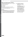
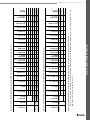
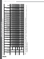
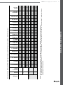
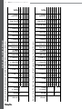
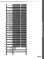
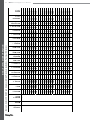
Weld Procedure Guideline Worksheets . . . . . . . . . .
54
3
4
M200 Power Supply User’s Manual
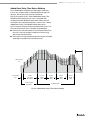
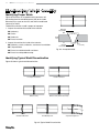
Advanced Weld Procedure Techniques . . . . . . . . . .
64
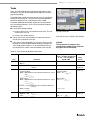
Tacks . . . . . . . . . . . . . . . . . . . . . . . . . . .
65
Ramp Time . . . . . . . . . . . . . . . . . . . . . . . .
66
Ramping Up in Level 1 . . . . . . . . . . . . . . . .
67
Added Rotor Delay Time Before Welding . . . . . . .
69
Step Programs for Multilevel Weld Procedures . . . . . .
71
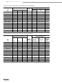
Weld Parameter Guideline
Worksheet Reference Data . . . . . . . . . . . . . . . .
80
Single Level Mode Operation . . . . . . . . . . . . . . . .
84
Single Level Current-Control Group . . . . . . . . . . .
84
Single Level Timing-Control Group . . . . . . . . . . . .
85
Single Level Weld Process Buttons . . . . . . . . . . . .
86
Single Level Status Indicator Lights . . . . . . . . . . .
87
Single Level Weld Status Conditions . . . . . . . . . . .
87
Single Level Weld Procedure Guidelines . . . . . . . . .
88
Evaluating Weld Quality . . . . . . . . . . . . . . . . . . .
96
Identifying Proper Welds . . . . . . . . . . . . . . . . .
96
Identifying Typical Weld Discontinuities . . . . . . . . . .
96
Improper Welds . . . . . . . . . . . . . . . . . . . . . .
97
No ID Penetration . . . . . . . . . . . . . . . . . . .
97
Increased ID Convexity and Weld Bead Width . . . .
98
Weld-Puddle Overlap . . . . . . . . . . . . . . . . .
98
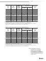
Specifications . . . . . . . . . . . . . . . . . . . . . . . . 100
M200 Power Supply Output and Duty Cycle . . . . . . . 100
M200 Power Supply with 115 V Input . . . . . . . . . 100
M200 Power Supply Cycle Times . . . . . . . . . . . 101
M200 Power Supply Dimensions . . . . . . . . . . . . . 101
Use of Extension Cords
with the M200 Power Supply . . . . . . . . . . . . . . . 101
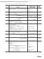
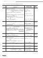
Troubleshooting . . . . . . . . . . . . . . . . . . . . . . . 102
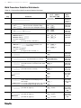
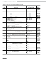
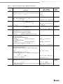
Weld Status Conditions . . . . . . . . . . . . . . . . . . 102
Disable . . . . . . . . . . . . . . . . . . . . . . . . . 102
Operational . . . . . . . . . . . . . . . . . . . . . . 104
Weld Errors . . . . . . . . . . . . . . . . . . . . . . 106
Weld System Hardware and
Weld Process Problems . . . . . . . . . . . . . . . . . . 108
Power Supply Repair . . . . . . . . . . . . . . . . . . . 116
Glossary . . . . . . . . . . . . . . . . . . . . . . . . . . . 118
Swagelok Embedded System
End User License Agreement . . . . . . . . . . . . . . . . 122
The Swagelok Limited Lifetime Warranty . . . . . . . . . 124
M200 Power Supply User’s Manual
Safety
Safety Summary
Arc welding can be hazardous.
Read the entire safety information section and
M200 Power Supply User’s Manual before using
this product. Failure to do so can result in serious
injury or death.
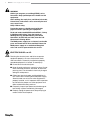
Signal Words and Safety Alert Symbols
Used in this Manual
WARNINGStatements that indicate a hazardous situation
which, if not avoided, could result in death or
serious injury.
CAUTIONStatements that indicate a hazardous situation
which, if not avoided, could result in minor or
moderate injury.
NOTICE Statements that indicate a hazardous situation
which, if not avoided, could result in damage to
the equipment or other property.
afety alert symbol indicating a potential personal injury
S
hazard.
afety alert symbol indicating a potential for personal
S
injury from electrical shock.
afety alert symbol indicating a potential for personal
S
injury from exposure to fumes and gases.
afety alert symbol indicating a potential for personal
S
injury from exposure to the weld arc.
afety alert symbol indicating a potential for personal
S
injury resulting from a welding related fire or explosion.
afety alert symbol indicating a potential for personal
S
injury resulting from a welding related cylinder explosion.
5
6
M200 Power Supply User’s Manual
WARNING
Orbital gas tungsten arc welding (GTAW) can be
hazardous. Only qualified persons should use this
equipment.
After welding, the work piece, weld head, electrode,
fixture block, and collets can be extremely hot and
may cause burns.
Keep children away.
Pacemaker wearers should consult with their
physician before operating this equipment.
Read and understand ANSI Standard Z49.1, “Safety
in Welding and Cutting,” from the American
Welding Society and OSHA Safety and Health
Standards, 29 CFR 1910 and 1926, from the U.S.
Government Printing Office.
The M200 power supply has no internal serviceable
parts and should not be disassembled. Return the
M200 power supply to an authorized Swagelok
sales and service representative for service.
ELECTRIC SHOCK can kill.
Touching live electrical parts and failure to operate
equipment properly can cause fatal electric shock
and severe burns. Incorrectly installed or improperly
grounded equipment is a hazard. To avoid injury:
■ Do not touch live electrical parts.
■Keep all panels and covers securely in place. Do not
touch electrode connector, electrode, or rotor after
pressing start. The electrode is electrically charged
during the weld process.
■Follow local electrical codes and the guidelines in
this manual when installing the M200 power supply.
Shock hazards can exist even when equipment is
properly installed, so it is important that the operator
be trained in the proper use of the equipment and
follow established safety practices.
■Frequently inspect input power cord for damage or
bare wiring—replace immediately if damaged.
■Properly unplug the power cord. Grasp the plug to
remove it from the receptacle.
M200 Power Supply User’s Manual
FUMES AND GASES can be hazardous.
Welding produces fumes and gases. Breathing these
fumes and gases may be hazardous to your health.
Build-up of gases can displace oxygen and cause injury
or death. To avoid injury:
■ Do not breathe fumes or gases.
■Ventilate the area and/or use exhaust at the arc to
remove welding fumes and gases.
■When welding materials that produce toxic fumes,
such as galvanized steel, lead, cadmium-plated
steel or other coated metals (unless the coating is
removed from the weld area), or any other welding
material, keep exposure below threshold limit
values (TLV), permissible exposure limits (PEL),
or other applicable health and safety limitation. If
necessary, wear a respirator. Read and understand
the Material Safety Data Sheets (MSDS) and
follow the manufacturer’s instructions for metals,
consumables, coatings, cleaners, degreasers, or
any other substance that may be present during the
weld process.
■Do not work in a confined space unless it is well
ventilated or you are wearing an air-supplied
respirator. Always have a trained watch‑person
nearby. Welding fumes and gases can displace air
and lower the oxygen level causing injury or death.
Be sure the breathing air is safe.
■Do not weld in locations near degreasing, cleaning,
or spraying operations. The heat and rays of the
arc can react with vapors to form highly toxic and
irritating gases.
■The ultraviolet light emitted by the welding arc
acts on the oxygen in the surrounding atmosphere
to produce ozone. Test results➀, based upon
present sampling methods, indicate the average
concentration of ozone generated in GTAW process
does not constitute a hazard under conditions of
good ventilation and welding practice.
■ Shut off gas supply when not in use.
➀ Welding Handbook, Vol 2, 8th ed., American Welding Society.
7
8
M200 Power Supply User’s Manual
ARC RAYS can burn eyes.
Arc rays from the welding process produce intense
visible and invisible (ultraviolet and infrared) rays that
can burn eyes. The M200 power supply is meant for
use only with enclosed Swagelok weld heads, which
minimize exposure to these harmful rays. To avoid
injury:
■ Do not look at welding arc.
■Use protective screens or barriers to protect others
from flash and glare; warn others not to watch the
arc.
■Wear personal protective equipment, including eye
protection.
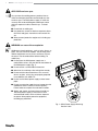
WELDING can cause fire or explosion.
Welding on closed containers, such as tanks, drums, or
pipes, can cause them to explode. The hot work piece
and hot equipment can cause fires and burns. Ensure
the area is free of combustibles before welding. To
avoid injury:
■Do not place the M200 power supply over a
combustible surface. See the label on the bottom of
the M200 power supply (Fig. 1).
■Do not weld in a combustible environment.
■ Watch for fire, and keep a fire extinguisher nearby.
■Do not weld on closed containers such as tanks,
drums, or pipes, unless they are properly prepared
in accordance with AWS F4.1.
■Do not use the M200 power supply to thaw frozen
pipes.
■Do not use extension cords that are in poor physical
condition or have insufficient current capacity.
Failure to do so can pose fire and shock hazards.
■Sparks and spatter are thrown from the weld arc.
The M200 power supply is meant for use with
enclosed weld heads, which minimizes exposure
to spatter. Wear proper protective equipment,
including eye protection.
Fig. 1—M200 Power Supply Mounting
Caution Label
M200 Power Supply User’s Manual
CYLINDERS may explode if damaged.
Gas cylinders used as part of the orbital GTAW process
contain gas under high pressure. If damaged, a cylinder
can explode. To avoid injury:
■Protect compressed gas cylinders from excessive
heat, mechanical shocks, slag, open flames, sparks,
and arcs. Follow all site safety precautions and
protocol.
■Install cylinders in an upright position by securing
to a stationary support or cylinder rack to prevent
falling or tipping.
■Keep cylinders away from any welding or other
electrical circuits.
■Never weld on a pressurized cylinder—explosion will
result.
■Use only correct shielding gas cylinders, regulators,
hoses, and fittings designed for the specific
application; maintain them and associated parts in
good condition.
■Keep head and face away from valve outlet when
opening cylinder valve.
■Keep valve protective cap in place over valve except
when cylinder is in use or connected for use.
■Read and follow instructions on compressed
gas cylinders, associated equipment, and CGA
publication P-1 listed in Referenced Documents,
page 11.
9
10
M200 Power Supply User’s Manual
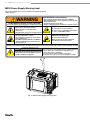
M200 Power Supply Warning Label
This warning label must remain affixed to the top of the power
supply (Fig. 2).
WARNING
Do Not Remove, Destroy, or Cover This Label
For user information contact Swagelok Co. (www.Swagelok.com)
ELECTRIC SHOCK can kill.
• Do not touch live electrical parts.
• Electrode and rotor are live during
weld cycle.
• Keep all panels and covers securely in place.
FUMES AND GASES can be hazardous.
• Do not breathe fumes or gases.
• Use ventilation or exhaust to remove fumes
from breathing zone.
• Read Material Safety Data Sheets (MSDS’s)
and follow manufacturer’s instructions for
the material used.
ARC WELDING can be hazardous.
• Read and follow this label and the User’s Manual.
• Only qualified persons are to install and operate this unit.
• Keep children away.
• Pacemaker wearers keep away.
• Return to authorized sales and service center for service.
WELDING can cause fire or explosion.
• Do not weld on closed containers.
• Do not use in a combustible environment
or over a combustible surface.
ARC RAYS can burn eyes.
• Do not look at welding arc.
• Wear personal protective equipment
including eye and ear protection.
AVERTISSEMENT
LE SOUDAGE A L’ARC peut être dangereux.
• Lisez et respectez cette étiquette ainsi que le manuel utilisateur.
UN CHOC ELECTRIQUE peut être mortel. • Ne pas utiliser dans un environment combustible ou au
• Seules des personnes qualifiées peuvent
installer et utiliser cet appareil.
dessus d'une surface combustible.
• Ne touchez pas les parties électriques sous tension.
• L'électrode et le rotor sont sous tension pendant le soudage.
Fig. 2—M200 Power Supply Warning Label
SWS-M200-LBL-WARN-E
Read American National Standard Z49.1, “Safety in Welding and Cutting,” from American Welding Society, 550 N.W. LeJeune Rd., Miami, FL 33126;
OSHA Safety and Health Standards, 29 CFR 1910 and 1926, from U.S. Government Printing Office, P.O. Box 371954, Pittsburgh, PA 15250
M200 Power Supply User’s Manual
Referenced Documents
1. AWS F4.1, Recommended Safe Practices for the
Preparation for Welding and Cutting of Containers and
Piping.
American Welding Society, 550 N.W. LeJeune Rd, Miami, FL
33126 (www.aws.org).
2. ANSI Z49.1, Safety in Welding Cutting, and Allied
Processes.
American Welding Society, 550 N.W. LeJeune Rd, Miami, FL
33126 (www.aws.org).
3. CGA Publication P-1, Safe Handling of Compressed Gases
in Cylinders.
Compressed Gas Association, 4221 Walney Road, 5th Floor,
Chantilly VA 20151-2923, (www.cganet.com).
4. OSHA 29CFR 1910 Subpart Q, Welding Cutting, and
Brazing.
Acquire from U.S. Government Printing Office,
Superintendent of Documents, P.O. Box 371954, Pittsburgh,
PA 15250 (www.osha.gov).
5. OSHA 29CFR 1926 Subpart J, Welding and Cutting.
Acquire from U.S. Government Printing Office,
Superintendent of Documents, P.O. Box 371954, Pittsburgh,
PA 15250 (www.osha.gov).
11
12
M200 Power Supply User’s Manual
M200 Power Supply User’s Manual
Installation and Setup
13
14
M200 Power Supply User’s Manual
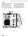
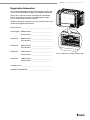
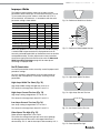
Description
The Swagelok Welding System M200 power supply
provides precise control of weld current, electrode
travel speed, and OD shield gas flow to produce
consistent and repeatable weld results.
The unit features a touch-screen display for easy
navigation and data input. To access menus and
input weld data, the operator presses the touch
screen over the selection. In the Single Level Mode,
users can enter data using simulated thumb wheels.
Four USB A version 1.1 ports on the side of the M200
power supply accept compatible USB hardware,
such as a USB mouse or keyboard, with no additional
software required. A USB flash drive (not supplied)
provides portable memory and can be used to
transfer data to other M200 power supply units and/
or a PC. A 1 GB USB flash drive is recommended.
There are additional ports for video SVGA output and
a serial cable for direct PC connection.
On/off switch
4 USB A 1.1 ports
Power cord
connection
Touch screen
Speaker
Video (SVGA) out
connection
Serial output
connection
Fan housing
Fig. 3—M200 Power Supply Left Side
Nonslip feet
M200 Power Supply User’s Manual
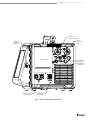
15
Electrode
connection (red)
Work
connection
(green)
Remote
pendant
connection
Printer housing
Auxiliary output
connections
Weld head
connection
Fig. 4—M200 Power Supply Right Side
ID shield gas
connections
OD shield gas
connections
16
M200 Power Supply User’s Manual
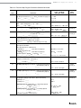
Unpacking the M200 Power Supply
Table 1—Shipping Case Contents
Description
M200 power supply
Ordering Number
SWS-M200-XX-Y
Qty
1
-X X denotes power cord
plug type
-Y denotes user’s manual
language
Power cord
SWS-M200-CORD-XX
Note: Contact your authorized Swagelok
representative if the unit is damaged.
1
-X X denotes power cord
plug type
1/4 in. male
Quick-Connect stem
SS-QC4-S-400
1
M200 Power Supply
User’s Manual
MS-13-212-Y
1
Warranty Information Form
-Y denotes user’s manual
language other than English
—
1
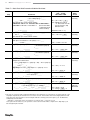
Remove the contents of the shipping case (Table 1):
1. U
se the handle on the top of the M200 power supply to lift it
out of the case. Place the M200 power supply upright on a
stable surface.
2. Check the M200 power supply and accessories for damage.
3. Record the model number and serial number from the
rating label on the back of the M200 power supply (Fig. 5),
along with the delivery date, on the M200 Power Supply
Warranty Information form and the Registration Information
form, page 17. Return the Warranty Information form to your
authorized Swagelok representative to activate the warranty.
Note: D
o not store the M200 power
supply near corrosive materials.
Store indoors and cover when not
in use.
M200 Power Supply User’s Manual
17
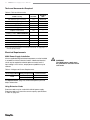
Registration Information
Your authorized Swagelok representative provides support and
service for your M200 power supply and Swagelok weld heads.
Please take a moment to fill out the information listed below.
See the rating label on the back of the M200 power supply.
(Fig. 5) for the model and serial numbers.
Keep this information available in case you need to contact your
authorized Swagelok representative.
Date of Delivery: __________________________________________
Power Supply Model Number: _____________________________
Serial Number: _ ____________________________
Weld Head
Model Number: _____________________________
Serial Number: _ ____________________________
Weld Head
Model Number: _____________________________
Serial Number: _ ____________________________
Weld Head
Model Number: _____________________________
Serial Number: _ ____________________________
Weld Head
Model Number: _____________________________
Serial Number: _ ____________________________
Company Name: __________________________________________
Swagelok Distributorship: __________________________________
Fig. 5—M200 Power Supply Rating Label
18
M200 Power Supply User’s Manual
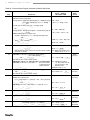
Tools and Accessories Required
Table 2—Tools and Accessories
Tool/Accessory
Hex wrenches (1/2 to 5/32 in.)
Included-
Provided
With
Yes
Weld head
Electrode package
Yes➀
Weld head
Arc gap gauge
Yes➀
Weld head
Flat-blade screw driver
Centering gauge
Yes
Weld head
Yes➀
Fixture block
Calipers or micrometer
No
—
Purge kit
(Ordering number: SWS-PURGE-KIT)
No
—
Low-moisture gas lines
No
—
Gas source
No
—
Pressure regulator
No
—
ID purge gas flow meter
No
—
Pressure gauge
No
—
➀The Series 40 weld head does not include an electrode, arc gap gauge, or
centering gauge package.
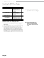
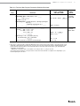
Electrical Requirements
M200 Power Supply Installation
All user-supplied wiring and related components must be installed
in accordance with local electrical codes. A dedicated electrical
circuit may be required to maintain optimum current levels. If
input voltage is 100 V or less, output power capabilities may be
reduced.
Table 3—Voltage and Current Requirements
Power Supply Model Voltage Requirement
M200
Service Current
100 V (ac)
20 A
230 V (ac)
16 A
See Specifications, page 100, for detailed power input and
output information.
Using Extension Cords
Extension cords may be used with the M200 power supply.
Extension cords must meet the current capacity specifications
in Table 43, page 101.
WARNING
The M200 power supply must
be grounded or electrical shock
can result.
M200 Power Supply User’s Manual
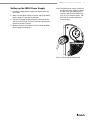
Setting up the M200 Power Supply
1. Position the M200 power supply so that both sides are
accessible.
2. Make sure the power switch on the left side of the M200
power supply is in the off ( O ) position.
3. Connect the power cord to the power connector on the
side of the unit (Fig. 6). Turn the connector a quarter-turn
clockwise to lock it in place.
19
Note: T
he M200 power supply should not
be operated when resting on either
the left or the right side (printer or
fan/filter side) or when tilted more
than 15° on its horizontal axis. The
MFC will not function properly in
these positions.
4. Optional: Install the fan filter on the left side of the M200
power supply. See page 51.
Fig. 6—Connecting the Power Cord
20
M200 Power Supply User’s Manual
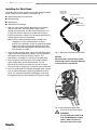
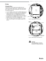
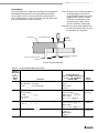
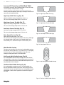
Installing the Weld Head
The weld head assembly attaches to the right side of the M200
power supply with four separate connectors (Fig. 7) :
Weld head
quarter-turn
connector
■ Weld head quarter-turn connector
Electrode (red)
Work (green)
■ Electrode (red)
■ Work (green)
Weld head
OD shield gas
■ Weld head OD shield gas.
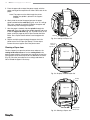
1. A
lign the notch on the weld head quarter-turn connector
with the small tab in the M200 power supply socket
labeled weld head (Fig. 8) and insert the connector. Turn
it clockwise to lock it in place. An audible click indicates
that the connection is locked. This connection provides the
control signals to drive the weld head.
Note: Use the weld head adapter cable included in the
shipping case if the weld head does not have a
quarter-turn connection. Attach the weld head adapter
cable to the end of the threaded multipin connector.
Tighten the weld head adapter cable until only two or
three threads are visible.
2. Insert the red connector arrow side up into the M200 power
supply red socket labeled electrode. Turn the connector
one-quarter turn clockwise to lock it in place. This
connection is the negative (–) terminal of the weld head.
3. Insert the green connector arrow side up into the M200
power supply green socket labeled work. Turn the
connector one-quarter turn clockwise to lock it in place.
This connection is the positive (+) terminal of the weld head.
Fig. 7—Weld Head Assembly Connections
NOTICE
All connections must be fully seated
and locked in place to prevent damage
to connections or weld head.
4. Insert the weld head OD shield gas Swagelok quick-connect
stem into the M200 power supply fitting labeled to weld
head. This connection provides shielding gas to the weld
head through the mass flow controller in the power supply.
Fig. 8—Connecting the Weld Head
Assembly to the Power Supply
ARNING
W
Do not remove the weld head
from the M200 power supply
while a weld is in process.
Electrical shock can result.
M200 Power Supply User’s Manual
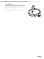
21
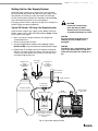
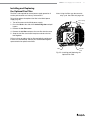
Setting Up the Gas Supply System
The M200 power supply has an integral mass flow controller
(MFC) to control and monitor the flow of the gas supply system
that provides OD shield gas to the weld head. OD shield gas
fills the weld chamber to protect the electrode and weld puddle
from contaminating elements in the surrounding air.
ID purge gas flows within a tube or at the back of a weld joint to
remove oxygen and prevent oxidation.
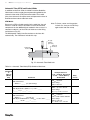
Typical OD Shield / ID Purge Gas Supply System
Figure 9 shows a typical gas supply system. Before setting up
the gas supply system, read and understand the Safety section
of this manual. See page 5.
1. Make sure the gas storage containers are upright and
secured before use.
2. Check all connections for leaks.
3. Use only Swagelok quick-connect stems (ordering number
SS‑QC4‑S‑400) as gas connectors on the M200 power supply.
4. Regulate the OD shield gas pressure to obtain the desired
flow rate. The typical pressure range is 45 to 50 psig (3.1 to
3.4 bar). Flow rates greater than 70 std ft3/h (33 std L/min)
may require higher pressures.
High-pressure
gauge
(0 to 3000 psig
[206 bar])
Two-stage
regulator
CAUTION
Do not mix or interchange
parts with those of other
manufacturers. Personal injury
or equipment damage can result.
NOTICE
Do not exceed an inlet pressure of
100 psig (6.8 bar) or MFC can be
damaged.
NOTICE
The MFC is not a shutoff device. There
may be gas flow of up to 1/2 std ft3/h
(0.24 std L/min) when the shield gas is
off.
Low-pressure
gauge
(0 to 100 psig
[6.8 bar])
Flow meter for
ID purge gas
Supply manifold
ID purge gas
shutoff valve
Inert gas cylinder
Tubing to be welded
M200
power supply
Fixture block
Purge fittings
(Swagelok union or reducing
union with nylon ferrules or
ultra-torr fitting. See Table 2
for purge kit ordering
number.)
Fig. 9—Typical Gas Supply System
OD shield gas
supply inlet
22
M200 Power Supply User’s Manual
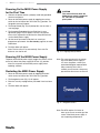
Powering On the M200 Power Supply
for the First Time
1. Connect the power cord to a properly rated and grounded
electrical receptacle.
2. Power on the M200 power supply by toggling the on/off
switch on the left side of the unit to the on ( I ) position. The
Swagelok screen will appear.
CAUTION
The rotor will move when the
M200 power supply is powered
on. The rotor is a potential
pinch point.
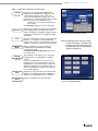
3. The Setup Wizard (Fig. 10) will prompt the user to select a
user language.
4. The Swagelok Embedded System End User License
Agreement (page 122) will appear. You must accept the
terms of this agreement to continue the Setup Wizard and
use the M200 power supply.
5. Set the owner password. If desired, set security or
programmer passwords. See Passwords, page 46, for more
information.
6. The Main Menu will appear.
Note: The fan will turn on automatically. Press the Fan
button to turn the fan off.
Fig. 10—Language Setup Wizard
Powering Off the M200 Power Supply
To power off the M200 power supply, toggle the on/off switch
on the left side of the power supply to the off ( O ) position.
Note: Do not power off the M200 power supply when
updating software.
Restarting the M200 Power Supply
Note: The owner password is the master
key to the M200 power supply. If
it is lost or forgotten, contact your
authorized Swagelok representative.
After ownership of the unit is
verified, you will receive a temporary
password to allow access to the unit.
1. Power on the M200 power supply by toggling the on/off
switch on the left side of the unit to the on ( I ) position.
2. The Swagelok screen (Fig. 11) will appear.
3. Enter the security or programmer password if one has been
set.
4. The Main Menu will appear.
Fig. 11—Swagelok Screen
Note: The MFC requires 5 minutes to
warm up to ensure accurate gas flow
control if the M200 power supply is
not at operating temperature.
M200 Power Supply User’s Manual
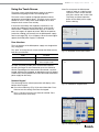
Using the Touch Screen
The touch screen of the M200 power supply is the built-in
method for navigating functions and entering data.
The touch screen responds to fingertip operation and was
designed to accommodate gloves. The touch screen may be
difficult to use if it is dirty or has water droplets on its face.
Keep the touch screen clean and dry.
Note: D
o not expose the M200 power
supply to water or visible moisture.
The touch screen can be cleaned
with glass cleaner and a clean cloth.
To prevent accidental operation,
power off the M200 power supply
before cleaning.
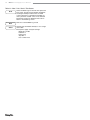
If the touch screen does not respond as expected, it may
need to be calibrated. From the Main Menu, select Setup >
Touchscreen > Calibrate Touchscreen (Fig. 12). A series of
cross hair targets will appear onscreen. While in the position
(seated or standing) you normally use the M200 power supply,
touch each target (Fig. 13) as it appears. When no more targets
appear, the M200 power supply is calibrated.
User Interface
The user interface of the M200 power supply was designed for
easy navigation.
The “path” at the top of each screen (except the Weld screens)
indicates your location:
Path
Fig. 12—Calibrate Touchscreen Button
Location
Main > Setup
Setup mode
Main > Program > Auto Create
Auto Create function
in the Program mode
To select a function or mode, press the onscreen button or
tab with your finger. To enter information, press the field to be
filled in. Depending on the information to be entered, a numeric
keypad, alphanumeric keyboard, or drop-down menu will appear.
A USB mouse and keyboard also can be connected to the M200
power supply for data entry.
Numeric Keypad
The valid range for the selected parameter will display at the
bottom of the keypad.
23
Fig. 13—Calibration Target Screen
■ Press the number keys (Fig. 14) to enter information. Press
Done to save the settings and close the keypad.
■ Press <- Bksp to erase the last character entered. Press
Clear to erase the entire entry.
Fig. 14—Numeric Keypad
M200 Power Supply User’s Manual
24
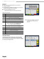
Keyboard
■ Use the onscreen keyboard (Fig. 15) as you would a
computer keyboard.
■ To reposition the keyboard, press the gray bar at the top of
keyboard and drag it to the new position.
■ To close the keyboard, press return.
Note: The return key will not start a new line of text.
Table 4—Key Functions
Key
Function
Home
Moves cursor to the beginning of the line.
End
Moves cursor to the end of the line.
Prop
Moves cursor to the end of the line.
BS
Backspace. Deletes character to the left of the cursor.
Also deletes selections that have been highlighted.
Tab
Closes the keyboard.
return
Closes the keyboard.
Ctrl
Ctrl + z: Undo last step.
Ctrl + x: Cut and save selected/highlighted text.
Ctrl + c: Copy and save elected/highlighted text.
Ctrl + v: Paste saved text at cursor point.
del
Deletes character to right of cursor.
Also deletes selections that have been highlighted.
lt
Moves cursor one space to the left.
rt
Moves cursor one space to the right.
up
Moves cursor to line above.
dn
Moves cursor to line below.
pgup
Moves to the preceding page.
pgdn
Moves to the next page.
Fig. 15—Onscreen Keyboard
Note: To select text, highlight it by pressing
and dragging your finger over the
selection.
Drop-Down Menus
Drop-down menus (Fig. 16) allow you to select entries from
a list. Drop-down menus are indicated by a down arrow (▼).
Press the field or arrow to display the list of selections. Highlight
the selection to change the value.
Fig. 16—Drop-Down Menu
M200 Power Supply User’s Manual
Operation
This section describes the basic operation of the M200 power
supply.
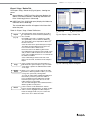
Main Menu
The Main Menu (Fig. 17) provides access to the M200 power
supply’s functions. Select functions by pressing the onscreen
button or by using a USB mouse to click on the selection. The
Main Menu buttons are described in Table 5, page 26.
Fig. 17—Main Menu
25
26
M200 Power Supply User’s Manual
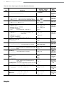
Table 5—Main Menu Selections and Functions
Weld
File
Program
Weld Log
Setup
Next Home
The Weld screens display detailed information
about the weld and are used to input parameters,
start the weld, and monitor the weld process.
The information displayed on the Weld screens is
saved with the weld procedure.
See page 28 for more information about the Weld
screens.
Note: In any M200 power supply screen
or menu, press Back to return to
the previous screen. Press Refresh
to reload and update the current
screen.
The File screens are used to print, preview, delete,
load, and save weld procedures. The File mode
applies only to weld procedures and does not affect
the M200 power supply Setup or Weld Log files.
See page 35 for more information about the File
screens.
The Program screens are used to create new weld
procedures using Auto Create or Manual Create.
See page 38 for more information about the
Program screens.
The Weld Log screens are similar to the File
screens but are exclusively for Weld Log records.
Weld Log records may be viewed, printed, copied,
or deleted using these screens. Weld Log records
may be saved to a USB flash drive for transfer to
a PC. Weld Log records may also be exported to a
PC using a serial cable.
See page 39 for more information about the Weld
Log screens.
The Setup screens are used to change options,
set dimensional units and passwords, and review
settings. Changes are saved in the M200 power
supply’s internal memory and are not part of a weld
procedure.
The Setup mode also contains utilities for updating
software, resetting weld counts, and monitoring
free memory.
See page 42 for more information about the Setup
screens.
CAUTION
The rotor will move when Next
Home is pressed. The rotor is a
potential pinch point.
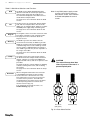
When a Swagelok weld head is first connected
to the M200 power supply, the power supply
assumes the rotor is at true home. If it is not,
press Next Home to move the rotor to the next
of several “home” positions. The weld head
model determines the number of home positions.
Continue pressing Next Home until the rotor
reaches true home (Fig. 18.)
If the weld head cannot find true home, see
Troubleshooting, page 109.
True home
(fully open)
Not true home
Fig. 18—Rotor Home Position
M200 Power Supply User’s Manual
27
Table 5—Main Menu Selections and Functions
Lock Out
(Fig. 19)
Paper Feed
Fan
Single Level
Mode
Language
(Fig. 20)
Help
About
Pressing Lock Out will lock the M200 power
supply. Once the M200 power supply is locked
out, pressing any button on the screen will
cause a password prompt to appear. The owner,
programmer, or security password must be entered.
Note: This feature is not available unless a
programmer or security password has been
set in Setup.
See Passwords, page 46, for more information.
The printer is located on the right side of the M200
power supply, above the weld head connection.
Paper Feed advances the paper through the printer.
See page 45 for information on changing the paper
feed length.
The fan is normally in the Fan Power-On State and
will turn on as needed to cool the M200 power
supply. To turn the fan on manually, press Fan. The
fan will run continuously until Fan is pressed again.
Single Level Mode is for users who prefer
the Swagelok D75 and D100 power supply
programming format.
See Single Level Mode Operation, page 84, for
more information.
Fig. 19—Password Prompt Screen
Note: C
hanging the Fan Power-On State
to off on the Setup > Operation tab
will prevent the fan from turning on
automatically when the M200 power
supply is powered on.
The Language screen allows you to change the
language shown on the M200 power supply’s
screens.
Press the Language button to select the new
language. As soon as the language is selected,
the Back button at the bottom of the screen will
display that language. Press the Back button to
return to the Main Menu, and the screen will be in
the selected language.
Displays the user’s manual. The user manual will
display in the language selected if available. The
English version will display if it is not available.
Displays copyright and patent information.
Fig. 20—Language Screen
28
M200 Power Supply User’s Manual
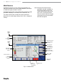
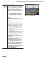
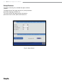
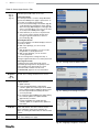
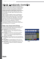
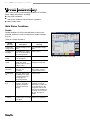
Weld Screens
The Weld screens (Fig. 21) are used to view and adjust (see
Note) the parameters of the active weld procedure. The screen
is divided into upper and lower sections.
The Upper Section Tabs contain information related to the weld
procedure and options: user fields, limits / tolerances, etc.
The Lower Section Tabs are fields that make up the basic
parameters of a weld: purge settings, levels, tacks, and general
settings.
Note: C
hanging the weld procedure
parameters will add “(modified)” to
the weld procedure name on the
screen and cause the name to turn
red in color. The weld procedure
must be saved to make the changes
a permanent part of the procedure.
See Table 9, page 36.
Upper
section
tabs
Weld
procedure
name
Electrode position
Lower
section
tabs
Used to change
electrode
Test the active
procedure (no
current applied)
Jogs electrode
clockwise
Jogs electrode
counterclockwise
OD shield
gas visual
gauge
Turns on OD
shield gas
Status indicator
Timeremaining
counter
Weld head
installed
Weld
procedure
parameters
Fig. 21—Weld Screens
Weld count
M200 Power Supply User’s Manual
29
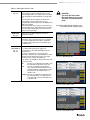
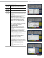
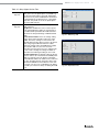
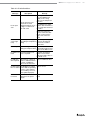
Table 6—Weld Upper Section Tabs
Information
(Fig. 21)
Weld Setup
(Fig. 22)
Notes
Displays a summary of weld setup parameters as
well as ID purge and OD shield gas types for the
active weld procedure. The eight most recent entries
for the Programmer field will display in a drop‑down
box.
The Information tab also displays the Electrode
Change button, which positions the rotor for
electrode replacement and prevents the M200 power
supply from welding.
See the weld head user’s manual for instructions on
electrode replacement. After replacing the electrode,
press Electrode Change again. The rotor will move
back to the home position.
CAUTION
The rotor will move when
Electrode Change is pressed.
The rotor is a potential pinch
point.
Note: E
lectrode Change disables most
other M200 power supply buttons.
Displays the Joint and Setup fields and allows
adjustment of values.
Displays an open field for entering comments and
observations. Press the white area once to display
the onscreen keyboard. Notes will be saved with
the weld procedure and shown in the Weld Log as
Procedure Notes.
User Fields 1 Displays User Fields 1 and 2.
User Fields 2 The software will remember the eight most
recent entries for each field and display them in a
(Fig. 23,
drop‑down box.
Fig. 24)
The owner or programmer can set data entry
requirements that must be completed before a weld
is performed. This information is part of the weld
procedure and is stored in the Weld Log.
Three options are available in drop-down boxes next
to each user field:
NoAn entry is not required for this field. It may
be entered at the discretion of the user.
YesAn entry is required for the field. The
entry will remain in that field until a new
weld procedure is loaded. Failure to enter
information into this field will cause a
disable code.
ChangeAn entry is required in the field and must
be reentered with every weld. Failure to
enter information into this field will cause
a disable code.
Fig. 22—Weld Setup Tab
Fig. 23—User Fields 1 Tab
Fig. 24—User Fields 2 Tab
30
M200 Power Supply User’s Manual
Table 6—Weld Upper Section Tabs
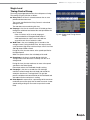
Limits /
Tolerances
(Fig. 25)
Limits
Limits are used to restrict the amount of adjustment
a user with a security password can make without
entering a programmer or owner password.
Limits from 0 to 100 % are set at the programmer
and owner levels. Current and Purge Limits are
represented as a percentage of the weld procedure
values.
Example: if the Average Amps for Level 1 is
100 A and the current limit is 50 %, the M200
power supply will not allow an adjustment of
Average Amps above 150 A or below 50 A. The
factory default for limits is 100 %.
Average Amps can be adjusted within the limits on
the lower section Levels tab using the up and down
buttons.
See Adjusting Average Amps, page 31, for more
information.
Purge parameters can be adjusted within the limits
on the Purge Setup tab.
Tolerances
The Weld Log records out-of-range values for
Average Amps, Average Speed, and OD Shield Flow
in the Weld Log, based on tolerances set. Tolerances
are adjustable at the programmer and owner levels,
as a percentage of the base value.
■ Current and speed tolerances are adjustable
up to 9.9 %. The factory default for new weld
procedures is 2.5 %.
■ Purge tolerance is adjustable up to 100 %. The
factory default is 15 %.
Example: if the Average Amps for Level 1 is
100 A and the current tolerance is 5 %, the M200
power supply will return a current tolerance error
at the end of the weld if the Average Amps is
below 95 A or exceeds 105 A.
Current tolerance. If the Average Amps tolerance is
exceeded during the weld, a current tolerance error
will be recorded.
Speed tolerance. If the average speed is outside of
the average speed tolerance at the end of the weld,
a speed tolerance error will be recorded.
Purge tolerance. Purge tolerance is represented
by the yellow band in the shield gas flow meter
displayed on the process tab. If the OD shield flow
is outside of the tolerance, the shield gas bar flow
meter display will turn red. If there is no OD shield
gas present during prepurge, the M200 power
supply will not proceed. If the OD shield gas flow
drops below 8 std ft3/h (3.8 std L/min) during a weld,
the M200 power supply will stop welding to prevent
possible damage to the weld head.
See page 106, Weld Errors.
Fig. 25—Limits / Tolerances Tab
M200 Power Supply User’s Manual
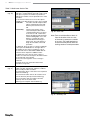
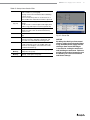
Table 7—Weld Lower Section Tabs
Process
(Fig. 26)
Purge Setup
(Fig. 27)
General
(Fig. 28)
Levels (X)
(Fig. 29)
Displays the status and progress of the weld,
including tacks, error messages and electrode
position.
Displays the Normal Purge, Blast Purge, and Gas
Type fields.
Displays the Start and Finish fields.
A level is a section of the weld procedure defined by
the parameters shown in Fig. 29. Parameters can be
varied by level.
A weld procedure can have from 1 to 99 levels. The
number in parentheses indicates the number of
levels specified in that weld procedure.
Levels are shown in the process window in real time
during the weld. To add a level, press the top of a
column to highlight it, then press the Add button
on the right side of the window. A new column
containing a copy of the selected column’s data
will be added after the selected column. Repeat for
additional levels.
To delete one or more levels, press the top of the
column or columns to select them. Press the Delete
button on the right side of the window.
Adjusting Average Amps
Adjust Up / Down allows a user with a security
password to make Average Amps adjustments
within the limits and tolerances set by the owner or
programmer.
Select the level or levels to be adjusted and press
the up or down buttons to adjust Average Amps
(page 30) within the limits in a weld procedure
defined by the programmer. If no level is selected, all
levels are affected by Adjust Up / Down.
Average Amps is reduced with the down button or
increased with the up button.
■ The first three presses of the up or down button
increase or decrease High Amps Width in
increments of 10 %, up to 30 %.
■ The next three presses of the up or down button
increase or decrease High Amps in increments
of 10 %, up to 30 %.
■ The final three presses of the up or down button
increase or decrease Low Amps in increments of
10 %, up to 30 %.
To return to the original values for the weld
procedure you must reload the program from
memory.
See Limits / Tolerances, page 30, for more
information.
Fig. 26—Process Tab
Fig. 27—Purge Setup Tab
Fig. 28—General Setup Tab
Fig. 29—Levels Tab
31
32
M200 Power Supply User’s Manual
Table 7—Weld Lower Section Tabs
Tacks (X)
(Fig. 30)
Summary
(Fig. 31)
The M200 power supply supports weld procedures
with tacks—nonpenetrating spot welds used to hold
work pieces in place. The number in parentheses
indicates the number of tacks specified for the weld
procedure.
To set the tack method, choose from the options
available in the drop-down box next to the user field:
AutomaticThe entire selected weld procedure
will be completed when the Start
button is pressed on the Process
tab.
Tacks OnlyOnly the tacks portion of the
selected weld procedure will be
completed. When the user returns
to the Process tab, a Start Tacks
button will appear under the Weld
Head Installed graphic. Press this
button to complete the tacks.
The Start button will change to
Start Levels. Press this button to
begin the remainder of the weld
procedure.
To add tacks, press the top of a column to highlight
it, then press the Add button on the right side of
the window. A new column containing a copy of
the selected column’s data will be added after the
selected column. Repeat for additional tacks.
To delete tacks, press the top of the column or
columns to select them, then press the Delete button
on the right side of the window.
Use the onscreen keypad to enter or change a
parameter.
See page 65 for more information about weld
procedures using tacks.
Fig. 30—Tacks Tab
Note: Tacks should be offset at least 10°
from the location of the arc start
of the levels to prevent arc wander
at arc start. The weld head returns
to the true home position after the
tacking section of a weld procedure.
This tab provides information on the M200 power
supply’s Disable, Operational, and Error conditions
when a weld procedure is loaded.
The View button allows a look at the last completed
weld in the Weld Log.
The Clear Errors button remove all nonactive errors
from the Summary View (but not the Weld Log.)
Choose the Active Only check box to limit the
Summary View to the active weld.
Weld Log notes will print with the Weld Log.
Fig. 31—Summary Tab
M200 Power Supply User’s Manual
Table 8—Weld Screen Buttons
Test
Jog
Jog Back
Shield Gas
Start
Home
Print
Stop
Check or demonstrate a weld procedure with
this mode. Press to put the power supply in an
alternate operating mode that will not supply
current to the electrode. Press again to stop. The
current and voltage displays will not operate and
the weld counter will not advance. The light in
the corner of the button will blink while the power
supply is in Test mode.
Press to move rotor clockwise. Press again to stop.
The light in the corner of the button will blink while
the rotor is moving.
Press to move rotor counterclockwise. Press again
to stop. The light in the corner of the button will
blink while the rotor is moving.
Activates the mass flow controller and starts the
flow of OD shield gas to the weld head. Shield
gas will flow to the weld head until you press the
button again. Pressing the Shield Gas button does
not override Purge Setup settings in the weld
procedure, but gas will continue to flow after the
weld procedure is complete.
Starts the weld process.
See Performing a Weld, page 34.
Press to return the rotor to its true home position.
The rotor will move at maximum speed when
traveling to the home position, regardless of the
programmed rotor speed.
Prints last completed Weld Log record.
Aborts the weld and halts the rotor if pressed
during the weld process. Stop also turns off OD
shield gas flow.
33
34
M200 Power Supply User’s Manual
Performing a Weld
Read and understand all safety information contained in
this manual before starting the weld.
1. Complete all side panel connections as described in Setting
Up the M200 Power Supply, page 19, Installing the Weld
Head, page 20, and Setting Up the Gas Supply System,
page 21.
WARNING
Do not touch the cable
connectors during the weld. If
the cables have been damaged,
the potential for an electrical
shock exists.
2. Install the electrode and set the arc gap using the arc gap
gauge in accordance with the weld head user’s manual.
3. Install the collets in the fixture block.
4. Align and clamp the work pieces in the fixture block.
5. Load an existing weld procedure as described in Load /
Save / Print / Delete Tab, page 35, or create a new weld
procedure as described in Program, page 38.
6. Connect the ID purge gas line to the work pieces to be
welded and set the flow meter.
7. Connect the weld head to the fixture block.
8. Press the Start button.
Display Indications During Welding
During welding, the status messages are displayed on the
Process tab, along with a time-remaining counter.
After the Weld is Complete
1. The M200 power supply will return to the “Ready” state.
2. Check the fixture block to confirm that it has cooled before
handling. Increasing the postpurge or blast purge postweld
time will aid cooling.
3. Remove the weld head from the fixture block. If it is difficult
to remove, release one of the side plate levers.
4. Remove the ID purge gas lines from the welded assembly.
5. Remove the welded assembly.
Weld Status Conditions
See Troubleshooting, page 102, for a list of disable,
operational, and weld error conditions.
CAUTION
Use gloves or other protective
devices if you must handle parts
immediately after welding. The
parts can be extremely hot and
may cause burns.
NOTICE
Do not immerse the hot fixture block in
water after welding. Allow the fixture
block to cool before performing the
next weld.
Note: Inspect the electrode after each
weld. Look for oxidation, wear, or
weld material on the tip.
M200 Power Supply User’s Manual
35
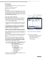
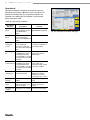
File Screens
The File screens are used to load, save, print, copy, delete, and
view weld procedures.
The Main > File screen has two tabs:
■ Load / Save / Print / Delete
■ File Copy
When the File screen opens, the M200 power supply searches
the internal memory and a connected USB flash drive. A large
number of folders can slow the search process. To reduce the
time required, delete unnecessary files or folders in the internal
memory and on the USB flash drive.
Load / Save / Print / Delete Tab
Selected file (with green icon)
Folder View pane
File View pane
The File screen opens in the Load / Save / Print / Delete tab,
showing Folder and File Views in separate panes (Fig. 32):
■ The Folder View displays folders for the internal memory
and a connected USB flash drive.
■ The File View displays the weld procedures contained in an
open folder. The active weld procedure will have a green
icon.
In the Folder View, press the folder name or icon to open it.
The weld procedures will be displayed in the File View pane
in alphabetical order. The Folder View will also display any
subfolders contained in the original folder.
The buttons on the lower left (Print, View, Delete, and Load)
require you to select a file or folder before you press a button.
Press a weld procedure in the File View pane to highlight it. The
weld procedure name will appear in the File Name box below
the File View pane.
Enter a file name in the File Name box before pressing the Save,
Rename, or Create Folder buttons on the lower right of the
screen.
When a file name is entered and saved, a description that
includes the OD, wall thickness, tubing material, number of
levels, number of tacks, and weld head model will be added
automatically to the file name and displayed in the File View,
and whenever the weld procedure is loaded:
User’s manual example [0.500 - 0.049 316LV 04 03 5H A]
User’s manual example programmer-selected file name
0.500 OD of work piece
0.049 wall thickness of work piece
316LV tubing material
04 number of levels
03 number of tacks
5Hweld head model needed for
weld procedure
A ATW weld procedure
P pipe schedule
S step program
The display will automatically change to the Weld/Process tab
after a Save has been performed.
Status line
File Name box
Fig. 32—Load / Save / Print / Delete Tab
Note: F
ile names are limited to
alphanumeric characters. The M200
power supply software does not
support symbols such as:
, + , – , % , / , ” , ’ , , , or
similar characters.
36
M200 Power Supply User’s Manual
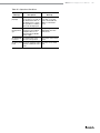
Table 9—Load / Save / Print / Delete Tab Buttons
Print
View
Delete
Load
Save
Rename
Create
Folder
Select the weld procedure in the File View pane
and press Print.
Select the weld procedure from the File View
pane and press View. The file preview window
will appear showing the weld procedure name, a
description, the programmer’s name, and the date
the weld procedure was saved. Joint, Level, and
Tack parameters will also be displayed.
Press OK to return to the File screen.
Select the weld procedure or folder and press
Delete. A dialog box will open asking you to
confirm the delete. Press Yes to delete the weld
procedure or folder.
Select the weld procedure from the File View pane
and press Load. A message in the Status line will
confirm that the weld procedure was successfully
loaded.
Select the folder in which to save the weld
procedure. Press the File Name box. The keyboard
will appear. Enter the name of the new weld
procedure and press Save. The weld procedure will
be saved and displayed in the File View pane.
To rename a weld procedure, select the weld
procedure. The weld procedure name will be
shown in the File Name box. Press Rename and an
input box and a keyboard will be displayed. Enter a
new file name and press Rename in the input box.
Create Folder allows you to create an empty
subfolder in internal memory or on the USB flash
drive.
To create a new subfolder, highlight the folder you
want to put the new subfolder in and select the File
Name box. Enter the name of the new folder using
the keyboard and press Create Folder.
The new subfolder will appear in the Folder View
pane.
Note: F
olders cannot be renamed using
Rename.
M200 Power Supply User’s Manual
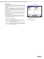
File Copy Tab
Folder panes
The File Copy tab (Fig. 33) allows the user to copy folders and
files between folders in internal memory or to and from a USB
flash drive.
When the File Copy tab opens, the internal memory and USB
Flash Drive (if attached) folders will be shown in both folder
panes. Press a folder twice to display its contents. Press twice
again to close it.
To copy a file, select the destination folder and the file to copy.
Press Copy >> or << Copy. If you select a folder, the entire
folder will be copied.
The Folder Move fields show the name of the folder or file
selected. The Status line at the bottom of the screen displays
status and error messages.
Table 10—File Copy Tab Buttons
Copy >>
<< Copy
Copies the selected folder or file from the left
Folder Move field to the selected destination in the
right Folder Move field.
Copies the selected folder or file from the right
Folder Move field to the selected destination in the
left Folder Move field.
Folder Move fields
Status line
Fig. 33—File Copy Tab
37
38
M200 Power Supply User’s Manual
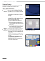
Program Screens
The Program screens (Fig. 34) are used to create new weld
procedures using Auto Create or Manual Create.
Table 11—Program Screen Buttons
Auto Create
(Fig. 35)
Manual
Create
(Fig. 36)
When you select Auto Create, a dialog box will
ask you to confirm overwriting the active weld
procedure. Press Yes to overwrite the active weld
procedure.
The active fields on the Auto Create screen are
shown in black. As these fields are completed, the
inactive fields (in gray) will activate in response to
the entries.
The eight most recent entries for the Programmer
field will display in a drop‑down box.
To change the # Levels and # Tacks entries from
the default, press the field to display the keypad.
Enter your changes and press Done.
The Save Procedure drop-down box has two
options:
■ Active (No - Save) will take you directly to the
Main > Weld screen for immediate use. You
can run the weld procedure and make changes
before saving.
■ Save Procedure will take you to the Main > File
screen. On this screen you can enter a name
for the weld procedure and save it to internal
memory or the external USB flash drive.
Manual Create allows programmers to write their
own weld procedures using the Weld screens.
When you select Manual Create, a dialog box will
open, asking you to confirm overwriting the active
weld procedure. Press Yes to overwrite the active
weld procedure.
The Weld screen will open, with all data cleared,
so that you can enter parameters for a new weld
procedure.
See Weld Parameter Development, page 52,
for more information and worksheets for use in
developing a weld procedure.
The Manual Create screen may also be used to
clear the active weld procedure.
Fig. 34—Program Screen
Fig. 35—Auto Create Screen
Fig. 36—Manual Create Screen
M200 Power Supply User’s Manual
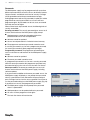
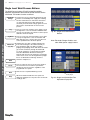
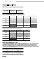
Weld Log Screens
A Weld Log record is saved to internal memory for every
completed weld. This feature cannot be disabled, but Weld Log
records can be deleted after they are saved to internal memory.
The Weld Log records the following data:
Description
Inputs
Outputs
Performance
Confirmation
Weld procedure, with specific settings
Weld level information
Weld results
Operational conditions, errors, notes
The Weld Log screen has two tabs:
■ View / Print / Serial
■ Export / Copy / Delete
The Weld Log screen manages Weld Log records, which are
saved to the Internal Memory\Weld Log folder. Subfolders
cannot be created in the internal memory\Weld Log folder.
Weld Log files can be copied to an external USB flash drive.
Subfolders can be created on the USB flash drive.
After every completed weld, a Weld Log file name is created
automatically in accordance with the following convention:
2007-09-27
2007-09-27
10-56
00012 001251 123456
.xml
10-56 00012 001251 123456.xml
date
time (24 h clock)
weld counter (resettable)
arc start counter (nonresettable)
M200 power supply serial number
file format
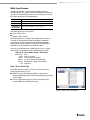
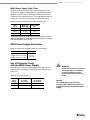
View / Print / Serial Tab
The Weld Log screen opens in the View / Print / Serial tab,
displaying two panes (Fig. 37):
■ Folder View (left pane) displays folders in the Internal
Memory\Weld Log and the USB flash drive\Weld Log (if drive
is connected).
■ File View (right pane) displays the files contained in the
selected folder in the Folder View pane.
Fig. 37—View / Print / Serial Tab
39
40
M200 Power Supply User’s Manual
Table 12—View / Print / Serial / Tab Buttons
View
Print
Serial
Select the Weld Log from the File View pane and
press View. The File Preview window will appear,
showing the weld procedure name, the weld
count, performance confirmation (including any
errors), and time created. Joint, Level, and Tack
parameters will also be displayed. Press OK to
return to the Weld Log screen.
Prints the selected Weld Log record.
Transfers files and folders directly to a PC using a
serial cable.
M200 power supply serial port settings:
Baud rate: 38 400
Data bits: 8
Parity: None
Stop bits: 1
Flow control: None
M200 Power Supply User’s Manual
41
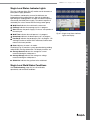
Export / Copy / Delete Tab
The Export / Copy / Delete tab (Fig. 38) opens, showing two
panes:
■ Internal Memory / USB Flash Drive (left pane) displays the
folders in the Internal Memory \ Weld Log and USB Flash
Drive \ Weld Log (if drive is connected).
■ USB_Flash_Drive_ONLY (right pane) displays the folders for
USB Flash Drive \ Weld Log.
The selected folder and files will appear in the Name field
below the pane.
Table 13—Export / Copy / Delete Tab Buttons
Export
(Fig. 39)
Copy
Create
Folder
Delete
The Export button allows the Weld Log record to
be exported from the Internal Memory\Weld Log
into a text file.
Each Weld Log record is a separate line. Fields
are separated by commas within the Weld Log.
The exported file can be imported into Microsoft®
Excel® or Access®.
Select the folder to be exported and press Export.
The Weld Log Export dialog box will open. The
From and To locations will be shown.
Enter a file name in the Weld Log Name field.
Check Append to File if the file name already exists
and you want to add the data to the file. If the file
name exists and Append to File is not selected, the
file will be overwritten.
Select a Date Range, Dimensional Units, Flow
Units, Pressure Units, and Date Format and press
Export.
Select a folder or file from the Internal Memory /
USB Flash Drive pane and press Copy. The folder
or file will be copied to the USB flash drive folder
on the right.
Allows you to create an empty folder in the USB
Flash Drive / Weld Log folders. Folders you create
must go into a previously existing folder.
To create an empty folder, highlight the USB Flash
Drive folder you want to put the new folder in.
Press the Weld Log Name field below the USB
Flash Drive pane. Type in the name of the new
folder and press Create Folder.
The new folder will appear in the USB Flash Drive /
Weld Log folders in both panes.
Folder contents can be deleted from internal
memory and the USB flash drive. To delete a folder
and its contents, highlight the folder and press
Delete. A dialog box will ask you to confirm the
delete. Press Yes to delete the folder.
Name field
Weld Log Name field
Fig. 38—Export / Copy / Delete Tab
Fig. 39—Weld Log Export Dialog Box
42
M200 Power Supply User’s Manual
Setup Screens
The Setup screen (Fig. 40) is divided into upper and lower
sections.
The Upper Section Tabs apply primarily to system parameters:
passwords, language, software, etc.
The Lower Section Tabs apply primarily to hardware
parameters: touch screen, printer, flow control, etc.
Fig. 40—Setup Screen
M200 Power Supply User’s Manual
Table 14—Setup Upper Section Tabs
Weld Log
(Fig. 41)
Specifies the frequency of the Weld Log printout.
When set to zero, the printer prints out a Weld Log
only when the Print button is pressed. Setting Auto
Print Count to any other number defines the interval
at which Weld Logs are printed: set to 1, the printer
prints after every weld; set to 10, the printer prints
after every 10th weld, etc.
Operation
(Fig. 42)
Allows the user to set some of the M200 power
supply functions:
Jog Speed %: Enables the user to set the speed
of the weld head when jogging as a percentage of
the weld head full speed. See the weld head user’s
manual for the full speed ratings of individual weld
heads.
Electrode Touch Volts: This is the voltage setting
used to detect if the electrode touches the weld
puddle. The factory setting of 4 V should not be
adjusted without testing, but may have to be raised
when using longer weld head extension cables.
Raising the voltage makes the M200 power supply
more sensitive and can cause it to record an
electrode touch when there was none and generate
an error code. Lowering the voltage can allow an
electrode touch without generating an error code.
Fan Power-On State: The default setting for the fan
power-on state is on. The first time the M200 power
supply is powered on, the fan button on the Main
screen will blink and the fan will be in the continuous
run state. Changing the Fan Power-On state to off
will make the default for the fan button on the main
screen off. The user can not disable the fan during
the weld cycle. The fan is always on during the weld
cycle.
Fig. 41—Weld Log Tab
Fig. 42—Operation Tab
43
44
M200 Power Supply User’s Manual
Table 14—Setup Upper Section Tabs
Passwords
(Fig. 43 ,
Fig. 44,
Fig. 45)
Shows the current privilege level of the user screen
and allows passwords to be set or reset.
Setting Passwords
The owner password is set in the Setup Wizard the
first time the M200 power supply is powered on. To
set security or programmer passwords:
■ Press the Current Privilege Level button (Fig. 43,
set by default at the Programmer level). A dropdown menu (Fig. 44) will appear on the right side
of the screen that allows you to choose the level
of security for the M200 power supply.
■ Select Owner If you choose to set passwords.
You can now use the Change Security and
Change Programmer buttons to set these
passwords (Fig. 45).
Fig. 43—Current Privilege Level Button
Resetting Passwords
The Current Privilege Level button displays the level
of security in effect:
■ With owner privilege, you can reset any
password.
■ With programmer privilege, you can reset the
programmer or security password.
■ With security privilege, you can reset the
security password.
Press the Change Owner, Change Security, or
Change Programmer buttons to reset the passwords.
Removing Passwords
Programmer and security passwords can be
removed by pressing Enter on the prompt screen
before entering a new password. The owner
password can be reset but not removed.
Fig. 44—Privilege Level Dropdown Menu
See Passwords, page 46, for more information.
Language /
Regional /
Time
(Fig. 46)
Software
Counters /
Statistics
Service
Dimensional units, time and language are set from
this tab. These settings will affect most screens.
Displays the current software version and enables
software updates.
To update software:
■ Insert the USB flash drive containing the
software update into a USB A port on the M200
power supply and press Update Software. Enter
the owner password and carefully follow the
onscreen prompts.
■ Do not power off the M200 power supply during
the software update. The update will take
approximately 5 minutes.
■ Restart the M200 power supply after the
software update is complete for the updates to
take effect.
Fig. 45—Setting or Resetting Passwords
The read-only section keeps track of arc starts,
welds, and misfires. The User Counters section
allows setting the weld counter and gives the
option of counting the weld misfires in with the weld
counter.
Displays the serial number and the last calibration
date of the M200 power supply.
Fig. 46—Language / Regional / Time Tab
M200 Power Supply User’s Manual
45
Table 15—Setup Lower Section Tabs
Touchscreen
Press Calibrate Touchscreen to recalibrate the cursor
position relative to your fingertip.
See page 23 for more information about calibrating
the touch screen.
Press Front Panel Key Click on or off to turn on or
off the audible click heard when a button is pressed.
Printer
(Fig. 47)
Displays Printer status (paper out, head up) and
settings.
Use this screen to set the Paper Feed Length (short,
medium, long) and Paper Cut (manual, partial, full).
Remote
Displays Remote status (connected, type) and
settings. Use this screen to turn the Remote Key
Click on or off.
Weld Head
Displays weld head status (head connected, head
type).
Flow Control Allows disabling of the MFC that controls the OD
shield gas and turns off disable, operational, and
error codes associated with OD shield gas flow.
Sound
Internal
Memory
USB Flash
Memory
Turns the Alarm on or off. When this function is
on and a weld error occurs, the audible alarm will
sound. The error displays on the Status line and is
recorded in the Weld Log.
Displays the status of the system memory (capacity,
used space, free space).
Displays the status of the USB flash drive memory
(capacity, used space, free space).
Fig. 47—Printer Tab
NOTICE
Disabling the shield gas flow control
allows a weld to be performed without
using the M200 power supply internal
shield gas flow control. Shield gas
is essential to cooling the weld head
and shielding the weld zone. Failure to
provide an alternative (external) means
of shielding can result in weld head
and fixture damage.
46
M200 Power Supply User’s Manual
Passwords
The M200 power supply may be programmed with up to three
different password levels to restrict access to different features.
One password is available for each level of security. Privileges
will be granted based on the password entered at login.
Setting programmer and security passwords is optional. If neither
programmer nor security password is set, all users will have
programmer rights. All passwords can be set, reset, or removed
from their own level or higher.
When all three levels of passwords are set, the following levels of
security are enabled:
Security password. The security password gives access to all
features and functions of the M200 power supply except:
■ Weld parameters cannot be changed outside of the
predetermined limits of the weld procedure.
■ Software cannot be updated.
■ Access to weld procedures is limited to internal memory.
■ The programmer and owner passwords cannot be reset.
If a security password is set, but not a programmer password,
the security password will allow programmer privileges.
Programmer password. The programmer password gives
access to all features and functions of the M200 power supply,
except:
■ Software cannot be updated.
■ The owner password cannot be reset.
If a programmer password is set, but not a security password,
either the owner password or the programmer password may
be entered to log in to the unit or to use the Lock Out feature.
Owner password. The owner password gives access to all
features and functions of the M200 power supply, including
software updates.
If any passwords in addition to the owner password are set, the
M200 power supply will display a user prompt for a password
when it is powered on. Enter and confirm the password and
press Privilege Level to view the access granted. Press Enter to
use the password and log in to the M200 power supply (Fig. 48).
If you do not set security and programmer passwords:
■ The M200 power supply will not prompt for a password
when it is powered on.
■ Weld procedures can be updated without a password.
■ All users will have programmer level rights.
■ The Lock Out feature will not function.
Fig. 48—Login Screen
M200 Power Supply User’s Manual
Remote Pendant
The pendant provides remote operation of the primary power
supply controls Start, Stop, Home, and Shield Gas. It also
displays power supply status indicators On, Ready, Weld, and
Error.
ON REA
DY
WELD ERR
OR
STAR T
STOP
HOME
GAS
The pendant is attached to the power supply via a cable and
he connector labeled Remote on the right side of the power
supply. (Fig. 49)
Fig. 49— Remote Pendant
47
48
M200 Power Supply User’s Manual
Maintenance
The M200 power supply has no internal serviceable parts
and should not be disassembled. The only field-replaceable
parts are the printer paper and optional fan filter. Contact
your authorized Swagelok representative for any other service
needs.
WARNING
Do not attempt to service the
M200 power supply. Electrical
shock can result.
M200 Power Supply User’s Manual
Printer
49
Latches
Changing Paper
The printer uses thermal paper rolls available from your
authorized Swagelok representative. Standard thermal paper
rolls available at most office supply stores may also be used.
Printer
cover
To change the paper roll:
1. Press the latches and pull open the printer cover (Fig. 50).
2. If there is still paper in the printer, press the cutting head
release lever to open the cutting head. Remove the
remaining paper. Press the cutting head down to close.
3. Press the ends of the spindle and lift it out of the support
bracket (Fig. 51). Discard the used paper roll.
4. Open a new paper roll and trim the edge so it is straight.
A torn or uneven edge will make loading the paper more
difficult.
Paper slot
Fig. 50—Opening the Printer Cover
Support
bracket
Spindle
Paper roll
Cutting
head
Cutting edge
Cutting head
release lever
Fig. 51—Removing the Used Paper Roll
CAUTION
The cutting edge is sharp. Do
not touch it or injury may result.
50
M200 Power Supply User’s Manual
5. Place the paper roll on top of the power supply, with the
paper coming off the top of the roll. Allow some slack in the
paper.
Paper roll
Note: T
he paper must be fed through the printer
before the spindle is placed in the support
bracket.
6. Gently slide the end of the paper between the paper
guides and behind the metal lip (Fig. 52) as far as it will go.
After a few seconds, the printer will detect the paper and
automatically feed it through the printer.
7. After the paper is loaded, slide the spindle through the
paper roll. Press the ends of the spindle together and snap
it into the support bracket (Fig. 53). To remove slack in the
paper, re-roll the paper or press Paper Feed on the Main
Menu. Press Paper Feed to advance and straighten the
paper.
8. Slip the end of the paper through the paper slot in the
printer cover. Press Paper Cut (Setup > Printer tab) to
remove the excess paper. Close the printer cover.
Clearing a Paper Jam
To clear a paper jam, open the printer cover and press the
cutting head release lever to set the cutting head in the
partially open position. If the paper jam cannot be cleared, the
cutting head can be rotated up to 90° for additional clearance
(Fig. 54). Clear the jam and press the cutting head down to
close. Reload the paper if necessary.
Metal lip
Fig. 52—Loading the Paper Roll
Support
bracket
Spindle
Paper roll
Fig. 53—Properly Loaded Paper Roll
Cutting
head
Paper roll
Cutting head
release lever
Fig. 54—Clearing a Paper Jam
M200 Power Supply User’s Manual
51
Installing and Replacing
the Optional Fan Filter
The filter is not required for normal power supply operation. It
can be purchased for use in dusty environments.
Note: U
sing the filter may decrease the
duty cycle. See Table 39, page 100.
To install or replace the optional fan filter in the M200 power
supply (Fig. 55):
Fan housing
door
Latch
1. Turn off the power to the M200 power supply.
2. Press the latch at the side of the fan housing door and pull
it open.
3. Remove the fan filter cover.
4. Remove the old filter and press the new filter into the cover.
5. Snap the fan filter cover back into place and close the fan
housing door.
ailure to clean or replace the fan filter periodically could result
F
in excessive heat buildup. Contact your authorized Swagelok
representative for replacement filters.
Filter
Fan filter
cover
Fig. 55—Installing and Replacing the
Optional Fan Filter
M200 Power Supply User’s Manual
52
Weld Parameter Development
Weld parameters are the values used to create a weld
procedure. The shape and duration of the output current
waveform—a graphical representation of the weld procedure—
is determined by the weld parameter settings. Figure 56 shows
the waveform typical parameters generate during the course of
a multilevel weld. The weld parameter settings are:
Parameter
1
2
3
4
High Amps, A
71.7
68.1
64.5
60.9
Low Amps, A
21.7
21.7
21.7
21.7
Weld Time, s
5.0
5.0
5.0
5.0
Ramp Time, s
0.0
0.0
0.0
0.0
Pulse Rate, Hz
4.0
4.0
4.0
4.0
High Amps Width, %
28.0
28.0
28.0
28.0
High Amps Speed, rpm
3.5
3.5
3.5
3.5
Low Amps Speed, rpm
3.5
3.5
3.5
3.5
Average Amps, A
35.7
34.7
33.7
32.7
During a typical weld, the M200 power supply pulses between
High Amps and Low Amps. In this case, the current pulses
between the high and the low levels four times per second. The
current is at the high level 28 % of the time and at the low level
72 % of the time.
Current, A
High
Amps
Width
High Amp
Current
Weld Time
Downslope
Low
Amps
Width
70
High Amp
Current
60
Low Amp
Current
50
40
30
20
10
Start
Blast Pre Tacks Rotor
Purge Purge
Delay
Optional
5s
5s
5s
5s
Post Blast
Purge Purge
Optional
Optional
Time, s
Fig. 56—Multilevel Weld Current Waveform
M200 Power Supply User’s Manual
53
Weld Parameter Changes
High Amps, High Amps Width, and Rotor Speed affect
the depth of penetration of the weld. The control of these
parameters allows fine tuning of the weld penetration level.
Creating a Weld Procedure Guideline
A Weld Procedure Guideline is the initial set of weld parameters
used to program the M200 power supply for a specific weld job.
The M200 power supply Auto Create feature is recommended to
generate the weld procedure, but for instances where the work
piece dimensions are not available in the M200 power supply
dropdown boxes or manual program creation is desired, the Weld
Procedure Guideline Worksheets starting on page 54 can be used
to determine work specifications and calculate weld parameters.
Butt Welds
The Butt Weld Procedure Guideline Worksheets can be used
to generate procedure guidelines for butt-to-butt tube and pipe
welds, as well as other cylindrical butt-to-butt welds.
The worksheets (fractional, page 54; metric, page 58) go through
the steps required to create a Weld Procedure Guideline.
Alongside each step is an example to show how an actual
parameter value would be created. Both examples are based
on 316L tube-to-tube fusion butt welds. The example fractional
tube size is 1/2 in. OD and 0.049 in. wall thickness. The example
metric tube size is 12.0 mm OD and 1.0 mm wall thickness.
Note: A
ny procedure generated manually
using the Weld Procedure
Guideline Worksheets or generated
automatically by the M200 power
supply is only a guideline. The
final weld quality depends on the
operator’s welding experience
and on the proper use of welding
techniques. Parameter adjustments
will need to be made and weld
quality verified in accordance with
the user’s quality standards.
54
M200 Power Supply User’s Manual
Weld Procedure Guideline Worksheets
Table 16—Fractional Butt Weld Procedure Guideline Worksheet
Step
Parameter
1
Programmer
2
Joint Type Side 1
Side 2
3
4
5
Wall thickness
Wall (Side 1) =
8
9
10
11
12
13
(use socket wall thickness for
socket weld)
Wall (Side 2) =
For future calculations:
Wall = ______ (use larger of side 1 and side 2 )
Head (weld head model)
Electrode (part number)
(see weld head user’s manual)
(see weld head user’s manual)
Shield Gas
ID Gas
Weld /
Weld Setup /
Joint field
0.5
0.5
in.
in.
Side 1
0.049
in.
Side 2
0.049
in.
Side 1
Side 2
Shield Flow
Weld /
Weld Setup /
Joint field
0.5 in.
Weld /
Weld Setup /
Joint field
0.049 in.
Weld /
Weld Setup /
Setup field
CWS-C.040-.555-P
Weld /
Weld Setup /
Setup field
0.035 in.
Weld /
Weld Setup /
Setup field
0.907 in.
Weld /
Weld Setup /
Setup field
Argon
Weld /
Purge Setup /
Gas Type
field
Argon
PrePurge TimeContinuous purge suggested for micro weld
heads; minimum 20 second purge for all
other heads
PostPurge Time 20 seconds suggested purge time; more than
20 seconds for high Average Amp welds
ID Flow
ID Pressure
Weld /
Weld Setup /
Joint field
Tube
Tube
5H
Arc Gap (for socket welds, 0.010 in. is suggested)
(see weld head user’s manual for other weld
styles)
Arc Gauge
Side 1
Side 2
Side 1 316LV
Side 2 316LV
; Side 2
Work piece diameter
Diameter (Side 1) =
;
Diameter (Side 2) =
For future calculations:
OD = ______ (use larger of Side 1 and Side 2 )
7
Example Tube to tube (Tube–Tube)
Tube to auto tube weld (Tube–ATW)
Tube to auto socket weld (Tube–Socket)
Entry
Screen
Weld /
Information /
Programmer
box
Joe Welder
Material
Side 1
6
Example Based on
1/2 in. 0.049 in.
Tube-Tube 316LV
Weld /
Purge Setup /
Normal Purge
field
20
s
20
s
(see Table 25, page 80)
20
std ft3/h
Weld /
Purge Setup /
Normal Purge
field
(see Table 26, page 81)
15
std ft3/h
(see Table 26, page 81)
1.3
in. water
Weld /
Purge Setup /
Normal Purge
field
M200 Power Supply User’s Manual
Table 16—Fractional Butt Weld Procedure Guideline Worksheet
Step
Example Based on
1/2 in. 0.049 in.
Tube-Tube 316LV
Parameter
14
For future calculations:
High Amp current factors F1, F2, and F3 (see Table 28, page 82) F1 = 2400
F1 = _____ ; F2 = _____ ; F3 = _____
F2 = 0
F3 = 2.3
15
For future calculations:
Width = (320 Wall [step 5] + 12) 100 = _____
(320 _____ + 12) 100 = ______
16
High Amps for Level 1 =
(F1 [step 14] Wall [step 5] + F2)
(F3 Width [step 15] + 1) = _____
( ____ _____ + _____ )
( _____ _____ + 1) =
(320 0.049 + 12) 100
= 0.28
Weld /
Levels (1)
(2400 0.049 + 0)
(2.3 0.28 + 1) =
Low Amps for all levels =
High Amps Level 1 (step 16)
(F3 [step 14] + 1) = _____
_______ ( _____ + 1) =
71.7 (2.3 + 1) =
18
For future calculations
(do not add columns on screen at this time):
Number of levels for multiple level schedule
NLevels = ______ (typically 4, allowed range is 1 to 99)
4
19
For future calculations:
Travel speed calculation:
Travel speed based on wall thickness
SpeedWall = _____ (See Table 28, page 82)
Travel speed based on OD
SpeedOD = _____ (See Table 28, page 82)
Total travel speed = (SpeedWall + SpeedOD) 2 = ______
( _____ + _____ ) 2 = ______
17
20
21
For future calculations:
Weld Time total for single pass:
Seconds per revolution (spr) = 60 High/Low Amps speed
= _____
60 _____ = ______
Additional Weld Time to overlap Level 1
Overlap = (Wall [step 5] 2)
(Total travel speed [step 19] 60) = _____
( _____ 2) ( _____ 60) = ______
TimeTotal = spr + Overlap = _____
_____ + _____ = ______
Entry
Screen
A
71.7
Weld /
Levels (1)
21.7
A
SpeedWall = 6 in./min
SpeedOD = 5 in./min
(6 + 5) 2 = 5.5 in./min
60 3.5 = 17.1 spr
(0.049 2) (5.5 60) = 1.1 s
17.1 + 1.1 = 18.2 s
Weld Time for all levels =
TimeTotal (step 20) NLevels (step 18)
= _____
18.2 4 = 5.0
_____ _____ =
Note: Round up to the nearest 0.5 second or whole number, Note: Weld Time number must
always end in “.5” or “.0”
whichever is smaller.
Weld /
Levels (1)
55
56
M200 Power Supply User’s Manual
Table 16—Fractional Butt Weld Procedure Guideline Worksheet
Step
Parameter
Example Based on
1/2 in. 0.049 in.
Tube-Tube 316LV
Entry
Screen
22
Pulse Rate for all levels = Total travel speed (step 19)
(30 Wall [step 5]) = ______
5.5 (30 0.049) =
_____ (30 _____ ) =
4
Note: Round up to nearest whole number.
If Weld Time ends in “.5” and Pulse Rate is odd number➀
Note: If Weld Time ends in
“.5,” Pulse Rate must be
Pulse Rate for all levels = Pulse Rate + 1 (forces Pulse Rate
even to prevent a skip
Weld Time to be
between levels
a whole number)
(Weld
Time ends in “.0”)
_____ + 1 =
Weld /
Levels (1)
23
High Amps Width = 320 Wall (step 5) + 12 = _____
320 _____ + 12 =
Note: Round up to nearest whole number.
Weld /
Levels (1)
320 0.049 + 12 =
24
For future calculations:
Work piece circumference = OD (step 4) = _____
_____ 3.1416 = ______
0.50 3.1416 = 1.571 in.
25
HighAmps Speed (rpm) for all levels = Total travel speed (step 19)
Circumference (step 24)
= _____
_____ _____ =
5.5 1.571 =
26
27
Low Amps Speed (rpm) for all levels = Total travel speed (step 19)
Circumference (step 24)
= _____
_____ _____ =
5.5 1.571 =
Add additional level columns now (step 18)
Multiple level current factor
FLevel = (High AmpsLevel 1 [step 16] 0.2) NLevels (step 18)
= ______
( _____ 0.2) _____ = ______
High Amps for Level 2 = High AmpsLevel 1 (step 16) – FLevel
= ______
_____ – _____ =
rpm
3.5
Weld /
Levels (1)
rpm
3.5
(71.7 0.2) 4 = 3.6
71.7 – 3.6 =
High Amps for Level 3 =
High AmpsLevel 2 (step 27)
– FLevel (step 27) = ______
_____ – _____ =
29
High Amps for Level 4 = High AmpsLevel 3 (step 28) – FLevel (step 27)
= ______
64.5 – 3.6 =
_____ – _____ =
Delay Current = (High AmpsLevel 1 [step 16] Width [step 15])
+ (Low Amps [step 17] [1 – Width]) = _______
( _____ _____ ) + ( _____ [1 – _____ ]) =
Weld /
Levels (1)
Weld /
Levels (4)
28
30
28
68.1
A
Weld /
Levels (4)
68.1 – 3.6 =
64.5
A
Weld /
Levels (4)
60.9
(71.7 0.28) + (21.7
[1 – 0.28]) = 35.6
A
Weld /
General /
Start field
A
➀This step, in conjunction with rounding the Weld Time to the nearest 0.5 second, prevents consecutive periods of low
amperage output during the transition from one level to the next. This would be observed as skipping between weld
levels. Note from Fig. 56, page 52, each level begins with the Low Amps period of the pulse cycle. The Weld Time
multiplied by the Pulse Rate:
Weld Time Pulse Rate, that is, the number of seconds per level cycles per second
must equal a whole number of cycles per level to ensure each level ends with a complete Low to High Amps cycle
before beginning the next level.
M200 Power Supply User’s Manual
57
Table 16—Fractional Butt Weld Procedure Guideline Worksheet
Step
31
32
Parameter
For Wall ≤ 0.083 in.
Rotor Delay Time = Wall (step 5) 40 = ______
_____ 40 =
For Wall > 0.083 in.
Rotor Delay Time = Overlap (step 20)
=
Downslope = TimeTotal (step 20) constant = ______
Constant:
OD < 0.5 in. = 1.25
0.5 < OD < 1.0 in. = 2.5
1.0 in. ≤ OD = 15
_____ ______ =
If Downslope < 10 Pulse Rate (step 22)
then Downslope = 10 Pulse Rate
=
(forces a minimum of 10 pulses for Downslope)
Example Based on
1/2 in. 0.049 in.
Tube-Tube 316LV
0.049 40 = 2.0
(Wall < 0.083 in.)
s
Entry
Screen
Weld /
General /
Start field
Weld /
General /
Finish field
s
18.2 2.5 = 7.3
(0.50 in. ≤ OD < 1.0 in.)
10 4 = 2.5
(7.3 > 2.5)
NOTICE
When welding 1/2 in. outside diameter
with the 8 MRH weld head, use a
single-pass (one revolution) weld
procedure only.
58
M200 Power Supply User’s Manual
Table 17— Metric Butt Weld Procedure Guideline Worksheet
Step
Parameter
1
Programmer
2
Joint Type Side 1
Side 2
3
4
5
Wall thickness
Wall (Side 1) =
8
9
10
11
12
13
(use socket wall thickness for
socket weld)
Wall (Side 2) =
For future calculations:
Wall = ______(use larger of side 1 and side 2 )
Head (weld head model)
Electrode (part number)
(see weld head user’s manual)
(see weld head user’s manual)
Shield Gas
ID Gas
Weld /
Weld Setup /
Joint field
Side 1
Side 2
12.0
12.0
mm
mm
Shield Flow
Weld /
Weld Setup /
Joint field
12.0 mm
1.0
mm
1.0
mm
Weld /
Weld Setup /
Joint field
1.0 mm
Weld /
Weld Setup /
Setup field
CWS-C.040-.555-P
Weld /
Weld Setup /
Setup field
mm
Weld /
Weld Setup /
Setup field
22.56 mm
Weld /
Weld Setup /
Setup field
Argon
Weld /
Purge Setup /
Gas Type
field
0.76
Argon
PrePurge TimeContinuous purge suggested for micro weld
heads; minimum 20 second purge
for all other heads
PostPurge Time 20 seconds suggested purge time; more than
20 seconds for high average amp welds
ID Flow
ID Pressure
Weld /
Weld Setup /
Joint field
Tube
Tube
5H
Arc Gap (for socket welds, 0.25 mm is suggested)
(see weld head user’s manual for other weld
styles)
Arc Gauge
Side 1
Side 2
Side 1 316LV
Side 2 316LV
; Side 2
Work piece diameter
Diameter (Side 1) =
;
Diameter (Side 2) =
For future calculations:
OD = ______ (use larger of Side 1 and Side 2 )
7
Example Tube to tube (Tube–Tube)
Tube to auto tube weld (Tube–ATW)
Tube to auto socket weld (Tube–Socket)
Entry
Screen
Weld /
Information /
Programmer
box
Joe Welder
Material
Side 1
6
Example Based on
12.0 1.0 mm
Tube-Tube 316LV
20
s
20
s
Weld /
Purge Setup /
Normal Purge
field
(see Table 25, page 80)
10.0
std L/min
Weld /
Purge Setup /
Normal Purge
field
(see Table 27, page 81)
7.0
std L/min
(see Table 27, page 81)
3.2
mbar
Weld /
Purge Setup /
Normal Purge
field
M200 Power Supply User’s Manual
Table 17— Metric Butt Weld Procedure Guideline Worksheet
Step
Example Based on
12.0 1.0 mm
Tube-Tube 316LV
Parameter
14
For future calculations:
High Amp current factors F1, F2, and F3 (see Table 29, page 82) F1 = 87
F1 = _____ ; F2 = _____ ; F3 = _____
F2 = 0
F3 = 2.3
15
For future calculations:
Width = (12.8 Wall [step 5] + 12) 100 = _____
(12.8 _____ + 12) 100 = ______
16
High Amps for Level 1= (F1 [step 14] Wall [step 5] + F2)
(F3 Width [step 15] + 1) = _____
( ____ _____ + _____ ) ( _____ _____ + 1)
=
(12.8 1.0 + 12) 100 = 0.25
Weld /
Levels (1)
(87 1.0 + 0) (2.3 0.25 + 1)
= 55.2 A
Low Amps for all levels =
High Amps Level 1 (step 16)
(F3 (step 14) + 1) = _____
_______ ( _____ + 1) =
55.2 (2.3 + 1) =
18
For future calculations
(do not add columns on screen at this time):
Number of levels for multiple level schedule
NLevels = ______ (typically 4, allowed range is 1 to 99)
4
19
For future calculations
Travel speed calculation:
Travel speed based on wall thickness
SpeedWall = _____ (See Table 29, page 82)
Travel speed based on OD
SpeedOD = _____ (See Table 29, page 82)
Total travel speed = (SpeedWall + SpeedOD) 2 = ______
( _____ + _____ ) 2 = ______
17
20
21
For future calculations:
Weld Time total for single pass:
Seconds per revolution (spr) = 60 High/Low Amps speed
= _____
60 _____ = ______
Additional Weld Time to overlap Level 1
Overlap = (Wall [step 5]) 2 (Total travel speed [step 19]
60) = _____
( _____ 2) ( _____ 60) = ______
TimeTotal = spr + Overlap = _____
_____ + _____ = ______
Entry
Screen
Weld /
Levels (1)
16.7
A
SpeedWall = 178 mm/min
SpeedOD = 152 mm/min
(178 + 152) 2 = 165 mm/min
60 4.38 = 13.7 spr
(1.0 2) (165 60) = 0.73 s
13.7 + 0.73 = 14.4 s
Weld Time for all levels =
TimeTotal (step 20) NLevels (step 18)
= _____
14.4 4 = 4.0
_____ _____ =
Note: Round up to the nearest 0.5 second or whole number, Note: Weld Time number must
always end in “.5” or “.0”
whichever is smaller.
Weld /
Levels (1)
59
60
M200 Power Supply User’s Manual
Table 17— Metric Butt Weld Procedure Guideline Worksheet
Step
Parameter
Example Based on
12.0 1.0 mm
Tube-Tube 316LV
Entry
Screen
22
Pulse Rate for all levels =
Total travel speed (step 19)
(30 Wall [step 5]) = ______
165 (30 1.0) =
_____ (30 _____ ) =
6
Note: Round up to nearest whole number.
Note: If Weld Time ends in
“.5,” Pulse Rate must be
If Weld Time ends in “.5” and Pulse Rate is odd number➀
even to prevent a skip
Pulse Rate for all levels = Pulse Rate + 1 (forces Pulse Rate
between levels
Weld Time to be
a whole number)
(Weld Time ends in “.0”)
_____ + 1 =
Weld /
Levels (1)
23
High Amps Width = 12.8 Wall (step 5) + 12 = _____
12.8 _____ + 12 =
Note: Round up to nearest whole number.
Weld /
Levels (1)
12.8 1.0 + 12 =
24
For future calculations:
Work piece circumference = OD (step 4) = _____
_____ 3.1416 = ______
25
HighAmps Speed (rpm) for all levels = Total travel speed (step 19)
Circumference (step 24)
= _____
_____ _____ =
165 37.7 =
26
25
12.0 3.1416 = 37.7 mm
Low Amps Speed (rpm) for all levels = Total travel speed (step 19)
Circumference (step 24)
= _____
_____ _____ =
165 37.7 =
Weld /
Levels (1)
4.38
rpm
Weld /
Levels (1)
4.38
rpm
27
Add additional level columns now (step 18)
Multiple level current factor
FLevel =
(High AmpsLevel 1 [step 16] 0.2) NLevels (step 18)
= ______
(55.2 0.2) 4 = 2.8
( _____ 0.2) _____ = ______
High Amps for Level 2 = High AmpsLevel 1 (step 16) – FLevel
= ______
55.2 – 2.8 = 52.4 A
_____ – _____ =
Weld /
Levels (4)
28
High Amps for Level 3 =
High AmpsLevel 2 (step 27)
– FLevel (step 27) = ______
_____ – _____ =
Weld /
Levels (4)
29
High Amps for Level 4 = High AmpsLevel 3 (step 28) – FLevel (step 27)
= ______
49.6 – 2.8 =
_____ – _____ =
30
Delay Current = (High AmpsLevel 1 [step 16] Width [step 15])
+ (Low Amps [step 17] [1 – Width]) = _______
( _____ _____ ) + ( _____ [1 – _____ ]) =
52.4 – 2.8 =
49.6
A
Weld /
Levels (4)
46.8
(52.9 0.25) + (16.0
[1 – 0.25]) = 26.3
A
Weld /
General /
Start field
A
➀This step, in conjunction with rounding the Weld Time to the nearest 0.5 second, prevents consecutive periods of low
amperage output during the transition from one level to the next. This would be observed as skipping between weld
levels. Note from Fig. 56, page 52, each level begins with the Low Amps period of the pulse cycle. The Weld Time
multiplied by the Pulse Rate:
Weld Time Pulse Rate, that is, the number of seconds per level cycles per second
must equal a whole number of cycles per level to ensure each level ends with a complete Low to High Amps cycle
before beginning the next level.
M200 Power Supply User’s Manual
61
Table 17— Metric Butt Weld Procedure Guideline Worksheet
Step
31
32
Parameter
For Wall ≤ 2.1 mm
Rotor Delay Time =
Wall (step 5) 1.6 = ______
_____ 1.6 =
For Wall > 2.1 mm
Rotor Delay Time = Overlap (step 20)
=
Downslope = TimeTotal (step 20) constant = ______
Constant: OD < 12.7 mm = 1.25
12.7 < OD < 25.4 mm = 2.5
25.4 mm ≤ OD = 15
_____ _____ =
If Downslope < 10 Pulse Rate (step 22)
then Downslope = 10 Pulse Rate
=
(forces a minimum of 10 pulses for Downslope)
Example Based on
12.0 1.0 mm
Tube-Tube 316LV
1.0 1.6 = 1.6
(Wall < 2.1 mm)
Entry
Screen
Weld /
General /
Start field
s
Weld /
General /
Finish field
14.4 1.25 = 11.5
(OD < 12.7 mm)
s
10 6 = 1.7
(11.5 > 1.7)
NOTICE
When welding 12.0 mm. outside
diameter with the 8 MRH weld head,
use a single-pass (one revolution) weld
procedure only.
62
M200 Power Supply User’s Manual
Automatic Tube (ATW) and Socket Welds
In addition to tube butt welds, the Weld Procedure Guideline
Worksheets can be used to generate procedure guidelines for
automatic tube welds (ATW) and socket welds. These weld
joints have features that require some weld parameter values to
be different from tube-to-tube butt welds.
ATW Welds
Note: T
o fixture, center and clamp tube
in block first, then push ATW firmly
against tube and then clamp
Because the ATW cuff adds material to the weld joint, the wall
thickness used for current calculations must be increased to
compensate for the additional heat needed. In these cases it is
common to add 40 % of the ATW cuff thickness to the fitting
wall thickness (Fig. 57).
The M200 power supply Auto Create feature calculates this
automatically. The worksheets include this step.
Arc gap
0.020 in.
(0.51 mm)
ATW cuff
thickness
Fitting wall
thickness
Fig. 57—Automatic Tube Weld Joint
Table 18— Automatic Tube Weld (ATW) Guideline Worksheet
Table 16
(Fractional)
or
Table 17
(Metric)
Step
Parameter
Example Based on
1/2 in. 0.049 in. (Fractional)
or 12.0 1.0 mm (Metric)
TB-TB 316LV
For future calculations:
ATW cuff thickness
ATWCuff = ______ (see part drawing)
Fractional tubing:
ATWcuff = 0.025 in.
Metric tubing:
ATWcuff = 0.6 mm
4
For future calculations:
ATW adjusted OD = (ATWCuff 2) + OD = ______
( ______ 2) + ______ = ______
Fractional tubing:
(0.025 2) + 0.5 = 0.55 in.
Metric tubing:
(0.6 2) + 12.0 = 13.2 mm
5
For future calculations:
ATW cuff thickness
ATWCuff = _______ (see Fig. 57)
ATW adjusted wall thickness = ATWCuff 0.40 + Wall = ______
_______ 0.40 + ______ = ________
Fractional tubing:
ATWCuff = 0.025 in.
0.025 0.40 + 0.049 = 0.059 in.
Metric tubing:
ATWCuff = 0.6 mm
0.6 0.40 + 1.0 = 1.24 mm
Entry
Screen
M200 Power Supply User’s Manual
63
Socket Welds
All socket welds use a single-pass technique. The arc gap and
electrode offset parameters are referenced from the socket.
The arc gap is 0.010 in. (0.25 mm) from the socket OD for all
sizes, and the offset is 0.015 in. (0.38 mm) from the socket face
(Fig. 58). Adjustments may be necessary.
Note: T
o fixture, push socket face against
centering gauge and a 0.015 in.
(0.38 mm) offset spacer (e.g. feeler
gauge). Clamp socket in collets.
Push tube to the bottom of the
socket then pull it back 1/16 in.
(1.5 mm) minimum. Clamp tube.
Note: S
tart all socket welds between the
11 and 12 o’clock positions to assist
the formation of a weld pool.
Socket OD
Socket wall thickness
Arc gap
0.010 in.
(0.25 mm)
Electrode offset 0.015 in.
(0.38 mm)
1/16 in. (1.5 mm) minimum
pull back
Fig. 58—Socket Weld Joint
Table 19— Socket Weld Guideline Worksheet
Table 16
(Fractional)
or
Table 17
(Metric)
Step
Example Based on
1/2 in. 0.049 in. (Fractional)
or 12.0 1.0 mm (Metric)
TB-TB 316LV
Parameter
Fractional tubing
0.73 in.
Metric tubing
18.5 mm
4
For future calculations:
Side 1 diameter = Socket OD
OD = ______ (see part drawing)
16
High Amps for Level 1 = 1200 Socket wall thickness = _____
Fractional tubing
Fractional tubing
1200 0.115 = 138.0 A
1200 _____ =
Metric tubing
Metric tubing
47.2 3.2 = 151.0 A
47.2 _____ =
17
Low Amps = 0.33 High Amps
0.33 _____ =
23
High Amps Width =
Level 1
Entry
Screen
(step 16) = _____
(50 % width suggested)
Fractional tubing
0.33 138.0 = 45.5
Metric tubing
0.33 151.0 = 49.8
Fractional tubing
%
50
Metric tubing
50
%
A
Weld /
Levels (1)
Weld /
Levels (1)
A
Weld /
Levels (1)
64
M200 Power Supply User’s Manual
Advanced Weld Procedure Techniques
The M200 power supply incorporates features that allow
adjustments to weld procedures created with using Auto
Create, Manual Create, and Single Level Mode programming.
These features allow the programmer or owner to adjust the
heat input by varying different weld procedure parameters.
They also enable optimization with advanced features such as
tacking and ramping.
M200 Power Supply User’s Manual
65
Tacks
Tacks are small welding points that do not penetrate the wall
completely. They are used to hold the joint alignment and joint
gap during welding.
The M200 power supply will allow up to 20 tacks in Auto Create
or Manual Create (Fig. 59). See the Tack Parameter Guideline
Worksheet below, for use in conjunction with the Weld
Procedure Guideline Worksheets. Where the two worksheets
have common parameters, use the Tack Parameter Guideline
Worksheet values.
■ If tacks break during welding:
■Increase the time by 0.5 seconds for each tack. This will
increase the tack size.
■Increase the number of tacks.
■ If tacks are not fully consumed by the weld, decrease the
Fig. 59—Tacks Tab
Note: Do not start a weld at a tack position.
time by 0.5 seconds for each tack.
■ If the weld is to be completed at a later time, tacks must be
brushed to remove oxidation before welding. Oxidation can
cause weld bead meander if it is not removed. Brushing is
not required if the weld is made immediately after tacking.
NOTICE
Tack programs or programs that
include tacks should not be used with
Swagelok micro weld heads.
Table 20—Tack Parameter Guideline Worksheet
Step
Parameter
1
Number of tacks (up to 20)
NTacks = _____
2
Amps = Delay current (Weld Procedure Guideline Worksheet,
step 30)
3
Time
Fractional tubing
Time =
Wall (Weld Procedure Guideline Worksheet, step 5)
30 = ______
______ 30 =
Metric tubing
Time =
Wall (Weld Procedure Guideline Worksheet, step 5)
1.1 = ______
______ 1.1 =
If Tack time < Overlap (Weld Procedure Guideline Worksheet,
step 20)
Time =
Overlap
=
4
Number of degrees between tacks
Degrees = 360° NTacks = _____
360° _____ =
Example Based on
1/2 in. 0.049 in. (Fractional)
or 12.0 1.0 mm (Metric)
TB-TB 316LV
Entry
Screen
3
35.6 A
Weld /
Tacks (3)
Weld /
Tacks (3)
Fractional tubing
0.049 30 = 1.5
Metric tubing
1.0 1.1 = 1.1
s
s
— (1.5 > 1.1)
Weld /
Tacks (3)
360° 3 =
120
°
66
M200 Power Supply User’s Manual
Ramp Time
Ramp time is time taken at the beginning of a level to allow a
gradual amperage change from the arc start current (for the
first level) or the previous level’s Low and High Amps settings
(for all other levels).
The heat input effect of ramping depends on the levels’ current
settings directly before and after the ramp (see Fig. 60):
■ Ramping from higher current to lower will input more heat
into the level by gradually decreasing the current until the
Low Amps for the level has been attained.
■ Ramping from lower current to higher will slow the heat
input into the level by gradually increasing the current until
the High Amps for the level has been attained.
Ramp time may be from 0.1 seconds up to taking the entire
Weld Time for the level.
Ramp
Time
Level 2
Level 1
High Amp
Current
Ramp
Time
Level 3
Ramp
Time
Level 4
Average
Current
Level 1
Low Amp
Current
Start
Downslope
Rotor
Delay
Time
Level 1
Weld
Time
Level 2
Weld
Time
Level 3
Weld
Time
Fig. 60—Ramp Between Levels
Level 4
Weld
Time
M200 Power Supply User’s Manual
Ramping Up in Level 1
Ramping in the first level may be used to slow the startup of the
weld to allow controlled heat application, which is required for
some materials.
Two methods for gradually adding heat to the material in Level 1
are postponed penetration while welding and added rotor delay
time before welding.
Postponed Penetration While Welding
This method adds heat while the rotor advances. This weld
most likely will not penetrate until some point during this first
level. The overlap time must be increased to ensure an even ID
bead width through the whole first level.
See Fig. 61 and the Level 1 Ramp—Postponed Penetration
Guideline Worksheet below for use in conjunction with the Weld
Procedure Guideline Worksheets. Where the two worksheets
have common parameters, use the Level 1 Ramp—Postponed
Penetration Guideline Worksheet values/
Ramp Time
Level 1
Downslope
Delay Current
5A
Rotor Delay
0.1 s
Level 1
Weld
Time
Level 2
Weld
Time
Level 3
Weld
Time
Fig. 61—Postponed Penetration While Welding
Level 4
Weld
Time
67
68
M200 Power Supply User’s Manual
Table 21—Level 1 Ramp—Postponed Penetration Guideline Worksheet
Table 16
(Fractional)
or
Table 17
(Metric)
Step
Parameter
Ramp Time for Level 1 =
Note: Choose a value that is either a whole number or 0.5
second.
21
Weld Time for Level 1
Weld TimeLevel 1 =
Weld Time (Weld Procedure Guideline
Worksheet, step 21) + Ramp Time = ______
= _____ + _____ =
For future calculations:
Percent of Level 1 to overlap for proper ID bead width
(range is 0 to 100)
RampOverlap = _____
RampOverlap decimal = RampOverlap 100 = _____
_____ 100 = _____
21b
Weld Time for remaining levels + Ramp overlap
Weld TimeLevel 2-4 = {Seconds per revolution (spr)
(Weld Procedure Guideline Worksheet,
step 20)
– (Weld timeLevel 1 [step 21]
[1 – RampOverlap decimal])} (NLevels
[Weld Procedure Guideline Worksheet,
step 18] – 1) = _____
= { _____ – ( _____ [1 - _____ ])} ( _____ – 1) =
Note: Round up to nearest 0.5 second or whole number,
whichever is smaller.
Example Based on
1/2 in. 0.049 in. (Fractional)
or 12 mm 1.0 mm (Metric)
Tube-Tube 316LV
Increase Level 1 Time
with Ramp
3.0
Weld /
Levels (1)
s
Fractional tubing
5.0 + 3.0 = 8.0
Metric tubing
4.0 + 3.0 = 7.0
Entry
Screen
s
Weld /
Levels (1)
s
40 %
40 100 = 0.40
Weld /
Levels (4)
Fractional tubing
{17.1 – (8.0 [1 – 0.40])}
(4 – 1) = 4.1
s
Metric tubing
{13.7 - (7.0 [1 - 0.40])}
(4 – 1) = 3.2
s
22
If Pulse Rate is an odd number and Weld Time is rounded to
nearest 0.5 second
Pulse Rate for Level 1
Pulse RateLevel 1 = Pulse Rate (Weld Procedure Guideline
— (Weld Time for Level 1 is
Worksheet, step 22) + 1 = ______
rounded to a whole number)
(forces Pulse Rate Weld Time to be a whole number)
_____ + 1 =
If Pulse Rate is an odd number and Weld TimeLevel 2-4 is
rounded to nearest 0.5 second
Pulse Rate for remaining levels
Pulse RateLevels 2 to 4 = Pulse Rate (Weld Procedure
Guideline Worksheet, step 22) + 1
— (Pulse rate from previous
= _____
calculation is even)
(forces Pulse Rate Weld Time to be a whole number)
_____ + 1 =
Weld /
Levels (4)
30
Delay Current =
31
Rotor Delay Time =
(5 A or greater)
(0.1 second or greater)
5
A
Weld /
General /
Start field
0.1
s
Weld /
General /
Start field
M200 Power Supply User’s Manual
Added Rotor Delay Time Before Welding
This method adds heat before the rotor begins advancing.
In this case, full penetration is required before the rotor can
advance, but the heat input must be incremental.
See Fig. 62 and the Level 1 Ramp Added Rotor Delay Time
Guideline Worksheet below, for use in conjunction with
the Weld Procedure Guideline Worksheets. Where the two
worksheets have common parameters, use the Level 1 Ramp
Added Rotor Delay Time Guideline Worksheet values.
Level 1 becomes a Ramp-up time and Rotor Delay Level. The
first weld level will be Level 2. To adjust the penetration:
■ Increase the start penetration by increasing the Weld Time
of Level 1 or by increasing the weld input current using
Adjust from the Weld screen.
■ Decrease the start penetration by decreasing the weld input
amperage using Adjust from the Weld screen.
Downslope
Start Current
5A
Rotor Delay
0.1 s
Level 1
No Rotor
Movement
Level for Initial
Penetration
Level 2
Weld
Time
Level 3
Weld
Time
Level 4
Weld
Time
Welding Levels
Fig. 62—Added Rotor Delay Time Before Welding
Level 5
Weld
Time
69
70
M200 Power Supply User’s Manual
Table 22—Level 1 Ramp Added Rotor Delay Time Guideline Worksheet
Table 16
(Fractional)
or
Table 17
(Metric)
Step
Parameter
Ramp Time for Level 1 =
For future calculations:
Added Rotor Delay Time for full penetration
Delay = _____ (0.1 second or greater)
21
Weld Time for Level 1
Weld TimeLevel 1 =
Weld Time (Weld Procedure Guideline
Worksheet, step 21) + Delay
+ Ramp Time = _____
_____ + _____ + _____ =
Note: Round up to nearest 0.5 second or whole number,
whichever is smaller.
Example Based on
1/2 in. 0.049 in. (Fractional)
or 12 mm 1.0 mm (Metric)
Tube-Tube 316LV
Hold Rotor Through Level 1
3.0
Entry
Screen
Weld /
Levels (1)
s
1.5 s
Weld /
Levels (1)
Fractional tubing
5.0 + 1.5 + 3.0 =
9.5
s
Metric tubing
4.0 + 1.5 + 3.0 =
8.5
s
22
If Pulse Rate is an odd number and Weld Time is rounded to
nearest 0.5 second
Pulse Rate for Level 1 only
Pulse Rate = Pulse Rate (Weld Procedure Guideline
— (Pulse Rate from previous
Worksheet, step 22) + 1 = _____
calculation is even)
(forces Pulse Rate Weld Time to be a whole number)
_____ + 1 =
Weld /
Levels (1)
25
High Amps Speed in rpm for Level 1 = 0
0
Weld /
Levels (1)
26
Low Amps Speed in rpm for Level 1 = 0
0
Weld /
Levels (1)
30
Delay Current =
5
A
Weld /
General /
Start Field
31
Rotor Delay Time =
0.1
s
Weld /
General /
Start field
(5 A or greater)
(0.1 second or greater)
M200 Power Supply User’s Manual
Step Programs for Multilevel Weld Procedures
A Step Program can be used to refine the control of the weld
heat input. A step program is most commonly used when
welding thick-walled or larger-diameter tubing to obtain more
control over the current or decrease rotor speed.
In a Step Program, the rotor speed is different between the
High and Low Amps periods. Decreasing rotor speed increases
heat input; increasing rotor speed decreases heat input. The
rotor speed may vary from zero to the maximum rotor speed of
the weld head being used.
Calculations for Weld Time change significantly for a Step
Program. Use the following Step Program Parameter Guideline
Worksheets to generate the necessary M200 power supply
plug-in values.
■ The example fractional tube size is 2.0 in. OD and 0.109 in.
wall thickness.
■ The example metric tube size is 54.0 mm OD and 2.6 mm
wall thickness.
71
72
M200 Power Supply User’s Manual
Table 23—Fractional Step Program Parameter Guideline Worksheet
Step
Parameter
1
Programmer
2
Joint Type Side 1
Side 2
3
4
5
Wall thickness
Wall (Side 1) =
8
9
10
11
12
13
(use socket wall thickness for
socket weld)
Wall (Side 2) =
For future calculations:
Wall = ______(use larger of side 1 and side 2 )
Head (weld head model)
Electrode (part number)
(see weld head user’s manual)
Arc Gap (for socket welds, 0.010 in. is suggested)
(see weld head user’s manual for other weld
styles)
Arc Gauge
(see weld head user’s manual)
Shield Gas
ID Gas
Weld /
Weld Setup /
Joint field
Tube
Tube
Weld /
Weld Setup /
Joint field
Side 1
Side 2
2.0
2.0
in.
in.
0.109
in.
0.109
in.
Weld /
Weld Setup /
Joint field
0.109 in.
40H
Weld /
Weld Setup /
Setup field
SWS-C.094-2.365
Weld /
Weld Setup /
Setup field
0.060 in.
Weld /
Weld Setup /
Setup field
in.
Weld /
Weld Setup /
Setup field
0.00
Weld /
Purge Setup /
Gas Type
field
Argon
Shield Flow
Weld /
Weld Setup /
Joint field
2.0 in.
Argon
PrePurge TimeContinuous purge suggested for micro weld
heads; minimum 20 second purge for all
other heads
PostPurge Time 20 seconds suggested purge time; more than
20 seconds for high average amp welds
ID Flow
ID Pressure
Side 1
Side 2
Side 1 316LV
Side 2 316LV
; Side 2
Work piece diameter
Diameter (Side 1) =
;
Diameter (Side 2) =
For future calculations:
OD = ______ (use larger of Side 1 and Side 2 )
7
Example Tube to tube (Tube–Tube)
Tube to auto tube weld (Tube–ATW)
Tube to auto socket weld (Tube–Socket)
Entry
Screen
Weld /
Information /
Programmer
box
Joe Welder
Material
Side 1
6
Example Based on
2.0 in. 0.109 in.
Tube-Tube 316LV
45
s
45
s
Weld /
Purge Setup /
Normal Purge
field
(see Table 25, page 80)
50
std ft3/h
Weld /
Purge Setup /
Normal Purge
field
(see Table 26, page 81)
170
std ft3/h
0.7
in. water
Weld /
Purge Setup /
Normal Purge
field
(see Table 26, page 81)
M200 Power Supply User’s Manual
Table 23—Fractional Step Program Parameter Guideline Worksheet
Step
Example Based on
2.0 in. 0.109 in.
Tube-Tube 316LV
Parameter
14
For future calculations:
High Amp current factors F1, F2, and F3 (see Table 28, page 82) F1 = 460
F1 = _____ ; F2 = _____ ; F3 = _____
F2 = 110
F3 = 1.3
15
For future calculations:
Width = (320 Wall [step 5] + 12) 100 = _____
(320 _____ + 12) 100 = ______
16
High Amps for Level 1 = (F1 [step 14] Wall [step 5] + F2) (F3
Width [step 15] + 1) = _____
(460 0.109 + 110)
(1.3 0.47 + 1) =
( ____ _____ + _____ ) ( _____ _____ + 1) =
17
Low Amps for all levels =
High Amps Level 1 [step16]
(F3 [step 14] + 1) = _____
_______ ( _____ + 1) =
99.4 (1.3 + 1) =
For future calculations
(do not add columns on screen at this time):
Number of levels for multiple level schedule
NLevels = ______ (typically 4, allowed range is 1 to 99)
4
18
19
For future calculations
Travel speed calculation:
Travel speed based on wall thickness
SpeedWall = _____ (See Table 28, page 82)
Travel speed based on OD
SpeedOD = _____ (See Table 28, page 82)
Total travel speed = (SpeedWall + SpeedOD) 2 = ______
( _____ + _____ ) 2 = ______
Entry
Screen
(320 0.109 + 12) 100 = 0.47
Weld /
Levels (1)
A
99.4
Weld /
Levels (1)
43.2
A
SpeedWall = 2.3 in./min
SpeedOD = 2 in./min
(2.3 + 2) 2 = 2.15 in./min
20
For future calculations:
Work piece circumference =
OD (step 4)
= _____
_____ 3.1416 = ______
21
HighAmps Speed (rpm) for all levels = Total travel speed (step 19)
Circumference (step 20)
= _____
2.15 6.283 = 0.34 rpm
_____ _____ = ______
Weld /
Levels (1)
22
Low Amps Speed (rpm) for all levels = Total travel speed (step 19)
Circumference (step 20)
= _____
2.15 6.283 = 0.34 rpm
_____ _____ = ______
Weld /
Levels (1)
23
Percentage of standard High and Low Amps speed used for
Step program (Range is 0 to 100 %. Both cannot be 0.)
Weld /
Levels (1)
High Amps % = ______
Low Amps % = ______
High Amps Speed = (High Amps % High Amps Speed
[step 21]) 100 = _____
( _____ _____ ) 100 =
Low Amps Speed =
(Low Amps % Low Amps Speed
[step 22]) 100 = ______
( _____ _____ ) 100 =
Note: Round speed to 2 decimal places.
2.0 3.1416 = 6.283 in.
75 %
100 %
(75 0.34) 100
= 0.26 rpm
(100 0.34) 100
= 0.34 rpm
73
74
M200 Power Supply User’s Manual
Table 23—Fractional Step Program Parameter Guideline Worksheet
Step
Parameter
24
For future calculations:
Weld Time total for single pass:
Average speed = (High Amp Speed [step 23] Width [step 15])
+ [Low Amps Speed [step 23] (1 – Width)]
= ____ rpm
Seconds per revolution (spr) = 60 Average speed
= _____
60 _____ = ______
Average Speed = Average speed (rpm) Circumference (step 20)
= ____ in./min
Additional Weld Time to overlap Level 1
Overlap = (Wall (step 5) 2) (Average speed (in./min)
60) = _____
( _____ 2) ( _____ 60) = ______
TimeTotal = spr + Overlap = _____
_____ + _____ = ______
Example Based on
2.0 in. 0.109 in.
Tube-Tube 316LV
Entry
Screen
(0.26 0.47)
+ [0.34 (1 – 0.47)] = 0.30
60 0.30 = 200.0 spr
0.30 6.283 = 1.88 in. / min
(0.109 2) (1.88 60) = 7.0 s
200.0 + 7.0 = 207.0 s
25
Weld Time for all levels =
TimeTotal (step 24) NLevels (step 18)
= _____
207.0 4 = 52.0
_____ _____ =
eld Time number must
Note: Round up to the nearest 0.5 second or whole number, Note: W
always end in “.5” or “.0”
whichever is smaller.
Weld /
Levels (1)
26
Pulse Rate for all levels =
Total travel speed (step 19)
(30 Wall [step 5]) = ______
2.15 (30 0.109) =
_____ (30 _____ ) =
1
Note: Round up to nearest whole number.
If Weld Time ends in “.5” and Pulse Rate is an odd number➀ Note: If Weld Time ends in
“.5,” Pulse Rate must be
Pulse Rate for all levels = Pulse Rate + 1 (forces Pulse Rate
even to prevent a skip
Weld Time to be
between levels
a whole number)
(Weld
Time ends in “.0”)
_____ + 1 =
Weld /
Levels (1)
27
High Amps Width = 320 Wall (step 5) + 12 = _____
320 _____ + 12 =
Note: Round up to nearest whole number.
Weld /
Levels (1)
28
29
30
31
Add additional level columns now (step 18)
Multiple level current factor
FLevel =
(High AmpsLevel 1 [step 16] 0.2) Nlevels [step 18]
= ______
( _____ 0.2) _____ = ______
High Amps for Level 2 = High AmpsLevel 1 (step 16) – FLevel
= ______
_____ – _____ =
320 0.109 + 12 =
Weld /
Levels (4)
(99.4 0.2) 4 = 5.0
99.4 – 5.0 =
High Amps for Level 3 = High AmpsLevel 2 (step 28) – FLevel (step 28)
= ______
_____ – _____ =
94.4 – 5.0 =
High Amps for Level 4 = High AmpsLevel 3 (step 29) – FLevel (step 29)
= ______
89.4 – 5.0 =
_____
–
_____
=
Delay Current =
(High AmpsLevel 1 [step 16] Width [step 15])
+ [Low Amps [step 17] (1 – Width)] = _______
( _____ _____ ) + [ _____ (1 – _____ )] =
47
94.4
A
Weld /
Levels (4)
89.4
A
Weld /
Levels (4)
84.4
(94.4 0.47) + [43.2
(1 – 0.47)] = 69.6
A
A
Weld /
General /
Start field
M200 Power Supply User’s Manual
75
Table 23—Fractional Step Program Parameter Guideline Worksheet
Step
32
33
Parameter
For Wall ≤ 0.083 in.
Rotor Delay Time = Wall (step 5) 40 = ______
_____ 40 =
For Wall > 0.083 in.
Rotor Delay Time = Overlap (step 24) [Average speed (rpm,
step 24) ]
High Amps Speed [step 21]) = ______
( _____ _____ ) _____ =
Downslope = TimeTotal (step 24) constant = ______
Constant:
OD < 0.5 in. = 1.25
0.5 < OD < 1.0 in. = 2.5
1.0 in. ≤ OD = 15
_____ ______ =
If Downslope < 10 Pulse Rate (step 26)
then Downslope = 10 Pulse Rate
=
(forces a minimum of 10 pulses for Downslope)
Example Based on
2.0 in. 0.109 in.
Tube-Tube 316LV
7.0 (0.30 0.34) =
6.2
Entry
Screen
s
Weld /
General /
Start field
(Wall > 0.083 in.)
Weld /
General /
Finish field
207.0 15 =
(OD > 1.0 in.)
13.8
s
10 1 = 10
(13.3 > 10)
➀This step, in conjunction with rounding the Weld Time to the nearest 0.5 second, prevents consecutive periods of low
amperage output during the transition from one level to the next. This would be observed as skipping between weld
levels. Note from Fig. 56, page 52, each level begins with the Low Amps period of the pulse cycle. The Weld Time
multiplied by the Pulse Rate:
Weld Time Pulse Rate, that is, the number of seconds per level cycles per second
must equal a whole number of cycles per level to ensure each level ends with a complete Low to High Amps cycle
before beginning the next level.
76
M200 Power Supply User’s Manual
Table 24—Metric Step Program Parameter Guideline Worksheet
Step
Parameter
1
Programmer
2
Joint Type Side 1
Side 2
3
4
5
Wall thickness
Wall (Side 1) =
8
9
10
11
12
13
(use socket wall thickness for
socket weld)
Wall (Side 2) =
For future calculations:
Wall = ______(use larger of side 1 and side 2 )
Head (weld head model)
Electrode (part number)
(see weld head user’s manual)
Arc Gap (for socket welds, 0.25 mm is suggested)
(see weld head user’s manual for other weld
styles)
Arc Gauge
(see weld head user’s manual)
Shield Gas
ID Gas
Weld /
Weld Setup /
Joint field
Tube
Tube
Weld /
Weld Setup /
Joint field
Side 1
Side 2
54.0
54.0
mm
mm
2.6
mm
2.6
mm
Weld /
Weld Setup /
Joint field
2.6 mm
40H
Weld /
Weld Setup /
Setup field
SWS-C.094-2.302
Weld /
Weld Setup /
Setup field
1.52
mm
Weld /
Weld Setup /
Setup field
0.00
mm
Weld /
Weld Setup /
Setup field
Weld /
Purge Setup
/ Gas Type
field
Argon
Shield Flow
Weld /
Weld Setup /
Joint field
54.0 mm
Argon
PrePurge TimeContinuous purge suggested for micro weld
heads; minimum 20 second purge for all
other heads
PostPurge Time 20 seconds suggested purge time; more than
20 seconds for high average amp welds
ID Flow
ID Pressure
Side 1
Side 2
Side 1 316LV
Side 2 316LV
; Side 2
Work piece diameter
Diameter (Side 1) =
;
Diameter (Side 2) =
For future calculations:
OD = ______ (use larger of Side 1 and Side 2 )
7
Example Tube to tube (Tube–Tube)
Tube to auto tube weld (Tube–ATW)
Tube to auto socket weld (Tube–Socket)
Entry
Screen
Weld /
Information /
Programmer
box
Joe Welder
Material
Side 1
6
Example Based on
54.0 mm 2.6 mm
Tube-Tube 316LV
45
s
45
s
Weld /
Purge Setup /
Normal Purge
field
(see Table 25, page 80)
24
std L/min
Weld /
Purge Setup /
Normal Purge
field
(see Table 27, page 81)
80
std L/min
2.5
mbar
Weld /
Purge Setup /
Normal Purge
field
(see Table 27, page 81)
M200 Power Supply User’s Manual
Table 24—Metric Step Program Parameter Guideline Worksheet
Step
Example Based on
54.0 mm 2.6 mm
Tube-Tube 316LV
Parameter
14
For future calculations:
High Amp current factors F1, F2, and F3 (see Table 29, page 82) F1 = 18
F1 = _____ ; F2 = _____ ; F3 = _____
F2 = 110
F3 = 1.3
15
For future calculations:
Width = (12.8 Wall (step 5) + 12 100) = _____
(12.8 _____ + 12) 100 = ______
(12.8 2.6 + 12) 100
= 0.45
High Amps for Level 1 = (F1 [step 14] Wall [step 5] + F2)
(F3 Width [step 15] + 1) = _____
( ____ _____ + _____ ) ( _____ _____ + 1) =
(18 2.6 + 110)
(1.3 0.45 + 1) =
16
17
18
19
20
Low Amps for all levels = H
igh Amps Level 1 (step 16)
(F3 [step 14] + 1) = _____
_______ ( _____ + 1) =
98.9 (1.3 + 1) =
For future calculations
(do not add columns on screen at this time):
Number of levels for multiple level schedule
NLevels = ______ (typically 4, allowed range is 1 to 99)
4
For future calculations
Travel speed calculation:
Travel speed based on wall thickness
SpeedWall = _____ (See Table 29, page 82)
Travel speed based on OD
SpeedOD = _____ (See Table 29, page 82)
Total travel speed = (SpeedWall + SpeedOD) 2 = ______
( _____ + _____ ) 2 = ______
For future calculations:
Work piece circumference = OD (step 4) = _____
_____ 3.1416 = ______
Entry
Screen
Weld /
Levels (1)
A
98.9
Weld /
Levels (1)
43.0
A
SpeedWall = 58 mm/min
SpeedOD = 51 mm/min
(58 + 51) 2 = 54.5 mm/min
54.0 3.1416 = 169.6 mm
21
HighAmps Speed (rpm) for all levels = Total travel speed (step 19)
Circumference (step 20)
= _____
54.5 169.6 = 0.32 rpm
_____ _____ = ______
Weld /
Levels (1)
22
Low Amps Speed (rpm) for all levels = Total travel speed (step 19)
Circumference (step 20)
= _____
54.5 169.6 = 0.32 rpm
_____ _____ = ______
Weld /
Levels (1)
23
Percentage of standard High and Low Amps Speed used for
Step program (Range is 0 to 100 %. Both cannot be 0.)
Weld /
Levels (1)
High Amps % = ______
Low Amps % = ______
High Amps Speed = (High Amps % High Amps Speed
[step 21]) 100 = _____
( _____ _____ ) 100 =
Low Amps Speed =
(Low Amps % x Low Amps Speed
[step 22]) 100 = ______
( _____ _____ ) 100 =
Note: Round speed to 2 decimal places.
75 %
100 %
(75 0.32) 100
= 0.24 rpm
(100 0.32) 100
= 0.32 rpm
77
78
M200 Power Supply User’s Manual
Table 24—Metric Step Program Parameter Guideline Worksheet
Step
Parameter
24
For future calculations:
Weld Time total for single pass:
Average speed = (High Amp Speed [step 23] Width [step 15])
+ [Low Amps Speed [step 23] (1 – Width)]
= ____ rpm
Seconds per revolution (spr) = 60 Average speed
= _____
60 _____ = ______
Average Speed = Average speed (rpm) Circumference (step 20)
= ____ mm/min
Additional Weld Time to overlap Level 1
Overlap = (Wall (step 5) 2) (Average speed (mm/min)
60) = _____
( _____ 2) ( _____ 60) = ______
TimeTotal = spr + Overlap = _____
_____ + _____ = ______
Example Based on
54.0 mm 2.6 mm
Tube-Tube 316LV
Entry
Screen
(0.24 0.45)
+ [0.32 (1 – 0.45)]
= 0.284
60 0.284 = 211.3 spr
0.284 169.6 = 48.2 mm/min
(2.6 2) (48.2 60) = 6.5 s
211.3 + 6.5 = 217.8 s
25
Weld Time for all levels =
TimeTotal (step 24) NLevels (step 18)
= _____
217.8 4 = 54.5
_____ _____ =
eld Time number must
Note: Round up to the nearest 0.5 second or whole number, Note: W
always end in “.5” or “.0”
whichever is smaller.
Weld /
Levels (1)
26
Pulse Rate for all levels =
Total travel speed (step 19)
(30 Wall (step 5)) = ______
54.5 (30 2.6) =
_____ (30 _____ ) =
1
Note: Round up to nearest whole number.
Note: If Weld Time ends in
“.5,” Pulse Rate must be
If Weld Time ends in “.5” and Pulse Rate is an odd number➀
even to prevent a skip
Pulse Rate for all levels = Pulse Rate + 1 (forces Pulse Rate
between levels
Weld Time to be
a whole number)
1+1=
2
_____ + 1 =
Weld /
Levels (1)
27
High Amps Width = 12.8 Wall (step 5) + 12 = _____
12.8 _____ + 12 =
Note: Round up to nearest whole number.
Weld /
Levels (1)
12.8 2.6 + 12 =
45
28
Add additional level columns now (step 18)
Multiple level current factor
FLevel = (High AmpsLevel 1 [step 16] 0.2) Nlevels (step 18) (98.9 0.2) 4 = 5.0
= ______
( _____ 0.2) _____ = ______
High Amps for Level 2 = High AmpsLevel 1 (step 16) – FLevel
= ______
_____ – _____ =
98.9 – 5.0 = 93.9 A
Weld /
Levels (4)
29
High Amps for Level 3 = High AmpsLevel 2 (step 28) – FLevel (step 28)
= ______
_____ – _____ =
93.9 – 5.0 =
Weld /
Levels (4)
30
High Amps for Level 4 = High AmpsLevel 3 (step 29) – FLevel (step 28)
= ______
88.9 – 5.0 =
_____
–
_____
=
31
Delay Current =
(High AmpsLevel 1 [step 16] Width [step 15])
+ [Low Amps [step 17] (1 – Width)] = _______
( _____ _____ ) + [ _____ (1 – _____ )] =
88.9
A
Weld /
Levels (4)
83.9
(98.9 0.45) + [43.0
(1 – 0.45)] = 68.2
A
A
Weld /
General /
Start field
M200 Power Supply User’s Manual
79
Table 24—Metric Step Program Parameter Guideline Worksheet
Step
32
33
Parameter
For Wall ≤ 2.1 mm
Rotor Delay Time = Wall (step 5) 1.6 = ______
_____ 40 =
For Wall > 2.1 mm
Rotor Delay Time = Overlap (step 24) [Average speed (rpm,
step 24) ] High Amps Speed (step 21))
= ______
( _____ _____ ) _____ =
Downslope = TimeTotal (step 24) constant = ______
Constant: OD < 12.7 mm = 1.25
12.7 < OD < 25.4 mm = 2.5
25.4 mm ≤ OD = 15
_____ ______ =
If Downslope < 10 Pulse Rate (step 26)
then Downslope = 10 Pulse Rate
=
(forces a minimum of 10 pulses for Downslope)
Example Based on
54.0 mm 2.6 mm
Tube-Tube 316LV
Entry
Screen
Weld /
General /
Finish field
6.5 (0.284 0.32) =
(Wall > 2.1 mm)
5.8
s
Weld /
General /
Finish field
217.7 15 = 14.5
(OD > 25.4 mm)
s
10 2 = 5
(14.5 > 5)
➀This step, in conjunction with rounding the Weld Time to the nearest 0.5 second, prevents consecutive periods of low
amperage output during the transition from one level to the next. This would be observed as skipping between weld
levels. Note from Fig. 56, page 52, each level begins with the Low Amps period of the pulse cycle. The Weld Time
multiplied by the Pulse Rate:
Weld Time Pulse Rate, that is, the number of seconds per level cycles per second
must equal a whole number of cycles per level to ensure each level ends with a complete Low to High Amps cycle
before beginning the next level.
80
M200 Power Supply User’s Manual
Weld Parameter Guideline Worksheet Reference Data
Table 25—OD Shield Gas Flow Rates (Argon)
Swagelok Weld
Head Series
Flow Rate
std ft3/h
std L/min
4MH
8 to 15
4.0 to 7.1
8HPH
10 to 15
4.7 to 7.1
8MH
15 to 20
7.1 to 9.4
5H
15 to 25
7.1 to 11.8
10H
15 to 25➀
7.1 to 11.8➀
20H
20 to 40➀
9.4 to 18.8➀
40H
25 to 50➀
12 to 24➀
➀ Set the flow to the higher rate when welding at high current levels.
M200 Power Supply User’s Manual
81
Table 26—ID Purge Gas Flow Rate and Pressure, Fractional Dimensions
Tube
Size
in.
Wall
Thickness
in.
Minimum
ID Purge
Flow Rate➀
std ft3/h
inches
of water
torr
Restricter
Size➃
in.
1/16
0.015
0.2
7 to 9
13 to 16.8
—
1/8
0.028
1.0
5 to 9
9.3 to 16.8
1/16
1/4
0.035
6.0
2.8 to 3.4
5.2 to 6.3
1/8
3/8
0.035
10
1.5 to 2.5
2.8 to 4.7
1/8
1/2
0.049
15
1.0 to 1.5
1.9 to 2.8
1/4
3/4
0.065
20
0.5 to 1.1
1 to 2
1/4
Pressure➁➂
1
0.065
40
0.5 to 0.7
1 to 1.3
1/4
1 1/2
0.065
90
0.5 to 0.7
1 to 1.3
1/4
2
0.065
170
0.4 to 0.7
0.7 to 1.3
3/8
3
0.065
400
0.2 to 0.5
0.4 to 0.9
1/2
4
0.083
720
0.2 to 0.4
0.4 to 0.7
3/4
➀Indicated purge rates are for minimum color line.
➁ATW welds and weld ring welds typically require approximately 15 % more purge pressure.
➂Pressures must be adjusted for ID encroachment of 0 to + 10 % of wall thickness at the bottom of the weld.
➃Restricter sizes are approximate; purge rate and pressure are critical parameters.
Table 27—ID Purge Gas Flow Rate and Pressure, Metric Dimensions
Wall
Thickness
mm
Minimum
ID Purge
Flow Rate➀
std L/min
mbar
Restricter
Size➃ mm
3
0.8
0.5
130 to 230
12.4 to 22.4
1.5
6
1.0
3.0
71 to 86
7.0 to 8.5
3
10
1.0
5.0
38 to 64
3.7 to 6.2
3
12
1.0
7.0
25 to 38
2.5 to 3.7
6
20
1.5
10
13 to 28
1.2 to 2.7
6
25
1.5
20
13 to 18
1.2 to 2.5
6
38
1.5
43
13 to 18
1.2 to 1.7
6
Tube
Size
mm
Pressure➁➂
milllimeters
of water
50
1.5
80
13 to 18
1.0 to 1.7
10
75
1.5
190
5 to 13
0.5 to 1.2
12
100
2.0
340
5 to 13
0.5 to 1.0
20
➀Indicated purge rates are for minimum color line.
➁ATW welds and weld ring welds typically require approximately 15 % more purge pressure.
➂Pressures must be adjusted for ID encroachment of 0 to + 10 % of wall thickness at the bottom of the weld.
➃Restricter sizes are approximate; purge rate and pressure are critical parameters..
Note: T
hese tables are for use on
butt welds only. If weld head
purge rates exceed Swagelok
recommendations, the weld bead
may meander. For best results, use
constant weld head purge between
welding cycles.
82
M200 Power Supply User’s Manual
Table 28—Fractional High Amps Current Factors and Travel Speeds
Wall
in.
F2
F3
Travel
Speed
in./min
High Amps Current Factors
F1
Outside Diameter, in.
Nominal
Tube Size
Actual
in.
Nominal
Pipe Size
0.010 to 0.020
1400
0
5.7
10
1/16
0.063 to 0.124
—
0.021 to 0.034
5450
–91
3.3
8
1/8
0.125 to 0.249
—
0.035 to 0.046
2200
0
2.3
7
1/4
2.50 to 0.374
—
0.047 to 0.055
2400
0
2.3
6
3/8
0.375 to 0.499
1/8
0.056 to 0.065
2500
0
2.3
5
1/2
0.500 to 0.624
1/4
0.066 to 0.070
2500
0
2.2
4.5
5/8
0.625 to 0.749
3/8
0.071 to 0.075
900
110
2.2
4
3/4
0.750 to 0.874
—
0.076 to 0.080
900
100
2.0
3.6
7/8
0.875 to 0.999
1/2
1.0 to 1.249
3/4
0.081 to 0.085
2000
0
1.8
3.3
1
0.086 to 0.090
1800
0
1.6
3
1 1/4
1.250 to 1.499
1
0.091 to 0.095
1800
0
1.6
2.6
1 1/2
1.500 to 1.749
1 1/4
0.096 to 0.109
460
110
1.3
2.3
1 3/4
1.750 to 1.999
1 1/2
0.110 to 0.120
460
110
1.3
2
2
2.000 to 2.999
—
Table 29—Metric High Amps Current Factors and Travel Speeds
High Amps Current Factors
Outside Diameter, mm
Nominal
Tube Size
Actual
mm
Nominal
Pipe Size
(ISO
Metric)
Wall
mm
F1
F2
F3
Travel
Speed
mm/min
0.40 to 0.51
55
0
5.7
254
2.0 to 3.0
1.60 to 3.15
—
0.52 to 0.88
215
–91
3.3
203
3.5 to 6.0
3.18 to 6.34
—
0.89 to 1.17
84
0
2.3
178
6.5 to 9.5
6.35 to 9.51
—
1.18 to 1.40
94
0
2.3
152
10.0 to 12.5
9.52 to 12.6
—
1.41 to 1.65
98
0
2.3
127
13.0 to 15.5
12.7 to 15.7
—
1.66 to 1.78
98
0
2.2
114
16.0 to 18.5
15.8 to 18.9
16
1.79 to 1.91
35
110
2.2
102
19.0 to 22.0
19.0 to 22.1
20
1.92 to 2.00
35
100
2.0
91
22.5 to 25.0
22.2 to 25.3
25
2.10 to 2.16
79
0
1.8
84
25.5 to 31.5
25.4 to 31.6
—
2.17 to 2.29
71
0
1.6
76
32.0 to 38.0
31.7 to 38.0
32
2.30 to 2.41
71
0
1.6
66
38.5 to 44.0
38.1 to 44.3
40
2.42 to 2.77
18
110
1.3
58
44.5 to 50.5
44.4 to 50.7
50
2.78 to 3.00
18
110
1.3
51
60.0 to 76.0
50.8 to 76.1
63
M200 Power Supply User’s Manual
83
84
M200 Power Supply User’s Manual
Single Level Mode Operation
In Single Level Mode, single level weld procedure guidelines
developed on previous power supplies can be entered using the
M200 power supply touch screen. Single Level Mode operation
enables the user to enter either single pass or multiple pass
weld procedure guidelines. Single Level procedures can be
entered manually or by using the Program > Auto Create screen
and choosing Levels Only in the Levels/Tacks field, 1-Level
in the Procedure Type field, and Active (No-Save) in the Save
Procedure field.
Single Level Mode incorporates features of the M200 power
supply including the internal mass flow controller, electrode
position indicator, Electrode Change button, and the Weld Log.
Single Level Mode Operation
The touch screen displays the welding process and message
information. Messages indicate weld parameter setup errors,
power supply status, etc. The status indicator lights on the
touch screen show the welding process sequence.
The status indicator lights on the touch screen show the
welding process sequence or flash if the power supply detects
that a weld parameter is set incorrectly.
Single Level Current-Control Group
The current-control group determines the characteristics of the
current output of the power supply during the weld process.
The controls (Fig. 63) function as follows:
■ High Amps sets the maximum current output used
during the weld process. This setting affects the depth of
penetration of the weld.
■ Low Amps sets the minimum current output used during
the weld process. This is the current level required to
maintain the arc and provide enough background heat to
maintain the weld puddle.
■ Pulse Rate sets the number of pulses per second between
the High Amps and Low Amps current levels during the weld
process.
■ Amps Width sets the percentage of time the current is at
the High Amps level for each High Amps / Low Amps cycle.
■ Delay Current sets the current during the Delay Time. This
current level helps stabilize the initiated arc and develops
the weld puddle.
Fig. 63—Single Level Current-Control
Group
M200 Power Supply User’s Manual
85
Single Level
Timing-Control Group
The timing-control group determines the weld process timing.
The controls (Fig. 64) function as follows:
■ Delay Time is the time in seconds between the arc start
period and rotor movement.
The current specified for the Delay Current is maintained
during this time.
The rotor does not move during this time.
■ Prepurge is the time in seconds when OD shield gas flows
through the weld head and around the weld joint before the
arc is initiated.
Note: A minimum of 10 seconds prepurge is
recommended for all Swagelok weld heads. If
weld head extension cables are used, add one
second for each foot of extension cable.
Fig. 64—Single Level Timing-Control
Group
average current. During the Weld Time, the output current
cycles between High Amps and Low Amps at the Pulse Rate
and High Amps Width entered.
During this time, the rotor moves at the speed specified as
the Rotor Speed.
Weld Time process forms the main body of the weld.
■ Downslope is the time in seconds during which the
average weld current decreases uniformly until the arc is
extinguished.
During this time, the rotor continues to move at the speed
specified as the Rotor Speed.
Downslope reduces the likelihood of weld cracking.
■ Postpurge is the time in seconds the OD shield gas
continues to flow through the weld head and around the
weld joint after the arc is extinguished. This gas flow
prevents oxidation and contamination of the weld bead and
electrode while the work piece is cooling.
■ Rotor Speed is expressed as a percentage of the maximum
revolutions per minute (rpm) that the rotor can attain. A rotor
speed setting of 99 gives the maximum rpm for the weld
head.
Single Level Mode Operation
■ Weld Time is the actual welding time in seconds at the
86
M200 Power Supply User’s Manual
Single Level Weld Process Buttons
The Weld Process buttons (Fig. 65) control the welding
operation and provide some manual control functions for the
weld head. The buttons function as follows:
Electrode
Change
Jog
Single Level Mode Operation
Jog Back
Shield Gas
(Fig. 66)
Start
Home
Print
Stop
Positions the rotor for electrode replacement and
prevents to the M200 power supply from welding.
See the weld head user’s manual for instructions
on electrode replacement. After replacing the
electrode, press Electrode Change again. The rotor
will move the electrode back to the true home
position.
Press to move rotor clockwise. Press again to stop.
The light in the corner of the button will blink while
the rotor is moving.The rotor will move at the speed
defined as the Rotor Speed.
Press to move rotor counterclockwise. Press again
to stop. The light in the corner of the button will
blink while the rotor is moving.The rotor will move
at the speed defined as the Rotor Speed.
Activates the mass flow controller and starts the
flow of OD shield gas to the weld head until you
press the button again. The button overrides
prepurge and postpurge timers and allows OD shield
gas to flow continuously through the weld head.
To set the shield gas, use the Single Level Weld
Procedure Guidelines Worksheets starting on
page 89 and select the OD shield gas visual gauge
on the touch screen. Use the keypad in the popup
box to set Shield Flow and Purge Tolerance.
Fig. 65—Single Level Weld Process
Buttons
Note: E
lectrode Change disables most
other M200 power supply buttons.
Starts the weld process.
Press to return the rotor to its true home position.
The rotor will move at maximum speed when
traveling to the home position, regardless of the
programmed rotor speed.
Prints the last completed Weld Log record.
OD shield gas
visual gauge
Aborts the weld and halts the rotor if pressed
during the weld process. Stop also turns off the OD
shield gas flow.
Fig. 66—Single Level Shield Gas Flow
Adjustment Popup Box
M200 Power Supply User’s Manual
87
Single Level Status Indicator Lights
The status indicator lights (Fig. 67) monitor certain elements of
M200 power supply operation.
The conditions monitored by some of the indicators are
independent of the welding process. Most of the indicators
light during the welding process to show the control sequence
executed by the M200 power supply. The control sequence is
affected by the values entered into the timing-control group.
Weld Head indicates the weld head is connected.
PrePurge indicates the prepurge cycle is in progress.
Start indicates the power supply is in the arc start portion of
the weld cycle.
Weld Time indicates the weld process is in progress.
Downslope indicates the downslope cycle is in progress.
Status line
Fig. 67—Single Level Status Indicator
Lights and Display
PostPurge indicates the postpurge cycle is in progress. OD
Rotor indicates the rotor is in motion.
The display (Fig. 67) monitors system operation during welding
and provides message information. The display functions are:
■ Average Current indicates the average arc current
measured during the weld process.
■ Average Voltage indicates the average arc voltage
measured during the weld process.
■ Shield Gas indicates the gas flow to the weld head.
Single Level Weld Status Conditions
See Troubleshooting, page 102, for a list of disable,
operational, and weld error conditions.
Single Level Mode Operation
shield gas continues to flow to the weld head, and the rotor
moves to the home position.
88
M200 Power Supply User’s Manual
Single Level Weld Procedure Guidelines
These Single Level Weld Procedure Guidelines show suggested
weld parameter settings based on:
■ Swagelok weld head used
■ weld joint type
■ material type
■ outside diameter and wall thickness of the weld joint.
These guidelines are for reference only; modifications may be
necessary to achieve the desired results.
Table Note
■ The Average Amps column lists a calculated value based
Single Level Mode Operation
on certain weld parameters. This value should approximate
the value shown on the Average Current display during
the weld process. Because it is a calculated value, some
variation may be seen based on the welding conditions.
Note:The M200 power supply Auto
Create feature can be used to
generate a one-level, multipass
weld procedure.
Any procedure generated manually
using the Single Level Weld
Procedure Guidelines or generated
automatically by the M200 power
supply is only a guideline. The
final weld quality depends on the
operator’s welding experience
and on the proper use of welding
techniques. Parameter adjustments
will need to be made and weld
quality verified in accordance with
the user’s quality standards.
Joint Type
6.8
7.2
5.1
7.0
7.0
0.364
0.405
0.473
0.468
0.468
0.468
Arc Gap, in.
0.020
0.030
0.035
0.030
0.030
0.030
Wall, in.
0.020
0.028
0.035
0.035
1 mm
1 mm
Diameter, in.
0.062
0.125
0.250
0.250
0.250
0.250
Number of
Passes
316L Multiple
Single
Multiple
10
10
10
10
10
6.0
8.0
10.0
10.0
11.0
11.0
High Amps, A
38.5
38.5
43.5
43.5
10
Low Amps, A
30.8
Pulse Rate
pulses per second
22.0
28
26
24
25
25
25
High Amps
Width, %
Joint Type
Number of
Passes
Material
Material
Single
316L Multiple
1.0
1.0
6
6
Diameter, mm
0.8
Wall, mm
3
Arc Gap, mm
0.76
0.76
0.64
Arc Gauge, mm
11.0
11.70
10.08
Travel Speed
in./min
Travel Speed
mm/s
2.1
2.1
3.4
High Amps, A
43.3
43.3
31.0
Low Amps, A
13.0
13.0
7.8
10
10
12
Pulse Rate
pulses per second
35
20
35
20
20
20
0.8
0.3
0.8
0.3
0.3
0.3
23
25
32
35
20
20
0.3
0.3
0.3
10
10
10
10
10
10
10
10
10
12
18
6
9
13
12
13
7
5
4
8
3
3
7
4
7
4
3
30
30
30
30
30
30
30
30
30
37
37
27
38
71
99
28
28
90
20.0
20.6
15.2
1 to 5
1 to 5
1 to 5
1 to 5
1 to 5
3.8 to 4.7 1 to 2.4
3.8 to 4.7 1 to 2.4
3.8 to 4.7 1 to 2.4
8 to 10
8 to 10
8 to 10
8 to 10
8 to 10
8 to 10
20.7
19.5
16.8
17.1
13.7
10.0
Single Level Mode Operation
Notes: It
is suggested that a continuous OD shield gas flow be used to extend the life of the micro weld head.
On 1/4 in, 3 mm, and 6 mm tubing, a restricter with pressure gauge was used. Purge gas pressure was set to 2 to 4 inches of water for 1/4 in.
and 6 mm; 6 to 8 inches of water for 3 mm.
TB–TB
High Amps
Width, %
Table 31—Series 4MH Weld Head Single Level Weld Procedure Guidelines, Metric Dimensions
Single
4.7
Arc Gauge, in.
JTB–JTB 6LV
TB–TB
Rotor Delay
Current, A
Rotor Delay
Current, A
Prepurge, s
Prepurge, s
Weld Time, s
Weld Time, s
Rotor Delay
Time, s
Rotor Delay
Time, s
Downslope, s
Downslope, s
Postpurge, s
Postpurge, s
Average Amps
A
Average Amps
A
Rotor Speed, %
Rotor Speed, %
Shield Flow
std ft3/h
Shield Flow
std L/min
ID Flow
std ft3/h
ID Flow
std L/min
Table 30—Series 4MH Weld Head Single Level Weld Procedure Guidelines, Fractional Dimensions
M200 Power Supply User’s Manual
89
Joint Type
Material
Single
316L Multiple
Single
316L Multiple
Number of
Passes
1 mm
1 mm
0.375
1 mm
0.375
0.250
1 mm
0.035
0.375
0.250
0.035
0.035
0.250
0.035
0.049
0.500
0.375
0.035
0.375
0.250
0.035
0.035
0.250
0.035
Diameter, in.
0.375
Wall, in.
0.250
Arc Gap, in.
0.035
0.030
0.035
0.030
0.035
0.035
0.035
0.035
0.035
0.035
0.035
0.035
0.035
Arc Gauge, in.
4.6
4.4
6.3
6.1
5.0
5.1
5.1
7.1
6.9
Travel Speed
in./min
0.629
0.561
0.629
6.3
6.9
6.3
0..561 6.9
0.648
0.585
0.678
0.585
0.691
0.629
0.566
0.629
0.566
High Amps, A
43.5
43.5
43.5
43.5
48.0
48.0
48.0
48.0
58.8
38.5
38.5
38.5
38.5
Low Amps, A
11.0
11.0
11.0
11.0
12.0
12.0
12.0
12.0
18.0
10.0
10.0
10.0
10.0
Pulse Rate
pulses per second
8
10
8
10
8
6
8
100
4
5
5
10
10
High Amps
Width, %
39
34
40
34
34
28
32
24
38
30
33
25
25
Rotor Delay
Current, A
35
35
22
34
35
35
21
21
50
35
35
20
20
Rotor Delay
Time, s
0.8
0.8
0.3
0.3
0.8
0.8
0.3
0.3
0.8
0.8
0.8
0.3
0.3
10
10
10
10
10
10
10
10
10
10
10
10
10
16
10
23
14
20
14
24
16
23
19
12
20
14
Downslope, s
4
3
11
7
6
4
12
8
5
4
4
10
7
Postpurge, s
30
30
30
30
30
30
30
30
30
30
30
30
30
Rotor Speed, %
22
36
22
36
16
23
22
32
13
18
27
25
36
Average Amps
A
24.5
22.7
24.0
22.1
24.2
22.1
23.5
20.6
32.3
18.6
19.4
17.1
17.1
Shield Flow
std ft3/h
4 to 7
4 to 7
4 to 7
4 to 7
12
12
12
12
4 to 7
4 to 7
4 to 7
4 to 7
15 to 20 4 to 7
15 to 20 4 to 7
15 to 20 4 to 7
15 to 20 4 to 7
15 to 20 4 to 7
15
15
15
15
ID Flow
std ft3/h
Notes: It
is suggested that a continuous OD shield gas flow be used to extend the life of the micro weld head.
The maximum suggested weld rate on 1/2 0.049 in. components is 12 welds per hour. This rate can be increased to 15 welds per hour on
smaller-diameter components.
Single
JTB–JTB 316L Multiple
ATW–TB
TB–TB
Prepurge, s
Table 32—Series 8MH and 8HPH Weld Head Single Level Weld Procedure Guidelines, Fractional Dimensions
Single Level Mode Operation
Weld Time, s
90
M200 Power Supply User’s Manual
Joint Type
Number of
Passes
Material
316L Single
316L Multiple
316L Single
316L Multiple
1.0
1.0
1.0
8
10
1.0
6
1.0
10
1.0
12
8
1.0
10
1.0
1.0
6
1.0
1.0
10
8
1.0
6
1.0
Diameter, mm
8
Wall, mm
6
Arc Gap, mm
0.89
0.76
0.76
0.89
0.76
0.76
0.89
0.89
0.76
0.76
0.89
0.76
0.76
Arc Gauge, mm
16.71
15.58
14.58
16.71
15.58
14.58
17.21
16.21
15.08
14.08
16.21
15.08
14.08
Travel Speed
mm/s
1.9
2.6
2.6
1.9
2.6
2.6
2.1
2.2
2.1
2.1
2.2
2.1
2.1
High Amps, A
54.4
54.4
54.4
54.4
54.4
54.4
43.3
43.3
43.3
43.3
43.3
43.3
43.3
Low Amps, A
16.2
16.2
16.2
16.2
16.2
16.2
16.0
14.0
14.0
13.0
13.0
14.0
14.0
Pulse Rate
pulses per second
8
8
10
8
8
10
8
8
8
8
8
8
8
High Amps
Width, %
24
24
24
17
21
20
42
40
30
29
38
28
26
Rotor Delay
Current, A
35
35
35
32
32
32
35
35
35
35
20
20
20
Rotor Delay
Time, s
0.8
0.8
0.8
0.5
0.5
0.5
0.8
0.8
0.8
0.8
0.3
0.3
0.3
Prepurge, s
10
10
10
10
10
10
10
10
10
10
10
10
10
18
13
10
33
20
15
22
19
14
12
30
23
18
Downslope, s
6
4
3
16
9
7
6
5
4
4
15
11
8
Postpurge, s
30
30
30
30
30
30
30
30
30
30
30
30
30
Rotor Speed, %
15
26
34
15
26
34
14
17
21
28
17
21
28
Average Amps
A
25.4
25.4
25.4
22.7
24.2
23.8
26.9
25.7
22.8
21.8
24.5
22.2
21.6
Shield Flow
std L/min
1.9 to 3.3
1.9 to 3.3
1.9 to 3.3
1.9 to 3.3
1.9 to 3.3
1.9 to 3.3
7.1
7.1
7.1
7.1
7.1
7.1
1.9 to 3.3
1.9 to 3.3
1.9 to 3.3
1.9 to 3.3
1.9 to 3.3
1.9 to 3.3
7.1 to 9.4 1.9 to 3.3
7.1
7.1
7.1
7.1
7.1
7.1
ID Flow
std L/min
Single Level Mode Operation
Notes: It
is suggested that a continuous OD shield gas flow be used to extend the life of the micro weld head.
The maximum suggested weld rate on 12 1.0 mm components is 12 welds per hour. This rate can be increased to 15 welds per hour on
smaller-diameter components.
ATW–TB
TB–TB
Weld Time, s
Table 33—Series 8MH and 8HPH Weld Head Single Level Weld Procedure Guidelines, Metric Dimensions
M200 Power Supply User’s Manual
91
Joint Type
4.7
7.0
7.0
7.0
7.0
Arc Gauge, in.
0.715
0.777
0.845
0.907
0.907
Arc Gap, in.
0.030
0.030
0.035
0.035
0.035
Wall, in.
0.028
0.035
0.035
0.035
0.049
Diameter, in.
0.125
0.250
0.375
0.500
0.500
Number of
Passes
316L Multiple
25
10
10
10
10
Low Amps, A
5.6
10.0
10.0
10.0
18.0
High Amps, A
38.5
38.5
42.5
58.8
Pulse Rate
pulses per second
21.5
High Amps
Width, %
35
28
31
22
17
32
20
40
20
20
Joint Type
TB–TB
Number of
Passes
Material
Material
316L Single
316L Multiple
0.065
0.083
1.000
0.049
0.500
1.000
0.035
0.500
0.049
0.035
0.750
0.035
Diameter, in.
0.375
Wall, in.
0.250
Arc Gap, in.
0.045
0.045
0.045
0.035
0.035
0.035
0.035
Arc Gauge, in.
1.542
1.542
1.417
1.281
1.282
1.219
1.157
Travel Speed
in./min
Travel Speed
in./min
5.0
5.0
5.5
7.0
7.0
7.0
7.0
High Amps, A
99.6
78.0
58.8
58.8
42.0
40.5
38.5
Low Amps, A
30.0
23.0
18.0
18.0
10.0
10.0
10.0
Pulse Rate
pulses per second
6
6
6
10
10
10
10
High Amps
Width, %
39
35
35
35
34
29
25
54
41
32
32
20
20
20
Rotor Delay
Current, A
0.5
0.3
0.3
0.3
0.3
10
10
10
10
10
0.5
0.5
0.5
0.5
0.3
0.3
1.3
20
20
20
20
20
20
20
Table 35—Series 10H Weld Head Single Level Weld Procedure Guidelines, Fractional Dimensions
TB–TB
Rotor Delay
Current, A
Table 34—Series 5H Weld Head Single Level Weld Procedure Guidelines, Fractional Dimensions
Single Level Mode Operation
Rotor Delay
Time, s
Rotor Delay
Time, s
Prepurge, s
Prepurge, s
27
27
20
13
10
Weld Time, s
38
38
26
27
27
20
13
Weld Time, s
19
19
13
14
14
10
7
14
14
10
7
5
Downslope, s
Downslope, s
30
30
30
30
30
Postpurge, s
30
30
30
30
30
30
30
Postpurge, s
37
37
50
77
99
Rotor Speed, %
13
13
19
37
37
50
77
Rotor Speed, %
32.0
19.1
19.0
17.0
8.6
Average Amps
A
57.1
41.0
32.0
32.0
20.9
19.0
17.0
Average Amps
A
12
12
12
12
12
Shield Flow
std ft3/h
5 to 10
5 to 10
5 to 10
4 to 7
1 to 4
7 to 15
15 to 17 7 to 15
15
12 to 15 5 to 10
12 to 15 5 to 10
12 to 15 5 to 10
12 to 15 5 to 10
12 to 15 4 to 7
Shield Flow
std ft3/h
ID Flow
std ft3/h
ID Flow
std ft3/h
92
M200 Power Supply User’s Manual
Joint Type
TB–TB
Number of
Passes
Material
Single
316L Multiple
0.049
0.065
0.083
0.065
0.083
0.065
0.083
0.065
0.065
0.083
0.109
1.000
1.000
1.250
1.250
1.500
1.500
1.750
2.000
2.000
2.000
0.049
0.750
0.035
Diameter, in.
0.500
Wall, in.
0.500
Arc Gap, in.
0.045
0.045
0.045
0.045
0.045
0.045
0.045
0.045
0.045
0.045
0.045
0.040
0.040
Arc Gauge, in.
2.605
2.605
2.605
2.480
2.355
2.355
2.230
2.230
2.105
2.105
1.980
1.849
1.849
Travel Speed
in./min
High Amps, A
30.0
23.0
18.0
18.0
10.0
Low Amps, A
99.9
99.6
78.0
78.0
99.6
78.0
99.6
57.0
30.0
23.0
23.0
30.0
23.0
30.0
78..0 23.0
99.6
78.0
58.8
58.8
38.5
Pulse Rate
pulses per second
4
4
4
4
4
4
4
4
6
6
6
10
10
High Amps
Width, %
50
40
39
35
50
43
35
35
35
35
43
25
27
Rotor Delay
Current, A
78
54
42
42
54
42
54
42
54
42
32
40
20
1.0
0.5
0.5
0.5
0.5
0.5
0.5
0.5
0.5
0.5
0.5
0.5
0.3
30
30
30
30
30
30
30
30
30
30
30
30
30
Prepurge, s
Single Level Mode Operation
4.0
4.0
5.0
4.0
4.0
5.0
4.0
5.0
4.0
5.0
5.0
6.0
7.0
Rotor Delay
Time, s
Table 36—Series 20H Weld Head Single Level Weld Procedure Guidelines, Fractional Dimensions
Weld Time, s
94
94
75
82
71
57
59
47
47
38
28
31
28
Downslope, s
47
47
38
41
36
29
30
24
24
19
14
16
14
Postpurge, s
30
30
30
30
30
30
30
30
30
30
30
30
30
Rotor Speed, %
11
11
13
12
14
18
17
21
21
26
36
65
74
Average Amps
A
78.5
57.8
42.0
42.0
64.8
47.0
54.0
42.0
54.0
42.0
35.0
28.0
18.0
ID Flow
std ft3/h
Shield Flow
std ft3/h
10 to 20
10 to 20
7 to 15
7 to 15
7 to 15
7 to 15
7 to 15
15 to 20 10 to 20
15 to 17 10 to 20
15
15
15
15
15
15
15
12 to 15 5 to 10
12 to 15 5 to 10
12 to 15 5 to 10
12 to 15 5 to 10
M200 Power Supply User’s Manual
93
Joint Type
TB-TB
Number of
Passes
Material
316L Single
0.060
0.060
0.060
0.060
0.060
0.060
0.109
0.065
3.50
0.060
0.060
0.095
0.109
3.00
4.00
0.095
3.00
0.060
0.060
4.00
0.083
3.00
0.083
0.065
3.00
0.060
4.00
0.109
2.50
0.060
0.060
0.065
0.095
2.50
0.109
0.083
2.50
0.060
4.00
0.065
2.50
0.060
0.060
3.50
0.109
2.00
0.060
0.095
2.00
0.060
0.060
0.060
0.083
2.00
0.083
0.065
2.00
0.060
0.095
0.083
1.75
0.060
0.060
3.50
0.065
1.75
0.060
Arc Gap, in.
3.50
0.083
1.50
Diameter, in.
0.065
Wall, in.
1.50
Arc Gauge, in.
—
—
—
—
—
—
—
—
—
—
—
—
—
—
—
—
—
—
—
—
—
—
—
—
Travel Speed
in./min
2.14
2.26
2.64
3.52
2.20
2.31
2.64
3.52
2.17
2.26
2.64
3.49
2.12
2.28
2.67
3.53
2.14
2.32
2.64
3.52
2.80
3.63
2.97
3.82
High Amps, A
34.9
28.0
34.9
28.0
34.9
28.0
Low Amps, A
34.9
28.0
43.1
34.9
28.0
43.1
34.9
28.0
43.1
34.9
28.0
43.1
99.2
43.1
101.5 39.0
97.6
92.3
99.2
101.5 39.0
97.6
92.3
99.2
101.5 39.0
97.6
92.3
99.2
101.5 39.0
97.6
92.3
99.2
101.5 39.0
97.6
92.3
97.6
92.3
97.6
92.3
Pulse Rate
pulses per second
2
1
2
2
2
1
2
2
2
1
2
2
2
1
2
2
2
1
2
2
2
2
2
2
High Amps
Width, %
47
43
39
33
47
43
39
33
47
43
39
33
47
43
39
33
47
43
39
33
39
33
39
33
69.6
65.8
59.3
49.2
69.6
65.8
59.3
49.2
69.6
65.8
59.3
49.2
69.6
65.8
59.3
49.2
69.6
65.8
59.3
49.2
59.3
49.2
59.3
49.2
Rotor Delay
Current, A
Table 37—Series 40H Weld Head Single Level Weld Procedure Guidelines, Fractional Dimensions
6.1
5.0
3.8
2.6
6.1
5.0
3.8
2.6
6.1
5.0
3.8
2.6
6.1
5.0
3.8
2.6
6.1
5.0
3.8
2.6
3.6
2.6
3.4
2.6
Prepurge, s
45
45
45
45
45
45
45
45
45
45
45
45
45
45
45
45
45
45
45
45
45
45
45
45
Single Level Mode Operation
Rotor Delay
Time, s
Weld Time, s
6.1
6.5
5.0
Downslope, s
357.0 23.5
333.0 22.0
288.5 19.0
218.0 14.4
313.0 20.7
292.0 19.3
253.0 16.7
191.0 12.6
269.5 17.8
251.0 16.6
217.5 14.3
164.0 10.8
225.5 14.9
210.0 13.8
182.0 12.0
137.0 9.0
181.5 12.0
169.0 11.1
146.5 9.6
110.0 7.3
121.5 8.0
93.0
99.5
76.5
Postpurge, s
45
45
45
45
45
45
45
45
45
45
45
45
45
45
45
45
45
45
45
45
45
45
45
45
Rotor Speed, %
7
7
8
11
8
8
10
13
9
10
11
15
11
12
14
18
14
15
17
22
20
26
25
32
Average Amps
A
69.5
65.9
59.4
49.2
69.5
65.9
59.4
49.2
69.5
65.9
59.4
49.2
69.5
65.9
59.4
49.2
69.5
65.9
59.4
49.2
59.4
49.2
59.4
49.2
Shield Flow
std ft3/h
40
40
40
40
40
40
40
40
40
40
40
40
40
40
40
40
40
40
40
40
40
40
40
40
ID Flow
std ft3/h
720
720
720
720
560
560
560
560
400
400
400
400
280
280
280
280
170
170
170
170
130
130
90
90
94
M200 Power Supply User’s Manual
95
Single Level Mode Operation
M200 Power Supply User’s Manual
96
M200 Power Supply User’s Manual
Evaluating Weld Quality
Identifying Proper Welds
Figure 68 illustrates an acceptable weld: continuous full
penetration from the outside diameter (OD) to the inside
diameter (ID); a crown on the OD; and minimal weld bead
convexity on the ID.
To determine whether a weld is proper or improper:
1. Inspect the weld on the outside of the tube for:
■ Uniformity.
■ Cracks.
■ Undercuts.
■ Excessive oxide.
OD weld
bead width
OD
Weld
zone
2. Inspect the weld on the inside of the tube for:
ID
■ Uniformity, cracks, undercuts, and excessive oxidation.
■ Full penetration.
■ Excessive weld-bead width variations.
■ Excessive weld-puddle overlap.
ID
convexity
ID weld
bead width
Fig. 68—Acceptable Weld
Identifying Typical Weld Discontinuities
Figure 69 shows typical weld discontinuities.
Incomplete Penetration
Partial Penetration
OD Concavity
OD Concavity with ID Convexity
Weld Bead Meander
Axial Misalignment
Fig. 69—Typical Weld Discontinuities
Angular Misalignment
M200 Power Supply User’s Manual
97
Improper Welds
The following weld examples show how changes in weld
parameters affect weld shape. The reference weld (Fig. 70 and
71) was made using a 316L stainless steel tube with a 1/2 in.
OD and 0.049 in. wall thickness, in accordance with the weld
parameter settings shown below:
Parameter
1
2
3
4
High Amps, A
71.7
68.1
64.5
60.9
Low Amps, A
21.7
21.7
21.7
21.7
Weld Time, s
5.0
5.0
5.0
5.0
Ramp Time, s
0.0
0.0
0.0
0.0
Pulse Rate, Hz
4.0
4.0
4.0
4.0
High Amps Width, %
28.0
28.0
28.0
28.0
High Amps Speed, rpm
3.5
3.5
3.5
3.5
Low Amps Speed, rpm
3.5
3.5
3.5
3.5
Average Amps, A
35.7
34.7
33.7
32.7
Fig. 70—Reference Weld Cross Section
80 % of A
covered
by B
Puddle A
Puddle B
Fig. 71—Reference Weld-Puddle Overlap
Below are guidelines on what to look for when troubleshooting
a weld that did not penetrate the ID; displayed too much ID
convexity and weld bead width; or showed too much or too little
weld-puddle overlap. To make adjustments to the parameters,
check them against the Auto Create values and see Advanced
Weld Procedure Techniques, page 64, for more tips on
correcting an improper weld.
No ID Penetration
Lack of ID penetration can be caused by several improper weld
procedure settings.
All of the examples shown below result from decreased arc
intensity and—consequently—heat input, resulting in no ID
penetration.
Fig. 72—High Amps Width Too Short
High Amps Width Too Short (Fig. 72)
High Amps Width setting changed from 28 to 24 %.
This lowers the Average Amps from 35.7 to 33.7 A.
High Amps Current Too Low (Fig. 73)
Fig. 73—High Amps Current Too Low
High Amps setting changed from 71.7 to 55.4 A.
This lowers the Average Amps from 35.7 to 34.1 A.
Low Amps Current Too Low (Fig. 74)
Low Amps setting changed from 21.7 to 14.8 A.
This lowers the Average Amps from 35.7 to 30.7 A.
Fig. 74—Low Amps Current Too Low
Rotor Speed Too High (Fig. 75)
Rotor speed changed from 3.5 to 4 rpm.
This lowers the average heat input per unit of time. Although
the Average Amps for the weld is unchanged, Weld Time is
decreased by 12.5 % and the heat input is decreased by 12.5 %.
Fig. 75—Rotor Speed Too High
98
M200 Power Supply User’s Manual
Increased ID Convexity and Weld Bead Width
Increased ID convexity and weld bead width can be caused by
several improper weld procedure settings.
All of the examples shown below result from increased arc
intensity and, consequently, heat input, resulting in increased ID
convexity and weld bead width.
Fig. 76—High Amps Width Too Long
High Amps Width Too Long (Fig. 76)
High Amps Width setting changed from 28 to 33 %.
This raises the Average Amps from 35.7 to 38.1 A.
High Amps Current Too High (Fig. 77)
High Amps setting changed from 71.7 to 80.6 A.
Fig. 77—High Amps Current Too High
This raises the Average Amps from 35.7 to 38.2 A.
Low Amps Current Too High (Fig. 78)
Low Amps setting changed from 21.7 to 25.2 A.
This raises the Average Amps from 35.7 to 38.2 A.
Rotor Speed Too Low (Fig. 79)
Fig. 78—Low Amps Current Too High
Rotor speed changed from 3.5 to 2 rpm.
This increases the average heat input per unit of time. Although
the Average Amps for the weld is unchanged, Weld Time is
increased by 75 % and the heat input is increased by 75 %.
Fig. 79—Rotor Speed Too Low
Weld-Puddle Overlap
The pulse rate should be set so that each weld puddle overlaps
the previous one by about 80 %, as shown in Fig. 71. Changing
the pulse rate can affect weld-puddle overlap and cause
inadequate weld penetration or weld distortion.
Not Enough Weld-Puddle Overlap (Fig. 80)
If the weld puddles do not overlap enough, the weld can lose
full penetration in some areas. Increasing the pulse rate from 10
to 25 per second will increase weld-puddle overlap and ensure
full penetration of the weld joint.
Fig. 80—Not Enough Weld-Puddle Overlap
Too Much Weld-Puddle Overlap (Fig. 81)
If the weld puddles overlap too much, the weld puddle may
become distorted around the perimeter. Decreasing the pulse
rate from 10 to 5 per second will decrease weld-puddle overlap
and provide a more uniform appearance around the edges of
the weld.
Fig. 81—Too Much Weld-Puddle Overlap
M200 Power Supply User’s Manual
99
100
M200 Power Supply User’s Manual
Specifications
M200 Power Supply Output and Duty Cycle
Table 38—M200 Power Supply Output
Average Output
Current Range
Maximum Peak
Output Current
Maximum Open
Circuit Voltage
2 to 160 A
200 A
90 V
Table 39—M200 Power Supply Duty Cycle at –10 to 28°C (14 to 82°F)
Average Output Current
Duty Cycle
100 %
100 %
35 %
100 %
Input Circuit
Output Voltage
Without Industrial
Fan Filter
With Industrial
Fan Filter
100 V / 20 A
13.2 V
80 A
80 A
100 V / 30 A
13.8 V
95 A
80 A
115 V / 20 A
13.6 V
90 A
80 A
115 V / 30 A
14.4 V
110 A
80 A
16.4 V
160 A
15.2 V
130 A
200 V / 20 A
230 V / 16 A
200 V / 20 A
230 V / 16 A
—
—
80 A
80 A
Table 40—M200 Power Supply Duty Cycle at 40°C (104°F)
Duty Cycle
100 %
100 %
35 %
100 %
Input Circuit
Output Voltage
Average Output
Current
100 V / 20 A
13.2 V
80 A
100 V / 30 A
13.8 V
95 A
115 V / 20 A
13.6 V
90 A
115 V / 30 A
14.0 V
100 A
14.8 V
120 A
14.0 V
100 A
200 V / 20 A
230 V / 16 A
200 V / 20 A
230 V / 16 A
M200 Power Supply with 115 V Input
The rated output of the M200 power supply is available when connected to a 230 V / 20 A branch circuit. When
connected to a branch circuit with a lower voltage, lower welding current and duty cycle must be used. An
output guide is provided below. The values are approximate and must be adjusted downward if the fuse or
circuit breaker trips off. Other loads on the circuit and fuse/circuit breaker characteristics will affect the available
output. Do not exceed these welding conditions:
15 A Plug on 15 A Branch
20 A Plug on 20 A Branch
10 % duty cycle
95 A
10 % duty cycle
120 A
15 A Plug on 20 A Branch
30 A Plug on 30 A Branch
10 % duty cycle
105 A
10 % duty cycle
140 A (estimate)
M200 Power Supply User’s Manual
101
M200 Power Supply Cycle Times
The duty cycle rating (expressed as a percentage) refers to
the maximum weld time allowed during a given period of time.
The balance of the cycle is required for cooling. The industry
standard is a 10‑minute duty cycle. The weld and idle times for
several 10‑minute duty cycle ratings are shown in Table 41.
Table 41—M200 Power Supply 10-Minute Cycle Times
Duty
Cycle
Maximum
Weld Time
Required Idle
Time
30 %
3 min
7 min
60 %
6 min
4 min
100 %
10 min
0 min
Continually exceeding the duty cycle may activate the internal
thermal protector that will disable the power supply and display
a disable condition on the screen.
M200 Power Supply Dimensions
Table 42—M200 Power Supply Dimensions and Weight
Dimensions
Weight
Height: 13.5 in. (34.3 cm)
Width: 22.8 in. (57.9 cm)
Depth: 15.5 in. (39.4 cm)
49.7 lb
(22.5 kg)
Use of Extension Cords
with the M200 Power Supply
Some power loss will occur, depending on the length of the
extension cord. See Table 43 to determine the minimum wire
size to use.
Table 43—Extension Cords
Supply
Voltage
Wire Gauge
0 to 50 ft
(0 to 15 m)
Wire Gauge
50 to 100 ft
(15 to 30 m)
115 V (ac)
#12 AWG (2.5 mm)
#10 AWG (4.0 mm)
230 V (ac)
#12 AWG (2.5 mm)
#10 AWG (4.0 mm)
WARNING
Do not use extension cords that
are in poor physical condition
or have insufficient current
capacity. Electrical shock can
result.
NOTICE
The voltage drop in an extension
cord over 100 ft (30 m) may affect the
output performance of the M200 power
supply.
102
M200 Power Supply User’s Manual
Troubleshooting
This section contains troubleshooting guidelines for the M200
power supply and software, including:
■ weld status conditions
■ weld system hardware and weld process problems
■ power supply repair.
Weld Status Conditions
Disable
Disable conditions must be corrected before a weld can be
executed. A D: on the status line indicates a disable condition
(Fig. 82).
Table 44—Disable Conditions
Disable
Message
Description
Remedy
D: Electrode
change mode
Electrode Change is still
active.
Press Electrode Change
again.
D: Fault LCD
backlight
The M200 power supply
touch screen backlight is
not working properly.
Call for service.
D: Fixture not
found
A fixture is not attached
to the work piece.
Attach the correct fixture.
D: High rotor
speed
The weld head cannot
Adjust the rotor speed or
provide the speed
change the weld head.
programmed in the active
weld procedure.
D: Invalid
procedure
The weld procedure
selected is not
executable.
A parameter field must be
filled in within tolerance
using the Weld screen.
D: MD failed
init
The motor driver inside
the M200 power supply
(controlling weld head
movement) is not
functioning properly.
Call for service.
D: MFC no
flow
No OD shield gas flow
is present. The weld is
stopped immediately
to prevent weld head
damage.
Check gas connection
and purge connector
attachment to weld head
for an obstruction in the
purge path. If OD shield
flow control is disabled on
the Setup > Flow Control
tab, this error will not
display.
D: MFC
oscillation
Reduce input pressure
Flow has become
unstable and the weld will until flow has stabilized.
be stopped.
Fig. 82—Disable Condition Message
M200 Power Supply User’s Manual
Table 44—Disable Conditions
Disable
Message
D: AC input
error
Description
An AC input error was
detected. The weld
attempted requires more
voltage or current from
the wall outlet.
Remedy
Welding can continue
once the M200 power
supply resets. Using
230 V (ac) would prevent
this error.
The M200 power supply
requires 90 V minimum for
115 V and 180 V minimum
for 230 V.
Reduce the extension
cord or weld head cable
length. Or increase the
gage of the extension
cord.
D: Power
source high
temp
The M200 power supply is The M200 power supply
exceeding the temperature will reset automatically
rating.
when it has cooled to
within limits.
D: Rotor jam
The rotor stopped turning Remove obstruction from
during the weld procedure. weld head and press Next
Home on the Main screen.
D: Update user A required field has not
fields
been completed.
D: USB flash
drive required
Complete all required
fields on User Fields 1
and User Fields 2 tabs on
the Weld screen.
When Setup > Weld Log Attach a USB flash drive.
“Save to USB flash drive”
is active, a USB flash
drive must be attached.
D: Weld engine The M200 power supply
DLL not found cannot find the operating
system, or the software
is not loading, or has not
been updated properly.
Call for service.
D: Weld head
not found
Attach the correct weld
head.
A weld head is not
attached to the power
supply.
103
104
M200 Power Supply User’s Manual
Operational
Operational conditions should be noted, but the weld may
proceed with discretion. A W: on the status line indicates an
operational condition (Fig. 83). Operational conditions are
recorded in the Weld Log if the condition is not corrected
before starting the weld.
Table 45—Operational Conditions
Operational
Message
Description
Remedy
W: AC power
failure
There was an interruption See M200 Power Supply
in the alternating current Specifications, page 100.
to the M200 power
supply.
W: DC power
failure
There was an interruption Call for service.
to the internal power
source of the M200 power
supply.
W: Exceeding
weld head
current
The maximum current
Lower the average current
in the loaded weld
or extend the weld time in
procedure exceeds the
the weld procedure.
limits of the attached weld
head.
W: MD busy
bit
The M200 power
The motor driver inside
supply will reset itself
the M200 power supply
automatically.
(controlling weld head
movement) did not accept
a command from the weld
procedure.
W: MD
The motor driver inside
command error the M200 power supply
(controlling weld head
movement) did not accept
a command from the weld
procedure.
Powering off the M200
power supply, then
powering on again should
correct this condition.
W: MFC
warming up
The MFC has not
completed warmup.
Wait 5 minutes after the
M200 power supply is
powered on to ensure
accurate gas flow control.
W: Printer
head up
The printer head is up for Close printer cutting
loading.
head.
W: Printer high The printer has
temp
overheated. It must cool
before it can print.
W: Printer out
of paper
The printer will function
properly when it has
cooled.
The printer is out of paper. Load a new roll of paper.
Fig. 83—Operational Condition Message
M200 Power Supply User’s Manual
Table 45—Operational Conditions
Operational
Message
Description
Remedy
W: Short
prepurge
The prepurge time is set
for less than 5 seconds. If
the Shield Gas button on
the Weld screen is active,
this operational condition
will not be be displayed.
Set prepurge time for
longer than 5 seconds,
or press the Shield Gas
a button on the Weld
screen.
W:
Unsupported
gas
The OD shield or ID
purge gas in the loaded
weld procedure is not
supported by the M200
power supply.
Change the gas to one
supported by the Auto
Create menu.
W: Weld head
not home
The weld head is not in
the true home position.
Press Home on the touch
screen.
W: Wrong weld The active weld procedure Attach the correct weld
head
specifies a different weld head.
head.
105
106
M200 Power Supply User’s Manual
Weld Errors
Weld errors indicate problems that occurred during the weld
process. “Weld completed” or “Weld not completed” will
be displayed on the status line and on the summary screen
Fig. 84).
A description of the error will be displayed in a dialog box, and
the alarm will sound if the alarm function has been turned on
(see Table 15, page 45). The condition must be acknowledged
by pressing OK in the dialog box before the next weld can be
made. Weld errors are recorded in the Weld Log and will display
in red.
Table 46—Weld Error Conditions
Weld Error
Message
Description
Fig. 84—Weld Error Message
Remedy
AC power
failure
There was an interruption See M200 Power Supply
in the alternating current Specifications, page 100.
to the M200 power
supply.
Arc failed
The arc failed during the
weld.
Current
tolerance
The weld did not perform Review current limits.
within the specified current
tolerance. Tolerance is
set on the Weld screen
Limits / Tolerances tab.
DC power
failure
There was an interruption Call for service.
to the internal power
source of the M200 power
supply.
Electrode
touch
The electrode touched
the weld puddle or work
piece during the weld.
MD busy bit
The M200 power
The motor driver inside
supply will reset itself
the M200 power supply
automatically.
(controlling weld head
movement) did not accept
a command from the weld
procedure.
Check the arc gap setting.
See Table 51 for remedies
before performing the
next weld.
MD command The motor driver inside
error
the M200 power supply
(controlling weld head
movement) did not accept
a command from the weld
procedure.
Powering off the M200
power supply, then
powering on again should
correct this condition.
MFC no flow
No OD shield gas flow
is present. The weld is
stopped immediately
to prevent weld head
damage.
Check gas connection
and purge connector
attachment to weld head
for an obstruction in the
purge path. If OD shield
flow control is disabled on
the Setup > Flow Control
tab, this error will not
display.
MFC
oscillation
Flow has become
Reduce input pressure
unstable and the weld will until flow has stabilized.
be stopped.
M200 Power Supply User’s Manual
Table 46—Weld Error Conditions
Weld Error
Message
Misfire
Description
The arc was not
established.
Remedy
Check the arc gap setting,
electrode, and fixture.
Power source The input current (ac) is
AC overcurrent above the M200 power
supply rating using
115 V (ac) input, and the
weld will be stopped.
Welding can continue
once the M200 power
supply resets. Using
230 V (ac) would prevent
this error.
Power source
AC voltage
The input alternating
current voltage is not
allowable.
The M200 power supply
requires 90 V minimum for
115 V and 180 V minimum
for 230 V.
Power source
high temp
The M200 power supply
has overheated. If this
occurs during a weld,
the M200 power supply
will stop the weld
immediately.
This condition resets
automatically when the
M200 power supply has
cooled. If welding heavywall tubing, keeping the
fan on constantly could
prevent this error.
Power source
overcurrent
The average output
current (dc) is above
the M200 power supply
rating using 115 V (ac)
input, and the weld will be
stopped.
Welding can continue
once the M200 power
supply resets. Using
230 V (ac) would prevent
this error.
Rotor jam
The rotor stopped
turning during the weld
procedure.
Remove obstruction from
weld head and press Next
Home on the Main screen.
Speed
tolerance
The weld did not perform Attach the correct weld
within the specified speed head for the loaded weld
tolerance. Tolerance is set procedure.
on the Weld screen Limits
/ Tolerances tab.
Stop pressed
The user pressed Stop to Inspect work pieces and
abort the weld.
setup. Start new weld.
Tacks not
complete
One or more tacks were
not successful
Weld head not The weld head is not in
home
the true home position.
Inspect tacks and adjust
weld procedure.
Press Home on the touch
screen.
107
108
M200 Power Supply User’s Manual
Weld System Hardware and Weld Process Problems
Repair / Replacement Instructions
Certain remedies require a component, such as a weld head, to
be disassembled, cleaned, or replaced. For user maintenance
weld procedures, see the Maintenance section of the weld
head user’s manual (www.swagelok.com). Contact your
authorized Swagelok representative with any questions.
Table 47—Power Supply
Symptom
Cause
Remedy
OD shield gas
visual gauge
is not reading
any flow.
From Supply and To Weld Correct the connections
Head connections on the on the M200 power
side of the M200 power
supply.
supply are attached in
reverse.
OD shield gas
visual gauge
is not reading
desired flow
rate.
Insufficient input pressure. Increase input pressure.
Power supply Internal component
fan does not
failure.
operate during
weld process.
Call for service.
Touch screen
is blank.
Toggle on the M200
power supply on/off
switch.
The M200 power supply
on/off switch is off.
The M200 power supply Plug the M200 power
power cord is not plugged supply power cord into
in.
the wall outlet.
Touch screen
is not working
properly /
cursor does
not follow the
fingertip.
Water or other
contaminant is on the
screen.
Let the screen dry, or clean
it (with the M200 power
supply powered off.)
Touch screen is no longer Recalibrate the touch
calibrated.
screen from Setup >
Touchscreen > Calibrate
Touchscreen.
NOTICE
Do not exceed an inlet pressure of
100 psig (6.8 bar) or MFC can be
damaged.
M200 Power Supply User’s Manual
109
Table 48—Weld Head
Symptom
Rotor does
not return to
the true home
position.
Cause
Weld head connector is
not fully engaged.
Remedy
Check that the weld head
connector is seated on
the M200 power supply
and the collar is tight.
Bad weld head connector Replace weld head
cable.
connector cable.
Rotor is not at the true
home position when the
power supply is toggled
on.
Press Next Home to move
the rotor to the home
position.
Dirty home sensor.
Disassemble the weld
head and check the home
sensor for dirt. See the
motor and power block
assembly drawing in the
weld head user’s manual.
Use compressed air to
blow off debris.
Rotor gear ring is
misaligned with
secondary gears.
Realign the rotor with the
weld head opening.
Weld head connector has Call for service.
broken or damaged
pins / wires.
Home sensor is damaged Call for service.
or misaligned.
Rotor squeaks Dirty or worn weld head
when turning. body halves.
Gear bearings worn or
dirty.
Disassemble the weld
head and clean or replace
components.
Clean or replace bearing
assemblies as needed.
Dirty ball bearings in rotor. Disassemble rotor and
clean or replace ball
bearings as needed.
Rotor does
not move
or makes a
clicking noise
when turning.
Debris on gears.
Check for weld spatter or
debris on gears.
Loose drive clip in the
micro weld head.
Check and replace drive
clip if needed.
Brush spring is
installed incorrectly in
micro weld head.
Install the brush spring in
the correct orientation.
Bent motor shaft.
Call for service.
Note: S
ee the Maintenance section of
the weld head user’s manual for
more information about correcting
problems with weld heads.
110
M200 Power Supply User’s Manual
Table 48—Weld Head
Symptom
Cause
Erratic rotor
Weld spatter on gears.
rotation /
speed control.
Remedy
Inspect the rotor
primary, secondary, and
drive gears for damage.
Replace damaged gears.
Arcing damage on
rotor gear teeth.
Inspect rotor and
replace if damaged.
Dirty weld head, debris
on encoder sensor or
encoder wheel.
Disassemble the
weld head and clean
thoroughly.
Encoder wheel slips on
motor shaft.
Call for service.
Weld head connector has Call for service.
broken wire.
Arc damage on Arcing from rotor.
rotor gear.
Clean gear, replace if
necessary.
Damage to
weld head
body halves.
Arcing
Disassemble the weld
head. Clean or replace
parts as needed.
Excessive heat from
welding.
Check weld procedure
guideline. Use a larger
weld head, allow a cooling
period between welds,
or allow continuous OD
shield gas flow when
welding.
Weld head was dropped
Check for damage
and replace parts as
necessary. Check rotor
for smooth operation. Call
for service if damage is
severe.
Note: S
ee the Maintenance section of
the weld head user’s manual for
more information about correcting
problems with weld heads.
M200 Power Supply User’s Manual
Table 49—Electrode
Symptom
Material
found on the
electrode tip.
Cause
Remedy
Electrode touched the
weld puddle.
Replace electrode and
check arc gap setting.
Check work pieces for out
of roundness.
Weld puddle protrusion.
Check ID purge gas flow
rate for excessive back
pressure.
Weld head is not properly Reattach the weld head to
attached to the fixture
fixture block. Engage the
block.
weld head locking lever.
Oxidation
film on the
electrode.
Insufficient OD shield gas. Increase OD shield gas
flow.
Insufficient post purge
time.
Increase post purge time.
Partially blocked or cut
OD shield gas line.
Check for leaks and / or
blockages. Replace gas
lines if needed.
O-ring missing between
Check and install O-ring
the weld head and motor if necessary.
module (micro weld head
only.)
OD shield gas line
disconnected
inside weld head.
Bent or broken Electrode was not
electrode.
secured in the rotor.
Melted
electrode.
Disassemble weld head
and reconnect the line.
Replace the electrode.
Tighten electrode
clamping screws.
Weld head not correctly
attached to the fixture
block.
Replace the electrode.
Reattach the weld head to
the fixture block. Engage
the weld head locking
lever.
Incorrect arc gap setting.
Check the length of the
electrode and replace it.
Reset arc gap.
No OD shield gas.
Check for OD shield gas
flow and set the proper
flow rate. Enable Shield
Flow Control on Main >
Setup/Flow Control tab.
111
112
M200 Power Supply User’s Manual
Table 50—Fixture Block
Symptom
When closing
the fixture
block side
plate, the latch
does not lock.
The latch does
not fit into the
bottom part
of the fixture
block side
plate.
Cause
Remedy
The latch is not inserted
Reinsert the latch into the
into the fixture block side side plate until it rests
plate completely.
against the latch pin.
Bent latch.
Replace latch.
Oversized tubing.
Replace fitting / tubing
with the correct size.
Wrong size collets.
Replace with the
correct size collet.
Hinge worn out.
Replace the hinge
and dowel pins.
Worn out latch cam.
Replace the latch cam.
A burr is in the slot
or on the latch.
Use a fine file
to remove burrs.
The latch is bent or
damaged.
Remove the hinge and
replace all damaged
parts.
The fixture
The arc gap is incorrect.
block does
not fit onto the
The locking ring tab is
weld head.
broken or damaged.
Reset the arc gap with the
arc gap gauge.
Replace the locking
ring tab.
The weld head is
incorrectly assembled.
Reassemble using the
instructions found in the
Maintenance section
of the weld head user’s
manual.
Arc damage on fixture.
Clean fixture. Remove
and replace any damaged
parts.
M200 Power Supply User’s Manual
Table 51—Welding Process
Symptom
Arc fails to
start.
Cause
Incorrect arc gap setting.
Remedy
Reset the arc gap with the
arc gap gauge.
Excessive purge gas flow. Reduce flow to the value
shown on the weld
procedure guideline.
Insufficient OD shield gas Check the gas source for
flow or contaminated OD low pressure and leaks.
shield gas.
Change to a different gas
source or change oxygen
removal filter.
Electrode in poor
condition.
Replace electrode.
Damaged electrical
connections in the weld
head.
Call for service.
Poor contact between
locking ring tab and
ground extension.
Inspect and clean all
contact surfaces.
Poor contact between
rotor and brush.
Inspect and clean all
contact surfaces.
Poor contact between
tubing, collet, and fixture
block.
Inspect and clean all
contact surfaces.
Start power set too low.
Set start power to normal.
Weld head not seated
Voltage
properly into the fixture
fluctuations
block.
during the
weld cycle
exceeding 2 V.
Work pieces are out of
round.
Reattach the weld head to
the fixture block. Engage
the weld head locking
lever.
Replace work pieces
if out of standard
specifications.
Insufficient OD shield gas Check the gas source for
flow or contaminated gas. low pressure and leaks.
Change to a different gas
source or change oxygen
removal filter.
Outside
diameter
discoloration.
Insufficient OD shield gas Increase flow rate and
flow.
prepurge time.
Impurities in the gas
supply.
Check gas lines for leaks.
Change to a different gas
source or change oxygen
removal filter.
Wrong type of gas used.
Change to correct type
of gas.
Contamination on work
pieces.
Clean the work pieces
before welding.
Contaminants in the weld Increase prepurge time.
head and gas lines.
Check the gas source for
low pressure.
OD shield gas line
disconnected from the
M200 power supply.
Reconnect gas line.
113
114
M200 Power Supply User’s Manual
Table 51—Welding Process
Symptom
Cause
Inside diameter Insufficient ID purge gas.
discoloration.
Contaminants in the ID
purge line.
Remedy
Increase ID purge gas
flow rate and prepurge
time.
Increase prepurge time.
Check the gas source for
low pressure.
Migration of oxygen from Reduce exit port size with
the ID purge gas exit port a purge restricter. See
of the work pieces to the Note.
weld joint.
Hole in the
weld bead.
OD concave
weld puddle.
Electrode
touches the
work.
Wrong type of gas used.
Change to correct type
of gas.
Contamination on work
pieces.
Clean the work pieces
before welding.
Nicks / cuts in the ID
purge gas line.
Replace gas line.
Incorrect arc gap.
Reset the arc gap with the
arc gap gauge.
Excessive ID purge gas
back pressure or surge.
Remove any obstruction
of the ID purge gas flow
or reduce the pressure.
Improper tube
preparation.
Inspect and reface tubing.
Incorrect weld parameter
setting (High Amps).
Check and adjust the
weld parameter settings.
Loss of OD shield gas
flow.
Check the gas source for
low pressure and leaks.
Change to a different gas
source or change oxygen
removal filter.
Excessive heat input.
Compare the material,
wall thickness and
outside diameter size of
the components being
welded to the weld
procedure guideline being
used. Verify settings
match the guideline and
adjust if necessary.
Insufficient ID purge gas
pressure.
Compare flow meter
settings to the weld
procedure guideline being
used. Adjust if necessary.
Incorrect arc gap.
Reset the arc gap with the
arc gap gauge.
Insufficient arc gap for the Increase the arc gap by
material or the heat input. 0.005 in. (0.13 mm) above
weld head user manual
settings.
Work pieces are out of
round.
Increase the arc gap or
replace the work piece.
Note: T
he purge restricter must be of
adequate size to prevent excessive
inside diameter back pressure.
M200 Power Supply User’s Manual
Table 51—Welding Process
Symptom
Cause
Incomplete
Insufficient heat
inside diameter input.
penetration.
Remedy
Compare the power
supply setting to the
weld procedure guideline
being used. Adjust weld
parameters as necessary.
Incorrect weld procedure
guideline.
Compare the material wall
thickness and outside
diameter size of the work
pieces being welded
to the weld procedure
guideline being used.
Adjust weld parameters
as necessary.
Incorrect arc gap.
Reset the arc gap with the
arc gap gauge.
Tip of electrode is worn or Change the electrode.
ground improperly.
Inconsistent heats of
materials or changes in
material chemistry.
Verify consistency of
material with material
supplier. Adjust weld
parameters as necessary.
Weld joint is off‑center or
misaligned.
Inspect the entire weld
joint in the fixture block
prior to welding.
After welding,
the tubing /
fitting
assembly is
not straight.
The end surfaces of the
work pieces being welded
are not perpendicular to
their center axis.
Prepare the work piece
weld ends properly. Refer
to the weld head user
manual.
After welding,
the fitting /
tubing joint is
still visible.
The fitting / tubing was
not centered properly.
The fixture block side
Tighten screws as
plate screws are not tight. needed.
Center fitting / tubing.
The electrode is bent or
Inspect the electrode
was not properly installed. and replace if necessary.
Reset the arc gap with the
arc gap gauge.
115
116
M200 Power Supply User’s Manual
Power Supply Repair
If the M200 power supply needs to be repaired, contact your
authorized Swagelok representative. You will need to provide:
■ serial and model number of the unit
■ complete description of the application
■ detailed description of the symptom.
Detailed information will help identify the exact problem and
expedite the solution.
M200 Power Supply User’s Manual
117
118
M200 Power Supply User’s Manual
Glossary
Active procedure
The procedure loaded for welding. Also called
the weld program.
Automatic tube
weld (ATW)
A weld using a fitting that has extra material
machined integral with the fitting at the weld
joint.
Arc
The flow of current between an electrode
(cathode) and the work piece (anode).
Arc failure
An action that occurs when the arc fails to
sustain itself during the weld.
Arc gap
The distance between the electrode and the
work piece.
Arc gap gauge
The gauge used to set the arc gap in the weld
head rotor.
Arc start
The period of the welding cycle following
prepurge. During arc start (approximately
0.01 second), high voltage is applied between
the electrode and work piece, initiating the arc.
Argon
An inert gas used as an OD shield and ID
purge gas for gas tungsten arc welding.
Average current
In pulsed-current welding, current levels
are set to “pulse” between high amps and
low amps during the weld process. Average
current is based on high amps current, low
amps current, and high amps width.
Average current is calculated using the
formula:
(High Amps × High Amps Width) + [Low Amps
× (1 – High Amps Width)] = Average Current
Blast purge
The purge setting used before prepurge and/or
after postpurge. This can be used to reduce
the overall purge time by increasing the purge
gas flow rate prior to prepurge and/or after
postpurge.
Butt weld
A weld joint in which two work piece faces are
aligned axially.
Centering gauge
Gauge used to center the work pieces in the
fixture block.
Concavity
The condition in which the weld profile is
below the surface of the work piece.
Dedicated line
An electrical service line used for only one
device. A dedicated line isolates the device
from interference created by other equipment
and allows it to utilize the full current capacity
of the line.
Duty cycle
The percentage of time during a 10 minute
period that the M200 power supply can
operate at a given average current and voltage
output setting.
GTAW
Gas tungsten arc welding.
M200 Power Supply User’s Manual
Heat input
The heat conducted into the weld during the
weld cycle. Typically expressed in joules or
kilojoules.
High amps
The maximum current level generated during
the weld process. Also called impulse current.
High amp speed
This is the rotor speed in revolutions per
minute during the high (impulse) portion of the
weld process.
High amps width
The percentage of time during one cycle that
the weld current is at the high amps level.
Inches of water
Fractional unit of pressure measurement.
1 psi = 27.72 inches of water
ID
Inside diameter.
ID purge gas
The gas used within a tube or at the back of
a weld joint to remove oxygen and prevent
oxidation. Also called backing gas.
Jog
The action to move the rotor clockwise to
position the electrode.
Jog back
The action to move the rotor counterclockwise
to position the electrode.
Level factor
A percentage of the Level 1 high amps used
to calculate the high amps drop in subsequent
levels.
Low amps
The minimum current level generated during
the weld process. Also called maintenance
current.
Low amp speed
This is the rotor speed in revolutions per
minute during the low amps portion of the
weld process.
Millimeters of water Metric unit of pressure measurement.
1 bar = 1.02 10 –4 millimeters of water
Misfire
An action that occurs when the arc fails to
start.
Multilevel
A welding technique in which more than
one level of current is used during the weld
process.
Multipass
A welding technique in which the electrode
welds for more than one revolution during the
combined levels in the weld procedure. Often
used in fusion welding of small diameter parts.
Normal purge
The purge setting used during the weld
process. Purge setting includes flow rate and
time.
OD
Outside diameter.
OD shield gas
The gas used to shield the electrode and work
pieces during the welding process and to cool
the weld head.
Orbital welding
A welding technique in which the arc rotates
around the weld joint circumference.
119
120
M200 Power Supply User’s Manual
Oxidation
A discoloration or tint that occurs in the
weld area that is caused by the presence
of oxygen. It can vary in color and intensity
based on the weld temperature and the
amount of oxygen present. Oxidation
increases the chances of weld joint corrosion.
Penetration
The depth of the weld at the weld joint. A fullpenetration weld completely penetrates the
weld joint from the outside diameter to the
inside diameter.
Postpurge
The amount of time the OD shield gas is
applied after welding to cool the work piece
and electrode.
Power supply
The device that produces the electrical power
for the welding process. The M200 power
supply is a constant-current power supply.
Prepurge
The amount of time the OD shield gas is
applied before the arc start.
Pulse rate
The rate at which the output current level is
changed between the high amps and low
amps settings. The rate is expressed as
pulses per second.
Pulse weld
A weld current that varies between a high
level and a low level at a specific rate. This
technique helps to reduce the heat input to
the weld.
Purge gas
The gas (OD shield and ID purge) used at
the weld joint or within a tube to prevent
oxidation.
Ramp
A time entered into a weld level that allows a
gradual amperage change from the previous
level or Rotor Delay current.
Rotor
The device that holds the electrode and
rotates around the weld joint during orbital
welding.
Rotor delay current
The current used to establish a weld puddle
at the start of a weld before the rotor moves,
normally the average current the the first level
of a weld procedure.
Rotor delay time
A time delay that is programmed into the weld
procedure after arc start to allow the weld to
penetrate the material.
Rotor speed
The rate of rotor travel around the work piece,
measured in revolutions per minute. Rotor
speed is different for different weld heads. See
the weld head user’s manual for technical data.
Single level
A welding technique in which a single average
value of current is used during the weld
process.
Single pass
A welding technique in which the rotor moves
one revolution during the weld process.
Socket weld
A basic lap-type weld joint.
M200 Power Supply User’s Manual
Step program
A type of weld procedure in which the rotor
speed is different between the high amps
pulse time and the low amps pulse time. The
rotor speed may vary from zero to the weld
head’s maximum revolutions per minute.
Tack
A nonpenetrating weld used to hold the joint
alignment and joint gap during welding.
Usually spaced at three or four places around
the tube diameter.
Travel speed
The linear speed of the electrode as it passes
over the weld joint, usually expressed in
inches per minute or millimeters per second.
Also can be expressed in revolutions per
minute.
Tungsten
The material used to make the electrode.
Weld coupon
A sample weld made for evaluation purposes.
The weld is used for both visual and physical
testing.
Weld log
Records and saves a description of each weld
procedure, including inputs and outputs and
performance confirmation.
Weld pool
The molten metal that actually forms the weld.
Also called weld puddle.
Weld procedure
A custom set of weld parameters used for a
particular welding job.
Weld time
The portion of the weld process in which the
current is at the level needed to fully penetrate
the weld joint.
121
122
M200 Power Supply User’s Manual
SWAGELOK® EMBEDDED SYSTEM END USER LICENSE AGREEMENT
GENERAL
The Swagelok® Welding System M200 Power Supply (“Product”) is
being provided to Buyer/Customer/User (“USER”) with embedded
firmware and software (“Embedded System”). USER agrees that the
terms and conditions identified in this document (“Agreement”) govern
the USER’s purchase or use of the Embedded System. No modification to
any of the terms and conditions of this document shall be binding upon
Swagelok Company and its subsidiaries (“Swagelok”) or its independent
authorized distributors unless agreed to in writing and signed by
Swagelok.
software or firmware will meet or satisfy the USER’s intended use or
requirements.
Nothing in this Agreement or with the sale of the Product to USER shall
be deemed to give any rights in connection with any trademarks, service
marks, or trade names of Swagelok or any third-party product subject to
these terms and conditions. Swagelok is a registered trademark of the
Swagelok Company.
Satisfaction of this warranty, consistent with other provisions herein, will
be limited to the replacement, or repair, or modification of, or issuance of
a credit for the Product involved, at Swagelok’s option. This warranty
shall not apply for (a) any alleged defect caused by misuse; neglect;
improper installation, operation, maintenance, repair; alteration or
modification; accident; or unusual deterioration or degradation of the
software, firmware or parts thereof due to physical environment or due to
electrical or electromagnetic noise environment; or (b) any use of the
software on a program platform or application/assembly other than that
originally supplied or specified with the Product. THIS WARRANTY IS
IN LIEU OF ALL OTHER WARRANTIES WHETHER EXPRESS,
IMPLIED, OR STATUTORY INCLUDING THE IMPLIED
WARRANTIES OF MERCHANTABILITY OR FITNESS FOR A
PARTICULAR PURPOSE.
SOFTWARE OWNERSHIP AND USE
LIMIT OF LIABILITY
The Embedded System shall be and remain the property of Swagelok or
third parties which have granted Swagelok the right to license certain
software or its use with the Embedded System, and USER shall have no
rights or interests therein except as set forth in this Agreement. USER is
granted a non-exclusive, non-transferable, worldwide perpetual right to
use the Embedded System received with the Product solely in support of
and for use with the Product. USER shall not: (a) install or use on the
Embedded System either support software or additional software that
provides functions in addition to the embedded application unless that
support software or additional software was provided by Swagelok; and
(b) access and use desktop functions other than through or in support of
the Embedded System. USER may not modify, reverse engineer,
decompile, create derivative works, or attempt to derive the composition
or underlying information, structure, or ideas of the Embedded System
technology. The software is not fault-tolerant and is not designed,
manufactured or intended for any use requiring fail-safe performance in
which the failure of the licensed software could lead to death, serious
injury, severe physical or environmental damage.
In the event that USER should be enjoined in any suit or proceeding
arising from a claim for infringement of intellectual property rights from
using the Product, except any suit or proceeding based upon a design or
modification incorporated in such Product at request of USER, Swagelok,
at its option, shall promptly either (a) secure termination of the injunction
and procure for USER the right to use such Product without any
obligation or liability, or (b) replace such Product with non-infringing
materials or modify same to become non-infringing, or (c) remove said
Product at Swagelok' expense and refund the purchase price of the
infringing Product to USER. THIS SHALL BE USER’S EXCLUSIVE
REMEDY AGAINST SWAGELOK WITH RESPECT TO PATENT,
COPYRIGHT, OR MASK WORK REGISTRATION INFRINGEMENT.
The sale of Product does not convey or transfer copyright under any
proprietary or patent rights of any manufacturer.
TRADEMARK AND TRADE NAMES
Only Swagelok provided recovery or update software may be used on the
Embedded System. USER agrees that any license terms provided with
update or recovery software along with this License Agreement shall
govern USER’s use of the software. USER may use one copy of the
update or recovery image for all USER purchased Product. USER must
keep the update or recovery software and shall not provide, market, or
otherwise distribute the updated recovery software which is a separate
item from the Embedded System. USER shall either destroy or return to
Swagelok any superseded update or recovery software provided to USER
on external media.
IN NO EVENT, REGARDLESS OF CAUSE SHALL SWAGELOK OR
ITS AUTHORIZED DISTRIBUTORS ASSUME RESPONSIBILITY
OR BE LIABLE FOR (a) PENALTIES OR PENALTY CLAUSES OF
ANY DESCRIPTION, (b) TO THE EXTENT PERMITTED BY LAW,
INDEMNIFICATION OF USER OR OTHERS FOR COSTS,
DAMAGES, OR EXPENSES EACH ARISING OUT OF OR RELATED
TO THE PRODUCT OR SERVICES OF THIS ORDER, (c)
CERTIFICATION,
UNLESS
OTHERWISE
SPECIFICALLY
PROVIDED HERE WITH, OR (d) INDIRECT OR CONSEQUENTIAL
DAMAGES UNDER ANY CIRCUMSTANCE, INCLUDING ANY
LOST PROFITS, BUSINESS INTERRUPTION, OR OTHER
DAMAGES. IN NO EVENT SHALL SWAGELOK LIABILITY
EXCEED THE PURCHASE PRICE FOR THE PRODUCT
REGARDLESS OF THE FORM OF ACTION, WHETHER IN
CONTRACT OR TORT, INCLUDING NEGLIGENCE OR OTHER
LEGAL BASIS.
WARRANTY
EXPORT COMPLIANCE
SWAGELOK HARDWARE: The standard Swagelok Limited Lifetime
Warranty, incorporated herein by reference, applies to the Product
hardware.
SOFTWARE AND FIRMWARE: Unless otherwise provided in a
separate Swagelok or third-party license agreement, Swagelok warrants
for a period of 1 year from the date of shipment that the media on which
the Swagelok developed software or firmware is furnished shall be free
from defects in material and workmanship and shall conform to the
published or other written specifications issued by Swagelok when used
with the Product. Swagelok makes no representation or warranty,
expressed or implied, that the operation of the software or firmware will
be uninterrupted or error free, or that the functions contained in the
USER shall comply with all applicable export laws at the point that the
Product, its Embedded System or components thereof are transferred to
USER’s possession. USER agrees to indemnify and hold harmless
Swagelok for any losses sustained as a result of USER’s failure to comply
with U.S. or foreign import and export laws, rules or regulations in
connection with the Product, Embedded System or components thereof.
SOFTWARE MODIFICATION, RECOVERY, AND UPDATES
MISCELLANEOUS
The original English language version of this Agreement shall govern.
Any translation is provided as a courtesy only. The United Nations
Convention for the International Sale of Goods is specifically excluded.
Rev. 10-07
M200 Power Supply User’s Manual
123
Warranty Information
Swagelok products are backed by The Swagelok Limited
Lifetime Warranty. For a copy, visit swagelok.com or
contact your authorized Swagelok representative.
Swagelok—TM Swagelok Company
Microsoft, Excel, Access—TM Microsoft Corporation
© 2007, 2010 Swagelok Company
Printed in U.S.A., OM
May 2010, R2
MS-13-212