1
JS500
INKJET PRINTER
USER’S MANUAL
MANUAL NO. JS500-UM-151
To Ensure Safe and Correct Use
· To ensure the safe and correct use of your printer, read this manual thoroughly prior to use.
· After reading this manual, store it in a safe place for reference as necessary.
· Do not allow small children to touch the printer.
· The following describes important points for safe operation. Be sure to observe them strictly.
Conventions Used in This Manual
To ensure the safe and correct use of the printer as well as to prevent human injury and property damage, the
safety precautions provided in this manual are ranked in the three categories described below. Be sure to gain
a full understanding of the difference between each of the categories before reading the Manual.
DANGER
WARNING
CAUTION
This category provides information that, if ignored, is highly likely to cause fatal or
serious injury to the operator.
This category provides information that, if ignored, is likely to cause fatal or serious
injury to the operator.
This category provides information that, if ignored, could cause injury to the operator
or damage to the printer.
Description of Safety Symbols
The symbol indicates information that requires careful attention (including
warnings). The specific point requiring attention is described by an illustration or
text within or next to the symbol.
symbol indicates an action that is prohibited. Such prohibited action is
The
described by an illustration or text within or next to the
symbol.
symbol indicates an action that must be performed. Such imperative action
The
is described by an illustration or text within or next to the
symbol.
Safety Precautions
To ensure the safe and correct use of your printer, be sure to observe the following points.
■ Installation Precautions
WARNING
Do not install the printer in the vicinity of volatile solvents such as
alcohol or thinner.
● A volatile solvent coming into contact with any of the internal electrical
Prohibited
components may result in a fire hazard or electric shock.
Do not place objects such as those listed below on top of the printer.
● Objects such as these coming into contact with any of the internal electrical
components may result in a fire hazard or electric shock.
• Metallic objects such as necklaces
•Objects such as glasses, vases, houseplants, etc. that contain water or
other fluids.
If any of these objects does come into contact with the internal electrical
components immediately turn off the power, remove the plug from the power
outlet, and either contact the store where you purchased your printer or your
nearest Graphtec representative.
Don’t use Shock hazard
around water
CAUTION
Do not use the printer in an unstable location such as on a slope or
a location that is subject to a lot of vibration.
●Such locations may cause the printer to tip over and cause injuries.
Prohibited
Do not place heavy objects on top of the printer.
●Such objects may tip over or fall off, causing injuries.
Prohibited
If the printer is mounted on its dedicated stand, be sure to use the
caster stoppers to fix the stand in place and prevent it from moving
while the printer is being used.
●If the stand is not fixed in place, the printer may tip over and cause injuries.
ii
Prohibited
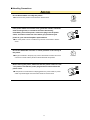
Avoid using the printer in the following locations.
● Use in such locations may result in a fire hazard or electric shock.
• Excessively humid or dusty locations
• Locations exposed to direct sunlight
• Locations exposed to high temperatures
Prohibited
• Locations near flames or moisture
●Use at the following places may result in malfunction or failure.
• Near equipment which generate a strong magnetic force or magnetic field.
●Use this printer in places where the ambient temperature is between 20 to 28°C
centigrade and humidity is between 40 to 70% (non-condensing).
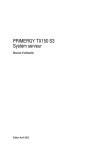
Leave plenty of space around the printer.
Approx. 2 m
●Leave sufficient space for operations in front of and behind the printer.
Approx. 3 m
Approx. 3 m
Approx. 2 m
(front side)
iii
■ Power Supply Precautions
WARNING
Do not damage the power cable, or modify it in any way. Moreover,
do not place heavy objects on the power cable, pull on the cable, or
bend it excessively.
● There may be current leakage from the damaged parts, resulting in a fire
Prohibited
hazard or electric shock.
● Do not unplug or plug in the power cable when your hands are wet, such
action may result in electric shock.
Do not connect multiple devices to the same power outlet.
● Use of the printer in such a condition may result in a fire hazard or electric
shock.
Prohibited
Do not bundle or tie-wrap the power cable.
● Use of a bundled power cable may result in a fire hazard or electric shock.
Prohibited
Make sure that the power cable is firmly inserted into the power
outlet.
● Use of a power cable when the plug is not completely inserted into the power
outlet may result in a fire hazard or electric shock.
Do not use a power cable other than the one supplied with your
printer.
● Use of a different power cable may result in a fire hazard or electric shock.
Be careful of the following when connecting a ground wire.
● [Items which allow connection to a ground wire]
• Ground terminals of electric outlets
• Ground terminals after completion of grounding work (type D)
Prohibited
● [Items which do not allow connection to a ground wire]
• Water pipes
Water pipes may have plastic parts in the middle which do not serve as grounding.
It is possible to connect a ground wire to water pipes which are approved by the waterworks department to
use for grounding.
• Gas pipes
They may cause explosions or fires.
• Ground terminals for telephone lines and lightning conductors
These may get a high-voltage current from lightning which may cause fires or electric shocks.
iv
CAUTION
The rated voltage for this printer is AC 200 - 240 V. Use an appropriate power source and voltage for the specifications of this printer.
●Using this printer with a power source and voltage which are not compatible
with the specifications may result in a fire or an electric shock.
●The operating conditions of this printer are as follows. Use a power source
which meets these conditions.
Power source and voltage: AC 200 - 240 V
Power supply frequency: 50/60Hz
When disconnecting the power cable, be sure to hold on to the plug,
and not pull on the cable itself.
●Pulling on the cable will expose the core wires, or cause damage such as
broken wires. Current leakage from the exposed or damaged areas may result
in a fire hazard or electric shock.
As a general rule, do not use an extension cord.
●Use of an extension cord may result in a fire hazard or electric shock. If you
must use an extension cord, unbundle it, and make sure that the power plug is
firmly inserted into the extension cord socket.
Make sure that the power plug can be readily unplugged at any time,
and that there are no objects placed in its vicinity.
● Objects placed in the vicinity of the power plug will prevent its removal in an
emergency.
Be sure to ground the earth terminal.
●Electric leaks which occur when no grounding wire is connected may lead to
fires or electric shocks.
●Be sure to have a ground connection.
●Be sure to have a ground connection before connecting a power plug to a
power source. Be sure to remove a ground connection after disconnecting a
power plug from a power source.
Grounding
wire required
■ Handling Precautions
WARNING
Do not disassemble or modify the printer.
●Such actions may result in a fire hazard or electric shock.
Disassembly
prohibited
If the printer makes an unusual noise, generates smoke, overheats,
emits a strange odor, or otherwise functions abnormally,
immediately turn off the power, remove the plug from the power
outlet, and either contact the store where you purchased your
printer or your nearest Graphtec representative.
●Use of the printer in such a condition may result in a fire hazard or electric
shock.
Do not use flammable aerosols or similar products in the vicinity of
the printer.
●The gas contained in the spray may cause a fire hazard or electric shock if it
comes into contact with the printer's internal electrical components.
Before moving the printer, make sure that the power switch is in the
"off" position and that the power plug has been removed from the
power outlet.
●If the printer is moved while it is still plugged into the power outlet, he power
cable may be damaged and cause a fire hazard or electric shock.
vi
Prohibited
CAUTION
Take care not to drop metallic items such as paper clips or staples,
or spill water, other fluids or flammable solvents (alcohol, benzene,
thinner, etc.) inside the printer.
●Metallic items or fluids coming into contact with the internal electrical
components may result in a fire hazard or electric shock. If such items or fluids
fall or are spilled inside the printer, immediately turn off the power, remove
the power plug from the power outlet and either contact the store where you
purchased the printer or your nearest Graphtec representative.
Do not insert your hands inside the printer during a printing
operation or when paper is being loaded.
●Moving parts inside the printer may cause injuries.
Prohibited
Appropriately connect interface cable.
●Connecting cables in the wrong direction may result in failure.
vii
■ Maintenance and Inspection Precautions
WARNING
Be sure to turn off the power and remove the power plug from the
power outlet before performing any cleaning operations.
●Failure to do so may result in a fire hazard or electric shock. Moreover, there
is a risk of injury if the printer starts to move during a cleaning operation.
Prohibited
To clean the printer, use a cloth that has been dampened with
neutral detergent and then well wrung out. Do not use volatile
solvents such as alcohol, benzene or thinner to clean the printer.
●A volatile solvent coming into contact with any of the internal electrical
components may result in a fire hazard or electric shock.
Do not apply any lubricant to mechanical sections of this printer.
●This may deteriorate the performance of this printer which may lead to
malfunction or failure.
●Subsequent short circuits or heat generation may result in a fire or an electric
Prohibited
shock.
CAUTION
At least once a year, remove the power plug from the power outlet and clean the prongs and
surrounding areas.
●A build-up of dust may result in a fire hazard.
When cleaning or checking the inside of the printer, make sure that a metallic object such as
a necklace or bracelet does not come into contact with any of the internal components.
●Such actions may result in injuries or an electric shock.
When removing paper that is jammed inside the printer, take care not to get ink from the
paper on your clothing or hands.
●Ink may adhere to your clothing or hands.
When replacing roll paper, loading paper, or removing paper that has become jammed in the
printer, take care not to cut yourself on the edges of the paper.
●Sharp paper edges may cause injuries.
viii
■ Precautions on Handling the Consumable Items
CAUTION
Do not touch any metallic parts on the print heads after a printing
operation.
●These parts will be hot, and may cause burns.
●Printing malfunctions may occur.
●There is a risk of damage from static electricity.
Do not touch the ink cartridge openings or the head section of the print heads.
●Your fingers may become stained with ink.
●Printing malfunctions may occur.
As a safety precaution, store the print heads and ink cartridges in a location out of the reach
of small children.
●If ink is licked or ingested accidentally, consult a doctor immediately.
Do not drop or shake the print heads or ink cartridges.
●Such actions may cause the ink to leak or spatter, with the risk of staining your
surroundings and clothing.
●The head section may become damaged, making the print head unusable.
The print heads are consumable items
●The print heads are consumable items. If printing is not performed correctly
even after the print heads have been cleaned or adjusted, replace them with
new ones. See "Chapter 9 Maintenance" for further details.
ix
■ For those with a cardiac pacemaker
This printer generates a faint magnetic power. Anyone with a cardiac pacemaker who feels any
abnormality should move away from this printer.
And consult a doctor immediately.
■ Precautions to observe when removing jammed paper
When removing paper that has become jammed inside the printer, take care not to get ink from the
paper on your clothing or hands. There is a possibility of ink adhering to your clothing or hands.
■ Precautions to Note When Unpacking the Printer
If the printer was stored in a location where the temperature dropped below 10°C, allow sufficient
time for the printer to become acclimatized to room temperature (the operating environment
specification is the range from 20°C to 28°C) before mounting the print heads. (We recommend
that you allow at least two hours for the printer to become acclimatized.)
■ Precautions to observe when handling the paper
● Paper may not be fed correctly and may become jammed if the leading edge of the roll paper
is not straight or if there is adhesive from the fastening tape remaining on the paper. Make sure
that the leading edge is straight before loading the paper in the printer.
● Depending on the storage conditions, the paper may become creased and/or the leading edge
may curl up. The use of creased or curled paper may cause paper jams. Remove the creased or
curled sections before loading the roll paper in the printer.
(If you are using a cut sheet, remove the creased section before loading the sheet in the printer.)
■ Notes on the print heads
Do not perform any unnecessary print head removal or mounting operations.
■ Precautions on handling ink cartridges and consumable items
WARNING
Never put ink cartridges close to a fire.
●Ink cartridges are flammable and may be a fire hazard.
Prohibited
Take care not to ingest ink or get it into your eyes.
●This may cause breathing difficulty or damage to your eyes. If ink gets into
your eyes, immediately rinse with clear water, and consult a doctor.
Prohibited
●If you ingest ink accidentally, do not try induce vomiting; immediately consult a
doctor.
Store ink cartridges in a location out of reach of small children.
If ink adheres to this printer, immediately wipe it off.
●Leaving the ink as is may cause damage to the surface coating of this printer.
Prohibited
CAUTION
Take care regarding the following issues.
●Do not use any ink other than those specified because it may not only disturb
printing quality, but also cause a malfunction which will prevent appropriate
maintenance procedures.
●Do not use ink after the expiration date because it may cause a malfunction.
●Put ink cartridges after use in a plastic bag, and dispose of them as industrial
waste. If there are any local regulations on a disposal method, comply with the
applicable rules.
●Take care not to get ink on your skin or clothing. If ink gets on your skin,
immediately rinse it off by using soap and water.
●Periodically check the amount of the waste ink in waste ink bottles to avoid an
overflow.
●When removing waste ink bottles, place paper on the floor to avoid stains from
leaked ink.
●Store ink in a dark cold place. Never store it at locations exposed to high
temperatures or direct sunlight. This may affect its performance.
●Do not disassemble ink cartridges.
●Paper for commercially available solvent ink is appropriate for this printer.
xi
PREFACE
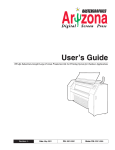
Thank you for choosing the Graphtec JS500 inkjet printer. Please read this manual thoroughly before attempting to use your new product to ensure that you use it safely
and correctly.
Notes on this Manual
(1)No part of this publication may be reproduced, stored in a retrieval system, or transmitted, in any form or
by any means, without the prior written permission of Graphtec Corporation.
(2)The product specifications and other information in this manual are subject to change without notice.
(3)While every effort has been made to provide complete and accurate information, please contact your sales
representative or nearest Graphtec vendor if you find any unclear or erroneous information or wish to make
other comments or suggestions.
(4)Notwithstanding the stipulations in the preceding paragraph, Graphtec Corporation assumes no liability for
damages resulting from either the use of the information contained herein or the use of the product.
Registered Trademarks
All names of companies, brands, logotypes, and products appearing in this manual are the trademarks or
registered trademarks of their respective companies.
Copyright
This User's Manual is copyrighted by Graphtec Corporation.
Contents
To Ensure Safe and Correct Use......................................................................................i
Safety Precautions...........................................................................................................ii
PREFACE........................................................................................................................ I
Notes on this Manual.................................................................................................................... I
Registered Trademarks................................................................................................................. I
Copyright....................................................................................................................................... I
Chapter 1 Before Using the Printer...................................................1-1
1.1
Checking the Contents of the Package.....................................................................................1-1
1.2
Parts Names and Functions......................................................................................................1-3
Front View.................................................................................................................................1-3
Main Parts.................................................................................................................................1-4
LCD Control Panel ...................................................................................................................1-5
Print Carriage............................................................................................................................1-5
Maintenance station..................................................................................................................1-6
Front cover................................................................................................................................1-6
Side of the printer body (left).....................................................................................................1-7
Side of the printer body (right)..................................................................................................1-7
Rear of the printer body............................................................................................................1-8
Rear of the printer body (right) .................................................................................................1-8
Chapter 2 Connection and Preparations...........................................2-1
2.1
Connecting to the Power Supply...............................................................................................2-1
2.2
Turning the Power On and Off..................................................................................................2-2
Turning the printer On...............................................................................................................2-2
Turning the printer Off ..............................................................................................................2-2
Turning the heater On...............................................................................................................2-3
Turning the heater Off ..............................................................................................................2-3
Turning the dryer unit On..........................................................................................................2-4
Turning the dryer unit Off..........................................................................................................2-4
2.3
Mounting the Ink Cartridges......................................................................................................2-5
2.4
Connecting the Printer to a Computer......................................................................................2-6
Connecting the USB interface cable.........................................................................................2-6
Chapter 3 Loading the Paper............................................................3-1
3.1
Feeding the paper.....................................................................................................................3-2
For printing (for normal use) ....................................................................................................3-2
Rolling up the paper..................................................................................................................3-2
Stopping the feeding of the paper.............................................................................................3-2
3.2
Taking up the paper..................................................................................................................3-3
Automatic taking up the paper..................................................................................................3-3
C-1
Removal of the paper from the Media Take-up Roller...............................................................3-3
Stopping the taking up of the paper..........................................................................................3-3
3.3
Setting a roll paper....................................................................................................................3-4
Setting a roll paper....................................................................................................................3-4
3.4
Setting the roll paper for taking-up printing...............................................................................3-9
How to set the roll paper when the Media Take-up unit is used................................................3-9
How to set a paper core.......................................................................................................3-9
How to set the roll paper on a paper core.......................................................................... 3-11
How to adjust the Media Take-up Sensor .........................................................................3-12
When the sensor is correctly adjusted...............................................................................3-14
When the sensor is not correctly adjusted.........................................................................3-14
3.5
Detecting the paper width and the position where the paper is set......................................... 3-15
Setting the paper width detection (Media Detect) function.....................................................3-15
Executing the Media Detect function......................................................................................3-16
3.6
Setting the Print Position (printing starting position)...............................................................3-17
Setting the moving direction of the Printhead Carriage..........................................................3-17
Changing the Print Position (printing starting position)...........................................................3-17
Setting the paper feeding direction.........................................................................................3-18
3.7
Setting the Margin (the margin on the paper edge) ...............................................................3-20
Chapter 4 Control Panel...................................................................4-1
4.1
Control Panel ...........................................................................................................................4-1
Control Panel ...........................................................................................................................4-1
4.2
The LCD display when the power is turned on.........................................................................4-2
Main Menu (When the Media Detect is set to "Off")..................................................................4-2
Main Menu (When the Media Detect is set to "On")..................................................................4-2
4.3
Menu Tree.................................................................................................................................4-3
Menu Tree.................................................................................................................................4-3
4.4
Functions of each menu............................................................................................................4-4
Menu 4-4
4.5
Online Mode............................................................................................................................ 4-11
Chapter 5 Software...........................................................................5-1
5.1
"GPU" and "JS RIP"..................................................................................................................5-1
Major characteristics of "GPU" and "JS RIP"............................................................................5-1
GPU (Graphtec Print Utility).................................................................................................5-1
JS RIP..................................................................................................................................5-1
Operation systems supporting "GPU" and "JS RIP".................................................................5-1
5.2
Installing "GPU".........................................................................................................................5-2
5.3
Uninstalling "GPU"....................................................................................................................5-4
5.4
Start up "GPU"..........................................................................................................................5-5
5.5
Explanation of functions in the Print Setup...............................................................................5-5
C-2
5.6
Adjusting the position of the head.............................................................................................5-8
5.7
Installing "JS RIP"...................................................................................................................5-12
5.8
Uninstalling "JS RIP" . ............................................................................................................5-13
5.9
Start up "JS RIP".....................................................................................................................5-14
5.10
Setting up models of JS RIP...................................................................................................5-14
5.11
Printing from "JS RIP".............................................................................................................5-17
5.12
Aborting the printing from the printer......................................................................................5-17
5.13
Canceling printing from "JS RIP"............................................................................................5-17
Chapter 6 Cleaning system...............................................................6-1
6.1
Purpose of head cleaning.........................................................................................................6-1
6.2
Jam Test....................................................................................................................................6-1
6.2.1 Purpose of the Jam Test..................................................................................................6-1
6.2.2
How to perform the Jam Test.....................................................................................6-1
6.3
Firing (empty ejection) .............................................................................................................6-2
6.3.1
Purpose of the Firing operation.................................................................................6-2
6.3.2
How to perform the Firing..........................................................................................6-2
6.3.3
How to set the Firing Volume (the amount of empty ejections).................................6-2
6.4
Printhead Cleaning...................................................................................................................6-3
6.4.1
Auto Cleaning............................................................................................................6-3
6.4.2
Auto Cleaning (Heavy)...............................................................................................6-4
6.4.3
Manual Cleaning........................................................................................................6-5
6.5
Cleaning during printing............................................................................................................6-7
6.5.1
Flash Mode................................................................................................................6-7
In the case that the set value is "0003"................................................................................6-8
In the case that the set value is "0015"................................................................................6-8
6.5.2
Cleaning by the Pause (pausing printing by manual operation) function...................6-9
6.6
Changing the Firing Volume (the amount of empty ejections) ...............................................6-10
6.7
Automatic Routine Cleaning...................................................................................................6-10
Chapter 7 Setting the heater.............................................................7-1
7.1
Outline.......................................................................................................................................7-1
7.2
Front Heater / Pre Heater.........................................................................................................7-2
7.2.1
Explanation of functions.............................................................................................7-2
7.2.2
Setting method...........................................................................................................7-2
7.3
Plat form Heater........................................................................................................................7-3
7.3.1
Explanation of functions.............................................................................................7-3
7.3.2
Setting method...........................................................................................................7-3
7.4
P/H Heater................................................................................................................................7-4
7.4.1
Explanation of functions.............................................................................................7-4
7.4.2
Setting method...........................................................................................................7-4
C-3
7.5
Time to LPM (Low Power Mode) . ............................................................................................7-5
7.5.1
Time to LPM...............................................................................................................7-5
7.5.2
Setting method...........................................................................................................7-5
Chapter 8 Dryer Unit.........................................................................8-1
8.1
Connecting the power supply....................................................................................................8-1
8.2
Turning the power ON/OFF.......................................................................................................8-2
Turning the dryer unit On..........................................................................................................8-2
Turning the dryer unit Off .........................................................................................................8-2
8.3
Adjustment of the angle (direction of the wind) of the Dryer Unit..............................................8-3
Chapter 9 Maintenance.....................................................................9-1
9.1
Replacing the Ink Cartridges.....................................................................................................9-1
Ink End 9-1
Replacing the ink cartridges......................................................................................................9-1
9.2
Replacing the Cleaning Roller..................................................................................................9-3
Replacement interval of the Cleaning Roller . ..........................................................................9-3
How to replace the Cleaning Roller..........................................................................................9-3
Handling of the hardened Cleaning Roller ...............................................................................9-3
9.3
Waste ink bottles.......................................................................................................................9-4
9.4
Periodical maintenance.............................................................................................................9-5
Daily maintenance....................................................................................................................9-5
Moistening the sponge in the cap with Ink Cleaning Solution..............................................9-5
Checking the waste ink bottles............................................................................................9-6
Check for interfusion of air (air bubbles) in the printhead tubes..........................................9-6
Weekly maintenance.................................................................................................................9-7
Cleaning of the capping unit................................................................................................9-7
Clean the Cleaning Roller with Ink Cleaning Solution..........................................................9-8
9.5
Handling of the printer when it will not be used for a while.......................................................9-9
Removal of ink.....................................................................................................................9-9
Cleaning with Ink Cleaning Solution and fill the tubes with Ink Cleaning Solution...............9-9
9.6
Handling of the printer which has been turned off for a while................................................. 9-11
Moistening the Cleaning Roller with Ink Cleaning Solution................................................ 9-11
Removal of Ink Cleaning Solution . ................................................................................... 9-11
Filling ink............................................................................................................................ 9-11
Chapter 10 What to Do if This Happens.........................................10-1
10.1
When an Error Message is Displayed.....................................................................................10-1
1. Warning:..............................................................................................................................10-1
2. Error: 10-1
Errors listed below indicate the detail for further check when self test fails............................10-1
10.2
Troubleshooting......................................................................................................................10-2
The Printer Does Not Operate Correctly.................................................................................10-2
C-4
When Printing is not Satisfactory............................................................................................10-2
If the Paper Becomes Jammed...............................................................................................10-3
Occurrence of an abnormal sound..........................................................................................10-3
Chapter 11 Specifications, optional items and consumable items.................................... 11-1
11.1
Standard Specifications.......................................................................................................... 11-1
11.2
Optional items......................................................................................................................... 11-2
11.3
Consumable items.................................................................................................................. 11-2
Index......................................................................................................................index-1
C-5
Chapter 1 Before Using the Printer
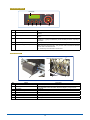
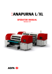
1.1 Checking the Contents of the Package
Check to confirm that all of the items shown below are present. If any item is missing, promptly contact the
store where you purchased your printer or your nearest Graphtecrepresentative.
No.
1
Name
Stand
Q'ty
No.
1 Set
10
flange
Name
Q'ty
4
11
Plastic syringe
2
12
ø3/5 Soft tube
1
13
Outlet tube assembly
14
JS500-18:8, JS501-18:12
USB interface cable
1
15
Power cable (Printer, Heater)
2
16
Power cable (Dryer)
1
17
Bursh
1 Set
18
Non-woven fabric
1 Set
Stand R/L, Center bar
2
3
4
5
6
7
Dryer unit
Printhead
JS500-18:8, JS501-18:12
Printhead clamp
JS500-18:8, JS501-18:12
Media Take-up Roller
Media Feeding Roller
Rubber Roller
1 Set
8/12
8/12
1
8/12
1
1
8
Installed on the Printer
Media Tension Bar unit
1 Set
9
Installed on the Printer
Waste Ink Tank
2
1-1
No.
Name
Q'ty
No.
1 Set
29
Hex-head wrench (5 mm/4 mm)
1
Software CD-ROM
1
30
Jig, Printhead height adjustment
2
21
User Guide CD-ROM
1
31
Cleaning roller
1
22
User's Manual
1
32
Installed on the Printer
Jig, Ink installing
1
19
One-off glove
20
23
Setup Guide
1
24
Screw (Screw for Printhead fixation)
16/24
25
JS500-18:16, JS501-18:24
Positining Pin
18/26
26
JS500-18:18, JS501-18:26
Plastic block (For Printhead fixation)
16/24
27
JS500-18:16, JS501-18:24
Spoid (5 cc)
3
28
Solution bottle (250 ml)
1
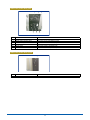
1-2
Name
Q'ty
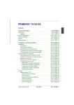
1.2 Parts Names and Functions
Front View
8
4
3
2
1
10
9
5
6
12
7
11
No.
1
Name
2
3
4
5
6
7
8
9
10
11
Top cover
Front cover
Front cover clear
Rear cover
Right upper cover
Right bottom cover
Side cover (Right)
Left upper cover
Left bottom cover
Side cover (Left)
Main cleaning position
12
Print Head Maintenance position
Functions
The upper front cover.
The front cover.
The front clear cover.
The upper rear cover.
The upper right cover.
The cover at the cleaning position.
The right side cover.
The upper left cover.
The cover for the maintenance station.
The side cover.
The Home Position of printheads.
Capping and Auto Cleaning of the printheads are performed at this position.
At the initial setup: Installation of the printheads and initial pouring of ink are
performed at this position.
During normal use: Recovery procedures for nozzles of the printheads are
performed in case that maintenance is required due to
faded print.
1-3
Main Parts
11
5
4
2
1
3
9
3
8
No.
10
7
Name
1
LCD Control Panel
2
3
Print Carriage
Waste Ink Tank
4
Heating board
5
6
Dryer unit
Media Take-up Roller
7
8
Media Feeding Roller
Media Take-up Sensor
9
10
11
6
Left flange
Right flange
Dryer unit Switch
Functions
Confirmation of the printer status and various settings can be performed with
this panel.
This part moves the printheads.
These tanks store waste ink which is discharged during the initial pouring of
ink or recovery procedures of the printheads.
One is installed at the main cleaning position, and the other one is installed at
the PH Maintenance position.
This board warms up media to an appropriate temperature for better printing
quality.
This unit is used to accelerate drying of ink after printing.
This roller takes up the media after printing. It is used for printing on a long
piece of paper.
This roller is used to set media (roll paper).
This sensor detects the media after printing. After the printed media reaches a
certain length, the Media Take-up Roller starts taking up the media.
This part fixes the media (roll paper) onto the roller.
This part fixes the media (roll paper) onto the roller.
This switch turns the Dryer unit on or off.
1-4
LCD Control Panel
LCD Display
1
No.
2
3
4
5
Name
ONLINE Key
2
ESC Key
3
FUNC Key
4
5
ENTER Key
POSITION Key (
Functions
This key switches online/offline. Press this key for several seconds to pause
printing.
This key cancels the current job, and returns the menu display to one position
above.
FUNC button - This button switches functions of this printer. Press the
[FUNC] key + [ ] key simultaneously to execute test print when no printing is
performed.
This key confirms the selection of an item or the setting of a value.
<Operations on the Control Panel>
▲▼ These keys scroll the menu. They are also used to increase or decrease
the set value of the selected item.
These keys move the cursor on the menu.
→
→)
▲
▲
→
→
▲
1
Print Carriage
1
When the head cover is removed
5
7
6
3
2
No.
1
Name
2
Head cover
P.H. Adjustment lever
3
4
5
6
7
8
Printhead
Printhead-carriage
Inlet tube
Outlet tube
Outlet tube cap
Printhead clamp
8
4
Functions
The cover to protect the Print Carriage.
The lever to adjust the height of the printheads.
If the printheads scratch the media, adjust their height by using this lever.
Printheads.
This part moves the printheads.
These tubes supply ink to the printheads.
These tubes are used for introducing ink to the printheads or for maintenance.
These caps are for outlet tubes.
These parts are used to fix the printheads and the tubes.
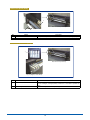
1-5
Maintenance station
1
3
2
No.
Name
1
Cleaning roller
2
3
Capping unit
Media Set Lever
Functions
This roller cleans the printheads. The cleaning roller is a replaceable item.
Please replace it with a new one if it becomes dirty.
These parts are used for capping the printheads.
This lever is used to set or remove media.
Front cover
1
3
No.
4
2
Name
1
Pinch roller
2
3
4
Printing Platform
Media guide
(Y-encoder)
Functions
These parts are important parts to forward paper. They retain the paper in
place.
The printheads pass on this part during printing.
This part prevents the paper edges from floating.
This part is an important part to move the Printhead Carriage.
1-6
Side of the printer body (left)
1
4
No.
1
2
3
4
5
6
2
5
3
6
Name
Functions
Heater Switch
Media feeding System switch
Media take-up System switch
Heater soket
Power soket
Power Switch
The switch for the Heater (Pre Heater, Front Heater, Plat form Heater).
The switch for the media feeding system.
The switch for the media take-up system.
The dedicated power supply switch for the Heater.
The power socket on the printer body.
The power switch of the printer body.
Side of the printer body (right)
1
No.
1
Name
USB interface connector
Functions
The connector for a USB interface cable.
1-7
Rear of the printer body
2
Rear view of the printer body
2
No.
1
2
1
Name
Rubber Roller
Media Tension Bar
Functions
This part is an important part to stretch the media for better printing quality.
This part is an important part to stretch the media for better printing quality.
Rear of the printer body (right)
1
Rear view of the printer body
2 (Cyan, Magenta, Yellow, Black)
No.
Name
1
Ink holder C, M, Y, BK
2
Ink cartridge C, M, Y, BK
Functions
This is where ink cartridges are installed. Check the C, M, Y and BK labels on
the ink cartridges, and appropriately install them in the holders specified for
each.
Four ink cartridges, which are Cyan, Magenta, Yellow and Black.
1-8
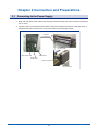
Chapter 2 Connection and Preparations
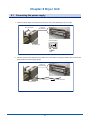
2.1 Connecting to the Power Supply
1. Make sure that all the power switches (for the printer, heater and dryer) are at the off position (indicated by
the "O" mark).
2. Connect one end of the attached power cables to the power sockets (for the printer, heater and dryer) on
the printer body and the other end to an AC power outlet of the rated supply voltage.
Left side of
the printer body
Left front of
the printer body
Heater Power Soket
Power Switch
Power Soket
Dryer Unit Switch
Dryer Unit Soket
2-1
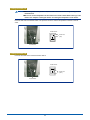
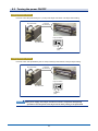
2.2 Turning the Power On and Off
Turning the printer On
Press the "ON" side (indicated by the "|" mark) of the power switch of the printer on the left side of the printer
body. The printer is turned on and initial operations start.
Press here (ON)
Power Switch
Turning the printer Off
CAUTION ●To maintain the appropriate condition of the printheads, this printer automatically
performs cleaning operations when it is in the standby mode. It is recommended to
leave the power on.
To turn the printer off, press the "OFF" side (indicated by the "O" mark) of the power switch of the printer on
the left side of the printer body.
Press here (OFF)
Power Switch
2-2
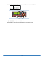
Turning the heater On
CAUTION ●When the power of the printer is off, the heater cannot be turned on by turning on the
Heater Switch.
●Be sure to set the temperature of the heater on the Control Panel before turning on the
heater. See "Chapter 7 Setting the heater" for setting the temperature of the heater.
Press the ON side of the Heater Switch. The printer is turned on and the temperature increases to the set
value.
Heater Switch
Press here
(ON)
Heater Switch
Turning the heater Off
Press the OFF side of the Heater Protective Switch.
Heater Switch
Press here
(OFF)
Heater Switch
2-3
Turning the dryer unit On
Press the "ON" side (indicated by the "|" mark) of the Dryer Unit Switch. The dryer starts rotating.
Dryer Unit Switch
Left front of
the printer body
Dryer Unit Switch
Dryer Unit Soket
Press here
(ON)
Turning the dryer unit Off
Press the "OFF" side (indicated by the "O" mark) of the Dryer Unit Switch. The dryer stops rotating.
Dryer Unit Switch
Left front of
the printer body
Dryer Unit Switch
Dryer Unit Soket
Press here
(OFF)
2-4
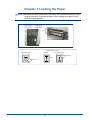
2.3 Mounting the Ink Cartridges
CAUTION ●Do not drop or shake the ink cartridges. Such actions may cause the ink to leak or
splatter which may lead to staining of the immediate surroundings or on clothing.
●Do not insert and remove ink cartridges to and from the printer body too frequently.
Inserting and removing cartridges five or more times may result in leakage of the ink
from the insertion port.
●After removing ink cartridges, do not point the insertion port downward. Ink may leak
from the insertion port.
Set the ink cartridges in the ink holders on the right side of the rear of the printer body. Insert them slowly
along the insertion port of the ink holders.
Ink holder
Rear view of the printer body
Ink cartridge
2-5
2.4 Connecting the Printer to a Computer
Connecting the USB interface cable
Connect the printer body and a PC with a USB interface cable via a USB interface connector. The USB
interface cable has connectors with different shapes for a PC and for the printer. Be sure to check the shape of
each connector and appropriately connect the cable.
USB Interface Connector
Right side of
the printer body
USB connector
To a PC
USB2.0
Interface cable
CAUTION ●Insert the USB interface cable securely into the USB interface connector.
2-6
Chapter 3 Loading the Paper
CAUTION ●The Media Feeding System Switch and the Media Take-up System Switch have a threestage structure. See "3.1 Feeding the paper", and "3.2 Taking up the paper" for the
functions of these switches.
Media feeding
System Switch
Media take-up
SystemSwitch
Left side of the printer body
Explanation on the switch
The ON side of SW-1
SW OFF
The ON side of SW-2
Press here
OFF
Press here
3-1
3.1 Feeding the paper
CAUTION ●Usually, set the switch to the "=" side.
Media Feeding
System Switch
Media Take-up
System Switch
Media Feeding System Switch
FEEDING
TAKE UP
Continuous reverse rotation
OFF
Automatic
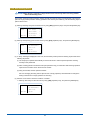
For printing (for normal use)
Set the Media Feeding System Switch to the "=" side. The sensor checks for the presence of paper, and the
detected paper is automatically fed out.
CAUTION ●Be sure to set the switch to the "=" side (automatic feeding) when printing. If printing
occurs while the Media Feeding System Switch is set to the "O" side or the "—" side, it
may result in a failure.
Rolling up the paper
Set the Media Feeding System Switch to the "—" side. While the switch is set to the "—" side, the Media
Feeding Roller rotates in a reverse direction which rolls up the paper on the roll paper stocker.
Stopping the feeding of the paper
Setting the Media Feeding System Switch to the "O" side stops the feeding.
CAUTION ●Usually, set the switch to the "=" side.
3-2
3.2 Taking up the paper
This printer allows automatic taking up of the media after printing.
Media Feeding
System Switch
Media Take-up
System Switch
Media Feeding System Switch
FEEDING
TAKE UP
Continuous reverse rotation
OFF
Automatic
Automatic taking up the paper
Set the Media Take-up System Switch to the "=" side. The sensor checks for the feeding of paper, and the
paper is automatically taken up.
Removal of the paper from the Media Take-up Roller
Set the Media Take-up System Switch to the "—" side. While the switch is set to the "—" side, the Media
Take-up Roller rotates in a reverse direction which allows the paper to move backward (remove from the
roller).
Stopping the taking up of the paper
Set the Media Take-up System Switch to the "O" side.
3-3
3.3 Setting a roll paper
Setting a roll paper
CAUTION ●When setting a roll paper in the printer, try to avoid touching the printing surface
directly with your hands. Fingerprints on the printing surface will adversely affect ink
adhesion.
●Take care not to cut your fingers on the edges of the paper when handling it.
1. When the power of the printer is on, set the Media Feeding System Switch to the off ("O") side.
FEEDING SW
SW OFF
OFF
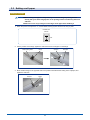
2. Set the position of the flange, tighten the setscrews and set a roll paper on the flange.
Media Feeding Roller
Flange
Setscrew
Roll Paper
2
1
3
3. Move another flange on the opposite side to the position which allows the setting of the roll paper, and
tighten the setscrew.
Flange
Setscrew
2
1
3-4
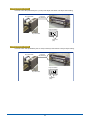
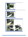
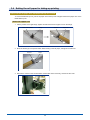
4. Remove the screws on the stocker holder on both sides of the rear body, and remove the cover.
5. Check the direction in which the paper is wound, and install the Media Feeding Roller with the roll paper on
the stocker holder.
6. Fix the cover of the stocker holder with mounting screws.
Left side of the rear of
the printer body
Right side of the rear of
the printer body
3-5
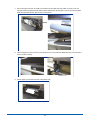
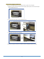
7. Pull out the paper from the roll, making sure that the left and right sides are pulled out evenly. Then, set
the paper around the Rubber Roller and the Media Tension Bar. Set the paper correctly around the Rubber
Roller and the Media Tension Bar as shown in the photos.
8. Insert the paper from the rear of the printer body. Be sure to check that the Media Set Lever is lowered (and
the Pinch roller is raised).
Media Set Lever
9. Pull the paper out from the front side of the printer body.
3-6
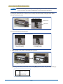
10.Take up the slack of the paper, and set the Media Set Lever to the LOAD position.
Media Set Lever
11.Set the Media Guide.
Media
Media Guide
To use the Media Take-up unit, pull a sufficient length of paper out, and fix it on a paper core by using tape.
(See "3.4 Setting a roll paper for taking-up printing" described later).
Fix with tape
Slack the paper off
3-7
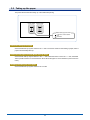
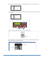
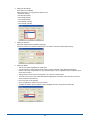
12.When the paper width detection (Media Detect) is set to "on", raising the Media Set Lever leads to the
following display on the LCD and switches to the paper width detection mode.
Media Set Lever
Menu
Media Detect
Start: 0000 mm
Length: 0000 mm
Offline
Press the [ENTER] key to perform the paper width detection and to store the position where the paper is
currently set and the paper width on the printer.
Press the [ESC] key to cancel the paper width detection. In this case, the value which was acquired by the
immediately previous paper width detection has been stored on the printer.
When the power of the printer is off, turning on the power while the paper width detection (Media Detect)
is set to "ON", and the set lever is raised (the push roller is lowered), the printer turns to the paper width
detection mode. (See "3.5 Detecting the paper width and the position where the paper is set" described
later for how to set the paper width detection).
3-8
3.4 Setting the roll paper for taking-up printing
How to set the roll paper when the Media Take-up unit is used
To use the Media Take-up unit, pull out the paper so that the tip of the roll paper reaches the paper core on the
Media Take-up unit.
How to set a paper core
1. Set the position of the right flange, tighten the setscrews and set a paper core on the flange.
Media Take-up Roller
Flange
Setscrew
Paper core
2
1
3
2. Move the left flange to the position which allows setting of the roll paper, and tighten the setscrew.
Setscrew
Flange
2
1
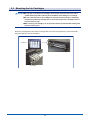
3. Remove the screws on the stocker holder on both sides of the front body, and remove the cover.
3-9
4. Check the direction of the Media Take-up, and set it on the stocker holder.
5. Fix the cover of the stocker holder with mounting screws.
Left side of the front of
the printer body
Right side of the front of
the printer body
3-10
How to set the roll paper on a paper core
When you use the Media Take-up unit, fix the paper securely on a paper core by using tape.
1. Referring to the above-mentioned method to set the roll paper, pull the paper out until it reaches the paper
core on the Media Take-up unit.
Pulling out the paper media
2. Take up the slack of the paper, and raise the Media Set Lever.
Take up the slack of the paper
Media Set Lever
3. Fix the paper on the paper core by using tape.
Fix with tape
If the position of the paper core does not fit, adjust the position by changing the position of the flange.
3-11
How to adjust the Media Take-up Sensor
CHECKPOINT
●The Media Take-up Sensor may not work depending on the indoor conditions where it
is used. In such a case, make an adjustment by using the following method.
Set the Media Take-up System Switch to the "=" side (automatic taking-up paper), adjust the sensitivity
by turning the adjustment knob so that the sensor correctly detects the feeding of the paper which allows
automatic taking-up the paper.
Media Take-up Sensor
Adjustment knob
Sensor LED
The sensor LED lights as indicated below:
Media Take-up Sensor
Sensor LED lights red/green The sensor is detecting.
Sensor LED lights green It is operating normally.
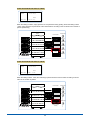
1. Feed the paper to the position of the Media Take-up Sensor.
Pulling out the paper media
Slack the paper off
(1) Select [4.Print Para] from the main menu by using [▲▼] (Up/Down) keys, and press the [ENTER] key.
Menu
Offline
1.Ink Status
+
2.Heat Status
+
3.CleaningTool
+
4.Print Para
+
3-12
(2) Select [1.Print Post] from the sub menu by using [▲▼] (Up/Down) keys, and press the [ENTER] key.
Menu
Offline
1.Print Post.
-
2.Bi-dir.Adj.
-
3.Print Speed
-
4.Feed Speed
-
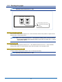
(3) Feed the paper until the paper reaches the height of the Media Take-up Sensor by pressing the [FUNC]
key + [▼] key.
Menu
1.Print Post.
Start: 0100 mm
Offline
Length: 0000 mm
FUNC
Press these
▼
buttons simultaneously
2. Set the Media Take-up System Switch to the "=" side (automatic taking-up).
TAKE UP SW
The ON side of SW-2
Press here
3. Adjust the sensitivity by turning the adjustment knob so as the sensor correctly detects the feeding of the
paper which allows automatic taking-up the paper.
Media Take-up Sensor
Adjustment knob
Sensor LED
3-13
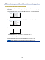
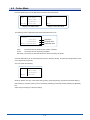
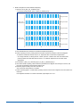
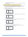
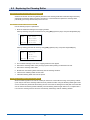
When the sensor is correctly adjusted
Front side
Front side
Media Take-UP Sensor
The sensor detects the paper,
and taking-up starts.
Media Take-UP Sensor
The sensor does not detect the paper,
and taking-up stops.
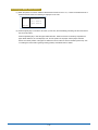
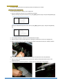
When the sensor is not correctly adjusted
When the sensor output is too weak
When the sensor output is too strong
Front side
Front side
Media Take-UP Sensor
The sensor cannot detect the paper,
and taking-up does not occur.
In this case, turn the adjustment knob
gradually to the right to increase the
sensor output.
Media Take-UP Sensor
The sensor detects objects other than the
paper, and the roller does not stop after
taking-up of the paper is finished.
In this case, turn the adjustment knob
gradually to the left to decrease the sensor
output.
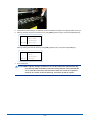
The adjustment knob of the sensor
Media Take-up Sensor
Adjustment knob
Sensor LED
3-14
3.5 Detecting the paper width and the position where the paper is set
Setting the paper width detection (Media Detect) function
This printer automatically detects the paper width and the position where the paper is set. The detected value
is reflected in the Print Position (printing starting position) setting. Set the Media Detect function by using the
following steps.
(1)Select [5.Application] from the main menu by using [▲▼] (Up/Down) keys, and press the [ENTER] key.
Menu
Offline
2.Heat Status
+
3.CleaningTool
+
4.Print Para
+
5.Application
+
(2)Select [5.Media Detect] from the sub menu by using [▲▼] (Up/Down) keys, and press the [ENTER] key.
Menu
2.PF Heater
3.FH/Pre Heater
4.PH Heater
Offline
5.Media Detect
(3)Enable (on) or disable (off) the Media Detect function.
Menu
5.Media Detect
on
Offline
Press [▲▼] (Up/Down) keys to toggle between on and off. (Default value: on)
on: Enabled (default setting)
off: Disabled
(4)Press the [ENTER] key to store the set value. Press the [ESC] key to cancel the set value.
CHECKPOINT
●The immediately preceding set value is enabled as the current set value.
3-15
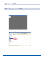
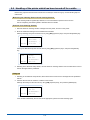
Executing the Media Detect function
(1)When the printer is turned on while the Media Detect function is set to "on", or when the media set lever is
lowered and then raised, the following is displayed on the LCD.
Menu
Media Detect
Start: 0000 mm
Length: 0000 mm
Offline
(2)Press the [ESC] key to cancel the set value. (In this case, the immediately preceding set value remains as
the current set value)
Press the [ENTER] key to start the paper width detection. When the sensor successfully completes the
paper width detection, the LCD displays "OK", and the position of the paper and the paper width are
stored. The stored position of the paper is reflected in the set value for the Print Position (Print Post). See
"3.6 Setting the Print Position (printing starting position)" described later for details.
3-16
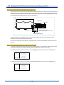
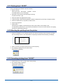
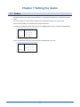
3.6 Setting the Print Position (printing starting position)
Setting the moving direction of the Printhead Carriage
Paper feeding direction
The set position of the paper which is loaded by the Media Detect function (a value from the Home Position to
the set position of the paper) is reflected in the set value of the Print Position (Print Post) after adding the set
value for the "Margin" (a set value for the margin on the paper edge). See "3.7 Setting the Margin (the margin
on the paper edge)" described later on how to set the "Margin".
Home Position
Print Head
Media
Paper width
Paper set position (mm)
(Detected by the Media Detect function)
Margin (mm)
Print Position (mm)
(Paper set position+Margin)
▲
Press the [FUNC] key + [ ] position key to move the Printhead Carriage to the Print Position to allow
confirmation of the actual printing starting position.
▲
Press any key (other than the [FUNC] key or [ ] position key) to return the Printhead Carriage to the Home
Position.
Changing the Print Position (printing starting position)
To change the setting of the Print Position (printing starting position), use the following steps. (Use the same
steps when setting the Print Position manually while the Media Detect function is set to "off").
(1)Select [4.Print Para] from the main menu by using [▲▼] (Up/Down) keys, and press the [ENTER] key.
Menu
Offline
1.Ink Status
+
2.Heat Status
+
3.CleaningTool
+
4.Print Para
+
(2)Select [1.Print Post.] from the sub menu by using [▲▼] (Up/Down) keys, and press the [ENTER] key.
Menu
Offline
1.Print Post.
-
2.Bi-dir.Adj.
-
3.Print Speed
-
4.Feed Speed
-
3-17
] (left/right) keys, and change the value by using [▲▼]
▲
▼
(3)To change the value, move the cursor by using [
(up/down) keys.
Menu
1.Print Post.
Offline
Length: 0000 mm
Start: 0100 mm
Press the [FUNC] key + [▲▼] position key to move the Printhead Carriage to the Print Position to allow
confirmation of the actual printing starting position.
▲
Press any key (other than the [FUNC] key or [ ] position key) to return the Printhead Carriage to the Home
Position.
(4)Press the ENTER key to store the set value.
Press the ESC key to cancel the set value.
CHECKPOINT
●The immediately preceding set value remains as the current set value.
Setting the paper feeding direction
Set the Print Position (printing starting position) in the paper feeding direction by using the following steps.
(1)Select [4.Print Para] from the main menu by using [▲▼] (Up/Down) keys, and press the [ENTER] key.
Menu
Offline
1.Ink Status
+
2.Heat Status
+
3.CleaningTool
+
4.Print Para
+
(2)Select [1.Print Post.] from the sub menu by using [▲▼] (Up/Down) keys, and press the [ENTER] key.
Menu
Offline
1.Print Post.
-
2.Bi-dir.Adj.
-
3.Print Speed
-
4.Feed Speed
-
3-18
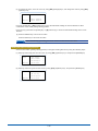
(3)Press the [FUNC] key + [▲(▼)] position key to move the paper to the desired printing position.
Menu
1.Print Post.
Offline
Length: 0000 mm
Start: 0100 mm
FUNC
Press these
▼
buttons simultaneously
FUNC
Press these
▼
buttons simultaneously
[FUNC] key + [▼] position key: Feed the paper forward
[FUNC] key + [▲] position key: Feed the paper backward
(4)After deciding the paper position, press the ENTER key to return to the menu screen.
3-19
3.7 Setting the Margin (the margin on the paper edge)
Set the margin (mm) between the paper edge detected by the Media Detect function and the printing starting
position. Use the following steps to set the value.
(1)Select [5.Application] from the main menu by using [▲▼] (Up/Down) keys, and press the [ENTER] key.
Menu
Offline
2.Heat Status
+
3.CleaningTool
+
4.Print Para
+
5.Application
+
(2)Select [6.Margin] from the sub menu by using [▲▼] (Up/Down) keys, and press the [ENTER] key.
Menu
3.FH/Pre Heater
4.PH Heater
5.Media Detect
6.Margin
(3)To change the value, move the cursor by using [
] (left/right) keys, and change the value by using [▲▼]
▲
▼
Offline
(up/down) keys.
Setting range: 0000 - (Default value: 0020)
Menu
6.Margin
0020
Offline
(4)Press the [ENTER] key to store the set value.
Press the [ESC] key to cancel the set value. (In this case, the immediately preceding set value remains as
the current set value)
(5)To reflect the set Margin value to the printing starting position (Print Position), be sure to execute the Media
Detect (paper width detection) function again after setting the margin. The set Margin value is reflected in
the Print Position only after Media Detect is executed.
3-20
Chapter 4 Control Panel
This chapter describes basic functions of the keys and the Menu function of the Control Panel.
4.1 Control Panel
Control Panel
LCD Display
ONLINE Key
No.
POSITION Key
Name
2
LCD Display
ONLINE Key
3
ESC Key
4
FUNC Key
Functions
The LCD Display shows various menus.
This key switches Online/Offline.
Press this key to toggle between Online and Offline, and [Online] or [Offline] is
shown on the LCD Display.
When this key is pressed for several seconds during printing, the printing is
paused and the Online menu is displayed.
This key cancels the current job, and returns the menu display to one position
above.
This key is used with the Direction Key to specify operations.
Press the [FUNC] key + [ ] key simultaneously to execute the test print when
no printing is performed.
This key confirms the selection of an item or the setting of a value.
(1) Operations on the Control Panel
▲▼ (Up/Down) Key:Moves the cursor upward or downward. They are
used to increase or decrease numerical values on the
set value input screen.
(Left/Right) Key:They are used to specify the digit when increasing or
decreasing numerical values on the set value input
screen.
(These keys move the cursor leftward or rightward).
(2) Other functions
See "4.4 Functions of each menu" described later for each function.
5
6
ENTER Key
POSITION Key
▲
▼
▲
1
FUNC Key
ESC Key
ENTER Key
4-1
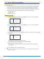
4.2 The LCD display when the power is turned on
When the power is turned on, System, Y-Monitor, X-Monitor and PrintHead are checked after the Printer Name
is displayed.
Booting
> System
> Y-Motor
Verx.xx
> X-Motor
Check
> PrintHead
After these checks are complete, operational checks of the Y Monitor and X Monitor are performed, and then
the Auto Cleaning is performed.
(Auto Cleaning operations take around 2 minutes.)
After all the checks are successfully completed, the following Main Menu is displayed.
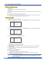
Main Menu (When the Media Detect is set to "Off")
Menu
Offline
1.Ink Status
+
2.Heat Status
+
3.CleaningTool
+
4.Print Para
+
The "+" sign which is displayed on the right-hand edge of the Menu indicates that the item has subordinate
items in the menu hierarchy.
When "-" is displayed, it indicates that the item is in the lowest menu hierarchy.
Main Menu (When the Media Detect is set to "On")
Menu
Media Detect
Start: 0000 mm
Length: 0000 mm
Offline
Pressing the [ENTER] key displays the Main Menu screen after Media Detect operations.
Pressing the [ESC] key displays the Main Menu screen without Media Detect operations.
4-2
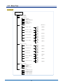
4.3 Menu Tree
Menu Tree
Main Menu
1.Ink Status
2.Heat Status
3.CleaningTool
1.Firing
2.Jam Test
3.PH Maintenance
4.Home Post.
5.Clean
6.Clean(Heavy)
7.Parking
(Defoult)
4.Print Para.
1.Print Post.
0100
(0300)
2.Bi-dir. Adj.
1999
0000
(0030)
5.Firing Vol.
0100
High
Norm
Low
High
Norm
Low
0000
6.Flash Mode
0200
0000
3.Print Speed
4.Feed Speed
0300
(Norm)
(Norm)
(0050)
(0001)
5.Application
1.Time to LPM
0000
2.FH and Pre
1999
0000
3.Platform
0099
0000
4.PH Heater
0099
0000
6.Margin
0099
on
off
0000
7.Fan Velocity
0999
0000
5.Media Detect
0999
6.Maintenance
1.Moving Test
2.License
3.About
4.Default Set.
7.Engineer Set.
1.PH Maint.Post.
2.Printer Width
3.Parking Post.
4.Y Test Speed
5.X Test Speed
4-3
(0060)
(0045)
(0045)
(0030)
(on)
(0020)
(0010)
4.4 Functions of each menu
Menu
Main Menu
Sub Menu
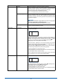
1. Ink Status
Function description
Displays the status of each ink cartridge.
Menu
Offline
Ink Status
Ch
C
M
Y
K
Rn
_
_
_
_
Al
_
_
_
_
Menu
Offline
Ch:
Rn:
Al:
Ink Status
Ch
C
M
Y
K
Rn
_
_
_
_
Al
_
_
_
_
Indicates each ink cartridge (Channel).
Indicates the pump which is operating.
Indicates the Channel for which an alarm is activating.
When ink cartridges are not set or when ink cartridges are empty, an alarm
is activated, and the Channel is displayed.
After the relevant ink cartridge is replaced, the alarm is automatically
deactivated, and the printer returns to its normal operation.
▲▼
Pressing the [Direction] key on this screen allows cleaning operations
(positive pressure) for the ink cartridge which corresponds to each key.
See "6.4.3 Manual Cleaning" described later for details.
[ ]Key: Cyan [▲]Key: Magenta
[ ]key: Yellow [▼]Key: Black
2. Heat Status
Displays the status of each heater.
Menu
Offline
Heat Status
FP
PF
PH
Tem. 00
00
00
Set. 00
00
00
Menu
Offline
Heat Status
FP
PF
PH
Tem. 00
00
00
Set. 00
00
00
FP: Front Heater and Pre Heater
PF: Plat from Heater
PH: PH Heater
Tem: Indicates the current heater temperature.
Set: Indicates the set heater temperature.
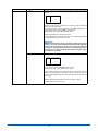
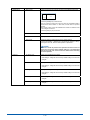
3. Cleanig Tool
1. Firing
Performs an empty ejection of ink to discharge the ink which becomes
thick in the Print Head Nozzle.
Pressing the [ENTER] key displays a "Busy" message on the LCD, and
then an empty ejection is performed.
The "Busy" message disappears after the empty ejection is complete.
The number of times the empty ejection function is performed can be
changed on the Sub Menu "Firing Vol." of the Menu "Print Para".
To increase the number of times of the empty ejection function is
performed, increase the set value for the "Firing Vol."
See "6.3 Firing (empty ejection)" described later for details about firing
operations.
2. Jam Test
Press the [Enter] key to perform the Test Print.
See "6.2 Jam Test" described later for details about the Jam Test.
3. PH Maintenance
Press the [Enter] key to move the P/H carriage to the PH Maintenance
Position.
4. Home Post
Press the [Enter] key to move the P/H carriage to the Home Position.
4-4
Main Menu
Sub Menu
Function description
5. Clean
Press the [Enter] key to perform the Cleaning operations.
The P/H carriage moves to the Home Position, and the ink pump
operates for around 6 seconds. After a waiting time (operations stop) of
around 60 minutes, roller cleaning operations are performed.
The Firing is performed to complete this operation.
See "6.4 Printhead Cleaning" described later for details.
6. Clean (Heavy)
Press the [Enter] key to perform the Heavy Cleaning operations.
The P/H carriage moves to the Home Position, and the ink pump
operates for around 15 seconds. After a waiting time (operations stop)
of around 70 minutes, roller cleaning operations are performed, and the
printheads are capped.
CAUTION
This function consumes a huge amount of ink. Use it only when
recovering nozzles after a robust fixing of ink.
See "6.4. Printhead Cleaning" described later for details.
Pressing the [Enter] key moves the P/H carriage to the Capping
Position, and the printheads are capped.
1. Print Post
This function changes the set value for the printing starting position (mm)
from the Home Position.
Menu
1.Print Post.
Offline
Length: 0000 mm
Start: 0100 mm
▲
▼
"XXXX" The value which is displayed in a blinking mode indicates the
printing starting position of the moving direction of the P/H carriage (Y
direction). To change the value, move the cursor by using [
] (left/
right) keys, and change the value by using [▲▼] (up/down) keys.
Setting range: 0100 - 1999 (Default value: 0300)
Press the [FUNC] + [ ] keys to move the P/H carriage to the set Print
Position. Press any key (other than the [FUNC] key or [ ] position key),
to return the P/H carriage to the Home Position.
Press the [FUNC] + [▲▼] (Up/Down) keys to move the paper forward or
backward. Align the paper to the printing starting position.
▲
▲
Press the [ENTER] key to store the set value.
Press the [ESC] key to cancel the set value.(The immediately preceding
set value remains as the current set value.)
See "3.6 Setting the Print Position (printing starting position)" described
later for details on how to set the printing starting position.
2. Bi-dir Adj.
Adjust the Bi-dir setting.
Menu
2.Bi-dir. Adj.
0000
Offline
To change the value, move the cursor by using [
] (left/right) keys,
and change the value by using [▲▼] (up/down) keys.
Setting range: 0000 - 0199 (Default value: 0030)
Press the [ENTER] key to store the set value.
Press the [ESC] key to cancel the set value. (The immediately preceding
set value remains as the current set value.)
▲
▼
4. Print Para
7. Parking
4-5
Sub Menu
3. Print Speed
Function description
Set the scan speed of the P/H carriage.
Menu
3.Print Speed
Norm
Offline
Three-stage setting is possible for the scan speed.
Press [▲▼] (Up/Down) keys to specify the setting.
(Default value: Norm)
Norm: Recommended speed
High: Increases the P/H carriage speed with lowered printing quality.
Low: Increases the printing quality with lowered P/H carriage speed.
Press the [ENTER] key to store the set value.
Press the [ESC] key to cancel the set value. (The immediately preceding
set value remains as the current set value.)
4. Feed Speed
Set the paper feed speed.
Menu
4.Feed Speed
Norm
Offline
Three-stage setting is possible for the paper feed speed.
Press [▲▼] (Up/Down) keys to specify the setting.
(Default value: Norm)
Norm: Recommended speed
High: The paper feed speed increases.
Low: The paper feed speed decreases.
Press the [ENTER] key to store the set value.
Press the [ESC] key to cancel the set value. (The immediately preceding
set value remains as the current set value.)
5. Firing Vol.
Set the number of empty ejections.
Menu
5.Firing Vol.
0020
Offline
"XXXX" The value which is displayed in a blinking mode indicates the
set value for the number of empty ejections. To change the value, move
the cursor by using [
] (left/right) keys, and change the value by
using [▲▼] (up/down) keys.
Setting range: 0000 - 0100 (Default value: 0020)
▲
▼
Main Menu
Press the [ENTER] key to store the set value.
Press the [ESC] key to cancel the set value. (The immediately preceding
set value remains as the current set value.)
See "6.6 Changing the Firing Volume (the amount of empty ejections)"
described later for detailed setting.
4-6
Main Menu
Sub Menu
6. Flash Mode
Function description
Set the Flash Mode (the mode which performs empty ejections during
printing).
Menu
6.Flash Mode
0001
Offline
Flash only
▲
▼
To change the value, move the cursor by using [
] (left/right) keys,
and change the value by using [▲▼] (up/down) keys.
Setting range:0000 - 0300 (Default value: 0001)
0000 - 0009 : Flash only
0010 - 0300 : Auto clean
When the setting is "0000", empty ejections are not performed during
printing. When the setting is 0001 - 0300, empty ejections are performed
at the Home Position according to the set value for the number of
passes.
See "6.5.1 Flash Mode" described later for details about settings.
Press the [ENTER] key to store the set value.
Press the [ESC] key to cancel the set value. (The immediately preceding
set value remains as the current set value.)
1. Time to LPM
Set the time interval (min) to move to the LOW power mode when the
printer is in the standby mode.
Menu
1.Time to LPM
0001
Offline
To change the value, move the cursor by using [
] (left/right) keys,
and change the value by using [▲▼] (up/down) keys.
Setting range:0000 - 1999 (Default value: 0060)
▲
▼
5. Application
See "7.5 Time to LPM (Low Power Mode)" described later for details
about the LOW power mode.
2. FH and Pre
Set the temperature (°C) for the Front Heater and Pre Heater.
Menu
2.FH and Pre
0045
Offline
To change the value by using [▲▼] (up/down) keys.
Setting range:0000 - 0099 (Default value: 0045)
Press the [ENTER] key to store the set value.
Press the [ESC] key to cancel the set value. (The immediately preceding
set value remains as the current set value.)
If a value of 60°C or over is specified, a protection circuit works, and the
temperature does not move exceeding 60°C.
4-7
Main Menu
Sub Menu
3. Platform
Function description
Set the temperature (°C) for the Platform Heater.
Menu
3.Platform
0045
Offline
To change the value by using [▲▼] (up/down) keys.
Setting range:0000 - 0099 (Default value: 0045)
Press the [ENTER] key to store the set value.
Press the [ESC] key to cancel the set value. (The immediately preceding
set value remains as the current set value.)
If a value of 60°C or over is specified, a protection circuit works, and the
temperature does not move exceeding 60 °C.
4. PH Heater
Set the temperature (°C) for the PH Heater.
Menu
4.PH Heater
0030
Offline
To change the value by using [▲▼] (up/down) keys.
Setting range:0000 - 0099 (Default value: 0030)
Press the [ENTER] key to store the set value.
Press the [ESC] key to cancel the set value. (The immediately preceding
set value remains as the current set value.)
If a value of 60°C or over is specified, a protection circuit works, and the
temperature does not move exceeding 60°C.
5. Media Detect
Enable (on) or disable (off) the Media Detect function.
Menu
5.Media Detect
on
Offline
Press [▲▼] (Up/Down) keys to toggle between on and off.
(Default value: on)
on: Enabled (default setting)
off: Disabled
Press the [ENTER] key to store the set value.
Press the [ESC] key to cancel the set value. (The immediately preceding
set value remains as the current set value.)
When the set lever is raised and then lowered while the setting is "on",
the following is displayed on the LCD.
Menu
Media Detect
Start: 0000 mm
Length: 0000 mm
Offline
Press the [ESC] key to cancel the Media Detect function. (In this case, the
immediately preceding set value remains as the current set value).
Press the [ENTER] key to start the Media Detect function. When the
sensor successfully completes the paper width detection, the LCD
displays "OK", and the position of the paper and the paper width are
stored. The set position of the paper which is loaded here (a value from
the Home Position to the position of the paper) is reflected in the set value
of the Print Position after adding the set value for the "Margin" (a set value
for the margin on the paper edge). See "3.5 Detecting the paper width
and the position where the paper is set" described above for details.
4-8
Sub Menu
6. Margin
Function description
Set the margin (mm) between the paper edge and the printing starting
position.
Menu
6.Margin
0020
Offline
"XXXX" The value which is displayed in a blinking mode indicates the
margin from the paper edge.
To change the value, move the cursor by using [
] (left/right) keys,
and change the value by using [▲▼] (up/down) keys.
Setting range:0000 - 0999 (Default value: 0020)
▲
▼
Main Menu
Press the [ENTER] key to store the set value.
Press the [ESC] key to cancel the set value. (The immediately preceding
set value remains as the current set value.)
CAUTION
To reflect the setting of the margin to the printing starting position (Print
Position), be sure to execute the Media Detect (paper width detection)
function again after setting the margin on this screen. The setting of
the margin is reflected to the Print Position only after Media Detect is
executed. See "3.7 Setting the Margin (the margin on the paper edge)"
described above for details.
7. Fan Velocity
Adjust the air volume of the paper suction fan.
Menu
7.Fan Velocity
0010
Offline
To change the value by using [▲▼] (up/down) keys.
Setting range:0000 - 0999 (Default value: 0010)
Set the value to "0000" to turn it OFF (the fan is not turned on with this
setting). Ten-stage setting is possible for the air volume of the fan by
using a value between 0001 and 0010 (the value "0010" indicates the
maximum).
Raise the set lever to start rotation of the fan and suction of paper.
Lower the set lever to stop the fan.
4-9
Main Menu
6. Maintenance
Sub Menu
1. Moving Test
Function description
Performs a moving test of the PH carriage and the Media Feed Roller.
Menu
1.Moving Test
0000
Offline
Press the [ENTER] key to start the test.
The P/H carriage moves from right and left, and the Media Feed is
performed for each rotation. In this case, the P/H does not perform
ejection.
The numeric value on the LCD indicates the number of rotations of the
P/H carriage's movement.
Press the [ESC] key to quit the test.
2. License
Unused
3. About
Displays the Version information of this printer.
4. Default Set.
Reset the setting to default values (factory default setting).
Pressing the [FUNC] + [ENTER] keys simultaneously displays a "Busy"
message on the LCD, and the reset operation is performed.
CAUTION
Please be careful to perform this operation because all the set
values are reset to the factory default setting. It is recommended
that the user take note of the current set values before executing
the reset operation.
7. Enginner
1. PH Maint. Post.
Display the PH Maintenance setting.
*This setting is configured as the factory default setting and cannot be
changed.
2. Printer Width
Displays the setting of the maximum printing width for this printer.
*This setting is configured as the factory default setting and cannot be
changed.
3. Parking Post.
Display the Parking Post. setting.
*This setting is configured as the factory default setting and cannot be
changed.
4. Y Test Speed
*This setting is configured as the factory default setting and cannot be
changed.
5. X Test Speed
*This setting is configured as the factory default setting and cannot be
changed.
4-10
4.5 Online Mode
Press the [Online] key from the Main Menu to switch to the Online Mode.
Menu
Offline
1.Ink Status
+
2.Heat Status
+
3.CleaningTool
+
4.Print Para
+
Waiting
OnLine
Display in the Offline Mode
Display in the Online Mode
The following screen is displayed when data is transferred from a PC.
Printing
Total lines
Finished lines
RipReady lines
Total:XXXX
Finished:XXXX
OnLine
RipReady:XXXX
Total:
The total number of data lines (the number of passes).
Finish:
The number of lines of printing completed.
Rip Ready: The number of data lines which have been received by the printer.
Press the ONLINE key for an extended period of time to abort the printing, and the P/H Carriage returns to the
Home Position and is paused.
The LCD shows the following.
Waiting
OnLine
1.Ink Status
+
2.Heat Status
+
3.CleaningTool
+
4.Continue
-
When ink ejection from any nozzle stops during printing, pause the printing, and perform printhead cleaning.
After cleaning is complete, printing can be resumed by selecting [4.Continue] and then pressing the [ENTER]
key.
Select the [5.Cancel] key to abort the printing.
4-11
Chapter 5 Software
This chapter describes GPU (Graphtec Print Utility) and JS RIP.
5.1 "GPU" and "JS RIP"
Major characteristics of "GPU" and "JS RIP"
GPU (Graphtec Print Utility)
This utility allows adjustment of the Printheads (adjustment of X and Y positions and bidirectional position
adjustment) and media feed compensation.
JS RIP
This utility allows conversion of images for printing.
<Major functions>
•Import of .BMP, .JPG and .TIFF files is possible.
•Setting of Color Files is possible.
•Setting of printing conditions (resolution, unidirectional or bidirectional) is possible by associating with GPU.
•Adjustment and setting of printing size, quantity and layout is possible.
Operation systems supporting "GPU" and "JS RIP"
•Windows 2000
•Windows XP
•Windows Vista
This manual describes operations on Windows XP.
Software versions
GPU: Ver.2.51
JS RIP: Ver.1.70.271
5-1
5.2 Installing "GPU"
To reinstall GPU, uninstall it first.
Perform steps described in "5.3 Uninstalling GPU" first.
1. Install "GPU" from the attached CD.
Execute "Setup.exe".
2. Browse and select the location for installation, and then click [Next].
Browse and select the location
for installation.
3. Browse and select the type for installation, and then click [Next].
* Recommended installation type: Typical
• Typical: Install "Program files", "Samples", and "USB Components".
• Compact: Install "Program files".
• Custom: Make selection of components to be installed from "Program files", "Samples", and "USB
Components".
4. The screen is switched as follows, and pressing the [Next] starts installation.
5-2
When "Custom" is selected as the Set Up Type, the following screen is displayed. Select the files to be
installed and click [Next] to proceed with installation.
Installation starts.
5. The following screen is displayed after installation is complete. Restart your PC before using "GPU".
5-3
5.3 Uninstalling "GPU"
1. Select "GPU" from Add or Remove Programs on the Control Panel.
2. Perform uninstallation according to the instructions on the screen.
The following screen is displayed after successful completion.
5-4
5.4 Start up "GPU"
1. Double-click the icon on the desktop.
Or start up from Start → All Programs → GPU.
5.5 Explanation of functions in the Print Setup
Open [Print Setup].
1. Setting the EF Setup
This function allows setting of the EF value.
To change the set value, the printer should be online. Set the printer online to allow for communication.
Setting range is 0.5 - 1.5.
The value can be directly inputted or can be specified by using the spin button.
GET:
Load the set value from the printer.
SET:
Set the value on the printer by using a PC.
Cancel: Quit this screen. The set value which is being inputted is discarded.
K
Y
M
C
Head 3
Head 3
Head 2
Head 2
Head 1
Head 1
(Top view)
Printhead carriage
* When the application is started up, all the values are shown as 1.00.
To change the input value, perform the upload operation first to display the latest setting before changing.
2. Setting the printing colors
Check the checkbox of the colors to use for printing.
Without checking these colors, printing is not performed.
5-5
3. Setting the Print Mode
There are five Print Modes.
Select according to your purpose and status of use.
• Test Mode (1Pass)
• 360×360 dpi (2Pass)
• 360×720 dpi (4Pass)
• 720×720 dpi (8Pass)
• 720×1080 dpi (12Pass)
• 720×1440 dpi (16Pass)
4. Setting the Direction
Select the unidirectional or bidirectional printing.
Check the check box to select the bidirectional or uncheck to select the unidirectional printing.
5. Setting the Media
• This function allows registration of media types.
Use this function to use media which are made of various materials or with different thicknesses.
• Values of the "Feed Compensation" in the "Important Setup" can be adjusted for each media and can be
stored in the memory.
• Settings other than the "Feed Compensation" are common to all the media.
• To set the name of the media, select Add Media to highlight the characters. Input the name of the new
media, and press the Enter key.
• Up to five types can be inputted.
• Up to 19 single-byte characters can be inputted.
• To delete the media, click the desired media to highlight the name, and press the Delete key.
5-6
6. Setting the Important Setup
This function allows adjustment of the head.
1)Click [More].
2)A warning message is displayed. Select [Yes] to proceed to the Important Setup. Press [No] to abort this
operation.
3)This function allows adjustment of the Important Setup.
Items which can be adjusted are "Vertical Space", "Horizontal Space", "Bidirection Compensation" and
"Feed Compensation".
See "5.6 Adjusting the position of the head" for details.
Head 1, 2, 3
K
Y
M
C
Head 3
Head 2
Head 3
Head 1
Head 2
Head 1
Head 3
(Top view)
Printhead carriage
Head 2
Head 1
7. Setting the Wave Form
Using this function, banding during printing may be mitigated.
Change specifications depending on the printing conditions.
Check the check box to activate the Wave function.
5-7
5.6 Adjusting the position of the head
* Perform printing after setting the Print Mode to the Test Mode.
* Make an adjustment under the same conditions where the actual printing is performed.
Items to be checked: EF Value, PH Heater, Print Speed, Feed Speed, height of the head and thickness of
media (type).
* Perform printing without using the Wave Form.
1. Make an adjustment of the position in the Horizontal Space of the head of the same color.
1)Make an adjustment of Head-1 and Head-2 first.
Open the file "1_H_Space1-2_12HEAD.group" and start printing.
* For 8-head model printers, open "1_H_Space1-2_8HEAD.group".
-20 -18 -16 -14 -12 -10 -8
-6
-4
-2
0 +2 +4 +6 +8 +10 +12 +14 +16 +18 +20
Compensation
value
Printing with Head-2
Printing with Head-1
2)Check the results of printing, select where the lines printed by Head-1 and Head-2 are aligned most
closely as one line, and input the compensation value indicated with the line in the column for the
Head-2 of each color.
* If an adjusted value has already been inputted, add the above value to the existing value.
3)Perform printing again to confirm that the printing of lines of each color is aligned almost as one line
where ±0 is indicated.
* For the 8-head model printer, adjustment is complete. Proceed to "5.6.1) Adjust the space between
other colors (Horizontal Space)".
4)Make an adjustment of Head-3. Open the file "2_H_Space12-3_12HEAD.group" and start printing.
-20 -18 -16 -14 -12 -10 -8
-6
-4
-2
0 +2 +4 +6 +8 +10 +12 +14 +16 +18 +20
Printing with Head-3
Printing with Head-2
Printing with Head-1
5)Check the result of printing, select where the lines printed by Head-1, Head-2 and Head-3 are aligned
most closely as one line, and input the compensation value indicated with the line in the column for the
Head-3 of each color.
* If an adjusted value has already been inputted, add the above value to the existing value.
6)Perform printing again to confirm that the printing of lines of each color is aligned in one line where ±0 is
indicated.
If the adjusted condition is not what is intended, repeat steps from 1 to 6.
5-8
2. Make an adjustment of the space between cyan color and other colors (Horizontal Space).
1)Open the file "3_H_Space_Color_12HEAD.group" and start printing.
* For 8-head model printers, open "2_H_Space_Color_8HEAD.group".
-20 -18 -16 -14 -12 -10 -8
-6
-4
-2
0 +2 +4 +6 +8 +10 +12 +14 +16 +18 +20
Printing with Head-3
-20 -18 -16 -14 -12 -10 -8
-6
-4
-2
0 +2 +4 +6 +8 +10 +12 +14 +16 +18 +20
Printing with Head-2
-20 -18 -16 -14 -12 -10 -8
-6
-4
-2
0 +2 +4 +6 +8 +10 +12 +14 +16 +18 +20
Printing with Head-1
2)Check the results of printing, select where the printed lines are aligned most closely as one line, and
input the compensation value indicated with the line.
* If an adjusted value has already been inputted, add the above value to the existing value.
3)Perform printing again to confirm that the printing of lines of each color is aligned most closely as one
line where ±0 is indicated.
If the adjusted condition is not what is intended, repeat steps from 1 to 3.
3. Make an adjustment of the Vertical Space.
1)Open the file "4_V_Space_12HEAD.group" and start printing.
* For 8-head model printers, open "3_V_Space_8HEAD.group".
-5
-4
-3
-2
-1
0
+1
+2
+3
+4
+5
-5
-4
-3
-2
-1
0
+1
+2
+3
+4
+5
Printing with Head-3
-5
-4
-3
-2
-1
0
+1
+2
+3
+4
+5
-5
-4
-3
-2
-1
0
+1
+2
+3
+4
+5
Printing with Head-2
-5
-4
-3
-2
-1
0
+1
+2
+3
+4
+5
-5
-4
-3
-2
-1
0
+1
+2
+3
+4
+5
Printing with Head-1
2)Check the result of printing, and input the compensation value indicated with the line.
3)Perform printing again to confirm that the printing of lines of each color is aligned most closely as one
line where ±0 is indicated.
If the adjusted condition is not what is intended, repeat steps from 1 to 3.
5-9
4. Make an adjustment of the bidirectional printing.
1)Open the file "5_BiD_123_12HEAD.group".
* For 8-head model printers, open "4_BiD_12_8HEAD.group".
Printing with Head-3
Printing in the
forward direction
Printing with Head-2
Printing with Head-1
Printing with Head-3
-20 -18 -16 -14 -12 -10 -8
-6
-4
-2
0 +2 +4 +6 +8 +10 +12 +14 +16 +18 +20
-20 -18 -16 -14 -12 -10 -8
-6
-4
-2
0 +2 +4 +6 +8 +10 +12 +14 +16 +18 +20
-20 -18 -16 -14 -12 -10 -8
-6
-4
-2
0 +2 +4 +6 +8 +10 +12 +14 +16 +18 +20
Printing in the
backward direction
Printing with Head-2
Printing with Head-1
2)Check the Bi Direction checkbox to activate the bidirectional printing.
3)Perform printing so as the printing with the first pass and the second pass is almost overlapped.
To make the media feed amount close to "0", adjust the value for the Feed Compensation.
* As a rough indication, a setting around "-15000" (Around "-10000" in the case of 8-head model
printers) makes the media feed amount close to "0". Make an adjustment of the value where
appropriate.
4)Print the file "5_BiD_123_12HEAD.group" ("4_BiD_12_8HEAD.group").
5)Check the results of printing, select where the printed lines are aligned most closely as one line, and
input the compensation value indicated with the line.
6)Feed the paper manually more than around 6 cm.
See "3.6 Set the Print Position" for details.
7)Perform printing again to confirm that the printing of lines of each color is aligned in one line where ±0 is
indicated.
If the adjusted condition is not what is intended, repeat steps from 1 to 7.
5-10
5. Make an adjustment of the media feed amount.
1)Open the file "6_Feed Compensate_12HEAD.group".
* For 8-head model printers, open "5_Feed Compensate_8HEAD.group".
2)Set the value for the Feed Compensation to "0".
3)Select the number of passes (resolution) for printing.
• Setting for each pass can be stored in the memory.
* To do so, setting for each pass is required.
4)Perform printing.
5)Check the results of printing, and input the compensation value indicated with the line.
If white stripes are shown, increase the value.
If black stripes are shown, decrease the value.
6)Perform printing again to confirm that there is no banding.
If the adjusted condition is not what is intended, repeat steps from 1 to 6.
* Take a memo of the set values after all the settings are complete.
* Set values are stored on your PC. Changing your PC may change the set values for the Important Setup.
* After changing the settings for EF Value, PH Heater, Print Speed, Feed Speed, height of the head and
thickness of media (type), the results of adjustment may be different. If you change printing conditions, print
the patterns for adjustment again, and make another adjustment if the results are not satisfactory.
5-11
5.7 Installing "JS RIP"
1. Install "JS RIP" from the attached CD.
Execute "JS RIP_setupVer*.**.*.exe".
2. After a while, the following screen will be displayed.
3. Click [Next].
4. Browse and select the location for installation. Click [Next] after selecting the desired location.
5. Installation continues.
The following screen is displayed after successful completion.
5-12
5.8 Uninstalling "JS RIP"
1. Select "JS RIP" from Add or Remove Programs on the Control Panel.
2. Perform uninstallation according to the instructions on the screen.
The following screen is displayed after successful completion.
5-13
5.9 Start up "JS RIP"
1. Double-click the icon on the desktop.
Or start up from Start → All Programs → Graphtec → JS RIP.
5.10Setting up models of JS RIP
Start up JS RIP to add models.
1. Double-click the "JS RIP" icon on the desktop.
Or start up from "Start → All Programs → Graphtec → JS RIP".
2. Select [New Job...] from the File menu, and open the [JS RIP-[Job1]] window.
3. Click [Install Printer] of [Printer Manage] from the File menu to open the [Install Printer] window.
5-14
4. Click [Browse] to open the [Open] window.
5. Select "INSTALL_PACKAGE" folder for Software CD-ROM from the [Lock in] list.
Select either "GraphtecPrinter_JS500-18.pkg" or "GraphtecPrinter_JS501-18.pkg", and click [Open].
6. Select [Overwrite] and click [Install].
• Delete&Add:
Remove the installed model, and add a model.
• Overwrite:
Overwrite the installed model.
• Optional Overwrite: Install models separately depending on resolution.
5-15
7. Several messages will move on the window as in the following screenshot. When the messages on the
screen stop, it indicates that the installation has completed. Close the window.
8. Then, set up the installed model. Select [DigitalPrinter Setup] from the File menu, and open the [Printer
Set] window.
9. Select the model you have just installed from the list of [Model], and click [OK].
This is the end of the installation process.
5-16
5.11Printing from "JS RIP"
See the "RIP Manual" for details of the RIP functions.
1. Start up "JS RIP".
Start up from Start → All Progress → Graphtec → JS RIP.
Or double-click the icon on the desktop.
2. Open [New Job] and import the file (image) for printing.
Or open a RIP File (***.pjf).
3. Select the Model from [Digital Printer Setup].
4. In [Printer Setup], set [Print Model], [Media], unilateral or bidirectional, [Color File], the Repeat quantity.
5. Press the Online button on the printer to make it online.
6. Press the [Print] button.
7. Printing starts.
After printing is complete, the printheads stop at the Home Position in the standby mode.
If no operation is performed for 1 hour after the printheads are moved to the Home Position, the Capping
operation is automatically performed.
5.12Aborting the printing from the printer
1. Press the ONLINE key for an extended period of time during the printing to abort the printing operation.
The P/H Carriage moves to the Home Position and printing is aborted with the following LCD display.
Menu
OnLine
1.Ink Status
+
2.Heat Status
+
3.CleaningTool
+
4.Continue
+
2. Select "5.Cancel" by using the Up/Down keys to quit the printing.
3. The following is displayed on the JS RIP screen.
Press [OK] to quit printing.
5.13Canceling printing from "JS RIP"
1. Press the Esc key on the "JS RIP" screen during printing.
2. The following dialog is displayed.
Press [Yes] to quit printing.
Press [No] to resume printing.
5-17
Chapter 6 Cleaning system
6.1 Purpose of head cleaning
Leaving the printheads without performing printing for a while leads to fixed ink in the nozzles which may result
in defective ejection or non-ejection of ink.
Printing with the nozzles which have defective ejection or non-ejection of ink deteriorates printing quality due to
banding and other issues. Check the nozzles by the Jam Test before printing, and perform printhead cleaning
if defective ejection or non-ejection of ink occurs often.
See "6.2 Jam Test", "6.3 Firing (empty ejection)" and "6.4 Printhead Cleaning" described later for details about
the Jam Test and how to perform printhead cleaning.
6.2 Jam Test
6.2.1 Purpose of the Jam Test
This test is used to check the condition of nozzles of the printheads. Check the results of the Jam Test printing
if there are any nozzles which have defective ejection or non-ejection of ink.
If many defective ejections or non-ejections of ink are identified, perform printhead cleaning.
See "6.5 Cleaning during printing " and "6.6 Changing the Firing Volume (the amount of empty ejections)"
described later for how to perform printhead cleaning.
6.2.2 How to perform the Jam Test
(1)Select [3.Cleaning Tool] from the main menu by using [▲▼] (Up/Down) keys, and press the [ENTER] key.
Menu
Offline
1.Ink Status
+
2.Heat Status
+
3.CleaningTool
+
4.Print Para
+
(2)Select [2.Jam Test] from the sub menu by using [▲▼] (Up/Down) keys, and press the [ENTER] key.
Menu
1.Firing
-
2.Jam Test
-
3.PH Maintenance Offline
4.Home Post.
-
(3)The PH carriage moves to the printing starting position, and the Jam Test printing starts.
During operation, a "Busy" message is displayed on the LCD.
6-1
6.3 Firing (empty ejection)
6.3.1 Purpose of the Firing operation
Perform the Firing (empty ejection) operation from the printheads forcedly to recover nozzles from defective
ejections or non-ejection of ink.
This function is effective for recovering nozzles from a mild fixing of ink.
If nozzles are not recovered by performing the Firing (empty ejection) operation, perform printhead cleaning
described later in "6.4 Printhead Cleaning".
6.3.2 How to perform the Firing
(1)Select [3.Cleaning Tool] from the main menu by using [▲▼] (Up/Down) keys, and press the [ENTER] key.
Menu
Offline
1.Ink Status
+
2.Heat Status
+
3.CleaningTool
+
4.Print Para
+
(2)Select [1.Firing] from the sub menu by using [▲▼] (Up/Down) keys, and press the [ENTER] key.
Menu
1.Firing
-
2.Jam Test
-
3.PH Maintenance Offline
4.Home Post.
-
(3)During operation, a "Busy" message is displayed on the LCD, and empty ejections are performed.
6.3.3 How to set the Firing Volume (the amount of empty ejections)
See "6.6 Changing the Firing Volume (the amount of empty ejections)" to change the setting of the amount of
empty ejections for one Firing.
6-2
6.4 Printhead Cleaning
When defective ejections or non-ejection of ink occur due to fixing of ink, this printer can recover nozzles from
the condition by using three types of positive pressure cleaning operations that are described below.
* Usually, "Auto Cleaning" is recommended to perform positive pressure cleaning.
●Auto Cleaning
●Auto Cleaning (Heavy)
●Manual Cleaning
6.4.1 Auto Cleaning
This function executes positive pressure cleaning forcedly from the ink pump to the printheads to recover
nozzles from defective ejections or non-ejection of ink. This function is effective for recovering nozzles from
fixing of ink.
Use the following steps to perform this function.
(1)Select [3.Cleaning Tool] from the main menu by using [▲▼] (Up/Down) keys, and press the [ENTER] key.
Menu
Offline
1.Ink Status
+
2.Heat Status
+
3.CleaningTool
+
4.Print Para
+
(2)Select [5.Clean] from the sub menu by using [▲▼] (Up/Down) keys, and press the [ENTER] key.
Menu
2.Jam Test
-
3.PH Maintenance Offline
4.Home Post.
-
5.Clean
-
(3)A "Busy" message is displayed on the LCD, and automatic positive pressure cleaning is performed in the
following sequences.
(1)The ink pump is operated automatically for several seconds to execute positive pressure cleaning
forcedly on the printheads.
(2)After a waiting period of several seconds (the operations stop), an automatic roller cleaning operation
wipes out the excessive ink on the surface of nozzles.
(3)Firing is executed, and the operation finishes.
See "6.6 Changing the Firing Volume (the amount of empty ejections)" described later to change the
setting of the amount of empty ejections for the Firing.
(4)Performs a Jam Test to check the condition of nozzles.
=>Select [2.Jam Test] from the sub menu by using [▲▼] (Up/Down) keys, and press the [ENTER] key.
Menu
2.Jam Test
-
3.PH Maintenance Offline
4.Home Post.
-
5.Clean
-
(5) If many defective ejections or non-ejection of ink are still identified, perform a positive pressure cleaning again.
6-3
6.4.2 Auto Cleaning (Heavy)
CAUTION ●This function consumes a huge amount of ink. Use it only when recovering nozzles
after a robust fixing of ink.
This function executes positive pressure cleaning forcedly from the ink pump to the printheads. This function
performs longer positive pressure cleaning operations than ordinary Auto Cleaning. Use the following steps to
perform this function.
(1)Select [3.Cleaning Tool] from the main menu by using [▲▼] (Up/Down) keys, and press the [ENTER] key.
Menu
Offline
1.Ink Status
+
2.Heat Status
+
3.CleaningTool
+
4.Print Para
+
(2)Select [6.Clean(Heavy)] from the sub menu by using [▲▼] (Up/Down) keys, and press the [ENTER] key.
Menu
Offline
3.PH Maintenance 4.Home Post.
-
5.Clean
-
6.Clean(Heavy)
-
(3) A "Busy" message is displayed on the LCD, and automatic positive pressure cleaning is performed in the
following sequences.
(1)The ink pump is operated automatically for several seconds to execute positive pressure cleaning
forcedly on the printheads.
(2)After a waiting period of several seconds (the operations stop), an automatic roller cleaning operation
wipes out the excessive ink on the surface of nozzles.
(3)Firing is executed, and the operation finishes.
See "6.6 Changing the Firing Volume (the amount of empty ejections)" described later to change the
setting of the amount of empty ejections for the Firing.
(4)Performs a Jam Test to check the condition of nozzles.
=> Select [2.Jam Test] from the sub menu by using [▲▼] (Up/Down) keys, and press the [ENTER] key.
Menu
2.Jam Test
-
3.PH Maintenance Offline
4.Home Post.
-
5.Clean
-
6-4
6.4.3 Manual Cleaning
To perform separate cleaning operations for each printhead, manual positive pressure cleaning can be
performed after moving the desired PH carriage to the PH maintenance position. Use the following steps to
perform this function.
(1)Select [3.Cleaning Tool] from the main menu by using [▲▼] (Up/Down) keys, and press the [ENTER] key.
Menu
Offline
1.Ink Status
+
2.Heat Status
+
3.CleaningTool
+
4.Print Para
+
(2)Select [3.PH Maintenance] from the sub menu by using [▲▼] (Up/Down) keys, and press the [ENTER]
key.
Menu
1.Firing
-
2.Jam Test
-
3.PH Maintenance Offline
4.Home Post.
-
(3)During operation, a "Busy" message is displayed on the LCD, and the PH carriage moves to the PH
maintenance position.
(4)Press the [ESC] key to return to the main menu.
(5)Select [1.Ink Status] from the main menu by using [▲▼] (Up/Down) keys, and press the [ENTER] key.
Menu
Offline
1.Ink Status
+
2.Heat Status
+
3.CleaningTool
+
4.Print Para
+
▲
▼
(6)Press the arrow key [▲▼
] (Up/Down/Left/Right) which corresponds to the desired printhead to perform
cleaning. The Ink Pump operates while the key is pressed, and positive pressure cleaning is performed.
Hold down the key for around 5 - 10 seconds.
[▲▼
] (Up/Down/Left/Right) keys
to the printheads
▲
▼
LCD display
Menu
Offline
M (Magenta)
Ink Status
Ch
C
Rn
__
M
Y
K
Al
__ __ __ __
M __ __
Y (Yellow)
The Pump in operation is displayed
on the second column.
C (Cyan)
K (Black)
6-5
(7)After operation of the Ink Pump is complete, leave for around 30 - 40 seconds, and then wipe the
excessive ink from the surface of nozzles by using the attached unwoven fabric or a brush.
CAUTION ●By leaving it for 30 - 40 seconds after the operation of the Ink Pump is complete, the
raised pressure in the ink tube and the surge tank return to their normal status. Be sure
to wipe out the excessive ink on the surface of nozzles by using the unwoven fabric
after leaving it for 30 - 40 seconds.
(8)Press the [ESC] key to return to the main menu.
(9)Select [3.Cleaning Tool] from the main menu by using [▲▼] (Up/Down) keys, and press the [ENTER] key.
Menu
Offline
1.Ink Status
+
2.Heat Status
+
3.CleaningTool
+
4.Print Para
+
(10)Select [4.Home Post.] from the sub menu by using [▲▼] (Up/Down) keys, and press the [ENTER] key.
Menu
1.Firing
-
2.Jam Test
-
3.PH Maintenance Offline
4.Home Post.
-
(11)During operation, a "Busy" message is displayed on the LCD, and the PH carriage moves to the PH
maintenance position.
(12)Performs the Jam Test to check the condition of nozzles.
=> Select [2.Jam Test] from the sub menu by using [▲▼] (Up/Down) keys, and press the [ENTER] key.
Menu
1.Firing
-
2.Jam Test
-
3.PH Maintenance Offline
4.Home Post.
-
(13)If many defective ejections or non-ejection of ink are still identified, perform manual cleaning again.
6-6
6.5 Cleaning during printing
When any printhead has smaller frequency of ejections of ink, the ink in the nozzle is gradually fixed which
may result in defective ejections or non-ejection of ink. Continuing printing in such a condition leads to
deterioration of printing quality due to occurrences of banding.
Use the following steps to set the "Flash Mode" and the "Firing Volume".
6.5.1 Flash Mode
Set the empty ejection mode which is performed during printing. To avoid the fixing of ink in the nozzles of the
printheads which have a smaller frequency of ejections of ink, perform empty ejections (Firing) according to
the set value for the printing passes. Set an appropriate value by checking the printing condition.
(1)Select [4.Print Para] from the main menu by using [▲▼] (Up/Down) keys, and press the [ENTER] key.
Menu
Offline
1.Ink Status
+
2.Heat Status
+
3.CleaningTool
+
4.Print Para
+
(2)Select [6.Flash Mode] from the sub menu by using [▲▼] (Up/Down) keys, and press the [ENTER] key.
Offline
3.Print Speed
-
4.Feed Speed
-
5.Firing Vol.
-
6.Flash Mode
-
(3)To change the value, move the cursor by using [
] (left/right) keys, and change the value by using [▲▼] (up/down)
▲
▼
Menu
keys.
Menu
6.Flash Mode
0001
Offline
Flash only
Setting range: 0000 - 0300 (Default value: 0001)
0001 - 0009 : Flash only
0010 - 0030 : Auto Clean
6-7
In the case that the set value is "0003"
Menu
6.Flash Mode
0003
Offline
Flash only
When the setting is "0000", empty ejections are not performed during printing. When the setting is 0001
- 0009, empty ejections are performed at the Home Position according to the set value for the number of
passes. (Flash Only)
Media
Home Position
Printing starts
First pass
Paper feeding direction
Second pass
Third pass
Fourth pass
Firing
Fifth pass
Paper width
In the case that the set value is "0015"
Menu
6.Flash Mode
0015
Offline
Auto clean
When the setting is 0010 - 0300, Auto Cleaning is performed at the Home Position according to the set
value for the number of passes.
Media
Home Position
Printing starts
First pass
Paper feeding direction
Second pass
Sixteenth pass
Positive pressure
cleaning
Paper width
6-8
(4)Press the [ENTER] key to store the set value.
Press the [ESC] key to cancel the set value. (In this case, the immediately preceding set value remains as
the current set value)
6.5.2 Cleaning by the Pause (pausing printing by manual operation) function
This printer can perform empty ejections (Firing) or positive pressure cleaning by pausing printing by pressing
the [ONLINE] key. If the printing quality gradually deteriorates due to fixing of ink on the nozzles of the
printheads, use the following steps to perform printhead cleaning by pausing printing.
(1)Press the [ONLINE] key during printing.
(2)A "Busy" message is displayed on the LCD, and the PH carriage moves to the Home Position and stops.
(3)The following LCD menu is displayed.
Waiting
OnLine
1.Ink Status
+
2.Heat Status
+
3.CleaningTool
+
4.Continue
-
(4)Select [3.Cleaning Tool] from the main menu by using [▲▼] (Up/Down) keys, and press the [ENTER] key.
Waiting
OnLine
1.Ink Status
+
2.Heat Status
+
3.CleaningTool
+
4.Continue
-
(5)Select the desired function from the Cleaning Tool submenu. A "Busy" message is displayed on the LCD,
and the selected function (printhead cleaning) is performed.
Menu
1.Firing
-
2.Jam Test
-
BUSY
3.PH Maintenance -
Offline
4.Home Post.
-
* Functions other than the Jam Test are available (Jam Test does not work).
(6)After the "Busy" message on the LCD disappears and cleaning is complete, select [4.Continuous] by
using [▲▼] (Up/Down) keys, and press the [ENTER] key.
Waiting
Offline
1.Ink Status
+
2.Heat Status
+
3.CleaningTool
+
4.Continue
-
(7)The printer resumes printing.
6-9
6.6 Changing the Firing Volume (the amount of empty ejections)
Set the amount of empty ejections for the above-mentioned "Firing" (empty ejection) function and the "Flash
Mode" (the mode which performs empty ejections during printing). To change the setting, use the following
steps.
(1)Select [1.Print Para] from the main menu by using [▲▼] (Up/Down) keys, and press the [ENTER] key.
Menu
Offline
1.Ink Status
+
2.Heat Status
+
3.CleaningTool
+
4.Print Para
+
(2)Select [5.Firing Vol.] from the sub menu by using [▲▼] (Up/Down) keys, and press the [ENTER] key.
Offline
2.Bi-dir.Adj.
-
3.Print Speed
-
4.Feed Speed
-
5.Firing Vol.
-
(3)To change the value, move the cursor by using [
] (left/right) keys, and change the value by using [▲▼]
▲
▼
Menu
(up/down) keys.
Menu
5.Firing Vol.
0020
Offline
Setting range: 0000 - 0200 (Default value: 0050)
(4)Press the [ENTER] key to store the set value.
Press the [ESC] key to cancel the set value. (In this case, the immediately preceding set value remains as
the current set value)
* When the printhead carriage is in the standby mode at the Home Position, automatic firings are
performed at a constant interval to prevent a fixing of ink on the printhead nozzles.
If the fixing of ink is significant during the standby mode, make an adjustment by increasing the set value
of the Firing Volume (the amount of empty ejections).
6.7 Automatic Routine Cleaning
To maintain the appropriate condition of the printhead, this printer automatically performs cleaning actions
when it is in the standby mode.
It is recommended to leave the power on when the printer is not used to activate this function.
6-10
Chapter 7 Setting the heater
7.1 Outline
The heater warms up the media and the printheads to an appropriate temperature to maximize the printing
quality.
The current setting can be confirmed by displaying the Heat Status from the LCD Control Panel.
Set the value depending on the media and the usage environment.
(1)Select [2.Heat Status] from the main menu by using [▲▼] (Up/Down) keys, and press the [ENTER] key.
Menu
Offline
1.Ink Status
+
2.Heat Status
+
3.CleaningTool
+
4.Print Para
+
(2)The set temperature and the current temperature are displayed on the LCD.
Menu
Offline
Heat Status
FP
PF
PH
Tem. 00
00
00
Set. 00
00
00
7-1
7.2 Front Heater / Pre Heater
7.2.1 Explanation of functions
<Front Heater>
This heater is used to accelerate drying of ink after printing.
<Pre Heater>
By warming up the media to an appropriate temperature during printing, fixing of ink and the color quality can
be improved.
● The setting is automatically maintained at the set value.
● For safety, a protective circuit works, and the heater automatically stops at 60°C. After that, the heater
automatically starts to operate after the temperature goes down.
7.2.2 Setting method
Set the value from the LCD Control Panel.
(1)Select [5. Application] from the main menu by using [▲▼] (Up/Down) keys, and press the [ENTER] key.
Menu
Offline
2.Heat Status
+
3.CleaningTool
+
4.Print Para
+
5.Application
+
(2)Select [2.FH and Pre] from the sub menu by using [▲▼] (Up/Down) keys, and press the [ENTER] key.
Menu
1.Time to LPM
2.FH and Pre
3.Platform
Offline
4.PH Heater
(3)To change the value by using [▲▼] (up/down) keys.
Menu
2.FH and Pre
0045
Offline
Setting range: 0100 - 0099 (Default value: 0045)
(4)Press the [ENTER] key to store the set value.
Press the [ESC] key to cancel the set value. (The immediately preceding set value is enabled as the
current set value).
● A rough indication of the setting depends on the types and thicknesses of media, however, it is
approximately 40 - 50°C.
● Turn the power on to activate the heater.
● Turn the power off after printing.
* Cockling may occur on the media if the set value is too high.
* Feeding may be unstable because the media may stick on the roller if the set value is too high.
● A setting cannot be changed during printing.
CAUTION ●Cockling may occur depending on the type of media due to the set temperature. In such
a case, lower the set temperature or raise the height of the printheads. (See "1.2 Parts
Names and Functions")
7-2
7.3 Plat form Heater
7.3.1 Explanation of functions
By applying an appropriate humidity to the media during printing, fixing of ink and the color quality can be
improved.
● The setting is automatically maintained at the set value.
● For safety, a protective circuit works, and the heater automatically stops at 60°C. After that, the heater
automatically starts to operate after the temperature goes down.
7.3.2 Setting method
Set the value from the LCD Control Panel.
(1)Select [5. Application] from the main menu by using [▲▼] (Up/Down) keys, and press the [ENTER] key.
Menu
Offline
2.Heat Status
+
3.CleaningTool
+
4.Print Para
+
5.Application
+
(2)Select [3.Platform] from the sub menu by using [▲▼] (Up/Down) keys, and press the [ENTER] key.
Menu
1.Time to LPM
2.FH and Pre
3.Platform
Offline
4.PH Heater
(3)To change the value by using [▲▼] (up/down) keys.
Menu
3.Platform
0045
Offline
Setting range: 0000 - 0099 (Default value: 0045)
(4)Press the [ENTER] key to store the set value.
Press the [ESC] key to cancel the set value. (The immediately preceding set value is enabled as the
current set value).
● A rough indication of the setting depends on the types and thicknesses of media, however, it is
approximately 40 - 50°C.
● Turn the power on to activate the heater.
● Turn the power off after printing.
● A setting cannot be changed during printing.
CAUTION ●Cockling may occur depending on the type of media due to the set temperature. In
such a case, lower the set temperature or raise the height of the printheads. (See "1.2
Parts Names and Functions")
7-3
7.4 P/H Heater
7.4.1 Explanation of functions
The P/H Heater maintains a constant temperature of the ink in the printheads to improve the stability of
ejections of ink.
7.4.2 Setting method
Set the value from the LCD Control Panel.
(1)Select [5. Application] from the main menu by using [▲▼] (Up/Down) keys, and press the [ENTER] key.
Menu
Offline
2.Heat Status
+
3.CleaningTool
+
4.Print Para
+
5.Application
+
(2)Select [4.PH Heater] from the sub menu by using [▲▼] (Up/Down) keys, and press the [ENTER] key.
Menu
1.Time to LPM
2.FH and Pre
3.Platform
Offline
4.PH Heater
(3)To change the value by using [▲▼] (up/down) keys.
Menu
4.PH Heater
0030
Offline
Setting range: 0000 - 0099 (Default value: 0030)
(4)[Press the [ENTER] key to store the set value.
Press the [ESC] key to cancel the set value. (The immediately preceding set value is enabled as the
current set value).
The appropriate setting depends on the ambient temperature and types of ink, however, a setting of around
35°C is recommended.
If the temperature is too high, ink may drip off and wetness around the nozzles may deteriorate the printing
condition.
If the temperature is too low, the supply of ink may become unstable.
7-4
7.5 Time to LPM (Low Power Mode)
7.5.1 Time to LPM
By setting the Time to LPM, the power of the PH Heater is turned on associated with the printing data during
when the printer is online, and is warmed up to the set temperature. Printing starts when the temperature
reaches the set value, and is controlled so the temperature is maintained during printing. After printing is
complete and the Waiting status continues for the set time, it is automatically shifted to the Low Power Mode.
The printer automatically shifts to the following status when it enters the Low Power Mode.
Front /Pre Heater = 30°C
PH Heater = 25°C
Media suction fan = Off
7.5.2 Setting method
(1)Select [5. Application] from the main menu by using [▲▼] (Up/Down) keys, and press the [ENTER] key.
Menu
Offline
2.Heat Status
+
3.CleaningTool
+
4.Print Para
+
5.Application
+
(2)Select [1.Time to LPM] from the sub menu by using [▲▼] (Up/Down) keys, and press the [ENTER] key.
Menu
1.Time to LPM
2.FH and Pre
3.Platform
4.PH Heater
(3)To change the value, move the cursor by using [
(up/down) keys.
Menu
] (left/right) keys, and change the value by using [▲▼]
▲
▼
Offline
1.Time to LPM
0001
Offline
Setting range: 0000 - 1999 (Default value: 0060): (Unit:min)
Setting the value to "0000", the Heater stays ON. (Time to LPM is disabled).
(4)[Press the [ENTER] key to store the set value.
Press the [ESC] key to cancel the set value. (The immediately preceding set value is enabled as the
current set value). ● The set temperature cannot be changed during printing.
● Only the PH Heater operates in conjunction with this mode. The Front Heater, Platform Heater and Pre
Heater do not operate.
7-5
Chapter 8 Dryer Unit
8.1 Connecting the power supply
1. Check that all the Dryer Unit Switches are set to the "OFF" side (indicated by the "O" mark).
Dryer Unit Switch
Left front of
the printer body
Dryer Unit Switch
Dryer Unit Soket
Press here
(OFF)
2. Connect one end of the attached power cable to the power socket for the dryer and the other end to an AC
power outlet of the rated supply voltage.
Left front of
the printer body
Dryer Code
Dryer Unit Soket
8-1
To the AC Socket
8.2 Turning the power ON/OFF
Turning the dryer unit On
Press the "ON" side (indicated by the "|" mark) of the Dryer Unit Switch. The dryer starts rotating.
Dryer Unit Switch
Left front of
the printer body
Dryer Unit Switch
Dryer Unit Soket
Press here
(ON)
Turning the dryer unit Off
Press the "OFF" side (indicated by the "O" mark) of the Dryer Unit Switch. The dryer stops rotating.
Dryer Unit Switch
Left front of
the printer body
Dryer Unit Switch
Dryer Unit Soket
Press here
(OFF)
CHECKPOINT
●The power supply of the Dryer Unit does not work in conjunction with printing
operations. Turn the power of the Dryer Unit off when printing is not performed.
8-2
8.3 Adjustment of the angle (direction of the wind) of the Dryer Unit
Adjust the angle (direction of the wind) of the dryer by loosening the right and left knobs.
During normal operation
When the angle
is adjusted
After adjusting the angle (direction of the wind), tighten the left and right knobs.
Dryer Unit
Left front of
the printer body
Left side
Dryer Unit Knob
Tighten
Loosen
(Another Dryer Unit Knob is located on the right side)
8-3
Chapter 9 Maintenance
9.1 Replacing the Ink Cartridges
Ink End
When the Ink End (ink in the ink cartridge is used up) occurs, the printer sends an alarm and an error message
on the LCD (Err.5). Replace the indicated ink cartridge with a new one.
Err. 5: Ink End
Replacing the ink cartridges
Use the following steps to replace the ink cartridge.
1. Select [1.Ink Status] from the main menu by using [▲▼] (Up/Down) keys, and press the [ENTER] key.
Menu
1.Ink Status
+
Err.5
2.Heat Status
+
3.CleaningTool
+
4.Print Para
+
Offline
2. Check the ink cartridge with the Ink End status from the following LCD display.
Menu
Ink Status
Err.5
Ch
Offline
C
M
Y
K
Rn
__ __ __ __
Al
__
M __ __
The color with the Ink End status is
displayed in the third column.
9-1
3. Grab on the grip of the ink cartridge, and remove the ink cartridge from the ink holder.
When the ink cartridge is removed, an error message (Err.6: No ink cartridge) is displayed on the LCD. (The
alarm keeps on sounding)
Err.6: No ink cartridge
Menu
Ink Status
Err.6
Ch
Offline
C __
Y
K
Rn
__ __ __ __
Al
__ __ __ __
The color of the removed ink cartridge
changes to the display of underbars.
CAUTION ●Do not drop or shake the ink cartridges. Such actions may cause the ink to leak or
splatter which may lead to staining of the immediate surroundings or on clothing.
●After removing ink cartridges, do not point the insertion port downward. Ink may leak
from the insertion port.
4. Set a new ink cartridge in the ink holder on the right side of the rear of the printer body. Insert it slowly
along the insertion port of the ink holders.
When the ink cartridge is set, the alarm stops sounding, and the error message on the LCD disappears.
CAUTION ●Do not too frequently insert and remove ink cartridges to and from the printer body
once it is set. Inserting and removing cartridges five or more times may result in
leakage of the ink from the insertion port.
9-2
9.2 Replacing the Cleaning Roller
Replacement interval of the Cleaning Roller
Sediment of fixed ink and dirt are gradually attached to the Cleaning Roller after extended usage which may
deteriorate the cleaning ability of the head. Therefore, it is recommended to replace the Cleaning Roller
periodically (once every three months) with a new one.
How to replace the Cleaning Roller
Use the following steps for replacement.
1. Move the Printhead Carriage to the Capping Position.
Select [3.Cleaning Tool] from the main menu by using [▲▼] (Up/Down) keys, and press the [ENTER] key.
Menu
Offline
1.Ink Status
+
2.Heat Status
+
3.CleaningTool
+
4.Print Para
+
Select [7.Parking] from the sub menu by using [▲▼] (Up/Down) keys, and press the [ENTER] key.
Menu
Offline
4.Home Post.
-
5.Clean
-
6.Clean(Heavy)
-
7.Parking
-
2. The Printhead Carriage moves to the Capping Position and is capped.
3. Remove the Cleaning Roller Unit by moving it upward while pressing it toward the front side.
4. Remove the Cleaning Roller Shaft.
5. Moisten the new Cleaning Roller sufficiently with Ink Cleaning Solutions.
6. Insert the new Cleaning Roller into the shaft.
7. Install the Cleaning Roller Unit onto the printer.
Handling of the hardened Cleaning Roller
When the Cleaning Roller is unused for a while (for more than a week without turning on the printer), soakedup ink may be fixed in the Cleaning Roller which may harden the roller. Using the Cleaning Roller again under
such a condition may deteriorate the cleaning function of the head or damage the nozzle plate of the head. Be
sure to moisten the Cleaning Roller sufficiently with Ink Cleaning Solution again before use, or replace with a
new one if the cleaning function cannot be recovered by moistening it with Ink Cleaning Solution.
9-3
9.3 Waste ink bottles
There are two waste ink bottles, one on the left and the other on the right side of the printer. Periodically
check, and when using the printer, visually check the amount of the waste ink in the waste ink bottles to avoid
an overflow. If the waste ink bottles are full, use the following steps to dispose of the waste ink.
CAUTION ●When removing the waste ink bottles, place paper on the floor to avoid stains by
leaked ink.
●Waste ink tanks should be installed to operate this printer. Be sure to correctly and
securely install the waste ink bottles.
●When the waste ink bottles become full, transfer the waste ink into an appropriate
container to dispose of as industrial waste.
1. Remove the full waste ink bottle carefully from the printer so as not to spill the waste ink. Turn the waste
ink bottle counterclockwise to remove it from the printer body.
2. Transfer the waste fluid into an appropriate container to empty the waste ink bottle.
3. Install the empty waste ink bottle on the printer body. Turn the waste ink bottle clockwise to install it on the
printer body.
9-4
9.4 Periodical maintenance
Daily maintenance
To maintain stable performance of the printer, perform the following everyday.
Moistening the sponge in the cap with Ink Cleaning Solution
The carriage is capped in the Capping Position when the printer is in the standby mode. To avoid drying of the
printhead nozzles, the inside of the cap is required to be saturated with an appropriate amount of moisture
from Ink Cleaning Solution. Use the following steps to pour Ink Cleaning Solution into the cap.
1. Move the Printhead Carriage to the PH Maintenance Position.
Select [3.Cleaning Tool] from the main menu by using [▲▼] (Up/Down) keys, and press the [ENTER] key.
Menu
Offline
1.Ink Status
+
2.Heat Status
+
3.CleaningTool
+
4.Print Para
+
Select [3.PH Maintenance] from the sub menu by using [▲▼] (Up/Down) keys, and press the [ENTER] key
Menu
1.Firing
-
2.Jam Test
-
3.PH Maintenance Offline
4.Home Post.
-
2. The Printhead Carriage is moved to the PH Maintenance Position.
3. Open the panel on the front lower right side. Opening the panel allows access to the Capping Unit.
4. Pour Ink Cleaning Solution into the cap.
Keep on pouring it until the fluid level reaches the position of the metal plate in the cap.
Spoid
Ink Cleaning Solution
Metal plate
Pour Ink Cleaning Solution
until the fluid level reaches
the position of the metal plate
Cap
5. Return the Printhead Carriage to the Capping Position.
(Select [7.Parking] from the sub menu.)
9-5
Checking the waste ink bottles
Check if the waste ink bottles are full. If they are full, transfer the waste fluid into an appropriate container to
empty them.
Check for interfusion of air (air bubbles) in the printhead tubes
After a long-term use, the gradual mixture of air into tubes may occur. If inlet tubes and outlet tubes connected
to the printheads have been interfused with a significant amount of air, printing under such a condition may
lead to a degradation of printing quality or troubles during printing. Check the inlet tubes and outlet tubes
everyday before starting printing, and remove the air if interfusion is detected according to the following steps.
1. Move the Printhead Carriage to the PH Maintenance Position.
Select [3.Cleaning Tool] from the main menu by using [▲▼] (Up/Down) keys, and press the [ENTER] key.
Menu
Offline
1.Ink Status
+
2.Heat Status
+
3.CleaningTool
+
4.Print Para
+
Select [3.PH Maintenance] from the sub menu by using [▲▼] (Up/Down) keys, and press the [ENTER]
key.
Menu
1.Firing
-
2.Jam Test
-
3.PH Maintenance Offline
4.Home Post.
-
2. Open the upper and lower panels on the front left side. Opening these panels allows access to the
Printhead Carriage.
3. Remove the printhead cover.
4. Install the Ink Install Jig.
5. Close the outlet tube clamper of the printhead which has interfusion of air, and remove the outlet tube cap.
6. Connect the attached injector to the outlet tube, and open the outlet tube clamper.
7. When checking the interfusion of air in the tube, slowly remove the air bubbles with the injector.
8. Confirming that the air in the tube has been removed, close the outlet tube clamper, and remove the
injector.
9. Install the outlet tube cap, and open the outlet tube clamper.
10.Remove the Ink Install Jig.
11.Perform Auto Cleaning. See "6.4.1 Auto Cleaning" described above for details.
CAUTION ●Be careful of the Printhead Carriage because it moves to the Home Position before
performing the Auto Cleaning.
9-6
Weekly maintenance
To maintain stable performance of the printer, perform the following once a week.
Cleaning of the capping unit
Use the following steps for cleaning of the capping unit.
1. Move the Printhead Carriage to the PH Maintenance Position.
Select [3.Cleaning Tool] from the main menu by using [▲▼] (Up/Down) keys, and press the [ENTER] key.
Menu
Offline
1.Ink Status
+
2.Heat Status
+
3.CleaningTool
+
4.Print Para
+
Select [3.PH Maintenance] from the sub menu by using [▲▼] (Up/Down) keys, and press the [ENTER]
key.
Menu
1.Firing
-
2.Jam Test
-
3.PH Maintenance Offline
4.Home Post.
-
2. The Printhead Carriage is moved to the PH Maintenance Position.
3. Open the panel on the front lower right side. Opening the panel allows access to the Capping Unit.
4. Wipe around the edge of the upper side of the cap with the attached brush using Ink Cleaning Solution.
Then, clean the printhead nozzle plate and the lower side of the plate which fixes the printheads.
5. Open the upper and lower panels on the front left side. Opening these panels allows access to the
Printhead Carriage.
6. Soak the Brush in Ink Cleaning Solution. Carefully wipe the nozzle plate of the printhead.
9-7
7. Carefully wipe the part which has contact with the cap on the lower side of the plate which fixes the
printheads.
Move the Printhead Carriage to the Home Position or to the Capping Position after all the work is complete.
Clean the Cleaning Roller with Ink Cleaning Solution
Use the following steps for cleaning.
Be sure to apply ink cleaning solution to the entire roller once every three days.
1. Move the Printhead Carriage to the Capping Position.
Select [3.Cleaning Tool] from the main menu by using [▲▼] (Up/Down) keys, and press the [ENTER] key.
Menu
Offline
1.Ink Status
+
2.Heat Status
+
3.CleaningTool
+
4.Print Para
+
Select [7.Parking] from the sub menu by using [▲▼] (Up/Down) keys, and press the [ENTER] key.
Menu
Offline
4.Home Post.
-
5.Clean
-
6.Clean(Heavy)
-
7.Parking
-
2. The Printhead Carriage moves to the Capping Position and is capped.
3. Open the panel on the front lower right side. Opening these panels allows access to the Cleaning Roller.
4. Rotate the Cleaning Roller by using the attached brush to apply Ink Cleaning Solution to the entire roller.
Injector
Ink Cleaning Solution
Rotate
Brush
Cleaning roller
9-8
9.5 Handling of the printer when it will not be used for a while
If the printer will not be used for a while (two weeks or longer), clean the printheads and the tubes between the
printheads and the ink cartridges, and fill them with Ink Cleaning Solution before storage.
Removal of ink
Refer to the attached "Setup Guide", and remove all the ink from the tubes which connect the ink cartridges
and the printheads.
Cleaning with Ink Cleaning Solution and fill the tubes with Ink Cleaning Solution
1. Refer to the attached "Setup Guide", and fill the tubes which connect the ink cartridges and the printheads
with Ink Cleaning Solution.
2. Leave for 10 - 20 minutes, repeat the above Step 1.
3. Cut the unwoven fabric into long and slenderly pieces.
4. Fold unwoven fabric for 1/4 size, and then put it on the cap.
Fill in the cap with Ink Cleaning Solution.
9-9
5. Check that the Ink Install Jig is not attached, move the Printhead Carriage to the Capping Station and cap it.
6. Select [3.Cleaning Tool] from the main menu by using [▲▼] (Up/Down) keys, and press the [ENTER] key.
Menu
Offline
1.Ink Status
+
2.Heat Status
+
3.CleaningTool
+
4.Print Para
+
Select [7.Parking] from the sub menu by using [▲▼] (Up/Down) keys, and press the [ENTER] key.
Menu
Offline
4.Home Post.
-
5.Clean
-
6.Clean(Heavy)
-
7.Parking
-
7. Turn off the power.
CAUTION ●After long-term storage, the mixture of air into the outlet tubes and inlet tubes may
occur due to gradual volatilization of the Ink Cleaning Solution in the printheads. Be
sure to check the outlet tubes and inlet tubes at least once a week. If a significant
amount of air is found, set the Ink Install Jig, and remove air with an injector.
9-10
9.6 Handling of the printer which has been turned off for a while
Before using a printer which has been turned off for a while (two weeks or longer), use the following steps to
refill the ink.
Moistening the Cleaning Roller with Ink Cleaning Solution
If the Cleaning Roller is significantly hardened, it is recommended to replace it with a new one.
See "9.2 Replacing the Cleaning Roller" described above for details.
Removal of Ink Cleaning Solution
1. Remove all the Ink Cleaning Solution cartridges from the printer, and turn on the power.
2. Move the Printhead Carriage to the PH Maintenance Position.
Select [3.Cleaning Tool] from the main menu by using [▲▼] (Up/Down) keys, and press the [ENTER] key.
Menu
Offline
1.Ink Status
+
2.Heat Status
+
3.CleaningTool
+
4.Print Para
+
Select [3.PH Maintenance] from the sub menu by using [▲▼] (Up/Down) keys, and press the [ENTER]
key.
Menu
1.Firing
-
2.Jam Test
-
3.PH Maintenance Offline
4.Home Post.
-
3. Referring to the attached "Setup Guide", remove all the Ink Cleaning Solution from the tubes which connect
the ink cartridges and the printheads.
Filling ink
1. Referring to the attached "Setup Guide", fill the tubes which connect the ink cartridges and the printheads
with ink.
2. Performs the Jam Test to check the condition of the nozzles.
Select [2.Jam Test] from the sub menu by using [▲▼] (Up/Down) keys, and press the [ENTER] key.
Menu
1.Firing
-
2.Jam Test
-
3.PH Maintenance Offline
4.Home Post.
-
If the condition identified by the Jam Test is not appropriate, perform the head cleaning again.
9-11
Chapter 10 What to Do if This Happens
10.1 When an Error Message is Displayed
Explanation of error messages
1. Warning:
Wrn2 Pinch roller is not downed
Wrn19 Heating not complete
Wrn20 Will time out
2. Error:
When one of the errors listed below occurs during printer will run normally but give alarm for warning
Err5
Ink end
Err6
No ink cartridge
Err7
No paper
Err8
Motor servo error
Errors listed below indicate the detail for further check when self test fails
Errors listed below indicate the detail for further check when self test fails
Err9
Y raster direction of counter is different from motor
Err10 Y raster not connect
Err11 Se error between command and action is large
Err12 Se anti-counter is not correct
Err13 Main board internal error
Err14 Ink supply board(aux) version error
Err15 Config Rom error
Err16 Original Position Sensor not connect
Err21 Time out
Err22 Ink supply board(rtc) error
Err23 Ink supply board(aux) error
Err24 Key not match
10-1
10.2 Troubleshooting
The Printer Does Not Operate Correctly
Symptom
Cannot turn on the power.
Cannot start printing
Cause
Solution
The power cable is not connected.
The power outlet is not connected to an
appropriate power source.
The printer is not turned on.
The USB cable is not connected.
Securely connect the power cable.
Connect the power plug to an appropriate power
source.
Turn on the printer.
Correctly connect the USB cable between the
printer and a PC.
Correctly set the Printer Name and Model.
Setting of the printer has not been
performed.
The printer is in the offline mode.
Print job is paused.
An error message is displayed.
The heater is turned on, but
the temperature does not
move up.
Paper cannot be fed straight.
The heater is in the Low Power Mode.
The set temperature for the heater is too
low.
Paper is not set straight.
Switch the printer to the online mode.
Continue the print job.
Take the appropriate measure depending on the
error message.
Start printing.
Raise the set temperature of the heater.
Set the paper straight.
When Printing is not Satisfactory
Symptom
Printing quality is poor.
Printing is faint and is not
uniform.
Cause
Solution
Paper type
Ink type
Nozzles of the printheads are clogged up.
Tubes have air inside.
No ink in ink cartridges.
Printheads reach their duration of life.
The maintenance station is dirty.
EF value is not appropriate.
Setting of the Printhead Heater is not
appropriate.
Setting of the Firing Volume/Flash Mode is
not appropriate.
Color Bar is not installed.
Ink is running.
Paper has wrinkles.
The set temperature for the heater is not
appropriate.
The power of the suction fan is not
sufficiently strong.
Printing is too dark.
Printheads touch on the paper.
10-2
Change or confirm the setting of the set
temperature of the heater, print mode or RIP to
improve the quality. If no improvement can be
achieved, ink and paper type may not match.
Change the paper type.
Use the ink specified by GRAPHTEC.
Perform cleaning.
If cleaning does not solve the problem, wipe off
the ink on the printheads.
(See "9.4 Periodical maintenance" in this manual.)
Remove the air in the tube.
(See "9.4 Periodical maintenance" in this manual.)
Replace the ink cartridge with a new one.
(See "9 Maintenance" in this manual.)
Contact the distributor.
Clean the head cap.
Clean the cleaning roller or replace it with a new
one. (See "9.4 Periodical maintenance" in this
manual.)
Set an appropriate EF value. (See the "Setup
Guide".)
Set the Printhead Heater appropriately. (See the
"Setup Guide".)
Set the Firing Volume/Flash Mode appropriately.
(See "4.4 Functions of each menu" in this
manual.)
Set the color bar.
(See the "RIP Manual".)
Set the paper appropriately.
Or feed the paper, and cut out the wrinkled part.
Lower the set temperature.
Change the setting of the paper suction fan.
Lighten the printing.
Increase the head gap.
(See "1.2 Parts Names and Functions" in this
manual.)
Symptom
Ink is not ejected.
Cause
Solution
Tubes have air inside.
No ink in ink cartridges.
Nozzles of the printheads are clogged up.
Setting of the GPU is not appropriate.
EF value is not appropriate.
Printing has blurred.
The edge of the paper
becomes dirty.
Color tone of printing is
different from the original.
Flexible printed circuits of the printheads
are connected.
Setting of the temperature of the heater is
not appropriate.
Paper type is not appropriate.
The front side and the back side of paper
are faced to the wrong side of the printer.
Printing density does not match the paper
type.
The edge guard is not appropriately set.
Paper is wrinkled or curled.
The platen is dirty.
No ink in ink cartridges.
Nozzles of the printheads are clogged up.
EF value is not appropriate.
Flexible printed circuits of the printheads
are connected.
Remove the air in the tubes.
(See the "Setup Manual".)
Replace the ink cartridge with a new one.
(See "9.1 Replacing the Ink Cartridge" in this
manual.)
Perform cleaning.
If cleaning does not solve the problem, wipe off
the ink on the printheads.
(See "6.4 Printhead Cleaning" in this manual.)
(See "5 Software" in this manual.)
Set an appropriate EF value.
(See the "Setup Manual".)
(See the "Setup Manual".)
(See "7 Setting the heater" in this manual.)
Use the dedicated paper for solvent inkjet
printers.
Check the setting of the paper.
Lighten the printing.
(See "Setting a roll paper" in this manual.)
Set the paper after removing wrinkles and curls.
Clean the platen.
Replace the ink cartridge with a new one.
(See "9.1 Replacing the Ink Cartridge" in this
manual.)
Perform cleaning.
If cleaning does not solve the problem, wipe off
the ink on the printheads.
(See "6.4 Printhead Cleaning" in this manual.)
Set an appropriate EF value.
(See the "Setup Manual".)
(See the "Setup Manual".)
If the Paper Becomes Jammed
Turn the power off, remove the jammed paper, and check if there is no obstacle where the carriage and the
paper go through.
Set the paper, and turn on the power again.
Occurrence of an abnormal sound
If you feel that the sound of the printer is different from that of a normal operation, contact the distributor.
10-3
Chapter 11 Specifications, optional items and consumable items
11.1 Standard Specifications
Item
Model
Printing system
Print heads
Ink
Ink supply system
Number of print head nozzles
External dimensions
(Including the stand)
Weight (Including the stand)
Printing resolution (dpi)
Color
Printing speed
Paper source
Media size
Color
Roll
paper
Cut
sheets
Printing size
Roll
paper
Cut
sheets
Media type
Interfaces
Display panel
Language
Power consumption
Noise level
Rated power supply
Operational
environments
Specification
(W x D x H)
(approx.)
(approx.)
High quality
Maximum width
330 kg
720 x 1440 dpi
720 x 1080 dpi
720 x 720 dpi
360 x 720 dpi
360 x 360 dpi
6 m2/h (720 x 720 dpi)
9 m2/h (720 x 720 dpi)
2
12 m /h (360 x 720 dpi)
18 m2/h (360 x 720 dpi)
24 m2/h (360 x 360 dpi)
36 m2/h (360 x 360 dpi)
Roll feed, manual feeding of cut sheets
1823 mm (72 inch)
Minimum width
Maximum width
210 mm
1823 mm (72 inch)
Minimum width
Maximum width
210 mm
1823 mm (72 inch)
Minimum width
Maximum width
210 mm
1823 mm (72 inch)
Minimum width
210 mm
Flex, Vinyl, Windows Film, Polyester, etc.
USB 2.0 (High Speed)
LCD display with 8 key panel, Self-diagnosis available
English
Maximum: 2.7 kW
Approx. 70 dB or less
Approx. 40 dB or less
AC 200-240 V ±10%, 50/60 Hz
20 to 28°C, 40% to 70%RH (non-condensing)
20 to 26°C: When using the REV (Reverse) turning function of the
Take-up system
5 to 35°C, 10% to 80%RH (non-condensing)
CE Mark and UL
FCC (Class A)
RoHS
Standard
High-speed
High quality
Standard
High-speed
During operation
Standby status
Operation guaranteed
Non-operation
Safety standards
Electromagnetic standards
Other standards
8head model
12head model
Piezo
Xaar 126 300 dpi
Eco Solvent, Solvent (4 colors (BK,C,M,Y))
Auto ink supply by electric pump
126 nozzles per each
3076 x 664 x 1110 mm
11-1
11.2 Optional items
No.
1
Item name
12heads upgrade kit
Model name
OPH-A07
Remarks
A kit for upgrading the 8-head model to the 12-head model.
11.3 Consumable items
No.
1
Item name
Model name
2
Printhead
Ink cartrige BLACK
IH-81000
IJ-81000BK
3
4
5
6
7
Ink cartrige CYAN
Ink cartrige MAGENTA
Ink cartrige YELLOW
Solution cartrige
Ink cartrige BLACK (Eco Solvent Ink)
IJ-81000C
IJ-81000M
IJ-81000Y
IJ-81000S
IJ-81050BK
8
9
10
11
Ink cartrige CYAN (Eco Solvent Ink)
Ink cartrige MAGENTA (Eco Solvent Ink)
Ink cartrige YELLOW (Eco Solvent Ink)
Solution cartrige (Eco Solvent Ink)
IJ-81050C
IJ-81050M
IJ-81050Y
IJ-81050S
12
13
Cleaning roller
Solution bottle
MK-00005
MK-00006
11-2
Remarks
Printheads for replacement
Ink cartridge for the JS500 series
(Volume: 500 ml per color)
Solution cartridge for the JS500 series
Ecological solvent cartridge for the JS500 series
(Volume: 500 ml)
Ecological solvent cartridge for the JS500 series
(Volume: 500 ml)
Cleaning roller for replacement
Solution bottle for the JS500 series
(Volume: 250 ml)
Index
A
Aborting the printing from the printer.............................................................................................................................. 5-17
Adjusting the position of the head.................................................................................................................................... 5-8
Adjustment of the angle (direction of the wind) of the Dryer Unit..................................................................................... 8-3
Auto Cleaning................................................................................................................................................................... 6-3
Auto Cleaning (Heavy)..................................................................................................................................................... 6-4
Automatic Routine Cleaning........................................................................................................................................... 6-10
Automatic taking up the paper.......................................................................................................................................... 3-3
B
Before Using the Printer................................................................................................................................................... 1-1
C
Canceling printing from "JS RIP".................................................................................................................................... 5-17
Changing the Firing Volume (the amount of empty ejections)........................................................................................ 6-10
Changing the Print Position (printing starting position).................................................................................................. 3-17
Check for interfusion of air (air bubbles) in the printhead tubes....................................................................................... 9-6
Checking the Contents of the Package............................................................................................................................ 1-1
Checking the waste ink bottles......................................................................................................................................... 9-6
Cleaning by the Pause (pausing printing by manual operation) function......................................................................... 6-9
Cleaning during printing................................................................................................................................................... 6-7
Cleaning of the capping unit............................................................................................................................................. 9-7
Cleaning system............................................................................................................................................................... 6-1
Cleaning with Ink Cleaning Solution and fill the tubes with Ink Cleaning Solution........................................................... 9-9
Clean the Cleaning Roller with Ink Cleaning Solution...................................................................................................... 9-8
Connecting the power supply........................................................................................................................................... 8-1
Connecting the Printer to a Computer.............................................................................................................................. 2-6
Connecting the USB interface cable................................................................................................................................ 2-6
Connecting to the Power Supply...................................................................................................................................... 2-1
Connection and Preparations........................................................................................................................................... 2-1
Consumable items.......................................................................................................................................................... 11-2
Control Panel.................................................................................................................................................................... 4-1
Copyright.............................................................................................................................................................................. I
D
Daily maintenance............................................................................................................................................................ 9-5
Detecting the paper width and the position where the paper is set................................................................................ 3-15
Dryer Unit......................................................................................................................................................................... 8-1
E
Executing the Media Detect function.............................................................................................................................. 3-16
Explanation of functions in the Print Setup....................................................................................................................... 5-5
index-1
F
Feeding the paper............................................................................................................................................................ 3-2
Filling ink........................................................................................................................................................................ 9-11
Firing (empty ejection)...................................................................................................................................................... 6-2
Flash Mode....................................................................................................................................................................... 6-7
For printing (for normal use)............................................................................................................................................. 3-2
Front Heater / Pre Heater................................................................................................................................................. 7-2
Functions of each menu................................................................................................................................................... 4-4
G
GPU (Graphtec Print Utility)............................................................................................................................................. 5-1
GPU and JS RIP............................................................................................................................................................... 5-1
H
Handling of the hardened Cleaning Roller....................................................................................................................... 9-3
Handling of the printer when it will not be used for a while.............................................................................................. 9-9
Handling of the printer which has been turned off for a while......................................................................................... 9-11
How to adjust the Media Take-up Sensor....................................................................................................................... 3-12
How to perform the Firing................................................................................................................................................. 6-2
How to perform the Jam Test............................................................................................................................................ 6-1
How to replace the Cleaning Roller.................................................................................................................................. 9-3
How to set a paper core................................................................................................................................................... 3-9
How to set the Firing Volume (the amount of empty ejections)........................................................................................ 6-2
How to set the roll paper on a paper core...................................................................................................................... 3-11
How to set the roll paper when the Media Take-up unit is used....................................................................................... 3-9
I
If the Paper Becomes Jammed...................................................................................................................................... 10-3
Ink End............................................................................................................................................................................. 9-1
Installing "GPU"................................................................................................................................................................ 5-2
Installing "JS RIP"........................................................................................................................................................... 5-12
In the case that the set value is "0003"............................................................................................................................ 6-8
In the case that the set value is "0015"............................................................................................................................ 6-8
J
Jam Test........................................................................................................................................................................... 6-1
JS RIP..................................................................................................................................................................... 5-1, 5-12
L
Loading the Paper............................................................................................................................................................ 3-1
M
Main Menu (When the Media Detect is set to "Off")......................................................................................................... 4-2
Main Menu (When the Media Detect is set to "On")......................................................................................................... 4-2
Maintenance..................................................................................................................................................................... 9-1
Major characteristics of "GPU" and "JS RIP"................................................................................................................... 5-1
index-2
Manual Cleaning.............................................................................................................................................................. 6-5
Menu Tree........................................................................................................................................................................ 4-3
Moistening the Cleaning Roller with Ink Cleaning Solution............................................................................................ 9-11
Moistening the sponge in the cap with Ink Cleaning Solution.......................................................................................... 9-5
Mounting the Ink Cartridges............................................................................................................................................. 2-5
N
Notes on this Manual............................................................................................................................................................ I
O
Occurrence of an abnormal sound................................................................................................................................. 10-3
Online Mode................................................................................................................................................................... 4-11
Operation systems supporting "GPU" and "JS RIP"......................................................................................................... 5-1
Optional items................................................................................................................................................................ 11-2
P
P/H Heater........................................................................................................................................................................ 7-4
Parts Names and Functions............................................................................................................................................. 1-3
Front cover.................................................................................................................................................................. 1-6
Front View................................................................................................................................................................... 1-3
LCD Control Panel...................................................................................................................................................... 1-5
Main Parts................................................................................................................................................................... 1-4
Maintenance station.................................................................................................................................................... 1-6
Print Carriage.............................................................................................................................................................. 1-5
Rear of the printer body.............................................................................................................................................. 1-8
Rear of the printer body (right).................................................................................................................................... 1-8
Side of the printer body (left)...................................................................................................................................... 1-7
Side of the printer body (right).................................................................................................................................... 1-7
Periodical maintenance.................................................................................................................................................... 9-5
Plat form Heater............................................................................................................................................................... 7-3
PREFACE............................................................................................................................................................................. I
Printhead Cleaning........................................................................................................................................................... 6-3
Printing from "JS RIP".................................................................................................................................................... 5-17
Purpose of head cleaning................................................................................................................................................. 6-1
Purpose of the Firing operation........................................................................................................................................ 6-2
Purpose of the Jam Test................................................................................................................................................... 6-1
R
Registered Trademarks........................................................................................................................................................ I
Removal of ink.................................................................................................................................................................. 9-9
Removal of Ink Cleaning Solution.................................................................................................................................. 9-11
Removal of the paper from the Media Take-up Roller...................................................................................................... 3-3
Replacement interval of the Cleaning Roller.................................................................................................................... 9-3
Replacing the Cleaning Roller.......................................................................................................................................... 9-3
Replacing the Ink Cartridges............................................................................................................................................ 9-1
Replacing the ink cartridges............................................................................................................................................. 9-1
index-3
Rolling up the paper......................................................................................................................................................... 3-2
S
Safety Precautions............................................................................................................................................................... ii
Setting a roll paper........................................................................................................................................................... 3-4
Setting the heater............................................................................................................................................................. 7-1
Setting the Margin (the margin on the paper edge)........................................................................................................ 3-20
Setting the moving direction of the Printhead Carriage.................................................................................................. 3-17
Setting the paper feeding direction................................................................................................................................. 3-18
Setting the paper width detection (Media Detect) function............................................................................................. 3-15
Setting the Print Position (printing starting position)....................................................................................................... 3-17
Setting the roll paper for taking-up printing...................................................................................................................... 3-9
Setting up models of JS RIP........................................................................................................................................... 5-14
Software........................................................................................................................................................................... 5-1
Specifications................................................................................................................................................................. 11-1
Standard Specifications.................................................................................................................................................. 11-1
Start up "GPU".................................................................................................................................................................. 5-5
Start up "JS RIP"............................................................................................................................................................ 5-14
Stopping the feeding of the paper.................................................................................................................................... 3-2
Stopping the taking up of the paper................................................................................................................................. 3-3
T
Taking up the paper.......................................................................................................................................................... 3-3
The LCD display when the power is turned on................................................................................................................. 4-2
The Printer Does Not Operate Correctly........................................................................................................................ 10-2
Time to LPM (Low Power Mode)...................................................................................................................................... 7-5
To Ensure Safe and Correct Use.......................................................................................................................................... i
Troubleshooting.............................................................................................................................................................. 10-2
Turning the dryer unit Off........................................................................................................................................... 2-4, 8-2
Turning the dryer unit On........................................................................................................................................... 2-4, 8-2
Turning the heater Off...................................................................................................................................................... 2-3
Turning the heater On...................................................................................................................................................... 2-3
Turning the power ON/OFF.............................................................................................................................................. 8-2
Turning the Power On and Off.......................................................................................................................................... 2-2
Turning the printer Off...................................................................................................................................................... 2-2
Turning the printer On...................................................................................................................................................... 2-2
U
Uninstalling "GPU"............................................................................................................................................................ 5-4
Uninstalling "JS RIP"...................................................................................................................................................... 5-13
W
Waste ink bottles.............................................................................................................................................................. 9-4
Weekly maintenance........................................................................................................................................................ 9-7
What to Do if This Happens............................................................................................................................................ 10-1
When an Error Message is Displayed............................................................................................................................ 10-1
index-4
Error.......................................................................................................................................................................... 10-1
Errors listed below indicate the detail for further check when self test fails.............................................................. 10-1
Warning..................................................................................................................................................................... 10-1
When Printing is not Satisfactory................................................................................................................................... 10-2
When the Media Detect is set to "Off".............................................................................................................................. 4-2
When the Media Detect is set to "On".............................................................................................................................. 4-2
When the sensor is correctly adjusted........................................................................................................................... 3-14
When the sensor is not correctly adjusted..................................................................................................................... 3-14
index-5
● The contents of this manual are subject to change without notice.
JS500 User’s Manual
(JS500-UM-151)
Issuer
30, November 2007
2nd
503-10 Shinano-cho, Totsuka-ku, Yokohama City
GRAPHTEC Corporation