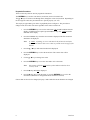
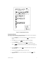
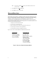
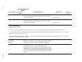
1
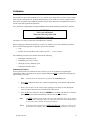
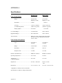
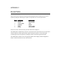
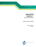
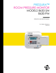
HVAC Controls–Laboratory Model 8610 EVERWATCH® Face Velocity Monitor Operation and Service Manual P/N 1980154, Revision E October 2002 Model 8610 EVERWATCH® Face Velocity Monitor Operation and Service Manual October 2002 P/N 1980154 Rev. E U.S. AND CANADA Sales & Customer Service: (800) 874-2811/(651) 490-2811 Fax: (651) 490-3824 SHIP/MAIL TO: TSI Incorporated ATTN: Customer Service 500 Cardigan Road Shoreview, MN 55126 USA OTHER COUNTRIES Sales & Customer Service: (001 651) 490-2811 Fax: (001 651) 490-3824 E-MAIL [email protected] WEB SITE www.tsi.com Copyright - TSI Incorporated / October 2002 / All rights reserved. Part number 1980154 Rev. E LIMITATION OF WARRANTY AND LIABILITY Seller warrants the goods sold hereunder, under normal use and service as described in the operator's manual, shall be free from defects in workmanship and material for twenty-four (24) months, or the length of time specified in the operator's manual, from the date of shipment to the customer. This warranty period is inclusive of any statutory warranty. This limited warranty is subject to the following exclusions: a. Hot-wire or hot-film sensors used with research anemometers, and certain other components when indicated in specifications, are warranted for 90 days from the date of shipment. b. Parts repaired or replaced as a result of repair services are warranted to be free from defects in workmanship and material, under normal use, for 90 days from the date of shipment. c. Seller does not provide any warranty on finished goods manufactured by others or on any fuses, batteries or other consumable materials. Only the original manufacturer's warranty applies. d. Unless specifically authorized in a separate writing by Seller, Seller makes no warranty with respect to, and shall have no liability in connection with, goods which are incorporated into other products or equipment, or which are modified by any person other than Seller. The foregoing is IN LIEU OF all other warranties and is subject to the LIMITATIONS stated herein. NO OTHER EXPRESS OR IMPLIED WARRANTY OF FITNESS FOR PARTICULAR PURPOSE OR MERCHANTABILITY IS MADE. TO THE EXTENT PERMITTED BY LAW, THE EXCLUSIVE REMEDY OF THE USER OR BUYER, AND THE LIMIT OF SELLER'S LIABILITY FOR ANY AND ALL LOSSES, INJURIES, OR DAMAGES CONCERNING THE GOODS (INCLUDING CLAIMS BASED ON CONTRACT, NEGLIGENCE, TORT, STRICT LIABILITY OR OTHERWISE) SHALL BE THE RETURN OF GOODS TO SELLER AND THE REFUND OF THE PURCHASE PRICE, OR, AT THE OPTION OF SELLER, THE REPAIR OR REPLACEMENT OF THE GOODS. IN NO EVENT SHALL SELLER BE LIABLE FOR ANY SPECIAL, CONSEQUENTIAL OR INCIDENTAL DAMAGES. SELLER SHALL NOT BE RESPONSIBLE FOR INSTALLATION, DISMANTLING OR REINSTALLATION COSTS OR CHARGES. No Action, regardless of form, may be brought against Seller more than 12 months after a cause of action has accrued. The goods returned under warranty to Seller's factory shall be at Buyer's risk of loss, and will be returned, if at all, at Seller's risk of loss. Buyer and all users are deemed to have accepted this LIMITATION OF WARRANTY AND LIABILITY, which contains the complete and exclusive limited warranty of Seller. This LIMITATION OF WARRANTY AND LIABILITY may not be amended, modified or its terms waived, except by writing signed by an Officer of Seller. SERVICE POLICY Knowing that inoperative or defective instruments are as detrimental to TSI as they are to our customers, our service policy is designed to give prompt attention to any problems. If any malfunction is discovered, please contact your nearest sales office or representative, or call TSI's Customer Service department at (800) 874-2811 or (651) 490-2811. ii CONTENTS HOW TO USE THIS MANUAL ...........................................................................................iii PART ONE USER BASICS ............................................................................ 1 The Instrument............................................................................. 1 Operator Panel............................................................................. 1 Alarms .......................................................................................... 3 Before Calling TSI........................................................................ 3 PART TWO TECHNICAL SECTION ............................................................... 5 Software Programming ................................................................ 5 Menu and Menu Items ................................................................. 8 Calibration .................................................................................. 13 Maintenance and Repair Parts .................................................. 14 APPENDIX A SPECIFICATIONS..................................................................... 19 APPENDIX B WIRING DIAGRAM ................................................................... 21 APPENDIX C ACCESS CODES ...................................................................... 22 How to Use This Manual The EVERWATCH Operation and Service Manual describes how to operate, configure, calibrate, maintain and troubleshoot the Model 8610 EVERWATCH Face Velocity Monitor. The manual is divided into two parts. Part one describes the EVERWATCH unit and how to interface with the device. This section should be read by users, facilities staff, and anyone who requires a basic understanding of how the device operates. Part two describes the technical aspects of the product which include operation, configuration, calibration, maintenance and trouble shooting. Part two should be read by personnel programming or maintaining the unit. TSI recommends thoroughly reading this manual before changing any software items. Note: This operation and service manuals assumes that the EVERWATCH has been properly installed. Refer to the Installation Instructions if there is any question as to whether the EVERWATCH has been installed properly. iii Part One User Basics This section provides a brief but thorough overview of the EVERWATCH product by maximizing information with minimal reading. These few pages explain the purpose (The Instrument), and the operation (Useful user information, Operator panel, Alarms) of the product. Technical product information is available in Part Two of the manual. The Instrument The EVERWATCH measures and reports “face velocity” in fume hoods. Adequate face velocity is a key component needed to protect fume hood users. An adequate face velocity contains all the contaminants inside of the fume hood. The fume hood exhaust system produces a pressure differential between the hood interior and the laboratory, causing air to be drawn into the hood. In a properly designed and used fume hood the air drawn into the fume hood is the same everywhere in the sash plane (opening). The speed the air enters the fume hood is called the face velocity. The Model 8610 EVERWATCH Face Velocity Monitor continuously monitors fume hood face velocity by measuring the air velocity across a sensor mounted in the sidewall of the hood. The sensor and opening in the fume hood are driven by the same pressure differential so the velocity across each is related. The EVERWATCH device informs the hood user when the fume hood has an adequate face velocity by indicating the actual face velocity and turning on a green light. If the face velocity is inadequate, or too great, a red alarm light and audible alarm turn on. The EVERWATCH consists of two pieces; a velocity sensor and monitor electronics. The velocity sensor is mounted in the sidewall of the fume hood usually near the top of the sash. The monitor electronics are typically mounted about eye level on the front of the fume hood cabinetry. The velocity sensor continuously measures the face velocity and provides the face velocity information to the monitor electronics. The monitor electronics continuously report the face velocity and activates the alarms when necessary. Useful User Information The monitor electronics has a green light (normal operation) and red alarm light (low and high alarms). The green light is on when the face velocity is adequate. The red low alarm light comes on when the face velocity drops below a safe level. The red high alarm light comes on when the face velocity exceeds a safe level. The display provides additional information by continuously indicating the actual face velocity Operator Panel The EVERWATCH Face Velocity Monitor is easy to use. All the information you need to know about the face velocity is displayed on the monitor's front panel. In addition, all configuration and calibration programming is accessible through the keypad. Specific details about the EVERWATCH front panel display and controls are described on the following pages. The front panel, shown in Figure 1 identifies the important features; display, keys and lights. User Basics 1 Figure 1: EVERWATCH Front Panel Display Digital Display The digital display continuously indicates the face velocity, and if problems with the monitoring system occurs displays error messages. In addition, the display indicates the menu items and menu item values when programming or calibrating the monitor. NORMAL Light / Key The green light (part of NORMAL key) indicates that the face velocity is within the normal (safe) operating range. The normal light is on when the face velocity is between the low alarm set point and the high alarm set point. The NORMAL key is used to gain access to the calibration and configuration menus. Refer to Part two, “Technical Section,” for calibration and configuration instructions. LOW ALARM Light / Key The red low alarm light turns on when the face velocity drops below the low face velocity alarm set point (green normal light goes off). The LOW ALARM key, when pressed, displays the low alarm set point on the digital display. HIGH ALARM Light / Key The red high alarm light turns on when the face velocity exceeds the high face velocity alarm set point (green normal light goes off). The HIGH ALARM key, when pressed, displays the high alarm set point on the digital display. MUTE Light / Key The yellow mute light turns on when the audible alarm has been turned off. The audible alarm will not sound as long as the mute light is on. 2 Part One The MUTE key is used to silence and/or disable the audible alarm. An audible alarm can be silenced at anytime by pressing the MUTE key. Pressing the MUTE key once temporarily mutes the alarm (resets when velocity returns to normal range). Pressing the MUTE key twice turns the yellow mute light on and permanently disables the audible alarm. To turn the audible alarm back on press the MUTE key once. TEST Key The TEST key, when pressed, initiates an instrument self-test. The monitor display, indicator lights, audible alarm, and internal electronics are tested when the TEST key is pressed. RESET Key The RESET key is used to reset the low and high face velocity alarm lights, alarm contacts and audible alarm, when the instrument is configured for alarm latch operation (see ALARM RESET). The alarms are reset only after the face velocity has returned to normal range and the RESET key is pressed. The RESET key is also used to reset error messages. Alarms EVERWATCH has visual (red lights) and audible alarms to inform the user of changing conditions. The alarm levels (set points) are determined by facilities personnel, which could be safety officer, health inspector, etc. The alarms, audible and visual, will activate whenever the preset alarm level is reached. Depending on how the alarms are programmed, they will activate when the face velocity is low or inadequate, high or too great. When the fume hood is operating in the safe range no alarms will sound. Visual Alarm Operation The red low alarm light is on when a low or inadequate face velocity exists. The red high alarm light is on when a high or excessive face velocity exists. Audible Alarm The audible alarm continuously sounds when the face velocity is in an alarm condition. The audible alarm can be temporarily silenced by pressing the MUTE key once, or permanently by pressing the MUTE key twice (yellow light comes on). The audible and visual alarms can be programmed to either automatically turn off when the unit returns to the safe range or to stay in alarm until the RESET key is pressed. (See ALARM RESET). Before Calling TSI The manual should answer most questions and resolve most problems the user may encounter. If you need assistance or further explanation, contact your local TSI representative or TSI. TSI is committed to providing high quality products backed by outstanding service. User Basics 3 Please have the following information available prior to contacting your authorized TSI Manufacturer’s Representative or TSI: ! Model number of unit* ! Software revision level* ! Facility where unit is installed * Found on back of monitor electronics. For the name of your local TSI representative or to talk to TSI service personnel, please call TSI at: U.S. AND CANADA Sales & Customer Service: (800) 874-2811/(651) 490-2811 Fax: (651) 490-3824 SHIP/MAIL TO: TSI Incorporated ATTN: Customer Service 500 Cardigan Road Shoreview, MN 55126 USA 4 OTHER COUNTRIES Sales & Customer Service: (001 651) 490-2811 Fax: (001 651) 490-3824 E-MAIL [email protected] WEB SITE www.tsi.com Part One PART TWO Technical Section The EVERWATCH is ready to use after being properly installed and calibrated. The monitor is programmed with a default configuration that can be easily modified to fit you application. The “Technical” section is separated into five parts that cover all aspects of the units. Each section is written as independently as possible to minimize flipping back and forth through the manual for an answer. The “Software Programming” section explains the programming sequence which is the same regardless of the menu item being changed. At the end of this section is an example of how to program the monitor. The “Menu and Menu Item” sections list all of the software items available to program and change in both the configuration and calibration menus. This section covers menu items and all related information including programming name, description of menu item, range of programmable values, and how the unit is shipped from the factory (default values). The “Calibration” section describes the required technique to calibrate the EVERWATCH unit. This includes how to measure face velocity, check for an adequate face velocity, and zero and span the units. The “Maintenance and Repair Part” sections covers all routine maintenance of equipment, along with a list of repair parts. The “Troubleshooting” section covers both the mechanical operation of the unit and system performance. Many external variables will affect how the unit functions so it is critical to first determine if the unit is having mechanical problems- i.e. no display on unit, remote alarms don’t function, etc. If problems still exist, look for performance problems (i.e., doesn’t’ read correctly, display fluctuates, etc.). The first step is to determine that the system is mechanically operating correctly, followed by modifying the configuration to eliminate the performance problems. Software Programming The EVERWATCH is a quick and easy to program. There are two menus that contain all the items that can be changed. The configuration menu changes items that enhance the monitor’s performance (i.e., alarm values, display averaging, etc.). The calibration menu has the menu items needed to properly calibrate the EVERWATCH. Regardless of the menu item you want to change, the procedure, described below, is the same. This section covers programming the instrument through the keypad and display. If programming through RS-485 communications, use the host computer’s procedure. The changes take place immediately upon saving data in the instrument. Technical Section 5 Keystroke Procedure There are three keys that are used to program the instrument: The NORMAL key is used to enter menus, menu items, and to exit menu items. The ▲ / ▼ keys are used to scroll through menu, change the values of menu items. Depending on the item type the values may be numerical or a specific property (on / off). The step-by-step procedure given below is graphically shown in Figure 2. The procedure to change a menu item value is the same regardless of the menu or menu item. 1. Press the NORMAL key to access the main menu. CAL should be indicated on the display. If CONF menu is required, press the ▼ arrow key once. CONF should be indicated on the display. 2. Press the NORMAL key when the correct menu is displayed. The first menu item should now be displayed. Note: If “COdE” is flashing, an access code must be keyed into the unit before access will be allowed. The access codes are printed on the last page of the manual. 3. Press the ▲ / ▼ keys until menu item desired is displayed. 4. Press the NORMAL key to select the menu item. The current value will be displayed. 5. Use the ▲ / ▼ keys to change item value. 6. Press the NORMAL key to save the value and to exit to the menu. Note: The monitor will flash SAVE and beep which indicates data has been correctly saved. 7. Press the ▼ key until End is displayed. 8. Press the ▼ key once to exit the menu, or press the NORMAL key to exit to the main menu (calibration or configuration menu can then be selected). If more than one item is to be changed, skip step 7 and 8 until all items in that menu are changed. 6 Part Two Figure 2: Programming Flow Chart Programming Example The following example demonstrates the programming keystroke sequence. In this example the face velocity low alarm will be programmed for 60 ft/min. 1. Press the NORMAL key to access the main menu. CAL will be indicated on the display. 2. Press the ▼ arrow key once. CONF should be indicated on the display. 3. Press the NORMAL key. The first menu item (LAL) is now displayed. Note: If “COdE” is flashing an access code must be keyed into the unit before access will be allowed. The access codes are printed on the last page of the manual. 4. Press the NORMAL key to select LAL (low alarm menu item). The current value will be displayed. 5. Press the arrow keys ▲ / ▼ to change the item value to 60. 6. Press the NORMAL key to save the value and to exit to the menu. LAL will be displayed. Technical Section 7 Note: The monitor will flash SAVE and beep which indicates data has been correctly saved. 7. Press the ▼ arrow until End is displayed. 8. Press the ▼ key once to exit the menu. Menu and Menu Items The EVERWATCH has two menus: a configuration (CONF) menu and a calibration (CAL) menu. All the software programming takes place inside of these two menus. The configuration menu allows you to tailor the unit to your specific application. The calibration menu is only used when calibration is required. Changing any item is accomplished by using the keypad, or if communications are installed through the RS-485 Communications port. If you are unfamiliar with the keystroke procedure please see “Programming Software” for a detailed explanation. This section provides the following information: ! Complete list of menu and all menu items ! Gives the menu or programming name ! Defines each menu items’ function: what it does, how it does it, etc. ! Gives the range of values that can be programmed. ! Gives default item value (how it shipped from factory). Figure 3 shows a chart of all the Model 8610 standard monitor menu items. CALIBRATION CONFIGURATION Calibration zero (LCAL) Calibration Span (HCAL) Access Code (PASS) Calibration End (End) Low Alarm (L_AL) High Alarm (H_AL) Display Filtering Period (dSPL) Alarm Reset (ALr) Alarm Disable (dSbL) Analog Output (AOUt) RS-485 Type (PrOt) RS-485 Address (Addr) Access Code (PASS) Configuration End (End) Figure 3: Menu Items - Model 8610 Standard Monitor 8 Part Two Technical Section CALIBRATION MENU MENU ITEM CALIBRATION ZERO SOFTWARE NAME LCAL ITEM DESCRIPTION The velocity CALIBRATION ZERO item is used to calibrate the EVERWATCH velocity sensor at zero flow. ITEM RANGE NONE A sensor zero should be established prior to adjusting the sensor span (see “Calibration” section following menu item section). CALIBRATION SPAN HCAL The velocity CALIBRATION SPAN item is used to calibrate the EVERWATCH velocity sensor to the average face velocity as measured by a portable air velocity meter. NONE DEFAULT VALUE Unit needs to be calibrated. No default value exists. Unit needs to be calibrated. No default value exists. A sensor zero should be established prior to adjusting the sensor span (see “Calibration” section following menu item section). ACCESS CODE PASS The PASS item selects whether an access code is required to enter the calibration menu. If the access code is ON a code is required before the menu can be entered. Conversely if the access code is OFF no code is required to enter the menu. ON or OFF OFF CALIBRATION MENU END End The End item identifies that the end of the calibration menu has been reached. NONE This is not a menu item. This identifies that the end of the menu has been reached. 9 10 CONFIGURATION MENU MENU ITEM LOW ALARM HIGH ALARM SOFTWARE NAME L_AL H_AL ITEM DESCRIPTION ITEM RANGE The LOW ALARM item sets the low face velocity alarm setpoint. A low alarm condition is defined as when the face velocity falls below the low alarm setpoint. Off, 5–1000 ft/min The HIGH ALARM item sets the high face velocity alarm setpoint. A high alarm condition is defined as when the face velocity is greater than the high alarm setpoint. Off, 40–1000 ft/min DEFAULT VALUE 60 Off, 0.02–5.0 m/s 140 Off, 0.2–5.0 m/s ALARM CONSTRAINTS The alarms operate as follows: 1. There is a five second delay between the time an alarm occurs and the time that the alarms lights, audible alarm and alarm relays activate. 2. Low alarm. The low alarm activates when the velocity drops below the low alarm setpoint. The low alarm stays on until the face velocity rises 20 ft/min (0.1 m/s) above the low alarm set point. 3. High alarm. The high alarm activates when the velocity exceeds the high alarm setpoint. The high alarm stays on until the face velocity drops 20 ft/min (0.1 m/s) below the high alarm set point. DISPLAY FILTERING PERIOD DSPL The dSPL item is the period of time over which the face velocity readings are averaged before being displayed. The longer the display averaging period, the more stable (less fluctuation) the display. ALARM RESET Alr The ALr item selects how the alarms terminate after the unit returns to the safe (normal) velocity range. UNLATCHED (UnLA) automatically resets the alarms when the unit reaches the safe range. LATCHED (LA) requires the staff to press the RESET key after the unit returns to the safe range. The ALARM RESET affects the audible alarm, visual alarm, and relay outputs, which means all are latched or unlatched. 1-20 seconds 5 seconds Latched or Unlatched Latched (LA) Part Two Technical Section ALARM DISABLE DSBL The dSBL item selects whether the audible alarm can be permanently muted (on) or cannot (off) by pressing the MUTE key (yellow light on). On or Off On ANALOG OUTPUT AOUt The AOut item is used to select the type of analog output. The analog output signal can be either 0-10 VDC (VOLt) or 4-20 mA (CUrr). 0–10 volt (VOLt) or 4–20 mA (CUrr) VoLt Modbus (0) or Cimetrics (1) Modbus (0) 1–247 1 ON or OFF OFF The EVERWATCH has a selectable linear analog output (0 to 10 volt or 4 to 20 mA) which corresponds to the measured (real-time) face velocity. The analog output has a velocity range between 0 and 1000 ft/min (0 to 5.00 m/s). With this range, a 100 ft/min (.51 m/s) equals an output of 1 volt (5.6 mA), and a 1000 ft/min (5.00 m/s) equals an output of 10 volts (20 mA). RS-485 TYPE PrOt The Prot item selects the communications protocol used to interface with the building management system. Contact TSI if further information is needed regarding interfacing the monitor to the building automation system through RS-485 communications. RS-485 ADDRESS Addr The Addr item selects the main network address of the individual fume hood monitor. Each unit on the network must have a unique address. There is no priority between the RS-485 and keypad. The most recent signal either RS-485 or keypad will initiate a change. RS-485 communication allows the user to access all items except calibrations items. ACCESS CODE PASS The PASS item selects whether an access code is required to enter the calibration menu. If the access code is ON a code is required before the menu can be entered. Conversely if the access code is OFF no code is required to enter the menu. 11 12 CALIBRATION MENU END End The End item identifies that the end of the calibration menu has been reached. NONE This is not a menu item. This identifies that the end of the menu has been reached. Part Two Calibration The EVERWATCH Face Velocity Monitor is a very versatile device which will work with a variety of fume hoods. Because fume hoods vary in design and performance, the EVERWATCH must be calibrated on the fume hood it is installed. The calibration procedure is quite simple and can be accomplished in a matter of minutes with a little preparation and practice. Every EVERWATCH shipped has an orange WARNING label attached indicating calibration is required: WARNING: Unit is not calibrated. Remove label only after field calibration is complete. This label is to be removed only after field calibration is complete. Before beginning to calibrate the EVERWATCH, take a few minutes to review the calibration procedures below. The following equipment is required to perform the calibration: ! Tape ! Portable Air Velocity Meter such as TSI VELOCICALC or VELOCICHECK The calibration procedure can be broken down into the following: ! Entering the calibration menu. ! Establishing a zero flow velocity. ! Setting the velocity calibration span. ! Exiting the calibration menu. Calibration Procedure Power up the EVERWATCH and allow the unit to warm up (30 to 60 seconds) before beginning the calibration procedure. On initial power up the keypad is disabled and SEnS is indicated on the display for approximately 30 seconds. Note: All menu items described below are found in the Calibration menu. 1. Select CAL (calibration menu). See “Software Programming” if not familiar with keystroke procedure. 2. Place a piece of tape over the velocity sensor opening to seal off the air flow through the sensor (off white colored sensor is located inside of fume hood). 3. Select LCAL (zero calibration). Press the NORMAL key and CAL will flash for two minutes. During this time the monitor automatically calibrates the sensor for zero flow. Note: If COdE is flashing on the display, the access code enable function is set to on and an access code is required to enter the calibration menu. Enter the calibration menu access code (code is located on last page of manual). Note 2: If the sensor has not been taped, "tAPE OVEr SEn SOr" ("tape over sensor") will be indicated on the display. This message will flash for approximately two minutes. Technical Section 13 If the sensor has not been taped by the end of this time period, the calibration menu is exited and the EVERWATCH returns to normal operation. 4. CAL stops flashing and the audible alarm sounds momentarily when sensor zero is complete. 5. Remove the tape from the velocity sensor. 6. Press the ▼ key once. Confirm that HCAL is indicated on the display. Note: Always take a sensor zero prior to adjusting the zero span. 7. Open the sash to 60 percent of the full open position. 8. Use a portable air velocity meter to traverse the open sash area and obtain the average face velocity of the air passing into the hood. Note: 9. If you are unfamiliar with traversing fume hoods, an excellent reference is available that covers in detail traversing fume hoods. The reference is ASHRAE 110-1995 Method of Testing Performance of Laboratory Fume Hoods, section 6.2 face velocity measurements. Press the NORMAL key to indicate the current face velocity. Note: On initial calibration, the keypad is disabled and SEnS flashes on and off for approximately 30 seconds while the sensor stabilizes. 10. Compare the face velocity indicated on the EVERWATCH display to the face velocity measured by the portable air velocity meter. Use the ▲ / ▼ keys to adjust the EVERWATCH face velocity until it matches the face velocity measured by the portable air velocity meter. 11. Press the NORMAL key to save the calibration span data. HCAL is indicated on the display. 12. Press the ▼ key until End is indicated. Unit automatically returns to normal operation. 13. Press the ▼ key once to exit the calibration menu. 14. Verify calibration of EVERWATCH matches the portable air velocity meter. Calibrating the span on the EVERWATCH may be an iterative process that takes one to three trials to set an accurate calibration. The user must check the span after each trial until an accurate calibration is achieved. Note: The EVERWATCH automatically exits the calibration menu and returns to normal operation if more than five minutes elapse between keystrokes. All changes to the calibration menu values are automatically saved. Maintenance and Repair Parts The EVERWATCH is almost maintenance free. An occasional sensor cleaning and periodic calibration checks are all that are needed to insure that the EVERWATCH is operating at optimum performance. 14 Part Two Calibration EVERWATCH should be calibrated annually. Refer to “Calibration” section instructions. The velocity sensor should be cleaned prior to calibration. Velocity Sensor Cleaning Significant build-up of dust or dirt on the velocity sensor can degrade its performance. It is recommended that the velocity sensor be periodically inspected for accumulation of contaminants. The frequency of these inspections is dependent upon the quality of the room air drawn across the sensor. Quite simply, if the air in the room is dirty, the sensor will require more frequent examinations and cleaning. Caution: Turn power to EVERWATCH off prior to cleaning the velocity sensor. Do not use compressed air to clean the velocity sensor. Accumulations of dust or dirt can be removed with a soft-bristled brush (such as an artist's brush). Alcohol, acetone, or trichlorethane may be used as a solvent to remove other contaminants if required. WARNING: Do not attempt to scrape contaminants from the velocity sensor. The velocity sensors are quite durable, however scraping will cause mechanical damage and possibly break the sensor. Mechanical damage due to scraping voids the velocity sensor warranty. Replacement Parts All components of the EVERWATCH are field replaceable. Contact TSI at (651) 490-2811 or your nearest authorized TSI manufacturer's representative for replacement part pricing and delivery. Technical Section Part Number Description 800320 800325 800515 800516 800420 800414 Velocity Sensor Sensor Cable Velocity Monitor, English Velocity Monitor, Metric Transformer Transformer Cable 15 Troubleshooting Chart Symptom Display is blank. Possible Cause Fuse is blown. Corrective Action Measure voltage at pins 1 and 2 on monitor. The voltage should nominally be 24–30 VAC. If correct voltage is measured, internal monitor fuse is probably blown. Unplug 10-pin connector from monitor for 2 minutes. The internal fuse will automatically reset. Plug unit back in and check display. If display is still blank, check all wiring, etc. If no problems are found, replace monitor. If zero volts are measured, see No power to monitor. Wiring is incorrect. Check all wiring. If separate transformer is not installed for each system, double check polarity and for ground loops. Alarm relays don't work. "dATA Err" flashing on display. 16 No power to monitor. Verify circuit breaker is on. Verify transformer primary measures 110 VAC. Verify transformer secondary measures 24–30 VAC. Verify voltage on pins 1 and 2 of monitor is 24–30 VAC. Monitor is defective. If proper voltage is found between pins 1 and 2 of the monitor, all wiring has been checked, fuses have been reset, and screen is still blank, the monitor is probably defective. Replace monitor. Alarms are turned off. Press LOW or HIGH alarm key. The individual alarm set points will display. If all alarm set points are zero, alarm relay is not active, so relay will not be required to change state. Incorrect wiring. Check the wiring from EVERWATCH relay's output to the device that is connected to the relay. Relay may be defective. Disconnect the wiring from relay contact pins 7 and 8 for low alarm relay and pins 3 and 4 for high alarm relay. Connect an ohmmeter to relay terminals to verify contact open and closes. Activate the alarm to manually trip the relay. (This may require opening or closing sash). If relay responds (contact opens and closes), the device connected is incompatible or defective. If relay doesn’t respond, relay is defective (may be caused by incompatible device). Replace monitor. Monitor was hit by electrical disturbance. All data may be lost or changed. Review all configuration parameters. dATA Err is removed by pressing the RESET key. Part Two Symptom The display does not indicate zero at zero flow. The display fluctuates. Possible Cause Velocity sensor. Corrective Action Check velocity sensor location. Make sure it matches installation instructions. The sensor should directly reference room air. If required, mount a fume hood vent kit. Calibration required. The EVERWATCH must be calibrated when installed or moved. Calibration. The span may be incorrectly adusted. Room turbulence. Check and adjust the display averaging period. Check the effects of the room air distribution system on the EVERWATCH. ❶ Turn the hood off. ❷ Measure the air velocity at hood face. ❸ Measure the air velocity at the velocity sensor. The terminal throw velocity of a diffuser at the hood face should be less than 50% of the average hood face velocity. The terminal throw velocity at the velocity sensor should be less than 10 ft/min (0.04 m/s). For example, if the hood is running at 100 ft/min the terminal throw velocity at the hood face should be less than 50 ft/min. The lower the terminal flow velocity, the better. If the terminal throw velocity of a diffuser exceeds the values listed above, move or readjust the diffuser. The indicated face velocity and the average face velocity are not the same. Sensor is dirty. Check cleanliness of the velocity sensor. Remove all contaminants. Check the velocity sensor for obstructions. Remove any obstructions. Calibration is off. Calibrate the EVERWATCH. The analog output doesn’t display correctly. Incorrect output selected. Check that correct output is selected. VOLt selects a 0–10V output. CUrr selects a 4–20 mA output. "SEnS Err" is indicated on the display. Velocity is too high. Velocity exceeded 1500 ft/min. Adjust fan speed or balancing damper. Possible bad sensor or sensor cable. Check the sensor wiring and connections for continuity. Replace the velocity sensor and/or sensor to monitor cable and calibrate the EVERWATCH. Technical Section 17 Symptom Monitor does not respond to RS-485 communications. 18 Possible Cause Network protocol is incorrect. Corrective Action Go into CONFIGURE menu, RS-485 type item. The protocol must match host system. Select correct interface. Incorrect network address. The network address at the building automation system and at the monitor must match. The network address must be unique for each monitor. Incompatible software. Data sent to monitor may be in form that the EVERWATCH cannot recognize. Part Two APPENDIX A Specifications Model 8610 English Units Model 8610 Metric Units Face Velocity Display Range ..................................................... 0-1000 ft/min (displays to 1500) Resolution .............................................. 5 ft/min Accuracy ............................................... ±10% or ±10 ft/min (at calibrated position) (whatever is greater) Display Update....................................... 0.5 second 0 to 5.00 m/s (displays to 7.60) 0.02 m/s ±10% or ±0.05 m/s (whatever is greater) 0.5 second Low Alarm Range* .............................................. 5 to 1000 ft/min 0.02 to 5.00 m/s High Alarm Range* ............................................. 40 to 1000 ft/min 0.20 to 5.00 m/s Alarm Contacts..................................................... SPST (N.O.) max current 5 amps, max voltage 150 VDC, 250 VAC. Minimum switch load 10 mA, 5 VDC. Face Velocity Analog Output Type ....................................................... 0–10 VDC or 4–20 mA 0–10 VDC or 4–20 mA Range ..................................................... 0–1000 ft/min 0–5.00 m/s Resolution .............................................. 5 ft/min 0.02 m/s Response Time....................................... 1 second 1 second RS-485 Communications ..................................... Modbus or Cimetrics Modbus or Cimetrics Operating Temperature ........................................ 32 to 120°F 0 to 50°C Temperature ......................................................... 55 to 95°F Compensated Range 13 to 35°C Input Power .......................................................... 24 VAC, 5 watts max 24 VAC, 5 watts max Dimensions........................................................... 5 in. x 3.125 in. x 1 in. 12.7 cm x 7.9 cm x 2.5 cm *Adjustable in 5 ft/min (0.02 m/s) increments. Specifications are subject to change without notice. Appendix A 19 APPENDIX B Wiring Diagram TSI INCORPORATED MAIL/SHIP TO: 500 CARDIGAN ROAD SHOREVIEW, MN 55126 TELEPHONE: 651-490-2811 FAX: 651-490-3824 Appendix B 21 APPENDIX C Access Codes These are the access codes to the calibration and configuration menus. When an access code is required, pressing the following key sequence will provide access to the required menu. Key # Calibration Configuration 1 2 3 4 5 RESET LOW ALARM NORMAL TEST RESET LOW ALARM TEST RESET HIGH ALARM LOW ALARM If the access code is entered correctly, the first menu item is displayed. The audible alarm sounds briefly each time a keystroke has been entered. The access code must be entered within 40 seconds (approximately eight seconds per keystroke). If more than eight seconds elapses between keystrokes, the monitor returns to the normal operational mode. The audible alarm sounds, an error message (Err) flashes on the display, and the configuration menu is exited if an incorrect access code in entered. TSI Incorporated 500 Cardigan Road, Shoreview, MN 55126 U.S.A. Web: www.tsi.com