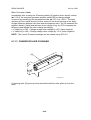
1
Model S-C1
(Machine Code: B045/B049/B044/B046)
SERVICE MANUAL
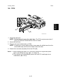
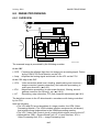
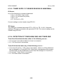
B046I100.WMF
17 July, 2001
Subject to change
!IMPORTANT SAFETY NOTICES
PREVENTION OF PHYSICAL INJURY
1. Be sure that the power cord is unplugged before disassembling or
assembling parts of the copier or peripherals.
2. The wall outlet should be near the copier and easily accessible.
3. Note that electrical voltage is supplied to some components of the copier
and the paper tray unit even while the main power switch is off.
4. If you start a job before the copier completes the warm-up or initializing
period, keep hands away from the mechanical and electrical components
until job execution has started. The copier will start making copies as soon
as warm-up or initialization is finished.
5. The inside and the metal parts of the fusing unit become extremely hot while
the copier is operating. Be careful to avoid touching those components with
your bare hands.
HEALTH SAFETY CONDITIONS
Toner and developer are nontoxic, but getting either of these into your eyes may
cause temporary eye discomfort. Try to remove with eye drops or flush with
water. If material remains in eye or if discomfort continues, get medical attention.
OBSERVANCE OF ELECTRICAL SAFETY STANDARDS
The copier and its peripherals must be installed and maintained by a customer
service representative who has completed the training course on those relevant
models.
LITHIUM BATTERIES
Incorrect replacement of lithium battery(s) on the FCU may pose risk of
explosion. Replace only with the same type or with an equivalent type
recommended by the manufacturer. Discard used batteries in accordance with
the manufacturer’s instructions.
SAFE AND ECOLOGICAL DISPOSAL
1. Do not incinerate toner bottles or used toner. Toner dust may ignite suddenly
if exposed to an open flame.
2. Dispose of used toner, developer, and organic photoconductors in
accordance with local regulations. (These are nontoxic supplies.)
3. Dispose of replaced parts in accordance with local regulations.
1
LASER SAFETY
The Center for Devices and Radiological Health (CDRH) prohibits the repair of
laser-based optical units in the field. The optical housing unit can only be repaired
in a factory or at a location with the requisite equipment. The laser subsystem is
replaceable in the field by a qualified Customer Engineer. The laser chassis is not
repairable in the field. Customer engineers are therefore directed to return all
chassis and laser subsystems to the factory or service depot when replacement of
the optical subsystem is required.
!WARNING
Use of controls not specified in this manual, or performance of
adjustments or procedures not specified in this manual, may result in
hazardous radiation exposure.
!WARNING FOR LASER UNIT
WARNING: Turn off the main switch before attempting any of the
procedures in the Laser Unit section. Laser beams can cause
serious damage to eyes.
CAUTION MARKING:
Symbols and Abbreviations
This manual uses the symbols and abbreviations shown below.
Symbol
☛
!
"
#
SEF
LEF
$
Meaning
"See," "Refer to"
Clip ring
Screw
Connector
Short Edge Feed
Long Edge Feed
Core Technology manual
2
TABLE OF CONTENTS
1 INSTALLATION ........................................................................... 1-1
1.1 INSTALLATION REQUIREMENTS ...........................................................1-1
1.1.1 ENVIRONMENT ...............................................................................1-1
1.1.2 MACHINE LEVEL .............................................................................1-2
1.1.3 MINIMUM OPERATIONAL SPACE REQUIREMENTS ....................1-2
1.1.4 POWER REQUIREMENTS ..............................................................1-3
1.2 COPIER.....................................................................................................1-4
1.2.1 ACCESSORY CHECK......................................................................1-4
1.2.2 INSTALLATION PROCEDURE ........................................................1-4
Initial Programming: Faxless models (B044, B045) .............................1-8
Initial Programming: Fax-equipped models (B046, B049)....................1-8
1.3 PAPER TRAY UNIT ................................................................................1-10
1.3.1 ACCESSORY CHECK....................................................................1-10
1.3.2 INSTALLATION PROCEDURE ......................................................1-10
1.4 PAPER TRAY UNIT HEATER .................................................................1-12
1.4.1 ACCESSORY CHECK....................................................................1-12
1.4.2 INSTALLATION PROCEDURE ......................................................1-12
1.5 DOCUMENT FEEDER ............................................................................1-17
1.5.1 ACCESSORY CHECK....................................................................1-17
1.5.2 INSTALLATION PROCEDURE ......................................................1-17
1.6 DIMM.......................................................................................................1-21
1.6.1 INSTALLATION PROCEDURE ......................................................1-21
2 PREVENTIVE MAINTENANCE SCHEDULES ............................. 2-1
2.1 PM TABLES ..............................................................................................2-1
2.2 HOW TO CLEAR THE PM COUNTER......................................................2-2
3 REPLACEMENT AND ADJUSTMENT......................................... 3-1
3.1 PRECAUTIONS.........................................................................................3-1
3.1.1 GENERAL ........................................................................................3-1
3.1.2 LITHIUM BATTERIES ......................................................................3-1
3.1.3 PCU (PHOTOCONDUCTOR UNIT) .................................................3-1
3.1.4 TRANSFER ROLLER .......................................................................3-1
3.1.5 SCANNER UNIT...............................................................................3-2
3.1.6 LASER UNIT ....................................................................................3-2
3.1.7 FUSING UNIT...................................................................................3-2
3.1.8 PAPER FEED...................................................................................3-2
3.1.9 IMPORTANT ....................................................................................3-3
3.2 SPECIAL TOOLS AND LUBRICANTS ......................................................3-3
3.3 EXTERIOR COVER AND OPERATION PANEL .......................................3-4
3.3.1 PLATEN COVER ..............................................................................3-4
3.3.2 REAR COVER..................................................................................3-4
3.3.3 COPY TRAY.....................................................................................3-5
3.3.4 SCALE PLATE (B044 AND B045 ONLY) .........................................3-5
3.3.5 LEFT COVER ...................................................................................3-6
i
3.3.6 RIGHT COVER.................................................................................3-6
3.3.7 FRONT LEFT COVER AND OPERATION PANEL ..........................3-6
3.3.8 FRONT RIGHT COVER ...................................................................3-6
3.3.9 RIGHT DOOR...................................................................................3-7
3.3.10 BYPASS TRAY (B044 AND B046 ONLY) ......................................3-7
3.3.11 PLATEN COVER SENSOR............................................................3-8
3.4 SCANNER SECTION ................................................................................3-9
3.4.1 EXPOSURE GLASS.........................................................................3-9
Non-DF machines.................................................................................3-9
DF-equipped machines.........................................................................3-9
3.4.2 LENS BLOCK .................................................................................3-10
3.4.3 EXPOSURE LAMP, LAMP STABILIZER BOARD ..........................3-10
3.4.4 SCANNER MOTOR........................................................................3-11
3.4.5 SCANNER HP SENSOR ................................................................3-11
3.4.6 SCANNER ALIGNMENT ADJUSTMENT .......................................3-12
3.5 FUSING ...................................................................................................3-13
3.5.1 FUSING UNIT.................................................................................3-13
3.5.2 EXIT SENSOR ...............................................................................3-13
3.5.3 HOT ROLLER STRIPPER PAWLS ................................................3-14
3.5.4 HOT ROLLER & FUSING LAMP ....................................................3-15
3.5.5 THERMOFUSE, THERMOSWITCH, AND THERMISTOR.............3-15
3.5.6 PRESSURE ROLLER.....................................................................3-16
3.6 PCU.........................................................................................................3-17
3.7 TONER SUPPLY CLUTCH .....................................................................3-18
3.8 PAPER FEED SECTION.........................................................................3-19
3.8.1 PAPER FEED ROLLER AND FRICTION PAD...............................3-19
3.8.2 PAPER END SENSOR...................................................................3-19
3.8.3 REGISTRATION SENSOR.............................................................3-20
3.8.4 BYPASS PAPER END SENSOR (B044 AND B046 ONLY) ...........3-20
3.8.5 BYPASS FEED ROLLER (B044 AND B046 ONLY) .......................3-21
3.8.6 BYPASS FEED CLUTCH (B044 AND B046 ONLY) .......................3-22
3.8.7 BYPASS FRICTION PAD (B044 AND B046 ONLY).......................3-22
3.8.8 REGISTRATION CLUTCH .............................................................3-22
3.8.9 PAPER FEED CLUTCH .................................................................3-23
3.9 IMAGE TRANSFER.................................................................................3-24
3.9.1 IMAGE TRANSFER ROLLER ........................................................3-24
3.9.2 ID (IMAGE DENSITY) SENSOR ....................................................3-24
3.9.3 DISCHARGE PLATE ......................................................................3-25
3.10 FUNCTION CONTROL UNIT (FCU) .....................................................3-25
3.11 LASER UNIT .........................................................................................3-27
3.11.1 LOCATION OF “CAUTION” DECAL ............................................3-27
3.11.2 PSU BRACKET ............................................................................3-28
3.11.3 LASER UNIT ................................................................................3-29
3.11.4 LD UNIT........................................................................................3-29
3.11.5 POLYGON MIRROR MOTOR ......................................................3-29
ii
3.12 OTHER REPLACEMENTS....................................................................3-30
3.12.1 QUENCHING LAMP .....................................................................3-30
3.12.2 HIGH-VOLTAGE POWER SUPPLY BOARD ...............................3-30
3.12.3 PSU ..............................................................................................3-30
3.12.4 MAIN MOTOR ..............................................................................3-31
3.12.5 EXHAUST FAN ............................................................................3-31
3.13 COPY IMAGE ADJUSTMENTS: PRINTING/SCANNING .....................3-32
3.13.1 PRINTING ....................................................................................3-32
Registration - Leading Edge/Side-to-Side...........................................3-32
Blank Margin.......................................................................................3-33
Main-Scan Magnification.....................................................................3-33
3.13.2 SCANNING...................................................................................3-34
Registration: Platen Mode...................................................................3-34
Magnification.......................................................................................3-34
Standard White Density Adjustment ...................................................3-35
3.13.3 DF IMAGE ADJUSTMENT ...........................................................3-36
Registration and Blank Margin............................................................3-36
Sub-scan Magnification.......................................................................3-36
4 TROUBLESHOOTING ................................................................. 4-1
4.1 SERVICE CALL CONDITIONS .................................................................4-1
4.1.1 SUMMARY .......................................................................................4-1
4.1.2 SC CODE DESCRIPTIONS .............................................................4-2
4.2 ELECTRICAL COMPONENT DEFECTS ..................................................4-7
4.2.1 SENSOR/SWITCH OPEN ERRORS ................................................4-7
4.3 BLOWN FUSE CONDITIONS ...................................................................4-7
4.4 DUMPING THE FUSER TEMPERATURE LOG........................................4-8
5 SERVICE TABLES....................................................................... 5-1
5.1 USING SERVICE PROGRAM MODE .......................................................5-1
Accessing SP Mode..............................................................................5-1
Accessing Copy Mode from within SP Mode ........................................5-1
How to Select a Program Number ........................................................5-2
To Input a Value or Setting ...................................................................5-2
5.1.1 SP MODE TABLES ..........................................................................5-3
SP1-XXX (Feed) ...................................................................................5-3
SP2-XXX (Drum)...................................................................................5-4
SP4-XXX (Scanner) ..............................................................................5-9
SP5-XXX (Mode) ................................................................................5-14
SP6-XXX (Peripherals) .......................................................................5-18
SP7-XXX (Data Log)...........................................................................5-19
5.1.2 TEST PATTERN PRINTING (SP5-902) .........................................5-23
5.1.3 INPUT CHECK (SP5-803) ..............................................................5-24
Input Check Table...............................................................................5-24
5.1.4 OUTPUT CHECK (SP5-804) ..........................................................5-25
Input Check Table...............................................................................5-25
5.1.5 SMC PRINTING (SP5-992) ............................................................5-26
5.1.6 MEMORY ALL CLEAR (SP5-801) ..................................................5-27
5.1.7 FREE RUNS...................................................................................5-28
iii
5.1.8 PROGRAM UPLOAD/DOWNLOAD ...............................................5-29
Program Download (SP5-827)............................................................5-29
Program Upload (SP5-826) ................................................................5-31
5.1.9 SRAM DATA UPLOAD/DOWNLOAD .............................................5-32
SRAM Data Upload (SP5-824) ...........................................................5-32
SRAM Data Download (SP5-825).......................................................5-33
5.1.10 SERIAL NUMBER INPUT (SP5-811) ...........................................5-33
5.1.11 ID SENSOR ERROR ANALYSIS (SP2-221) ................................5-34
5.1.12 MEMORY READ/WRITE ..............................................................5-35
5.2 USER TOOLS .........................................................................................5-36
5.2.1 HOW TO ENTER AND EXIT USER TOOLS ..................................5-36
5.2.2 USER TOOLS TABLE ....................................................................5-36
System Settings Table ........................................................................5-36
Copy Features Table ..........................................................................5-36
6 DETAILED SECTION DESCRIPTIONS ....................................... 6-1
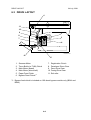
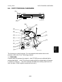
6.1 OVERVIEW ...............................................................................................6-1
6.1.1 COMPONENT LAYOUT ...................................................................6-1
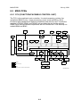
6.2 PAPER PATH............................................................................................6-5
6.3 DRIVE LAYOUT ........................................................................................6-6
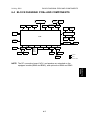
6.4 BLOCK DIAGRAM: PCBS AND COMPONENTS......................................6-7
6.5 MAIN PCBS...............................................................................................6-8
6.5.1 FCU (FUNCTION/FACSIMILE CONTROL UNIT).............................6-8
SPC2 ....................................................................................................6-9
VPL (Video Processing LSI) .................................................................6-9
CIOP (Communications and I/O Processing)........................................6-9
FROM (Flash ROM) – 2MB ..................................................................6-9
DRAM – 8MB.......................................................................................6-9
SRAM – 128K .......................................................................................6-9
3V/5V Converter ...................................................................................6-9
Energy-Save Switching.........................................................................6-9
Reset/Backup Circuit ..........................................................................6-10
SAF Backup........................................................................................6-10
Analog Processing Circuit...................................................................6-10
Modem................................................................................................6-10
Speaker Driver ....................................................................................6-10
Heater Control ....................................................................................6-10
Video Processing Circuit.....................................................................6-10
Power Pack Control ............................................................................6-10
Scanner Driver ....................................................................................6-10
Plotter Driver.......................................................................................6-10
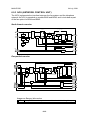
6.5.2 SBU (SENSOR BOARD UNIT).......................................................6-11
Buffer ..................................................................................................6-11
CCD ....................................................................................................6-11
Amplifier..............................................................................................6-11
6.5.3 NCU (NETWORK CONTROL UNIT) ..............................................6-12
North America version ........................................................................6-12
Europe/Asia version............................................................................6-12
iv
6.6 COPY PROCESS OVERVIEW ...............................................................6-13
6.7 SCANNING..............................................................................................6-15
6.7.1 OVERVIEW ....................................................................................6-15
6.7.2 SCANNER DRIVE ..........................................................................6-16
6.8 IMAGE PROCESSING ............................................................................6-17
6.8.1 OVERVIEW ....................................................................................6-17
6.8.2 IMAGE PROCESSING PATH.........................................................6-18
6.8.3 ORIGINAL MODES ........................................................................6-19
Original Modes: Copying....................................................................6-20
6.8.4 IMAGE PROCESSING STEPS FOR EACH MODE .......................6-21
6.8.5 MODE ADJUSTMENTS .................................................................6-22
To customize... ...................................................................................6-22
Default plotter customization settings for each mode... ......................6-23
6.9 LASER EXPOSURE................................................................................6-24
6.9.1 OVERVIEW ....................................................................................6-24
6.9.2 LD SAFETY SWITCHES ................................................................6-25
6.10 PHOTOCONDUCTOR UNIT (PCU) ......................................................6-26
6.10.1 OVERVIEW ..................................................................................6-26
6.10.2 DRUM DRIVE ...............................................................................6-27
6.11 DRUM CHARGE ...................................................................................6-28
6.11.1 OVERVIEW ..................................................................................6-28
6.11.2 CHARGE ROLLER VOLTAGE CORRECTION ............................6-29
Correction for Ambient Environment ...................................................6-29
6.11.3 CHARGE ROLLER CLEANING....................................................6-30
6.11.4 DETECTION OF A NEW PCU......................................................6-31
At time of copier installation ................................................................6-31
When a replacement PCU is installed.................................................6-31
6.12 DEVELOPMENT ...................................................................................6-32
6.12.1 OVERVIEW ..................................................................................6-32
6.12.2 DEVELOPMENT BIAS .................................................................6-33
6.12.3 TONER SUPPLY ..........................................................................6-34
Toner-Bottle Models (B044 and B046)................................................6-34
Toner Hopper Magazine (B045 and B049) .........................................6-35
6.12.4 TONER DENSITY CONTROL ......................................................6-36
Overview.............................................................................................6-36
Reference Voltage ..............................................................................6-36
Toner Density Sensor Initial Setting....................................................6-36
Toner Concentration Measurement ....................................................6-37
Vsp/Vsg Detection ..............................................................................6-37
Calculation of Vref ..............................................................................6-37
Toner Supply Determination ...............................................................6-37
Toner Clutch ON Time ........................................................................6-37
6.12.5 TONER SUPPLY IF SENSOR READING IS ABNORMAL ...........6-38
ID Sensor............................................................................................6-38
TD Sensor...........................................................................................6-38
v
6.12.6 DETECTION OF TONER NEAR END AND TONER END ...........6-38
Toner Near End detected when either of the following occurs............6-38
Toner End detected when any of the following occurs........................6-38
6.13 DRUM CLEANING AND TONER RECYCLING.....................................6-39
6.14 PAPER FEED........................................................................................6-40
6.14.1 OVERVIEW ..................................................................................6-40
6.14.2 PAPER FEED DRIVE MECHANISM ............................................6-41
From Paper Tray.................................................................................6-41
From 100-Sheet Bypass Tray (B044, B046) .......................................6-41
From 1-Sheet Bypass Tray (B045, B049) ...........................................6-41
6.14.3 PAPER FEED AND SEPARATION ..............................................6-42
6.14.4 PAPER LIFT MECHANISM ..........................................................6-42
PAPER END DETECTION .................................................................6-43
Main Tray............................................................................................6-43
100-Sheet Bypass Tray (B044, B046) ................................................6-43
6.14.5 PAPER REGISTRATION..............................................................6-43
6.15 IMAGE TRANSFER AND PAPER SEPARATION .................................6-44
6.15.1 OVERVIEW ..................................................................................6-44
6.15.2 IMAGE TRANSFER CURRENT TIMING......................................6-45
6.15.3 TRANSFER ROLLER CLEANING................................................6-46
6.16 IMAGE FUSING AND PAPER EXIT......................................................6-47
6.16.1 OVERVIEW ..................................................................................6-47
6.16.2 FUSING DRIVE AND RELEASE MECHANISM ...........................6-47
6.16.3 PRESSURE ROLLER...................................................................6-48
6.16.4 PRESSURE RELEASE ................................................................6-48
Separation ..........................................................................................6-48
6.16.6 FUSING TEMPERATURE CONTROL..........................................6-49
Overview.............................................................................................6-49
Fusing Temperature Control for Thick Paper......................................6-49
6.16.7 OVERHEAT PROTECTION .........................................................6-49
6.17 ENERGY SAVER MODES ....................................................................6-50
6.17.1 MODE TRANSITIONS..................................................................6-50
6.17.2 SYSTEM SETTINGS ....................................................................6-51
6.17.3 LOW POWER MODE LEVELS.....................................................6-51
6.17.4 AUTO-OFF LEVEL .......................................................................6-51
6.17.5 TRANSITION OPERATION..........................................................6-51
vi
PAPER TRAY UNIT (B421)
1 OVERALL MACHINE INFORMATION ................................... B421-1
1.1
1.2
1.3
1.4
1.5
MECHANICAL COMPONENT LAYOUT ............................................ B421-1
ELECTRICAL COMPONENT LAYOUT.............................................. B421-1
DRIVE LAYOUT ................................................................................. B421-2
OVERALL ELECTRICAL CIRCUIT .................................................... B421-2
DETAILED DESCRIPTIONS .............................................................. B421-3
1.5.1 PAPER FEED AND SEPARATION ........................................... B421-3
1.6 PAPER LIFT MECHANISM ................................................................ B421-3
1.7 PAPER END DETECTION ................................................................. B421-4
1.8 SIDE AND END FENCES .................................................................. B421-5
2 REPLACEMENT AND ADJUSTMENT................................... B421-6
2.1 FEED ROLLER AND FRICTION PAD................................................ B421-6
2.2 REMOVING THE PAPER TRAY UNIT FROM THE COPIER............. B421-6
If Optional Tray Heater Is Not Installed .......................................... B421-6
If Optional Tray Heater Is Installed ................................................ B421-6
2.3 SENSORS .......................................................................................... B421-7
2.4 DRIVE SECTION................................................................................ B421-8
2.4.1 DRIVE BLOCK .......................................................................... B421-8
2.4.2 PAPER FEED MOTOR.............................................................. B421-8
2.4.3 PAPER FEED CLUTCH ............................................................ B421-9
2.4.4 TRAY MAIN BOARD ( 2.4.1) ..................................................... B421-9
DOCUMENT FEEDER (B444)
1 OVERALL INFORMATION .................................................... B444-1
1.1 MECHANICAL COMPONENT LAYOUT ............................................ B444-1
1.2 ELECTRICAL COMPONENT LAYOUT.............................................. B444-2
1.3 DRIVE LAYOUT ................................................................................. B444-3
2 DETAILED SECTION DESCRIPTIONS ................................. B444-4
2.1
2.2
2.3
2.4
2.5
PICK-UP AND SEPARATION ............................................................ B444-4
CLUTCH OPERATION....................................................................... B444-4
TRANSPORT AND EXIT .................................................................... B444-4
UNIT OPEN SWITCH AND GUIDE OPEN SENSOR......................... B444-5
OVERALL ELECTRICAL CIRCUIT .................................................... B444-5
3 REPLACEMENT AND ADJUSTMENT................................... B444-6
3.1
3.2
3.3
3.4
3.5
DF UPPER COVERS ......................................................................... B444-6
ORIGINAL TABLE .............................................................................. B444-6
FEED UNIT......................................................................................... B444-6
DF PICKUP ROLLER ......................................................................... B444-7
DF FEED ROLLER............................................................................. B444-7
vii
3.6 DF SEPARATION ROLLER ............................................................... B444-8
3.7 DF MOTOR ........................................................................................ B444-9
3.8 DF FEED CLUTCH........................................................................... B444-10
3.9 SENSORS ........................................................................................ B444-10
3.10 DF EXPOSURE GLASS ................................................................. B444-11
3.11 DF CONNECTION BOARD ............................................................ B444-11
SPECIFICATIONS
1 GENERAL SPECIFICATIONS.............................................................. SPEC-1
2 MACHINE CONFIGURATION .............................................................. SPEC-5
3 OPTIONAL EQUIPMENT ..................................................................... SPEC-6
ADF .................................................................................................. SPEC-6
PAPER TRAY UNIT ........................................................................... SPEC-6
viii
24 July, 2001
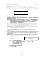
INSTALLATION REQUIREMENTS
Installation
1. INSTALLATION
!CAUTION
Before installing options, please do the following:
1. If there is a fax unit on the machine, print out all messages stored in the
memory, all user-programmed items, and a system parameter list.
2. If there is a printer option on the machine, print out all data in the
printer buffer.
3. Turn off the main switch and disconnect the power cord, the telephone
line, and the network cable.
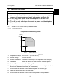
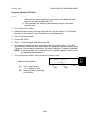
1.1 INSTALLATION REQUIREMENTS
1.1.1 ENVIRONMENT
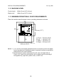
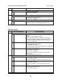
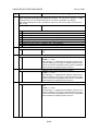
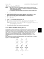
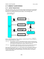
–Temperature and Humidity Chart–
Humidity
80%
54%
Operation range
15%
10°C
(50°F)
27°C
32°C
(80.6°F) (89.6°F)
Temperature
B046I512.WMF
1. Temperature Range: 10°C to 32°C (50°F to 89.6°F)
2. Humidity Range:
15% to 80% RH
3. Ambient Illumination: Less than 1,500 lux (Do not expose to direct sunlight.)
4. Ventilation:
Room air should turn over at least 3 times/hr/person
5. Ambient Dust
Less than 0.1 mg/m3
6. Do not install the machine where it will be exposed to direct sunlight or to direct
airflow (from a fan, air conditioner, air cleaner, etc.).
7. Do not install the machine where it will be exposed to corrosive gas.
8. Place the machine on a firm and level base.
9. Do not install the machine where it may be subjected to strong vibration.
1-1
INSTALLATION REQUIREMENTS
24 July, 2001
1.1.2 MACHINE LEVEL
Front to back:
Within 5 mm (0.2") of level
Right to left:
Within 5 mm (0.2") of level
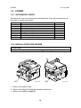
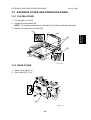
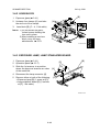
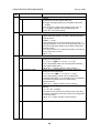
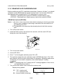
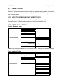
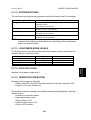
1.1.3 MINIMUM OPERATIONAL SPACE REQUIREMENTS
Place the machine near the power source, providing clearance as shown.
[C]
[D]
[B]
450 mm (17.7")
A: Front
B: Left
C: Rear
D: Right
[A]
468 mm (18.4")
>
>
>
>
750 mm (29.6")
100 mm (3.9")
105 mm (4.1")
230 mm (9.0")
B046I130.WMF
NOTE: 1) The 750-mm front space indicated above is sufficient to allow the paper
tray to be pulled out. Additional space is required to allow an operator to
stand at the front of the machine.
2) Actual minimum space requirement for left, rear, and right sides is
10mm (0.4") each, but note that this will not allow room for opening of
the bypass tray, right door, platen cover, or ADF unit.
1-2
24 July, 2001
INSTALLATION REQUIREMENTS
!CAUTION
1. Make sure that the wall outlet is near the machine and easily accessible.
After completing installation, make sure the plug fits firmly into the
outlet.
2. Avoid multi-wiring.
3. Be sure to ground the machine.
Input voltage:
North America:
Europe:
120 V, 60 Hz, 7 A
220 – 240 V, 50/60 Hz, 4 A
Image quality guaranteed at rated voltage ± 10%.
Operation guaranteed at rated voltage ± 15%.
1-3
Installation
1.1.4 POWER REQUIREMENTS
COPIER
24 July, 2001
1.2 COPIER
1.2.1 ACCESSORY CHECK
Check that you have the accessories indicated below. Note that accessories vary
according to model and location.
No.
1
2
3
4
5
6
7
8
Description
Copier Operating Instructions (-17, -26, -29)
EU safety sheet (-22, -24, -26, -27)
NECR (-17, -27, -29)
Paper-size decals
Energy Star seal (-26)
Branding plaques (-22)
Brand decals (-22)
Handset bracket (B046-17)
Q’ty
1
1
1
1 set
1
1 set
1 set
1
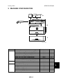
1.2.2 INSTALLATION PROCEDURE
!CAUTION
Make sure that the copier remains unplugged during installation.
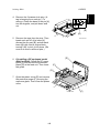
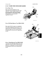
[A]
B046I101.WMF
[B]
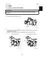
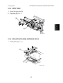
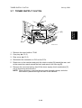
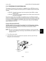
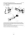
1. Remove the strips of tape.
2. Remove the bag [A] holding the included accessories.
3. Remove the spacing wedge [B].
1-4
B046I124.WMF
COPIER
Installation
24 July, 2001
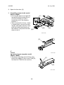
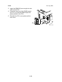
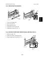
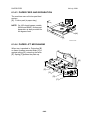
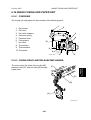
4. Remove the 3 scanner lock pins. (A
tag is hanging from each pin.) To
remove: Grasp the base of the pin [A],
turn 90 degrees, and pull down and
out.
[B]
[A]
5. Remove the tags from the pins. Then
break each pin off of its base [A],
discard the pin part [B], and set each
base [A] back into its original hole,
turning it 90° to lock it into place. (Be
sure to do this for all three pins.)
B046I106.WMF
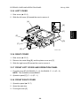
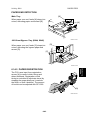
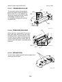
[E]
6. If installing a DF-equipped model
(B046 or B049): Raise the DF upper
guide [C] and remove the protective
paper [D] at the feed unit. Then lower
the guide.
[C]
[D]
7. Open the platen cover [E] and remove
the protective paper [F] covering the
exposure glass. Then close the platen
cover.
B046I107.WMF
1-5
[F]
COPIER
24 July, 2001
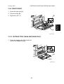
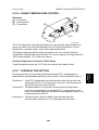
8. Open the front door [A].
9. If installing a toner-bottle model
(B044 or B046):
• Lift lever [B], press in on latch [C]
and pull the bottle holder [D] out.
(It is not necessary to pull it
completely out of the machine,
however.)
• Take a new bottle of toner, shake
it several times, remove its outer
cap [E], and load as shown. Then
push the bottle holder back into
the machine, and press the latch [B]
down to lock it.
[C]
[A]
[D]
B046I112.WMF
[E]
If
installi
ng a toner-hopper magazine model
(B045 or B049):
• Shake the magazine several times, then
peel off the paper [F] from a new THM [G],
and load the THM into the machine.
B046I301.WMF
[F]
[G]
B046I114.WMF
1-6
24 July, 2001
COPIER
Installation
[B]
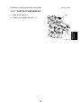
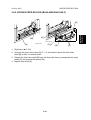
10. Remove the foam cushion [A] and pull the
tabbed strips [B] all the way out of the
PCU. Then close the front door.
[A]
B046I104.WMF
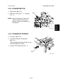
11. Pull open the paper tray, and remove the
tape [C] securing the end fence in the
compartment.
12. Push the bottom plate [D] down, load
paper, and adjust the side fences. If
loading paper shorter than A4, remove
the end fence [E] from its compartment,
set it into the tray, and adjust it to the
correct length.
[E]
[D]
[C]
B046I119.WMF
13. Push the tray back in.
14. Adhere the appropriate branding decal
(not shown) to the center of the front
door [F], and adhere the tray number
decal and appropriate paper-size decal
to the front of the paper tray (at [G]) as
shown.
15. Hong Kong only:
If installing model B046 or B049 in
Hong Kong, you must change the
position of the TB1 jumper on the NCU.
Turn to the fax service manual and carry
out steps 4 to 8 of the installation
procedure (fax service manual, section 1.2.2).
[F]
[G]
B046I515.WMF
16. Plug in the machine and turn on the main switch.
17. Enter SP mode, and run SP7-825 to initialize the electrical total counter to 0.
NOTE: 1) After selecting SP7-825, enter "1" and then hold down the Original
Type key and press the OK key to initialize the counter. If
initialization is successful, the screen displays "Action completed."
2) SP7-825 is effective only once, at time of machine installation.
1-7
COPIER
24 July, 2001
18. Models B046 and B049 only: Access SP5-992 and select "2" to print out a full
SMC report. Confirm that the report shows a "YES" for SP7-801-3.
19. Models B046 and B049 only: Press the On Hook key on the fax operation
panel, and confirm that you hear a dial tone coming from the monitor speaker.
20. Program the required items, as indicated below.
Initial Programming: Faxless models (B044, B045)
Items to Program (Service Level – SP Mode)*1
Date and time
Language replacement (Firmware download)
SP No.
5-302
5-827
*1: See Section 5 for SP-mode usage instructions.
Items to Program (User Level) *2
Display contrast
Energy saver level (low power mode)
Reception mode
Other items, as necessary
User Tools
User Tools →
System Settings
*2
*2: Refer to the Operating Instructions for details.
Initial Programming: Fax-equipped models (B046, B049)
Items to Program (Service Level – Service Functions)*3
Country code (System switch 0F)
Protocol requirements (G3 switch 0B) - EU only
PM call (System switch 01 – bit 0)
Country code (NCU parameter 00)
Service station's fax number
Function No.
01
01
01
07
09
*3: See Section 5.1.1 of the fax service manual for information about using
service functions.
1-8
COPIER
Items to Program (Service Level – SP Mode)*4
Machine's serial number
Language replacement (Firmware download)
PSTN access code (RAM address 4000DB)
PSTN access method (RAM address 4000CD)
Periodic service call (RAM addresses 40054F to 400553)
SP No.
5-811
5-827
7-955
*4: See Section 5 for SP-mode usage instructions.
Items to Program (User Administrator Level)*5
Monitor volume
Display contrast
Date and Time
Reception mode
Fax Header/Own Name/Own No. (TTI/RTI/CSI)
Reports on/off
Country Code (except NA)
Fusing power control during energy saver mode
Language selection
Other initial programming items
*5: Refer to the Operating Instructions for details.
1-9
User Tools
Fax Features
→ Setup
Key Op. Tools
System
Settings
Language
*5
Installation
24 July, 2001
PAPER TRAY UNIT
24 July, 2001
1.3 PAPER TRAY UNIT
1.3.1 ACCESSORY CHECK
Confirm that you have the accessories indicated below.
No.
1
2
3
Description
Paper-size decals
Installation Procedure (for service person)
Installation Procedure (for user)
Q’ty
1 sheet
1
1
1.3.2 INSTALLATION PROCEDURE
!CAUTION
Unplug the main machine's power cord before starting the following
procedure.
1. Remove the tape at [A], and the tape and cardboard at [B].
2. Pull the paper tray part way out of the unit, remove the tape and cardboard at
[C], and push the tray back in.
[B]
[C]
[A]
1-10
B046I516.WMF
24 July, 2001
PAPER TRAY UNIT
Installation
3. Set the machine onto the paper tray unit.
B046I527.WMF
4. Remove the paper tray from the paper tray unit.
5. Load paper into the paper tray. Adjust the side and end fences as necessary. If
loading 81/2"x 14" paper, remove the end fence and set it into the special
compartment.
6. Set the paper tray back into the paper tray unit.
7. Stick on the appropriate tray-number
decal and paper-size decal, at the
locations indicated in the illustration.
B046I517.WMF
1-11
PAPER TRAY UNIT HEATER
24 July, 2001
1.4 PAPER TRAY UNIT HEATER
1.4.1 ACCESSORY CHECK
Confirm that you have the accessories indicated below.
No.
1
2
3
4
5
6
7
8
9
10
Description
Grounding wire
Relay harness
Clamps
Ferrite core
Heater fastening screws
PTU fastening screws
Grounding screw
Decal for copier
Decal for paper unit
Tie wrap
Q’ty
1
1
2
1
2
3
1
1
1
1
1
2
3
10
4
9
5
8
6
7
B046I518.WMF
1.4.2 INSTALLATION PROCEDURE
!CAUTION
Unplug the main machine's power cord before starting the following
procedure.
1. If the paper tray unit is already installed, uninstall it by lifting the copier off of it.
(Refer to illustrations for Procedure 1.3.2, above.)
2. Remove both paper trays—the one from the copier, and the one from the
paper tray unit.
1-12
PAPER TRAY UNIT HEATER
3. Remove the ground screw [A] at the rear of the paper tray unit.
[C]
4. Fasten the heater [B] and the supplied
ground wire [C] to the paper tray unit
with 3 screws as shown. Note that [A]
is the grounding screw you removed at
Step 3 (returned to its original hole),
and [D] and [E] are the two supplied
heater fastening screws.
NOTE: Be sure to position the ground
wire [C] and heater harness [F]
so that they will be out of the
way of the copier when you set
it onto the paper tray unit.
[A]
[D]
Installation
24 July, 2001
[F]
[B]
[E]
5. Set the copier onto the paper tray unit.
B046I519.WMF
6. Screw the paper tray unit into place using
three supplied PTU fastening screws.
B046I500.WMF
1-13
PAPER TRAY UNIT HEATER
24 July, 2001
[B]
7. Open the front door [A] and remove the
copy tray [B] (!×1). Then close the
front door.
[A]
B046I501.WMF
8. Remove the rear cover [C] (! x 5).
[C]
B046I502.WMF
9. Remove the FCU cover plate [D] (7 screws on faxless machines, 8 screws on
fax-equipped machines).
NOTE: On fax-equipped machines, detach the NCU connector [E] first.
Faxless machines:
Fax-equipped machines:
[E]
[D]
B046I503.WMF
B046I504.WMF
1-14
24 July, 2001
PAPER TRAY UNIT HEATER
11. Pass relay harness [B] through the
circular opening at [C] (at the rear of
the PSU board bracket), and then
through the hole at [A]. Then connect
the relay harness to the heater's
harness [D].
Installation
10. Pass the heater's harness through the
hole [A] at the rear of the copier.
[A]
[B]
[C]
B046I520.WMF
[D]
[L]
[F]
12. Pull the relay harness back into the
copier. Then set the ferrite core [E]
over the relay harness, and push it
back so that it is over the heater's
harness.
[G]
[H]
13. Wrap the heater's harness once
around the core (see [F]). Adjust so
that the core is located toward the
rear of the copier (at position [E],
behind the rear clamp). Secure the
core into position using the supplied
tie wrap [G].
[J]
[E]
[K]
[I]
B046I521.WMF
14. Clip off the excess length of the tie
wrap [H].
15. Connect the relay harness connector [I] to the large connector at the front
center of the PSU board. Screw the ground wire [J] to the PSU board bracket,
using the included grounding screw.
16. Attach the supplied clamps [K] to corresponding holes on the PSU board
bracket, and set the heater harness though the clamps. Position the harness
so that the front clamp is between the two bindings [L] on the harness. Then
fasten the clamps.
1-15
PAPER TRAY UNIT HEATER
24 July, 2001
17. Pull the excess length of the heater's
harness out the hole at the rear [A].
NOTE: Be sure that the harness passes to
the side of the grounding plate [B]
at the bottom of the hole. (The front
of the grounding plate must remain
clear.)
[B]
[A]
B046I522.WMF
18. Arrange the excess harness length so that it sits beneath the
FCU cover plate.
19. Attach the caution decals
to the locations shown in
the illustration.
B046I523.WMF
20. Reinsert the paper trays, and reattach the copy tray and the rear cover.
1-16
DOCUMENT FEEDER
1.5 DOCUMENT FEEDER
1.5.1 ACCESSORY CHECK
Confirm that you have the components and accessories indicated below.
No.
1
2
3
4
5
6
7
8
–
Description
DF connection board
DF body
Hex wrench
Hex screws
DF original table
Wire harness
Phillips-head screws
Bracket
Installation Procedure
8
Q’ty
1
1
1
4
1
1
5
1
1
1
2
3
7
4
5
6
B046I524.WMF
1.5.2 INSTALLATION PROCEDURE
!CAUTION
Unplug the main machine's power cord before starting the following
procedure.
1-17
Installation
24 July, 2001
DOCUMENT FEEDER
24 July, 2001
1. Unpack the ADF and remove the packing
tape from the bottom of the ADF body.
[C]
2. Remove the platen cover [A]. To
remove: Lift the cover, unlatch the
two latches [B] (press down on
the tabs [C] and push the latch
back), and detach the cover from
the hook [D].
[A]
[B]
[D]
B046I505.WMF
3. Remove the left piece [E] of the copier's
platen cover by pushing the piece to the
left and then pulling it up and off.
[E]
B046I525.WMF
4. Place the DF original table [F] flat onto
the platen cover, so that the 3 latches
go all the way into the openings and so
that the contact area [G] around each
[1]
latch is flush against the cover. Then
push so that latch [1] locks into place,
then latch [2], and then latch [3] (at the
rear left).
NOTE: The latches may break if you
try to push the table in at an
angle.
[F]
[3]
[2]
[G]
B046I526.WMF
1-18
24 July, 2001
DOCUMENT FEEDER
Installation
5. Remove the rear cover [A] (! x 5).
[A]
B046I514.WMF
6. Remove the left scale plate [B] (! x 2).
[B]
B046I506.WMF
7. Set the DF body [C] onto the copier
in its correct position. Press the latch
[D] to raise the top half of the body,
and fasten to the copier with the 4
hex screws (using the included hex
wrench).
[D]
B046I528.WMF
[C]
1-19
DOCUMENT FEEDER
24 July, 2001
8. Install the DF connection board [A] and DF board bracket [B]. (! x 5)
[D]
[C]
[A]
[B]
B046I513.WMF
9. Connect the four wire sets from the DF body to CN103, CN105, CN106, and
CN107 on the DF connection board. (Not shown in illustration.)
10. Connect one end of the supplied wire harness [C] to CN101 and CN102 on the
DF connection board, and connect the other end to connectors CN9 and CN10
on the FCU. Secure the wire harness into the clamp [D] located to the side of
the DF board.
11. Reattach the rear cover and the platen cover.
12. Plug in the power cord, and turn on the main switch.
13. Make a full-size copy from the first tray using the ADF, and check the side-toside and leading edge registrations. If the registration is incorrect, adjust as
necessary (☛ 3.13.3).
1-20
24 July, 2001
DIMM
Installation
1.6 DIMM
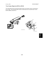
1.6.1 INSTALLATION PROCEDURE
!CAUTION
Unplug the main machine's power cord before starting the following
procedure.
1. Remove the rear cover [A] (! x 5).
[A]
B046I508.WMF
2. Remove the FCU cover plate [B] (7 screws on faxless machines, 8 screws on
fax-equipped machines).
NOTE: On fax-equipped machines, detach the NCU connector [C] first.
Faxless machines:
Fax-equipped machines:
[C]
[B]
B046I509.WMF
B046I510.WMF
1-21
DIMM
24 July, 2001
3. Insert the DIMM [A] at an angle into slot
CN2 on the FCU.
4. Press the free end of the DIMM toward
the FCU, so that the DIMM snaps into
place parallel to the FCU.
5. Reinstall the FCU cover plate and the
rear cover.
[A]
B046I105.WMF
1-22
24 July, 2001
PM TABLES
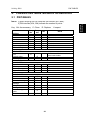
2. PREVENTIVE MAINTENANCE SCHEDULES
NOTE: 1) After carrying out PM, clear the PM counter (SP7-804).
2) PM intervals (45k, 90k) indicate the number of prints.
Key: AN: As necessary
C: Clean
Every
45k
OPTICS
Reflector
1st mirror
2nd mirror
3rd mirror
Platen cover
Exposure glass
Toner shield glass
Every
90k
C
C
C
C
C
C
C
R: Replace
I: Inspect
AN
C
C
C
C
C
C
C
NOTE
Optics cloth
Optics cloth
Optics cloth
Optics cloth
Dry cloth
Dry cloth
Dry cloth
DRUM AREA
PCU
Transfer roller
Discharge plate
PAPER FEED
Paper feed roller
Friction pad
Bottom-plate pad
Registration roller
FUSING UNIT
Hot roller
Pressure roller
Hot roller bearings
Pressure-roller
bushings
Inlet guide
Outlet guide
Hot roller stripper
pawls
Thermistor
On B044 and B046: Also clean
toner-bottle holder.
R
R
R
R
R
C
C
C
C
C
C
R
R
R
I
C
C
R
C
2-1
Water or alcohol.
Dry cloth
Water or alcohol.
Water or alcohol.
Preventive
Maintenance
2.1 PM TABLES
HOW TO CLEAR THE PM COUNTER
Every
90k
DF
Separation roller
Pick-up roller
White plate
DF exposure glass
Rollers R0, R1, R2
R
R
Every
120k
PAPER TRAY UNIT
Paper feed roller
Bottom-plate pad
Friction pad
24 July, 2001
AN
C
C
C
C
C
NOTE
Water or alcohol
Water or alcohol
Water or alcohol
Water
Water or alcohol
AN
NOTE
R
C
Dry cloth
R
2.2 HOW TO CLEAR THE PM COUNTER
After finishing PM, clear the PM counter as follows.
1. Access SP mode 7-804.
2. Hold down the Original Type key and press the OK key (or ! key) to reset the
counter. If the reset is successful, the display shows “Action completed.” If the
reset fails, the display shows “Error!!!”
2-2
24 July, 2001
PRECAUTIONS
3. REPLACEMENT AND ADJUSTMENT
3.1 PRECAUTIONS
3.1.1 GENERAL
!CAUTION
But note that you should not turn off the main switch while mechanical parts are
active, as this may cause parts to stop out of home position. Attempting to remove
or install the PCU or other such units while parts are out of home position may
result in damage. Wait for operation to stop before turning off the machine.
3.1.2 LITHIUM BATTERIES
!CAUTION: Lithium Batteries
Incorrect replacement of lithium battery(s) on the FCU poses risk of
explosion. Replace only with the same type or with an equivalent type
recommended by the manufacturer. Discard used batteries in accordance
with the manufacturer’s instructions.
3.1.3 PCU (PHOTOCONDUCTOR UNIT)
The PCU consists of the OPC drum, charge roller, development unit, and cleaning
components. Observe the following precautions when handling the PCU.
1. Never touch the drum surface with bare hands. If the drum surface is dirty or if
you have accidentally touched it, wipe it with a dry cloth, or clean it with wet
cotton and then wipe it dry with a cloth.
2. Never use alcohol to clean the drum. Alcohol will dissolve the drum surface.
3. Store the PCU in a cool dry place.
4. Do not expose the drum to corrosive gases (ammonia, etc.).
5. Do not shake a used PCU, as this may cause toner and developer to spill out.
6. Dispose of used PCU components in accordance with local regulations.
3.1.4 TRANSFER ROLLER
1. Never touch the surface of the transfer roller with bare hands.
2. Be careful not to scratch the transfer roller, as the surface is easily damaged.
3-1
Replacement
Adjustment
Turn off the main power switch and unplug the machine before starting any
of the replacement procedures described in this section.
PRECAUTIONS
24 July, 2001
3.1.5 SCANNER UNIT
3.1.6 LASER UNIT
1. Do not loosen or adjust the screws securing the LD drive board on the LD unit.
Doing so will throw the LD unit out of adjustment.
2. Do not adjust the variable resistors on the LD unit, as these are permanently
adjusted at the factory. If replacement of the LD drive board is necessary,
replace the entire LD unit.
3. Keep the polygon mirror and toroidal lens free of dust. Laser performance is
very sensitive to dust on these components.
4. Do not touch the shield glass, the lenses, or the surface of the polygon mirror
with bare hands.
3.1.7 FUSING UNIT
1. After installing the fusing thermistor, make sure that it is in contact with the hot
roller and that the roller can rotate freely.
2. Be careful to avoid damage to the hot roller stripper pawls and their tension
springs.
3. Do not touch the fusing lamp and rollers with bare hands.
4. Make sure that the fusing lamp is positioned correctly and that it does not touch
the inner surface of the hot roller.
3.1.8 PAPER FEED
1. Do not touch the surface of paper feed rollers.
2. To avoid misfeeds, the side and end fences in each paper tray must be
positioned correctly so as to align with loaded paper size.
3-2
Replacement
Adjustment
1. Use alcohol or glass cleaner to clean the exposure and scanning glass. This
will reduce the static charge on the glass.
2. Use a blower brush or a water-moistened cotton pad to clean the mirrors and
lenses.
3. Take care not to bend or crease the exposure lamp’s ribbon cable.
4. Do not disassemble the lens unit. Doing so will throw the lens and copy image
out of focus.
5. Do not turn any of the CCD positioning screws. Doing so will throw the CCD out
of position.
24 July, 2001
SPECIAL TOOLS AND LUBRICANTS
3.1.9 IMPORTANT
3.2 SPECIAL TOOLS AND LUBRICANTS
Part Number
A1849501
A2929500
A0299387
N8036701
N8031000
A2579300
52039501
G0219350
Description
Optics Adjustment Tools (2 pcs/set)
Test Chart – S5S (10 pcs/set)
Digital Multimeter – Fluke 87
Flash Memory Card (4MB)
Case for Flash Memory Card
Grease Barrierta – S552R
Silicone Grease G-501
Loopback connector
3-3
Q’ty
1 set
1 set
1
1
1
1
1
1
Common with...
Skylark
Mojito
Russian-C, Stinger-C
Russian-C, Stinger-C
Russian-C, Stinger-C
Russian-C, Stinger-C
Russian-C, Stinger-C
Russian-C, Stinger-C
Replacement
Adjustment
1. The machine will automatically start toner agitation when you install a new
PCU. Be sure to wait for initialization to finish before reopening the front cover
or turning off the main switch.
2. If the optional anti-condensation heater (for the optional paper tray unit) is
installed, keep the copier's power cord plugged in even while the main switch is
off, so that the heater remains energized.
EXTERIOR COVER AND OPERATION PANEL
24 July, 2001
3.3 EXTERIOR COVER AND OPERATION PANEL
3.3.1 PLATEN COVER
1. Lift the platen cover [A].
2. Unlatch the two latches [B].
NOTE: To unlatch, press down on the tabs [C] and then push the latch back.
3. Detach the cover from the hook [D]
[C]
[B]
[D]
B046R904.WMF
3.3.2 REAR COVER
1. Platen cover (☛ 3.3.1)
2. Rear cover [A] (! x 5)
[A]
B046R903.WMF
3-4
Replacement
Adjustment
[A]
24 July, 2001
EXTERIOR COVER AND OPERATION PANEL
3.3.3 COPY TRAY
1. Open the front door [A].
2. Copy tray [B] (! x 1)
Replacement
Adjustment
[B]
[A]
B046R912.WMF
3.3.4 SCALE PLATE (B044 AND B045 ONLY)
1. Scale plate [A] (! × 2)
[A]
B046R551.WMF
3-5
EXTERIOR COVER AND OPERATION PANEL
24 July, 2001
3.3.5 LEFT COVER
1. Rear cover (☛ 3.3.2)
2. Slide the left cover [A] toward the rear to remove it.
[A]
[C]
[E]
[D]
[F]
[G]
B046R901.WMF
3.3.6 RIGHT COVER
1. Rear cover (☛ 3.3.2)
2. Remove the metal fitting [B], and the platen-cover arm [C].
3. Slide the right cover [D] toward the rear to remove it.
3.3.7 FRONT LEFT COVER AND OPERATION PANEL
1. Front left cover [E] (On B044/5: ! × 2) (On B046/9: ! × 2, " × 2)
NOTE: The illustration shows B046/9.
2. Operation panel [F] (! × 4, " × 1)
3.3.8 FRONT RIGHT COVER
1. Operation panel (☛ 3.3.7)
2. Open the right door.
3. Front right cover [G]
3-6
Replacement
Adjustment
[B]
24 July, 2001
EXTERIOR COVER AND OPERATION PANEL
3.3.9 RIGHT DOOR
1. Open the right door [A].
2. Undo the strap [B].
3. Right door (" × 1)
[A]
B046R909.WMF
3.3.10 BYPASS TRAY (B044 AND B046 ONLY)
1. Press the stopper rails [A] inward and
remove the bypass tray [B].
[B]
[A]
B046R908.WMF
3-7
Replacement
Adjustment
[B]
EXTERIOR COVER AND OPERATION PANEL
24 July, 2001
3.3.11 PLATEN COVER SENSOR
1. Rear cover (☛ 3.3.2)
[A]
B046R931.WMF
3-8
Replacement
Adjustment
2. Platen cover sensor [A] (" × 1)
24 July, 2001
SCANNER SECTION
3.4 SCANNER SECTION
3.4.1 EXPOSURE GLASS
[A]
Replacement
Adjustment
[B]
B046R005.WMF
Non-DF machines
1. Rear cover (☛ 3.3.2)
2. Scale plate (☛ 3.3.4)
3. Exposure glass [A]
DF-equipped machines
1. Rear cover (☛ 3.3.2)
2. Right cover (☛ 3.3.6)
3. Exposure glass [A]
NOTE: When reinstalling: Be sure that the marking on the glass is at the rear left
corner, and be sure the left edge of the glass is aligned flush against the
support ridge [B] on the frame.
3-9
SCANNER SECTION
24 July, 2001
3.4.2 LENS BLOCK
[B]
1. Exposure glass (☛ 3.4.1)
[A]
2. Unclamp four clamps [A], and take
the wire out of the clamps.
Lens block [B] (! × 4, 1 flat cable)
NOTE: 1) Do not loosen the paintlocked screws holding the
lens unit in place.
2) After installing a new lens
block, carry out copy
adjustments. (☛ 3.13)
B046R003.WMF
3.4.3 EXPOSURE LAMP, LAMP STABILIZER BOARD
1. Exposure glass (☛ 3.4.1)
[E]
[B]
2. Operation panel (☛ 3.3.7)
3. Slide the 1st scanner to a position
where the lamp and scanner are clear
of the metal lids.
[A]
[D]
4. Disconnect the lamp connector [A].
5. Remove either or both of the following:
• Exposure lamp [B] (1 screw at [C])
• Lamp stabilizer board [D] (2 screws
at [E], 1 flat cable)
[C]
B046R001.WMF
3-10
Replacement
Adjustment
3.
24 July, 2001
SCANNER SECTION
3.4.4 SCANNER MOTOR
1. Right cover (☛ 3.3.6)
[A]
2. Scanner motor [A] (! × 4, 1 spring,
" × 1)
B046R923.WMF
3.4.5 SCANNER HP SENSOR
1. Left cover (☛ 3.3.6)
2. If non-DF machine: Scale plate
(☛ 3.3.4)
If DF-equipped machine: Press on the
DF latch and open the DF.
3. Scanner HP sensor [A] (" × 1)
[A]
B046R020.WMF
3-11
Replacement
Adjustment
NOTE: When reinstalling: Fasten the
screws loosely, then set the
spring in place, then tighten up
the screws.
SCANNER SECTION
24 July, 2001
3.4.6 SCANNER ALIGNMENT ADJUSTMENT
1. Remove the rear cover (☛ 3.3.2), operation panel (☛ 3.3.7), and exposure
glass (☛ 3.4.1).
Replacement
Adjustment
2. Loosen the 2 screws holding the 1st and
2nd scanner belts in place.
B046D002.WMF
3. Slide the 1st and 2nd scanners so that all four of the following are roughly
aligned on both the front and back sides:
• The hole on the copier's lid
• The hole on the 1st scanner
• The corner right hole on the 2nd scanner
• The hole at the base of the scanner
[A]
4. Insert the two optics adjustment tools
[A], and adjust the scanners as
necessary so that the tools go through
all four holes.
5. Tighten the two screws that you
loosened at step 2 above, so that the
belts are firmly clamped into place.
6. Remove the adjustment tools.
B046D003.WMF
3-12
24 July, 2001
FUSING
3.5 FUSING
3.5.1 FUSING UNIT
!CAUTION
The fusing unit can become very hot. Be sure that it has cooled down
sufficiently before handling it.
1. Turn off the main switch, and unplug the machine.
3. Fusing unit [A] (! × 3, " × 3)
NOTE: When reinstalling the unit:
Replace the spacer [B] in the
correct position, and
remember to set the
grounding wire [C] into place.
Replacement
Adjustment
2. Copy tray (☛ 3.3.3)
[C]
[B]
[A]
B046R501.WMF
3.5.2 EXIT SENSOR
1. Fusing unit (☛ 3.5.1)
2. Exit sensor [A] (" × 1)
[A]
B046R508.WMF
3-13
FUSING
24 July, 2001
3.5.3 HOT ROLLER STRIPPER PAWLS
[A]
Replacement
Adjustment
[B]
B046R502.WMF
[E]
[D]
B046R507.WMF
[C]
1. Fusing unit (☛ 3.5.1)
2. Separate the fusing unit into two sections: the hot roller section [A], and the
pressure roller section [B]. (! × 2)
NOTE: After removing the screws, lower the pressure roller section about
halfway and then slide it toward the front side to detach it.
3. Hot roller stripper pawls [C] (1 spring for each pawl)
NOTE: 1) To remove the right pawl, first remove the plastic spacer at [D]
(! × 1).
2) When reinstalling the center pawl, be sure to set roller [E] back
into place.
3-14
24 July, 2001
FUSING
3.5.4 HOT ROLLER & FUSING LAMP
[A]
1. Hot roller stripper pawls (☛ 3.5.3)
2. Hot roller assembly [A] (! × 2)
NOTE: 1) Each of the screws has a
washer.
2) After removing the screws,
lift the hot roller assembly
out from the rear side.
B046R505.WMF
[B]
4. Hot roller [C] (2 C-rings, 1 spacer,
1 gear, 2 bushings)
[B]
[C]
B046R509.WMF
3.5.5 THERMOFUSE, THERMOSWITCH, AND THERMISTOR
1. Remove the hot roller assembly
from the hot roller section.
(☛ 3.5.3)
2. Thermofuse [A] (! × 2).
[C]
3. Thermoswitch [B] (! × 2)
NOTE: You must remove the
thermofuse first.
[A]
[B]
4. Thermistor [C] (! × 1)
B046R506.WMF
3-15
Replacement
Adjustment
3. Fusing lamp [B]
FUSING
24 July, 2001
3.5.6 PRESSURE ROLLER
1. Fusing unit (☛ 3.5.1)
2. Separate the fusing unit into two
sections: the hot roller section and the
pressure roller section (☛ 3.5.3, Step 2).
Carry out the remaining steps on the
pressure roller section.
[A]
B046R504.WMF
[C]
4. 2 springs ([B], [C])
[H]
5. 2 pressure arms ([D], [E])
NOTE: Manipulate each arm so
that it comes out through
the slit in the casing.
[E]
[B]
[D]
6. 2 bushings ([F], [G])
[G]
7. Pressure roller [H]
[F]
B046R503.WMF
3-16
Replacement
Adjustment
3. Fusing entrance guide [A]
24 July, 2001
PCU
Replacement
Adjustment
3.6 PCU
[A]
[B]
B046I109.WMF
1. Open the right door.
NOTE: Do not forget to open the right door. The PCU may become stuck if
you try to remove it while the front door is closed.
2. Open the front door.
3. Remove the toner bottle holder or THM.
NOTE: If working on a toner-bottle model, clean away all spilled toner from the
toner bottle area and from the inside of the front door.
4. Detach the connector [A] and pull out the PCU [B].
NOTE: 1) After installing the new PCU, be sure to remove the Styrofoam piece
and to pull off the two tags. (☛ 1.1.2, Step 10)
2) The machine will automatically detect the new PCU and begin toner
initialization. (☛ 6.10.4)
3-17
TONER SUPPLY CLUTCH
24 July, 2001
3.7 TONER SUPPLY CLUTCH
[A]
[B]
B046R932.WMF
1. Remove the toner bottle or THM.
2. Copy tray (☛ 3.3.3)
3. Rear cover (☛ 3.3.2)
4. Disconnect the connector on C19 on the FCU.
5. Reach into to the machine and push the clutch coupler [A] toward the rear, and
at the same time reach around the back and remove the clip ring [B].
6. Remove the cone and spring, then lift the toner supply clutch mechanism [C]
out of its housing and remove it.
NOTE: When removing, note how the wire goes through a clamp, and also
note where it passes through the rear of the machine.
3-18
Replacement
Adjustment
[C]
24 July, 2001
PAPER FEED SECTION
3.8 PAPER FEED SECTION
3.8.1 PAPER FEED ROLLER AND FRICTION PAD
[B]
1. Take out the paper tray.
2. Clip ring [A]
4. Remove either or both of the following:
• Paper feed roller [B]
• Friction pad [C]
[C]
[A]
B046R702.WMF
3.8.2 PAPER END SENSOR
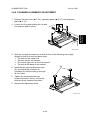
1. Take out the paper tray.
2. Open the right door.
3. PCU (☛ 3.5)
4. Paper end sensor [A] (" × 1)
NOTE: When installing the new sensor,
reach your left hand in through the
front and your right hand in
through the right side, and view
from the right side.
B046R929.WMF
[A]
3-19
Replacement
Adjustment
3. Pull the shaft back, and lift it out.
PAPER FEED SECTION
24 July, 2001
3.8.3 REGISTRATION SENSOR
Replacement
Adjustment
[C]
[A]
[B]
B046R926.WMF
B046R927.WMF
1. Take out the paper tray.
2. Open the right door.
3. Black guide piece [A]
4. Registration sensor feeler [B]
5. Registration sensor [C] (" × 1)
3.8.4 BYPASS PAPER END SENSOR (B044 AND B046 ONLY)
1. Right door (☛ 3.3.9)
2. Detach the sensor compartment [A].
3. Bypass paper end sensor [B] (" × 1)
[A]
B046R924.WMF
[B]
3-20
24 July, 2001
PAPER FEED SECTION
3.8.5 BYPASS FEED ROLLER (B044 AND B046 ONLY)
[B]
Replacement
Adjustment
[B]
[A]
B046R938.WMF
[A]
B046R930.WMF
[D]
[E]
[C]
1. Right door (☛ 3.3.9)
2. Unscrew the feed roller frame [A] (! × 2) and rotate it about the feed roller
shaft [B] so that it is upside down.
3. Detach the feed roller shaft [B] from the feed roller frame (unsnap the two snap
pawls [C] and remove the spacer [D]).
4. Bypass feed roller [E]
3-21
PAPER FEED SECTION
24 July, 2001
3.8.6 BYPASS FEED CLUTCH (B044 AND B046 ONLY)
1. Rear cover (☛ 3.3.2)
2. Right door (☛ 3.3.9)
4. Unscrew the bypass feed roller
housing [B] (! × 2), and pull it out of
the machine.
NOTE: It is not necessary to remove
or disconnect the bypass
paper end sensor.
5. Bypass feed clutch [C] (# × 1)
B046R925.WMF
[B]
[C]
3.8.7 BYPASS FRICTION PAD (B044 AND B046 ONLY)
1. Right door (☛ 3.3.9)
2. Detach the roller housing [B] (! × 2),
and move it out of the way.
3. Bypass friction pad [A]
[A]
B046R937.WMF
3.8.8 REGISTRATION CLUTCH
[C]
1. Rear cover (☛ 3.3.2)
2. High-voltage power supply board
(☛ 3.12.2)
3. Ground plate [A] (!)
4. Registration clutch [B] ($× 1, " × 1)
NOTE: To free the clutch, pry clip
[C] gently away from it using
a screwdriver.
[A]
3-22
[B]
B046R950.WMF
Replacement
Adjustment
[A]
3. Detach the bypass feed clutch
connector [A] from CN3 on the
high-voltage power supply board.
24 July, 2001
PAPER FEED SECTION
3.8.9 PAPER FEED CLUTCH
[B]
[C]
Replacement
Adjustment
[A]
B046R920.WMF
[D]
[E]
B046R922.WMF
1. Pull the paper tray part way out.
2. High-voltage power supply board
(☛ 3.12.2)
3. Main motor (☛ 3.12.4)
4. Remove 1 screw [A] from the small cover plate.
5. Open 3 clamps [B] on the large cover plate, and remove the wiring.
6. Detach two connectors [C] from the FCU.
7. Large cover plate [D] (! × 7, # × 2, 2 bushings)
8. Paper feed clutch [E]
3-23
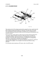
IMAGE TRANSFER
3.9
24 July, 2001
IMAGE TRANSFER
3.9.1 IMAGE TRANSFER ROLLER
[B]
1. Right door (☛ 3.3.9)
2. Raise the levers ([A], [B]) at the ends
of the image transfer roller, and
remove the roller [C].
[C]
[A]
Replacement
Adjustment
NOTE: 1) Note the position of the
2 springs [D] at each end.
When reinstalling the roller,
be sure that the pegs on the
plastic end pieces fit into the
springs.
2) Do not touch the transfer
roller surface with bare
hands.
B046R915.WMF
[D]
3.9.2 ID (IMAGE DENSITY) SENSOR
[B]
[A]
B046R913.WMF
B046R914.WMF
1. Right door (☛ 3.3.9)
2. Push in the latches as shown, and pry off
the entire section [A].
3. ID sensor [B] (" × 1)
3-24
24 July, 2001
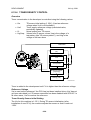
FUNCTION CONTROL UNIT (FCU)
3.9.3 DISCHARGE PLATE
1. Right door (☛ 3.3.9)
[A]
B046R934.WMF
3.10 FUNCTION CONTROL UNIT (FCU)
NOTE: 1) Before starting replacement, use SP5-824 to save SRAM user data from
the existing FCU into a flash memory card. After finishing the
replacement, use SP5-825 to reload the data from the card into the
SRAM on the new FCU. For instructions, see Section 5.1.8.
2) Replacement FCUs ship with the battery jumper switch set to the OFF
position. Be sure to change the jumper switch to the ON position before
installing the replacement FCU.
3-25
Replacement
Adjustment
2. Use a tweezers to remove the
discharge plate [A].
FUNCTION CONTROL UNIT (FCU)
24 July, 2001
Faxless machine
Fax-equipped machine:
[A]
B046R907.WMF
B046R910.WMF
[D]
B046R911.WMF
[C]
1. Rear cover (☛ 3.3.2)
2. FCU cover plate [A] (7 screws on faxless machines, 8 on fax-equipped
machines)
NOTE: On fax-equipped machines, detach the NCU connector [B] first, then
unscrew the cover plate and remove the cover plate together with the
NCU.
3. FCU [C] (all connectors, 2 flat cables, ! x 6)
NOTE: If an optional DIMM is installed on the FCU, remove it and install it on
the new FCU. (☛ 1.6)
4. Before installing the new board, set the new board's TB1 battery jumper switch
[D] to the ON position.
3-26
Replacement
Adjustment
[B]
24 July, 2001
LASER UNIT
3.11 LASER UNIT
!WARNING
The laser beam can cause serious eye damage. Be sure that the main
power switch is off and that the machine is unplugged before accessing
the laser unit.
Replacement
Adjustment
3.11.1 LOCATION OF “CAUTION” DECAL
B046I103.WMF
B046RLW.WMF
3-27
LASER UNIT
24 July, 2001
3.11.2 PSU BRACKET
1. FCU (☛ 3.10)
NOTE: After removing the copy tray, leave the front door open.
Replacement
Adjustment
2. Remove the 4 screws at [A].
[A]
B046R905.WMF
3. Unscrew the 6 screws securing the
PSU bracket [B], and detach the 4
connectors.
NOTE: Use a stubby screwdriver to
remove the 2 screws at [C].
4. Hold the PSU bracket at the rear
(viewing from the front of the
machine), pull the rear end out to the
left slightly, then lift the bracket
upward at the rear so that it comes
free of the hooks [D] at the front.
5. Pull the PSU bracket out.
[C]
[B]
[D]
B046R906
3-28
24 July, 2001
LASER UNIT
3.11.3 LASER UNIT
[A]
[B]
[D]
[C]
B046I103.WMF
1. PSU bracket (☛ 3.11.2)
NOTE: After removing the PSU bracket, leave the front door open.
Replacement
Adjustment
B046R101.WMF
2. Release the toner bottle holder (if model B044 or B046) or THM (if model B045
or B049), and pull it out slightly. (Illustration shows toner-bottle model.)
3. Laser unit [A] (! x 3, " x 2)
NOTE: When reinstalling the laser unit, be sure that the wire at [B] passes
under the unit. In particular, be certain that the wire does not pass in
front of the glass area on the unit.
3.11.4 LD UNIT
1. Laser unit (☛ 3.11.3)
2. Remove the harness ([C] in figure above)
from the clamp [D].
[F]
[E]
3. Laser unit cover [E] (! x 2)
4. LD unit [F] (! x 2)
NOTE: The LD drive board itself is not
adjustable, and is not a replaceable
part. You must replace the entire
bracket.
3.11.5 POLYGON MIRROR MOTOR
[D]
[G]
B046R102.WMF
1. Laser unit (☛ 3.11.3)
2. Remove the harness ([C] in figure above)
from the clamp [D].
3. Laser unit cover [E] (! x 2)
4. Polygon mirror motor [G] (! x 4)
3-29
OTHER REPLACEMENTS
24 July, 2001
3.12 OTHER REPLACEMENTS
3.12.1 QUENCHING LAMP
1. PCU (☛ 3.1.3)
[A]
B046R928.WMF
3.12.2 HIGH-VOLTAGE POWER SUPPLY BOARD
1. Rear cover (☛ 3.3.2)
2. High-voltage power supply
board [A] (! × 4, all connectors)
[A]
B046R936.WMF
3.12.3 PSU
[A]
1. Copy tray
2. PSU [A] (! × 6, all connectors)
B046R935.WMF
3-30
Replacement
Adjustment
2. Quenching lamp [A] (" × 1)
24 July, 2001
OTHER REPLACEMENTS
3.12.4 MAIN MOTOR
1. Rear cover (☛ 3.3.2)
2. Main motor [A] (! × 4, " × 1)
B046R919.WMF
3.12.5 EXHAUST FAN
1. Rear cover (☛ 3.3.2)
2. Exhaust fan [A] (! × 2, " × 1)
[A]
B046R918.WMF
3-31
Replacement
Adjustment
[A]
COPY IMAGE ADJUSTMENTS: PRINTING/SCANNING
24 July, 2001
3.13 COPY IMAGE ADJUSTMENTS: PRINTING/SCANNING
3.13.1 PRINTING
NOTE: 1) Make sure the paper is installed correctly in each paper tray before you
start these adjustments.
2) Use the Trimming Area Pattern (SP5-902, No.10) to print the test
pattern for the printing adjustments below.
3) Reset SP5-902 to 0 after completing these printing adjustments.
Registration - Leading Edge/Side-to-Side
1. Check the leading edge registration [A] for each paper feed station, and adjust
each of these registrations using SP1-001.
Tray
Paper tray(s)
100-sheet bypass
1-sheet bypass
SP mode
SP1-001-1
SP1-001-2
Specification
0 ± 2 mm
0 ± 2 mm
0 ± 4 mm
B
A
2. Check the side-to-side registration [B] for each paper
feed station, and adjust these registrations using SP1002. (Adjust the trays in order: the 1st tray first, then
the 2nd tray [if installed], then the bypass).
Tray
SP mode
Specification
1st tray
2nd tray
100-sheet bypass
1-sheet bypass
SP1-002-1
SP1-002-2
0 ± 2 mm
SP1-002-5
0 ± 2 mm
0 ± 4 mm
3-32
B046R552.WMF
A: Leading Edge Registration
B: Side-to-side Registration
Replacement
Adjustment
NOTE: 1) You need to perform these adjustment after executing a Memory All
Clear, and after replacing or adjusting any of the following parts.
• First or second scanner
• Lens Block
• Scanner Motor
• Polygon Mirror Motor
• Paper Tray
2) For detailed explanations about how to access and use SP mode, see
Section 5.
24 July, 2001
COPY IMAGE ADJUSTMENTS: PRINTING/SCANNING
Blank Margin
NOTE: If the leading edge or side-to-side registration cannot be adjusted to within
the specification, then adjust the leading-edge blank margin or the left-side
blank margin.
1. Check the trailing edge and right side edge blank margins, and adjust them
using the following SP modes.
Specification
SP2-101-4
3 ± 2 mm
SP2-101-12
5 ± 3 mm
SP2-101-6
2 +2.5/-1.5 mm
SP2-101-1
3 ± 2 mm
SP2-101-11
5 ± 3 mm
SP2-101-5
2 ± 1.5 mm
D
C
A
B
B046R553.WMF
A: Trailing Edge Blank Margin
B: Right Edge Blank Margin
C: Leading Edge Blank Margin
D: Left Edge Blank Margin
Main-Scan Magnification
1. Print the single-dot grid pattern (SP5-902-5).
2. Check the magnification (the grid size should be 2.7 x 2.7 mm), and if
necessary use SP2-998 to adjust it. The specification is 100 ± 1% in both
directions.
3-33
Replacement
Adjustment
Trailing edge (except
for 1-sheet bypass)
Trailing edge for 1sheet bypass
Right edge
Leading edge (except
for 1-sheet bypass)
Leading edge for 1sheet bypass
Left edge
SP mode
COPY IMAGE ADJUSTMENTS: PRINTING/SCANNING
24 July, 2001
3.13.2 SCANNING
NOTE: 1) Before doing the following scanner adjustments, check and adjust the
printing leading-edge and side-to-side registrations and the printing
blank margins (as described above).
2) Use an A4 test chart to perform the following adjustments.
Registration: Platen Mode
1. Place the test chart on the exposure glass
and make a copy from one of the feed
stations.
Replacement
Adjustment
[A]
2. Check the leading edge registration [A],
and adjust as necessary using SP4-010.
(Specification is 0 ± 2mm.)
B046R557.WMF
Magnification
A
B
A: Main scan magnification
B: Sub-scan magnification
B046R555.WMF
Main Scan Magnification
1. Place the A4 test chart on the exposure glass and make a copy from one of the
feed stations.
2. Check the magnification ratio. If necessary, adjust the magnification using the
following SP mode.
Main Scan Magnification
SP mode
SP4-008
3-34
Specification
± 1.0%
24 July, 2001
COPY IMAGE ADJUSTMENTS: PRINTING/SCANNING
Sub-scan Magnification
1. Place the A4 test chart on the exposure glass and make a copy from one of the
feed stations.
2. Check the magnification ratio. If necessary, adjust the magnification using the
following SP mode.
Sub-scan magnification
SP mode
SP4-101
Specification
± 1.0%
This procedure adjusts the standard white density level. Carry out this adjustment
after doing any of the following:
• After replacing the standard white plate.
• After replacing the FCU.
• After replacing the lens block.
• After performing a memory all clear (SP5-801).
Procedure:
1. Place 10 sheets of new A4 paper on the exposure glass, and close the platen
cover.
2. Access SP4-908, enter "1", and press OK. The machine automatically adjusts
the standard white density.
3-35
Replacement
Adjustment
Standard White Density Adjustment
COPY IMAGE ADJUSTMENTS: PRINTING/SCANNING
24 July, 2001
3.13.3 DF IMAGE ADJUSTMENT
Registration and Blank Margin
A
A: Leading edge registration
B: Side-to-side registration
B046R556.WMF
B046R559.WMF
NOTE: Make a temporary test chart as shown above, using A4 / 81/2"x11" paper.
1. Place the temporary test chart on the DF and make a copy from one of the feed
stations.
2. Check the registrations, and adjust as necessary using SP mode, as follows.
SP mode
SP6-006-1
SP6-006-2
SP6-006-3
Side-to-side registration
Leading edge registration
Blank margin for the trailing edge
Sub-scan Magnification
A: Sub-scan magnification
A
B046R558.WMF
NOTE: Make a temporary test chart as shown above, using A4 / 81/2"x11" paper.
1. Place the temporary test chart on the DF and make a copy from one of the feed
stations.
2. Check the registration, and if necessary adjust it using SP6-007. The
specification is ±1.0%.
3-36
Replacement
Adjustment
B
24 July, 2001
SERVICE CALL CONDITIONS
4. TROUBLESHOOTING
4.1 SERVICE CALL CONDITIONS
4.1.1 SUMMARY
There are two service-call levels, as follows.
A
B
Definition
To prevent possible damage to the
machine, level-A service calls can be
cleared only by a service representative
The machine will not operate until the
representative clears the call.
These SCs can be cleared by turning
the main power switch off and on.
Reset Procedure
Enter SP 5-810 (SC code reset) and
select “1”. Then simultaneously press
the Original Type key and the OK (or
!) key. (There is no need to turn the
main switch off and on.).
Turn the main power switch off and on.
NOTE: 1) If a problem involves circuit boards: Before deciding to replace a circuit
board, first see if you can solve the problem by disconnecting and then
reconnecting all connectors.
2) If a problem involves a motor lock: Check the mechanical load first,
before deciding whether to replace motors or sensors.
3) If working on a fax-equipped machine, keep in mind that switching
power off and back on may in some cases cause loss of data stored in
SAF memory.
4-1
Troubleshooting
Level
SERVICE CALL CONDITIONS
24 July, 2001
4.1.2 SC CODE DESCRIPTIONS
No. Definition
SC
Error
Level
Code Code
101
1-04
B
120
121
122
123
9-93
9-92
9-91
9-90
B
B
B
B
Symptom
Possible Cause
Exposure Lamp Error
Insufficient white level detected
when scanning the white plate.
Scanner home position error 1
Scanner home position sensor
did not detect OFF condition
during initialization or copying.
Scanner home position error 2
Scanner home position sensor
did not detect ON condition
during initialization or copying.
Scanner home position error 3
Scanner home position sensor
did not detect OFF condition
during book or ADF scan
operation.
Scanner home position error 4
Scanner home position sensor
did not detect ON condition
during book or ADF scan
operation.
4-2
• Exposure lamp defective
• SBU harness defective
• Bad connection
• Defect in optics system (dirty
scanner mirror, mirror out of
position, etc.)
• Lamp stabilizer board (or
connector) defective
• Incorrect start position or length for
white plate scanning (☛ SP4-015)
• Scanner HP sensor out of position
• Forgot to remove one or more of
the scanner stoppers
• Scanner motor defective
• Scanner HP sensor (or connector)
defective
• FCU defective
• Scanner belt loose or detached
• Forgot to remove one or more of
the scanner stoppers
• Scanner motor defective
• Scanner HP sensor (or connector)
defective
• FCU defective
• Scanner belt loose or detached
• Forgot to remove one or more of
the scanner stoppers
• Scanner motor defective
• Scanner HP sensor (or connector)
defective
• FCU defective
• Scanner belt loose or detached
• Forgot to remove one or more of
the scanner stoppers
• Scanner motor defective
• Scanner HP sensor (or connector)
defective
• FCU defective
• Scanner belt loose or detached
24 July, 2001
SERVICE CALL CONDITIONS
302
320
322
390
391
392
9-17
9-23
9-20
9-73
9-29
9-74
B
B
B
B
B
B
Symptom
Possible Cause
SBU auto-adjustment error
During SBU auto-adjustment
(☛ SP4-908), the detected
white level was out of range.
Charge roller current leak
Current leak at the charge
roller was detected.
Polygon mirror motor error
Did not detect lock signal from
polygon mirror motor within 10
seconds after motor ON signal;
or, lost lock signal for
continuous 1.5 seconds after
signal was detected.
Laser synchronization error
Detected LD error signal for
continuous 1.5 seconds while
polygon mirror motor was
running at constant speed.
TD sensor error
The TD sensor output less
than 0.33 V or greater than
2.64 V ten times in succession.
Development bias leak
Development bias leak signal
was detected.
Developer initialization error
Error reading ID sensor pattern
during developer initialization.
4-3
• SBU auto adjustment was not done
correctly (☛ 3.13)
• Exposure lamp defective
• SBU harness defective
• Bad connection
• Defect in optics system (dirty
scanner mirror, mirror out of
position. etc.)
• Defective stabilizer board (or
connector)
• Incorrect start position or length for
white plate scanning (☛ SP4-015)
• Scanner HP sensor out of position
• Charge roller damaged
• High voltage supply board defective
• Poor connection of the PCU
• Polygon mirror motor (or harness)
defective
• FCU defective
• Synchronization detection mirror
defective
• LD unit defective
• FCU defective
• LD harness damaged
• THM not in place
• TD sensor defective
• Bad connection
• Development roller defective
• High voltage supply board defective
• Forgot to remove heat seal from
replacement PCU
• ID sensor defective
• TD sensor defective
• Drum is not turning
• Development roller is not turning
• Right door not closed firmly
Troubleshooting
No. Definition
SC
Error
Level
Code Code
192
1-05
B
SERVICE CALL CONDITIONS
No. Definition
SC
Error
Level
Code Code
401
9-29
B
402
9-29
B
500
9-24
B
541
9-22
A
542
9-22
A
543
9-22
A
544
9-22
A
24 July, 2001
Symptom
Possible Cause
Transfer roller leak error 1 ("+" leak)
A current leak signal for the
• Transfer roller damaged
transfer roller was detected.
• High voltage supply board defective
(Current feedback signal was
• Poor connection between transfer
not detected for at least
unit and machine
200ms).
• Transfer unit set incorrectly
Transfer roller leak error 2 ("-" leak)
A current leak signal for the
• Transfer roller damaged
transfer roller was detected.
• High voltage supply board defective
(Current feedback signal was
• Poor connection between transfer
not detected for at least
unit and machine
200ms).
• Transfer unit set incorrectly
Main motor lock error
Failed to detect main motor
• Main motor defective
lock signal for 7 checks in
• Too much load on the drive
succession (total of 700ms)
mechanism
after main motor started to
• Motor driver damaged
rotate, or after last lock signal
was detected. (☛ 4.4)
Fusing thermistor open
Thermistor generated
• Fusing thermistor defective or
abnormal values immediately
disconnected
after 24V power on. (☛ 4.4)
• Fusing lamp defective
• Fuse blown
• PSU defective
• Bad connection between fuser and
machine
Fusing temperature warm-up error
During fusing warm-up, fusing
• Fusing thermistor defective
temperature failed to reach
• Fusing lamp defective
target range within 22 seconds • Thermofuse blown
(when starting at least 25°C
• PSU defective
below the target temperature).
• Bad connection between fuser and
(☛ 4.4)
machine
Fusing overheat error
Detected fusing temperature
• Fusing thermistor defective
remained above 230°C for 1
• PSU defective
second. (☛ 4.4)
Fusing low temperature error
Detected fusing temperature
• Fusing thermistor defective
remained abnormally low for 1
• PSU defective
second during fusing operation • Bad connection between fuser and
(below 140°C) or during standmachine
by mode. (☛ 4.4)
4-4
24 July, 2001
SERVICE CALL CONDITIONS
Symptom
Possible Cause
Unstable fusing temperature
Detected that fusing
temperature changed more
than ± 25°C/second two
seconds in succession.
(☛ 4.4)
547
548
9-22
9-22
B
A
Zero-cross detection error
Detection error (detection
overflow or busy) occurred 8
times in succession (at 20-ms
intervals) while 24V power was
on. (☛ 4.4)
• Fusing thermistor defective
• PSU defective
• Bad connection between fuser and
machine
• PSU defective
• FCU defective
Fusing-temperature range violation (too high)
During paper transport, fusing
• TRIAC short
temperature moved above limit • Fan not running
(200°C for plain paper, 210°C
for thick paper) and remained
above limit for 10 seconds.
(☛ 4.4)
549
9-22
A
550
9-22
A
Fusing-temperature range violation (too low)
During paper transport, fusing
• Fusing thermistor defective
temperature fell below lower
• PSU defective
limit (155°C) and remained
below limit for 6 seconds.
(☛ 4.4)
551
9-22
A
Standby temperature error 1
Fusing temperature failed to
drop to expected level within a
given time (15 seconds, 15
minutes, or 25 minutes,
depending on mode) after
entering standby or low-power
mode. (☛ 4.4)
Standby overheat
Temperature during standby or
low-power mode remained too
high for a specified interval (10
seconds or 25 seconds,
depending on the mode).
• TRIAC short
• Fan not running
• TRIAC short
(☛ 4.4)
552
9-22
A
Standby low temperature error
After reaching expected
temperature in low-power
mode (level 1) or standby
mode, temperature fell and
remained below 155°C for 20
seconds. (☛ 4.4)
4-5
• Fusing thermistor defective
• PSU defective
Troubleshooting
No. Definition
SC
Error
Level
Code Code
546
9-22
A
SERVICE CALL CONDITIONS
No. Definition
SC
Error
Level
Code Code
692
9-49
B
900
9-79
B
901
9-78
B
2001
9-48
B
2002
9-47
B
24 July, 2001
Symptom
Possible Cause
Communication error between FCU and printer controller
Printer failed to acknowledge
• Printer controller defective
message from FCU within 1.2
• FCU defective
seconds.
• Poor connection between FCU and
printer controller
Electrical total counter error
The electrical total counter is
• SRAM defective.
not working properly.
The only way to correct this error is
to replace the FCU.
Mechanical total counter
The mechanical total counter is • Mechanical total counter
not working properly.
disconnected
Printer controller self-diagnostic error
Printer controller's power-on
• Self-diagnostic error
self-diagnostic detected an
error.
Printer controller: FGATE error
Printer application returned
• FGATE error
FGATE error notification to
copier.
4-6
24 July, 2001
ELECTRICAL COMPONENT DEFECTS
4.2 ELECTRICAL COMPONENT DEFECTS
Sensor or Switch
Registration Sensor
CN
FCU 27-2
Symptom
"A" or "Y" paper jam reported.
Paper End Sensor
FCU 29-2
Bypass Paper End Sensor
(B044 and B046 only)
FCU 30-2
Paper-end error when attempting to feed from
main tray. Fax key blinks red.
"Paper End" message when attempting to feed
from bypass tray. .
Exit Sensor
FCU 28-2
"A" or "Y" paper jam reported.
Image Density (ID) Sensor
Toner Density (TD) Sensor
FCU 32-1
Toner control process changes.
"Reset PCU Correctly" message appears, and
Caution indicator stays on.
SC120 is displayed.
Scanner HP Sensor
FCU 23-3
FCU 26-3
Platen Cover Sensor
FCU 26-5
ADF Guide Open Sensor
DF 105-5
ADF Original Set Sensor
ADF Registration Sensor
Front/Right Door Switch
DF 105-7
DF 105 2
FCU 14
Delays start of polygon motor by a few
seconds. (Longer time for first copy.)
"Close ADF" message appears, and Caution
indicator stays on.
Fails to detect originals at ADF.
"P" paper jam reported.
"Close Front/Right Cover" message appears,
and the Caution indicator stays on.
4.3 BLOWN FUSE CONDITIONS
Rating
120 V
220 – 240 V
Power Supply Board
FU1
12 A/125 V
6.3 A/250 V
Fuse
F2
1 A/250 V
1 A/250 V
F3
F201
4 A/250 V
5 A/250 V
2 A/250 V
5 A/250 V
At main switch ON
No response.
Anti-condensation heater (option) does not turn
on.
No response.
No response.
4-7
Troubleshooting
4.2.1 SENSOR/SWITCH OPEN ERRORS
DUMPING THE FUSER TEMPERATURE LOG
24 July, 2001
4.4 DUMPING THE FUSER TEMPERATURE LOG
The FCU monitors the fuser temperature and maintains a log of the most recent
temperature values. If a heating-related SC error occurs (error code "9-22"; SCs
541 to 552), you may wish to print out a dump of the logged data before clearing
the SC condition. The printout can then be submitted for analysis.
To dump the log, proceed as follows.
1. Before clearing the SC, use SP7-955 to write "02h" into address 40191C. This
freezes the log data.
2. Clear the SC.
3. Use SP-992 setting "3" (☛ 5.1.5) to print out a dump of addresses 401900 to
410CFF.
4. Use SP7-955 to write "00h" into 40191C. This will restart temperature logging.
4-8
24 July, 2001
USING SERVICE PROGRAM MODE
5. SERVICE TABLES
5.1 USING SERVICE PROGRAM MODE
Use the service program mode (SP mode) to check electrical data, change
operating modes, and adjust values.
Accessing SP Mode
How to Enter SP Mode
1. Key in the following sequence.
!→"→#→$→%
•
Hold the % key down for longer than 3 seconds.
2. The LCD displays a menu.
[Service P-Mode]
No._
1 Copy 2 Fax 3 Printer
NOTE: Installed applications appear on the menu as follows: “1.Copy”, “2.
Fax”, “3. Printer”. If an application is not installed, the corresponding
item does not appear.
3. Press the number for the application mode you need. (For example, press “1”
to select the copier application mode.) The selected SP mode display appears
on the LCD, as shown.
SP H5557200
No.1 Feed
E1 class1
B046M002.WMF
How to Exit SP Mode
Press ! or the Cancel key one or more times to return to the standby-mode
display.
Accessing Copy Mode from within SP Mode
1. Press the & key.
2. Select the appropriate copy mode and make trial copies.
NOTE: The User Tools LED flashes while you are using copy mode from within
SP mode.
3. To return to SP mode, press the ! key.
5-1
Service
Tables
B046M001.WMF
USING SERVICE PROGRAM MODE
24 July, 2001
How to Select a Program Number
C1(1)Feed
C2 No. 1
B046M003.WMF
Each SP number consists of two or three levels (“classes”). To select a program,
you need to enter each class number in sequence.
1. Enter the first-class program number with the numeric keypad (or change the
number using the Right or Left cursor key), and then press the ' key or the
OK key.
2. Enter the second-class program number with the numeric keypad (or Right or
Left cursor key), and press ' or OK.
3. To select a third-class program: select the second-class number and then use
the Right or Left cursor key.
4. To return to the next higher class, press !.
To Input a Value or Setting
1. Enter the required program mode as explained above.
2. Enter the required setting using the numeric keys, and then press ' or the OK
key.
NOTE: 1) If you forget to press ' or OK, the previous value remains in effect.
2) If necessary, use the ! key to select “+” or “–” when entering the value.
5-2
24 July, 2001
USING SERVICE PROGRAM MODE
5.1.1 SP MODE TABLES
NOTE: 1) An asterisk (*) after the SP number means that this SP's value is stored
in the SRAM. If you do a RAM reset, all these SP settings will be
returned to their factory defaults.
2) In the Function/[Setting] column:
• Comments are in italics.
• The setting range is enclosed in brackets, with the default setting
written in bold.
• DFU stands for Design/Factory Use only. Values marked DFU
should not be changed.
• IAJ means that you should refer to Section 3.13 ("Replacement and
Adjustment – Copy Image Adjustments") for more information. IP
means that you should refer to Section 6.7, (Detailed Descriptions –
Image Processing").
SP1-XXX (Feed)
001*
002*
003*
106
Mode Number/Name
Leading Edge Registration
1 Paper tray (copy, fax)
2 Bypass (copy fax)
4 Paper tray (optional
printer)
5 Bypass (optional
printer)
Side-to-Side Registration
1 1st tray
2 2nd tray
5 Bypass
Paper Feed Timing
1 1st tray
2 Other trays
3 Bypass
Function/[Setting]
Adjusts the plotter leading-edge registration from each
paper feed station. Use the Trimming Area Pattern (SP5902, No.10) to make the adjustment.)
[–9.0 ~ 9.0 / 0.0 / 0.1 mm/step] IAJ
• Specification: 0 ± 2 mm
• Use the ! key to select “+” or “–” when entering the
value.
Adjusts the printing side-to-side registration from each
paper feed station. (Use Trimming Area Pattern (SP5-902,
No.10) to make the adjustment.) The 2nd-tray adjustment
is for the optional tray.
[–9.0 ~ 9.0 / 0.0 / 0.1 mm/step] IAJ
• Specification: 0 ± 2 mm
• Use the ! key to select “+” or “–” when entering the
value.
Adjusts the amount of buckle the paper feed clutch
applies to the paper (by adjusting delay between
triggering of the registration sensor and activation of
registration clutch). A higher setting applies greater
buckling.
[0 ~ 10 / 5 / 1 mm/step]
Fusing Temperature Display
1
Displays the fusing temperature.
Press ! to exit the display.
5-3
Service
Tables
1
USING SERVICE PROGRAM MODE
1
109
901
902
24 July, 2001
Mode Number/Name
Fusing Nip Band Check
1
Auto-Restart Interval
1
AC Frequency Display
1
Function/[Setting]
Checks the fusing nip band.
[1 = No / 0= Yes] DFU
Sets the time interval between completion of one copy
and automatic start of next copy.
[0 ~ 9999 / 0 / 1 s] DFU
Displays the fusing lamp power control frequency (as
detected by the zero cross signal generator), in Hz.
SP2-XXX (Drum)
2
001*
005
Mode Number/Name
Charge Bias Adjustment
1 Image area
2
ID sensor pattern
3
Manual
Charge Bias Correction
1
Vsdp min.
2
Vsdp max.
3
Correction step
Function/[Setting]
Adjusts the voltage applied to the charge roller when
printing.
[–1800 ~ –1500 / –1650 / 1 V/step]
The actually applied voltage changes automatically as
charge roller voltage correction is carried out. The value
you set here becomes the base value on which this
correction is carried out.
Adjusts the voltage applied to the charge roller when
generating the ID sensor pattern.
[0 ~ 400 / 200 / 1 V/step]
The actual charge-roller voltage is obtained by adding this
value to the value of SP2-001-1.
Use this feature to adjust the voltage to the image area
when diagnosing a problem.
[-1900 ~ 0 / 0 / 1 V/step]
• The value is applied as an offset to the value set by
SP2-001-001.
• This setting is lost at power-off.
Sets lower limit for application of charge-bias correction.
[0 ~ 100 / 90 / 1%/step]
Correction is applied if Vsdp/Vsg is less than this value.
Sets upper limit for application of charge-bias correction.
[0 ~ 100 / 95 / 1%/step]
Correction is applied if Vsdp/Vsg is greater than this
value.
Sets the correction step (the amount of voltage added or
subtracted for each correction).
[0 ~ 200 / 50 / 1V/step]
5-4
24 July, 2001
101*
Mode Number/Name
Erase Margin Adjustment
1 Leading edge
4
Trailing
5
Left side
6
Right side
11
12
201*
213*
214
1-sheet bypass
leading edge
1-sheet bypass
trailing
Function/[Setting]
Adjusts the leading edge erase margin.
[0.0 ~ 9.0 / 3.0 / 0.1 mm/step] IAJ
Does not apply to 1-sheet bypass feed.
Adjusts the trailing edge erase margin.
[0.0 ~ 9.0 / 4.0 / 0.1 mm/step] IAJ
Does not apply to 1-sheet bypass feed.
Adjusts the left edge erase margin.
[0.0 ~ 9.0 / 2.0 / 0.1 mm/step] IAJ
Adjusts the right edge erase margin.
[0.0 ~ 9.0 / 2.0 / 0.1 mm/step] IAJ
Adjusts the leading edge erase margin for 1-sheet bypass.
[0.0 ~ 9.0 / 4.5 / 0.1 mm/step] IAJ
Adjusts the trailing edge erase margin for 1-sheet bypass.
[0.0 ~ 9.0 / 4.5 / 0.1 mm/step] IAJ
Development Bias Adjustment
1 Image area
Adjusts the voltage applied to the development roller
when printing.
[–800 ~ 0 / –600 / 1 V/step]
• This can be adjusted as a temporary measure if faint
copies are being produced due to an aging drum.
2 ID sensor pattern
Adjusts the voltage applied to the development roller
when generating the ID sensor pattern.
[0 = N (200 V) / 1 = H (240 V) / 3 = HH (280 V) / 4 = LL
(120V)]
The actual voltage applied is this setting – 600V.
Copies after Toner Near End
Sets the number of copy/print/fax pages that can be made
1
after toner near-end has been detected.
[0 = 50 pages / 1 = 20 pages]
Reduce the number of pages if the user normally makes
copies with a high image ratio.
Initial Developer Running
Initializes the developer (by forced churning).
[0 = No / 1 = Yes]
• To start forced developer initialization, you must turn the
machine off and back on.
• Since the machine automatically initializes the developer
when a replacement PCU is installed, there is no need
to carry out this SP when replacing the PCU.
• If the machine has not been used for a long period of
time, prints may have a dirty background. In this case,
use this SP to mix the developer.
5-5
Service
Tables
2
USING SERVICE PROGRAM MODE
USING SERVICE PROGRAM MODE
2
220
221
301*
24 July, 2001
Mode Number/Name
TD Sensor Value Display
1
ID Sensor Display
1
Transfer Current
1 Normal paper
2
Thick/Thin paper
4
Cleaning
5
Manual (Temporary)
Function/[Setting]
Displays:
a) Current TD sensor output value (Vt)
b) Target TD output value [Vts corrected by ID sensor
output]
• The TD sensor output value changes every copy. If
a > b, toner is supplied to the development unit.
• Press ! to exit the display.
Displays Vsg, Vsp, Vsdp, Vt, and the ID sensor's PWM
output. Use these values to check the operational status
of the ID sensor.
[0 = No / 1 = Yes]
• This machine has no SC code for ID sensor errors. If
imaging problems occur (such as dirty background), use
this SP to determine whether the problem is with toner
density control.
• You can use SP7-911 to check the number of ID sensor
errors that have occurred.
• (☛ 5.1.11)
Adjusts the current applied to the transfer roller when
feeding from a paper tray.
[0 = –2 µA / 1 = 0 µA / 2 = +2 µA / 3 = +4 µA]
• Use a high setting if the user normally feeds relatively
thick paper (within spec).
• (☛ 6.14.2, , "Image Transfer Current Timing")
Adjusts the current applied to the transfer roller when
feeding from the bypass tray.
[0 = –2 µA / –1 = 0 µA / 2 = +2 µA / 3 = +4 µA]
• Use a high setting (a) if the user normally feeds
relatively thick paper, or (b) if waste toner is re-attracted
from the drum (which can occur when using
transparencies).
• (☛ 6.14.2, , "Image Transfer Current Timing")
Adjusts the current applied to the transfer roller for roller
cleaning.
[–10 ~ 0 / –4 / 1 µA/step]
• Increase the current if toner remains on the roller after
cleaning. (Remaining toner may cause dirty background
on the rear side.)
• (☛ 6.14.2, "Image Transfer Current Timing")
DFU
5-6
24 July, 2001
2
Mode Number/Name
Tailing Correction
1 Shift value
2
908
915*
922*
926*
Interval
Function/[Setting]
When printing multiple copies, the machine will shift the
image writing position by the specified amount after every
n copies, where n is given by SP2-906-2.
[0.0 ~ 1.0 / 0.0 / 0.1 mm/step]
When making many copies of an original that contains
vertical lines (such as in tables), the paper may not
separate correctly. This can cause tailing images (ghosts
of the vertical lines continuing past the bottom of the
table). This SP corrects the problem by shifting the paper
after every specified number of copies.
Changes the interval for the image shift specified by SP2906-1.
[1 ~ 10 / 1 / 1 page/step]
If the setting is n, the machine executes the shift after the
first n copies, then shifts back to standard position after
the next n copies, and so on.
Forced Toner Supply
1
Forces the toner bottle (or toner hopper) to supply toner to
the toner supply unit. Press “1” to start.
[0 = No / 1 = Yes]
The machine supplies toner over a total of 15 seconds
(1.5 second on, 1.5 second off, repeated 5 times).
Polygon Mirror Motor Idling Time
1
Selects the polygon mirror motor idling time.
[0 = None / 1 = 15 s / 2 = 25 s]
To increase the speed of the first copy, the mirror motor
begins idling when the user sets an original, touches a
key, or opens the platen cover or DF. If this setting is left
at the default (25 s), the motor will stop if the user does
nothing for 25 s. If the setting is “0”, the motor will not
switch off during standby. (Regardless of the setting, the
motor will switch off when the machine enters low-power
mode.)
Toner Supply Time
1
Adjusts the toner supply motor ON time.
[0.1 ~ 5.0 / 0.6 / 0.1 s/step]
• Raising this value increases the toner supply motor ON
time. Set to a high value if the user tends to make many
copies having high proportions of solid black image
areas.
• (☛ 6.11.4, "Toner Density Control")
Standard Vt
1
Adjusts Vts (the reference voltage used for new
developer). The TD sensor output is adjusted to this value
during the TD sensor initial setting process.
[0.00 ~ 3.3 / 1.25 / 0.01 V/step] DFU
5-7
Service
Tables
906*
USING SERVICE PROGRAM MODE
USING SERVICE PROGRAM MODE
2
927*
928
929*
Mode Number/Name
ID Sensor Control
1
Toner End Clear
1
Vref Limits
1 Upper
2
995*
998*
24 July, 2001
Lower
Function/[Setting]
Selects whether the ID sensor is or is not used for toner
density control.
[0 = No / 1 = Yes]
This value should normally be left at “1”. If the value is “0”,
dirty background may occur after long periods of non-use.
Clears the toner end condition without adding new toner.
Select “1” then press the ' key to clear the condition.
[0 = No / 1 = Yes]
Setting this to “1” will clear the following:
• Toner end and near-end indicator
• Toner near-end counter
• Toner end counter (sheets)
• Toner end counter (level)
This function should generally not be used. If you clear the
toner end condition without adding new toner, there is a
risk that the drum may eventually begin to attract carrier
after toner runs out. This attracted carrier may damage
the drum.
Adjust the upper Vref limit.
[0.50 ~ 3.50 / 1.80 / 0.01V/step]
Adjust the lower Vref limit.
[0.00 ~ 3.50 / 0.45 / 0.01V/step]
ID Detection Interval
1
Sets the interval after which ID detection will be carried
out at start of printing (relative to previous ID detection).
[0 ~ 999 / 480 / 1 minute/step]
Higher values increase the chance of dirty background.
Lower values increase the frequency at which the
machine makes ID sensor patterns, increasing the chance
that the transfer roller (and rear side of paper) will become
dirty.
Main Scan Magnification (Printing)
1
Adjusts the magnification along the main scan direction,
for all print modes (copy, fax, printing).
[–0.5 ~ +0.5 / 0.0 / 0.1%/step] IAJ
• Use the ! key to select “+” or “–” when entering the
value.
5-8
24 July, 2001
USING SERVICE PROGRAM MODE
SP4-XXX (Scanner)
008*
010*
011*
013
015*
Mode Number/Name
Main Scan Magnification (Scanner)
1
Adjusts the magnification along the main scan direction,
for scanning.
[–0.9 ~ +9.0 / 0.0 / 0.1%/step] IAJ
• Use the ! key to select “+” or “–” when entering the
value
Leading Edge Registration (Scanner)
1
Adjusts the leading edge registration for scanning in
platen mode.
[–2.0 ~ +5.0 / 0.0 / 0.1 mm/step] IAJ
• (–): The image moves toward the leading edge.
• (+): The image moves toward the trailing edge.
• Use the ! key to select “+” or “–” when entering the
value
Side-to-side Registration (Scanner)
1
Adjusts the side-to-side registration for scanning in platen
mode.
[–0.9 ~ 0.9 / 0.0 / 0.1 mm/step] IAJ
• Increasing the value shifts the image to the right
• Use the ! key to select “+” or “–” when entering the
value
Scanner Free Run
Performs a scanner free run with the exposure lamp on.
[0 = No / 1 = Yes]
• For details about free runs: ☛ 5.1.7.
• After selecting “1”, press OK or ' twice to start the run.
Press % to stop.
White Plate Scanning
1 Start position
2
101*
Function/[Setting]
Scanning area
Adjusts the scanning start position on the white plate for
auto-shading.
[–3.0 ~ +6.0 / 0.0 / 0.1 mm/step]
• Positive settings move the position away from HP.
Adjusts the end position of the white plate scan, in the
main scan direction. The scan begins at the start position
[as set by SP4-015-1] and extends for the specified
length.
[–3.0 ~ +6.0 / 0.0 / 0.1 mm/step]
• The total scanning length (as determined by SP2-015-1
and SP2-105-2) must be at least 2.0mm.
Sub-Scan Magnification (Scanning)
1
Adjusts the actual sub-scan scanning magnification. The
higher the setting, the lower the scanner motor speed.
[-0.9 ~ +0.9 / 0.0 / 0.1%/step]
5-9
Service
Tables
4
USING SERVICE PROGRAM MODE
4
902*
24 July, 2001
Mode Number/Name
Function/[Setting]
Exposure Lamp ON
Lets you turn the exposure lamp on and off.
[0 = Lamp Off / 1 = Lamp On]
• To turn the exposure lamp on, press “1”. To turn the
lamp off, press "0". To exit, press ! or Cancel to exit.
• The scanner moves to the shading position and remains
there until you exit the SP.
• The display also shows the minimum and maximum
white-plate values (updated every 0.5 sec.).
908
913*
921*
SBU Auto-Adjustment
1
DF Shading Interval Time
1
Image Adjustment Selection
1
Performs auto scanner adjustment.
[0 = No (normal operation) / 1 = Yes (start adjustment)]
• Use this SP after replacing the white plate, FCU, or lens
block, and after executing a Memory All Clear (SP5801).
• (☛ IAJ, “Standard White Density Adjustment”.)
Adjusts the interval used for shading processing in DF
mode.
[0 ~ 255 / 30 / 1s/step]
• Setting this value to 255 will switch off auto-shading
between pages of DF copy jobs.
• Light and heat may affect scanner response. Reduce
this setting if copy quality indicates that the white level is
drifting during DF copy jobs.
Use this to select the processing mode (pattern) that you
wish to set adjustment parameters for. After selecting the
mode, you can set the adjustment parameters for that
mode using SPs 4-922 to 4-966. IP
There are 11 modes ("Pattern 1" to "Pattern 11"), as
follows.
1 = Text 1
7 = Special 3
2 = Text 2
8 = Fax Text 1 ("text sharp")
3 = Photo 1
9 = Fax Photo 1 "(photo smooth")
4 = Photo 2
10 = Fax Photo 2 ("photo normal")
5 = Special 1 11 = Fax Text 2 ("text dropout")
6 = Special 2
First use the right or left cursor key to select the mode
["Pattern 1" to "Pattern 11"], and then press "1" to enable
adjustment for that mode. Then press OK, and then
proceed to use SPs 4-922 to 4-966 to make adjustments.
• If you press "0" and then press OK, SPs 4-922 to 4-966
will not operate.
5-10
24 July, 2001
4
922*
USING SERVICE PROGRAM MODE
Mode Number/Name
Function/[Setting]
Scanning Density Adjustment
Selects the gamma table used for linear adjustment by the
mode selected by SP4-921.
[0 = Linear / 1 = 16-bit gray] IP
923*
Notch Selection
Selects the value of the center ID adjustment notch for the
ID adjustment LEDs. Applies only to the mode selected by
SP4-921.
[–1 = Light / 0 = Normal / +1 = Dark]
Normally the center notch is 3 (range 1–5). If –1 is
selected, each notch shifts down (becomes lighter). If +1
is selected, each notch shifts up (becomes darker).
925*
Sharpness Adjustment
Adjusts the image sharpness processing (MTF and
smoothing coefficients) for the mode selected by SP4921.
[–2 ~ 2 / 0 / 1/step] IP
Higher values produce greater sharpness.
926*
Texture Removal Threshold
Adjusts the texture removal threshold for the mode
selected by SP4-921. IP
0: The mode's default value is used.
1: Fixed threshold.
2: Varying threshold (low variance)
3: Varying threshold (medium variance)
4: Varying threshold (photo error diffusion)
927*
Line Width Correction
Adjusts the line width correction algorithm for the mode
selected by SP4-921. Positive settings produce thicker
lines; negative settings produce thinner lines.
[–2 ~ 2 / 0 / 1/step] IP
928*
Independent Dot Erase
Selects the dot erase level for the mode selected by SP4921. Higher settings provide greater erasure.
[–2 ~ 2 / 0 / 1/step] IP
930
Binary Data Select
Not effective on this machine. DFU
931*
Uneven Dot Adjustment
Selects the bad-dot correction method used by the mode
selected by SP4-921.
[0 = selected mode's default / 1 = off / 2 =1-dot correct /
3 = 2-dot correct / 4 = 3-dot correct / 5 = 4-dot correct]
DFU (Not effective on this machine.)
5-11
Service
Tables
[0 ~ 4 / 0], where:
USING SERVICE PROGRAM MODE
4
932*
933*
934*
935*
936*
961*
962*
963*
24 July, 2001
Mode Number/Name
Function/[Setting]
Auto Density Adjustment
[-2 ~ 2 / 0 / 1/step] DFU (Not effective on this machine.)
Blank-Page Sensor Level Adjustment
[-2 ~ 2 / 0 / 1] DFU (Not effective on this machine.)
Peak Setting
Sets adjustment the machine will use when setting white
peak prior to start of scanning, for the mode selected by
SP4-921.
[–128 ~ 127 / 0 / 1/step]
• If AE tracking is enabled, the applied peak becomes:
[(detected peak + this setting) x approx. 40%]
• If AE tracking is disabled, the applied peak becomes:
[(detected peak + this setting)
AE Tracking Speed
Adjusts the white-peak tracking speed for the mode
selected by SP4-921.
[–2 ~ 2 / 0 / 1/step]
Negative settings reduce the speed; positive settings
increase it.
Peak Offset Select
Sets the peak correction offset for the mode selected by
SP4-921.
[–2 ~ 2 / 0 / 1/step] IP
Negative settings produce better reproduction of lowcontrast originals. Positive settings provide better
elimination of dirty background.
Plotter Mode Select
Selects the plotter mode used by the processing mode
selected by SP4-921. IP
[0 = Selected processing mode's default /
1 = Normal (no correction) / 2 = Toner save /
3 = FCI
• The default varies according to the processing mode
selected by SP4-241
Marking Image Density Conversion
Selects the image density conversion for the processing
mode selected by SP4-921.
[–2 ~ 2 / 0 / 1/step] IP
A setting of "0" sets conversion OFF. Negative settings
reduce the black marking size, while positive values
magnify it.
Marking Image Density Setting
Sets the density adjustment type for the mode selected by
SP4-921. IP
[0 ~ 5 / 0 / 1/step], where:
0: The mode's default value is used.
1: Distortion prevention
2: Distortion prevention and edge correction
3: Normal
4: Light edge correction
5: Dense edge correction
5-12
24 July, 2001
4
964*
USING SERVICE PROGRAM MODE
Mode Number/Name
Function/[Setting]
Spot Dot Enhancement Select
Selects emphasis used for lone dots, for the mode
selected by SP4-921. IP
[–2 ~ 2 / 0 / 1/step
965*
Toner Save Level
Sets the toner save level for the mode selected by SP4921.
[0 ~ 4 / 0 / 1/step], where:
0: The mode's default value is used.
1: Thin lines
2: Mask 1 (with edge detect)
3: Mask 2 (no edge detect)
4: Mask 3 (with edge detect)
Smoothing Select
Selects whether smoothing is used for the mode selected
by SP4-921. IP
[0 ~ 4 / 0 / 1/step], where:
0: The mode's default value is used.
1: OFF
2: ON
Service
Tables
966*
5-13
USING SERVICE PROGRAM MODE
24 July, 2001
SP5-XXX (Mode)
5
001
Mode Number/Name
Function/[Setting]
All Indicators On
Sets on all indicators on the operation panel, and causes
the display to blink (empty for five second, all pixels black
for five seconds).
After checking, press ! or Cancel to exit.
302*
Date/Time
Sets the date and time.
• For the year value, you can set the last two digits only.
(The first two digits are fixed at "20".)
• You cannot set the seconds value directly. Instead, the
seconds value automatically resets to 0 when you enter
the setting for the minutes value.
• Use cursor keys (or OK) to move from field to field (the
selected field flashes), and enter values with the numeric
keys. Your new settings are saved only if you press OK
while the minutes field is selected.
501*
PM Alarm Mode
1 Interval
2
801
On/Off
Sets the base PM interval.
[1 ~ 255 / 45 / 1K copies/step]
This setting is meaningful only if SP5-501-2 is set to “1”.
Enables/disables the PM alarm for the total number of
prints, copies, and faxes.
[0 = Disable / 1 = Enable]
Memory All Clear
Resets all SP/UP settings and values to their defaults,
with the exception of plug-and-play settings (SP5-907),
total print counters (SP7-003), and the serial number
setting (SP5-811). (☛ 5.1.6)
[0 = No / 1 = Yes]
• Before clearing the SRAM, be sure to output an SMC
printout of all current SRAM content. (☛ SP5-992).
• This SP mode should generally not be used.
802
Free Run
Starts a free run of both the scanner and the printer.
[0: = No / 1 = Yes]
• For details about free runs: ☛ 5.1.7.
• After selecting “1”, press the OK key (or the ' key)
twice to start the free run. Press % to stop the free run.
803
Input Check
Displays the signals being received from a selected
sensor or switch. (☛ 0)
Press ! to exit the program.
804
Output Check
Turns on a selected electrical component for test
purposes. (☛ 5.1.4)
5-14
24 July, 2001
5
810
USING SERVICE PROGRAM MODE
Mode Number/Name
Function/[Setting]
SC Code Reset
Resets all level-A service call conditions, such as fusing
errors.
[0 = No / 1 = Yes]
• After selecting “1”, hold down the Original Type key and
press the OK key (or the ' key) to execute the reset. If
the reset succeeds, the machine reboots. If it fails, the
display shows “Error!!!”.
• (☛ 4.1, "Service Call Conditions")
811*
Serial Number Input
Used to input the machine serial number (normally done
at the factory). This is the serial number printed on SMC
reports. (☛ 5.1.10)
812*
Service Telephone Number
Use this to input the telephone number of the service
representative. (This number is displayed when a service
call condition occurs.)
• To input a dash, press !.
• Use % to delete the existing phone number or to delete
the last digit that you entered.
SRAM Data Upload
Uploads SP and UP settings from the machine's SRAM to
a flash memory card. (☛ 5.1.9)
[0 = No / 1 = Yes]
• This SP is effective only if a flash memory card has been
plugged into the machine’s card slot.
825
SRAM Data Download
Downloads SP mode data from a flash memory card to
the machine's SRAM. (☛ 5.1.9)
[0 = No / 1 = Yes]
• This SP is effective only if a flash memory card has been
plugged into the machine’s card slot.
826
Program Upload
Uploads the system program from the machine's SRAM
into the flash memory card plugged into the machine's
card slot. (☛ 5.1.8)
[0 = No / 1 = Yes]
• This SP is effective only if a flash memory card has been
plugged into the machine’s card slot.
827
Program Download
Downloads the system program from a flash memory card
to the machine's SRAM. (☛ 5.1.8)
[0 = No / 1 = Download first 2MB / 2= Download last 2MB]
• This SP is effective only if you have booted the machine
from a flash memory card.
5-15
Service
Tables
824
USING SERVICE PROGRAM MODE
5
837
24 July, 2001
Mode Number/Name
Function/[Setting]
Program Checksums
Displays checksums of the contents of the machine's
SRAM.
• The screen shows three check sums: "SUM" (total
checksum, "B" (boot sum), and "M" (main sum).
• If you have used SP-827 to download new firmware, be
sure to reboot the software before running this SP. (If
you don't reboot, the screen will show checksums for the
previous firmware.)
901
Printer Free Run
Starts a printer free run.
[0 = No / 1 = Yes]
• For details about free runs: ☛ 5.1.7.
• After selecting “1”, press the OK key (or the ' key)
twice to start the free run. Press % to stop the free run.
902
906*
907*
Test Pattern Print
1
Exhaust-Fan Control Timer
1
Prints a test pattern. (☛ 5.1.2)
Inputs the fan control time.
[30 ~ 120 / 30 / 1 s/step]
The fan maintains existing speed for the specified time
before slowing or stopping (after occurrence of an SC or
following entry into warm-up, standby, or low-power
mode).
Plug & Play Setting
Selects the brand name and production name for the Plug
and Play function (for Windows 95 and up). These names
are registered in the SRAM. If the SRAM becomes
defective, these names should be re-registered.
• Use the Right or Left cursor key to scroll through the list
of brand names. To select a brand name, press the
Original Type key and the OK (or ') key at the same
time. The LCD displays an asterisk (*) next to the
number of the currently selected brand name.
• After displaying any of the brand names, you can view
the corresponding production name by holding down the
Darker key. (If the production name is too long to fit on
the screen, you can view the rest of the name by holding
down both the Darker and Lighter keys).
• To exit, press ! or the Cancel key.
908*
C1a/C1b Select
1
Selects whether the machine identifies itself as a C1a
(B045/B059) or C1b (B044/B046) when reporting to
firmware.
[0 = no setting / 1 = C1a / 2 = C1b]
• You can visually identify the machine is C1a or C1b by
its bypass. C1a machines have 1-sheet bypass; C1b
machines have 100-sheet bypass.
• If the setting is "0", the machine automatically checks its
own bypass type to determine how to report itself.
5-16
24 July, 2001
5
Mode Number/Name
PCU Alarm
1 Alarm Display On/Off
2
913
Interval
Selects whether or not the machine will display a "Replace
PCU' warning when the PCU alarm counter reaches the
interval set by SP912-2.
[0 = Display / 1 = Do not display]
Sets the PCU Alarm interval (count) at which a "Replace
PCU' warning occurs.
[1 ~ 255 / 45 / 1000 sheets/step]
UP Mode Data Reset
1
956
Function/[Setting]
Preset Small-Size Setting
1
Resets the user tools settings (with the exception of the
copy user codes and copy user code counters).
[0 = No / 1 = Yes]
• This operation is equivalent to executing a System
Reset with the User Tools.
• After selecting “1”, hold down the Original Type key and
press the OK key (or ' key) to execute the reset. If the
reset is successful, the display shows “Action
completed.” If the reset fails, the display shows “Error!!!”
Enables setting of small paper sizes.
[0 = No / 1 = Yes]
• Setting this value to "1" enables setting of the following
standard small sizes, for both paper tray and bypass
tray: B5 SEF, Executive SEF.
If you change the setting from "1" to "0" when one of
these sizes is set, the size setting changes to each
tray's default.
991*
992
Debug Monitor Mode
1
SMC Printing
[0 ~ 3 / 0 / 1/step] DFU
Prints out machine data. (☛ 5.1.5)
[0 = No / 1 = SP settings / 2 = All / 3 = Memory]
5-17
Service
Tables
912*
USING SERVICE PROGRAM MODE
USING SERVICE PROGRAM MODE
24 July, 2001
SP6-XXX (Peripherals)
6
006
007
009
910
Mode Number/Name
ADF Registration
1 Side-to-Side
2
Leading Edge
3
Trailing Edge Erase
Function/[Setting]
Adjusts the side-to-side registration for DF mode.
[–9.0 ~ +9.0 / 0.0 / 0.1 mm/step] IAJ
Use the ! key to select “+” or “–” when entering the
value.
Adjusts the leading edge registration for DF mode.
[–5.0 ~ +5.0 / 0.0 / 0.1 mm/step] IAJ
0.1 mm/step
Use the ! key to select “+” or “–” when entering the
value.
Adjusts the trailing edge erase margin for DF mode.
[–3.0 ~ +3.0 / –1.0 / 0.1 mm/step] IAJ
Use the ! key to select “+” or “–” when entering the
value.
ADF Sub-scan Magnification
1
Adjusts the actual magnification ratio in the sub-scan
direction, for DF mode.
[–0.9 ~ +0.9 / 0.0 / 0.1%/step] IAJ
Use the ! key to select “+” or “–” when entering the
value.
ADF Free Run
Performs a DF free run .
[0 = No / 1 = Yes]
• For details about free runs: ☛ 5.1.7.
• After selecting “1”, press OK or ' twice to start the run.
Press % to stop.
ADF/Printer Free Run
Performs a free run of the DF and printer.
[0 = No / 1 = Yes]
• For details about free runs: ☛ 5.1.7.
• After selecting “1”, press OK or ' twice to start the run.
Press % to stop.
5-18
24 July, 2001
USING SERVICE PROGRAM MODE
SP7-XXX (Data Log)
002*
Mode Number/Name
Total Original Counter
1 All Modes
2 Copy
3
003*
101*
201*
204*
205*
401*
402*
501*
502*
503*
504*
Fax
Total Print Counter
1 All Modes
2 Copy
3 Fax
4 Printer
Copy Counter – Paper Size
1 A4
2 B5
3 LG
4 LT
5 HLT
6 Others
Total Scan Counter
1
Copy Counter - Paper Tray
1 1st
2 2nd
3 Bypass
Total ADF Counter
1
Total SC Counter
1
SC Type Counter
1
Total Jam Counter
1
Total Paper Jam Counter
1
Total Original Jam Counter
1
Jam Counter – by Location
1 “A” jams
2 “B” jams
3 “C” jams
4 “Y” jams
5 1st Tray
6 2nd Tray
7 Bypass
Function/[Setting]
Displays the total number of scanned originals (total).
Displays total number of scanned originals (copy mode
only).
Displays total number of scanned originals (fax mode
only).
Displays the total number of prints (total).
Displays the total number of prints (copier mode).
Displays the total number of prints (fax mode).
Displays the total number of prints (printer mode).
Displays the total number of copies by paper size.
Displays the total number of scanned originals.
Displays the total number of sheets fed from each paper
feed station.
Displays the total number of originals fed by the DF.
Displays the total number of logged SC codes.
Displays the total number of each type of logged SC code.
Displays the total number of jams (copy paper + original).
Displays the total number of copy paper jams.
Displays the total number of original jams.
Displays the total number of copy paper jams by location.
5-19
Service
Tables
7
USING SERVICE PROGRAM MODE
7
801
803*
804
807
808
24 July, 2001
Mode Number/Name
Function/[Setting]
ROM Versions and Option Connections
Note: SP7-801 cannot be accessed at the screen. This information appears on SMC
printouts only. (Go to SP5-992 and select "2" to print out all data. The SP-801
information will appear in the "LOG DATA" section on the second page of the printout.
[☛ 5.1.5])
Shows software versions and option connection statuses.
1 Firmware Version
2 No meaning (Fixed at "VER. 1")
3 Fax Unit ["Yes" = installed, "No" = Not installed]
4 Printer Unit ["Yes" = installed, "No" = Not installed]
5 ADF ["Yes" = installed, "No" = Not installed]
6 Optional Memory ["No" (None installed), "32MB", "40MB", "64MB"]
7 Paper Tray Unit ["Yes" = installed, "No" = Not installed]
8 Bypass Type ["1" = 1 sheet / "100" = 100-sheet]
PM Counter Display
1
Displays the PM counter value (the count since the last
PM).
PM Counter Reset
1
SC/Jam Counter Reset
1
Reset Counters
1
Resets the PM counter.
[0 = No / 1 = Yes]
After selecting “1”, hold down the Original Type key and
press the OK key (or ' key) to execute the reset. If the
reset is successful, the display shows “Action completed.”
If the reset fails, the display shows “Error!!!”.
Resets the SC counter and all jam counters.
[0 = No / 1 = Yes]
After selecting “1”, hold down the Original Type key and
press the OK key (or ' key) to execute the reset. If the
reset is successful, the display shows “Action completed.”
If the reset fails, the display shows “Error!!!”.
Resets all counters, except for the total counter (SP7003).
[0 = No / 1 = Yes]
After selecting “1”, hold down the Original Type key and
press the OK key (or ' key) to execute the reset. If the
reset is successful, the display shows “Action completed.”
If the reset fails, the display shows “Error!!!”.
5-20
24 July, 2001
825
901
902
908
909
911*
912
Mode Number/Name
Total Counter Reset
1
SC History Display
1
SC History Reset
1
PCU Counter Display
1
Function/[Setting]
Resets the electronic total counter.
[0 = No / 1 = Yes]
• This reset is generally performed at installation. This SP
mode is effective only once, while the counter still has a
negative value. This SP cannot be used once the
counter takes a positive value.
• After selecting “1”, hold down the Original Type key and
press the OK key (or ' key) to execute the reset. If the
reset is successful, the display shows “Action
completed.” If the reset fails, the display shows “Error!!!”.
Displays the codes of the last fifty errors that have
occurred.
[0 = No / 1 = Yes]
On fax-equipped models, you can print out the last fifty
error codes using fax service mode 04. For information,
refer to the fax service manual.
Clears the SC history.
[0 = No / 1 = Yes]
• Note that when executed on fax-equipped models, this
operation will not clear the machine's service-report
data.
• After selecting “1”, hold down the Original Type key and
press the OK key (or ' key) to execute the reset. If the
reset is successful, the display shows “Action
completed.” If the reset fails, the display shows “Error!!!”.
Displays the number of prints made since the PCU was
last replaced.
PCU Counter Reset
1
Resets the developer counter.
[0 = No / 1 = Yes]
After selecting “1”, press the Original Type key and the
OK key (or ' key) at the same time to execute the reset.
If the reset is successful, the display shows “Action
completed.” If the reset fails, the display shows “Error!!!”.
ID Sensor Error Counter Display
1
Displays the total number of logged ID sensor errors.
For information about how to analyze these errors, see
Section 5.1.11.
ID Sensor Error Counter Reset
1
Resets the ID sensor error counter.
[0 = No / 1 = Yes]
After selecting “1”, hold down the Original Type key and
press the OK key (or ' key) to execute the reset. If the
reset is successful, the display shows “Action completed.”
If the reset fails, the display shows “Error!!!”.
5-21
Service
Tables
7
USING SERVICE PROGRAM MODE
USING SERVICE PROGRAM MODE
7
24 July, 2001
Mode Number/Name
Function/[Setting]
955
Memory Read/Write (Byte Access)
Lets you read byte values from arbitrary RAM addresses,
and write values into arbitrary addresses. (☛ 5.1.12)
956
Memory Read/Write (Word Access)
Same as SP7-955, except that access is in (2-byte)
words. DFU
This SP is not intended for use on models outside of
Japan. Always use SP-955 to carry out memory reads and
writes.
5-22
24 July, 2001
USING SERVICE PROGRAM MODE
5.1.2 TEST PATTERN PRINTING (SP5-902)
1. Enter SP mode and select SP5-902.
2. Input the number for the test pattern you wish to print.
3. Press & to access the copy mode display.
4. Select the copy features (paper size, image density, magnification, etc.).
5. Press & again to print the test pattern.
6. After checking the test pattern, press ! key to exit from copy mode.
7. To print other test patterns, repeat steps 2 to 6.
No.
0
1
2
3
4
5
6
7
8
9
10
11
12
13
14
15
16
17
18
19
Test Pattern
No.
20
21
Blank
Horiz. lines (1-dot printed line,
1-dot blank line, alternating)
Horiz. lines (1-dot printed line,
2-dot blank line, alternating)
Horiz. Lines (2-dot printed line,
1-dot blank line, alternating)
Horiz. Lines (2-dot printed line,
2-dot blank line, alternating)
Grid (1-dot line thickness)
Grid (2-dot line thickness)
Alternating dots (1 horiz. line of
repeating 1 dot printed, 2 dots
blank; followed by 2 horizontal
lines completely blank; repeating)
Solid Black
——
Trimming Area
Grayscale, 2 x 2–dot [Horizontal
line of repeating 2 dots printed, 2
dots blank; printed every other
line.]
22
23
24
25
26
27
28
Test Pattern
——
Diagonal line pattern, ascending
(1-dot width) [600dpi]
Diagonal line pattern, ascending
(2-dot width) [600dpi]
Diagonal line pattern, descending
(1-dot width) [600dpi]
Diagonal line pattern, descending
(2-dot width) [600dpi]
Diagonal line pattern, ascending
(1-dot width) [400dpi]
Diagonal line pattern, ascending
(2-dot width) [400dpi]
Diagonal line pattern, descending
(1-dot width) [400dpi]
Diagonal line pattern, descending
(2-dot width) [400dpi]
——
51
52
53
54
Grayscale, 4 x 4–dot [Horizontal
line of repeating 4 dots printed, 4
dots blank; printed every 4th line.]
——
——
——
——
——
——
——
5-23
Vertical-line VPM (DFU)
Horiz.-line VPM (DFU)
Diagonal-line VPM (DFU)
Grayscale VPM (DFU)
Service
Tables
8. When finished, exit SP mode.
USING SERVICE PROGRAM MODE
24 July, 2001
5.1.3 INPUT CHECK (SP5-803)
Input Check
Code:
0
B046M005.WMF
1. Access SP5-803.
2. Select the number that will access the switch or sensor you wish to check (see
the table below).
3. Check the status of the sensor or switch.
4. If you wish to check the signal during a copy cycle, select the required copy
mode, then press &.
5. The LCD panel will display “00H” or “01H”, as shown below.
Input Check
Code:
0
B046M010.WMF
The following table shows the meaning of the value displayed for each switch and
sensor.
Input Check Table
Number
1
3
12
13
15
16
17
18
23
35
44
88
Description
DF registration sensor
DF original set sensor
Scanner HP sensor
Platen cover sensor
Registration sensor
Exit Sensor
Front door switch
Right door switch
Mechanical counter sensing
Paper end sensor (standard
tray)
Paper end sensor (optional
paper tray unit)
Bypass paper end sensor
(100-sheet bypass)
Reading
00H
No paper
No paper
Not at home
Platen cover closed
No paper
No paper
Door closed
Door closed
Counter not installed
01H
Paper detected
Paper detected
At home
Platen cover open
Paper detected
Paper detected
Door open
Door open
Counter installed
Paper not detected.
Paper detected.
No paper
Paper detected
No paper
Paper detected
5-24
24 July, 2001
USING SERVICE PROGRAM MODE
5.1.4 OUTPUT CHECK (SP5-804)
Output Check
Code:
0
Data:
0
B046M011.WMF
CAUTION: To avoid mechanical or electrical damage, do not leave electrical
components on continuously for a prolonged period of time.
1. Access SP5-804.
2. Select the number that corresponds to the component you wish to check (see
the table below), then press OK or '.
3. Press “1”, then press OK or the ' key to check that component.
4. To interrupt the test, re-enter SP 5-804 and enter a value of “0”.
Input Check Table
1
2
3
4
5
Description
Polygon mirror motor (400 x 400 dpi)
Polygon mirror motor (600 x 600 dpi)
Main motor
Fan motor (slow)
Fan motor (fast)
5-25
Service
Tables
Number
USING SERVICE PROGRAM MODE
24 July, 2001
5.1.5 SMC PRINTING (SP5-992)
1. Access SP5-992.
2. Select the type of data you wish to print: "1" to print SP settings only, "2" to
print all system parameters (including SP settings), or "3" to dump a selected
memory range.
3. If you selected "3", press the OK key and then use the cursor and numeric keys
to enter the address range to be dumped.
4. Press & to access the copy mode display.
5. Select the print conditions (paper size, print density, etc).
6. Press & again to print the list.
7. Press ! to exit from copy mode.
8. Press ! as necessary to exit this SP.
5-26
24 July, 2001
USING SERVICE PROGRAM MODE
5.1.6 MEMORY ALL CLEAR (SP5-801)
Executing a Memory All Clear will reset all SRAM-resident SP and UP settings and
values to their defaults—with the exception of the serial number setting (SP5-811),
the plug-and-play settings (SP5-907), and the total print counters (SP7-003). This
procedure is not for normal use, but may be appropriate if the copier has
malfunctioned as a result of a problem with its SRAM.
1. Before clearing the memory clear, you should do both of the following to save
current SRAM data (if possible).
• Print a complete SMC printout using SP5-992. Be sure to select all "2"
("All") for the printout type. (☛ 5.1.5)
• Upload the data to a flash memory card using SP5-824. (☛ 5.1.9)
2. Access SP5-801.
3. Hold down the Original Type key and press the OK key (or ') key) to execute
the clear. If the clear is successful, the display shows “Action completed”. If it
fails, the display shows “Error!!!”.
4. Turn the main switch off and back on.
If you did not save SRAM data to a flash memory card, or if you were unable to
download the saved data, then continue as follows.
6. Carry out printer and scanner registration and magnification adjustments.
(☛ 3.13)
7. Carry out auto-scanner (white-level) adjustment, using SP4-908.
8. Refer to the SMC printout, and re-enter any values that differ from the factory
settings.
9. Check the copy quality, and carry out any necessary adjustments.
5-27
Service
Tables
5. If you save SRAM data to a flash-memory card, try downloading the data back
into the machine (☛ 5.1.9). If the download is successful, this completes the
procedure.
USING SERVICE PROGRAM MODE
24 July, 2001
5.1.7 FREE RUNS
SP mode offers a variety of free-run operations, as indicated below. Please keep in
mind that prolonged or unnecessary use of free runs can cause machine wear or
other problems. Select the free run that drives only those parts that you specifically
need to check.
Name
Fusing Nip Band
Check
Scanner Free
Run
Free Run
Printer Free Run
SP
Book
Motor
Scanner / ADF
Plotter
ADF
Exposure Paper
Fusing
Lamp
printout
Lamp
feed
SP1-109
Off
Off
Off
Runs
Runs
SP4-013
Runs
Off
Runs
Off
Off
SP5-802
Runs
Off
Runs
Runs
Runs
SP5-901
Runs
Off
Runs
Runs
Runs
ADF Free Run
SP6-009
ADF/Printer Free
SP6-910
Run
Off *
Runs
Runs
Off
Off
Off *
Runs
Runs
Runs
Runs
Remark
Factory
use only
These two
free runs
are
identical.
*The motor comes on briefly to move the scanner to the scanning position.
5-28
24 July, 2001
USING SERVICE PROGRAM MODE
5.1.8 PROGRAM UPLOAD/DOWNLOAD
The program (firmware) for this machine is upgraded using a 4MB flash memory
card. The machine provides the following two SPs to support program porting and
upgrade:
• SP5-826: Uploads the program from the machine's flash ROM to a flash
memory card.
• SP5-827: Downloads the selected program from a flash memory card to the
machine's flash ROM.
Since the program size is only 2MB, it is possible to carry two different program
versions on a single card, and selectively download either one of these. If you wish
to carry two different programs on the same card, write one of these programs into
card address space 000000h to 1FFFFFh, and write the other one into address
space 200000h to 3FFFFFh.
NOTE: Be sure to turn off the main switch before inserting or removing the flash
memory card. Installing or removing a card while the main switch is on may
damage the FCU.
1. Turn off the main switch.
2. Insert the flash memory card [A] into the card slot, with the card's "B" side
facing the rear of the machine.
[A]
B046M012.WMF
5-29
Service
Tables
Program Download (SP5-827)
This SP is effective only if you boot the machine from the flash memory card as
described below. If the download is unsuccessful, or if you decide that you do not
wish to start the download, please turn the machine off and back on before
resuming normal operation.
USING SERVICE PROGRAM MODE
24 July, 2001
3. Hold down the Operation Switch and turn on the main switch.
NOTE: If the card does not contain a valid program, the machine will not start.
4. The machine boots from the card, automatically enters SP5-827, and displays
the following.
Program Download
(1:1st 2:2nd)
0
B046M004.WMF
5. If you wish to load the program stored in first half of the card (in card space
000000h to 1FFFFFh), enter "1". If you wish to load the program stored in
second half of the card (space 200000h to 3FFFFFh), enter "2". Then press OK
to start the download.
NOTE: If you enter "0" (the default) instead of "1" or "2", the machine moves
back to the top-level SP5-827 screen. If you enter "1" or "2" but the
corresponding card space does not contain a valid program, the
machine displays "Loading error!!!".
6. The machine erases the current firmware, then begins downloading the new
firmware from the card. The "ON" lamp flashes, and the screen counts down
the progress. The download takes about 3 minutes.
NOTE: If downloading fails, the "Loading error!!!" message appears. If this
occurs, try repeating the procedure.
7. After completing the download, turn off the main switch and remove the
memory card.
8. Turn the switch back on, and run SP5-837 to check the checksums for the new
firmware. Then run SP7-801-1 to confirm that it correctly displays the new
firmware version.
NOTE: Be sure to remove the card and turn the main switch off and back on
before running the above SPs.
Program Download
1 : 2089024
Display during download:
[A]: "0" = erasing flash ROM
"1" or "2" = writing to flash ROM
("1" if you selected "1st";
"2" if you selected "2nd".)
[B]: Amount (bytes) remaining
to be written
5-30
B046M006.WMF
[A]
[B]
24 July, 2001
USING SERVICE PROGRAM MODE
Program Upload (SP5-826)
NOTE:
1) Be sure to turn off the main switch before inserting or removing the
flash memory card. Installing or removing a card while the main
switch is on may damage the FCU.
2) This operation will erase any data already stored in the flash
memory card.
1. Turn off the main switch.
2. Insert the flash memory card into the card slot, with the card's "A" side facing
the front of the machine. (See illustration on preceding page.)
3. Turn on the main switch.
4. Access SP 5-826.
5. Enter "1" at the keypad, and then press OK.
6. The machine erases the card, and then writes the program into it. The "ON"
lamp flashes, and the screen counts down the progress. Uploading takes about
2 minutes. On successful completion, the screen displays "Loading completed."
NOTE: If uploading fails, the "Loading error!!!" message appears. If this occurs,
try repeating the procedure.
Service
Tables
7. Turn off the main switch, then remove the memory card.
Program Upload
11 : 2086914
Display during upload:
[A]: "10" = erasing card
"11" = writing to card
[B]: Amount (bytes) remaining
to be written
5-31
B046M008.WMF
[A]
[B]
USING SERVICE PROGRAM MODE
24 July, 2001
5.1.9 SRAM DATA UPLOAD/DOWNLOAD
Before installing a new FCU, and before executing a "memory all clear," you should
upload all current SRAM data into a flash memory card. You can then download
the data back after completing the FCU replacement or memory clear.
• SP5-824: Upload from the machine's SRAM to a flash memory card.
• SP5-825: Download from a flash memory card to the machine's SRAM
SRAM Data Upload (SP5-824)
NOTE: 1) Be sure to turn off the main switch before inserting or removing the flash
memory card. Installing or removing a card while the main switch is on
may damage the FCU.
2) This operation will erase any data already stored in the flash memory
card.
1. Turn off the main switch.
2. Insert the flash memory card [A] into the card slot, with the card's "B" side
facing the rear of the machine.
B046I125.WMF
3. Turn on the main switch.
4. Access SP 5-824.
5. Enter "1" at the keypad, and then press OK or '
6. The machine erases the card, and then saves its SRAM data into it. The "ON"
lamp flashes, and the screen counts down the progress. Uploading takes about
30 seconds. On successful completion, the screen displays "Loading
completed."
NOTE: If uploading fails, the "Loading error!!!" message appears. If this occurs,
try repeating the procedure.
7. Turn off the main switch, then remove the memory card.
Display during upload:
[A]: "10" = erasing card
"11" = saving to card
[B]: Amount (bytes) remaining
5-32
SRAM Data Upload
11 :
120834
B044M007.WMF
[A]
[B]
24 July, 2001
USING SERVICE PROGRAM MODE
SRAM Data Download (SP5-825)
NOTE: 1) Be sure to turn off the main switch before inserting or removing the
flash memory card. Installing or removing a card while the main switch
is on may damage the FCU.
2) This operation will overwrite all of the machine's current SRAM data.
1. Turn off the main switch.
2. Insert the flash memory card [A] into the card slot, with the card's "B" side
facing the rear of the machine. (See illustration on preceding page.)
3. Turn on the main switch.
4. Access SP 5-825.
5. Enter "1" at the keypad, and then press OK.
6. The machine executes the download. This operation takes about 2 seconds.
On successful completion, the screen displays "Loading completed."
NOTE: If uploading fails, the "Loading error!!!" message appears. If this occurs,
try repeating the procedure.
7. Turn off the main switch, then remove the memory card.
Use this SP to input the machine's 11-digit serial number. (This is normally done at
the factory). Each key of the numeric keypad controls a different digit of the serial
number: the first key controls the first digit, the second key controls the second
digit, and so on. (The ' key is not used.) Press each key as many time as
necessary to set the corresponding digit. To set the second digit to "X", for
example, press the 2 key as many times as necessary to bring up "X" on the
screen.
Note that the first four digits of the serial number may be either letters or numbers.
Digits 5 to 11 are always numbers.
"
(
)
1st digit
2nd digit
3rd digit
*
+
,
4th digit
5th digit
6th digit
$
-
.
7th digit
8th digit
9th digit
!
#
'
10th digit
11th digit
Not used
5-33
Service
Tables
5.1.10 SERIAL NUMBER INPUT (SP5-811)
USING SERVICE PROGRAM MODE
24 July, 2001
5.1.11 ID SENSOR ERROR ANALYSIS (SP2-221)
Vg4.05,Vp0.56,PW59
Vg-Vp3.49,Vt2.16
B044M009.WMF
A defective ID sensor does not generate an SC condition, but does cause the
image quality to become worse (e.g., dirty background on the copy). If these
conditions occur, check the ID sensor output using SP2-221. (☛ 6.11.15)
1. Vsg ("Vg" in the display)
Error Condition: Vsg < 1.65
Possible causes:
• ID sensor defective
• ID sensor dirty
• Drum does not get charged
2. Vsp ("Vp" in the display)
Error Condition: Vsp > 1.65
Possible causes:
• Toner density is very low
• ID sensor pattern is not being generated
3. Power ("PW" in the display)
This is the power for the light source of the ID sensor.
Error Condition: Vsg < 2.31 at maximum power
Possible causes:
• ID sensor defective
• ID sensor dirty
• Drum does not get charged
4. Vsdp ("Vg-Vp" in the display)
No Error Conditions
5. Vt
Error Condition: Vt > 2.64 or Vt < 0.20
Possible cause:
• TD sensor defective
5-34
24 July, 2001
USING SERVICE PROGRAM MODE
5.1.12 MEMORY READ/WRITE
You can use SP7-955 to read byte values from arbitrary RAM addresses, and to
write values to arbitrary RAM addresses.
When you enter this SP, the screen looks likes this:
Mem R/W (1byte)
Adr=800000 Data=00
You can now operate the SP as follows.
• To manually enter an address or data value: Use the cursor keys to move to the
desired column in the Adr field. Use numeric keys to input number values 1 to 9,
and [Original Type + numeric keys "1" to "6"] to input number values A to F.
• After entering an address value, press OK (or ') to set the value. The Data field
will then display the current content of the entered address. The cursor will jump
to the Data field.
• To increment or decrement the address, use the density keys (or Original Type +
cursor keys). The Data value will change to show the content of the selected
address.
• When the cursor is in the Data field, you can enter a new value to be stored into
the selected address. Press OK (or ') to write the new value into the address.
The cursor will then return to the Address field.
• If you are in the Data field, pressing Cancel will move you to the address field. If
you are in the address field, pressing Cancel will exit this SP.
• To cancel an entry in progress (and restore the previous value), press %. To
exit the SP, press the Clear Modes key.
5-35
Service
Tables
B046M005.WMF
USER TOOLS
Revised 7 August, 2001
5.2 USER TOOLS
The User Tools are accessed by users and key operators and by sales and service
staff. User Tools are used to input or change the copier’s default settings, or to
view counter values.
5.2.1 HOW TO ENTER AND EXIT USER TOOLS
Press the User Tools button, then select the User Tools program. When you are
finished the User Tools program, press the User Tools button to exit.
5.2.2 USER TOOLS TABLE
System Settings Table
2. System Settings
1. Function Priority
2. Copy Count Display
3. System Reset
4. Energy Saver Timer
5. Energy Saver Level
6. Auto Off Timer
7. AOF (Keep It On.)
8. Tray Paper Size
1. Tray 1
2. Tray 2
3. Bypass
9. Paper Tray Priority
10. Auto Tray Switch
(B044/6 only)
11. Display Contrast
12. Measurement Unit
NOTE: For information about the "AOF (Keep It On.)" setting, see System Settings
in Section 6.
Copy Features Table
1. Max. Copy Q'ty
2. Image Adjustment
1. Text
2. Photo
3. Set Ratios
4. Copy Reset Timer
5. Original Orientation
2. Copy Features
6. Bypass Paper Type
7. Key Operator Tools
5-36
1. User Code Access
2. Check Copy Counter
3. Print Counter List
4. Reset Counter
5. Clear All User Codes
6. Reset All Counters
7. Program User Code
8. Change User Code
9. Delete User Code
24 July, 2001
OVERVIEW
6. DETAILED SECTION DESCRIPTIONS
6.1 OVERVIEW
6.1.1 COMPONENT LAYOUT
2
1
3
4
5
6
7
8
9
10
11
12
13
14
15
16
38
17
18
37
19
20
21
23
24
25
B046D557.WMF
35
34
33
32
31
30
29
28
27
26
B046V502.WMF
NOTE: The above illustration shows model B046. Models B045 and B049 have
1-sheet bypass only (no bypass paper feed roller and bypass friction pad).
Models B044 and B045 do not include the ADF as standard.
6-1
Detailed
Descriptions
22
36
OVERVIEW
24 July, 2001
20. Development Roller
21. ID (Image Density) Sensor
22. Registration Roller
23. Registration Sensor
24. Bypass Tray
25. Bypass Paper Feed Roller
26. Bypass Paper End Sensor
27. Bypass Friction Pad
28. Mixing Augers
29. (Main) Friction Pad
30. Paper Feed Roller
31. Paper End Sensor
32. TD (Toner Density) Sensor
33. Bottom Plate
34. Polygon Mirror Motor
35. Laser Unit
36. Toner Supply Bottle (or THM)
37. Toner Collection Coil
38. Scanner HP Sensor
1. ADF
2. Exposure Lamp
3. 1st Scanner
4. CCD (on SBU)
5. Lens Block
6. 2nd Scanner
7. 2nd Mirror
8. 3rd Mirror
9. Platen Cover Sensor
10. Exposure Glass
11. Exit Roller
12. Exit Sensor
13. Scanner Motor
14. Hot Roller
15. Pressure Roller
16. Cleaning Blade
17. OPC Drum
18. Discharge Plate
19. Transfer Roller
6-2
24 July, 2001
3
OVERVIEW
4
5
2
6
1
7
10
9
B046D558.WMF
8
11
12
17
13
16
1.
2.
3.
4.
5.
6.
7.
8.
9.
14
B046D559.WMF
10. Exit Sensor
11. ID (Image Density) Sensor
12. Registration Sensor
13. Paper End Sensor
14. Bypass Paper End Sensor*3
15. Right Door Safety Switch
16. Front Door Safety Switch
17. Quenching Lamp
Lens Block
Exposure Lamp
Lamp Stabilizer Board
Scanner HP Sensor
DF Connection Board*1
Platen Cover Sensor
Scanner Motor
Mechanical Counter*2
Polygon Mirror Motor
*1: DF connection board is standard on B046 and B049 only.
*2: Mechanical counter is standard on B044 and B046 only.
*3: Bypass paper end sensor is included on 100-sheet bypass models only (B044
and B046).
6-3
Detailed
Descriptions
15
OVERVIEW
24 July, 2001
1
7
2
6
5
4
3
1.
2.
3.
4.
B046D560.WMF
Exhaust Fan
PSU
NCU*1
FCU
5. Paper Feed Clutch
6. Bypass Feed Clutch*2
7. Registration Clutch
*1:
NCU is standard on fax-equipped models only (B046 and B049).
*2:
Bypass feed clutch is included on 100-sheet bypass models only (B044 and
B046).
6-4
24 July, 2001
6.2
PAPER PATH
PAPER PATH
NOTE: The illustration shows model B046. Models B045 and B049 have 1-sheet
bypass only (no bypass paper feed roller and no bypass friction pad). The
paper tray unit shown above is an option for B044 and B046, and is not
available on B045 and B049.
6-5
Detailed
Descriptions
B046D561.WMF
DRIVE LAYOUT
24 July, 2001
6.3 DRIVE LAYOUT
1
11
10
9
2
8
3
7
4
B046D562.WMF
6
5
1.
2.
3.
4.
5.
6.
Scanner Motor
Toner Bottle (or THM) Clutch
Main Motor (board)
Main Motor (drive shaft)
Paper Feed Clutch
Bypass Feed Clutch*1
7. Registration Clutch
8. Developer Driver Gear
9. Drum Drive Gear
10. Fusing Drive Gear
11. Exit roller
*1: Bypass feed clutch is included on 100-sheet bypass models only (B044 and
B046).
6-6
24 July, 2001
BLOCK DIAGRAM: PCBS AND COMPONENTS
6.4 BLOCK DIAGRAM: PCBs AND COMPONENTS
Exposure
Lamp
Motors
(Main, Polygon, Scanner)
Sensors
SBU
Thermistor
Fan Clutch
Toner Supply
Clutch
Quenching
Lamp
Lamp
Stabilizer
Paper Feed
Clutch
PCU
LD Unit
HVP Board
FCU
Registration
Clutch
Bypass
Feed
Clutch
Operation
Panel Unit
Printer Controller
Board
DF Sensor
DF
Connection
Board
DF Motor
Mechanical
Counter
DIMM
RS232C
NCU
Printer
Options
PSU
Paper
Feed Unit
(Motor,
Clutch,
Sensors)
Handset
DF Clutch
Tray Heater
Fusing
Lamp
: Standard
: Option
B046D551.WMF
Detailed
Descriptions
NOTE: The DF connection board, NCU, and speaker are standard on faxequipped models (B046 and B049), and optional on B044 and B045.
6-7
MAIN PCBS
24 July, 2001
6.5 MAIN PCBs
6.5.1 FCU (FUNCTION/FACSIMILE CONTROL UNIT)
The FCU is the machine's main controller. It controls scanning, printing, fax
operations (B046/9 only), image processing, power-mode switching, and it
interfaces with standard and optional peripherals and with the user. It holds the
machine's FROM, SRAM, and DRAM, and provides the slot for the optional
DIMM. Note that fax-related components are not included on FCUs that ship on
models B044 and B045.
Flash
Memory
Card
OPU
Tray
Heater
3V/5V
Converter
FCU
EnergySave
Switching
FROM
NCU
Monitor
Speaker
Analog
Data
Processing
Speaker
Driver
DIMM
SRAM
DRAM
MODEM
CPU BUS
Reset /
Backup
SCP2
DMA BUS
PSU
SAF
Backup
VPL
Heater
Control
LDDR
CIOP
Video
Processing
Circuit
Power Pack
Control
Scanner
Driver
Plotter
Driver
SBU
Power Pack
ADF/
Scanner
Plotter
: Standard
Printer Controller
Optional
Paper Tray
Unit
Mechanical
Counter
: B046 and B049 only
: Option
NIC Board
IEEE1284
Note: Mechanical counter is standard on B044 and B046.
B046D553.WMF
6-8
24 July, 2001
MAIN PCBS
SPC2
The machine's CPU. Utilizes a dual bus structure (CPU bus and DMA bus),
and includes DMA, DCR, JBIG, and energy-save control circuits.
VPL (Video Processing LSI)
This chip implements video processing, utilizing the following internal blocks.
• VPM (Video Processing Module)
Implements scanning control and image processing.
• LIF (Laser Interface)
Implements printing control and image processing
CIOP (Communications and I/O Processing)
Implements communication and I/O control circuits. Runs at 9.83MHz (clock
signal supplied by the SPC2).
DRAM – 8MB
The machine's standard operating RAM. Packaged in a 54-pin TSOP; 100MHz
maximum clock speed; operates at +3.3V (+3VD). Allocated as follows: 6.0K
for page memory and (if applicable) ring buffer; 1M for fax SAF; 576K working
RAM; 256K line buffer, 128K ECM buffer, 128K OS, 64K text SAF. On B046
and B049 machines, the SAF backup circuit will maintain DRAM content for up
to about 12 hours if power outage occurs while SAF data is being stored.
NOTE: If optional DIMM is installed, the allocations for page memory, ring
buffer, and fax SAF are different from the above, and 2.5 to 5.4K may
be allocated for sort SAF.
SRAM – 128K
Stores users settings and usage data. Packaged in a 32-pin TSOP; 70ns
access time; runs at +2.7 to +3.6 V (+3V BAT). On-board battery backup
maintains memory content while power is off.
3V/5V Converter
Interface between the 3V output by the FCU and the 5V used by service flash
card.
Energy-Save Switching
Controls low-power mode switching
6-9
Detailed
Descriptions
FROM (Flash ROM) – 2MB
The machine's program memory. Packaged in a 48-pin TSOP; 75ns access
time; runs at +2.7 to +3.6 V (+3VE). The memory content can be overwritten
from a flash memory card.
MAIN PCBS
24 July, 2001
Reset/Backup Circuit
Monitors +5VE power, and issues system reset and RTC reset signals. When
the main power is off, supplies power from the primary battery to SRAM and
parts of the SPC2.
SAF Backup
Backs up DRAM for up to 12 hours if power outage occurs while SAF data is
being held. (Included only on B046/B049.)
Analog Processing Circuit
Implements modem filtering, 2/4-line switching, and RITONE switching.
(Included only on B046/B049.)
Modem
Implements a V34 modem and code. Includes a 24.6MHz modem clock.
(Included only on B046/B049.)
Speaker Driver
Drives the speaker for the buzzer and monitor sounds. (Included only on
B046/B049.)
Heater Control
Processes signals from the thermistor controlling the fusing heater.
Video Processing Circuit
Interface with the SBU.
Power Pack Control
Interface with the high-voltage power supply unit. (Implements PWM control
and receives feedback.)
Scanner Driver
Drives the scanner and ADF motors and xenon lamp, interfaces with the HP
sensor and the ADF.
Plotter Driver
• Drives the main and polygon motors; the feed, bypass, registration, and
toner-supply clutches; the quenching lamp; and the fan.
• Interfaces with the exit, paper-end, registration, ID, and TD sensors.
6-10
24 July, 2001
MAIN PCBS
6.5.2 SBU (SENSOR BOARD UNIT)
FCU
SBU
+12V
Filter
+5VVD
Filter
Buffer
CCD
Amplifier
VPL
Analog Signal
COM 1
COM 4
B046D554.WMF
Buffer
Used for driving the CCD. Includes a 3V/5V converter (converts the VPL's 3V
drive signal to 5V).
CCD
Converts light reflected from the original into an electrical signal. This machine
uses a Sony ILX553A (5150 pixel) CCD. Scan density is 600 dpi (for lettersize originals). Pixel size is 7 x 7 microns. Maximum pixel rate is 15Mhz.
Amplifier
Inverts and amplifies the electrical signal from the CCD.
6-11
Detailed
Descriptions
The SBU receives analog signals from the CCD and converts these into digital
signals used for image processing.
MAIN PCBS
24 July, 2001
6.5.3 NCU (NETWORK CONTROL UNIT)
The NCU implements the interface between the fax system and the telephone
network. An NCU is standard on models B046 and B049, and is included as part
of the fax option for B044 and B045.
North America version
NCU
JP (Dry Line)
CMLSW
TIP
OHDI Sw.
Surge
Protect
LINE
Noise
Filter
Surge
Protect
BR
TRXD
Currect
Detect
RING
Surge
Protect
DC-Loop
L-Trans
Surge
Protect
OHDISW
JP (Dry Line)
CMLSW
HOOK0
HOOK1
Noise
Filter
FG
H-Trans
RITONE
Ringing
Detect
EXRING
TEL
T1
R1
B046D555.WMF
Europe/Asia version
NCU
RITONE
DCLSW
LINE
DO Sw.
SHUNT
T1
CMLSW
TRXD
TIP
Surge
Protect
Noise
Filter
Surge
Protect
Currect
Detect
RING
R1
GS
BR
DC-Loop
L-Trans
OHDI Sw.
Surge
Protect
DOSW
OHDISW
FG
CMLSW
HOOK0
HOOK1
GS
TEL
SHUNT
EXRING
Ringing
Detect
T1
R1
RCSEL
GS
GSSW
B046D556.WMF
Jumper on Europe/Asia version
TB1
Jumper TB1 must be opened on machines installed in Hong Kong.
6-12
24 July, 2001
COPY PROCESS OVERVIEW
6.6 COPY PROCESS OVERVIEW
[A]
B046D564.WMF
[B]
[M]
[N]
[O]
[L]
[D]
[C]
[K]
[E]
[F]
[I]
[G]
[J]
B046D563.WMF
The following is a brief overview. For more detailed information about each
process, refer to the Core Technology manual.
1. EXPOSURE
A xenon lamp [A] exposes the original –>the CCD [B] converts reflected light to
analog data signal → the FCU converts analog signal into digital data, processes
it, stores it in memory → the FCU retrieves the data from memory and uses it to
drive the laser. (Each original is scanned once only.)
6-13
Detailed
Descriptions
[H]
COPY PROCESS OVERVIEW
24 July, 2001
2. DRUM CHARGE
In the dark, the drum charge roller [C] imparts a negative charge to the OPC
drum. (The roller is kept clean by cleaning roller [D].)
3. LASER EXPOSURE
The laser unit, controlled by the FCU, fires a beam [E] at the drum, drawing the
latent electrostatic image on the drum surface. (Exposure by laser dissipates the
local negative charge.)
4. ID (IMAGE DENSITY) SENSOR
The ID sensor [F] periodically measures (a) drum surface reflectivity, and
(b) reflectivity of a test pattern image drawn on the drum. The FCU uses ID sensor
data to adjust charge-roller voltage, and uses both ID sensor data and TD sensor
[J] data to adjust the toner density.
5. DEVELOPMENT
Augers at [G] carry developer (carrier/toner mix) to the magnetic development
roller [H]. The roller creates a developer "brush" that rubs against the drum,
causing toner to adhere to the electrostatic image. (The doctor blade [I] restricts
the height of the "brush." The TD (toner density) sensor [J] measures the ratio of
toner in the developer.)
6. IMAGE TRANSFER
Paper moves between the drum and the transfer roller [K]. A positive charge
applied to the transfer roller pulls toner off the drum and onto the paper—while
also attracting the paper itself.
7. PAPER SEPARATION
Paper is separated from the drum as a result of (a) electrostatic attraction of paper
toward transfer roller, and (b) a high AC voltage applied to the discharge plate [L].
8. CLEANING
The cleaning blade [M] scrapes remaining toner from the drum, and the toner
collection coil [N] retrieves this toner.
9. QUENCHING
Light from the quenching lamp [O] neutralizes the charge on the drum surface.
6-14
24 July, 2001
SCANNING
6.7 SCANNING
6.7.1 OVERVIEW
1
2
3
4
5
6
7
B046D564.WMF
1.
2.
3.
4.
5.
6.
11
10
9
8
Scanner HP Sensor
1st Mirror
Exposure Lamp
1st Scanner
Exposure Glass
2nd Scanner
7. 2nd Mirror
8. Scanner Motor
9. 3rd Mirror
10. Lens Block
11. Lens
12. CCD
The HP sensor [1] senses when the scanner is at home position, ready to begin a
scan.
To copy: the original is illuminated by the xenon exposure lamp [2]. The 1st, 2nd,
and 3rd mirrors direct the reflected light to the lens block, where the lens directs it
to the CCD.
The 1st scanner includes a reflector (not shown) that helps reduce shadows on
pasted originals.
6-15
Detailed
Descriptions
12
SCANNING
24 July, 2001
6.7.2 SCANNER DRIVE
[J]
[F]
[H]
[A]
[D]
[I]
[B]
[G]
[C]
[K]
[E]
B046D001.WMF
The scanner motor [A] (a stepper motor) drives a gear that turns a small drive belt
[B], driving the scanner drive shaft [C]. Pulleys [D, E] on the ends of the shaft
drive timing belts [F] and [G], driving the 1st scanner [H]. The first scanner is
secured to timing belts [I] and [J], which drive the 2nd scanner [K] through the 2nd
scanner's pulleys.
During scanning in book mode, the 2nd scanner moves at half the speed of the
1st scanner. Scanner speed increases for reduction printing, and drops for
enlargement printing—generating reduction or enlargement in the sub-scan
dimension. (The FCU uses image processing to generate the corresponding
reduction or enlargement in the main-scan dimension.)
You can adjust magnification in the sub-scan direction using SP4-101 (which will
adjust the motor speed). You can adjust in the main scan direction using
SP4-008.
For information about scanning in DF mode, refer to the ADF manual.
6-16
24 July, 2001
IMAGE PROCESSING
6.8 IMAGE PROCESSING
6.8.1 OVERVIEW
C
C
D
Amp
SBU
Video
Processing
VRAM
CDM
Drum
FCI
Optional
DIMM
V
P
C
VPU
IPU
LIF
VPM
VPL
LDD
FCU
Optional Printer Controller
B046D100.WMF
In the SBU
• CCD: Converts the reflected light from the image into an analog signal. Driven
by the CDM (CCD Drive Module) on the VPL.
• Amp: Amplifies the analog signal and sends it to the VPL on the FCU.
In the VPL chip on the FCU
• VPU: Video correction (black level, shading, peak tracking and correction),
image correction (gamma correction), and reduction processing (in
main-scan direction). (☛ 6.8.2)
• IPU:
Magnification processing (in main scan direction), filtering, second
gamma correction (for fax only), etc. (☛ 6.8.2) )
• LIF
Smoothing, edge correction, FCI (fine character adjustment) (☛ 6.8.2)
The data then moves to the LD drive board in accordance with timing controlled
by the FCU.
Note the following:
• The VPU and IPU are submodules of a larger module, the VPM (Video
Processing Module). The VPM includes interface components (not shown)
that interface these submodules to the VRAM processing memory.
• The VPC (Video Path Control circuit) controls which signal is sent to the LIF.
• Abbreviations: SBU = Sensor Board Unit; LIF = Laser Interface; VPU =
Video Processing Unit; IPU = Image Processing Unit.
6-17
Detailed
Descriptions
The scanned image is processed by the following modules.
IMAGE PROCESSING
24 July, 2001
6.8.2 IMAGE PROCESSING PATH
The diagram below shows the image processing steps. The steps that are actually
carried depend on the selected original processing modes (☛ 6.8.3) and on
adjustments made with the relevant SPs (☛ 6.8.5).
ADS
SBU
Black Level Correction
Shading Line Correction
Peak Tracking & Correction
Gamma Correction
Main-Scan Reduction
Sub-Scan Reduction
Side-to-side registration, mirroring, white-dot
replace
VPU
Main-Scan Magnify
Filtering (MTF, smoothing, line width correction, etc.)
2nd Gamma
Correction
Error
Diffusion/
Dithering
Binarize
Independent
Dot Corr.
Picture/Text
Separation
Binary OR
processing
Serial/Parallel Conversion
IPU
VPM
VPC (VIdeo Path Control)
Optional Printer
Controller
Edge Correction
Distortion
FCI
LIF
Printer gamma correction
VPL
To LDD
: Fax processing only
B046D998.WMF
6-18
24 July, 2001
IMAGE PROCESSING
6.8.3 ORIGINAL MODES
The machine offers seven "original" modes for copy operation. Fax-equipped
machines (B046 and B049) also offer four original modes for fax operation.
Selection of Original Modes, for Copying
The user selects the mode using User Tools ("3: Copier Features" → "2. Adjust
Original Mode"). The user can also assign any two of these modes to the two
"mode indicators" on the panel, so that they can be accessed with a single button
press. (Although the upper indicator is nominally for "Text" and the lower is for
"Photo," in fact the user can assign any mode to either indicator.)
Selection of Original Modes, for Fax
Before scanning, the user selects Text or Photo at the operation panel.
• If Text: The machine uses Text 1 (Sharp), unless a serviceperson has changed
the mode to Text 2 (Dropout).
• If Photo: The machine uses the photo mode selected by User Parameter switch
10 bit 7 (where "0" selects Photo Normal and "1" selects Photo Smooth).
The text mode used by the machine is determined by the value of SRAM address
410D48h. To change the text mode, you must use SP7-955 (☛ 5-1-12) to
manually change the value at this address. To change to Text Mode 2 (Dropout),
write 0Ah into this address. To change back to Text Mode 1 (Sharp), write 07h
into this address.
6-19
Detailed
Descriptions
If the user is having a problem with text-mode quality, please try to resolve the
problem by adjusting the settings for Text Mode 1. Do not try to solve the problem
by changing the mode to Text Mode 2. Text Mode 2 is designed for very specific
uses only (for machines that are almost exclusively used to send preprinted forms
with unneeded background color), and is rarely appropriate outside of Japan.
IMAGE PROCESSING
24 July, 2001
Original Modes: Copying
Original
Type
Mode
Also
Called
Text Mode 1
Text Normal
Normal text originals
Text Mode 2
Text Sharp
For newspapers or other originals through
which text on the rear side is moderately
visible.
Photo Mode 1
Photo Priority
For photos, and for text/photo images that
are primarily photographic.
Photo Mode 2
Text / Photo
For images with both text and photos
Special 1
Colored Text
For originals with colored text and lines
Special 2
Pixel Photos
For photo images with visible dots, such as
newspaper photos. (This mode employs
dithering.)
Preserved
Background
This mode disables automatic density
adjustment. It is intended for text originals, in
cases where the user wishes to retain the
background. (For example, if embedded
white area is causing the copier to eliminate
background that the user wishes to retain.)
Text
Photo
Intended For...
Special
Special 3
Original Modes: Fax
Original
Type
Mode
Also
Called
Intended For...
Fax Text 1
Text Sharp
For newspapers or other originals through
which text on the rear side is moderately
visible.
Fax Text 2
Dropout
Stronger removal of dropout colors.
Fax Photo 1
Photo Smooth
Photos with visible pixels (newspaper
photos, etc.)
Fax Photo 2
Photo Normal
Normal photos
Text
Photo
6-20
Shading Line
Correction
Shading
Correction
6-21
Line Width
Correction
Smoothing
MTF
Independent Dot
Erase
Gradation
LIF
LIF
: Not used.
Printer Gamma
Correction
FCI
Video Path Control
Image
Correction
2nd Gamma Correction
Filtering
Side-To-Side
Registration
Mirroring
Magnification Main Scan Mag.
1st Gamma
Correction
ADS
SBU
Error
Diffusion
Normal
On (DF only)
On
Binary
Strong
On
Text Sharp
Sharp
On
On (Edge corr.
only)
On
Off
On
On
On
ADS
Text Normal
Normal
Text
Normal
On
On
Error Diffusion
Off
On
On
On
Text / Photo
On
ADS
Text / Photo
Photo
Detailed
Descriptions
Weak
Photo
Priority
No ADS
Photo
Priority
Copier
Error Diffusion
Thick
Normal
Text Normal
ADS
Colored
Text
On
On
Dither
Normal
On
On
On
Error
Diffusion
Normal
Text Normal
Off
Pixel Photo
On
Preserved
Background
No ADS
Pixel
Photo
Special
Dropout
Normal
On
On
On
ADS
Text
On
On (Edge Correct +
Distortion Prevention)
On
On
Binary
Binary
(AutoThresh.) (FixedThresh.)
Sharp
Fax
On
SP4-927
SP4-925
SP4-922
On
Off
On
SP4-928
Error Diffus.
SP4-926 (Error
Dither + Binary
+ Binary
diff. only)
Photo Normal
On
On
On
Strong
Smooth
Photo
No ADS
Normal
Normal
Adjust With..
24 July, 2001
IMAGE PROCESSING
6.8.4 IMAGE PROCESSING STEPS FOR EACH MODE
B046D999.WMF
IMAGE PROCESSING
24 July, 2001
6.8.5 MODE ADJUSTMENTS
As a service person, you can use SPs 4-922 to 4-966 to further customize each of
these original modes to meet specific user requirements. If the user is
experiencing a problem with copy or fax quality, however, SP-based adjustment
should be the last step. Always proceed as follows:
1. First, try changing the density notch setting.
If that doesn't resolve the problem, then...
2. Try selecting a different original mode.
If that also doesn't resolve the problem, then...
3. Try customizing the relevant original mode with SPs.
To customize...
First use SP4-921 to select the original mode that you wish to customize. Then
enter the relevant customizations using SP4-922 to SP4-966. Refer to Section 5
for general information about the adjustments you can make .
Note the following points:
• All SP settings are relative to the selected original mode. If you set the SP value
to "0", the machine will use the default processing for that mode.
• If you enter an SP customization setting for an original mode that does not
support that customization, the entry will have no meaning.
6-22
24 July, 2001
IMAGE PROCESSING
Default plotter customization settings for each mode...
The following table shows the default plotter customization settings for each
original mode. For information about adjustments, refer to the SP explanations in
Section 5.
Customization:
Plotter
Mode
Adjust with:
SP4-961
MarkingImage
Density
Correctio
n
MarkingImage
Density
Setting
Spot
(Lone)
Dot
Enhance
Toner
Save
Level
Smoothing
SP4-962
SP4-963
SP4-964
SP4-965
SP4-966
2
Mask 1
OFF
2
Mask 1
OFF
2
Mask 2
OFF
2
Mask 2
OFF
2
Mask 1
OFF
2
Mask 2
OFF
2
Mask 1
OFF
3
Thin
Lines
ON
3
Thin
Lines
OFF
3
Mask 3
ON
3
Mask 3
OFF
Text Normal
Copy
Text Sharp
Photo
Priority
Text/Photo
Colored Text
Pixel Photo
Printer
Fax
Preserved
Background
Defaults
No
Correction
FCI
No
Correction
No
Correction
No
Correction
No
Correction
No
Correction
OFF
Normal
1
None
OFF
Both
OFF
Normal
None
OFF
Normal
None
OFF
Normal
None
OFF
Normal
None
OFF
Normal
None
Both
Text
FCI
OFF
Photo
FCI
OFF
Text
FCI
OFF
Photo
FCI
OFF
1
Light
edge
correction
Dense
edge
correction
Normal
1
None
Level 2
Level 2
Level 2
Level 2
Both = Distortion prevention + edge correction
For copy-mode patterns, SP4-964 adjustments operate as follows.
SP4-964 setting
Applied enhancement
-2
None
-1
None
0
None
+1
Level 1
+2
Level 2
3
For printer and fax patterns, SP4-964 adjustments operate as follows.
SP4-964 setting
Applied enhancement
-2
None
-1
Level 1
0
Level 2
+1
Level 3
+2
Level 4
2
6-23
Detailed
Descriptions
Image Mode
LASER EXPOSURE
24 July, 2001
6.9 LASER EXPOSURE
6.9.1 OVERVIEW
[A]
[B]
[H]
[C]
[D]
[G]
[F]
[E]
[A]:
[B]:
[C]:
[D]:
LD Unit
Synchronization Detector Lens
OPC Drum
Shield Glass
B046D101.WMF
[E]:
[F]:
[G]:
[H]:
Toroidal Lens
Polygon Mirror Motor
Cylindrical Lens
LD Shutter
• The LD unit controls both the laser output and the laser synchronization
mechanism.
• The machine cuts the power to the LD drive board when the front door or right
door is opened.
• The LD shutter blocks the laser-beam path if the toner bottle holder or THM
(toner hopper magazine) is unlatched.
6-24
24 July, 2001
LASER EXPOSURE
6.9.2 LD SAFETY SWITCHES
FCU
+5VLD
+5V
LD
PD
LD
PD
+24V
PSU
GND
M61880FP
+5VLD
LD Drive Board
REG
Front/Right Door
Switches
Safety switches are installed at the front and right doors to ensure technician and
user safety and to prevent the laser beam from accidentally switching on during
servicing. Opening of the front or right door opens the corresponding switch,
cutting the power supply (+5VLD) to the laser diode.
The safety switches are installed on the +24V line coming from the power supply
unit (PSU). The +24V supply must pass through these switches before converting
into the +5VLD power that drives the laser.
6-25
Detailed
Descriptions
B046LDX.WMF
PHOTOCONDUCTOR UNIT (PCU)
24 July, 2001
6.10 PHOTOCONDUCTOR UNIT (PCU)
6.10.1 OVERVIEW
1
2
10
9
3
8
4
7
5
6
B046V510.WMF
1.
2.
3.
4.
5.
Cleaning Blade
Toner Collection Coil
OPC Drum
Development roller
Mixing Auger 2
6. TD (toner density) Sensor
7. Mixing Auger 1
8. Doctor Blade
9. Charge Roller
10. Cleaning Roller
6-26
24 July, 2001
PHOTOCONDUCTOR UNIT (PCU)
6.10.2 DRUM DRIVE
[A]
[C]
[B]
B046D303.WMF
Detailed
Descriptions
The main motor [A] drives the drum [B] through a series of gears and the drum
drive shaft [C].
6-27
DRUM CHARGE
24 July, 2001
6.11 DRUM CHARGE
6.11.1 OVERVIEW
[C]
[D]
[A]
[B]
B046D305.WMF
The drum charge roller [A] remains in contact with the drum, producing a charge
of –900 V on the drum surface.
The high voltage supply board [B] supplies a negative charge to the charge roller
via wire [C] and spring [D]. The default base (uncorrected) charge is –1650V. You
can adjust this base charge using SP2-001-1. The actual charge is corrected in
accordance with the ambient environment, as described in the next section.
6-28
24 July, 2001
DRUM CHARGE
6.11.2 CHARGE ROLLER VOLTAGE CORRECTION
Correction for Ambient Environment
4.0 cm
+
1.5 cm
ID Sensor Pattern
2 cm
[B]
[A]
Sub-scan Direction
Charge Voltage
–1650 V
–1400 V
On
Laser Diode
Off
Drum Potential
–900 V
Development Bias
–600 V
–400 V
–140 V
Vsg (2.64 V)
Vsdp (2.44 V)
ID Sensor Output
t
B046D552.WMF
Efficiency of voltage transfer from the charge roller to the drum decreases as
ambient temperature and humidity rise. Accordingly, the charge roller voltage
must be made more negative at higher temperature and humidity.
When Correction is Made
• At initial warm-up (following power-on by main switch)
• During warm-up on exit from low-power or auto-off mode, if that mode has been
in effect for at least 4 hours
NOTE: Correction can be disabled with SP2-927.
6-29
Detailed
Descriptions
Vsp (0.35 V)
DRUM CHARGE
24 July, 2001
How Correction is Made
Immediately after creating the ID sensor pattern [A] used for toner density control
(☛ 6.12.4), the machine generates another pattern [B] for charge voltage
correction by intensifying the development bias (☛ 6.12.2) to –600 V. The laser
remains off, but a small amount of toner moves to the drum because of the slight
charge difference between the drum and development roller. The ID measures the
pattern's density (Vsdp) and the bare drum voltage (Vsg); the FCU compares the
difference and adjusts the roller voltage accordingly.
• If Vsdp/Vsg > 0.95: Change charge roller voltage by +50 V (less negative).
• If Vsdp/Vsg < 0.90 = Change charge roller voltage by –50 V (more negative).
NOTE: The current ID sensor readings can be viewed using SP2-221.
6.11.3 CHARGE ROLLER CLEANING
[A]
B046D304.WMF
A cleaning roller [A] removes toner and debris that the roller picks up from the
drum.
6-30
24 July, 2001
DRUM CHARGE
6.11.4 DETECTION OF A NEW PCU
Before starting to use a new PCU, the machine must (a) agitate the
toner/developer mix, (b) initialize the TD sensor, and (c) initialize the PCU
counter. This machine automatically detects the presence of a new PCU and
carries out these operations.
At time of copier installation
The first time the machine is turned on following installation, a factory-set flag
informs the machine that the PCU has not yet been initialized. The machine
carries out the necessary initialization automatically.
[A]
Detailed
Descriptions
When a replacement PCU is installed
Replacement PCUs have a special mechanism that trips when they first start,
informing the machine that a new PCU has been installed. (Preinstalled PCUs do
not include this mechanism, and have two empty pins in their connector.)
[B]
[C]
B046D301.WMF
Replacement PCU ships in state [A]. Slight rotation of PCU gear [B] at poweron releases plate [C], breaking the circuit and informing the FCU that the new
PCU is a replacement unit.
6-31
DEVELOPMENT
24 July, 2001
6.12 DEVELOPMENT
6.12.1 OVERVIEW
1
6
5
2
4
B046D563.WMF
3
The development section consists of the following parts.
1. Development Roller
2. ID Sensor
3. Mixing Auger 2
4. TD Sensor
5. Mixing Auger 1
6. Doctor Blade
The two mixing augers mix the developer (carrier/toner mix). The TD (toner
density) sensor and the ID (image density) sensor are used to control the copy
image density.
6-32
24 July, 2001
DEVELOPMENT
6.12.2 DEVELOPMENT BIAS
[A]
[B]
B046D309.WMF
Black areas of the latent image on the drum are at low negative charge (about
-140 ± 50 V), with white areas at high negative charge (about –900 V).
Detailed
Descriptions
To attract negatively charged toner to black areas, the high voltage supply board
[A] applies a (default) bias of –600 V to the development roller [B]. The bias
voltage can be adjusted with SP2-201-1.
6-33
DEVELOPMENT
24 July, 2001
6.12.3 TONER SUPPLY
Toner-Bottle Models (B044 and B046)
[D]
[E]
[F]
[A]
[G]
[H]
[C]
[I]
[J]
[B]
B046D306.WMF
[B]
[L]
[K]
B046D307.WMF
When toner bottle [A] is pushed in, shutter [B] is pushed open by the PCU body.
Pressing in lever [C] pulls off toner bottle cap [D], which is held by chuck [E].
When clutch [F] turns the bottle, the spiral grooves push toner out at [G], and the
turning Mylar blades [H] push this toner through slit [I] into the developing unit.
Toner collection coil [J] simultaneously recycles toner retrieved from the OPC
drum. The recycled toner slides down chute [K] and enters the developing unit
through slit [L].
6-34
24 July, 2001
DEVELOPMENT
Toner Hopper Magazine (B045 and B049)
The magazine houses a grooved bottle similar to that shown above (except that it
has no cap). The shuttering and rotation mechanisms are the same as on tonerbottle models (see above).
B046D308.WMF
Detailed
Descriptions
B046D310.WMF
6-35
DEVELOPMENT
24 July, 2001
6.12.4 TONER DENSITY CONTROL
Overview
Toner concentration in the developer is controlled using the following values:
• Vts:
• Vref:
• Vt:
• Vsg/Vsp:
TD sensor initial setting (1.25V). (Used as reference
voltage when Vref is not available.)
Toner supply reference voltage (calculated value;
periodically updated)
Actual output from TD sensor
Values from ID sensor, where Vsp is the voltage of a
test pattern (the "ID sensor pattern"), and Vsg is the
voltage of the bare drum
Toner Supply Clutch ON Time
Calculation
TD Sensor Output
(Vt)
Vref
Vref Update
ID Sensor Output
(Vsp/Vsg)
TD Sensor Initial
Setting (Vts)
B046D600.WMF
Toner is added to the development unit if Vt is higher than the reference voltage.
Reference Voltage
Vts is used as the reference if the PCU has just been installed (since Vref has not
yet been calculated) or if ID sensor correction has been disabled with SP2-927. In
all other cases, Vref is used as the reference.
Toner Density Sensor Initial Setting
The Vts for this machine is 1.25 V. During TD sensor initialization (after
installation of new PCU), the machine adjusts the sensor so that it reads out
1.25V.
6-36
24 July, 2001
DEVELOPMENT
Toner Concentration Measurement
The machines checks concentration every copy cycle, by comparing Vt against
the reference voltage.
Vsp/Vsg Detection
An ID sensor pattern is made on the drum by the charge roller and laser diode.
The ID sensor detects the pattern density (Vsp) and the density of the bare drum
(Vsg).
Detection is carried out at the same time as (and immediately before) chargeroller voltage detection (☛ 6.11.2).
NOTE: Use of ID sensor control can be disabled with SP2-927.
Calculation of Vref
Vref is calculated based on:
• ID sensor output (Vsp/Vsg)
• Existing reference voltage (Vref or Vts) – Vt
Toner Supply Determination
The machine supplies toner if Vt exceeds the reference voltage.
NOTE: Current Vt and reference voltage values can be viewed using SP2-220.
Other ID sensor values can be viewed using SP2-221.
Detailed
Descriptions
Toner Clutch ON Time
Calculation is based on:
• Vt
• Reference voltage RV (= Vref or Vts)
• S (TD sensor's sensitivity coefficient)
Level
1
2
3
4
5
6
7
Decision
RV < Vt ≤ RV + S/16
RV + S/16 < Vt ≤ RV + S/8
RV + S/8 < Vt ≤ RV + S/4
RV + S/4 < Vt ≤ RV + S/2
RV + S/2 < Vt ≤ RV + 4S/5
RV + S > Vt ≥ RV + 4S/5
Vt ≥ RV + S
Motor On Time (seconds)
t
1.5t
2t
3t
4t
5t
6t
NOTE: The default value for t is 0.6. The value can be changed using SP2-922.
6-37
DEVELOPMENT
24 July, 2001
6.12.5 TONER SUPPLY IF SENSOR READING IS ABNORMAL
ID Sensor
Any of the following is considered abnormal:
• Vsg ≤ 1.65 (when Vsg is read)
• Vsg < 2.31 (at maximum power)
• Vsp ≥ 1.65
• Vt ≥ 2.64 or Vt < 0.20
Current readings can be viewed using SP2-221.
TD Sensor
The reading is considered abnormal if TD < 0.20 V or TD > 2.64 V. Abnormal
readings 10 times in succession will generate SC 390. The current reading can be
viewed using SP2-220.
6.12.6 DETECTION OF TONER NEAR END AND TONER END
Toner Near End detected when either of the following occurs...
• Vt is at level 6 (see above table) five times in succession
• Vt > 1.85 five times in succession
Toner End detected when any of the following occurs....
• (Vt is ≥level 6 and Vt > 1.85) n time in succession, where n is 50 by default but
can be changed to 20 using SP2-213. (Note that n corresponds to the number
of sheets that can be printed before Toner Near End changes to Toner End.)
• Vt is at level 7 three times in succession.
• Vt > 2.00 three times in succession
6-38
24 July, 2001
DRUM CLEANING AND TONER RECYCLING
6.13 DRUM CLEANING AND TONER RECYCLING
[A]
[B]
• Cleaning blade [A] scrapes remaining toner
from the drum after image transfer. Toner
piles up on the blade.
• Toner collect coil [B] transports toner from
pile and drops it onto chute [C], where it
slides down into the development unit
through a slit located at [D].
• At the end of each copy job, the drum turns
about 3 mm in reverse to help clear toner
and other debris from the edge of the
cleaner blade.
B046D566.WMF
[D]
[C]
[D]
B046D307.WMF
6-39
Detailed
Descriptions
[B]
PAPER FEED
24 July, 2001
6.14 PAPER FEED
6.14.1 OVERVIEW
1
2
10
3
9
4
8
B046D557.WMF
7
1.
2.
3.
4.
5.
6
5
6. Bypass Friction Pad*1
7. (Main) Friction Pad
8. (Main) Paper End Sensor
9. Paper Feed Roller
10. Registration Roller
Exit Roller
Exit Sensor
Registration Sensor
Bypass Feed Roller*
Bypass Paper End Sensor*1
*1: Only on 100-sheet bypass machines (B044, B046).
6-40
24 July, 2001
PAPER FEED
6.14.2 PAPER FEED DRIVE MECHANISM
[A]
From Paper Tray
Main motor [A] drives gears on the
registration clutch [B] and the paper feed
clutch [C]. These clutches transfer drive
to the registration roller [D] and paper
feed roller [E]. The FCU controls clutch
timing based on input from the
registration sensor.
[D]
[B]
[C]
[E]
B046D708.WMF
From 100-Sheet Bypass Tray (B044, B046)
[A]
Main motor [A] drives gear on registration
clutch [B] and bypass feed clutch [F]. The
bypass feed clutch drives the bypass feed
roller [G]. Again, the FCU controls clutch
timing based on input from the registration
sensor.
[B]
[G]
Detailed
Descriptions
[F]
B046D709.WMF
From 1-Sheet Bypass Tray (B045, B049)
The user inserts the sheet directly up to the
registration roller [D]. Main motor [A] drives
the gear on registration clutch [B], causing
the registration roller to turn and feed the
sheet.
6-41
PAPER FEED
24 July, 2001
6.14.3 PAPER FEED AND SEPARATION
The machine uses a friction-pad feed
system.
[A]: Friction pad (in paper tray)
NOTE: On 100-sheet bypass models
(B044 and B046), friction-pad
separation is also provided for
the bypass feed.
[A]
B046D569.WMF
6.14.4 PAPER LIFT MECHANISM
When tray is pushed in: Projection [B]
on frame pushes rounded slider [C] in
against spring [D], retracting the latch
[E]. Spring [F] pushes the plate up.
[B]
[E]
[C]
[D]
B046D570.WMF
[F]
6-42
24 July, 2001
PAPER FEED
PAPER END DETECTION
Main Tray
[B]
When paper runs out, feeler [A] drops into
cutout, activating paper end sensor [B].
[A]
B046D571.WMF
100-Sheet Bypass Tray (B044, B046)
[D]
When paper runs out, feeler [C] drops into
cutout, activating the bypass paper end
sensor [D].
[C]
Detailed
Descriptions
B046D710.WMF
6.14.5 PAPER REGISTRATION
The FCU uses input from registration
sensor [A] to control clutch timing and
detect misfeeds. Registration clutch
timing is controlled to eliminate skew (by
stopping the paper briefly as it reaches
the roller, so that it buckles). The amount
of buckle can be adjusted with SP1-003.
[A]
B046D708.WMF
6-43
IMAGE TRANSFER AND PAPER SEPARATION
24 July, 2001
6.15 IMAGE TRANSFER AND PAPER SEPARATION
6.15.1 OVERVIEW
[D]
[D]
[B]
[A]
[A]
[C]
B046D401.WMF
B046D572.WMF
[E]
[F]
B046D302.WMF
The transfer roller [A] is pressed against the OPC drum [B]. The high-voltage
power supply board [C] supplies a positive current to the transfer roller, attracting
the toner from the drum onto the paper. The current is set in accordance with the
paper's type, size, and feed tray.
Separation of the paper from the drum is aided by the drum's own curvature and
by a high AC voltage applied to the discharge plate [D].
The drum drives the transfer roller directly by gears [E], [F].
6-44
24 July, 2001
IMAGE TRANSFER AND PAPER SEPARATION
6.15.2 IMAGE TRANSFER CURRENT TIMING
There are two current levels used during the transfer sequence: low and high.
1. At time of write-start signal, the high voltage supply board generates low
current (5 A) to the roller. This prevents positive toner on the drum from
moving to the roller.
2. After a certain time the high voltage supply board generates high current to
the roller, causing toner to move from drum to paper. (See table below.)
3. After the sheet has passed the roller, current goes off (if printing is finished) or
returns to low (if multicopy job with nonstop feed).
The table below shows the default high current levels. You can adjust these levels
with SP2-301. But please note that setting the current too high can cause a
ghosting effect (where the image at the top of the sheet repeats as a ghost lower
down on the page) and in the worst case may damage the drum.
"High" Transfer Current (µA)
A4, LT
B5
A5
A6
Main Tray /
Optional Tray
6
—
—
—
Normal
6
8
10
12
Bypass
Thick
8
6
6
6
Special (OHP)
8
—
—
—
Detailed
Descriptions
Paper Size
6-45
IMAGE TRANSFER AND PAPER SEPARATION
24 July, 2001
6.15.3 TRANSFER ROLLER CLEANING
Toner may transfer to the roller surface following a paper jam or if the paper is
smaller than the image. Periodic cleaning of the roller is required to prevent this
toner from migrating back to the rear of new printouts.
The machine cleans the roller at the following times:
• After initial power on.
• After clearing of a copy jam
• At the end of a job, if at least 10 sheet have been printed since the last
cleaning
The high voltage supply unit first supplies a negative cleaning current (about
–4 µA) to the transfer roller, causing negatively charged toner on the roller to
move back to the drum. It then applies a positive cleaning current (+5 µA) to the
roller, causing any positively charged toner to migrate back to the drum.
The cleaning current can be adjusted using SP2-301-4.
6-46
24 July, 2001
IMAGE FUSING AND PAPER EXIT
6.16 IMAGE FUSING AND PAPER EXIT
6.16.1 OVERVIEW
The fusing unit and paper exit area consist of the following parts.
1
1. Exit sensor
2. Exit roller
3. Hot roller strippers
4. Pressure spring
5. Pressure roller
6. Fusing lamp
7. Hot roller
8. Thermofuse
9. Thermoswitch
10. Thermistor
2
3
4
10
9
8
B046D573.WMF
7
6
5
6.16.2 FUSING DRIVE AND RELEASE MECHANISM
[C]
Detailed
Descriptions
The main motor [A] drives the hot roller [B],
pressure roller [C], and exit roller [D] through
a gear train.
[D]
[B]
[A]
B046D504.WMF
6-47
IMAGE FUSING AND PAPER EXIT
24 July, 2001
6.16.3 PRESSURE ROLLER
The pressure springs [A] constantly
press the pressure roller [B] against
the hot roller [C]. As the default, the
springs are positioned at the end [D].
If necessary, pressure can be
decreased by changing the springs
to position [E].
[A]
[E]
[D]
[B]
[C]
B046D501.WMF
[G]
6.16.4 PRESSURE RELEASE
When right door opens, part [F] (on each
side) pulls open catch [G] (on each side),
releasing pressure on the pressure roller,
so that it can turn freely to allow removal
of jams. When right door closes, part [H]
pushes catch [G] closed, restoring normal
pressure.
[G]
B046D505.WMF
[H]
6.16.5 SEPARATION
[F]
[I]
The hot roller stripper pawls [I] prevent paper from
sticking to the hot roller.
B046D503.WMF
6-48
24 July, 2001
IMAGE FUSING AND PAPER EXIT
6.16.6 FUSING TEMPERATURE CONTROL
Overview
[A]: Thermistor
[B]: Thermoswitch
[C]: Thermofuse
[A]
[B]
[C]
B046D502.WMF
The CPU checks the thermistor [A] output once per second, and calculates the
power-on ratio for the next second based on (a) current temperature, (b) the
temperature 1 second earlier, and (c) the target temperature.
The target fusing temperature drops somewhat over time, as the machine's
overall state changes with continued use. For normal copying, the target starts at
180°C, then drops to 170°C after one minute.
Fusing Temperature Control for Thick Paper
Target temperature goes up 10°C if the user selects thick-paper mode.
Primary protection is provided by the thermistor and CPU, with backup by a
thermoswitch and secondary backup by a thermofuse. (See illustration above.)
Protection 1: If the CPU determines from the thermistor that the hot roller has
stayed above 230°C for more than 1 second, it cuts the power to
the fusing lamp and issues SC543.
Protection 2: The thermoswitch (connected in series with the fusing lamp's
common ground) opens if it reaches 190°C, cutting power to the
lamp. If you restart the machine without correcting the problem, the
machine will issue SC541.
Protection 3: The thermofuse (which is farther from the lamp than the
thermoswitch) opens at 131°C, cutting power to the lamp.
6-49
Detailed
Descriptions
6.16.7 OVERHEAT PROTECTION
ENERGY SAVER MODES
24 July, 2001
6.17 ENERGY SAVER MODES
6.17.1 MODE TRANSITIONS
When the machine is idle, the energy saver function reduces power consumption
by lowering the fusing temperature. As shown below, the machine can be set to
transition to two different reduced power states, in the following order:
1) Low power mode
2) Auto-off mode
Machine idle for time x
(where x < y)
Energy Saver Timer (x)
Default: 15 min
Low Power Mode
"Wake-up" action
(See 6.16.5.)
Standby
Mode
Machine idle for time y
(where y < x)
Auto-Off Timer (y)
Default: 30 min
Machine idle for time (y - x)
(where y > x)
Auto-Off Mode
"Wake-up" action
(See 6.16.5.)
B046D574.WMF
Above, if the Energy Saver Timer setting is x and the Auto Off Timer setting is y,
then the following operation applies:
• If x < y:
The machine moves into selected low-power mode if all sensors and
components remain inactive for time x, then moves into auto-off mode
if all sensors and components continue inactive for time y-x.
• If x ≥ y:
The machine skips low-power mode and moves directly into auto-off
mode if all sensors and components remain inactive for time y.
Note that during countdown to x or y, the machine may automatically switch into
the preferred application mode (copier/fax) in accordance with the User Tool's
Function Priority and System Reset settings. This has no effect on the powermode transition timing.
6-50
24 July, 2001
ENERGY SAVER MODES
6.17.2 SYSTEM SETTINGS
The user sets up energy-saving operation using the following User Tool settings.
User Tool – System Setting
Energy Saver timer
Energy Saver level
Auto-Off Timer
AOF
Operation
Sets time at which machine moves from standby to the
low-power mode.
• The default is 15 minutes.
Selects the low-power mode that the system uses. The
default is Level 2. (See below.)
Sets time at which machine transitions to auto-off mode.
The default is 30 minutes.
Allows user to disable auto-off. The default setting is on
(enabled). See Note below.
NOTE: If the customer requests that you disable auto-off, please inform the
customer that disabling of this feature will void Energy Star conformance
and is not recommended.
6.17.3 LOW POWER MODE LEVELS
The Energy Saver Level setting determines which power level is used when the
machine enters Low Power mode.
Mode
Low Power—Level 1
Low Power—Level 2
Low Power—Level 3
Fusing Temp.
165°C
90°C
Room Temp.
Approx. Recovery Time
5s
10 s
20 s
Detailed
Descriptions
6.17.4 AUTO-OFF LEVEL
Identical to low power mode level 3.
6.17.5 TRANSITION OPERATION
On entry into low-power or auto-off:
• Main power LED stays ON, operation switch and all other indicators OFF.
• System +5V power remains on.
The machine returns to standby power mode when any of the following "wake-up"
actions occurs:
• Pressing of operation switch
• Opening of platen cover
• Placing sheet in DF
• Wake-up signal from a PC
• Error or SC condition
6-51
24 July, 2001
SPECIFICATIONS
SPECIFICATIONS
1. GENERAL SPECIFICATIONS
Configuration:
Desktop
Copy Process:
Dry electrostatic transfer system
Originals:
Sheet/Book
Original Size:
Maximum
A4 / 81/2" x 11"
A4 / 81/2" x 14" (ADF)
Copy Paper Size:
Maximum
A4 SEF / 81/2" x 11" SEF (Copier's paper tray)
A4 SEF / 81/2" x 14" SEF (Bypass)
A4 SEF / 81/2" x 14" SEF (Optional paper tray)
Minimum
A5 LEF / 81/2" x 51/2" LEF (Copier's paper tray)
A6 SEF/ 81/2" x 51/2" (Bypass)
A4 SEF / 81/2" x 11” SEF (Optional paper tray unit)
Custom sizes in the bypass tray:
Width: 90 – 216 mm (3.5" – 8.5")
Length: 140 – 356 mm (5.5" – 14.0")
Copier's paper tray; optional paper tray:
60 – 90 g/m2, 16 – 24 lb.
Bypass:
60 – 157 g/m2, 16 – 42 lb.
Reproduction Ratios:
2 enlargement and 3 reduction
Enlargement
Full Size
Reduction
A4 Version
200%
141%
100%
93%
71%
50%
Zoom:
50% to 200%, in 1% steps
Power Source:
120 V, 60 Hz
or
220 – 240 V, 50/60 Hz
SPEC-1
LT Version
155%
129%
100%
93%
78%
65%
Spec.
Copy Paper Weight:
SPECIFICATIONS
24 July, 2001
Power Consumption:
Maximum
Standby (mainframe only)
Standby (with ADF, PTU)
When printing
Low Power Level 1
Low Power Level 2
Auto-Off
Not above 1 kW
Approx. 90 W
Approx. 100 W
Approx. 480 W
Not above 50W
Note above 12W
Not above 2 W
Noise Emission
Sound Power Level
Standby (Mainframe / Full system):
Operating (Mainframe only, non-impulse):
Operating (Full System):
Not above 40 dB(A)
Not above 62 dB(A)
Not above 66 dB(A)
Sound Pressure Level
Standby (Mainframe / Full system):
Operating (Mainframe only, non-impulse):
Operating (Full System):
Not above 27 dB(A)
Not above 54 dB(A)
Not above 54 dB(A)
Dimensions (W x D x H)
Without ADF: 468 x 450 x 371 mm (18.4" x 17.7" x 14.6")
With ADF:
468 x 450 x 461 mm (18.4" x 17.7" x 18.2")
Weight
Mainframe:
With ADF:
Not above 20 kg (44.1 lb.)
Not above 22 kg (48.5 lb.)
SPEC-2
24 July, 2001
Resolution:
SPECIFICATIONS
600 dpi
Copying Speed in Multicopy Mode (copies/minute):
B044, B046:
B045, B049:
13
12
NOTE: Measurement Conditions:
1) A4 / 81/2" x 11"
2) 100% size
Less than 20 seconds (at 20°C [68°F])
First Copy Time:
Copy Number Input:
Not more than 8 seconds
NOTE: Measurement Conditions
1) From the ready state, with the polygonal
mirror motor spinning.
2) A4/LT copying
3) From copier's paper tray
4) 100% size
Numeric keypad, 1 to 99 (increment, decrement)
Manual Image Density:
5 steps
Automatic Reset:
Default is 60 seconds. Can be set from 10 to 999
seconds with user tools.
Auto-Off:
Default is 30 minutes. Can be disabled or set from 1 to
240 minutes with user tools.
Spec.
Warm-up Time:
SPEC-3
SPECIFICATIONS
Copy Paper Capacity:
24 July, 2001
Paper Tray:
250 sheets
Optional Paper Tray Unit (B044/B046):
500 sheets x 1
Bypass Tray:
100 sheets (B044/B046)
1 sheet (B045/B049)
Copy-Tray Capacity
Toner Replenishment:
• B045/B049:
• B044/B046:
Toner Yield
• B045/B049:
• B044/B046:
250 sheets
THM (Toner Hopper Magazine) replacement (260 g/
magazine)
Cartridge replacement (230 g/cartridge)
7k copies /THM (A4, 6% full black)
7k copies /toner bottle (A4, 6% full black)
Optional Equipment:
• Auto document feeder
• Paper tray unit (available for B044, B046 only)
• Anti-condensation heater for paper tray unit
Memory Capacity
8MB standard; 32MB DIMM as option
SPEC-4
24 July, 2001
SPECIFICATIONS
2. MACHINE CONFIGURATION
A
D
B
C
B046I116.WMF
Fax Unit
Printer
Item
Copier (100-sheet bypass, no fax, no ADF)
Copier (1-sheet bypass, no fax, no ADF)
Copier (100-sheet bypass, fax, ADF)
Copier (1-sheet bypass, fax, ADF)
ADF (option for B044/B045)
Paper Tray Unit (option for B044/B046)
32MB Memory (option)
Anti-condensation heater for Paper Tray Unit
Fax Controller (option for B044/B045)
Handset (option)
Printer Controller (option)
NIB (option)
32MB Memory (option)
64MB Memory (option)
128MB Memory (option)
PS2 (option)
SPEC-5
Machine Code
B044
B045
B046
B049
B444
B421
G578
B421
B465
B433
B441
B430
G578
G579
G580
B431
Letter
B
B
B
B
A
C
D
Spec.
Version
Copier
SPECIFICATIONS
24 July, 2001
3. OPTIONAL EQUIPMENT
ADF
Original Size:
Standard sizes:
A4 to A5; 81/2" x 14" to 81/2" x 51/2"
Non-standard sizes:
Max. width: 216 mm
Min. width: 140 mm
Max. length: 356 mm
Min. length: 140 mm
Original Weight:
52 – 105 g/m2 (14 – 28 lb.)
Table Capacity:
30 sheets (80 g/m2, 21 lb.)
Original Standard Position:
Center
Separation:
FRR
Original Transport:
Roller transport
Original Feed Order:
From the top original
Reproduction Range:
50 – 200%
Power Source:
24 and 5 Vdc from the copier
Power Consumption:
Not above 50 W when running
Not above 1.2 W when standing by
Dimensions (W x D x H):
110 x 360 x 95 mm (4.3" x 14.2" x 3.7")
Weight:
2 kg (4.4 lb)
PAPER TRAY UNIT
Paper Sizes:
A4 SEF, 81/2" x 11" SEF, 81/2" x 13" SEF,
81/2" x 14" SEF
Paper Weight:
60 – 90 g/m2, 16 – 24 lb.
Tray Capacity:
500 sheets (80 g/m2, 21 lb. ) x 1 tray
Paper Feed System:
Feed roller and friction pad
Power Source:
24 Vdc and 5 Vdc, from copier. If optional tray heater is
installed, the copier also supplies Vac (120 Vac or
220 – 240 Vac).
Maximum: 15 W (excluding optional tray heater)
Average: 14 W (excluding optional tray heater)
Power Consumption:
Weight:
Not above 6 kg (13.2. lb.)
Size (W x D x H):
430 x 414 x 140 mm (16.9" x 16.3" x 5.5")
SPEC-6
A
B
C
D
E
F
G
1
2
3
4
5
6
7
8
9
10
11
5
4
3
2
1
+24VM
COM3
POLMEN ["P]
POLMLOK [ "]
POLMSCLK
1
2
3
4
5
+5V
LDDR
(Synchronization
Detection)
8
7
6
5
4
3
2
1
APCSH ["]
COM1
LDDATA
LDEN [ "]
LDSYNC [ !]
COM1
+5VLD
6
7
8
9
10
11
12
13
OPU
6
5
4
3
2
1
+5VE
OPUSID
OPUSOD
OPUSCLK
CSCNT["]
COM1
1
2
3
4
5
6
2
1
2
1
SP+
SP-
7
8
8
7
6
5
4
3
2
1
COM3
COM3
+24VE
+24VE
COM1
COM1
+5VE
+5VE
1
2
3
4
5
6
7
8
5
4
3
2
1
HTRL[!]
HTTR[!]
ZEROC["]
COM1
+24VM
1
2
3
4
5
+24VED
+24VE
1
2
PWMC
FBC (A)
FBT (A)
PWMTP
PWMTM
PWMB
FBB (A)
1
2
3
4
5
6
7
8
9
10
CN1
1
2
3
4
5
6
7
8
9
10
11
12
PFSID
PFSOD
PFCLK
+24VM
+24VM
COM3
COM3
Junction
Connector
Tray Main
Board
(PFU)
1
2
3
4
5
6
PHA
+24V
PHAB
PHB
+24V
PHBB
Paper Feed
Motor
1
2
+24V
PFCL
Paper Feed
Clutch
1
2
3
4
5
8
9
COM1
PFS
+5V
COM1
PEND
COM1
DOOROPEN
6
5
4
3
2
1
PCUSET[!]
COM1
TSENOUT(A)
+5V
NPCU["]
COM1
3
4
5
6
7
8
1
2
3
4
Symbol
Power, GND
1
2
3
4
5
6
7
8
9
10
11
12
13
14
15
16
17
18
19
20
Signal Line
!
A
Analog
9
Blue
5
4
3
2
1
1
2
3
4
5
6
7
.....
68
Red
10
Direct Insertion
.....
DIMM
CN2
1
M0AD
+24VMM
M0ABD
M0BD
+24VMM
M0BBD
1
2
3
COM1
S2 ["]
+5V
1
2
3
Original
Registration
Sensor (S2)
DFCOVEROPEN [ !]
4
5
Guide Open
Sensor
6
7
COM1
S1 ["]
6
7
Original Set
Sensor (S1)
1
2
COM1
2
1
COM1
DF OPEN [ !]
6
DF Motor
4
5
1
2
1
2
CL_ON
+24VES
DF Feed
Clutch
Exposure Lamp
CN1
8
COM1
BKHP[!]
+5V
3
2
1
Scanner HP Sensor
4
5
6
COM1
BKOPN["]
DMSEN[!]
3
2
1
Platen Cover Sensor
1
2
3
COM1
CPYOUT["]
+5V
3
2
1
1
2
3
4
5
+3.3V
TMST(A)
2
1
1
2
1
2
3
COM1
REGST["]
+5V
3
2
1
1
2
3
4
PSENOUT(A)
PSENLED
COM1
+5V
4
3
2
1
1
2
COM1
MPESEN[!]
2
1
By-pass PE
Sensor
1
2
COM1
PESEN[!]
2
1
Paper End Sensor
3
2
1
Paper Exit Sensor
9
Thermistor
Registration
Sensor
1
2
3
4
1
2
3
4
ID Sensor
10
144
A
B
C
D
7
DF Open Switch
Lamp Stabilizer
1
2
3
CN1
Direct Insertion
CN104
COM3
COM3
XEON["P]
+24VES
+24VES
CN105
1
2
3
4
5
1
Flash Memory
Card
CN507
CN8
CN24
CN35
CN500
DFOPEN[!]
S1["]
S2["]
DFCL[!]
DFCNT[!]
BUZON[!]
x
5
4
3
2
1
DF Relay
Board
1
2
3
4
5
6
CN1
1
2
3
4
5
6
MKCNT["P]
1
2
3
4
5
6
COM1
+5V
M1SYNC[!]
M1ALCNT1
M1ALCNT0
M1SINCNT2
M1SINCT1
M1BB[!]
CN
106
1
2
5
CN
107
+24VM
2
1
4
Quenching Lamp
M1B[!]
M1AB[!]
M1A[!]
+24VES
+24VES
COM3
COM3
Blue
Main Motor
CN102
1
2
Blue
MAMST["P]
MAMLOK["]
COM3
COM3
+24VM
+24VM
9
8
7
6
5
4
3
2
1
CN101
+24VM
CLFANM["P]
8
24 V Line
CN3
Exhaust Fan Motor
1
2
3
P
CN500
1
2
New PCU
Detection
Active Low
CN12
+24VM
TBCLT["P]
TD Sensor
Active High
CN16
Toner Supply
Clutch
Mech.
Counter
!
CN5
REGCLT [ "]
11
12
13
14
7
CN37
1
2
CN9
+24VM
MANUCLT["]
By-pass Feed
Clutch
+5V
COM3
+24VM
+24VM
MANUCLT [ "]
PAPCLT [ "]
LAN
Scanner
Motor
15
14
13
12
11
10
9
8
7
6
5
4
3
2
1
CN10
1
2
M0AD
M0ABD
M0BD
M0BBD
CN17
Paper Feed
Clutch
+24VM
PAPCLT["]
NIC
3
CN11
1
2
2
3
4
1
2
3
4
5
6
7
8
9
10
11
12
13
14
15
CN26
+24VM
REGCLT["]
Door Switch
1
2
1
2
3
CN28
Registraion
Clutch
1
2
3
4
Paper End
Sensor
IEEE1284
CN27
T293
1
2
3
4
5
6
P I/F
(Printer
Interface)
CN32
B
CN19
Development
CN22
T292
FCU
(Function/Facsimile
Control Unit)
CN23
T
CN295
Transfer
14
13
12
11
10
9
8
7
6
5
4
3
2
1
+24VM
DISCH["P]
1
2
Paper Feed
Sensor
Option
CN30
CN2
T291
CN1
C
CN2
6
Charge
Power Pack I/F
PCU
Right Door
Safety Switch
Electrical I/F
Front Door
Safety Switch
CN4
1
2
ACL
ACN
Tray Heater
(Optioin)
CN3
1
2
ACL
ACN
Fusing Lamp
CN3
5
Thermo Fuse
MAMSCLK
MAMBK["P]
MAMCW["P]
CN13
Thermo Sw
1
2
3
4
5
6
7
8
9
15
14
13
12
11
10
9
8
7
6
5
4
3
2
1
CN29
PSU
(Power Supply Unit)
FC
Yellow
CN34
ACL
CN1
2
1
ACN
+24VMM
+24VMM
CN6
Monitor
Speaker
1
2
3
4
5
6
CN7
4
CN101
3
1
2
3
4
5
CN14
1
2
3
4
5
Polygonal Mirror Motor
COM1
PRNTXD
PRNRXD
PRNWAKIN["]
PRNENB[!]
PRNFGAT["]
PRNDET["]
PRNDAT
COM1
PRNSYNC["]
PRNLGAT["]
COM1
PRNCLK
+5VE
+5VE
CN25
SBU
(Sensor
Board Unit)
1
2
3
4
5
6
7
8
9
10
11
12
13
14
15
CN15
Option
2
1
CN103
CISSI [!]
COM1
SCRES [!]
COM1
CISCLK
COM1
SC2CLK
+5VVD
+12V
VIDEO (A)
COM4
COM1
+5V
PFSEN["]
PFLAT[!]
CN
104
GS (only EU)
HOOK1 [ "]
Blue
1
2
3
4
5
6
7
8
9
10
11
CN105
T1
R1
CN4
11
10
9
8
7
6
5
4
3
2
1
NCU
(Network
Control Unit)
CMLSW [ "]
OHSWON [ !]
COM1
CN33
HOOK0 [ "]
EXRING0
COM2
RITONE
TRXD
1
2
3
4
5
6
7
8
9
10
11
12
13
14
1
2
3
4
5
6
SHUNT (only EU)
TEL
+5VDS
GSSWON [ !] (only EU)
DCLON[!] (only EU)
DOSWON [ !] (only EU)
CN43
LINE
14
13
12
11
10
9
8
7
6
5
4
3
2
1
1
2
3
4
5
6
SHUNT (only EU)
T1 (only EU)
TIP
RING
R1 (only EU)
GS (only EU)
CN4
1
CN5
POINT TO POINT DIAGRAM MODEL: S-C1 (B044/B045/B046/B049)
E
F
G
ELECTRICAL COMPONENT LAYOUT (B044/B045/B046/B049)
Index
No.
Description
3
4
1
10
5
2
9
6
7
38
11
8
12
17
18
13
16
15
39
14
36
20
23
22
24
29
Sensors
Scanner HP
Platen Cover
Paper Exit
ID (Image Density)
Registration
Paper End
Bypass Paper End
Original Registration
Guide Open
Original Set
TD (Toner Density)
4
6
10
11
12
13
14
31
32
35
39
E-8
E-9
F-9
F-10
E-9
E-10
E-10
G-6
G-7
G-7
B-7
Switches
Right Door Safety
Front Door Safety
DF Open
15
16
34
B-5
A-5
G-7
PCBs
SBU (Sensor Board Unit)
Lamp Stabilizer
DF Relay Board
OPU (Operation Panel Unit)
PSU
NCU
FCU
1
3
5
18
24
25
26
B-2
E-7
E-7
B-4
B-5
B-1
D-5
Index
No.
P to P
Lamps
Exposure
Quenching
Fusing
2
17
19
G-8
E-4
A-5
Motors
Scanner
Polygon Mirror
Exhaust Fan
DF
Main
7
9
23
33
36
E-3
A-3
B-7
G-6
F-4
Clutches
Paper Feed
Bypass Feed
Registration
DF Feed
Toner Supply
27
28
29
30
37
A-6
A-6
A-6
G-7
B-7
Others
Mechanical Counter
Thermistor
Thermo Fuse
Thermo Switch
Monitor Speaker
8
20
21
22
38
B-7
F-9
A-5
A-5
B-4
Description
P to P
28
37
21
27
26
25
19
ELECTRICAL COMPONENT LAYOUT (B421)
1
2
32
31
Description
33
3
30
34
4
35
5
6
Tray Main Board
Paper Feed Motor
Paper Feed Clutch
Door Switch
Paper Feed Sensor
Paper End Sensor
Index
No.
1
2
3
4
5
6
P to P
F-1
G-1
G-1
G-2
G-2
G-2