1
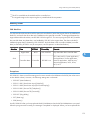
Model S-C4
Machine Code:
D067/D068/D069/D072
FIELD SERVICE MANUAL
January, 2009
Subject to change
Important Safety Notices
Prevention of Physical Injury
1. Be sure that the power cord is unplugged before disassembling or assembling parts of the copier or
peripherals.
2. The wall outlet should be near the copier and easily accessible.
3. Note that electrical voltage is supplied to some components of the copier and the paper tray unit even
while the main power switch is off.
4. If any adjustment or operation check has to be made with exterior covers off or open while the main
switch is turned on, keep hands away from electrified or mechanically driven components.
5. If you start a job before the copier completes the warm-up or initializing period, keep hands away
from the mechanical and electrical components until job execution has started. The copier will start
making copies as soon as warm-up or initialization is finished.
6. The inside and the metal parts of the fusing unit become extremely hot while the copier is operating.
Be careful to avoid touching those components with your bare hands.
Health Safety Conditions
Toner and developer are nontoxic, but getting either of these into your eyes may cause temporary eye
discomfort. Try to remove with eye drops or flush with water. If material remains in eye or if discomfort
continues, get medical attention.
Observance of Electrical Safety Standards
The copier and its peripherals must be installed and maintained by a customer service representative who
has completed the training course on those relevant models.
• Keep the machine away from flammable liquids, gases, and aerosols. A fire or an explosion might
occur if this precaution is not observed.
Lithium Batteries
Incorrect replacement of lithium battery(s) on the FCU, controller board and memory board unit may pose
risk of explosion. Replace only with the same type or with an equivalent type recommended by the
manufacturer. Discard used batteries in accordance with the manufacturer's instructions.
1
Safe and Ecological Disposal
1. Do not incinerate toner bottles or used toner. Toner dust may ignite suddenly if exposed to an open
flame.
2. Dispose of used toner, developer, and organic photoconductors in accordance with local regulations.
(These are nontoxic supplies.)
3. Dispose of replaced parts in accordance with local regulations.
4. When keeping used lithium batteries in order to dispose of them later, do not put more than 100
batteries per sealed box. Storing larger numbers or not sealing them apart may lead to chemical
reactions and heat build-up.
Laser Safety
The Center for Devices and Radiological Health (CDRH) prohibits the repair of laser-based optical units
in the field. The optical housing unit can only be repaired in a factory or at a location with the requisite
equipment. The laser subsystem is replaceable in the field by a qualified Customer Engineer. The laser
chassis is not repairable in the field. Customer engineers are therefore directed to return all chassis and
laser subsystems to the factory or service depot when replacement of the optical subsystem is required.
• Use of controls not specified in this manual, or performance of adjustments or procedures not specified
in this manual, may result in hazardous radiation exposure.
WARNING FOR LASER UNIT
• Turn off the main switch before attempting any of the procedures in the Laser Unit section. Laser
beams can seriously damage your eyes.
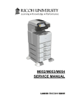
CAUTION MARKING:
2
Symbols and Abbreviations
This manual uses several symbols and abbreviations. The meaning of those symbols and abbreviations is
as follows:
See or Refer to
Clip ring
E-ring
Screw
Connector
Clamp
SEF
Short Edge Feed
LEF
Long Edge Feed
-
Core Technology manual
Cautions, Notes, etc.
The following headings provide special information:
• Failure to obey warning information could result in serious injury or death.
• Obey these guidelines to ensure safe operation and prevent minor injuries.
• This information provides tips and advice about how to best service the machine.
3
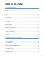
TABLE OF CONTENTS
Important Safety Notices...................................................................................................................................1
Prevention of Physical Injury..........................................................................................................................1
Health Safety Conditions...............................................................................................................................1
Observance of Electrical Safety Standards.................................................................................................1
Lithium Batteries..............................................................................................................................................1
Safe and Ecological Disposal.......................................................................................................................2
Laser Safety.....................................................................................................................................................2
Symbols and Abbreviations...............................................................................................................................3
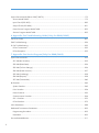
1. Product Information
Specifications....................................................................................................................................................11
Machine Configuration....................................................................................................................................12
Mainframe (Basic: D067/D072)..............................................................................................................12
Mainframe (F/SPF: D068/D069).............................................................................................................13
System Components (For D068/D069)...................................................................................................14
Overview..........................................................................................................................................................16
Component Layout.......................................................................................................................................16
Electrical Components.................................................................................................................................18
Paper Path....................................................................................................................................................21
Drive Layout..................................................................................................................................................22
Guidance for Those Who are Familiar with Predecessor Products..............................................................24
2. Installation
Installation Cautions.........................................................................................................................................25
Installation Requirements.................................................................................................................................26
Environment..................................................................................................................................................26
Machine Level..............................................................................................................................................26
Minimum Operational Space Requirements.............................................................................................27
Power Requirements....................................................................................................................................28
Copier...............................................................................................................................................................29
Accessory Check..........................................................................................................................................29
Optional Handset (Only for D068/D069)..............................................................................................36
Paper Tray Unit.................................................................................................................................................39
Accessory Check..........................................................................................................................................39
Installation Procedure..................................................................................................................................39
4
Paper Tray Unit Heater....................................................................................................................................42
Accessory Check..........................................................................................................................................42
Installation Procedure..................................................................................................................................43
ARDF (B872)....................................................................................................................................................50
Accessory Check..........................................................................................................................................50
Installation Procedure..................................................................................................................................50
USB 2.0/SD Slot Type B.................................................................................................................................57
Accessory Check..........................................................................................................................................57
Installation Procedure..................................................................................................................................57
Testing the SD Card/USB Slot....................................................................................................................63
Optional Paper Tray Grip Handle..................................................................................................................65
Accessories...................................................................................................................................................65
Printer/Scanner Unit........................................................................................................................................67
Accessory Check..........................................................................................................................................67
Installation Procedure..................................................................................................................................68
Controller Options............................................................................................................................................73
Overview......................................................................................................................................................73
PostScript3 Installation................................................................................................................................73
Wireless LAN (IEEE 802.11a/g) Installation...........................................................................................74
IEEE 1284 Installation.................................................................................................................................76
VM Card Type L (D467).............................................................................................................................77
Gigabit Ethernet...........................................................................................................................................78
HDD Option (D467, only for D067/D068)............................................................................................79
DataOverwriteSecurity Unit Type I (D362)...............................................................................................81
HDD Encryption Unit (D377)......................................................................................................................84
3. Preventive Maintenance
Maintenance Tables........................................................................................................................................89
How to Clear the PM Counter.........................................................................................................................90
4. Replacement and Adjustment
Precautions........................................................................................................................................................91
General.........................................................................................................................................................91
Lithium Batteries............................................................................................................................................91
Halogen-free Cable....................................................................................................................................91
5
Special Tools and Lubricants...........................................................................................................................92
Exterior Covers and Operation Panel............................................................................................................93
Rear Cover...................................................................................................................................................93
Copy Tray.....................................................................................................................................................93
Scale Plate (D067 only)..............................................................................................................................94
Operation Panel and Upper Covers..........................................................................................................95
Right Door.....................................................................................................................................................96
Bypass Tray..................................................................................................................................................96
Platen Cover Sensor....................................................................................................................................97
Scanner Unit.....................................................................................................................................................98
Exposure Glass............................................................................................................................................98
Lens Block.....................................................................................................................................................99
Exposure Lamp, Lamp Stabilizer Board.....................................................................................................99
Scanner Motor...........................................................................................................................................100
Scanner HP Sensor....................................................................................................................................102
Scanner Alignment Adjustment.................................................................................................................102
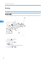
Fusing..............................................................................................................................................................104
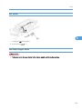
Fusing Unit..................................................................................................................................................104
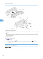
Exit Sensor..................................................................................................................................................105
Hot Roller Stripper Pawls..........................................................................................................................105
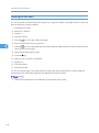
Hot Roller and Fusing Lamp......................................................................................................................106
Thermoswitches and Thermistor...............................................................................................................108
Pressure Roller............................................................................................................................................109
Checking the NIP band.............................................................................................................................110
PCU and Quenching Lamp...........................................................................................................................111
PCU.............................................................................................................................................................111
Quenching Lamp.......................................................................................................................................112
Exhaust Fan and Main Motor.......................................................................................................................113
Exhaust Fan................................................................................................................................................113
Main Motor...............................................................................................................................................114
Paper Feed.....................................................................................................................................................115
Paper Feed Roller and Friction Pad.........................................................................................................115
Paper End Sensor......................................................................................................................................116
6
Registration Sensor....................................................................................................................................116
Bypass Paper End Sensor.........................................................................................................................117
Bypass Feed Roller....................................................................................................................................118
Bypass Feed Clutch and Friction Pad......................................................................................................119
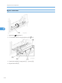
Paper Feed and Registration Clutches.....................................................................................................120
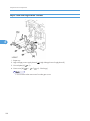
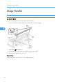
Image Transfer...............................................................................................................................................122
Transfer Roller............................................................................................................................................122
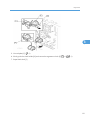
ID Sensor and Duplex Roller....................................................................................................................123
Discharge plate.........................................................................................................................................124
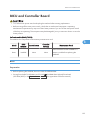
BICU and Controller Board..........................................................................................................................125
BICU...........................................................................................................................................................125
Controller Board (F/SPF models: D068/D069)...................................................................................127
Other Replacements......................................................................................................................................132
Duplex Motor............................................................................................................................................132
High-Voltage Power Supply Board ........................................................................................................133
PSU.............................................................................................................................................................134
Contact-Release Solenoid........................................................................................................................135
Toner Supply Clutch..................................................................................................................................135
FCU (For D068/D069)...........................................................................................................................136
Laser Unit........................................................................................................................................................139
Location of the Caution Decal..................................................................................................................139
Laser Unit....................................................................................................................................................139
LD Unit and Polygon Mirror Motor..........................................................................................................140
ARDF...............................................................................................................................................................141
ARDF...........................................................................................................................................................141
DF Rear Cover...........................................................................................................................................142
Original Feed Unit.....................................................................................................................................142
Separation Roller.......................................................................................................................................143
DF Drive Board..........................................................................................................................................143
Original Set and DF Inverter Sensor........................................................................................................144
DF Registration and DF Exit Sensor..........................................................................................................145
DF Feed Motor..........................................................................................................................................146
DF Transport Motor...................................................................................................................................147
7
DF Feed Clutch..........................................................................................................................................148
Adjusting Copy Image Area.........................................................................................................................149
Printing........................................................................................................................................................149
Scanning....................................................................................................................................................151
DF Image Adjustment................................................................................................................................154
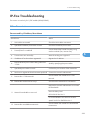
5. Troubleshooting
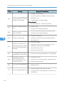
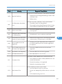
Service Call Conditions.................................................................................................................................157
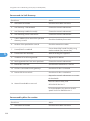
Electrical Component Defects.......................................................................................................................158
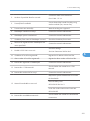
Card Save Function.......................................................................................................................................159
Overview....................................................................................................................................................159
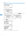
Procedure...................................................................................................................................................159
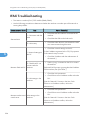
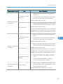
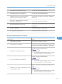
Fax Troubleshooting Guide (Only For D068/D069)................................................................................162
6. System Maintenance Reference
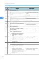
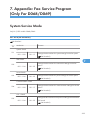
Service Program.............................................................................................................................................163
SP Tables....................................................................................................................................................163
Using SP and SSP Modes.........................................................................................................................163
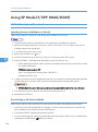
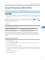
Using SP Mode (F/SPF: D068/D069).......................................................................................................166
NVRAM Data Upload/Download..........................................................................................................166
Firmware Update Procedure....................................................................................................................167
Test Pattern Print (SP5-902-001).............................................................................................................172
Memory Clear...........................................................................................................................................175
Machine No. Setting (SP5-811-001).....................................................................................................176
SMC Print (SP5-990)................................................................................................................................177
ID Sensor Error Analysis (SP2-221)........................................................................................................177
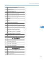
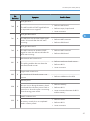
Using SP Mode (Basic: D067/D072)........................................................................................................179
NVRAM Data Upload/Download (SP5-824/825).............................................................................179
Firmware Update Procedure....................................................................................................................180
Test Pattern Print (SP5-902-001).............................................................................................................181
SMC Print (SP5-990)................................................................................................................................184
Serial Number Input (SP5-811-001)......................................................................................................184
Memory Clear...........................................................................................................................................185
ID Sensor Error Analysis (SP2-221)........................................................................................................186
Fax Service Tables (Only For D068/D069)..............................................................................................188
8
INDEX...........................................................................................................................................................189
9
10
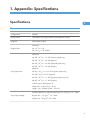
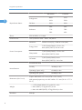
1. Product Information
Specifications
1
See "Appendices" for the following information:
• General Specifications
• Supported Paper Sizes
11
1. Product Information
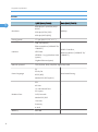
Machine Configuration
1
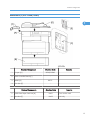
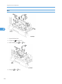
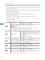
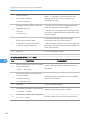
Mainframe (Basic: D067/D072)
Standard Component
1
Copier [A]
Optional Components
2
500-Sheet Paper Feed Unit [B]
Standard/Optional Component
3
12
ARDF [C]
Machine Code
D067/D072
Machine Code
B421
Machine Code
B872
Remarks
Remarks
Two can be used.
Remarks
• Standard for D072
• Optional for basic
Machine Configuration
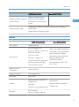
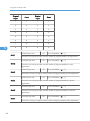
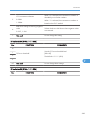
Mainframe (F/SPF: D068/D069)
1
Standard Component
1
Copier [A]
2
GW Controller Board [C]
3
ARDF [D]
4
Fax Unit [E]
Optional Components
Machine Code
Remarks
D068/D069
-
-
-
B872
-
-
-
Machine Code
Remarks
5
500-sheet Paper Feed Unit [B]
B421
Two can be used.
6
Handset [F]
B433
NA only
13
1. Product Information
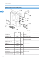
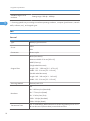
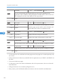
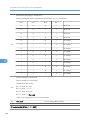
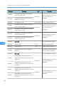
System Components (For D068/D069)
1
Item
Controller Box
14
Machine Code
Remarks
-
[A]
Standard
USB2.0/SD Slot
D467
[B]
Option only for D069
Printer/Scanner unit
D468
[C]
HDD Encryption Unit
D377
[C]
PostScript 3
D468
[C]
Data Overwrite Security
Unit
D362
[C]
VM Card
D467
[D]
IEEE 1284
B679
[E]
Wireless LAN
M344
[E]
Gigabit Ethernet Board
G874
[E]
SD card for the Printer/Scanner Unit
Standard only for D069
One from the three
-
One from the four
Machine Configuration
RAM DIMM
G332
[F]
Distributed with the printer/scanner unit
HDD
D362
[G]
-
1
15
1. Product Information
Overview
1
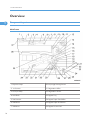
Component Layout
Mainframe
16
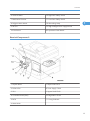
1. Exposure Lamp
20. ID (Image Density) Sensor
2. 1st Scanner
21. Registration Roller
3. CCD (on SBU)
22. Registration Sensor
4. Lens Block
23. Bypass Tray
5. 2nd Scanner
24. Bypass Paper Feed Roller
6. 2nd Mirror
25. Bypass Paper End Sensor
7. 3rd Mirror
26. Bypass Friction Pad
Overview
8. Platen Cover Sensor
27. Mixing Augers
9. Exposure Glass
28. (Main) Friction Pad
10. Exit Roller
29. Paper Feed Roller
11. Exit Sensor
30. Paper End Sensor
12. Scanner Motor
31. TD (Toner Density) Sensor
13. Hot Roller
32. Bottom Plate
14. Pressure Roller
33. Polygon Mirror Motor
15. Cleaning Blade
34. Laser Unit
16. OPC Drum
35. Toner Supply Bottle (or THM)
17. Discharge Plate
36. Toner Collection Coil
18. Transfer Roller
37. Scanner HP Sensor
1
19. Development Roller
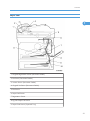
ARDF
1. Separation Roller
7. Exit Roller
2. Paper Feed Roller
8. Exit Sensor
3. Pick-up Roller
9. Registration Sensor
4. Original Set Sensor
10. Registration Roller
5. Inverter Roller
11. Inverter Sensor
17
1. Product Information
6. Junction Gate
1
12. Transport Roller
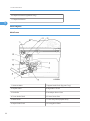
Electrical Components
Electrical Components 1
18
1. Lens Block
11. ID (Image Density) Sensor
2. Exposure Lamp
12. Registration Sensor
3. Lamp Stabilizer Board
13. Paper End Sensor
4. Scanner HP Sensor
14. Toner Density Sensor
5. Platen Cover Sensor
15. Bypass Paper End Sensor
Overview
6. Scanner Motor
16. Right Door Safety Switch
7. Mechanical Counter
17. Front Door Safety Switch
8. Polygon Mirror Motor
18. Quenching Lamp
9. LD Unit
19. High-Voltage Power Supply Board
10. Exit Sensor
20. Operation Panel Board
1
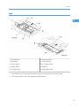
Electrical Components 2
1. Duplex Motor
7. Paper Feed Clutch
2. Exhaust Fan
8. Toner Supply Clutch
3. PSU
9. Bypass Feed Clutch
4. Controller Board (GW)
10. Registration Clutch
5. BICU
11. Fusing Solenoid
6. Main Motor
19
1. Product Information
ARDF
1
20
1. DF Feed Clutch
6. DF Feed Motor
2. Registration Sensor
7. Inverter Sensor
3. Exit Sensor
8. DF Drive Board
4. Left Cover Sensor
9. Junction Gate Solenoid
5. DF Transport Motor
10. Original Set Sensor
Overview
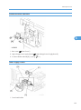
Paper Path
1
1. Original Registration Sensor (Document Feeder)
2. Exit Senor (Document Feeder)
3. Inverter Sensor (Document Feeder)
4. Original Set Sensor (Document Feeder)
5. Exit Sensor
6. Paper Path Sensor
7. Registration Sensor
8. By-pass Paper End Sensor
9. Paper Feed Sensor (Optional Tray)
21
1. Product Information
10. Paper End Sensor (Optional Tray)
11. Paper End Sensor
1
Drive Layout
Mainframe
22
1. Scanner Motor
7. Bypass Feed Clutch (By-pass Tray)
2. Duplex motor
8. Registration Clutch
3. Exit Roller
9. Developer Driver Gear
4. Toner Bottle Clutch
10. Drum Drive Gear
5. Main Motor
11. One-way Gear (Duplex Unit)
6. Paper Feed Clutch
12. Fusing Drive Gear
Overview
ARDF
1
1. DF Feed Motor
6. Separation Roller
2. Feed Roller
7. Transport Roller
3. Pick-up Roller
8. DF Transport Motor
4. Inverter Roller
9. Exit Roller
5. DF Feed Clutch
10. Registration Roller
• DF Feed Motor: Drives the feed, separation, pick-up, and transport and inverter rollers.
• DF Transport Motor: Drives the registration and exit rollers.
23
1. Product Information
1
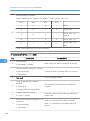
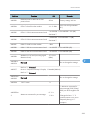
Guidance for Those Who are Familiar with
Predecessor Products
The D067/D068/D069/D072 range of machines is the successor model to the B262/B292/B284/
B288 range of machines. If you have experience with the predecessor line, the following information may
be of help when you read this manual.
Differences from Predecessor Products
D067/D068/D069/D072
B262/B292/B284/B288
Following controller options were
added.
Controller Option
• HDD (80GB)
-
• USB2.0/SD Slot
• Gigabit Ethernet
SD Card Slots
Copying Speed
24
2 slots
17ppm: Memory copy
16ppm: ADF 1 to 1
3 slots
16ppm
2. Installation
Installation Cautions
• Before installing an optional unit, do the following:
2
• Print out all messages stored in the memory, all user-programmed items, and a system parameter list.
• If there is a printer option on the machine, print out all data in the printer buffer.
• Turn off the main switch and disconnect the power cord, the telephone line, and the network cable.
25
2. Installation
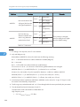
Installation Requirements
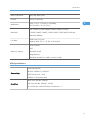
Environment
2
–Temperature and Humidity Chart–
• Temperature Range: 10°C to 32°C (50°F to 89.6°F)
• Humidity Range: 15% to 80% RH
• Ambient Illumination: Less than 1,500 lux (Do not expose to direct sunlight.)
• Ventilation: Room air should turn over at least 3 times/hr/person
• Ambient Dust: Less than 0.1 mg/m3
• Do not install the machine where it will be exposed to direct sunlight or to direct airflow (from a fan,
air conditioner, air cleaner, etc.).
• Do not install the machine where it will be exposed to corrosive gas.
• Place the machine on a firm and level base.
• Do not install the machine where it may be subjected to strong vibration.
Machine Level
Front to back:
26
Within 5 mm (0.2") of level
Installation Requirements
Right to left:
Within 5 mm (0.2") of level
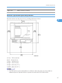
Minimum Operational Space Requirements
Place the machine near the power source, providing clearance as shown.
2
A: Front – 750 mm (29.6")
B: Left – 100 mm (3.9")
C: Rear – 100 mm (3.9")
D: Right – 100 mm (3.9")
E: Depth – 450 mm (17.7")
F: Width – 485 mm (19.1")
• The 750-mm front space indicated above is sufficient to allow the paper tray to be pulled out.
Additional space is required to allow an operator to stand at the front of the machine.
27
2. Installation
• Actual minimum space requirement for left, rear, and right sides is 10mm (0.4") each, but note that
this will not allow room for opening of the bypass tray, right door, platen cover, or ARDF unit.
Power Requirements
2
• Make sure that the wall outlet is near the machine and easily accessible. After completing installation,
make sure the plug fits firmly into the outlet.
• Avoid multiple connections to the same power outlet.
• Be sure to ground the machine.
Input voltage:
North America:
110 – 120 V, 60 Hz, 8 A
Europe:
220 – 240 V, 50/60 Hz, 4 A
Image quality guaranteed at rated voltage ± 10%.
Operation guaranteed at rated voltage ± 15%.
28
Copier
Copier
Accessory Check
2
Basic Model (D067/D072)
Description
Q’ty
NECR (-15, -27)
1
EU Safety Sheet (-27)
1
Paper Size Decal (-15, -27)
1
Operating Instructions – Book: Fax (-15, -27)
1 set
Operating Instructions – Book (-15, -27)
1 set
Operating Instructions – CD ROM (-15, -27)
1 set
EMC caution Sheet (-27)
1
Fax Model (D068)/ Printer/Scanner and Fax Model (D069)
Description
Q’ty
NECR (-17)
1
EU Safety Sheet (-27)
1
Paper Size Decal (-17, -27, -29)
1
Operating Instructions – Book (-17, -27, -29)
1 set
Operating Instructions – CD ROM (-17, -27, -29)
1 set
Handset Bracket (-17)
1
Screw for Handset Bracket (-17)
2
Modular Cable (-17)
1
Operating Instructions – Book: Fax (-17, -27, -29)
1 set
29
2. Installation
Description
2
Connecter Cover for TEL (-17)
1
Ferrite Core for TEL Line
1
Ferrite Core (-17, -27, -29)
1
EMC Caution Sheet (-27)
1
EULA Sheet (-17, -27, -29)
1
Caution Decal (-17, -27, -29)
1
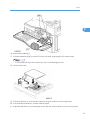
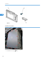
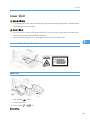
Installation Procedure
• Make sure that the copier remains unplugged during installation.
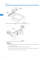
1. Remove the all strips of tape.
2. Remove the bag [A], SMC and A3 sheet of paper on the exposure glass.
30
Q’ty
Copier
2
3. Remove the spacing wedge [B].
4. Remove the three scanner lock pins. (A tag is hanging from each pin.) To remove: Grasp the base of
the pin [C], turn the pin 90 degrees, and pull it down and out.
5. Remove the tags from the pins.
6. Break each pin off the base [C].
7. Discard the pin part [D].
8. Set each base [C] back into its original hole, turning it 90° to lock it into place. (Be sure to do this for
all three pins.)
31
2. Installation
2
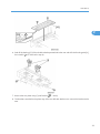
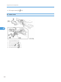
9. Open the front door [E].
10. Lift lever [F], press in on latch [G] and pull the bottle holder [H] out. (You do not need to pull it completely
out of the machine.)
11. Take a new bottle of toner, and shake it several times.
12. Remove the outer cap [I].
• Do not remove the inner cap [J].
13. Load the bottle on the holder.
• Do not forcefully turn the toner bottle on the holder. After you turn on the main power switch, the
copier sets the bottle in place.
14. Push the bottle holder back into the machine.
15. Press the latch [K] down to lock the holder.
32
Copier
2
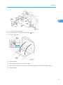
16. Remove the padding [L].
17. Pull each tabbed strip [M] out of the PCU with one hand, supporting the PCU with the other.
• Do not pull both strips at the same time, as this could damage the PCU.
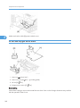
18. Close the front door.
19. Pull out the paper tray, and remove the tape securing the end fence in the compartment.
20. Push the bottom plate down, and then load the paper.
21. Adjust the side fences. If you load paper shorter than A4, set the end fence in the correct position.
33
2. Installation
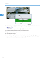
22. Push the tray back into the copier.
2
23. Attach the appropriate Brand Decal to the center [N] of the front door if necessary.
24. Attach the appropriate tray number decal and paper-size decal to the paper tray [O].
25. Install optional units (if any).
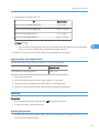
26. Attach the ferrite core [P] to the network cable when connecting the cable.
27. Attach the ferrite core to the telephone line in the same manner as step 26 (only for D068/D069).
28. Connect the telephone line to the "LINE" jack (only for D068/D069).
• The end of the ferrite core must be about 10 cm (4") from the end of the cable.
29. Plug in the machine and turn on the main power switch.
34
Copier
30. Select the language used in the operation panel as necessary (
> Language).
For D068/D069: Interface settings
D068:
1. Start the SP mode.
2. Select SP5-985-001 (NIC setting) and change the setting value to "0" (OFF).
2
3. Select SP5-985-002 (USB setting) and change the setting value to "0" (OFF).
4. Turn the main switch off and on.
D069:
1. Start the SP mode.
2. Select SP5-985-001 (NIC setting) and change the setting value to "1" (ON).
3. Select SP5-985-002 (USB setting) and change the setting value to "1" (ON).
4. Turn the main switch off and on.
For D068/D069: Copier settings
1. Start the SP mode.
2. Select SP5-801-001 and execute the initialization.
3. Exit the SP mode, and then start the UP mode.
4. Select the "@Remote Service" ("User Tool" > "System Settings > Administrator Tools" > "Extended
Security" > @Remote Service") and select "Prohibit".
5. Exit the UP mode, and then start the SP mode.
6. Select SP5-870-003 and execute initialization for @Remote.
7. Select SP5-907-001 and specify the "Plug & Play".
8. Select SP5-870-001 and execute writing certification for @Remote S.
9. Select SP5-302-002 and specify the time zone.
10. Select SP5-307-001, 003, and 004 and specify the daylight-saving-time settings.
11. Exit the SP mode and turn the main switch off and on.
12. Start the UP mode.
13. Specify the date and time with "Set Date" or "Set Time" (User Tool" > "System Settings" > "Set Date"
or "Set Time").
14. Turn the main switch off and on.
15. Check the operations.
35
2. Installation
16. Make a full size copy, and check if the side-to-side and leading edge registrations are correct. If they
are not, adjust the registrations.
For D068/D069: Fax Settings
2
Initializing the Fax unit
When you press the Fax key for the first time after installation, the error "SRAM problem occurred / SRAM
was formatted" will show on the LCD for initializing the program of the fax unit. Turn the main power switch
off/on to clear the error display.
• If another error occurs after initialization, this can be a functional problem.
1. Select fax SP1-101-016 and specify the country code.
2. Select fax SP3-101-001 and specify the service station.
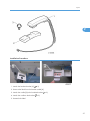
Optional Handset (Only for D068/D069)
Accessory Check
Check that you have the components and accessories.
No.
Description
Q’ty
1
Handset
1
2
Handset cradle
1
3
Screws
2
4
Handset manual
1
• The handset bracket is not included in the optional handset kit. The bracket is provided as an accessory
of the copier.
36
Copier
2
Installation Procedure
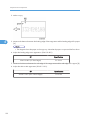
1. Attach the handset bracket [A] ( x 2)
2. Remove the label from the handset cradle [B].
3. Attach the cradle [B] to the handset bracket ( x 2).
4. Attach the cradle to the bracket ( x 2).
5. Reattach the label.
37
2. Installation
2
• The bracket is an accessory of the copier.
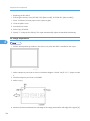
6. Set the handset on the cradle.
7. Connect the handset cable to the “TEL” jack and set the telephone cable [A] as shown above.
38
Paper Tray Unit
Paper Tray Unit
Accessory Check
Confirm that you have these accessories.
Description
1. Paper-size decals
Q’ty
2
1 sheet
2. Installation Procedure (for service technicians)
1
3. Installation Procedure (for users)
1
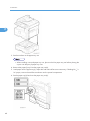
Installation Procedure
• Unplug the main machine's power cord before starting the following procedure.
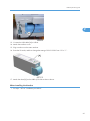
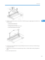
1. Remove the tape at [A], and the tape and cardboard at [B].
2. Pull the paper tray part way out of the unit, remove the tape and cardboard at [C], and push the tray
back in.
39
2. Installation
2
3. Set the machine on the paper tray unit.
• When installing a second paper tray unit, place on the first paper tray unit before placing the
copier onto the pair pf paper tray units
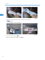
4. Remove the paper(s) tray from the paper tray unit(s).
5. Load paper into the paper tray(s). Adjust the side and end fences as necessary. If loading 81/2"x
14" paper, remove the end fence and set it into the special compartment.
6. Set the paper tray(s) back into the paper tray unit(s).
40
Paper Tray Unit
7. Stick on the appropriate tray-number decal(s) and paper-size decal(s), at the locations indicated in
the illustration.
2
41
2. Installation
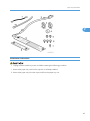
Paper Tray Unit Heater
The paper tray unit heater is installed only for the first paper tray unit.
2
Accessory Check
Confirm that you have the accessories listed below.
Description
42
Q’ty
1. Grounding wire
1
2. Relay harness
1
3. Clamps
2
4. Ferrite core
1
5. Heater fastening screws
2
6. PTU fastening screws
3
7. Grounding screw
1
8. Decal for copier
1
9. Decal for paper tray unit
1
10. Tie wrap
1
Paper Tray Unit Heater
2
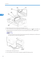
Installation Procedure
• Unplug the main machine's power cord before starting the following procedure.
1. Remove the paper tray unit from the copier if it is already installed.
2. Remove the paper trays from the copier and from the paper tray unit.
43
2. Installation
2
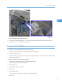
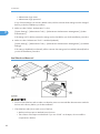
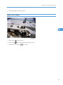
3. Remove the ground screw [1] at the rear of the paper tray unit.
4. Fasten the heater [2] and the supplied ground wire [3] to the paper tray unit ( x 3). Note that [1] is
the ground screw you removed in the previous step and [4] and [5] are the two supplied heater
fastening screws.
• Be sure to position the ground wire [3] and heater harness [6] so that they are out of the way of
the copier when you set it on the paper tray unit.
5. Set the copier on the paper tray unit.
6. Screw the paper tray unit into place using three supplied PTU fastening screws.
44
Paper Tray Unit Heater
2
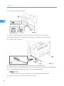
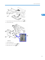
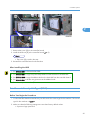
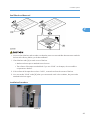
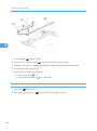
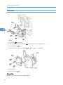
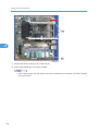
7. Open the front door and remove the copy tray [7] ( ×1).
8. Close the front door.
1. Open the right cover
2. Remove the interface cover [8] ( x 1).
3. Remove the rear cover [9] ( x 5).
45
2. Installation
2
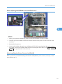
4. For D068/D069: Remove the upper left cover [10].
5. For D068/D069: Remove the controller box [11] (
6. Remove the support bracket [12] ( x 3).
46
x 1,
x 6).
Paper Tray Unit Heater
2
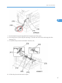
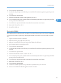
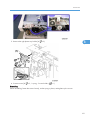
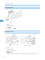
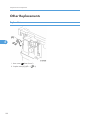
7. Pass the heater harness through the hole [15] at the rear of the copier.
8. Pass relay harness [16] through the opening [17] (at the rear of the PSU) and through the other
opening [15].
9. Connect the relay harness to the heater's harness [18].
10. Pull the relay harness back into the copier.
47
2. Installation
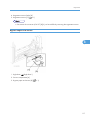
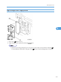
11. Attach the ferrite core [19] over the relay harness.
12. Push the ferrite core back so that it is over the heater's harness.
13. Wrap the heater's harness once around the ferrite core [20].
14. Locate the ferrite core at the rear [24] of the copier behind the rear clamps.
2
15. Secure the ferrite core with the supplied tie wrap [21].
16. Clip off the excess length of the tie wrap.
17. Connect the relay harness connector [22] to the large connector at the front center of the PSU.
18. Screw the ground wire [23] to the PSU bracket with the included grounding screw.
19. Attach the clamps [24] to the PSU bracket.
20. Attach the heater harness though the clamps.
21. Position the harness so that the front clamp is between the two bindings [25] on the harness.
22. Fasten the clamps.
23. Pull the excess length of the heater's harness out the opening at the rear.
• Be sure that the harness passes on the side of the grounding plate at the bottom of the opening.
(The front of the grounding plate must remain clear.)
24. Arrange the excess harness length so that it sits beneath the FCU cover plate.
25. Attach the caution decals to the locations shown in the illustration.
48
Paper Tray Unit Heater
2
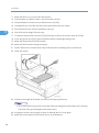
26. Reassemble the copier.
27. Plug in the power cord, and check the operation.
49
2. Installation
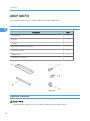
ARDF (B872)
This procedure explains how to install the ARDF for the Basic model: D067.
2
Accessory Check
Description
Q’ty
1. Stud Screw
1
2. Screw
1
3. Clamp
1
4. DF Exposure Glass with Mylar
1
5. Left Scale Guide
1
-. Platen Sheet
1
-. Installation Procedure
1
Installation Procedure
• Unplug the main machine's power cord before starting the following procedure.
50
ARDF (B872)
2
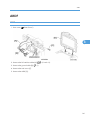
1. Unpack the ARDF and remove the packing tape from the bottom of the ARDF body.
2. Open the right door [A].
3. Remove the interface cover [B] ( x 1) and rear cover [C] ( x 5).
51
2. Installation
2
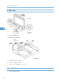
4. Remove the left guide [D] ( x 2) and scanner left cover [E] (hook x 2).
5. Place the DF exposure glass [F] on the glass holder.
• When installing the DF exposure glass, make sure that the side of the DF exposure glass with
two black points faces down.
• Do not hold the Mylar strip when installing the DF exposure glass.
• Make sure that there is no gap between the two Mylar strips and the scanner frame. If there is
any gap between them, dust may fall into the scanner unit.
52
ARDF (B872)
2
6. Peel off the backing [G] of the double-sided tape attached to the rear side of the left scale guide [H],
then install it ( x 2 removed in step 4).
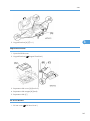
7. Remove the two platen stays [I] and bracket ( x 1 each).
8. The bracket is attached to the platen stay of the rear left side. Make sure to remove the bracket at this
time.
53
2. Installation
2
9. Mount the DF [J] on the copier as shown.
10. Secure the screw [K].
11. Attach the clamp [L].
12. Connect two I/F cables [M] to CN109 and CN110 on the BICU, and secure the ground cable [N]
( x 1, x 2).
• Make sure that the I/F cable of ARDF is clamped between the two binds [O].
• Reinstall the scanner left side cover removed in step 4.
54
ARDF (B872)
2
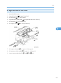
13. Cut the cutout [P] with nippers.
14. Reinstall the rear cover and connector cover ( x 6).
15. Close the right door.
16. Open the ARDF.
17. Place platen sheet [Q] on the exposure glass.
18. Line up the rear left corner of the platen sheet flush against corner [R] on the exposure glass.
19. Close the ARDF.
55
2. Installation
2
20. Check that the groove [S] of the ARDF is aligned with the groove [T] of the left scale on the scanner.
• The difference in position between [S] and [T] must be within ± 0.5 mm.
21. Reinstall the platen sheet if both grooves are not aligned correctly.
22. Plug in and turn on the main power switch.
23. Check the ARDF operation.
24. Make a full size copy. Then check to make sure the side-to-side and leading edge registrations are
correct. If they are not, adjust the side-to-side and leading edge registration (refer to "DF Image
Adjustment" in the section "Replacement and Adjustment").
56
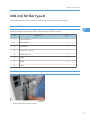
USB 2.0/SD Slot Type B
USB 2.0/SD Slot Type B
This procedure explains how to install the USB 2.0/SD Slot for the SPF model (D069).
Accessory Check
2
Check the quantity and condition of the accessories against the following list.
No.
Description
Q’ty
1
USB2.0/SD Slot
1
2
Ground Plate
1
3
USB Cable
1
4
Screw: M3 x 6 blue
1
5
Screw: M3 x 8
2
6
Screw:
1
7
Clamp
1
8
Decal
1
Installation Procedure
1. Remove the USB connect cover [A].
57
2. Installation
2
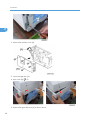
2. Remove the interface cover [A].
3. Open the right door [A].
4. Rear cover [B] ( x 5)
5. Remove the upper left cover [A] as shown above.
58
USB 2.0/SD Slot Type B
2
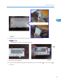
6. Make three holes in the upper left cover with a screwdriver as shown above.
• Smooth the three holes in the upper left cover.
7. Attach the ground plate [A].
8. Secure the USB2.0/SD Slot [B] with the upper left cover as shown above ( x 1: M3 x 6 blue,
2: M3 x 8).
x
59
2. Installation
2
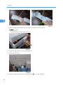
9. Make a clamp hole the upper left cover with a screwdriver as shown above.
• Smooth the hole in the upper left cover.
10. Attach the upper left cover [A] to the mainframe.
11. Attach the rear cover.
12. Attach the cable clamp [A] to the upper left cover ( x 1) as shown above.
60
USB 2.0/SD Slot Type B
2
13. Connect the USB cable [A] to USB-A.
14. Attach the interface cover.
15. Plug in and turn on the main machine.
16. Enter the SP mode, and then change the setting of SP1013-001 from “0” to “1”.
17. Attach the decal [A] to the USB2.0/SD Slot as shown above.
When Installing the Handset
1. Do steps 1 to 8 in “installation procedure”.
61
2. Installation
2
2. Make two holes the upper left cover with a screwdriver as shown above.
• Smooth the holes in the upper left cover.
3. Attach the handset bracket [A] ( x 2)
4. Attach the cradle [B] to the handset bracket ( x 2)
62
USB 2.0/SD Slot Type B
2
5. Set the handset on the handset bracket.
6. Connect the handset cable to the “TEL” jack and set the telephone cable [A] as shown above.
7. Do steps 13 to 17 in “installation procedure”.
Testing the SD Card/USB Slot
1. Insert an SD card or USB memory device in the slot.
You can connect only one removable memory device at a time.
2. Close the media slot cover.
If you leave the cover open, static electricity conducted through an inserted SD card could cause the
machine to malfunction.
3. Make sure that no previous settings remain.
If a previous setting remains, press the [Clear Modes] key.
4. Place an original on the exposure glass.
5. Press [Store File].
6. Press [Store to Memory Device].
7. Press [OK].
8. Press the [Start] key.
When writing is complete, a confirmation message appears.
9. Press [Exit].
63
2. Installation
10. Remove the memory device from the media slot.
Do not remove the memory device while writing is in process.
2
64
Optional Paper Tray Grip Handle
Optional Paper Tray Grip Handle
The following procedure is for the paper tray for the main copier or optional paper tray unit.
Accessories
2
Check the accessories and their quantities against the table below.
No.
Description
Q’ty
1
Grip Handle
1
2
Screw (M3 x 10)
2
65
2. Installation
Installation Procedure
2
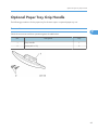
1. Remove the paper tray [A] from the main copier.
2. Turn the paper tray over to the opposite side.
3. Lower the paper tray grip handle [B] into the paper tray slot as shown, with the arrow in the above
illustration.
4. Attach the grip handle to the paper tray ( x 2).
• When attaching auxiliary handle (two screws attached from bottom), hold handle against front
of paper drawer (as screws are tightened) to ensure there is ensure the smallest gap between
back of handle and front of paper drawer.
5. Put the paper tray back into the machine.
66
Printer/Scanner Unit
Printer/Scanner Unit
This procedure explains how to install the printer/Scanner unit for the basic models (D067/D072).
Accessory Check
No.
Description
Q’ty
1
Screw M3 x 6
7
2
Controller Box
1
3
Printer Panel: NA (-15)
1
Printer Panel: EU (-27)
1
4
Multi-function Panel
1
5
Security Reference (-15)
1
Quick Reference Printer Guide (-15, -27)
1
Quick Reference Scanner Guide (-15, -27)
1
CD-ROM: Printer (-15)
1
CD-ROM: Scanner (-15, -27)
1
7
Interface Cover
1
8
FCC Decal (-15)
1
9
Ferrite Core
1
-
Installation Procedure
1
-
Sheet: EULA
1
-
Sheet: CAUTION
1
-
Decal - Power Source : OFF
1
6
2
67
2. Installation
2
Installation Procedure
• Unplug the machine power cord before starting the following procedure.
68
Printer/Scanner Unit
1. Open the right door [A].
2. Remove the interface cover [B] ( x 1)
3. Remove the rear cover [C] ( x 5).
4. Remove the bracket [D] at the rear left frame of the mainframe ( x 2).
5. Remove the scanner upper left cover [E].
2
6. Cut the opening [F] on the rear cover. This opening is for the network interfaces and the SD card slot
and the LAN cable.
• Do not cut the topmost opening [G].
7. Install the ground plate [A] ( x 2).
• Insert the upper and lower hooks in the openings [B], and fasten the upper screw first.
69
2. Installation
8. Install the controller box [C] ( x 6).
• Insert the bracket [D] into the frame. The connector on the controller box engages with the
connector on the BICU.
2
9. Install PostScript 3 as necessary.
10. Remove the front left cover [A] ( x 2).
11. Retain the screws and use them in the next step.
12. Install the multi-function panel [B] ( x 1, x 2).
13. Remove the panel cover [A].
14. Install the printer panel [B].
70
Printer/Scanner Unit
2
15. For the North America model only:
Attach the FCC decal [A] at the right-hand side of the USB connector on the controller box
16. Reassemble the whole copier.
17. Attach the ferrite core [A] to the network cable and attach the cable to the copier if a network cable
is used.
• The ferrite core must be attached next to the network cable connector [B].
18. Attach the “Power Source: OFF” decal [C] to the under of main power switch at the left side of the
machine as shown above.
19. Plug in the power cord, and turn on the main switch.
20. For the North America model only: Perform the interface settings.
1) Start the SP mode.
71
2. Installation
2) Select SP5-985-001 (NIC setting) and change the setting value to "1" (ON).
3) Select SP5-985-002 (USB setting) and change the setting value to "1" (ON).
4) Turn the main switch off and on.
21. Perform the Printer/Scanner settings.
2
1) Start the SP mode.
2) Select SP5-801-001 and execute the initialization.
3) Exit the SP mode, and then start the UP mode.
4) Select the "@Remote Service" ("User Tool" > "System Settings > Administrator Tools" > "Extended
Security" > @Remote Service") and select "Prohibit".
5) Exit the UP mode, and then start the SP mode.
6) Select SP5-870-003 and execute initialization for @Remote.
7) Select SP5-907-001 and specify the "Plug & Play".
8) Select SP5-870-001 and execute writing certification for `Remote.
9) Select SP5-302-002 and specify the time zone.
10) Select SP5-307-001, 003, and 004 and specify the daylight-saving-time settings.
11) Exit the SP mode and turn the main switch off and on.
12) Start the UP mode.
13) Specify the date and time with "Set Date" or "Set Time" (User Tool" > "System Settings" > "Set
Date" or "Set Time").
22. Turn the main switch off and on.
23. Check the operations.
72
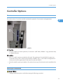
Controller Options
Controller Options
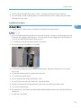
Overview
This machine has I/F card slots and SD card slots for optional I/F connections and applications.
2
I/F Card Slot
• Slot [A] is used for one of the optional I/F connections: (IEEE1284, IEEE802.11a/g (Wireless LAN)
or Gigabit Ethernet).
SD Card Slot
• Slot [1] is used for options provided on SD cards. The application SD card (HDD Encryption unit,
Overwrite Security Unit or PostScript3) should be installed in Slot 1. If more than one application is
to be used, move the applications to the same SD card with SP5873.
• Slot [2] is used for options provided on SD cards and servicing. The VM card must be installed in Slot
2.
PostScript3 Installation
• Unplug the machine power cord before starting the following procedure.
73
2. Installation
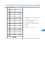
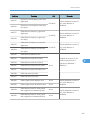
Accessories
Check the accessories and their quantities against the table below.Accessories
No.
2
Description
Q’ty
1
PostScript 3 Emulation SD Card (D468)
1
2
Decal
1
Installation Procedure
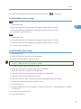
1. Install the PostScript3 SD card [A] into slot 1.
2. Turn on the main power switch.
3. Print out the configuration page (User Tools/ Counter > Printer Features > List/ Test Print), and then
check that this device is detected.
4. Attach the "Adobe PostScript3" decal to the front cover of the machine.
Wireless LAN (IEEE 802.11a/g) Installation
• Unplug the machine power cord before starting the following procedure.
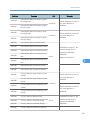
Accessories
Check the accessories and their quantities against the table below.Accessories
No.
1
74
Description
Wireless Adapter
Q’ty
1
Controller Options
No.
Description
Q’ty
2
Wireless LAN Card
1
3
LAN Card Cover
4
4
Caution Sheet
1
5
Label
1
2
Installation Procedure
1. Remove the interface cover [A] ( x 2).
2. Install the Wireless adaptor into I/F slot [B] ( x 2).
3. Install the Wireless LAN card in the wireless adaptor.
4. Attach the antenna cap to the wireless LAN card.
5. Turn on the main power switch.
6. Print out the configuration page (User Tools/Counter > Printer Features > List/Test Print), and then
check that this device is detected.
If reception is poor, you may need to move the machine:
• Make sure that the machine is not located near an appliance or any type of equipment that could
generate a strong magnetic field.
• Position the machine as close as possible to the access point.
75
2. Installation
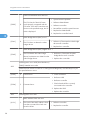
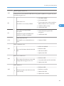
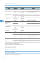
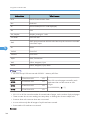
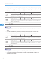
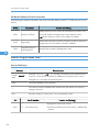
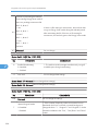
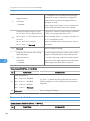
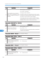
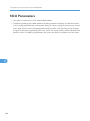
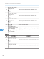
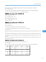
SP Mode Settings for IEEE 802.11a/g Wireless LAN
The following SP commands can be set for IEEE 802.11a/g
SP No.
2
Name
Function
5840 004
SSID
Used to confirm the current SSID setting.
5840 006
Channel MAX
Sets the maximum range of the channel settings for the country.
5840 007
Channel MIN
Sets the minimum range of the channel settings allowed for your
country.
5840 011
WEP Key Select
Used to select the WEP key (Default: 00).
5840 018
SSID Check
Used to check the SSID.
5840 020
WEP Mode
Used to display the maximum length of the string that can be
used for the WEP Key entry.
IEEE 1284 Installation
• Unplug the machine power cord before starting the following procedure.
Accessories
Check the accessories and their quantities against the table below.Accessories
No.
76
Description
Q’ty
1
IEEE1284 Interface Ass’y
1
2
UL Sheet
1
3
Caution Sheet
1
Controller Options
Installation Procedure
2
1. Remove the interface cover [A] ( x 2).
2. Install the IEEE 1284 board into I/F slot [B] ( x 2).
3. Turn on the main power switch.
4. Print out the configuration page (User Tools/Counter > Printer Features > List/Test Print), and then
check that this device is detected.
VM Card Type L (D467)
Accessories
Check the accessories and their quantities against the table below.Accessories
No.
Description
Q’ty
1
VM SD Card
1
2
Decal
1
77
2. Installation
Installation
2
1. Switch the machine off.
2. Insert the SD card [A] into SD Slot 2 (lower).
• This SD card must be inserted into Slot 2, the lower slot.
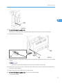
Gigabit Ethernet
• Unplug the main machine power cord before you do the following procedure.
1. Remove the I/F-slot cover [A] ( x 2).
2. Install the Gigabit Ethernet board (Knob-screw x 2) into the I/F-slot [B].
78
Controller Options
2
3. Attach one ferrite core [A] to the Ethernet interface cable, and then attach the other ferrite core [B]
about 10cm from the end of the Ethernet interface cable.
4. Connect the Ethernet interface cable to the Gigabit Ethernet port.
Make sure that the machine can recognize this option (see ‘Check All Connections’ at the end of this
section).
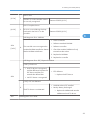
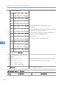
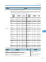
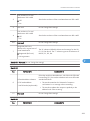
HDD Option (D467, only for D067/D068)
Component Check
No.
Description
Q’ty
1
HDD Unit
1
2
Screw
3
Keytop: Copy (Not used)
2
Keytop: Document Server (Not used)
2
Knob Screw (Not used)
3
3
-
79
2. Installation
2
Installation Procedure
1. Controller box cover [A] ( x 13)
80
Controller Options
2
1. Remove the screw [A] on the controller board.
2. Install the HDD unit [B] in the controller board ( x 3).
• The screw [A] is used in this step.
3. Reinstall the controller board in the machine.
After Installing the HDD
1. Do SP5832-001 to format the hard disk.
2. Do SP5853-001 to copy the preset stamp data from the firmware to the hard disk.
3. Do SP5846-040 to copy the address book to the hard disk from the controller board.
4. Do SP5846-041 to let the user get access to the address book.
5. Turn the main power switch off/on.
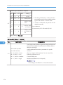
DataOverwriteSecurity Unit Type I (D362)
Before You Begin the Procedure
1. Confirm that the DataOverwriteSecurity unit SD card is the correct type for the machine. The correct
type for this machine is "Type I".
2. Make sure that the following settings are not at their factory default values:
• Supervisor login password
81
2. Installation
• Administrator login name
• Administrator login password
If any of these settings is at a factory default value, tell the customer these settings must be changed
before you do the installation procedure.
3. Make sure that “Admin. Authentication” is ON.
2
[System Settings] – [Administrator Tools] – [Administrator Authentication Management] - [Admin.
Authentication]
If this setting is OFF, tell the customer this setting must be ON before you do the installation procedure.
4. Make sure that “Administrator Tools” is enabled (selected).
[System Settings] – [Administrator Tools] – [Administrator Authentication Management] - [Available
Settings]
If this setting is disabled (not selected), tell the customer this setting must be enabled (selected) before
you do the installation procedure.
Seal Check and Removal
• You must check the box seals to make sure that they were not removed after the items were sealed in
the box at the factory before you do the installation.
1. Check the box seals [A] on each corner of the box.
• Make sure that a tape is attached to each corner.
• The surfaces of the tapes must be blank. If you see “VOID” on the tapes, do not install the
components in the box.
82
Controller Options
2. If the surfaces of the tapes do not show “VOID”, remove them from the corners of the box.
3. You can see the “VOID” marks [B] when you remove each seal. In this condition, they cannot be
attached to the box again.
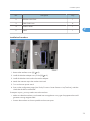
Installation Procedure
2
• Unplug the main machine power cord before you do the following procedure.
• You must install the DataOverwriteSecurity unit in SD Card slot 1. However, the Postscript option and
others are also installed in SD Card slot 1. You must do the "SD Card Appli Move" procedure first if
you want to install the Data Overwrite Security unit.
1. Turn off the main power switch if the machine is turned on.
2. Disconnect the network cable if it is connected.
3. Turn the SD-card label face [A] to the rear of the machine. Then push it slowly into slot 1 until you
hear a click.
4. Connect the network cable if it needs to be connected.
5. Turn on the main power switch.
6. Input a machine serial number with SP 5811-001.
7. Go into the SP mode and push “EXECUTE” with SP5-878-001.
8. Exit the SP mode and turn off the operation switch. Then turn off the main power switch.
9. Turn on the machine power.
10. Go into the User Tools mode, and select System Settings> Administrator Tools> Auto Erase Memory
Setting> On.
11. Exit the User Tools mode.
83
2. Installation
HDD Encryption Unit (D377)
Before You Begin the Procedure
1. Make sure that the following settings are not at the factory default settings:
2
• Supervisor login password
• Administrator login name
• Administrator login password
• These settings must be set up by the customer before the HDD Encryption unit can be installed.
2. Confirm that "Admin. Authentication" is on:
[User Tools] > "System Settings"> "Administrator Tools"> "Administrator Authentication
Management"> "Admin. Authentication"> "On"
If this setting is "Off", tell the customer that this setting must be "On" before you can do the installation
procedure.
3. Confirm that "Administrator Tools" is selected and enabled:
[User Tools]> "System Settings"> "Administrator Tools"> "Administrator Authentication Management">
"Available Settings"
• "Available Settings" is not displayed until Step 2 is done.
If this setting is not selected, tell the customer that this setting must be selected before you can do the
installation procedure.
84
Controller Options
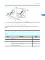
Seal Check and Removal
2
• You must check the box seals to make sure that they were not removed after the items were sealed in
the box at the factory before you do the installation.
1. Check the box seals [A] on each corner of the box.
• Make sure that a tape is attached to each corner.
• The surfaces of the tapes must be blank. If you see “VOID” on the tapes, do not install the
components in the box.
2. If the surfaces of the tapes do not show “VOID”, remove them from the corners of the box.
3. You can see the “VOID” marks [B] when you remove each seal. In this condition, they cannot be
attached to the box again.
Installation Procedure
85
2. Installation
1. Turn the SD-card label to face [A] the rear of the machine. Then push it slowly into slot 1 until you
hear a click.
2. Turn on the main power switch, and then enter the SP mode.
3. Select SP5878-002, and then press "Execute" on the LCD.
4. Exit the SP mode after "Completed" is displayed on the LCD.
2
5. Turn off the main power switch.
6. Remove the SD card from slot 1.
Recovery from a Device Problem
Restoring the Encryption key
When replacing the controller board for a model in which the HDD encryption unit has been installed,
updating the encryption key is required.
1. Prepare an SD card which is initialized.
2. Make the "restore_key" folder in the SD card.
3. Make an "nvram_key.txt" file in the "restore_key" folder in the SD card.
4. Ask an administrator to input the encryption key (this has been printed out earlier by the user) into the
"nvram_key.txt" file.
5. Remove only the HDD unit (
86
HDD).
Controller Options
6. Turn on the main power switch.
7. Confirm that the prompt on the LCD tells you to install the SD card (storing the encryption key) in the
machine.
8. Turn off the main power switch.
9. Insert the SD card that contains the encryption key into slot 1.
10. Turn on the main power switch, and the machine automatically restores the encryption key in the flash
memory on the controller board.
2
11. Turn off the main power switch after the machine has returned to normal status.
12. Remove the SD card from slot 1.
13. Reinstall the HDD unit.
Clearing the NVRAM
When replacing the controller board for a model in which the HDD encryption unit has been installed and
a customer has lost the encryption key, clearing the NVRAM is required to recover the HDD encryption
unit.
1. Prepare an SD card which is initialized.
2. Make the "restore_key" folder in the SD card.
3. Make an "nvram_key.txt" file in the "restore_key" folder in the SD card.
4. Input "nvclear" into the "nvram_key.txt" file.
5. Turn on the main power switch.
6. Confirm that the prompt on the LCD tells you to install the SD card (storing the encryption key) in the
machine.
7. Turn off the main power switch.
8. Insert the SD card that contains "nvclear" into slot 1.
9. Turn on the main power switch, and the machine automatically restores the encryption key in the flash
memory on the controller board.
10. Turn off the main power switch after the machine has returned to normal status.
11. Remove the SD card from slot 1.
12. Turn on the main power switch.
13. Initialize the NVRAM (SP5801-001) and HDD unit (SP5832-001) with SP mode.
14. The user must enable the HDD encryption unit with a user tool.
87
2. Installation
2
88
3. Preventive Maintenance
Maintenance Tables
See "Appendices" for the following information:
• PM tables
3
89
3. Preventive Maintenance
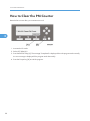
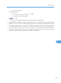
How to Clear the PM Counter
Reset the PM counter after your maintenance work.
3
1. Activate the SP mode.
2. Select SP7-804-001.
3. Press the EXECUTE key [A]. The message "Completed" is displayed when the program ends normally.
An error message is displayed if the program ends abnormally.
4. Press the Escape key [B] to end the program.
90
4. Replacement and Adjustment
Precautions
General
• Turn off the main power switch and unplug the machine before starting replacement.
Before turning off the main power switch, check that no mechanical component is operating. Mechanical
components may stop out of their home positions if you turn off the main power switch while they are
operating. The component may be damaged if you try to remove it when it is not in the home position.
4
Lithium Batteries
• Incorrect replacement of lithium battery(s) on the controller or on the fax unit poses risk of explosion.
Replace only with the same type or with an equivalent type recommended by the manufacturer.
Discard used batteries in accordance with the manufacturer’s instructions.
Halogen-free Cable
• Use extreme caution while handling cables.
To comply with local regulations, halogen-free cables are used in this machine. Halogen-free cables are
environment-friendly, but no stronger than conventional cables. These cables may be damaged in any of
the following cases:
• The cable is caught between hard objects such as brackets, screws, PCBs, and exterior covers.
• The cable is rubbed on a hard object such as brackets, screws, PCBs, and exterior covers.
• The cable is scratched with a hard object such as brackets, screws, PCBs, exterior covers,
screwdrivers, and fingernails.
91
4. Replacement and Adjustment
Special Tools and Lubricants
Part Number
4
92
Description
Q’ty
A1849501
Optics Adjustment Tools (2 pcs/set)
1 set
A2929500
Test Chart – S5S (10 pcs/set)
1 set
VSSM9000
Digital Multimeter – Fluke 87
1
N8036701
Flash Memory Card (4MB)
1
N8031000
Case for Flash Memory Card
1
A2579300
Grease Barrierta – S552R
1
52039502
Silicon Grease 501
1
Exterior Covers and Operation Panel
Exterior Covers and Operation Panel
Rear Cover
4
1. Open the right door [A].
2. Interface cover [B] ( x 1)
3. Open the right door [A].
4. Rear cover [C] ( x 5)
Copy Tray
• Make sure that the cables under the copy tray are in place before reassembling the copier. If these
cables are caught between the copy tray and the inner cover, they may be severely damaged.
93
4. Replacement and Adjustment
4
1. Open the front door [A].
2. Copy tray [B] ( x1)
Reassembling:
There are several cables under the front end of the copy tray. To set these cables in place, gently pull these
cables to the left-hand side (toward the PSU) and hold them there as you attach the copy tray.
Scale Plate (D067 only)
1. Scale plate [A] ( x 2)
94
Exterior Covers and Operation Panel
Operation Panel and Upper Covers
4
1. Remove the ARDF.
• For D072: Remove the ARDF, if it has been installed.
2. Rear cover (
"Rear Cover")
3. Slide the upper left cover [A] to the rear.
4. Rear scale [B] ( x 3)
5. Slide the upper right cover [C] to the rear.
6. Front left cover [D] ( x 2)
7. Operation panel [E] ( x 4,
x 1)
8. Front right cover [F]
95
4. Replacement and Adjustment
Right Door
4
1. Open the right door [A].
2. Release the strap [B].
3. Right door (
Bypass Tray
96
x 1)
Exterior Covers and Operation Panel
1. Press the stopper rails [A] inward.
Platen Cover Sensor
4
1. Rear cover (
"Rear Cover")
2. Rear scale (
"Operation Panel and Upper Covers")
3. Platen cover sensor [A] (
x 1, hook)
97
4. Replacement and Adjustment
Scanner Unit
To clean the mirrors and lenses, use a blower brush or wet cotton.
Exposure Glass
To clean the exposure glass, use alcohol or glass cleaner.
4
Non-ARDF machines
1. Rear cover (
"Rear Cover")
2. Scale plate (
"Operation Panel and Upper Covers")
3. Exposure glass [A]
ARDF-equipped machines
1. Rear cover (
"Rear Cover")
2. Rear scale, upper right cover (
"Operation Panel and Upper Covers")
3. Exposure glass [A]
Reassembling
Make sure that the marking on the glass is at the rear left corner, and that the left edge of the glass is aligned
flush against the support ridge [B] on the frame.
Adjustment
When replacing the white plate, perform the "Scan Auto Adjustment" (
98
SP4-428-001).
Scanner Unit
Lens Block
• Do not disassemble the lens block. The lens block is precision adjusted before shipment.
• Do not touch the screws on the CCD. The CCD is precision adjusted before shipment.
4
1. Exposure glass (
"Exposure Glass")
2. Front left cover, operation panel (
"Operation Panel and Upper Covers")
3. Release the cable from the four clamps [A].
4. Lens block [B] ( x 4, 1 flat cable)
• Do not loosen the paint-locked screws holding the lens unit in place.
• After installing a new lens block, carry out copy adjustments (
"Adjusting Copy Image Area").
Exposure Lamp, Lamp Stabilizer Board
Do not fold the exposure cable on the exposure lamp.
99
4. Replacement and Adjustment
4
1. Exposure glass (
"Exposure Glass")
2. Front left cover, operation panel (
"Operation Panel and Upper Covers")
3. Slide the first scanner to a position where the lamp and scanner are clear of the metal lids.
4. Disconnect the lamp connector [A].
5. Remove either or both of the following:
• Exposure lamp [B] ( x 1)
• Lamp stabilizer board [C] ( x 2, 1 flat cable)
Scanner Motor
1. Rear cover (
"Rear Cover")
2. Rear scale, upper right cover (
100
"Operation Panel and Upper Covers")
Scanner Unit
4
3. Remove the right platen stay holder [A] ( x 3).
4. Scanner motor [B] ( x 3, 1 spring, 3 screw holders,
x 1)
Reinstalling
When reinstalling, fasten the screws loosely, set the spring in place, and tighten up the screws.
101
4. Replacement and Adjustment
Scanner HP Sensor
4
1. Rear cover (
"Rear Cover")
2. Front left cover (
3. Scale plate (
"Operation Panel and Upper Covers")
"Scale Plate")
4. Scanner HP sensor [A] (
x 1, hook)
• Move the first scanner from the home position if you have difficulty removing the sensor.
Scanner Alignment Adjustment
1. Rear cover (
"Rear Cover")
2. Rear scale, upper right cover, front left cover, operation panel (
Covers")
3. Exposure glass (
"Operation Panel and Upper
”Exposure Glass")
4. Loosen the 2 screws holding the 1st and 2nd scanner belts in place.
102
Scanner Unit
5. Slide the 1st and 2nd scanners so that all four of the following are roughly aligned on both the front
and back sides:
4
• The hole in the copier's lid
• The hole in the 1st scanner
• The right corner hole in the 2nd scanner
• The hole at the base of the scanner
6. Insert the two optics adjustment tools [A], and adjust the scanners as necessary so that the tools go
through all four holes.
7. Tighten the two screws that you loosened at step 2 above, so that the belts are firmly clamped into
place.
8. Remove the adjustment tools.
103
4. Replacement and Adjustment
Fusing
Fusing Unit
• Before handling the fusing unit, make sure that the unit is cool enough. The fusing unit can be very hot.
4
1. Copy tray (
"Copy Tray")
2. Open the right door.
3. Connector cover [A] ( x 1)
• When reinstalling, attach the ground wire.
4. Fusing unit [B] ( x 2,
104
x 4)
Fusing
Exit Sensor
4
1. Fusing unit (
"Fusing Unit")
2. Exit sensor [A] (
x 1)
Hot Roller Stripper Pawls
• Take care not to damage the hot roller stripper pawls and the tension springs.
105
4. Replacement and Adjustment
4
1. Fusing unit (
"Fusing Unit")
2. Separate the fusing unit into two sections: the hot roller section [A] and the pressure roller section [B]
( x 2).
After removing the screws, lower the pressure roller section about halfway and then slide it toward
the front side to detach it.
3. Support rollers [C]
4. Hot roller stripper pawls [D]
• Remove the spacer [E] ( x 1) if you are removing the hot roller assembly (
Fusing Lamp").
Hot Roller and Fusing Lamp
• Do not touch the fusing lamp and rollers with your bare hands.
106
"Hot Roller &
Fusing
4
1. Hot roller stripper pawls and spacers (
"Hot Roller Stripper Pawls")
2. Hot roller assembly [A] ( x 2)
3. Fusing lamp [B]
• When reassembling, check that the direction of the fusing lamp is correct.
4. Hot roller [C] (2 C-rings, 1 spacer, 1 gear, 2 bushings, 1 cover [D])
Reassembling
Be sure that:
• The fusing lamp is positioned correctly.
• The fusing lamp does not touch the internal part of the hot roller.
107
4. Replacement and Adjustment
Thermoswitches and Thermistor
4
1. Hot roller assembly (
"Hot Roller & Fusing Lamp")
2. Thermoswitches ( x 2 for each)
3. Thermistor ( x 1)
Reassembling
Make sure of the following:
• That the thermistor is in contact with the hot roller.
• That the hot roller turns smoothly.
• Do not recycle a thermoswitch that is already opened. Safety is not guaranteed if you do this.
108
Fusing
Pressure Roller
4
1. Separate the fusing unit into two sections (
"Hot Roller Stripper Pawls").
2. Fusing entrance guide [A]
3. Two springs [B][C]
4. Two pressure arms [D][E]
5. Bushing [F]
6. Pressure roller [G]
109
4. Replacement and Adjustment
Checking the NIP band
You can check the nip band to see if the fusing unit is in a good condition–especially, if the hot roller and
pressure roller are correctly installed.
1. Activate the SP mode.
2. Select SP1-109-001.
3. Specify "1."
4. Press the OK key.
5. Press the
4
key. The copy mode is activated.
6. Place an OHP sheet on the by-pass tray.
7. Press the key. The copier feeds the OHP sheet, and stops it between the hot roller and the pressure
roller for about 20 seconds.
8. Wait until the OHP sheet is output.
9. Press the
key.
10. Make sure SP1-109-001 is selected.
11. Specify "0".
12. Press the OK key.
13. Quit the SP mode.
You see an opaque stripe on the OHP sheet. This is the trace of the nip band. The normal nip band is
symmetrical on the OHP sheet. Both ends are slightly thicker than the center.
• There are no specifications or standards for the nip band of this copier.
110
PCU and Quenching Lamp
PCU and Quenching Lamp
When handling the photo conductor unit (PCU), use caution:
• Do not touch the OPC drum with your bare hands. When the OPC drum is unclean, clean it with dry
cloth, or clean it with wet cotton and wipe it with dry cloth.
• Do not use alcohol or any other chemicals to clean the OPC drum. These substances damage the
OPC-drum surface.
• Keep PCUs in a cool, dry place.
• Do not expose the OPC to any corrosive gas such as ammonia.
• Do not shake a used PCU. Remaining toner and developer may spill out.
• Dispose of used PCUs in accordance with local regulations.
4
PCU
1. Open the right door.
• The PCU may become stuck if you try to remove it while the front door is closed.
2. Open the front door.
3. Remove the toner bottle holder.
• Clean all spilled toner off the toner bottle area and the inside of the front door.
4. Pull out the PCU [A] (
x 1).
5. When having installed a new PCU, remove the Styrofoam and tags (
the chapter "Installation").
"Installation Procedure" in
Initialization
111
4. Replacement and Adjustment
After you turn on the main power switch, the copier automatically initializes the new PCU. When the copier
is executing initialization, it is important that you:
• Do not turn off the main power switch.
• Do not open or remove exterior covers.
Quenching Lamp
4
1. PCU (
"PCU")
2. Quenching lamp [A] (
112
x 1)
Exhaust Fan and Main Motor
Exhaust Fan and Main Motor
Exhaust Fan
4
1. Rear cover (
"Rear Cover")
2. Exhaust fan [A] ( x 2,
x 1)
Reassembling
Make sure that the arrow [B] on the frame points to the rear side. The arrow indicates the direction of
airflow.
113
4. Replacement and Adjustment
Main Motor
4
1. Rear cover (
"Rear Cover")
2. High-voltage power supply board (
"High-Voltage Power Supply Board")
3. Ground plate [A] ( x 1)
4. Main motor with the gear cover [B] (
x 1,
5. All gears [C]
6. Main motor [D] ( x 4)
Reassembling
Attach the main motor before attaching the gears.
114
x 7,
x 2, 2 bushings)
Paper Feed
Paper Feed
Paper Feed Roller and Friction Pad
When handling the paper tray or the paper feed roller, use caution:
• Do not touch the surface of paper feed rollers.
• To avoid paper jams, correctly set the side and end fences in the paper tray.
4
1. Paper tray
2. Shaft [A] (
x 1)
3. Remove either or both of the following:
• Paper feed roller [B]
• Friction pad [C]
115
4. Replacement and Adjustment
Paper End Sensor
4
1. Paper tray
2. Open the right door.
3. PCU (
”PCU")
4. Paper end sensor [A] (
x 1)
Registration Sensor
1. Paper tray
2. Open the right door.
3. Open the paper guide [A].
• Remove the paper guide (Clip x 1) if you have difficulty removing the registration sensor.
116
Paper Feed
4. Registration sensor feeler [B]
5. Registration sensor [C] (
x 1)
• Disconnect the connector (CN127 [D]) if you have difficulty removing the registration sensor.
Bypass Paper End Sensor
4
1. Right door (
"Right Door")
2. Sensor compartment [A]
3. Bypass paper end sensor [B] (
x 1)
117
4. Replacement and Adjustment
Bypass Feed Roller
4
1. Right door (
"Right Door")
2. Turn the feed roller housing upside down [A] ( x 2).
3. Feed roller shaft [B] (2 snap pawls [C], 1 spacer [D])
4. Bypass feed roller [E]
118
Paper Feed
Bypass Feed Clutch and Friction Pad
4
1. Rear cover (
"Rear Cover")
2. Right door (
"Right Door")
3. Disconnect the bypass feed clutch connector [A] (CN93).
4. Bypass feed roller housing [B] ( x 2)
5. Bypass feed clutch [C] (
x 1)
6. Bypass friction pad [D]
119
4. Replacement and Adjustment
Paper Feed and Registration Clutches
4
1. Paper tray
2. High-voltage power supply board (
"High-Voltage Power Supply Board")
3. Ground plate [A] ( x 1)
4. Gear cover [B] (
x 1,
x 7,
x 2, 2 bushings)
• Do not remove the main motor from the gear cover.
120
Paper Feed
4
5. Ground plate [C] ( x 1)
6. Slowly push the clutch holder [D] and remove the registration clutch [E] (
x 1,
x 1).
7. Paper feed clutch [F]
121
4. Replacement and Adjustment
Image Transfer
Transfer Roller
• Do not touch the transfer roller with your bare hands.
• Do not scratch the transfer roller. The transfer roller is easily damaged.
4
1. Right door (
"Right Door")
2. Raise the levers [A],[B] at the ends of the image transfer roller.
3. Release the image transfer roller [C].
Reassembling
Make sure that the springs [D] are in the original positions.
122
Image Transfer
ID Sensor and Duplex Roller
4
1. Right door (
"Right Door")
2. Lower guide [A]
3. Idle roller holders [B][C]
4. Idle roller [D]
5. Roller guide [E]
6. Transfer unit [F]
7. One-way gear [G] (
8. Duplex roller [H] (
x 1)
x 1, 3 bushings)
123
4. Replacement and Adjustment
4
9. ID sensor [I] (
x 1)
Discharge plate
1. Right door (
"Right Door")
2. Discharge plate [A]
124
BICU and Controller Board
BICU and Controller Board
• Turn off the main power switch and unplug the machine before starting replacement.
• Before turning off the main power switch, check that no mechanical component is operating.
Mechanical components may stop out of their home positions if you turn off the main power switch
while they are operating. The component may be damaged if you try to remove it when it is not in the
home position.
For basic models (D067/D072):
The table lists the components and necessary maintenance work
Model
Basic
BICU
NVRAM
Installed
Controller Box
None
4
Controller
NVRAM
None
Maintenance Work
Save the data from the NVRAM to a
memory card before replacing the
NVRAM.
BICU
Preparation
• Before replacing the NVRAM, be sure to save the NVRAM data.
• Saving from the BICU NVRAM to an SD card ( "NVRAM Data Upload/Download
(SP5-824/825)" in the "System Service Mode" of the appendices of the this manual.)
125
4. Replacement and Adjustment
Procedure
4
1. Rear cover (
"Rear Cover")
2. Scanner upper left cover (
"Operation Panel and Upper Covers”)
3. Bracket at the left-rear frame (basic models [D067/D072]:
[D068/D069]: x 6,
x 1)
4. Ground plate [B] ( x 2)
126
x 2) or controller box [A] (F/SPF models
BICU and Controller Board
5. BICU [C] (all
, 2 flat cables,
x 6)
• When replacing the BICU, remove the NVRAM [D] from the board. Install the NVRAM to the
new board.
6. After replacing the NVRAM, copy the saved data to the NVRAM.
• From an SD card to the NVRAM ( "NVRAM Data Upload/Download (SP5-824/825)" in
the "System Service Mode" of the appendices of the this manual.)
Controller Board (F/SPF models: D068/D069)
4
Preparation:
• Before replacing the controller board, be sure to print out SMC or save the NVRAM data.
• Saving from the Controller NVRAM to an SD card ( "NVRAM Data Upload/Download
(SP5-824/825)" in the "System Service Mode" of the appendices of the this manual.)
Procedure
1. Rear cover (
"Rear Cover")
2. Scanner upper left cover (* "Operation Panel and Upper Covers”)
3. FCU (
"FCU")
127
4. Replacement and Adjustment
4
4. Remove the printer/scanner SD card.
5. Remove I/F cover [A] (or I/F options if they have been installed) ( x 2).
6. Remove the bracket [B] ( x 1).
7. Remove the USB cap [C].
128
BICU and Controller Board
4
8. Remove the relay connector [A].
9. Remove the ground plate [B] ( x 1).
10. Remove the controller board with the rails [C] ( x 6).
129
4. Replacement and Adjustment
4
11. Release the hooks, and then pull out the rails [A].
12. Remove the DIMM [B] if it has been installed.
• When replacing the controller board, remove the NVRAMs from the board. Install the NVRAMs
to the new board.
130
BICU and Controller Board
When replacing the NVRAM on the controller board
4
1. When you replace the NVRAM [A], make sure that the NVRAM is correctly installed.
2. The mark [B] on the NVRAM should be directed to the down side (seem from the back side of the
machine).
3. Reassemble the machine.
4. Copy the old NVRAM data to the new NVRAM with SP5-825 or input the SMC data in the machine.
(For details, refer to the "NVRAM Data Upload/Download [SP5-824/825]" in the "System Service
Mode" of the appendices of the this manual)
When Installing the Printer/Scanner Unit (D468)
Refer to procedure “Controller Board (F/SPF models: D068/D069)” in this section, and carry out the
steps (without step 3).
131
4. Replacement and Adjustment
Other Replacements
Duplex Motor
4
1. Rear cover (
"Rear Cover")
2. Duplex motor [A] ( x 1,
132
x 2)
Other Replacements
High-Voltage Power Supply Board
4
1. Rear cover (
"Rear Cover")
2. High-voltage power supply board [A] (all
,
x 4)
• Remove the insulating sheet [B] if you are going to remove the contact-release solenoid (
"Contact-Release Solenoid") or the gear cover ( "Paper Feed and Registration Clutches").
133
4. Replacement and Adjustment
PSU
4
1. Open the front door.
2. Copy tray (
"Copy Tray")
3. PSU assembly [A] (
4. PSU [B] (
134
x 4,
x 4,
x 6)
x 8)
Other Replacements
Contact-Release Solenoid
4
1. Rear cover (
"Rear Cover")
2. High-voltage power supply board (
3. Contact-release solenoid [A] (1 spring,
"High-Voltage Power Supply Board")
x 1)
Toner Supply Clutch
1. Toner bottle holder
135
4. Replacement and Adjustment
2. Copy tray (
3. Rear cover (
"Copy Tray")
"Rear Cover")
4. Disconnect the connector on C19 on the BICU.
5. Push the clutch coupler [A] to the rear side, and remove the clip ring [B] from the back of the copier.
6. Coupler and spring [C]
7. Lift the toner supply clutch [D] and remove it.
• When removing, note how the wire goes through a clamp, and also note where it passes through
the rear of the machine.
4
FCU (For D068/D069)
Lithium Batteries
• Incorrect replacement of lithium battery(s) on the controller or on the fax unit poses risk of explosion.
Replace only with the same type or with an equivalent type recommended by the manufacturer.
Discard used batteries in accordance with the manufacturer’s instructions.
Procedure
1. Open the right door [A].
2. Rear cover [B] ( x 5).
3. Scanner upper left cover [C]
136
Other Replacements
4
4. Controller box cover [A] ( x 13)
5. FCU [A] ( x 4, x 1)
6. When you replace the FCU board, remove the MBU board from the old FCU board and install it on
the new FCU board.
7. Set the correct date and time with the User Tools: User Tools> System Settings> Timer Setting> Set
Date/Time
137
4. Replacement and Adjustment
• Do not turn off the battery switch (SW1).
• Do SP6-101 in the "Fax SP" to print the system parameters, and check the settings.
4
138
Laser Unit
Laser Unit
• Turn off the main power switch and unplug the copier before starting replacement. The laser beam
can damage your eyes severely.
• Do not touch the screws on the LD board on the LD unit. Do not try to adjust any part of the LD unit.
The LD unit is precision adjusted before shipment.
• Do not touch the polygon mirror, shield glass, or lenses with your bare hands.
Location of the Caution Decal
4
Laser Unit
1. PSU assembly (
"PSU")
2. Toner bottle holder
3. Laser unit [A] ( x 3,
x 2)
Reassembling
139
4. Replacement and Adjustment
4
Make sure that the cable [B] passes under the unit.
LD Unit and Polygon Mirror Motor
1. Laser unit (
"Laser Unit")
2. Laser unit cover [A] ( x 2, 1 grounding plate)
3. LD unit [B] ( x 2)
4. Polygon mirror motor [C] ( x 4)
Reassembling
Check that the polygon mirror and toroidal lens are clean. Dust or other foreign substances may interfere
with the operation of the LD unit.
140
ARDF
ARDF
ARDF
1. Rear cover (
"Rear Cover")
4
2. Remove the DF interface cables [A] (
x 2, hook x 2).
3. Remove the ground cable [B] ( x 1).
4. Remove the stud screw [C].
5. Remove the ARDF [D].
141
4. Replacement and Adjustment
DF Rear Cover
4
1. Open the ARDF [A].
2. Release the three hooks
3. Open the DF left cover [B].
4. Open the original tray [C].
5. DF rear cover [D] ( x 1, hook x 4)
Original Feed Unit
1. Open the DF left cover.
142
ARDF
2. Original feed unit [A] (c x 1)
4
Separation Roller
1. Open the DF left cover.
2. Original feed unit (
"Original Feed Unit")
3. Separation roller cover [A] (hook x 2)
4. Separation roller stopper [B] (hook)
5. Separation roller [C]
DF Drive Board
1. DF rear cover (
"DF Rear Cover")
143
4. Replacement and Adjustment
4
2. DF drive board [A] ( x 2,
x 4, ground cable x 1)
Original Set and DF Inverter Sensor
1. Open the DF left cover.
2. Original feed unit (
3. DF feed clutch (
"Original Feed Unit")
"DF Feed Clutch")
4. Original feed-in guide plate [A] ( x 2).
144
5. Original set sensor [B] (
x 1, hook)
6. DF inverter sensor [C] (
x 1, hook)
ARDF
DF Registration and DF Exit Sensor
1. Open the DF left cover.
2. Original feed unit (
3. DF feed clutch (
"Original Feed Unit")
"DF Feed Clutch")
4. Original feed-in guide plate (
5. DF feed motor (
"Original Set and Inverter Sensor")
"DF Feed Motor")
6. DF transport motor (
"DF Transport Motor")
4
7. DF transport roller [A] (
x 2, gear x 2, bushing x 2)
8. DF separation roller unit [B] (
x 2, gear x 1, bushing x 2)
9. Inverter upper guide plate [C] ( x 4,
x 3,
x 4)
145
4. Replacement and Adjustment
4
10. Inverter lower guide plate [D] (hook x 2)
11. DF registration sensor [E] (
12. DF exit sensor [F] (
x 1, hook)
x 1, hook)
DF Registration Sensor Reflector
Clean the SD registration sensor reflector [A] as necessary.
DF Feed Motor
1. DF rear cover (
146
"DF Rear Cover")
ARDF
4
2. Inner cover [A] ( x 1)
3. DF feed motor with bracket [B] ( x 2,
x 4,
x 3, timing belt)
4. DF feed motor [C] ( x 2)
DF Transport Motor
1. DF rear cover (
"DF Rear Cover")
2. DF feed motor (
"DF Feed Motor")
3. DF transport motor with bracket [A] ( x 2, spring x 1, timing belt)
147
4. Replacement and Adjustment
4. DF transport motor [B] ( x 2)
DF Feed Clutch
4
1. Open the DF left cover.
2. DF front cover [A] ( x 1)
148
3. Bracket [B] ( x 1,
x 1)
4. DF feed clutch [C] (
x 1)
Adjusting Copy Image Area
Adjusting Copy Image Area
Adjust the copy image area under any of the following conditions:
1. After clearing engine data (SP5-801-002 or SP5-998-001).
2. After replacing any of the following components:
• First scanner or second scanner
• Lens block
• Scanner motor
• Polygon mirror motor
• Paper tray
4
Printing
Make sure that the paper is correctly loaded in each paper tray before starting the adjustment procedures
in this section.
Adjusting Registration
Use the Trimming Area Pattern (SP5-902-001 > 10) for this adjustment.
1. Print out the test pattern with the paper fed from the regular paper tray.
2. Print out the test pattern with the paper fed from the by-pass tray.
3. Print out the test pattern by selecting duplex printing.
4. Measure the distance between the leading edge of the image area and the leading edge of the paper
[A].
• The diagram shows the paper on the copy tray. Note that the paper is output with the face down.
149
4. Replacement and Adjustment
SP
Specification
SP1-001-001 (All Trays)
0 ± 2 mm
SP1-001-002 (By-pass)
0 ± 2 mm
SP1-001-003 (Duplex)
0 ± 4 mm
5. Adjust the leading edge registration (SP1-001).
6. Measure the distance between the side edge of the image area and the side edge of the paper [B].
SP
4
Specification
SP1-002-001 (1st tray)
0 ± 2 mm
SP1-002-002 (2nd tray)
0 ± 2 mm
SP1-002-005 (By-pass)
0 ± 4 mm
SP1-002-006 (Duplex)
0 ± 4 mm
7. Adjust the side-to-side registration (SP1-002).
8. Specify "0" (zero) in SP5-902-001 after finishing the adjustment procedure.
Adjusting Blank Margin
Use the Trimming Area Pattern (SP5-902-001 > 10) for this adjustment.
1. Print out the test pattern.
2. Measure the distance between the four edges of the image area and the four edges of the paper [A]
[B][C][D].
• The diagram shows the paper on the copy tray. Note that the paper is output with the face down.
150
Adjusting Copy Image Area
3. Adjust the blank margin (SP2-101).
SP
Specification
SP2-101-001 (Leading Edge) [A]
2 ± 1.5 mm
SP2-101-002 (Trailing Edge) [B]
2 +2.5/-1.5 mm
2 ± 1.5 mm
SP2-101-003 (Left Side) [C]
SP2-101-004 (Right Side) [D]
2 +2.5/-1.5 mm
• The "Left Side" and "Right Side" comes to your left-hand side and right-hand side respectively
when you view the copied image with the leading edge upwards.
4
4. Specify "0" (zero) in SP5-902-001 after finishing the adjustment procedure.
Adjusting Main-Scan Magnification
Use the Grid Pattern (Single Dot) (SP5-902-001 > 5) for this adjustment.
SP
SP2-998-001 (Main Mag-print)
Specification
100 ± 1%
1. Print out the test pattern.
2. Measure the sides of squares. Each side should be 2.7-mm long.)
3. Adjust the main-scan magnification (SP2-998-001: Main Mag-print).
4. Specify "0" (zero) in SP5-902-001 after finishing the adjustment procedure.
Scanning
Preparation:
• Before adjusting scanning, adjust printing (
"Printing" in this section).
• To adjust scanning, use the A4 test chart.
Adjusting Registration
1. Place the test chart on the exposure glass. Make sure that the test chart is aligned with the rear and
left scales on the exposure glass.
151
4. Replacement and Adjustment
2. Make a copy.
4
3. Measure the distance between the leading edge of the image area and the leading edge of the paper
[A].
• The diagram shows the paper on the copy tray. Note that the paper is output with the face down.
4. Adjust the leading-edge scan registration. (SP4-010-001).
SP
Specification
SP4-010-001 (LE Scan Regist)
0 ± 2 mm
5. Measure the distance between the side edge of the image area and the side edge of the paper [B].
6. Adjust the side-to-side registration (SP4-011-001).
152
SP
Specification
SP4-011-001 (S-to-S Scan Regist)
0 ± 2 mm
Adjusting Copy Image Area
Adjusting Magnification
4
1. Place the test chart on the exposure glass. Make sure the test chart is aligned with the rear and left
scales on the exposure glass.
2. Make a copy.
3. Compare the copy with the original.
4. Adjust the main-scan and sub-scan magnifications. The original image [A] is magnified in the mainscan direction [B] or in the sub-scan direction [C] when you specify a larger value.
• The diagrams show the paper on the copy tray. Note that the paper is output with the face down.
SP
Specification
SP4-009-001 (Main Scan Mag)
± 1.0%
SP4-008-001 (Sub Scan Mag)
± 1.0%
Scan Auto Adjustment
This procedure adjusts the standard white density level. Adjust the standard white density after any of the
following maintenance work:
• Replacing the standard white plate
• Replacing the BICU
153
4. Replacement and Adjustment
• Replacing the lens block
• Executing the memory clear (SP5-801-002 [basic model], SP5-998-001 [other models]).
1. Place 10 sheets of new A4 paper on the exposure glass.
2. Close the platen cover.
3. Activate the SP mode.
4. Select Copy SP4-428.
5. Specify "1" and press the OK key. The copier automatically adjusts the standard white density.
DF Image Adjustment
4
• Perform the adjustment procedure in this section only when the ARDF is installed on the copier.
1. Make a temporary test chart as shown in the above diagram. Use the “A4/8.5 x 11" paper to make
it.
2. Place the temporary test chart on the ARDF.
3. Make a copy.
4. Measure the distance between the side edge of the image area and the side edge of the paper [A].
154
Adjusting Copy Image Area
(The diagram shows the paper on the copy tray. Note that the paper is output with the face down.)
5. Adjust the side-to-side registration (S to S/Front Regist: SP6-006-001, S to S/Rear Regist:
SP6-006-004). The image area moves to the rear side of the copier when you specify a larger value.
6. Measure the distance between the leading of the image area and the leading edge of the paper [B].
7. Adjust the leading edge registration (Leading Regist: SP6-006-002). The image area moves to the
right side of the copier when you specify a larger value.
8. Measure the distance between the trailing edge of the image area and the trailing edge of the paper
[C].
9. Adjust the erased area on the trailing edge (Trailing Erase: SP6-006-003).
10. Compare the copy with the original.
11. Adjust the sub-scan magnification (SP6-006-005). The specification is ±1.0%.
4
155
4. Replacement and Adjustment
4
156
5. Troubleshooting
Service Call Conditions
For "SC Table" information, see "Appendices".
5
157
5. Troubleshooting
Electrical Component Defects
See "Appendices" for the following information:
• Sensor/Switch
• Blown Fuse Conditions
(Power Supply Unit)
• BICU LED Display
5
158
Card Save Function
Card Save Function
Overview
Card Save:
• The Card Save function is used to save print jobs received by the printer on an SD card with no print
output. Card Save mode is toggled using printer Bit Switch #1 bit number 4. Card Save will remain
enabled until the SD card becomes full, or until all file names have been used.
• Captures are stored on the SD card in the folder /prt/cardsave. File names are assigned sequentially
from PRT00000.prn to PRT99999.prn. An additional file PRT.CTL will be created. This file contains a
list of all files created on the card by the card save function.
• Previously stored files on the SD card can be overwritten or left intact. Card Save SD has “Add” and
“New” menu items.
5
• Card Save (Add): Appends files to the SD Card. Does not overwrite existing files. If the card
becomes full or if all file names are used, an error will be displayed on the operation panel.
Subsequent jobs will not be stored.
• Card Save (New): Overwrites files in the card's /prt/cardsave directory.
Limitation:
• Card Save cannot be used with PJL Status Readback commands. PJL Status Readbacks will not work.
In addition they will cause the Card Save to fail.
Procedure
1. Turn the main power switch OFF.
2. Insert the SD card into the service slot of the controller board. Then turn the power ON.
• To determine which slot is the service slot, please see the service manual.
3. Enter SP mode.
4. Select “Printer SP”.
5. Select “Service Mode” and press “OK” button.
6. Select “1.001 Bit Switch” and press “OK” button.
159
5. Troubleshooting
7. Press “OK” button again.
5
8. Use the numeric key “4” to turn bit 4 ON. The result should look like: 00010000. By doing this Card
Save option will appear in “List/Test Print”.
9. Press the “Return” button several times to exit SP Mode.
10. Press the “
” button.
11. Use the arrow key and select “Printer Features”.
12. Use the arrow key and select “List/Test Print”.
13. Use the arrow key and select “Cardsave (ADD) or Cardsave (New).
160
Card Save Function
14. To enable the newly configured settings, select “switch” button and then press the “Return” button to
exit the “List/Test Print” menu.
15. Send a job to the printer.
16. As soon as the printer receives the data, it will be stored on the SD card automatically with no print
output. Nothing is displayed on the screen indicating that a Card Save operation was successful.
17. Press the “Return” button to exit Card Save mode.
18. Change the Bit Switch Settings back to the default 00000000.
19. Remove the SD card after main power switch is turned off.
5
Error Messages
Card Save error messages:
• Init error: A card save process (i.e. card detection, change to kernel mode) failed to initialize.
• Card not found: Card cannot be detected in the slot.
• No memory: Insufficient working memory to process the job.
• Write error: Failed to write to the card.
• Other error: An unknown error occurred.
If an error occurs, pressing “OK” will cause the device to discard the job and return to the ready state.
161
5. Troubleshooting
Fax Troubleshooting Guide (Only For D068/
D069)
See "Appendices" for the following information:
• Fax Error Codes
• IFAX Troubleshooting
• IP-Fax Troubleshooting
5
162
6. System Maintenance Reference
Service Program
• Do not let the user access the SP mode or the SSP mode. Only service representatives are allowed to
access these modes. The machine operation is NOT guaranteed after any person other than service
representatives accesses the SP mode.
SP Tables
See "Appendices" for the following information:
• Service Program Mode Tables for F/SFP models (D068/D069)
• Service Program Mode Tables for Basic models (D067/D072)
Using SP and SSP Modes
6
The following two modes are available:
• SP Mode (Service Program Mode): The SP Mode includes the programs that are necessary for
standard maintenance work.
• SSP Mode (Special SP Mode): The SSP Mode includes SP-Mode programs and some special
programs. You need some extra knowledge to use these special programs. For details, consult your
supervisor.
163
6. System Maintenance Reference
Starting SP Mode
1. Type the keys as follows:
ÔÔÔ
2. Press the key and hold it down until the SP-mode menu is displayed (about 3 seconds).
Selecting Programs
• When a blinking underscore (or several blinking underscores) is displayed, you can type a number
from the numeric keypad [D].
• When the sign “ /OK” [A] is displayed upper right corner, you can scroll through the menu by
pressing the left-arrow key [B] or the right-arrow key [C]. To select program, press the OK key [F].
Specifying Values
1. After locating a program, press the OK key. A blinking underscore (or several blinking underscores)
indicates which value you can change. The value in parentheses is the default value of the menu.
6
2. Type a necessary value from the numeric keypad. To switch between positive (plus) and negative
(minus) values, press the J key.
3. To validate the value, press the OK key. To cancel the value, press the escape key [E].
Activating Copy Mode
You can activate the copy mode while the SP mode is running. When you do so, the copier outputs images
or patterns that help you adjust the SP setting.
1. Press the key. The copy mode is activated.
2. Specify copy settings and press the key.
3. To return to the SP mode, press the key.
• You cannot end the SP mode while the copy mode is activated.
Quitting Programs/Ending (S) SP Mode
Press the key or the escape key to quit the program. You can end the SP mode by pressing one of
these keys several times.
Conventions used in the tables:
• Asterisk (*): The settings are saved in the NVRAM. Most of them return to the default values when you
execute SP5-801-002. CTL indicates that the data is contained in NVRAM on the controller board.
164
Service Program
• DFU: The program is for design/factory use only. Do not change the settings.
• Brackets ([ ]): The brackets enclose the setting rage, default value, and minimum step with unit
([Minimum to Maximum / Default / Step]).
6
165
6. System Maintenance Reference
Using SP Mode (F/SPF: D068/D069)
NVRAM Data Upload/Download
Uploading Content of NVRAM to an SD card
Follow this procedure to upload SP code settings from NVRAM to an SD card.
• This data should always be uploaded to an SD card before the NVRAM is replaced.
1. Before switching the machine off, execute SP 5990-1 (SMC Print). You will need a record of the
NVRAM settings if the upload fails.
2. Turn off the main power of the copier.
3. Remove the interface cover ( x 1).
6
4. Insert the SD card into the service slot 2, then turn on the main power of the copier.
5. Execute SP 5824-1 (NVRAM Data Upload) then press the “Execute” key.
• When uploading is finished, a file is coped to an NVRAM folder on the SD card. The file is saved
to the path and filename:
NVRAM\<serial number>.NV
Here is an example with Serial Number “B0700017”:
NVRAM\B0700017.NV
6. In order to prevent an error during the download, be sure to mark the SD card that holds the uploaded
(saved) data with the number of the machine from which the data was uploaded (saved).
• NVRAM data from more than one machine can be uploaded (saved) to the same SD card.
7. Turn off the main power, and then remove the SD card from the slot 2.
8. Reassemble the machine.
Downloading an SD Card to NVRAM
Follow this procedure to download (save) SP data from an SD card to the NVRAM in the machine.
• If the SD card with the NVRAM data is damaged, or if the connection between the controller and
BICU is defective, the NVRAM data download may fail.
• If the download fails, repeat the download procedure.
• If the second attempt fails, enter the NVRAM data manually using the SMC print you created before
uploading the NVRAM data. ( above procedure)
166
Using SP Mode (F/SPF: D068/D069)
1. Turn off the main power of the copier.
2. Remove the interface cover 2 ( x 1).
3. Insert the SD card with the NVRAM data into the service slot 2.
4. Turn on the main power of the copier.
5. Execute SP 5825-1 (NVRAM Data Download) and press the “Execute” key.
6. Turn off the main power of the copier, and then remove the SD card from the slot 2.
7. Reassemble the machine.
• In order for the NVRAM data to download successfully, the serial number of the file on the SD
card must match the serial number of the machine. If the serial numbers do not match, the
download will fail.
This procedure downloads (saves) the following data to the NVRAM:
• Total Count
• C/O, P/O Count
Firmware Update Procedure
6
This section illustrates how to update the firmware of the GW machine (the machine with the optional
controller box).
To update the firmware for the GW machine, you must have the new version of the firmware downloaded
onto an SD (Secure Digital) Card. The SD Card is inserted into the uppermost slot on the right side of the
controller box, viewed from the back of the machine.
Before You Begin…
An SD card is a precision device, so always observe the following precautions when handling SD cards:
• Always switch the machine off before inserting an SD card. Never insert the SD card into the slot with
the power on.
• When the power is switched on, never remove the SD card from the service slot.
• Never switch the machine off while the firmware is downloading from the SD card.
• Store SD cards in a safe location where they are not exposed high temperature, high humidity, or
exposure to direct sunlight.
• Always handle SD cards with care to avoid bending or scratching them. Never drop an SD card or
expose it to other shock or vibration.
Keep the following points in mind while you are using the firmware update software:
167
6. System Maintenance Reference
• “Upload” means to send data from the machine to the SD card, and “download” means to send data
from the SD card to the machine.
• To select an item on the LCD screen, press the appropriate key on the operation panel, or press the
appropriate number key on the 10-key pad of the operation panel.
• Before starting the firmware update procedure, always make sure that the machine is disconnected
from the network to prevent a print job for arriving while the firmware update is in progress.
Firmware Update Procedure
• Before beginning the following, first confirm which firmware version(s) are currently installed in the
machine with SP7-801-255.
-SD Card Preparation1. Format an SD card with, for example, SD Formatter v1.1.
2. Create a “romdata” folder on the card.
6
3. Create the following folders within the “romdata” folder: B121, B620, B622, B658, B681, B685
4. Download the firmware from the server and store the files in the folder with the corresponding model
code on the SD card.
Example:
File B1215540B should be stored in the “B121” folder, whereas files B6585902B, B6585903B,
and B6585905B should be stored in the “B658” folder.
-Firmware Update• Do not put multiple machine firmware programs on the same SD card. Copy the only model firmware
you want.
1. Turn off the main power switch.
2. If the machine is connected to a network, disconnect the network cable from the copier.
3. Remove the interface cover ( x 1)
4. With the label on the SD card facing the rear side of the machine, insert the SD card into the slot 2
on the controller box. Slowly push the SD card into the slot so it locks in place.
5. Make sure the SD card is locked in place.
(To remove the SD card, push it in to unlock the spring lock and then release it so it pops out of the
slot.)
6. Switch the main power switch on. After about 5 seconds, the LCD will display “Please wait…” Then,
about 60 seconds later, the LCD will display “Program UpDate Menu P.01” on the first line and the
name of the firmware on the second line (e.g. System/Copy).
168
Using SP Mode (F/SPF: D068/D069)
7. Press the "OK" key to select a module.
• To scroll through the menus, press the
or
keys [A].
6
• To view the firmware version, press the right key. "ROM" is the information on the current
firmware. "NEW" is the information on the firmware in the SD card.
• To return to the menu, press the
key.
• To select the module, press the OK key.
• To scroll through the module name, the serial number, and the version, press the key or key.
• If you wish to install the following firmware simultaneously, press the START key. The scroll keys
can be used to confirm that this firmware has been selected (highlighted with a dark background).
[Engine, FCU, Scanner, Printer, Printer Font, Security Module]
• Please note that the following firmware cannot be updated simultaneously. The update
procedure must be repeated for each individually.
• System/Copy, ServiceCardNetFile, ServiceCardNIB, ServiceCardFAX,
ServiceCardWebSystem.
169
6. System Maintenance Reference
• When you have selected a module, the text lines are highlighted, and the "Verify" key and the
"Update" key are displayed.
8. Select a module and press the "Update" key.
• Do NOT press the “Verify” key.
9. The firmware update program starts and the message "Loading" is displayed.
6
• The update will begin, and then will take a few minutes to complete. The LCD will initially display,
“Updating… ***---------“.
• When the update is completed, the LCD display will change to “Update done” or “Updated /
Power Off On”.
10. Check that the message "Update Done" is displayed.
-Confirmation1. Turn the main power switch off and on.
• The LCD will display “Please wait…” for about 60 seconds, after which it will return to the
“Program UpDate Menu” screen.
2. Repeat Steps 1-8 above until all firmware updates are complete.
3. Turn the main power switch off.
4. Remove the SD card from the lower slot on the controller by pushing on the card to release the spring
lock.
170
Using SP Mode (F/SPF: D068/D069)
If an error occurs, the error code is displayed. For a list of information on error codes, see the following
table.
Code
Cause
Necessary Action
E20
Physical address mapping
error
• Insert the SD card correctly.
E22
Decompression error
• Store correct data in the SD card.
• Use another SD card
• Update controller program.
E23
Update program error
E24
SD card access error
E31
Download data
inconsistency*
• Insert the SD card that was used when the previous update
procedure is interrupted.
E32
Download data
inconsistency*
• Insert the SD card that stores the correct data.
E33
Version data error
• Store the correct data in the SD card.
E34
Locale data error
• Store the correct data in the SD card.
E35
Machine model data error
• Store the correct data in the SD card.
E36
Module data error
• Store the correct data in the SD card.
E40
Engine program error**
E42
Operation panel program
error*
6
• Replace the controller.
• Insert the SD card correctly.
• Use another SD card.
• Store the correct data in the SD card.
• Replace BICU.
• Store the correct data in the SD card.
• Replace the operation panel board.
171
6. System Maintenance Reference
Code
Cause
Necessary Action
E44
Controller program error*
E50
Authentication error
• Store the correct data in the SD card.
• Replace the controller board.
• Store the correct data in the SD card.
*You need to reinstall the program.
If the firmware update program is interrupted (for example, by a power failure), keep the SD card inserted
and turn the mains switch off and on. The firmware update program restarts. If you do not do so, the message
"Reboot after Card insert" is displayed when you turn the main switch on.
Test Pattern Print (SP5-902-001)
Executing Test Pattern Printing
6
1. Specify the pattern number and press the OK key.
2. Press the copy start key. The copy mode is activated (
3. Specify copy settings and press the
4. To return to the SP mode, press the
key.
key.
Test Patterns
Test Patterns Using VCU
No.
172
Pattern
0
(No print)
1
Vertical Lines (Single Dot)
2
Horizontal Lines (Single Dot)
3
Vertical Lines (Double Dot)
4
Horizontal Lines (Double Dot)
5
Grid Pattern (Single Dot)
6
Grid Pattern (Double Dot)
7
Alternating Dot Pattern
"Using SP and SSP Modes” in this section).
Using SP Mode (F/SPF: D068/D069)
8
Isolated One Dot
9
Black Band (Horizontal)
10
Trimming Area
11
Argyle Pattern (Single Dot)
12
Grayscales (Horizontal)
13
Grayscales (Vertical)
14
Grayscales (Vertical/Horizontal)
15
Grayscales (Vertical/Horizontal Overlay)
16
Grayscales With White Lines (Horizontal)
17
Grayscales with White Lines (Vertical)
18
Grayscales with White Lines (Vertical/Horizontal)
6
Test Patterns Using IPU
No.
Pattern
30
Vertical Lines (Single Dot)
31
Horizontal Lines (Single Dot)
32
Vertical Lines (Double Dot)
33
Horizontal Lines (Double Dot)
34
Isolated Four Dots
35
Grid Pattern (Double Dot)
36
Black Band (Vertical, 1024 Dots)
37
Grayscales (Horizontal, 512 Dots)
38
Grayscales (Vertical, 256 Dots)
39
ID Patch
40
Cross
41
Argyle Pattern (128-Dot Pitch)
173
6. System Maintenance Reference
42
Square Gradation (64 Grades)
43
Square Gradation (256 Grades)
44
Grayscales (Horizontal, 32-Dot Width)
45
Grayscales (Vertical, 32-Dot Width)
47
A4 Gradation Patches 1 (128 Grades)
48
A4 Gradation Patches 2 (128 Grades)
49
Trimming Area (A4)
Test Patterns Using SBU
No.
6
Pattern
51
Grid Pattern (double dot)
52
Gray Scale 1 (256 grades)
53
Gray Scale 2 (256 grades)
Test Patterns Using PCI*1
No.
174
Pattern
61
S2M: Grid Pattern
62
S2M: Argyle Pattern
63
S2M: Argyle Pattern
64
S2M: Argyle Pattern + Image*2
65
S2M: Grid Pattern
66
S2M: Grid Pattern + Image
67
S2M: Argyle Pattern
68
S2M: Argyle Patten + Image
69
Engine: Grid Pattern
70
Engine: Argyle Pattern
Using SP Mode (F/SPF: D068/D069)
*1: The PCI is available to the models with the controller box.
*2: The original image on the exposure glass is printed behind the test pattern.
Memory Clear
GW Machine
The GW machine (the machine with the optional controller box) stores the engine data in the NVRAM on
the BICU, and stores the other data in the NVRAM on the optional controller. To distinguish between the
engine data and the other data, see SP5-801-003 through 015. This service program (SP5-801) handles
the controller data. Any data that is not handled by SP5-801 is the engine data. The data in the BICU
NVRAM (engine data) is cleared by SP5-998-001 while the data in the controller NVRAM (controller
data) is cleared by SP5-801-xxx (for exceptions, see "Exceptions" as described below).
Machine
Data
Engine data
GW
Controller data
NVRAM
BICU
Controller
Cleared by
Remarks
SP5-998-001
Any data other than controller data
SP5-801-xxx
SCS, IMH, MCS, Copier application,
Fax application, Printer application,
Scanner application, Web service/
network application, NCS, R-Fax,
DCS, UCS
6
Exceptions
SP5-998-001 clears most of the settings and counters stored in the NVRAM on the BICU (the values return
to their default values). However, the following settings are not cleared:
• SP5-807 (Area Selection)
• SP5-811-001 (Serial Num Input [Code Set])
• SP5-811-003 (Serial Num Input [ID2 Code Display])
• SP5-812-001 (Service TEL [Telephone])
• SP5-812-002 (Service TEL [Facsimile])
• SP5-907 (Plug & Play)
• SP7 (Data Log)
• SP8 (History)
Use SP5-998-001 after you have replaced the BICU NVRAM or when the BICU NVRAM data is corrupted.
When the program ends normally, the message "Completed" is displayed. When you have replaced the
175
6. System Maintenance Reference
controller NVRAM or when the controller NVRAM data is corrupted, use SP5-801-001. The message is
the same as the basic machine.
Memory Clear Procedure
1. Print out all SMC data lists (
"SMC Print").
2. Do SP5-998-001.
3. Press the OK key.
4. Select "Execute." The messages "Execute?" followed by "Cancel" and "Execute" are displayed.
5. Select "Execute."
6. When the program has ended normally, the message "Completed" is displayed. If the program has
ended abnormally, an error message is displayed.
7. Turn the main switch off and on.
8. Adjust the printer and scanner registration and magnification (* "Copy Adjustment" in the chapter
"Replacement and Adjustment").
6
9. Refer to the SMC lists, and enter any values that differ from the factory settings. Double-check the
values for SP4-901.
10. Adjust the standard white level (SP4-428).
11. Initialize the TD sensor (SP 2-214).
12. Check the copy quality and the paper path.
Machine No. Setting (SP5-811-001)
Specifying Characters
SP5-811-001 specifies the serial number. For the machine with the optional controller, you use the numeric
keypad and the optional operation panel.
GW Machine
You can use the numeric keypad to type numbers. In addition, you can use the operation panel to type
other characters. When you press the "ABC" key, the letter changes as follows: A Õ B Õ C. To input the
same letter two times, for example "AA," you press the "ABC" key, the "Space" key, and the "ABC" key.
To switch between uppercase letters and lowercase letters, press the "Shift" key.
176
Using SP Mode (F/SPF: D068/D069)
Serial Number and NVRAM
Serial numbers are stored in the NVRAM before shipment and are not cleared. You must specify a serial
number after you replace the NVRAM.
SMC Print (SP5-990)
SP5-990 outputs machine status lists.
1. Select SP5-990.
2. Select a menu:
• GW machine: 001 All (Data List), 002 SP (Mode Data List), 003 User Program, 004 Logging
Data, 005 Diagnostic Report, 006 Non-Default, 007 NIB Summary, 008 Net File Log, 021
Copier User Program, 022 Scanner SP, 023 Scanner User Program, 040 Parts Alarm Counter
Print, 064 Normal Count Print, 065 User Code Counter, 066 Key Operator Counter, 067
Contact List Print, 069 Heading1 print, 071 Heading3 print, 072 Group List Print, 128 ACC
Pattern, 129 User Color Pattern, or 160:ACC Pattern Scan
6
• The output given by the menu "Big Font" is suitable for faxing.
3. Press the "Execute" key.
• GW machine: The machine status list is output.
4. To return to the SP mode, press the
key.
ID Sensor Error Analysis (SP2-221)
The image quality may become very bad when the ID sensor does not operate properly. However, there
is no such SC code that indicates ID-sensor malfunction; instead, SP2-221 shows you some information
on the ID sensor. Check this information when the image quality is not very good.
The table lists the information shown with SP2-221 (ID Sensor Error Analysis).
SP
Error condition
SP2-221-1 Vsg
(VG in the display)
Vsg < 2.5V or
(Vsg – Vsp) < 1.00V
SP2-221-2 Vsp
(VP in the display)
Vsp > 2.5V or
(Vsg – Vsp) < 1.00V
Possible cause
Remarks
• ID sensor defective
• ID sensor dirty
-
• Drum not charged
• Toner density very low
• ID sensor pattern not
created
-
177
6. System Maintenance Reference
6
178
SP2-221-3 Power
(PW in the display)
Vsg < 3.5V
when maximum power
(979) is applied
SP2-221-4 Vsdp
No Error Conditions
SP2-221-5 Vt
Vt > 4.5V or
Vt < 0.2V
SP2-221-6 Vts
-
• ID sensor defective
• ID sensor dirty
• Drum not get charged
Power source
for the ID-sensor
light
-
• TD sensor defective
-
-
Using SP Mode (Basic: D067/D072)
Using SP Mode (Basic: D067/D072)
NVRAM Data Upload/Download (SP5-824/825)
• Make sure that you turn off the main power switch before inserting or removing a flash memory card.
Data in the memory may be corrupted if you insert or remove the memory card with the main power
switch on.
This section illustrates how to copy the data from the BICU NVRAM to a memory card ( "NVRAM Data
Upload/Download" writing onto open space on card) or from a memory card to the BICU NVRAM (
"NVRAM Data Upload/Download").
Overview
You can copy the data from the NVRAM to a flash memory card (NVRAM Upload) or from a flash memory
card to the NVRAM (NVRAM download).
SP5-824-1 (NVRAM Upload)
From the BICU to a flash memory card
SP5-825-1 (NVRAM Download)
From a flash memory card to the BICU
6
You should execute NVRAM Upload before replacing the NVRAM or before executing SP5-801-002
(Memory Clear > Engine). You can copy back the data from the flash memory card to the NVRAM as
necessary.
NVRAM Upload (SP5-824-001)
1. Turn off the main switch.
2. Remove the interface cover ( x 1).
3. Turn the face of the flash memory card to the rear of the copier, and insert it into the card slot 2.
4. Turn on the main power switch.
5. Activate the SP mode and select SP5-824-001.
6. The copier overwrites the data in the memory card with the data in the NVRAM. This takes about 20
seconds. If uploading fails, an error message appears. If an error message appears, retry the upload
procedure.
7. Turn off the main power switch.
8. Remove the memory card.
179
6. System Maintenance Reference
NVRAM Download (SP5-825-001)
SP5-825-001 copies the data from a flash memory card to the NVRAM. Most of the data in the NVRAM
is overwritten. The following data in the NVRAM remains unchanged (these are not overwritten):
• SP8-221-001 (ADF Original Feed > Front)
• SP8-381-001 (Total: Total Printer Pages)
• SP8-382-001 (Copy Application: Total Print Pages)
• SP8-411-001 (Prints/Duplex)
1. Turn off the main power switch.
2. Remove the interface cover ( x 1).
3. Turn the face of the flash memory card to the rear of the copier, and insert it into the card slot 2.
4. Turn on the main switch.
5. Activate the SP mode and select SP5-825-001.
6
6. The copier overwrites the data in the NVRAM with the data in the memory card. This takes about one
second. If downloading fails, an error message appears. If an error message appears, retry the
download procedure.
7. Turn off the main power switch.
8. Remove the memory card.
Firmware Update Procedure
This section illustrates how to update the firmware.
1. Turn the main power switch off.
2. Remove the interface cover ( x 1).
3. Turn the face of the flash memory card to the rear of the copier, and insert it into the card slot 2.
4. Press down the power switch on the operation panel and hold it, and turn on the main power switch.
5. Press the “Execute” key [D]. The program starts running.
180
Using SP Mode (Basic: D067/D072)
6. Do not touch any key while the message “Load Status...” is displayed. This message indicates that the
program is running.
7. Check that the message “End Sum...” is displayed. This message indicates that the program has ended
normally.
6
8. Turn off the main power switch.
9. Remove the flash memory card.
10. Attach the interface cover.
11. Turn the main power switch on, and check the operation.
Test Pattern Print (SP5-902-001)
Executing Test Pattern Printing
1. Specify the pattern number and press the OK key.
2. Press the copy start key. The copy mode is activated (
3. Specify copy settings and press the
4. To return to the SP mode, press the
"Using SP and SSP Modes” in this section).
key.
key.
Test Patterns
Test Patterns Using VCU
181
6. System Maintenance Reference
No.
6
Pattern
0
(No print)
1
Vertical Lines (Single Dot)
2
Horizontal Lines (Single Dot)
3
Vertical Lines (Double Dot)
4
Horizontal Lines (Double Dot)
5
Grid Pattern (Single Dot)
6
Grid Pattern (Double Dot)
7
Alternating Dot Pattern
8
Isolated One Dot
9
Black Band (Horizontal)
10
Trimming Area
11
Argyle Pattern (Single Dot)
12
Grayscales (Horizontal)
13
Grayscales (Vertical)
14
Grayscales (Vertical/Horizontal)
15
Grayscales (Vertical/Horizontal Overlay)
16
Grayscales With White Lines (Horizontal)
17
Grayscales with White Lines (Vertical)
18
Grayscales with White Lines (Vertical/Horizontal)
Test Patterns Using IPU
No.
182
Pattern
30
Vertical Lines (Single Dot)
31
Horizontal Lines (Single Dot)
32
Vertical Lines (Double Dot)
Using SP Mode (Basic: D067/D072)
33
Horizontal Lines (Double Dot)
34
Isolated Four Dots
35
Grid Pattern (Double Dot)
36
Black Band (Vertical, 1024 Dots)
37
Grayscales (Horizontal, 512 Dots)
38
Grayscales (Vertical, 256 Dots)
39
ID Patch
40
Cross
41
Argyle Pattern (128-Dot Pitch)
42
Square Gradation (64 Grades)
43
Square Gradation (256 Grades)
44
Grayscales (Horizontal, 32-Dot Width)
45
Grayscales (Vertical, 32-Dot Width)
47
A4 Gradation Patches 1 (128 Grades)
48
A4 Gradation Patches 2 (128 Grades)
49
Trimming Area (A4)
6
Test Patterns Using SBU
No.
Pattern
51
Grid Pattern (double dot)
52
Gray Scale 1 (256 grades)
53
Gray Scale 2 (256 grades)
Test Patterns Using PCI*1
No.
Pattern
61
S2M: Grid Pattern
62
S2M: Argyle Pattern
183
6. System Maintenance Reference
63
S2M: Argyle Pattern
64
S2M: Argyle Pattern + Image*2
65
S2M: Grid Pattern
66
S2M: Grid Pattern + Image
67
S2M: Argyle Pattern
68
S2M: Argyle Patten + Image
69
Engine: Grid Pattern
70
Engine: Argyle Pattern
*1: The PCI is available to the models with the controller box.
*2: The original image on the exposure glass is printed behind the test pattern.
6
SMC Print (SP5-990)
SP5-990 outputs machine status lists.
1. Select SP5-990.
2. Select a menu:
• 001 All, 002 SP, 003 User Program, 004 Logging Data, or 005 Big Font
• The output given by the menu “Big Font” is suitable for faxing.
3. Press the “Execute” key.
• The copy mode is activated ( "Using SP and SSP Modes” in this section”). Specify copy settings
and press the key. The machine status lists its output.
4. To return to the SP mode, press the
key.
Serial Number Input (SP5-811-001)
Specifying Characters
SP5-811-001 specifies the serial number. For the basic model (the machine without the controller box),
you use the numeric keypad.
A serial number consists of 11 characters. You can change each character by pressing one of the first 11
keys on the numeric keypad.
184
Using SP Mode (Basic: D067/D072)
You can specify a digit (“0” to “9”) or a capital letter (“A” to “Z”) for the first four characters of a serial
number, and you can specify a digit in the other seven characters (not capital letters).
Serial Number and NVRAM
Serial numbers are stored in the NVRAM before shipment and are not cleared by any program. You must
specify a serial number after you replace the NVRAM.
Memory Clear
Basic and GDI Model
This model (the machine without the controller box) stores all the data in the NVRAM on the BICU. The
data is cleared by SP5-801-002 (for exceptions, see “”).
Exceptions
SP5-801-002 clears most of the settings and counters stored in the NVRAM on the BICU (the values return
to their default values). However, the following settings are not cleared:
6
• SP5-807 (Area Selection)
• SP5-811-001 (Serial Num Input > Code Set)
• SP5-812-001 (Service TEL > Telephone)
• SP5-812-002 (Service TEL > Facsimile)
• SP5-907-001 (Plug & Play)
• SP7 (Data Log)
• SP8 (History)
Initializing Memory Data
Use SP5-801-002 after you have replaced the BICU NVRAM or when the BICU NVRAM data is corrupted.
When the program ends normally, the message “Completed” is displayed. When you have replaced the
controller NVRAM or when the controller NVRAM data is corrupted, use SP5-801-001.
Executing Memory Clear
1. Upload the NVRAM data to a flash memory card (
2. Print out all SMC data lists (
"NVRAM Data Upload/Download").
"SMC Print").
185
6. System Maintenance Reference
• Be sure to print out all the lists. You have to manually change the SP settings if the NVRAM data
upload ends abnormally.
3. Select SP5-801-002.
4. Press the OK key.
5. Select “Execute.” The messages “Execute?” followed by “Escape” and “Execute” are displayed.
6. Select “Execute.”
7. When the program has ended normally, the message “Completed” is displayed. If the program has
ended abnormally, an error message is displayed.
8. Press the escape key.
9. Turn the main switch off and on.
10. Download the NVRAM data from a flash memory card (
6
"NVRAM Data Upload/Download").
ID Sensor Error Analysis (SP2-221)
The image quality may become very bad when the ID sensor does not operate properly. However, there
is no such SC code that indicates ID-sensor malfunction; instead, SP2-221 shows you some information
on the ID sensor. Check this information when the image quality is not very good.
The table lists the information shown with SP2-221 (ID Sensor Error Analysis).
SP
186
Error condition
SP2-221-1 Vsg
(VG in the display)
Vsg < 2.5V or
(Vsg – Vsp) < 1.00V
SP2-221-2 Vsp
(VP in the display)
Vsp > 2.5V or
(Vsg – Vsp) < 1.00V
SP2-221-3 Power
(PW in the display)
Vsg < 3.5V
when maximum power
(979) is applied
SP2-221-4 Vsdp
No Error Conditions
SP2-221-5 Vt
Vt > 4.5V or
Vt < 0.2V
Possible cause
Remarks
• ID sensor defective
• ID sensor dirty
-
• Drum not charged
• Toner density very low
• ID sensor pattern not
created
-
• ID sensor defective
Power source
for the ID-sensor
light
• ID sensor dirty
• Drum not get charged
• TD sensor defective
-
Using SP Mode (Basic: D067/D072)
SP2-221-6 Vts
-
-
-
6
187
6. System Maintenance Reference
Fax Service Tables (Only For D068/D069)
See "Appendices" for the following information:
• System Service Mode
• Bit Switches
• NCU Parameters
• Dedicates Transmission Parameters
• Service RAM Addresses
6
188
Model S-C4
Machine Code:
D067/D068/D069/D072
Appendices
January, 2009
Subject to change
TABLE OF CONTENTS
1. Appendix: Specifications
Specifications......................................................................................................................................................5
Copier.............................................................................................................................................................5
Printer...............................................................................................................................................................8
Scanner...........................................................................................................................................................9
FAX................................................................................................................................................................10
ARDF.............................................................................................................................................................14
Paper Tray Unit............................................................................................................................................14
Supported Paper Sizes....................................................................................................................................16
Original Paper Sizes....................................................................................................................................16
Paper Feed...................................................................................................................................................17
2. Appendix: Preventive Maintenance Tables
Maintenance Tables........................................................................................................................................21
3. Appendix: Service Call Conditions
SC Tables (F/SPF: D068/D069)...................................................................................................................23
Summary.......................................................................................................................................................23
Engine SC Code Descriptions.....................................................................................................................24
GW SC Code Descriptions.........................................................................................................................32
SC Tables (Basic: D067/D072)....................................................................................................................49
Summary.......................................................................................................................................................49
Engine SC Code Descriptions.....................................................................................................................50
4. Appendix: Electrical Component Defects
Electrical Component Defects.........................................................................................................................59
Sensor/Switch.............................................................................................................................................59
Blown Fuse Conditions................................................................................................................................60
BICU LED Display........................................................................................................................................61
5. Appendix: SP Mode Tables
System Service Mode (F/SPF: D068/D069)...............................................................................................63
Service Mode Tables...................................................................................................................................63
Input Check (SP5-803).............................................................................................................................161
Output Check (SP5-804).........................................................................................................................163
Printer Service Mode.................................................................................................................................165
Scanner Program Mode Table.................................................................................................................170
1
System Service Mode (Basic: D067/D072)..............................................................................................172
Service Mode Tables................................................................................................................................172
Input Check (SP5-803).............................................................................................................................200
Output Check (SP5-804).........................................................................................................................201
Printer Service Program Mode Table.......................................................................................................203
Scanner Program Mode Table.................................................................................................................203
6. Appendix: Fax Troubleshooting Guide (Only For D068/D069)
Fax Error Codes.............................................................................................................................................207
IFAX Troubleshooting....................................................................................................................................226
IP-Fax Troubleshooting..................................................................................................................................229
IP-Fax Transmission...................................................................................................................................229
IP-Fax Reception........................................................................................................................................232
7. Appendix: Fax Service Program (Only For D068/D069)
System Service Mode....................................................................................................................................235
SP1-XXX (Bit Switches) .............................................................................................................................235
SP2-XXX (RAM Data)................................................................................................................................236
SP3-XXX (Tel Line Settings).......................................................................................................................236
SP4-XXX (ROM Versions).........................................................................................................................237
SP5-XXX (Initializing).................................................................................................................................238
SP6-XXX (Reports).....................................................................................................................................238
SP7-XXX (Test Modes)..............................................................................................................................240
Bit Switches.....................................................................................................................................................242
System Switches.........................................................................................................................................242
I-Fax Switches ...........................................................................................................................................254
Printer Switches..........................................................................................................................................259
Communication Switches..........................................................................................................................264
G3-1 Switches...........................................................................................................................................270
IP Fax Switches..........................................................................................................................................279
NCU Parameters............................................................................................................................................288
Dedicated Transmission Parameters.............................................................................................................302
Programming Procedure...........................................................................................................................302
Parameters.................................................................................................................................................302
Service RAM Addresses................................................................................................................................311
2
INDEX...........................................................................................................................................................321
3
4
1. Appendix: Specifications
Specifications
1
Copier
Configuration:
Desktop
Copy Process:
Laser beam scanning and electro-photographic printing
Originals:
Sheet/Book/Object
Maximum
Original Size:
A4 / 81/2" x 14"
A4 / 81/2" x 14" (ARDF)
Maximum
A4 SEF / 81/2" x 11" SEF (Copier's paper tray)
A4 SEF / 81/2" x 14" SEF (Bypass)
A4 SEF / 81/2" x 14" SEF (Optional paper tray)
A4 SEF / 81/2" x 14" SEF (Duplex)
Minimum
Copy Paper Size:
A5 LEF / 81/2" x 51/2" LEF (Copier's paper tray)
A6 SEF/ 81/2" x 51/2" (Bypass)
A4 SEF / 81/2" x 11” SEF (Optional paper tray unit)
A4 SEF / 81/2" x 11” SEF (Duplex)
Custom sizes in the bypass tray:
Width: 90 – 216 mm (3.5" – 8.5")
Length: 139 – 600mm (5.48" – 23.62")
Standard paper tray; optional paper tray: 60 – 90 g/m2, 16 – 24 lb.
Copy Paper Weight:
Bypass: 60 – 157 g/m2, 16 – 42 lb.
Duplex: 64 – 90 g/m2, 20 – 24 lb.
5
1. Appendix: Specifications
1
Enlargement
Reproduction Ratios:
Full Size
Reduction
A4 Version
LT Version
200%
155%
141%
129%
100%
100%
93%
93%
71%
78%
50%
65%
Zoom:
50% to 200%, in 1% steps
Power Source:
120 V, 60 Hz or 220 – 240 V, 50/60 Hz
Maximum:
Energy Saver:
Power Consumption:
Sleep Mode:
Off Mode:
900 W or less (EU), 1000 W or less (NA)
F/SPF (D068/D069): 35 W or less
Basic (D067/D072): 25 W or less
F/SPF (D068/D069): 10 W or less
Basic (D067/D072): None
F/SPF (D068/D069): None
Basic (D067/D072): 1 W or less
Sound Power Level
Noise Emission:
Standby
40 dB(A) or less
Operating (copier only)
62 dB(A) or less
Operating (full-system)
66 dB(A) or less
Copier: 485 x 450 x 371 mm (19.4" x 18" x 14.8")
Dimensions (W x D x H)
With optional paper tray unit: 485 x 454 x 511 mm (18.4" x 17.7" x
20.1")
• F/SPF (D068/D069): 29 kg (66 lb.) or less
Weight:
• Basic (D067): 22 kg (48.5 Ib.) or less
• Basic with ARDF (D072): 27 kg (59.4 Ib.) or less
Resolution:
6
600 dpi
Specifications
Copying Speed in Multicopy
Mode (copies/minute):
Warm-up Time:
Memory Copy: 17cpm (A4 / 81/2" x 11"; 100%)
DF 1 to 1: 16cpm
• F/SPF (D068/D069): 30 seconds or less (at 20°C [68°F])
• Basic (D067/D072): 10 seconds or less (at 20°C [68°C])
1
7.5 seconds or less
Note: Measurement conditions
First Copy Time:
• From the ready state, with the polygonal mirror motor spinning.
• A4/LT copying
• From copier's paper tray
• 100% size
Copy Number Input:
Numeric keypad, 1 to 99 (increment, decrement)
Manual Image Density:
5 steps
Auto Off Timer
Energy Saver Timer:
Default: 1 minute
Range: 1 to 240 minutes
Default: 1 minute
Rage: 1 to 240 minutes
Paper Tray: 250 sheets
Copy Paper Capacity:
Optional Paper Tray Unit: 500 sheets x 1
Bypass Tray: 100 sheets
Copy-Tray Capacity
250 sheets
Toner Replenishment:
Cartridge replacement (230 g/cartridge)
Toner Yield
7k copies /toner bottle (A4, 6% full black)
Auto reverse document feeder
Optional Equipment:
Paper tray unit
Anti-condensation heater for paper tray unit
7
1. Appendix: Specifications
Printer
F/SPF (D068/D069)
1
Resolution:
600 dpi (PCL 6/PCL5e/PS3/
RPCS)
300 dpi (PCL5e/PS3)
Basic (D067/D072)
600 dpi
600 dpi (RPCS (XPS))
Printing speed:
17 cpm (A4, 8 1/2” x 11”)
USB 2.0 interface,
Ethernet interface (100BASE-TX/
10BASE-T)
USB 2.0 interface,
Interface:
IEEE1284
IEEE802.11a/g (Wireless LAN)
(option)
Ethernet interface (100BASE-TX/
10BASE-T)
Gigabit Ethernat (option)
Network protocol:
TCP/IP (IPv4, IPv6), IPX/SPX, AppleTalk, RHPP
PJL
Printer language:
PCL5e/XL
RPCS (XPS)
Host-Based Printing
Adobe PS3/PDF (option)
PCL:
45 fonts
13 International fonts
PCL option:
Resident Fonts:
OCR, Barcode
-
Adobe PS3/PDF:
136 fonts
Summary:
4 Arial
Memory:
8
640 MB
-
Specifications
F/SPF (D068/D069)
Operating systems supported
by this machine:
Required network cable:
Windows 2000/XP/Server
2003/Vista/Server2008
MacOS8.6 to 9, MacOSX10.1
or later
Basic (D067/D072)
1
-
100BASE-TX/10BASE-T shielded twisted-pair (STP, Category/
Type5) cable.
Gigabit Ethernet- Category6 cable
Scanner
F/SPF (D068/D069)
Scan method
Basic (D067/D072)
Flatbed scanning
B/W: 20 pages/ min.
Approx. 18 pages/minute [Scan
[Scan Size: A4 SEF, compression, size: A4SEF, Colors/Gradations:
Resolution 200 dpi]
Binary, Resolution: 200dpi,
Scan speed *1
ITU-T No.1 Chart
Full Color: 9 pages/ min.
[Scan Size: A4 SEF, compression
(level3), Resolution 200 dpi]
ISO/JIS-SCID N5 Chart
Maximum power
consumption
Less than 900 W
Image sensor type
CCD Image Sensor
Scan types
Sheet, book
Interface
Document feeder: ARDF, ITU-T
No.1 Chart]
Ethernet interface (10BASE-T or
100BASE-TX)
USB interface,
IEEE1284
Ethernet interface (10BASE-T or
100BASE-TX)
IEEE 802.11a/g (Wireless LAN),
Resolution
Select device data compression
(Binary/Halftone): Data
compression (MMR),
B/W: 600 dpi
Full color: 300 dpi - 600 dpi
9
1. Appendix: Specifications
Variable range of scan
resolution
1
Setting range: 100 dpi - 600 dpi
*1 Scanning speeds vary according to machine operating conditions, computer (specifications, network
traffic, software, etc.), and original types.
FAX
General
Type:
Circuit:
Connection:
Desktop type transceiver
PSTN
PBX
Direct couple
Book (Face down):
Maximum Width: 216 mm [8.5 inch]
ARDF (Face up):
(Single-sided document)
Original Size:
Length: 139 - 1200 mm [5.5 - 47.2 inch]
Width: 139 - 216 mm [5.5 - 8.5 inch]
(Double-sided document)
Length: 160 - 356 mm [6.3 - 14.0 inch]
Width: 139 - 216 mm [5.5 - 8.5 inch]
Scanning Method:
Flat bed, with CCD
G3
8 x 3.85 lines/mm (Standard)
Resolution:
8 x 7.7 lines/mm (Detail)
8 x 15.4 line/mm (Fine)
200 x 100 dpi (Standard)
200 x 200 dpi (Detail)
Transmission Time:
10
G3: 3 at 28.8Kbps; Measured with G3 ECM using memory for an ITU-T
#1 test document (Slerexe letter) at standard resolution
Specifications
Data Compression:
MH, MR, MMR, JBIG
Protocol:
Group 3 with ECM
Modulation:
V.34, V.33, V.17 (TCM), V.29 (QAM),
V.27ter (G3), V.8, V.21 (G3)
1
G3: 33600/31200/28800/26400/24000/21600/
Data Rate:
19200/16800/14400/12000/9600/7200/4800/2400 bps
Automatic fallback
I/O Rate:
With ECM: 0 ms/line
Without ECM: 2.5, 5, 10, 20, or 40 ms/line
ECM: 128 KB
SAF
Memory Capacity:
Standard: 4 MB
Page Memory:
Standard: 4 MB (Print: 2 MB + Scanner: 2 MB)
IFAX Specifications
Local area network
Connectivity:
Ethernet 100base-Tx/10base-T
IEEE1394 (IP over 1394)
IEEE802.11b (wireless LAN)
Main scan: 400 dpi, 200 dpi
Resolution:
Sub scan: 400 dpi, 200 dpi, 100 dpi
To use 400 dpi, IFAX SW01 Bit 4 must be set to “1”.
11
1. Appendix: Specifications
1 s (through a LAN to the server)
Condition: ITU-T #1 test document (Selerexe Letter)
1
MTF correction: OFF
Transmission Time:
TTI: None
Resolution: 200 x 100 dpi
Communication speed: 10 Mbps
Correspondent device: E-mail server
Line conditions: No terminal access
Maximum message width is A4/LT.
Document Size:
• To use B4 and A3 width, IFAX SW00 Bit 1 (B4) and/or Bit 2 (A3) must
be set to “1”.
Single/multi-part
E-mail File Format:
MIME conversion
Image: TIFF-F (MH, MR, MMR)
Transmission:
Protocol:
SMTP, TCP/IP
Reception:
POP3, SMTP, IMAP4, TCP/IP
Data Rate:
Authentication
Method:
Remark:
12
100 Mbps(100base-Tx)
10 Mbps (10base-T)
SMTP-AUTH
POP before SMTP
A-POP
The machine must be set up as an e-mail client before installation. Any client
PCs connected to the machine through a LAN must also be e-mail clients, or
some features will not work (e.g. Autorouting).
Specifications
IP-FAX Specifications
Local Area Network
Network:
1
Ethernet/10base-T, 100base-TX
IEEE1394 (IP over 1394)
IEEE802.11b (wireless LAN)
Scan line density:
Original size:
Maximum scanning size:
8 x 3.85 lines/mm, 200 x 100dpi (standard characters)
8 x 7.7lines/mm, 200 x 200dpi (detailed characters)
Maximum A3 or 11"x 17" (DLT)
Standard: A3, 297mm x 432mm
Irregular: 297mm x 1200mm
Transmission protocol:
Recommended: T.38 Annex protocol, TCP, UDP/IP communication
Compatible machines:
IP-Fax compatible machines
IP-Fax transmission
function:
Specify IP address and send fax to an IP-Fax compatible fax through a
network.
Also capable of sending fax from a G3 fax connected to the public telephone
lines via a VoIP gateway.
Receive a fax sent from an IP-Fax compatible fax through a network.
IP-Fax reception function: Also capable of receiving fax from a G3 fax connected the public telephone
lines via a VoIP gateway.
Fax Unit Configuration
Component
Code
FCU
MBU
Remarks
-
Speaker
Handset Type 1018
No.
-
Standard for B284/288
B433
-
NA only. Common with PG-C1
13
1. Appendix: Specifications
ARDF
1
Original Size:
Standard:
A4 to A5; 81/2" x 14" to 81/2" x 51/2"
Custom
(Simplex):
Width: 139 mm to 216 mm
Custom
(Duplex):
Width: 139 mm to 216 mm
Length: 139 mm to 1260 mm
Length: 160 mm to 356*1 mm
*1: When you use 310 mm or more originals, originals weighing
55k (17 lb. / 64 g/m2) or less cannot be used in duplex scanning
mode.
Original Weight:
52–105 g/m2 (14–28 lb.)
Table Capacity:
50 sheets (80 g/m2, 21 lb.)
Original Standard Position:
Center
Separation:
FRR
Transport:
Roller transport
Feed Order:
Top first
Reproduction Range:
50–200%
Power Source:
24 and 5 Vdc from the copier
Power Consumption:
Operating: 50 W or less
On standby: 1.2 W or less
Dimensions (W x D x H):
485 x 360 x 120 mm (19.1" x 14.2" x 4.72")
Weight:
4.9 kg (10.8 lb) (excluding the original table and platen cover)
Paper Tray Unit
Paper Sizes:
14
A4 SEF, 8½" x 11" SEF, 8½" x 13" SEF,
8½" x 14" SEF
Paper Weight:
60 – 90 g/m2, 16 – 24 lb.
Tray Capacity:
500 sheets (80 g/m2, 21 lb. ) x 1 tray
Specifications
Paper Feed System:
Feed roller and friction pad
Power Source:
24 Vdc and 5 Vdc, from copier. If optional tray heater is installed,
the copier also supplies Vac (120 Vac or
220 – 240 Vac).
Power Consumption:
Maximum: 15 W (excluding optional tray heater)
Average:
14 W (excluding optional tray heater)
Weight:
Not above 6 kg (13.2. lb.)
Size (W x D x H):
430 x 414 x 140 mm (16.9" x 16.3" x 5.5")
1
• Two can be installed.
15
1. Appendix: Specifications
Supported Paper Sizes
1
Original Paper Sizes
The copier and ARDF do not detect original paper sizes. The following table lists the paper sizes that the
ARDF can transport.
16
Paper
Size (W x L)
Book
A3 SEF
297 x 420 mm
B4 SEF
ARDF
Simpl.
Dupl.
–
–
–
257 x 364 mm
–
–
–
A4 SEF
210 x 297 mm
X
X
X
A4 LEF
297 x 210 mm
–
B5 SEF
182 x 257 mm
X
X
X
B5 LEF
257 x 182 mm
–
A5 SEF
148 x 210 mm
X
X
X
A5 LEF
210 x 148 mm
X
X
B6 SEF
128 x 182 mm
–
B6 LEF
182 x 128 mm
–
A6 SEF
105 x 148 mm
–
8K SEF
267 x 390 mm
–
16K SEF
195 x 267 mm
X
16K LEF
267 x 195 mm
–
DLT SEF
11.0" x 17.0"
–
LG SEF
8.5" x 14.0"
LT SEF
X
X
X*1
X
X*2
8.5" x 11.0"
X
X
X
LT LEF
11.0" x 8.5"
–
Executive SEF
7.25" x 10.5"
–
X
X
Supported Paper Sizes
Paper
Size (W x L)
Book
HLT SEF
5.5" x 8.5"
HLT LEF
ARDF
Simpl.
Dupl.
X
X
X
8.5" x 5.5"
X
X
F/GL (F4) SEF
8.0" x 13.0"
X*1
X
X*2
Foolscap SEF
8.5" x 13.0"
X*1
X
X*2
Folio SEF
8.25" x 13.0"
X*1
X
X*2
Government
8.25" x 14"
X*1
X
X*2
USB4 SEF
10.0" x 14.0"
–
Eng Quarto SEF
8.0" x 10.0"
–
X
X*2
Eng Quarto LEF
10.0" x 8.0"
–
X*3
X*2, 4
Custom:
Width 139-216 mm
–
Length 139-356 mm
1
Symbol meanings:
X: Can use
–: Cannot use
*1: Can be used when the ARDF is installed
*2: 55k (17 lb./ 64 g/m2) or less original cannot be used.
*3: Width: 139-216 mm, Length: 139-1260 mm
*4: Width 139-216 mm, Length: 160-356 mm
Paper Feed
The copier and optional paper feed unit do not detect paper sizes. The following table lists the paper sizes
that the copier and optional paper feed unit can transport.
Paper
Size (W x L)
Regular
By-pass
Duplex
Optional PFU
A3 SEF
297 x 420 mm
–
–
–
–
B4 SEF
257 x 364 mm
–
–
–
–
17
1. Appendix: Specifications
Paper
1
18
Size (W x L)
Regular
By-pass
Duplex
Optional PFU
A4 SEF
210 x 297 mm
X
X
X
X
A4 LEF
297 x 210 mm
–
–
–
–
B5 SEF
182 x 257 mm
X
X
X
–
B5 LEF
257 x 182 mm
–
–
–
–
A5 SEF
148 x 210 mm
–
X
–
–
A5 LEF
210 x 148 mm
X
X
–
–
B6 SEF
128 x 182 mm
–
–
–
–
B6 LEF
182 x 128 mm
–
–
–
–
A6 SEF
105 x 148 mm
–
–
–
–
8K SEF
267 x 390 mm
–
–
–
–
16K SEF
195 x 267 mm
X
X
X
–
16K LEF
267 x 195 mm
–
–
–
–
DLT SEF
11.0" x 17.0"
–
–
–
–
LG SEF
8.5" x 14.0"
–
X
X
X
LT SEF
8.5" x 11.0"
X
X
X
X
LT LEF
11.0" x 8.5"
–
–
–
–
Executive SEF
7.25" x 10.5"
–
X
–
–
HLT SEF
5.5" x 8.5"
–
X
–
–
HLT LEF
8.5" x 5.5"
X
X
–
–
F/GL (F4) SEF
8.0" x 13.0"
–
X
–
–
Foolscap SEF
8.5" x 13.0"
–
X
X
X
Folio SEF
8.25" x 13.0"
–
X
X
X
Government
8.25" x 14"
–
X
X
X
Com 10 SEF
4.124” x 9.5”
–
X
–
–
Monarch SEF
3.875” x 7.5”
–
X
–
–
Supported Paper Sizes
Paper
Size (W x L)
Regular
By-pass
Duplex
Optional PFU
C5
162 x 229 mm
–
X
–
–
C6
114 x 162 mm
–
X
–
–
DL Env
110 x 220 mm
–
X
–
–
–
X
–
–
Custom: Leading edge 90–216 mm
Side edge 139–356 mm
1
Symbol meanings:
X: Can transport
–: Cannot transport
19
1. Appendix: Specifications
1
20
2. Appendix: Preventive Maintenance
Tables
Maintenance Tables
2
Reset the PM counter (SP7-804-001) after doing maintenance work.
Key: AN: As necessary, C: Clean, R: Replace, I: Inspect
Every 45k
Every 90k
AN
NOTE
OPTICS
Reflector
C
C
Optics cloth
1st mirror
C
C
Optics cloth
2nd mirror
C
C
Optics cloth
3rd mirror
C
C
Optics cloth
Platen cover
C
C
Dry cloth
Exposure glass
C
C
Dry cloth
Toner shield glass
C
C
Dry cloth
DRUM AREA
PCU
R
Clean toner-bottle holder.
Transfer roller
R
Discharge plate
R
PAPER FEED
Paper feed roller
R
C
Water or alcohol.
Friction pad
R
C
Dry cloth
Bottom-plate pad
C
C
Water or alcohol.
Registration roller
C
C
Water or alcohol.
FUSING UNIT
21
2. Appendix: Preventive Maintenance Tables
Every 45k
2
Every 90k
Hot roller
R
Pressure roller
R
Hot roller bearings
R
Pressure-roller
bushings
I
Inlet guide
C
Outlet guide
C
Hot roller stripper
pawls
R
Thermistor
C
AN
NOTE
Every 90k
AN
NOTE
Separation roller
R
C
Water or alcohol
Pick-up roller
R
C
Water or alcohol
Feed roller
R
C
Water or alcohol
White plate
C
Water or alcohol
DF exposure glass
C
Water
Rollers R0, R1, R2
C
Water or alcohol
Registration sensor
reflector
C
Water or alcohol
ARDF
Every 120k
AN
NOTE
PAPER TRAY UNIT
Paper feed roller
R
Bottom-plate pad
Friction pad
22
C
R
Dry cloth
3. Appendix: Service Call Conditions
SC Tables (F/SPF: D068/D069)
Summary
There are four levels of service call conditions.
Level
Definition
Reset Procedure
A
To prevent possible damage, the machine does not
operate until the service representative resets the SC
code.
Activate the SP mode, and turn the
main power switch off and on.
B
Turning the main power switch off and on resets the SC Turn the main power switch off and
code if the error is caused by incorrect sensor detection. on.
C
The machine operates as usual excluding the unit
related to the service call.
Turn the main power switch off and
on.
D
The SC history is updated. The machine operates as
usual.
No SC code is displayed. Only the
SC history is updated.
3
• If a problem involves circuit boards, see if you can solve the problem by disconnecting and
reconnecting all connectors before deciding to replace a circuit board.
• If a problem involves a motor lock, check the mechanical load before deciding to replace a motor
or sensor.
• If working on a fax-equipped machine, switching power off and on may cause loss of data stored in
the memory.
23
3. Appendix: Service Call Conditions
Engine SC Code Descriptions
No.
Definition
Symptom
Possible Cause
Exposure Lamp Error
• Defective exposure lamp
• Defective exposure lamp stabilizer
3
• Defective exposure lamp connector
• Unclean scanner mirror
101
B
The scanner has scanned the white plate,
but cannot detect the white level.
• Scanner mirror out of position
• Defective SBU board
• Defective SBU connector
• Lens block out of position
• Incorrect position or width of white
plate scanning ( SP4-015)
Scanner home position error 1
• Defective scanner home position
sensor
120
B
The scanner home position sensor does
not detect the scanner leaving the home
position.
• Defective scanner drive motor
• Defective scanner home position
sensor connector
• Defective scanner drive motor
connector
• Defective BICU board
Scanner home position error 2
• Defective scanner home position
sensor
121
B
The scanner home position sensor does
not detect the scanner coming back to the
home position.
• Defective scanner drive motor
• Defective scanner home position
sensor connector
• Defective scanner drive motor
connector
• Defective BICU board
24
SC Tables (F/SPF: D068/D069)
No.
Definition
Symptom
Possible Cause
SBU black level correction error
• The automatic SBU adjustment has
failed to correct the black level three
times at the pre-offset adjustment.
141
B
• The automatic SBU adjustment has
failed to correct the black level ten
times at the PGA adjustment.
• Defective SBU board
3
• The automatic SBU adjustment has
failed to correct the black level ten
times at the offset adjustment.
SBU white/black level correction error
• Defective exposure lamp
142
B
The automatic SBU adjustment has failed
to correct the white level ten times at the
PGA adjustment.
• Unclean white plate
• Incorrect position or width of white
plate scanning ( SP4-015)
• Defective SBU board
Communication Error between BICU and SBU
• Loose connection of the flat cable
between the BICU and the SBU
144
B
The BICU cannot correctly establish
communication with the SBU.
• Defective flat cable between the BICU
and the SBU
• Defective BICU
• Defective SBU
Automatic SBU adjustment error
• Defective exposure lamp
145
D
The white levels of the white plate and the
white paper are extraordinarily different
during the Scan Auto Adjustment (
SP4-428-001).
• Unclean white plate
• Incorrect position or width of white
plate scanning ( SP4-015)
• Defective BICU board
• Defective SBU board
25
3. Appendix: Service Call Conditions
No.
Definition
Symptom
Possible Cause
Image transfer error
193
B
Scanned images are not transferred to the
controller memory within one minute.
• Defective BICU board
• Defective controller board
Memory address error
3
198
B
The BICU does not receive the memory
address report from the controller within
one minute.
• Inconsistency between the BICU
firmware and the controller firmware
• Defective BICU
• Defective controller
Charge roller current leak
302
B
The polling module detects a current leak
of the charge roller.
• Defective charge roller
• Defective high voltage supply board
• Loose connection of the PCU
Polygonal mirror motor error
• Defective polygon mirror motor
320
B
The polygon mirror motor does not reach
the operating speed within 10 seconds.
Or, the polygon mirror motor remains out
of the operating speed for 0.2 second
after reaching the operating speed.
• Loose connection between the
polygonal mirror motor and the BICU
• Defective cable between the BICU
and the polygon mirror motor
• Defective BICU
No laser writing signal (F-GATE) error
321
26
B
The polling module does not detect the
laser writing signal (F-GATE) asserting
after the laser crosses 5 mm from the start
point on the drum surface.
• Defective BICU
• Loose connection on the fax controller
or the printer controller
• Defective fax controller or printer
controller
SC Tables (F/SPF: D068/D069)
No.
Definition
Symptom
Possible Cause
Laser synchronization error
• Toner bottle not installed
• Loose connection between the LD unit
and the BICU
322
B
The main scan synchronization detector
does not detect the laser signal for 0.5
second.
• Defective cable between the BICU
and LD unit
• LD unit out of position
3
• Defective LD unit
• Defective BICU
TD sensor error
390
B
The BICU detects the TD sensor outputting
extraordinary voltage (less than 0.2 V or
more than 4.0 V) 10 times consecutively.
• Defective TD sensor
• Loose connection of the PCU
Development bias leak
391
B
The polling module detects a current leak
of the development bias.
• Loose connection of the PCU
• Defective high voltage supply board
Developer initialization error
• Defective ID sensor
• Insufficient developer
392
B
The ID sensor does not detect a correct
pattern during developer initialization
( 2-214-001).
• Defective drum operation
• Defective development roller
operation
• Loose connection of the PCU
• Insufficient voltage for the charge
roller
27
3. Appendix: Service Call Conditions
No.
Definition
Symptom
Possible Cause
Transfer roller leak error (positive electrode)
• Defective high voltage supply board
401
B
The feedback voltage of the transfer roller
is insufficient.
3
• Loose connection of the PCU
• Incorrect installation of the transfer
unit or the separation unit
• Defective transfer roller
Transfer roller leak error (negative electrode)
• Defective high voltage supply board
402
B
The feedback voltage of the transfer roller
is insufficient.
• Loose connection of the PCU
• Incorrect installation of the transfer
unit or the separation unit
• Defective transfer roller
Main motor error
500
B
The main motor does not reach its
operation speed within 0.7 second. Or,
the main motor remains out of its operation
speed for 0.7 second after reaching the
operation speed.
• Overload
• Defective main motor
Fusing thermistor open error
• Defective thermistor
541
A
The fusing temperature remains lower
than the specified temperature by 20
degrees Celsius.
• Incorrect installation of the thermistor
• Defective power supply unit
• Loose connectors
Fusing temperature warm-up error
542
28
A
The fusing temperature rises 7 degrees or
less in two seconds; and this continues 5
times consecutively. Or, the fusing
temperature is not detected within 25 or
35 seconds.
• Defective thermistor
• Incorrect installation of the thermistor
• Defective fusing lamp
• Defective power supply unit
SC Tables (F/SPF: D068/D069)
No.
Definition
Symptom
Possible Cause
Fusing overheat error 1
543
A
The fusing temperature detected by the
thermistor is 230°C or higher for one
second.
• Defective thermistor
• Defective power supply unit
Fusing overheat error 2
544
A
The fusing temperature detected by the
monitor circuit is 250°C or higher for one
second.
• Defective thermistor
3
• Defective power supply unit
Fusing lamp overheat error
545
A
After the fusing temperature reaches the
target, the fusing lamp remains on for 12
seconds.
• Defective thermistor
• Incorrect installation of the thermistor
• Defective power supply unit
Unstable fusing temperature
546
A
While the fusing lamp is on, the fusing
temperature varies 50°C or more within
one second; and this occurs two
consecutive times.
• Defective thermistor
• Incorrect installation of the thermistor
• Defective power supply unit
Zero cross signal malfunction
547
B
The zero cross signal is not detected within
five seconds after the main power switch
is turned on. Or, the zero cross signal is
not detected within one second after
operation begins.
• Defective power supply unit
• Defective BICU
Consecutive fusing jam
559
A
The paper jam counter for the fusing unit
reaches 3 times. The paper jam counter is
cleared if the paper is fed correctly.
• Paper jam in the fusing unit.
This SC is activated only when
SP1159-001 is set to "1" (default "0").
29
3. Appendix: Service Call Conditions
No.
Definition
Symptom
Possible Cause
Exhaust fan motor error
590
B
The exhaust fan motor is locked for five
seconds.
• Loose connection of the exhaust fan
motor
• Overload
ADF gate error 1
3
760
B
The ADF sends the FGATE signal before it
is requested to scan originals.
• Defective ADF board
• Defective input/output board
• Loose connection
ADF gate abnormal 2
761
B
The ADF does not send the FGATE signal
within 30 seconds after the ADF starts
scanning.
• Defective ADF connector
• Defective SBU board
ADF gate abnormal 3
762
B
The ADF continues to send the FGATE
signal for more than 60 seconds after the
ADF starts scanning.
• Defective ADF connector
• Defective SBU board
Mechanical total counter error
901
B
The polling module does not detect the
mechanical total counter.
• Defective mechanical total counter
• Defective BICU
• Loose connection
Engine total counter error
903
B
The checksum of the total counter is not
correct.
• Defective NVRAM on the BICU
Printer application program error
954
30
B
The printer application program does not
become ready when the printer
application program is necessary.
• Defective application program
SC Tables (F/SPF: D068/D069)
No.
Definition
Symptom
Possible Cause
Image transfer error
955
B
The BICU requests the controller to
transfer image data; but the controller
does not become ready.
• Defective application program
Status error (laser optics housing unit)
964
B
The optics-housing unit does not become
ready within 17 seconds after a request.
• Defective software
3
Controller-engine inconsistency
One of the following controllers is installed
to the basic model:
• The controller of the MFP model
• The controller of the copier/facsimile
model
980
B
The controller is incompatible with the
engine.
• The controller of the printer/scanner/
copier model
The controller of the optional printer/
scanner is installed to one of the following
models:
• The MFP model
• The copier/facsimile model
• The printer/scanner/copier model
NVRAM error
• Defective NVRAM
981
B
An error occurs during engine NVRAM
check.
• Loose connection between the BICU
and the NVRAM
• Incorrect installation of the NVRAM
• Defective BICU
31
3. Appendix: Service Call Conditions
No.
Definition
Symptom
Possible Cause
Localization error
982
B
3
The localization information in the
nonvolatile ROM and in the NVRAM is
different ( SP5-807-001).
• Localization setting not specified (The
main power switch is turned on for the
first time after the NVRAM is
replaced.)
• Incorrect localization setting
• Defective NVRAM
Print image transfer error
• Defective controller
984
B
Print images are not transferred.
• Defective BICU
• Loose connection between the
controller and the BICU
GW SC Code Descriptions
SC6xx
No.
Definition
Symptom
Possible Cause/Countermeasure
MF accounting device error 1
632
C
The machine sends a data frame. → No
normal end signal returns. → This
symptom happens three times.
• Defective or broken line between
machine and device
MF accounting device error 2
633
32
C
The machine is communicating with the
accounting device. → The break signal
returns.
• Defective or broken line between
machine and device
SC Tables (F/SPF: D068/D069)
No.
Definition
Symptom
Possible Cause/Countermeasure
MF accounting device error 3
634
C
A backup RAM error is reported from the
accounting device.
• Defective accounting device
controller
• Defective battery in the accounting
device
MF accounting device error 4
635
636
C
A battery voltage error is reported from
the accounting device.
3
• Defective accounting device
controller
• Defective battery in the accounting
device
SD Card Error
Expanded authentication module error
-001
B
There is no expanded authentication
module in the machine.
The SD card or the file of the expanded
authentication module is broken.
1. Install the correct SD card or the file of
the expanded authentication module.
2. Install the DESS module.
There is no DESS module in the machine.
Version error
-002
650
B
The version of the expanded
authentication module is not correct.
1. Install the correct file of the expanded
authentication module.
Communication error of the remote service modem (Cumin-M)
Authentication error
-001
C
The authentication for the Embedded
RCG-M fails at a dial up connection.
1. Check and set the correct user name
(SP5816-156) and password
(SP5816-157).
Incorrect modem setting
-004
C
Dial up fails due to the incorrect modem
setting.
1. Check and set the correct AT
command (SP5819-160).
33
3. Appendix: Service Call Conditions
No.
Definition
Symptom
Possible Cause/Countermeasure
Communication line error
-005
3
C
The supplied voltage is not sufficient due
to the defective communication line or
defective connection.
1. Consult with the user's local telephone
company.
Incorrect dial up connection
651
-001
-002
An unexpected error occurs when the modem (RCG-M) tries to call the center with a dial up
connection.
D
D
Program parameter error
• Software bug.
Program execution error
1. No action required because this SC
does not interfere with operation of the
machine.
Engine startup error
670
B
Just after the main power is turned on or
the machine is recovering from auto off
mode, the engine ready signal assertion
fails.
• Poor connection between the BICU
and controller board
Just after the main power is turned on, the
engine does not respond.
• Defective controller board
• Defective BICU
Controller-to-operation panel communication error at startup
• Controller stalled
• Controller board installed incorrectly
• Defective controller board
672
B
After powering on the machine,
communication between the controller
and operation panel does not begin, or
the communication is interrupted after a
normal startup.
• Operation panel connector loose or
defective
• Poor connection of DIMM and
optional boards on the controller
board
1. Check the setting of SP5875-001. If
the setting is set to "1 (OFF)", change
it to "0 (ON)".
34
SC Tables (F/SPF: D068/D069)
SC8xx
No.
Definition
Symptom
Possible Cause/Countermeasure
Monitor Error
817
B
This is a file detection and electronic file
signature check error when the boot
loader attempts to read the selfdiagnostic module, system kernel, or
root system files from the OS Flash
ROM, or the items on the SD card in the
controller slot are false or corrupted.
• OS Flash ROM data defective;
change the controller firmware
• SD card data defective; use another
SD card
3
Kernel stop
819
Due to a control error, a RAM overflow occurred during system processing. One of the
following messages was displayed on the operation panel.
[5032]
B
HAIC-P2 error
[6261]
B
init died
[0696e]
B
Process error
• Controller board defective
[0766d]
B
VM full error
• Optional board defective
[554C]
B
USB error
[----]
B
The others
820
• System program defective
1. Replace controller firmware
Self-Diagnostic Error: CPU
• [0001-0015] [000A-000D]: Detailed error code
• Defective CPU device
B
During the boot monitor program and
self-diagnostic, any exception or cutin are not supposed to happen. If
these happen, it is defined as SC.
• Defective boot monitor program or selfdiagnostic program
1. Replace the controller board.
2. Reinstall the system firmware.
35
3. Appendix: Service Call Conditions
[00FF]: Detailed error code
• Defective CPU
B
• Defective local bus
Cache access error in the CPU
1. Turn the main power switch off and on.
2. Reinstall the system program.
3. Replace the controller board.
3
[0601, 0602, 0605, 0606, 0607, 0609]: Detailed error code
B
Exceptional command does not
operate even though it is executed on
purpose.
• Defective CPU devices
1. Replace the controller board.
[060A-060E]: Detailed error code
B
Cut-in command does not operate
when it is executed.
• Defective CPU devices
• Defective ASIC devices
1. Replace the controller board.
[0610]: Detailed error code
B
Timer cut-in does not operate even
though it is set.
• Defective CPU devices
1. Replace the controller board.
[0612]: Detailed error code
• Defective ASIC
B
Cut-in in ASIC occurs.
• Defective devices in which ASIC
detects cut-in.
1. Replace the controller board.
[06FF]: Detailed error code
• Defective CPU devices
B
The pipeline clock frequency rate is
different from the prescribed value.
• Mode bit data error, which is used for
initializing CPU.
1. Replace the controller board.
36
SC Tables (F/SPF: D068/D069)
[0702]: Detailed error code
• Insufficient CPU cache
B
The result when the program is
executed in the command cache is
different from desirable value.
• Insufficient memory process speed
1. Replace the controller board.
2. Replace the RAM DIMM.
[0709, 070A]: Detailed error code
• Defective CPU devices
B
Even you write the data in the only
cache of memory, the data is actually
written in another area (not cache) of
memory.
• Incorrect SPD
3
• Boot mode setting error
1. Replace the controller board.
2. Replace the RAM DIMM.
[0801, 0804, 0807, 0808, 0809, 80A]: Detailed error code
B
An error occurs when checking the
TLB.
• Defective CPU devices
1. Replace the controller board.
[4002-4005]: Detailed error code
B
821
The calculation error in the CPU
occurs.
• Defective CPU
1. Replace the CPU.
Self-Diagnostic Error: ASIC
ASIC error
[0B00]
B
The write-&-verify check error has
occurred in the ASIC.
• Defective controller board
1. Replace the controller.
ASIC not detected
• ASIC (controller board defective)
[0B06]
B
The ASIC of the I/O is not detected.
• Poor connection between North Bridge
and PCI I/F.
1. Replace controller board.
37
3. Appendix: Service Call Conditions
Timer error between ASIC and CPU
• System firmware problem
[0D05]
B
The CPU checks if the ASIC timer
works properly compared with the
CPU timer. If the ASIC timer does not
function in the specified range, this SC
code is displayed.
• Defective RAM-DIMM
• Defective controller
• Reinstall the controller system firmware.
1. Replace the RAM-DIMM.
2. Replace the controller board.
3
Video bridge device (ASIC) error 1
[50A1]
B
The CPU does not detect the video
bridge device.
• Defective I/F between the video bridge
device and i-controller
1. Replace the i-controller.
Video bridge device (ASIC) register error 1
[50A2]
B
The CPU detects the video bridge
device, but detects error data from the
video bridge device.
• Defective I/F between the video
bridge device and i-controller
1. Replace the i-controller.
Self-diagnostic error: HDD (Hard Disk Drive)
822
[XXXX]: Detailed error code
When the main switch is turned on or starting the self-diagnostic, the HDD stays busy for
the specified time or more.
[3003]
C
Timeout error
• Loose connection
• Defective HDD
• Defective controller
[3004]
C
Command error
1. Check that the HDD is correctly
connected to the controller.
2. Replace the HDD.
• Replace the controller.
823
Self-diagnostic Error: NIB
MAC address check sum error
[6101]
38
C
The result of the MAC address check
sum does not match the check sum
stored in ROM.
• Defective controller
1. Replace the controller.
SC Tables (F/SPF: D068/D069)
PHY IC error
[6104]
C
The PHY IC on the controller cannot
be correctly recognized.
Same as SC823-[6101]
PHY IC loop-back error
[6105]
C
An error occurred during the loopback test for the PHY IC on the
controller.
Same as SC823-[6101]
3
Self-diagnostic Error: NVRAM
• Loose connection
• Defective standard NVRAM
824
[1401]
B
The controller cannot recognize the
standard NVRAM installed or detects
that the NVRAM is defective.
• Defective controller
1. Check the standard NVRAM is firmly
inserted into the socket.
2. Replace the NVRAM.
3. Replace the controller
Self-diagnostic Error: RTC/Optional NVRAM
[1501]: Clock error
B
826
• An RTC device is recognized,
and the difference between the
RTC device and the CPU
exceeds the defined limit.
• RTC defective
1. Replace the RTC device.
• No RTC device is recognized.
[15FF]: RTC not detected
• NVRAM without RTC installed
B
827
The RTC device is not detected.
• Backup battery discharged
1. Replace the NVRAM with another
NVRAM with an RTC device.
Self-diagnostic Error: RAM
39
3. Appendix: Service Call Conditions
Verification error
• Loose connection
[0201]
B
Error is detected during a write/verify
check for the standard RAM (SDRAM
DIMM).
• Defective SDRAM DIMM
• Defective controller
1. Replace the SDRAM DIMM.
2. Replace the controller.
3
Resident memory error
• Defective RAM DIMM
[0202]
B
The SPD values in all RAM DIMM are
incorrect or unreadable.
• Defective SPD ROM on RAM DIMM
• Defective 12C bus
1. Replace the RAM DIMM.
828
Self-diagnostic Error: ROM
Boost lap code error
[0101]
B
The boot monitor and OS program
stored in the ROM DIMM is checked.
If the check sum of the program is
incorrect, this SC code is displayed.
• Defective ROM DIMM
• Defective controller
1. Replace the ROM DIMM.
2. Replace the controller.
Self-diagnostic Error: Optional RAM
Verify error for optional RAM.
829
B
[0301]
Verification error (Slot 1)
• Make sure that the resident RAM is
installed in the correct slot.
[0302]
• Make sure the optional RAM is
installed in the correct slot (Slot 0)
Composition error (Slot 1)
835
Self-diagnostic error: Centronic device
• IEEE1284 connector error
[1102]
C
Loopback connector is connected but
check results in an error.
• Centronic loopback connector
defective
1. Replace the controller board.
40
SC Tables (F/SPF: D068/D069)
• ASIC device error
[110C]
C
Loopback connector is connected but
check results in an error.
• IEEE1284 connector error
• Centronic loopback connector
defective
1. Replace the controller board.
• Centronic loopback connector not
connected correctly
[1120]
C
Centronic loopback connector is not
connected for detailed self-diagnostic
test.
• Centronic loopback connector
defective
3
• ASIC device defective
1. Replace the controller board.
Self-diagnostic Error: Clock Generator
838
[2701]
• Defective clock generator
B
A verify error occurred when setting
data was read from the clock
generator via the I2C bus.
• Defective I2C bus
• Defective I2C port on the CPU
1. Replace the controller board.
839
USB NAND Flash ROM error
[9101]
B
The ID of the USB NAND Flash ROM
cannot be read.
[9110]
B
The USB NAND Flash ROM is
disconnected.
• Defective i-controller board
1. Replace the i-controller board.
Wireless card startup error
853
C
The machine starts up. → The
IEEE802 11b card connection board
is recognized. → The wireless LAN
card or bluetooth card is not
recognized.
• Loose connection between the wireless
card and the connection board
Wireless card access error
854
C
The machine has been reading the
data from the card. → The machine
loses access to the card; the wireless
LAN card or bluetooth card
connection board is still recognized.
• Loose connection between the wireless
card and the connection board
41
3. Appendix: Service Call Conditions
855
C
Wireless card error
Some illegal data is found in the card.
• Defective wireless card
Wireless card connection board error
856
C
3
An error is detected in the wireless
LAN card or bluetooth card
connection board.
• Defective wireless card connection
board
USB I/F Error
• Defective controller
857
C
USB interface error is detected.
1. Check the USB connections, and make
sure that they are securely connected.
2. Replace the controller board.
HDD Encryption unit error 1
858
A serious error occurs when data is encrypted to update an encryption key with the HDD
encryption unit.
Encryption key acquisition error:
[0]
The controller fails to get a new
encryption key.
Encryption key setting for HDD error:
[1]
The controller fails to copy a new
encryption key to the HDD.
NVRAM data encryption error 1:
[2]
A
An error occurs while the NVRAM data
is encrypted.
NVRAM data encryption error 2:
[30]
An error occurs before the NVRAM
data is encrypted.
• Defective controller board
1. Replace the controller board.
• Defective SATA chip on the controller
board
1. Replace the controller board.
• Defective NVRAM on the controller
board
1. Replace the NVRAM.
• Defective controller board
1. Replace the controller board.
Other error:
[31]
42
A serious error occurs while the data is
encrypted.
• Same as SC991
SC Tables (F/SPF: D068/D069)
HDD Encryption unit error 2
859
A serious error occurs when the HDD data is encrypted to update an encryption key with
the HDD encryption unit.
• No HDD installed
• Unformatted HDD
HDD check error:
[8]
The HDD is not correctly installed.
• The encryption key on the controller is
different from the one on the HDD
1. Install the HDD correctly.
3
2. Initialize the HDD.
C
[9]
Power failure during the data
encryption:
The data encryption (NVRAM and
HDD) has not been completed.
• Power failure during the data
encryption
1. Initialize the HDD.
Data read/write error:
[10]
The DMAC error is detected twice or
more.
• Same as SC863
HDD: Initialization error
• HDD not initialized
860
B
The controller detects that the hard disk
fails.
• Defective HDD
1. Reformat the HDD.
1. Replace the HDD.
Bad sector number error
862
B
The number of bad sectors in the HDD
(image data area) goes over 101.
• Defective HDD
1. Format the HDD with SP5-832-002.
2. Replace the HDD.
HDD: Read error
• Defective HDD
863
C
The data stored in the HDD cannot be
read correctly.
• Defective controller
1. Replace the HDD.
2. Replace the controller.
43
3. Appendix: Service Call Conditions
HDD: CRC error
864
C
While reading data from the HDD or
storing data in the HDD, data
transmission fails.
• Defective HDD
1. Replace the HDD.
HDD: Access error
865
3
C
An error is detected while operating the
HDD.
• Defective HDD
1. Replace the HDD.
SD card authentication error
866
C
A digital license error of an SD card
application is detected.
• SD card data has corrupted.
1. Store correct data in the SD card.
SD card error
867
B
An application SD card is removed
from the boot slot while an application
is activated.
• An application SD card is ejected.
SD card access error
(-13 to -3: File system error, other number: Device error)
• SD card not inserted correctly
• SD card defective
• Controller board defective
868
B
An error report is sent from the SD card
reader.
1. For a file system error, format the SD
card on PC.
2. For a device error, turn the main switch
off and on.
3. Remove and re-install the SD card.
4. Replace the SD card.
5. Replace the controller.
44
SC Tables (F/SPF: D068/D069)
Address book data error
The address book in the hard disk is
accessed. → An error is detected in
the address book data; address book
data is not read; or data is not written
into the address book.
870
C
• Data corruption
• Defective hard disk
• Defective controller software
• To recover from the error, do any
of the following
countermeasures:
• Format the address book by
using SP5-846-050 (all data in
the address book–including the
user codes and counters–is
initialized).
1. Replace the hard disk (the user codes
and counters are recovered when the
main switch is turned on if those data
are stored in Smart Device Monitor for
Admin).
3
Log Data Error
876
-001
An error was detected in the handling of the log data at power on or during machine
operation. This can be caused by switching the machine off while it is operating.
C
Log Data Error 1
• Damaged log data file in the HDD
1. Initialize the HDD with SP5832-004.
• An encryption module not installed
-002
C
Log Data Error 2
1. Disable the log encryption setting with
SP9730-004 ("0" is off.)
2. Install the DESS module.
• Invalid log encryption key due to
defective NVRAM data
-003
C
Log Data Error 3
1. Initialize the HDD with SP5832-004.
2. Disable the log encryption setting with
SP9730-004 ("0" is off.)
-004
C
Log Data Error 4
• Unusual log encryption function due
to defective NVRAM data
1. Initialize the HDD with SP5832-004.
45
3. Appendix: Service Call Conditions
• Installed NVRAM or HDD which is
used in another machine
-005
C
Log Data Error 5
1. Reinstall the previous NVRAM or
HDD.
2. Initialize the HDD with SP5832-004.
-099
3
C
Log Data Error 99
• Other than the above causes
1. Ask your supervisor.
TPM system authentication error
878
C
The system firmware is not
authenticated by TPM (security chip).
• Incorrect updating for the system
firmware
• Defective flash ROM on the controller
board
1. Replace the controller board.
File Format Converter (MLB) error
880
B
A request to get access to the MLB was
not answered within the specified
time.
• MLB defective
SC9xx
Electronic total counter error
900
B
The value of the total counter is out of
the normal range.
• Defective NVRAM
Printer error
920
46
C
An application error that stops the
machine operation is detected.
• Defective software
1. Unexpected hardware resource (e.g.,
memory shortage)
SC Tables (F/SPF: D068/D069)
Printer font error
921
C
A necessary font is not found in the SD
card when the printer application starts.
• A necessary font is not found in the SD
card.
• The SD card data is corrupted.
1. Check that the SD card stores correct
data.
Net file error
925
C
3
The management file for net files is
corrupted; net files are not normally
read.
• Defective hardware
Netfiles: Jobs to be printed from the
document server using a PC and the
DeskTopBinder software
• Defective software
• Data corruption
Software performance error
The software attempted to perform an
unexpected operation.
990
B
• When this error occurs, the file
name, address, and data will be
stored in NVRAM. This
information can be checked by
using SP7-403. See the data and
the situation in which this SC
occurs. Then report the data and
conditions to your technical
control center.
• Software defective
• Internal parameter incorrect
• Insufficient working memory
Software continuity error
991
D
The software attempted to perform an
unexpected operation. However,
unlike SC990, the process can keep on
running.
• Logged only; the machine can
continue to operate
Undefined error
992
B
An error not controlled by the system
occurred (the error does not come
under any other SC code).
• Defective software program
47
3. Appendix: Service Call Conditions
Application function selection error
• Software for that application is
defective
997
C
The application selected by a key press
on the operation panel does not start or
ends abnormally.
3
• An option required by the application
(RAM, DIMM, board) is not installed.
• Too complicated nest of the fax group
address
1. As for the fax operation problem,
simplify the nest of the fax group
address.
Application start error
• Software for that application is
defective
998
48
B
After switching the machine on, the
application does not start within 60 s.
(No applications start or end normally.)
• An option required by the application
(RAM, DIMM, board) is not installed.
1. Check the setting of SP5875-001. If
the setting is set to "1 (OFF)", change
it to "0 (OFF)".
SC Tables (Basic: D067/D072)
SC Tables (Basic: D067/D072)
Summary
There are four levels of service call conditions.
Level
Definition
Reset Procedure
A
To prevent possible damage, the machine does not
operate until the service representative resets the SC
code.
Activate the SP mode, and turn the
main power switch off and on.
B
Turning the main power stitch off and on resets the SC Turn the main power switch off and
code if the error is caused by incorrect sensor detection. on.
C
The machine operates as usual excluding the unit
related to the service call.
Turn the main power switch off and
on.
D
The SC history is updated. The machine operates as
usual.
No SC code is displayed. Only the
SC history is updated.
3
• If a problem involves circuit boards, see if you can solve the problem by disconnecting and
reconnecting all connectors before deciding to replace a circuit board.
• If a problem involves a motor lock, check the mechanical load before deciding to replace a motor
or sensor.
• If working on a fax-equipped machine, switching power off and on may cause loss of data stored in
the memory.
49
3. Appendix: Service Call Conditions
Engine SC Code Descriptions
No.
Definition
Symptom
Possible Cause
Exposure Lamp Error
• Defective exposure lamp
• Defective exposure lamp stabilizer
3
• Defective exposure lamp connector
• Unclean scanner mirror
101
B
The scanner has scanned the white plate,
but cannot detect the white level.
• Scanner mirror out of position
• Defective SBU board
• Defective SBU connector
• Lens block out of position
• Incorrect position or width of white
plate scanning ( SP4-015)
Scanner home position error 1
• Defective scanner home position
sensor
120
B
The scanner home position sensor does not
detect the scanner leaving the home
position.
• Defective scanner drive motor
• Defective scanner home position
sensor connector
• Defective scanner drive motor
connector
• Defective BICU board
Scanner home position error 2
• Defective scanner home position
sensor
121
B
The scanner home position sensor does not
detect the scanner coming back to the
home position.
• Defective scanner drive motor
• Defective scanner home position
sensor connector
• Defective scanner drive motor
connector
• Defective BICU board
50
SC Tables (Basic: D067/D072)
No.
Definition
Symptom
Possible Cause
SBU black level correction error
• The automatic SBU adjustment has
failed to correct the black level three
times at the pre-offset adjustment.
141
B
• The automatic SBU adjustment has
failed to correct the black level ten
times at the PGA adjustment.
• Defective SBU board
3
• The automatic SBU adjustment has
failed to correct the black level ten
times at the offset adjustment.
SBU white/black level correction error
• Defective exposure lamp
142
B
The automatic SBU adjustment has failed
to correct the white level ten times at the
PGA adjustment.
• Unclean white plate
• Incorrect position or width of white
plate scanning ( SP4-015)
• Defective SBU board
Communication Error between BICU and SBU
• Loose connection of the flat cable
between the BICU and the SBU
144
B
The BICU cannot correctly establish
communication with the SBU.
• Defective flat cable between the BICU
and the SBU
• Defective BICU
• Defective SBU
Automatic SBU adjustment error
• Defective exposure lamp
145
D
The white levels of the white plate and the
white paper are extraordinarily different
during the Scan Auto Adjustment (
SP4-428-001).
• Unclean white plate
• Incorrect position or width of white
plate scanning ( SP4-015)
• Defective BICU board
• Defective SBU board
51
3. Appendix: Service Call Conditions
No.
Definition
Symptom
Possible Cause
Image transfer error
193
B
Scanned images are not transferred to the
controller memory within one minute.
• Defective BICU board
• Defective controller board
Memory address error
3
198
B
The BICU does not receive the memory
address report from the controller within
one minute.
• Inconsistency between the BICU
firmware and the controller firmware
• Defective BICU
• Defective controller
Charge roller current leak
302
B
The polling module detects a current leak
of the charge roller.
• Defective charge roller
• Defective high voltage supply board
• Loose connection of the PCU
Polygonal mirror motor error
• Defective polygon mirror motor
320
B
The polygon mirror motor does not reach
the operating speed within 10 seconds.
Or, the polygon mirror motor remains out
of the operating speed for 0.2 second after
reaching the operating speed.
• Loose connection between the
polygonal mirror motor and the BICU
• Defective cable between the BICU
and the polygon mirror motor
• Defective BICU
No laser writing signal (F-GATE) error
321
52
B
The poling module does not detect the laser
writing signal (F-GATE) asserting after the
laser crosses 5 mm from the start point on
the drum surface.
• Defective BICU
• Loose connection on the fax controller
or the printer controller
• Defective fax controller or printer
controller
SC Tables (Basic: D067/D072)
No.
Definition
Symptom
Possible Cause
Laser synchronization error
• Toner bottle not installed
• Loose connection between the LD unit
and the BICU
322
B
The main scan synchronization detector
does not detect the laser signal for 0.5
second.
• Defective cable between the BICU
and LD unit
• LD unit out of position
3
• Defective LD unit
• Defective BICU
TD sensor error
390
B
The BICU detects the TD sensor outputting
extraordinary voltage (less than 0.2 V or
more than 4.0 V) 10 times consecutively.
• Defective TD sensor
• Loose connection of the PCU
Development bias leak
391
B
The polling module detects a current leak
of the development bias.
• Loose connection of the PCU
• Defective high voltage supply board
Developer initialization error
• Defective ID sensor
• Insufficient developer
392
B
The ID sensor does not detect a correct
pattern during developer initialization (
2-214-001).
• Defective drum operation
• Defective development roller
operation
• Loose connection of the PCU
• Insufficient voltage for the charge
roller
53
3. Appendix: Service Call Conditions
No.
Definition
Symptom
Possible Cause
Transfer roller leak error (positive electrode)
• Defective high voltage supply board
401
B
The feedback voltage of the transfer roller
is insufficient.
3
• Loose connection of the PCU
• Incorrect installation of the transfer
unit or the separation unit
• Defective transfer roller
Transfer roller leak error (negative electrode)
• Defective high voltage supply board
402
B
The feedback voltage of the transfer roller
is insufficient.
• Loose connection of the PCU
• Incorrect installation of the transfer
unit or the separation unit
• Defective transfer roller
Main motor error
500
B
The main motor does not reach its
operation speed within 0.7 second. Or, the
main motor remains out of its operation
speed for 0.7 second after reaching the
operation speed.
• Overload
• Defective main motor
Fusing thermistor open error
• Defective thermistor
541
A
The fusing temperature remains lower than
the specified temperature by 20 degrees
Celsius.
• Incorrect installation of the thermistor
• Defective power supply unit
• Loose connectors
Fusing temperature warm-up error
542
54
A
The fusing temperature rises 7 degrees or
less in two seconds; and this continues 5
times consecutively. Or, the fusing
temperature is not detected within 25 or 35
seconds.
• Defective thermistor
• Incorrect installation of the thermistor
• Defective fusing lamp
• Defective power supply unit
SC Tables (Basic: D067/D072)
No.
Definition
Symptom
Possible Cause
Fusing overheat error 1
543
A
The fusing temperature detected by the
thermistor is 230°C or higher for one
second.
• Defective thermistor
• Defective power supply unit
Fusing overheat error 2
544
A
The fusing temperature detected by the
monitor circuit is 250°C or higher for one
second.
• Defective thermistor
3
• Defective power supply unit
Fusing lamp overheat error
545
A
After the fusing temperature reaches the
target, the fusing lamp remains on for 12
seconds.
• Defective thermistor
• Incorrect installation of the thermistor
• Defective power supply unit
Unstable fusing temperature
546
A
While the fusing lamp is on, the fusing
temperature varies 50°C or more within
one second; and this occurs two
consecutive times.
• Defective thermistor
• Incorrect installation of the thermistor
• Defective power supply unit
Zero cross signal malfunction
547
B
The zero cross signal is not detected within
five seconds after the main power switch is
turned on. Or, the zero cross signal is not
detected within one second after operation
begins.
• Defective power supply unit
• Defective BICU
Consecutive fusing jam
559
A
The paper jam counter for the fusing unit
reaches 3 times. The paper jam counter is
cleared if the paper is fed correctly.
• Paper jam in the fusing unit.
This SC is activated only when
SP1159-001 is set to "1" (default "0").
55
3. Appendix: Service Call Conditions
No.
Definition
Symptom
Possible Cause
Exhaust fan motor error
590
3
B
The exhaust fan motor is locked for five
seconds.
• Loose connection of the exhaust fan
motor
• Overload
Accounting error 1
632
C
An error occurs during communication with
the MF accounting device.
• Defective accounting device
• Loose connection
Accounting RAM error
634
C
An error occurs in the backup RAM for the
MF accounting device.
• Defective accounting device
Accounting battery error
635
C
An error occurs in the battery of the MF
accounting device.
• Defective accounting device
Printer board communication error
692
C
• BICU does not get a signal from the
printer board for 1.5 seconds or
more.
• BICU gets a break-signal after
completing the communication with
the printer board and does not get a
signal from the printer board for 10
seconds or more.
• Defective communication between
BICU and printer board
Scanner board communication error
694
56
C
• BICU does not get a signal from the
scanner board for 1.5 seconds or
more.
• BICU gets a break-signal after
completing the communication with
the scanner board and does not get a
signal from the scanner board for 10
seconds or more.
• Defective communication between
BICU and scanner board
SC Tables (Basic: D067/D072)
No.
Definition
Symptom
Possible Cause
ADF gate error 1
760
B
The ADF sends the FGATE signal before it
is requested to scan originals.
• Defective ADF board
• Defective input/output board
• Loose connection
3
ADF gate abnormal 2
761
B
The ADF does not send the FGATE signal
within 30 seconds after the ADF starts
scanning.
• Defective ADF connector
• Defective SBU board
ADF gate abnormal 3
762
B
The ADF continues to send the FGATE
signal for more than 60 seconds after the
ADF starts scanning.
• Defective ADF connector
• Defective SBU board
Mechanical total counter error
901
B
The polling module does not detect the
mechanical total counter.
• Defective mechanical total counter
• Defective BICU
• Loose connection
Engine total counter error
903
B
The checksum of the total counter is not
correct.
• Defective NVRAM on the BICU
Memory error
928
B
An error occurs during the memory check
conducted when the main power switch is
turned on or when the copier is recovering
from the energy saver mode.
• Defective memory
• Defective BICU
• Loose connection between the BICU
and the memory
IMAC hardware error
929
B
A memory control job is not completed
within a certain period.
• Defective IMAC
• Defective BICU
• Loose connection
57
3. Appendix: Service Call Conditions
No.
Definition
Symptom
Possible Cause
NVRAM error
• Defective NVRAM
981
B
An error occurs during engine NVRAM
check.
3
• Loose connection between the BICU
and the NVRAM
• Incorrect installation of the NVRAM
• Defective BICU
Localization error
982
B
The localization information in the
nonvolatile ROM and in the NVRAM is
different ( SP5-807-001).
• Localization setting not specified (The
main power switch is turned on for the
first time after the NVRAM is
replaced.)
• Incorrect localization setting
• Defective NVRAM
58
4. Appendix: Electrical Component
Defects
Electrical Component Defects
Sensor/Switch
Sensor
Registration Sensor
Paper End Sensor
Bypass Paper End
Sensor
Paper Path Sensor
Exit Sensor
Connector
CN127
SN
CN129
SN
CN130
SN
CN128
SN
CN128
SN
Image Density (ID)
Sensor
CN132
Toner Density (TD)
Sensor
Scanner HP Sensor
Message
Remarks
Paper jam
-
Load paper
-
(None)
The machine cannot detect paper on
the bypass tray.
Paper jam
-
Paper jam
-
(None)
Print quality may become worse.
CN123
SC901
The connector is shared with the
mechanical total counter.
PCU
Reset PCU correctly
-
CN126
SC120
-
SN
SC120
-
SN
4
59
4. Appendix: Electrical Component Defects
Sensor
Connector
Message
CN126
SC120
-
SN
(None)
The copier does not warm up when
you open the platen cover.
DF Guide Open
Sensor
DF CN103
Paper jam
-
SN
(None)
-
DF Original Set
Sensor
DF CN103
Paper jam
-
Sensor
(None)
DF Registration
Sensor
DF CN103
Platen Cover Sensor
4
Inverter Sensor
Exit Sensor
Paper jam
SN
Right Door Switch
Originals are correctly transported.
Paper jam
-
SN
(None)
-
DF CN103
Paper jam
SN
Right door open
The message depends on which
circuit is open (white → front; blue
→ right).
SW
Front/Right door open
CN114
Right door open
-
SW
Right door open
-
CNxxx: The connector on the BICU board.
DF CNxxx: The connector on the DF connection board.
SN: The connector on the sensor.
SW: The connector on the switch.
PCU: The connector on the PCU.
Blown Fuse Conditions
All of these fuses are on the power supply unit.
60
Originals are not detected.
DF CN103
CN114
Front Door Switch
Remarks
Electrical Component Defects
Fuse
Rating
At main switch ON
120 V
220 – 240 V
FU1
15A/125V
8A/250 V
No response
FU2
5A/125V
2.5A/250V
No response
BICU LED Display
Number
LED2
Function
LED2 blinks in normal operation.
4
61
4. Appendix: Electrical Component Defects
4
62
5. Appendix: SP Mode Tables
System Service Mode (F/SPF: D068/D069)
Service Mode Tables
SP1-XXX (Feed)
1001*
LE Registration
1001 1 All Trays
1001 2 By-pass
1001 3 Duplex
1002*
S-to-S Regist
1002 1 1st Tray
1002 2 2nd Tray
1002 3 3rd Tray
1002 5 By-pass
1002 6 Duplex
1003*
Paper Feed Timing
[–9.0 to 9.0 / 0.0 / 0.1 mm/step]
Adjusts the leading-edge registration ( "Adjusting
Copy Image Area" in the section "Replacement and
Adjustment").
5
[–9.0 to 9.0 / 0.0 / 0.1 mm/step]
Adjusts the side-to-side registration ( "Adjusting Copy
Image Area" in the section "Replacement and
Adjustment"). SP1-002-001 is applied to all trays.
SP1-002-002, 003 and 005 adjusts the difference
from SP1-002-001.
Adjusts the side-to-side registration of the 2nd side in
duplex copying. The 1st side is adjusted by
SP1-002-001 through 005.
Adjusts the amount of paper buckle on the registration
roller.
1003 1 1st tray
[0 to 10 / 5 / 1 mm/step]
1003 3 Bank Trays
[0 to 10 / 5 / 1 mm/step]
1003 4 By-pass
[0 to 10 / 5 / 1 mm/step]
1003 5 Duplex
[0 to 20 / 5 / 1 mm/step]
63
5. Appendix: SP Mode Tables
1103*
Fusing Idling
[0 = No / 1 = Yes]
Enables or disables the contact-release control. The following table lists the results.
1103 1
Setting
0 = No
1 = Yes
C-R control
Works
Does not work
Idling time
Shorter
Longer
Fusing quality
Lower
Higher
Fusing Temp Adj
1105*
5
Adjusts the target fusing temperature. Note that the thermistor is at the center of the hot
roller.
1105 1 Warm Up-Center
[140 to 180 / 160 / 1°C/step]
1105 3 Standby-Center
[140 to 160 / 150 / 1°C/step]
1105 5 Copying-Center
[140 to 180 / 160 / 1°C/step]
1105 7 Low Level 2-Center
[0 to 80 / 60 / 1°C/step]
1105 9 Thick-Center
[140 to 185 / 165 / 1°C/step]
1106
Display Fusing
1106 1 (Center) Displays the fusing temperature.
Fusing Soft Start DFU
1107*
Adjusts the number of zero-cross cycles of the fusing lamp AC supply needed to bring the
fusing lamp power to 100% while bringing the lamp up to the standby temperature or while
copying. Increase this value if the machine is experiencing sudden power dropouts.
1107 1 Warm Up Soft Start
[0 = 10 times / 1 = 20 times / 2 = 50 times]
1107 2 Other Soft Start
[0 = 10 times / 1 = 20 times / 2 = 50 times / 3 = 1 time]
1107 3 Soft Stop Setting
[0: No / 1: Yes]
1108*
Set-Fusing Start
[0 = 1s / 1 = 1.5s / 2 = 2s]
1108 1 Specifies the interval for fusing-temperature control.
64
System Service Mode (F/SPF: D068/D069)
1109
1109 1
1110*
Nip Band Check
Conducts the nip band check (
Adjustment").
"Adjusting Nip Band" in the section "Replacement and
Fan Control Timer
[30 to 60 / 30 / 1 s/step]
Specifies the fan control time. The fan motor keeps its operating speed for the specified
1110 1 time before changing the speed or stopping. The fan control timer prevents the exhaust fan
from suddenly stopping. This function protects the copier from overheating.
1159*
Fusing Jam SC
[0 = No / 1 = Yes]
Enables or disables consecutive jam detection at the fusing unit. If this SP is set to "1" (default:
1159 1 0), consecutive fusing jam alarm occurs (SC559) when the machine detects three
consecutive paper jams at the fusing unit.
1902
5
Display-AC Freq.
Displays the fusing lamp power control frequency (as detected by the zero cross signal
1902 1 generator). The displayed value is 1/5 the actual frequency: 10 and lower = 50 Hz, 11
and higher = 60 Hz.
1911*
By-pass Envelope
[0 = No / 1= Yes]
The program dedicated to envelope printing runs when you enable this program
1911 1 (SP1-911-001) and you select “Thick Paper” as the paper type of the by-pass tray
( > System Settings > Tray Paper Settings > Paper Type: Bypass Tray).
SP2-XXX (Drum)
2001*
CR Bias Adj
Printing
[–2100 to –1500 / –1650 / 1 V/step]
2001 1 Adjusts the voltage applied to the charge roller for printing. The voltage changes
automatically as charge-roller voltage control works. The value here is the base value for
the charge-roller voltage control.
65
5. Appendix: SP Mode Tables
ID sensor pattern
[0 to 400 / 300 / 1 V/step]
2001 2 Adjusts the voltage applied to the charge roller for the ID sensor pattern (as part of chargeroller voltage correction). The charge-roller voltage is obtained by adding SP2-001-002
to the value of SP2-001-001.
2101*
Erase Margin Adj
2101 1 Leading Edge
5
2101 2
Trailing Edge
Adjusts the width of the erased area ( "Adjusting Copy
Image Area" in the section "Replacement and
Adjustment").
[0.0 to 9.0 / 3.0 / 0.1 mm/step]
Specification: 2 ± 1.5 mm
[0.0 to 9.0 / 4.0 / 0.1 mm/step]
Specification: 2 +2.5/–1.5 mm
The rear trailing edge is this value plus 1.2 mm.
2101 3
Left side
[0.0 to 9.0 / 2.0 / 0.1 mm/step]
Specification: 2 ± 1.5 mm
The rear left edge is this value plus 0.3 mm.
2101 4
Right side
[0.0 to 9.0 / 2.0 / 0.1 mm/step]
Specification: 2 +2.5/–1.5 mm
The rear right edge is this value plus 0.3 mm.
2201*
Dv Bias Adj
Printing
[–1500 to –200 / –650 / 1 V/step]
2201 1 Adjusts the voltage applied to the development roller for printing. Image density becomes
higher when you specify a smaller value (a greater absolute value). Image density becomes
lower when you specify a greater value (a smaller absolute value).
ID sensor pattern
[–2 = LL (220 V) / -1 = L (260 V) / 0 = N (300 V) / 1
= H (340 V) / 2 = HH (380 V)]
2201 2 Adjusts the voltage applied to the development roller for the ID sensor pattern. The voltage
applied is obtained by adding SP2-201-002 to SP2-201-1. The setting affects ID sensor
pattern density, which in turn affects the toner supply.
66
System Service Mode (F/SPF: D068/D069)
2213*
Outputs After NE
[0 = 50 pages / 1 = 20 sheets]
2213 1 Sets the number of copy/print/fax pages that can be made after toner near-end has been
detected. Reduce the number of pages if the user normally makes copies with a high image
ratio.
2214
2214 1
2221
Develpr Initialize
Initializes the TD sensor toner supply target voltage and the TD sensor gain value. Execute
this SP replacing the developer or the TD sensor.
ID Error Analysis (
"ID Sensor Error Analysis (SP2-221)")
2221 1 Vsg
Displays the Vsg value.
2221 2 Vsp
Displays the Vsp value.
2221 3 PWM
Displays the PWM value.
2221 4 Vsdp
Displays the Vsdp value.
2221 5 Vt
Displays the Vt value.
2221 6 Vts
Displays the Vts value.
2301*
Tr Current Adj (
Normal paper
2301 1
5
"Image Transfer Current").
[–2 = –4 μA / –1 = –2 μA / 0 = 0 μA / 1 = 2 μA / 2
= +4 μA]
Adjusts the current applied to the transfer roller when feeding from a paper tray. Use a
high setting if the user normally feeds relatively thick paper (within spec) from a paper tray
Thick/Special
[–2 = –4 μA / –1 = –2 μA / 0 = 0 μA / 1 = 2 μA / 2
= +4 μA]
2301 2 Adjusts the current applied to the transfer roller when feeding from the by-pass tray. Use
a high setting (a) if the user normally feeds relatively thick paper from the by-pass tray, or
(b) if waste toner is re-attracted from the drum (which can occur when using transparencies).
67
5. Appendix: SP Mode Tables
Duplex
2301 3
[–2 = –4 μA / –1 = –2 μ/ 0 = 0 μA / 1 = 2 μA / 2 =
+4 μA]
Adjusts the current applied to the transfer roller when carrying out a duplex job. Use this
SP if there is poor image transfer on the rear side of duplex copies.
Cleaning
[–10 to 1 / –1 / 1 μA/step]
2301 4 Adjusts the current applied to the transfer roller for roller cleaning. Increase the current if
toner remains on the roller after cleaning. (Remaining toner may cause dirty background
on the rear side.)
2802
5
Forced Develpr Churn
Initializes the developer and checks the TD sensor output (Vt). The machine mixes the
developer for 2 minutes while reading and displaying the Vt value. The machine does not
2802 1 initialize the TD sensor output. If the machine has not been used for a long period, prints
may have a dirty background. In a case like this, use this SP to mix the developer. The
message “Completed” is displayed when the program ends normally.
2906*
Tailing Crctn
Shift value
[0.0 to 1.0 / 0.0 / 0.1 mm/step]
2906 1 Shifts the image position at the intervals specified by SP2-906-002. When the copier is
continuously printing vertical lines (such as in tables), the paper may not separate correctly.
This SP can prevent this.
2906 2
2908
2908 1
Interval
[1 to 10 / 1 / 1 page/step]
Changes the interval of the image position shift specified by SP2-906-001.
Forced Toner Supp
Supplies the toner to the development unit. The processing stops under either of the
following conditions:
• The toner density in the development unit reaches the standard level.
• The processing has continued for two 2 minutes.
2915*
68
Polygon Idling
[0 = None / 1 = 15 s / 2 = 25 s]
System Service Mode (F/SPF: D068/D069)
Specifies the polygon mirror motor idling time. The polygon mirror motor starts its operation
when an original is set, a key is pressed, or the platen cover or DF is opened. The motor
2915 1
stops if no manual operation is performed for the specified time. When you set “0”, the
motor does not stop while the copier is in the standby status.
2921*
2921 1
2922*
Toner Supply Mode
[0 = Sensor 1 / 1 = Sensor 2 (DFU)]
Selects the toner supply mode. Keep the default setting as long as the TD sensor is working.
Toner Supply Time
[0.1 to 5.0 / 0.6 / 0.1 s/step]
Adjusts the toner supply time. The toner supply motor remains on for the specified time. To
2922 1 validate this setting, select “0” in SP2-921-001. Specify a greater value if the user tends
to make many copies having high proportions of solid black image areas.
2926*
Standard Vt
5
[0.00 to 5.00 / 2.50 / 0.01 V/step] DFU
Adjusts Vts (the Vt value for new developer). The TD sensor output is adjusted to this value
2926 1 during the TD sensor initial setting process. This SP is effective only when SP2-921001 is
“0”, “1”, or “2”.
2927*
2927 1
2928
ID Sensor Control
[0 = No / 1 = Yes]
Determines whether the ID sensor signal is referenced or not for the toner density control.
Keep the default value in usual operations.
Toner End Clear
Clears the following messages and counters without supplying the toner:
• Toner near end message
• Toner end message
2928 1
• Toner near end counter
• Toner end counter
Do not use this SP in usual operations. When the toner in the development unit is abnormally
insufficient, the drum may attract the toner carrier to its surface. The toner carrier damages
the drum surface..
2929*
Vref Limits
Adjust the upper or lower Vref limit.
69
5. Appendix: SP Mode Tables
2929 1 Upper
[0.50 to 3.50 / 3.20 / 0.01V/step] DFU
2929 2 Lower
[0.50 to 3.50 / 0.70 / 0.01V/step] DFU
2994*
2994 1
2996*
ID Detect Temp
[30 to 90 / 30 / 1 °C/step]
Adjusts the temperature threshold. The ID sensor signal is not referenced when the fusing
temperature is at the specified level or higher while the copier is recovering or starting up.
T Roller Cleaning
[0 = No / 1 = Yes]
Cleans or does not clean the transfer roller before each job. Select “1” if the backside of
2996 1 the paper becomes unclean when output. Note that the copier takes a longer time to output
the first copy when you select “1”. If you select “0”, the transfer roller is never cleaned.
5
2998*
2998 1
Main Mag- print
[–0.5 to +0.5 / 0.0 / 0.1%/step]
Adjusts the magnification ( "Adjusting Copy Image Area" in the section "Replacement
and Adjustment"). The specification is 100 ± 1.0%.
SP4-XXX (Scanner)
4008*
4008 1
4009*
4009 1
4010*
4010 1
4011*
70
SubScan Mag (Scanner)
Adjusts the sub-scan magnification (
"Replacement and Adjustment").
Main Scan Mag (Scanner)
Adjusts the main-scan magnification (
"Replacement and Adjustment").
LE Scan Regist
Adjusts the leading edge registration (
"Replacement and Adjustment").
S-to-S Scanner Registration
[-0.9 to +0.9 / 0.0 / 0.1%/step]
"Adjusting Copy Image Area" in the section
[–0.9 to +0.9 / 0.0 / 0.1%/step]
"Adjusting Copy Image Area" in the section
[–5.0 to +5.0 / 0.0 / 0.1 mm/step]
"Adjusting Copy Image Area" in the section
[–2.0 to +2.0 / 0.0 / 0.1 mm/step]
System Service Mode (F/SPF: D068/D069)
4011 1
4012*
Adjusts the side-to-side registration for scanning in platen mode (
Area" in the section "Replacement and Adjustment").
Scan Erase Margin
"Adjusting Copy Image
[0 to 9.0 / 1.0 / 0.1 mm/step]
4012 1 Leading Edge
4012 2 Trailing Edge
4012 3 Left Side
Adjusts the scanning margin. Generally, the scanning
margin should be as little as possible. To adjust the image
area, use SP2-101.
4012 4 Right Side
4013
Scanner Free Run
4013 1 Conducts the scanner free run with the exposure lamp on.
4015*
5
White Plate Scan
Start position
[–3.0 to +6.0 / 0.0 / 0.1 mm/step]
4015 1 Adjusts the scanning start position on the white plate. The base value is 17.8 mm from the
scanner home position. This SP specifies the offset from this base value.
Scanning Length
[–3.0 to +6.0 / 0.0 / 0.1 mm/step]
4015 2 Adjusts the distance of the white plate scan. The scan begins from the start position
(SP4-015-001) and ends at the specified distance. The base value is 2.0 mm. This SP
decides the offset from this base value. Specify 0 (zero) or a larger value.
4428
4428 1
4606
Scan Auto Adj
Conducts the automatic scanner adjustment. Use this SP after replacing the white plate
( "Scanning" in the section "Replacement and Adjustment").
SBU Offset-Target
71
5. Appendix: SP Mode Tables
4607 1 EVEN
4607 2 ODD
4607 3 RED
4607 4 GREEN
[0 to 63 / 10 / 1 /step]
Adjusts the target black level for each signal.
These are used for offset adjustment in the SBU.
4607 5 BLUE
4607
SBU Gain-Target
4607 1 EVEN
4607 2 ODD
5
4607 3 RED
4607 4 GREEN
[0 to 255 / 180 / 1 /step]
Adjusts the target white level for each signal.
These are used for gain adjustment in the SBU.
4607 5 BLUE
4623
SBU Offset-Result
4623 1 EVEN
4623 2 ODD
4623 3 RED
4623 4 GREEN
[0 to 255 / 0 / 1 /step]
Displays the result value of the offset adjustment in the
SBU.
4623 5 BLUE
4628
SBU Gain-Result
4628 1 EVEN
4628 2 ODD
4628 3 RED
4628 4 GREEN
4628 5 BLUE
72
[0 to 255 / 0 / 1 /step]
Displays the result value of the gain adjustment in the SBU.
System Service Mode (F/SPF: D068/D069)
4640
SBU Offset-Loop
4640 1 EVEN
4640 2 ODD
4640 3 RED
[0 to 10 / 0 / 1 /step]
Displays the number of the offset adjustment in the SBU.
4640 4 GREEN
4640 5 BLUE
4641
SBU Gain-Loop
4641 1 EVEN
4641 2 ODD
4641 3 RED
[0 to 10 / 0 / 1 /step]
5
Displays the number of the gain adjustment in the SBU.
4641 4 GREEN
4641 5 BLUE
4642
SBU Offsetpre-Loop
4642 1 EVEN
4642 2 ODD
4642 3 RED
4642 4 GREEN
[0 to 3 / 0 / 1 /step]
Displays the number of the pre-offset adjustment in the
SBU.
4642 5 BLUE
4646
SBU Adj Error
73
5. Appendix: SP Mode Tables
4646 1 Offsetpre-Mono
4646 2 Offsetpre-Color
4646 3 Offset-Mono
[0 = Success / 1 = Failure]
4646 4 Offset-Color
Displays the result of SBU adjustment.
4646 5 Gain-Mono
4646 6 Gain-Color
4654*
SBU Offset-Adjust
4654 1 EVEN
5
4654 2 ODD
4654 3 RED
4654 4 GREEN
[0 to 255 / - / 1 /step]
Displays the offset value of the offset adjustment in the
SBU.
4654 5 BLUE
4658*
SBU Gain-Adjust
4658 1 EVEN
4658 2 ODD
4658 3 RED
[0 to 511 / - / 1 /step]
Displays the gain value of the gain adjustment in the SBU.
4658 4 GREEN
4658 5 BLUE
4685*
Gray Balance-Book
4685 1 RED
4685 2 GREEN
4685 3 BLUE
4686*
74
Gray Balance-DF
[128 to 383 / 256 / 1 /step]
Adjusts the coefficient of the gray balance adjustment for
the book scanning.
System Service Mode (F/SPF: D068/D069)
4686 1 RED
4686 2 GREEN
4686 3 BLUE
4687*
Adjusts the coefficient of the gray balance adjustment for
the DF scanning.
White Balance
4687 1 Adjust
4687 2 Result
4690
[128 to 383 / 256 / 1 /step]
[222 to 281 / 256 / 1 /step]
Adjust the correction value for the white plate adjustment.
Displays the current value of the white plate adjustment.
If SP4-428 has not been done, this value is "0".
5
White Peek Init
4658 1 EVEN
4658 2 ODD
4658 3 RED
4658 4 GREEN
[0 to 255 / - / 1 /step]
Displays the white offset value of the pre-offset adjustment
in the SBU.
4658 5 BLUE
4693
Black Ave Init
4658 1 EVEN
4658 2 ODD
4658 3 RED
4658 4 GREEN
[0 to 255 / - / 1 /step]
Displays the black offset value of the pre-offset
adjustment in the SBU.
4658 5 BLUE
4902*
4902 1
4903*
Exposure Lamp ON
[0: OFF / 1: ON]
Turns the exposure lamp on or off. To turn on the exposure lamp, specify “1”; to turn it off
specify “0”.
ADS Level
[0 to 255 / 252 / 1/step]
75
5. Appendix: SP Mode Tables
4903 1 Adjusts the ADS level.
4904*
ADS Lower Limit
[0 to 255 / 80 / 1/step]
4904 1 Adjusts the ADS lower limit.
4905*
4905 1
ADS Area Select
[0 = All / 1 = One]
Checks the whole area (0 = All) or the specific areas (1 = One) to adjust the ADS level.
The specific areas are as follows:
• ARDF: ±37.5 mm from the center
• Platen Cover: 15 to 90 mm from the left edge
5
4921*
Image Adj Selec
Copy
[0 to 10 / 0 / 1]
Selects which mode the settings from SP4-922 to SP4-932 are used for.
001 0 = None, 1 = Text 1, 2 =Text 2, 3= Photo 1, 4 = Photo 2, 5 = Photo 3, 6 = Special 1, 7
= Special 2, 8 = Special 3, 9 = Special 4,
10 = Special 5
Fax
002
[0 to 5 / 0 / 1]
Selects which mode the settings from SP4-922 to SP4-932 are used for.
0 = None, 1 = Text 1, 2 = Text 2, 3 = Photo 1, 4 = Photo 2,
5 = Special 1
Scanner (Mono)
[0 to 4 / 0 / 1]
003 Selects which mode the settings from SP4-922 to SP4-932 are used for.
0 = None, 1 = Text 1, 2 = Text 2, 3= Photo 1, 4 = Photo 2
Scanner (Color)
[0 to 2 / 0 / 1]
004 Selects which mode the setting of SP4-935 is used for.
0 = None, 1 = Color Text, 2 = Color Photo
Scanner (Gray Scale)
[0 or 1 / 0 / - ]
005 Selects which mode the setting of SP4-936 is used for.
0 = None, 1 = Gray Scale
76
System Service Mode (F/SPF: D068/D069)
Scanner Gamma
4922*
Selects “text” or “photo” as the priority output mode. This setting is applied to all image
processing modes of SP4-921.
001 Copy
002 Fax
[0=System default/ 1=Text/ 2=Photo]
003 Scanner
Notch Selection
Selects the value of the center ID adjustment notch for the ID adjustment LEDs.
4923*
• Normally the center notch is 3 (range 1-5). If –1 is selected, each notch shifts down
(becomes lighter). If +1 is selected, each notch shifts up (becomes darker).
• This setting is applied to all image processing modes of SP4-921.
5
001 Copy
002 Fax
[–1 = Light / 0 = Normal / +1 = Dark]
003 Scanner
Texture Removal
4926*
Adjusts the texture removal level that is used with error diffusion. 0: The default value for
each mode is used. Text 1, Photo 2, Special 2, and Special 5 have a default of 3 and
Photo 1-3 have a default of 1.
1: No removal applied.
2 to 5: Removal applied at the level specified here. The higher the setting (level), the less
clear the image will become (more texture removal). This setting is only applied to the
originals in SP4-921.
001 Copy
002 Fax
[0 to 6 / 0 / 1/step]
003 Scanner
Line Width
4927*
Adjusts the line width correction algorithm. Positive settings produce thicker lines; negative
settings produce thinner lines. This setting is only applied to the originals in SP4-921.
77
5. Appendix: SP Mode Tables
001 Copy
002 Fax
[–2 to 2 / 0 / 1/step]
003 Scanner
Independent Dot Erase
4928*
Selects the dot erase level. Higher settings provide greater erasure. This setting is only
applied to the originals in SP4-921.
001 Copy
002 Fax
5
[–2 to 2 / 0 / 1/step]
003 Scanner
4929*
Positive/Negative
[0 = No, 1 = Yes]
Inverts white and black. This setting is only applied to the originals in SP4-921.
001 Copy
002 Fax
4930*
Sharpness-Edge
[–2 to 2 / 0 / 1/step]
Adjust the clarity. This setting is only applied to the originals in SP4-921.
001 Copy
002 Fax
003 Scanner
4931*
Sharpness-Solid
Adjust the clarity. This setting is only applied to the originals in SP4-921.
001 Copy
002 Fax
003 Scanner
78
[–2 to 2 / 0 / 1/step]
System Service Mode (F/SPF: D068/D069)
4932*
Sharpness-Low ID
[–2 to 2 / 0 / 1/step]
Adjust the clarity. This setting is only applied to the originals in SP4-921.
001 Copy
002 Fax
003 Scanner
4935*
Color Image Adjust
Main Scan MTF Level
[0 to 3 / 0 / 1/step]
001 Adjust the MTF level for the main scan. This setting is only activated for the specified mode
with SP4-921-004.
0: None, 1: Weak, 2: Middle, 3: Strong
Main Scan MTF Strength
5
[0 to 5 / 0 / 1/step]
002 Adjust the MTF strength for the main scan. This setting is only activated for the specified
mode with SP4-921-004.
0: 1, 1: 1/32, 2: 1/16, 3: 1/8, 4: 1/4, 5: 1/2
Sub Scan MTF Level
[0 or 1 / 0 / 1/step]
003 Turns on or off the MTF for the sub scan. This setting is only activated for the specified mode
with SP4-921-004.
0: No, 1: Yes
Sub Scan MTF Strength
[0 to 5 / 0 / 1/step]
004 Adjust the MTF strength for the sub scan. This setting is only activated for the specified mode
with SP4-921-004.
0: 1, 1: 1/32, 2: 1/16, 3: 1/8, 4: 1/4, 5: 1/2
Smooth Level
[0 to 2 / 0 / 1/step]
005 Adjust the smooth level. This setting is only activated for the specified mode with
SP4-921-004.
0: None, 1: Weak, 2: Strong
Brightness
[0 to 255 / 128 / 1/step]
006 Adjust the brightness level. This setting is only activated for the specified mode with
SP4-921-004.
79
5. Appendix: SP Mode Tables
Contrast
[0 to 255 / 128 / 1/step]
007 Adjust the contrast level. This setting is only activated for the specified mode with
SP4-921-004.
4936*
Gray Scale Image Adjust
Main Scan MTF Level
[0 to 15 / 0 / 1/step]
001 Adjust the MTF level for the main scan. This setting is only activated for the specified mode
with SP4-921-004.
0: None, 1: Level 1 to 15: Level 15
Main Scan MTF Strength
5
[0 to 5 / 0 / 1/step]
002 Adjust the MTF strength for the main scan. This setting is only activated for the specified
mode with SP4-921-004.
0: 1, 1: 1/32, 2: 1/16, 3: 1/8, 4: 1/4, 5: 1/2
Sub Scan MTF Level
[0 to 13 / 0 / 1/step]
003 Adjust the MTF level for the sub scan. This setting is only activated for the specified mode
with SP4-921-004.
0: No, 1: Level 1 to 13: Level 13
Sub Scan MTF Strength
[0 to 5 / 0 / 1/step]
004 Adjust the MTF strength for the sub scan. This setting is only activated for the specified mode
with SP4-921-004.
0: 1, 1: 1/32, 2: 1/16, 3: 1/8, 4: 1/4, 5: 1/2
Smooth Level
[0 to 7 / 0 / 1/step]
005 Adjust the smooth level. This setting is only activated for the specified mode with
SP4-921-004.
0: None, 1: Level 1 to 7: Level 7
Brightness
[0 to 255 / 128 / 1/step]
006 Adjust the brightness level. This setting is only activated for the specified mode with
SP4-921-004.
80
System Service Mode (F/SPF: D068/D069)
Contrast
[0 to 255 / 128 / 1/step]
007 Adjust the contrast level. This setting is only activated for the specified mode with
SP4-921-004.
4941*
White Line Erase
[0 to 2 / 1 / 1/step]
Selects the white line erase level.
0: None, 1: Weak, 2: Strong
4941 1
• This setting is effective for all modes.
• 0: White line erase is not used, and white level correction is used instead·
• This setting is applied regardless of what mode has been selected in SP4-921.
4942*
4942 1
Black Line Erase
[0 to 3 / 2 / 1/step]
5
Selects the black line erase level. This setting is effective only when originals are scanned
by the DF.
[0 = No / 1 = Very weak / 2 = Weak / 3 = Strong]
This setting is applied regardless of what mode has been selected in SP4-921.
4943*
WhitePapDetect BiLv
4943 1 Gray Scale
[0 to 255 / 64 / 1/step]
4943 1 Color2
[0 to 255 / 128 / 1/step]
4943 1 Color3
[0 to 255 / 128 / 1/step]
SP5-XXX (Mode)
5001
5001 1
5024*
All Indicators On
Turns on all LEDs. The LCDs turn on and off every 3 seconds. Press the reset key to end this
program.
mm/inch Selection
81
5. Appendix: SP Mode Tables
Selects whether mm or inches are used in the display.
001
• After selecting the number, you must turn the main power switch off and on.
Europe/Asia model: [0: mm / 1: inch]
American model: [0: mm / 1: inch]
5045*
According Counter
Displays the number of the installed counter.
[0 to 2 / 0 / 1 /step]
5045 1 Counter Method
0: 1 counter (Total)
1: 2 counters (Total and Prints)
5
2: 2 counters GPC
5055
Display IP address
Displays or does not display the IP address on the LCD.
001 Display IP address
CTL
[0 or 1 / 0 / -]
0: No (Not display), 1: Yes (Display)
5056
Coverage Counter
001 Coverage Counter
CTL
Displays or does not display the coverage counter on
the LCD.
[0 or 1 / 0 / -]
0: Not display, 1: Display
5062
Part Replacement
Displays or does not display the PCU yield on the LCD.
001 PCU
CTL
[0 or 1 / 0 / -]
0: Not display, 1: Display
5066
82
PM Parts Display
System Service Mode (F/SPF: D068/D069)
001 PM Parts Display
CTL
Displays or does not display the PM part button on the
LCD.
[0 or 1 / 0 / -]
0: Not display, 1: Display
5067
Part Replacement Ope
001 PCU
CTL
Selects the service maintenance or user maintenance
for PCU.
[0 or 1 / 0 / -]
0: Service, 1: User
5113
Optional Counter Type
This program specifies the counter type.
5
0: None
1: Key card (RK 3, 4)
001 Opt Cnt Type 1
CTL
2: Key card (down)
3 to 10: (Japan only)
11: Exp. Key card (Add)
12: Exp. Key card (Deduct)
This program specifies the external counter type.
0: None
002 Opt Cnt Type 2
CTL
1: Expansion Device type 1
2: Expansion Device type 2
3: Expansion Device type 3
5114
Optional Counter I/F
CTL
[0: Not installed/ 1: Installed (scanning
accounting)]
001 MF Key Card Ext. Japan use
5118
Disable Copying
CTL
[0: Not disabled/ 1: Disabled]
001 This program disables copying.
83
5. Appendix: SP Mode Tables
5120*
Clr For Cut Remove
[0=Yes / 1=Standby only / 2=No]
Specifies the condition to reset the copy job settings when the key counter is removed.
• 0: Y = Yes: The settings are cleared when the counter is removed.
5120 1
• 1: StdBy = Standby only: The settings are cleared when the counter is removed at the
end of a job.
• 2: N = No: The settings are not cleared under either condition.
As for duplex copying, the job settings are always preserved regardless of these setting.
5121*
Counter Up Timing
[0 = Feed In / 1 = Exit]
Selects the count-up timing.
5
5121 1
• 0 = Feed: At each paper feed
• 1= Exit: At each paper exit
Fax Prnt Cnt Off
5167
Enables or disables the automatic print out without an accounting device. This SP is used
when the receiving fax is accounted by an external accounting device.
[ 0 or 1 / 0 / – ]
001 Fax Prnt Cnt Off
CTL
0: Automatic printing
1: No automatic printing
CE Login
5169
If you change the printer bit switches, you must ‘log in’ to service mode with this SP before
you go into the printer SP mode.
[0 or 1 / 0 / - ]
001 CE Login
CTL
0: Disabled
1: Enabled
5188
Copy NV Version
001 Copy NV Version
84
CTL
Displays the NVRAM version in the controller board.
System Service Mode (F/SPF: D068/D069)
Set Time
Adjusts the RTC (real time clock) time setting for the local time zone.
Examples: For Japan (+9 GMT), enter 540 (9 hours x 60 min.)
DOM: +540 (Tokyo)
5302
NA :-300 (New York)
EU :+ 60 (Paris)
CH :+480 (Peking)
TW :+480 (Taipei)
AS :+480 (Hong Kong)
002 Time Difference
5307
CTL
#
[-1440 to 1440 / Area / 1 min./step ]
5
Summer Time
[ 0 or 1 / NA, EU, ASIA / 1 /step]
ON/OFF
001
-
0: Disabled
1: Enabled
NA and EUR: 1, ASIA: 0
Enables or disables the summer time mode.
• Make sure that both SP5-307-3 and -4 are correctly set. Otherwise, this SP is not
activated even if this SP is set to "1".
85
5. Appendix: SP Mode Tables
Start
-
-
Specifies the start setting for the summer time mode.
There are 8 digits in this SP. For months 1 to 9, the "0" cannot be input in the first digit, so
the eight-digit setting for -2 or -3 becomes a seven-digit setting.
1st and 2nd digits: The month. [1 to 12]
3rd digit: The week of the month. [1 to 5]
003
4th digit: The day of the week. [0 to 6 = Sunday to Saturday]
5th and 6th digits: The hour. [00 to 23]
7th digit: The length of the advanced time. [0 to 9 / 1 hour /step]
8th digit: The length of the advanced time. [0 to 5 / 10 minutes /step]
For example: 3500010 (EU default)
5
The timer is advanced by 1 hour at am 0:00 on the 5th Sunday in March
• The digits are counted from the left.
• Make sure that SP5-307-1 is set to "1".
End
-
-
Specifies the end setting for the summer time mode.
There are 8 digits in this SP.
1st and 2nd digits: The month. [1 to 12]
004
3rd digit: The week of the month. [0 to 5]
4th digit: The day of the week. [0 to 6 = Sunday to Saturday]
5th and 6th digits: The hour. [00 to 23]
The 7th and 8th digits must be set to "00".
• The digits are counted from the left.
• Make sure that SP5-307-1 is set to "1".
5401
86
Access Control
When installing the SDK application, SAS (VAS) adjusts the following settings. DFU
103 DocAcl
CTL
104 Authentication Time
CTL
[ 0 to 255 / 0 / 1 /step]
System Service Mode (F/SPF: D068/D069)
Selects the log out type for the extend
authentication device.
162 Extend Certification
CTL
Bit 0: Log-out without an IC card.
0: Not allowed (default)
1: Allowed
200 SDK1 Unique ID
CTL
201 SDK1 Certification Method
CTL
210 SDK2 Unique ID
CTL
211 SDK2 Certification Method
CTL
220 SDK3 Unique ID
CTL
221 SDK3 Certification Method
CTL
230 SDK Cert
CTL
“SDK” is the “software development kit”.
This data can be converted from SAS
(VAS) when installed or uninstalled.
(DFU)
5
Enables or disables the log-out
confirmation option.
Bit0: Log-out confirmation option
0: Enable (default), 1: Disable
240 Detail Option
CTL
Selects the automatic log-out time.
Bit1 and 2: Automatic log-out timer
reduction
00: 60 seconds (default), 01:10
seconds, 10: 20seconds, 11: 30
seconds
5404
User Code Clear
001
5411
Clears the counts for the user codes assigned by the key operator to restrict the use of the
machine. Press [Execute] to clear.
LDAP Certification
87
5. Appendix: SP Mode Tables
Easy Certification
Determines whether easy LDAP certification is done.
004 [0 to 1/1/1]
1: On
0: Off
Password Null Not Permit
This SP is referenced only when SP5411-4 is set to "1" (On).
005 [0 to 1/0/1]
0: Password NULL not permitted.
1: Password NULL permitted.
5
5413
Lockout Setting
Lockout On/Off
Switches on/off the lock on the local address book account.
001 [0 to 1/0/1]
0: Off
1: On
Lockout Threshold
002 Sets a limit on the frequency of lockouts for account lockouts.
[1 to 10/5/1]
Cancel On/Off
003
Determines whether the system waits the prescribed time for input of a correct user ID and
password after an account lockout has occurred.
[0 to 1/0/1]
0: Off (no wait time, lockout not cancelled)
1: On (system waits, cancels lockout if correct user ID and password are entered.
Cancel Time
004 Determines the length of time that the system waits for correct input of the user ID and
password after a lockout has occurred. This setting is used only if SP5413-3 is set to "1" (on).
[1 to 999/60/1 min.]
88
System Service Mode (F/SPF: D068/D069)
5414
Access Mitigation
Mitigation On/Off
Switches on/off masking of continuously used IDs and passwords that are identical.
001 [0 to 1/0/1]
0: Off
1: On
Mitigation Time
002 Sets the length of time for excluding continuous access for identical user IDs and passwords.
[0 to 60/15/1 min.]
5415
Password Attack
Permissible Number
5
001 Sets the number of attempts to attack the system with random passwords to gain illegal
access to the system.
[0 to 100/30/1 attempt]
Detect Time
002 Sets the time limit to stop a password attack once such an attack has been detected.
[1 to 10/5/1 sec.]
5416
Access Info
User Max Num
001 Limits the number of users used by the access exclusion and password attack detection
functions.
[50 to 200/200/1 users]
Password Max Num
002 Limits the number of passwords used by the access exclusion and password attack detection
functions.
[50 to 200/200/1 passwords]
89
5. Appendix: SP Mode Tables
Monitor Interval
003 Sets the processing time interval for referencing user ID and password information.
[1 to 10/3/1 sec.]
5417
Access Attack
Permissible Num
001 Sets a limit on access attempts when an excessive number of attempts are detected for MFP
features.
[0 to 500/100/1]
Attack Detect Time
5
002 Sets the length of time for monitoring the frequency of access to MFP features.
[10 to 30/10/1 sec.]
Cert Waite
003 Sets the wait time to slow down the speed of certification when an excessive number of
access attempts have been detected.
[0 to 9/3/1 sec.]
Attack Max Num
004 Sets a limit on the number of requests received for certification in order to slow down the
certification speed when an excessive number of access attempts have been detected.
[50 to 200/200/1 attempt]
5420
User Auth
These settings should be done with the System Administrator.
Note: These functions are enabled only after the user access feature has been enabled.
Copy
Determines whether certification is required before a user can use the copy applications.
001 [0 to 1/0/1]
0: On
1: Off
90
System Service Mode (F/SPF: D068/D069)
DS
Determines whether certification is required before a user can use the document server.
011 [0 to 1/0/1]
0: On
1: Off
Fax
Determines whether certification is required before a user can use the fax application.
021 [0 to 1/0/1]
0: On
1: Off
5
Scanner
Determines whether certification is required before a user can use the scan applications.
031 [0 to 1/0/1]
0: On
1: Off
Printer
Determines whether certification is required before a user can use the printer applications.
041 [0 to 1/0/1]
0: On
1: Off
051 SDK1
061 SDK2
071 SDK3
5431
[0 or 1/ 0 / 1] 0: ON. 1: OFF
Determines whether certification is required before a user can use the
SDK application.
External Auth User
CTL
-
010 Tag
011 Entry
012 Group
020 Mail
91
5. Appendix: SP Mode Tables
030 Fax
031 Fax Sub
032 Folder
033 Protect Code
034 Smtp Auth
035 Lsap Auth
036 Smb Ftp Fldr Auth
037 Acut Acl
038 Document ACL
5
040 Cert Crypt
5481
Authentication Error Code
These SP codes determine how the authentication failures are displayed.
System Log Disp
001
Determines whether an error code appears in the system log after a user authentication
failure occurs.
[0 to 1/0/1]
0: Off
1: On
Panel Disp
002
Determines whether an error code appears on the operation panel after a user
authentication failure occurs.
[0 to 1/1/1]
1: On
0: Off
92
System Service Mode (F/SPF: D068/D069)
MF Keycard Japan Only
Job Permit Setting
Sets up operation of the machine with a keycard.
5490
[0 to 1/0/1]
0: Disabled. Cancels operation if no code is input.
1: Enabled. Allows operation if another code is input and decrements the counter once for
use of the entered code.
5501
PM Alarm Interval
CTL
-
[ 0 to 9999 / 0 / 1 /step]
001 Printout
0: Alarm off
1 to 9999: Alarm goes off when the PM counter reaches the
specified value (1 to 9999) x 1000.
5
[ 0 or 1 / 1 / – ]
002 ADF
5504
Jam Alarm
0: No alarm sounds
1: Alarm sounds after the number of originals passing through
the A(R)DF ≥ 10,000
CTL
-
Sets the alarm to sound for the specified jam level (document misfeeds are not included).
001 [ 0 to 3 / 3 / 1 /step]
0: Zero (Off), 1: Low (2.5K jams), 2: Medium (3K jams), 3: High (6K jams)
5505*
Error Alarm
Sets the error alarm level.
The error alarm counter counts "1" when any SC is detected. However, the error alarm
counter decreases by "1" when any SC is not detected during specified sheets of copies (for
001 example, default 1500 sheets).
The error alarm occurs when the SC error alarm counter reaches "5".
[0 to 255 / 10 / 100 copies per step]
5507
Supply Alarm
CTL
-
93
5. Appendix: SP Mode Tables
001 Paper Size
0: Off, 1: On,
003 Toner
0: Off, 1: On,
005 Drum
0: Off, 1: On,
080 Toner Call Timing
0: Toner is replaced (default)
1: Toner near end or end
128 Interval :Others
132 Interval :A3
133 Interval :A4
134 Interval :A5
5
141 Interval :B4
142 Interval :B5
[250 to 10000 / 1000 / 1 /step]
160 Interval :DLT
164 Interval :LG
166 Interval :LT
172 Interval :HLT
5508*
001*
002*
003*
Auto Call Setting
Jam Remains
CTL
-
0: Disable, 1: Enable
Enables/disables initiating a call for an unattended paper jam.
Frequent Jams
0: Disable, 1: Enable
Enables/disables initiating a call for consecutive paper jams.
Door Open
0: Disable, 1: Enable
Enables/disables initiating a call when the front door remains open.
Jam Remains: Time
[ 03 to 30 / 10 / 1 minute /step]
011* Sets the time a jam must remain before it becomes an “unattended paper jam”. This setting
is enabled only when SP5508 004 is set to 1.
94
System Service Mode (F/SPF: D068/D069)
Freq Jam: # of Time
[ 02 to 10 / 5 / 1 /step]
012* Sets the number of consecutive paper jams required to initiate a call. This setting is enabled
only when SP5508 004 is set to 1.
Door Open: Time
[ 03 to 30 / 10 / 1 minute/step]
013* Sets the length of time the door remains open before the machine initiates a call.
This setting is enabled only when SP5508 004 is set to 1.
SC/Alarm Setting
5515
CTL
-
With @Remote in use, these SP codes can be set to issue an SC call when an SC error occurs.
If this SP is switched off, the SC call is not issued when an SC error occurs.
5
001 SC Call
002 Service Parts Near End
003 Service Parts End
[0 or 1 / 1 / -]
004 User Call
0: Off, 1: On
006 Communication Test
007 Machine Information
008 Alarm Notice
010 Supply Automatic Order
[0 or 1 / 0 / -] 0: Off,1: On
011 Supply Management Report
012 Jam/Door Open Call
[0 or 1 / 1 / -] 0: Off,1: On
[Memory Clear]
5801
Before executing any of these SP codes, print an SMC Report.
All Clear
001 Initializes items SP5801-002 to -014 below.
Turn the main power switch off and on after executing this SP.
003
SCS
-
-
Clears the system settings.
95
5. Appendix: SP Mode Tables
004
005
006
007
5
008
009
IMH
-
-
-
-
-
-
Clears IMH data. DFU
MCS
Clears MCS data. DFU
Copier
Clears the copy application settings.
Fax
-
-
Clears the fax application settings.
Printer
-
-
Clears the printer application settings.
Scanner
-
-
Clears the scanner application settings.
GWWS
-
-
010 Delete the netfile application management files and thumbnails, and initializes the job login
ID.
NCS
011
-
-
Initializes the system default and interface settings (IP address also), SmartNetMonitor for
Admin, WebImageMonitor settings, and the TELNET settings.
• The name of Apple talk is not cleared only if this SP is executed. Turns off and on after
executing this SP.
R-FAX
-
-
012 Initializes the job login ID, SmartNetMonitor for Admin, job history, and local storage file
numbers.
014
015
96
Clear DCS Setting
-
-
Initializes the DCS (Delivery Control Service) settings.
Clr UCS Setting
-
-
Initializes the UCS (User Information Control Service) settings.
System Service Mode (F/SPF: D068/D069)
016
017
018
019
020
5802
MIRS Setting
-
-
Initializes the MIRS (Machine Information Report Service) settings.
CCS
-
-
Initializes the CCS (Certification and Charge-control Service) settings.
SRM Memory Clr
-
-
Initializes the SRM (System Resource Manager) settings.
LCS
-
-
Initializes the LCS (Log Count Service) settings.
Web Apli
-
-
Initializes Web application settings.
Machine Free Run
5
[0 or 1 / 0 / - ] 0: No, 1: Yes
Conducts machine free run (including the scanner unit). Set "1" and then press “ ” key.
5802 1 Press “ ” key again to start "Free Run". When this SP is set to "0", the machine operates
normally even “ ” key is pressed.
5803
5804
5807*
Input Check
"Input Check" in this chapter.
Output Check
"Output Check" in this chapter.
Area Selection
Selects the display language.
2 North America, 3 Europe, 5 Asia, 6 China
5807 1 SP5-807-001 is not cleared by SP5-801-002.
NOTE: SC982 is displayed if you specify a language that is inconsistent with your local
model.
5811*
Machine No. Setting
97
5. Appendix: SP Mode Tables
001
5812
Code Set
"Machine No. Setting" in this section.
Service TEL
Telephone
CTL
-
001 Sets the telephone number for a service representative. This number is printed on the
Counter List, which can be printed with the user’s “Counter” menu.
This can be up to 20 characters (both numbers and alphabetic characters can be input).
Facsimile
CTL
-
002 Sets the fax or telephone number for a service representative. This number is printed on the
Counter List.
5
This can be up to 20 characters (both numbers and alphabetic characters can be input).
Supply
CTL
-
003 Use this to input the telephone number of your supplier for consumables. Enter the number
and press"StringIn" key.
Press the “Clear modes” key to delete the telephone number.
Sales
CTL
-
004 Use this to input the telephone number of your sales agency. Enter the number and press
#.
Press the “Clear modes” key to delete the telephone number.
5816
[NRS Function]
CTL
-
Selects the remote service setting.
[ 0 to 2 / 2 / 1 /step]
001 I/F Setting
0: Remote service off
1: CSS remote service on
2: @Remote service on
98
System Service Mode (F/SPF: D068/D069)
Performs the CE Call at the start or end of the service.
[0 or 1 / 0 / 1 /step]
002 CE Call
0: Start of the service, 1: End of the service
• This SP is activated only when SP 5816-001 is set to
“2”.
Enables or disables the remote service function.
003 Function Flag
[0 or 1 / 0 / 1 /step]
0: Disabled, 1: Enabled
Uses or does not use the RCG certification by SSL when
calling the RCG.
007 SSL Disable
[0 or 1 / 0 / 1 /step]
0: Uses the RCG certification
5
1: Does no use the RCG certification
008 RCG Connect T/O
009 RCG Write Timeout
010 RCG Read Timeout
Specifies the connect timeout interval when calling the RCG.
[1 to 90 / 10 / 1 second/step]
Specifies the write timeout interval when calling the RCG.
[1 to 100 / 60 / 1 second/step]
Specifies the read timeout interval when calling the RCG.
[1 to 100 / 60 / 1 second/step]
Enables/disables access via port 80 to the SOAP method.
011 Port 80
[0 or 1 / 0 / – ]
0: Disabled, 1: Enabled
Selects the timing for the remote firmware updating.
013 RFU Timing
[0 or 1 / 0 / – ]
0: Any status of a target machine
1: Sleep or panel off mode only
99
5. Appendix: SP Mode Tables
Install Status
This SP displays the RCG device installation status.
022 0: RCG device not registered
1: RCG device registered
2: Device registered
Connect Mode (N/M)
023
This SP displays and selects the embedded RCG connection method.
0: Internet connection
1: Dial-up connection
5
061
NotiTime ExpTime DFU
Proximity of the expiration of the certification.
HTTP Proxy Use
062 This SP setting determines if the proxy server is used when the machine communicates with
the service center.
HTTP Proxy Host
063
This SP sets the address of the proxy server used for communication between embedded
RCG-N and the gateway. Use this SP to set up or display the customer proxy server address.
The address is necessary to set up embedded RCG-N.
• The address display is limited to 127 characters. Characters beyond the 127th
character are ignored.
• This address is customer information and is not printed in the SMC report.
HTTP Proxy Port
This SP sets the port number of the proxy server used for communication between embedded
064 RCG N and the gateway. This setting is necessary to set up embedded RCG-N.
• This port number is customer information and is not printed in the SMC report.
100
System Service Mode (F/SPF: D068/D069)
HTTP Proxy Aut Usr
This SP sets the HTTP proxy authentication user name.
065
• The length of the name is limited to 31 characters. Any character beyond the 31st
character is ignored.
• This name is customer information and is not printed in the SMC report.
HTTP Proxy Aut Pass
This SP sets the HTTP proxy authentication password.
066
• The length of the password is limited to 31 characters. Any character beyond the 31st
character is ignored.
• This name is customer information and is not printed in the SMC report.
5
101
5. Appendix: SP Mode Tables
Cer Updt Cond
Displays the status of the certification update.
5
067
102
0
The certification used by embedded RCG is set correctly.
1
The certification request (setAuthKey) for update has been received from the GW
URL and certification is presently being updated.
2
The certification update is completed and the GW URL is being notified of the
successful update.
3
The certification update failed, and the GW URL is being notified of the failed update.
4
The period of the certification has expired and a new request for an update is being
sent to the GW URL.
11
A rescue update for certification has been issued and a rescue certification setting
is in progress for the rescue GW connection.
12
The rescue certification setting is completed and the GW URL is being notified of the
certification update request.
13
The notification of the request for certification update has been completed
successfully, and the system is waiting for the certification update request from the
rescue GW URL
14
The notification of the certification request has been received from the rescue GW
controller, and the certification is being stored.
15
The certification has been stored, and the GW URL is being notified of the successful
completion of this event.
16
The storing of the certification has failed, and the GW URL is being notified of the
failure of this event.
17
The certification update request has been received from the GW URL, the GW URL
was notified of the results of the update after it was completed, but a certification
error has been received, and the rescue certification is being recorded.
18
The rescue certification of No. 17 has been recorded, and the GW URL is being
notified of the failure of the certification update.
System Service Mode (F/SPF: D068/D069)
Cer Abnml Cause
Displays a number code that describes the reason for the request for update of the
certification.
068
069
083
0
Normal. There is no request for certification update in progress.
1
Request for certification update in progress. The current certification has expired.
2
An SSL error notification has been issued (after the certification has expired).
3
Notification of shift from a common authentication to an individual certification.
4
Notification of a common certification without ID2.
5
Notification that no certification was issued.
6
Notification that GW URL does not exist.
Cer: Updtt ReqID
5
The ID of the request for certification.
Firm Updating
Displays the status of the firmware update.
Firm Up Usr Conf
This SP setting determines if the operator can confirm the previous version of the firmware
085 before the firmware update execution. If the option to confirm the previous version is
selected, a notification is sent to the system manager and the firmware update is done with
the firmware files from the URL.
Firmware Size
086 Allows the service technician to confirm the size of the firmware data files during the
firmware update execution.
087
088
CERT: Macro Vsn
Displays the macro version of the @Remote certification.
CERT: PAC Vsn
Displays the PAC version of the @Remote certification.
103
5. Appendix: SP Mode Tables
CERT: ID2 Code
089 Displays ID2 for the @Remote certification. Spaces are displayed as underscores (_).
Asterisks (*) indicate that no @Remote certification exists.
CERT: Subject
090 Displays the common name of the @Remote certification subject. CN = the following 17
bytes. Spaces are displayed as underscores (_). Asterisks (*) indicate that no DESS exists.
CERT: Seri Num
091 Displays serial number for the @Remote certification. Asterisks (*) indicate that no DESS
exists.
CERT: Issuer
5
092 Displays the common name of the issuer of the @Remote certification. CN = the following
30 bytes. Asterisks (*) indicate that no DESS exists.
093
094
CERT: St ExpTime
Displays the start time of the period for which the current @Remote certification is enabled.
CERT: End ExpTime
Displays the end time of the period for which the current @Remote certification is enabled.
Ins Country
Select from the list the name of the country where embedded RCG-M is installed in the
machine. After selecting the country, you must also set the following SP codes for embedded
RCG-M:
150
• SP5816-153
• SP5816-154
• SP5816-161
0: Japan, 1: USA, 2: Canada, 3: UK, 4: Germany, 5: France
6: Italy, 7: Netherlands, 8: Belgium, 9: Luxembourg, 10: Spain
104
System Service Mode (F/SPF: D068/D069)
Aut Line Detect
Press [Execute].
Setting this SP classifies the telephone line where embedded RCG-M is connected as either
dial-up or push type, so embedded RCG-M can automatically distinguish the number that
151 connects to the outside line.
• The current progress, success, or failure of this execution can be displayed with
SP5816 152.
• If the execution succeeded, SP5816 153 will display the result for confirmation and
SP5816 154 will display the telephone number for the connection to the outside line.
Line Detect Rst
Displays a number to show the result of the execution of SP5816 151. Here is a list of what
the numbers mean.
0: Success
5
1: In progress (no result yet). Please wait.
2: Line abnormal
152 3: Cannot detect dial tone automatically
4: Line is disconnected
5: Insufficient electrical power supply
6: Line classification not supported
7: Error because fax transmission in progress – ioctl() occurred.
8: Other error occurred
9: Line classification still in progress. Please wait.
Dial/Push Select
This SP displays the classification (tone or pulse) of the telephone line to the access point
for embedded RCG-M. The number displayed (0 or 1) is the result of the execution of
SP5816 151. However, this setting can also be changed manually.
[0 to 1 / 0 / 1 /step]
153 0: Tone Dialing Phone
1: Pulse Dialing Phone
Inside Japan "2" may also be displayed:
0: Tone Dialing Phone
1: Pulse Dialing Phone 10PPS
2: Pulse Dialing Phone 20PPS
105
5. Appendix: SP Mode Tables
Outline Phone #
The SP sets the number that switches to PSTN for the outside connection for embedded
RCG-M in a system that employs a PBX (internal line).
154
• If the execution of SP5816-151 has succeeded and embedded RCG-M has
connected to the external line, this SP display is completely blank.
• If embedded RCG-M has connected to an internal line, then the number of the
connection to the external line is displayed.
• If embedded RCG-M has connected to an external line, a comma is displayed with
the number. The comma is inserted for a 2 sec. pause.
• The number setting for the external line can be entered manually (including commas).
Dial Up User
5
156
Use this SP to set a user name for access to remote dial up. Follow these rules when setting
a user name:
• Name length: Up to 32 characters
• Spaces and # allowed but the entire entry must be enclosed by double quotation
marks (").
Dial Up Password
157
Use this SP to set a password for access to remote dial up. Follow these rules when setting
a user name:
• Name length: Up to 32 characters
• Spaces and # allowed but the entire entry must be enclosed by double quotation
marks (").
Phone Number
161 Use this SP to set the telephone number of the line where embedded RCG-M is connected.
This number is transmitted to and used by the Call Center to return calls.
Limit: 24 numbers (numbers only)
Ans Timing Adj
When the Call Center calls out to a embedded RCG-M modem, it sends a repeating ID
tone (*#1#). This SP sets the time the line remains open to send these ID tones after the
162 number of the embedded RCG-M modem is dialed up and connected.
[0 to 24/ 1 /1 /step]
The actual amount of time is this setting + 2 sec. For example, if you set "2" the line will
remain open for 4 sec.
106
System Service Mode (F/SPF: D068/D069)
Access Point
This is the number of the dial-up access point for embedded RCG-M. If no setting is done
163 for this SP code, then a preset value (determined by the country selected) is used.
Default: 0
Allowed: Up to 16 alphanumeric characters
Comm Line
This SP sets the connection conditions for the customer. This setting dedicates the line to
embedded RCG-M only, or sets the line for sharing between embedded RCG-M and a
fax unit.
[0 or 1 / 0 / - ]
164 0: Line shared by embedded RCG-M/Fax
1: Line dedicated to embedded RCG-M only
5
• If this setting is changed, the copier must be cycled off and on.
• SP5816 187 determines whether the off-hook button can be used to interrupt an
embedded RCG-M transmission in progress to open the line for fax transaction.
173
Modem Serial Number
This SP displays the serial number registered for the embedded RCG-M.
Lmt Resend Cncl
Normally, it is best to allow unlimited time for certification and ID2 update requests, and
for the notification that the certification has been completed. However, embedded RCG174 M generates charges based on transmission time for the customer, so a limit is placed upon
the time allowed for these transactions.
If these transactions cannot be completed within the allowed time, do this SP to cancel the
time restriction.
186 RCG-C M Debut Bit SW DFU
107
5. Appendix: SP Mode Tables
FAX TX Priority
This SP determines whether pushing the off-hook button will interrupt an embedded RCGM transmission in progress to open the line for fax transaction. This SP can be used only if
SP5816-164 is set to "0".
[0 or 1/ 0 / - ]
187 0: Disable. Setting the fax unit off-hook does not interrupt a fax transaction in progress. If
the off-hook button is pushed during a embedded RCG-M transmission, the button must be
pushed again to set the fax unit on-hook after the embedded RCG-M transmission has
completed.
1: Enable. When embedded RCG-M shares a line with a fax unit, setting the fax unit offhook will interrupt a embedded RCG-M transmission in progress and open the line for a
fax transaction.
5
200
Polling Man Exc
Executes the polling test.
Instl: Condition
Displays a number that indicates the status of the @Remote service device.
0: Neither the registered device by the external RCG nor embedded RCG device is set.
1: The embedded RCG device is being set. Only Box registration is completed. In this status
201 the this unit cannot answer a polling request from the external RCG.
2: The embedded RCG device is set. In this status the external RCG unit cannot answer a
polling request.
3: The registered device by the external RCG is being set. In this status the embedded RCG
device cannot be set.
4: The registered module by the external RCG has not started.
202
203
108
Instl: ID#
Allows entry of the number of the request needed for the embedded RCG.
Instl: Reference
Executes the inquiry request to the @Remote GateWay URL.
System Service Mode (F/SPF: D068/D069)
Instl: Ref Rslt
Displays a number that indicates the result of the inquiry executed with SP5816-203.
0: Succeeded
1: Inquiry number error
2: Registration in progress
204 3: Proxy error (proxy enabled)
4: Proxy error (proxy disabled)
5: Proxy error (Illegal user name or password)
6: Communication error
7: Certification update error
8: Other error
9: Inquiry executing
5
Instl: Ref Section
205 Displays the result of the notification sent to the device from the GW URL in answer to the
inquiry request. Displayed only when the result is registered at the GW URL.
206
Instl: Rgstltn
Executes Embedded RCG Registration.
Instl: Rgstltn Rst
Displays a number that indicates the registration result.
0: Succeeded
2: Registration in progress
3: Proxy error (proxy enabled)
207 4: Proxy error (proxy disabled)
5: Proxy error (Illegal user name or password)
6: Communication error
7: Certification update error
8: Other error
9: Registration executing
109
5. Appendix: SP Mode Tables
Instl Error Code
Displays a number that describes the error code that was issued when either SP5816 204
or SP5816 207 was executed.
Cause
Illegal Modem
Parameter
Operation Error,
Incorrect Setting
5
208
Code
Meaning
-11001
Chat parameter error
-11002
Chat execution error
-11003
Unexpected error
-12002
Inquiry, registration attempted without acquiring
device status.
-12003
Attempted registration without execution of an inquiry
and no previous registration.
-12004
Attempted setting with illegal entries for certification
and ID2.
-2385
Attempted dial up overseas without the correct
international prefix for the telephone number.
-2387
Not supported at the Service Center
-2389
Database out of service
-2390
Program out of service
-2391
Two registrations for same device
Error Caused by
Response from GW -2392
URL
-2393
209
110
Parameter error
External RCG not managed
-2394
Device not managed
-2395
Box ID for external RCG is illegal
-2396
Device ID for external RCG is illegal
-2397
Incorrect ID2 format
-2398
Incorrect request number format
Instl Clear
Releases a machine from its embedded RCG setup.
System Service Mode (F/SPF: D068/D069)
250
5821
Print Com Log
Prints the communication log.
NRS Address
002 RCG IP Address
Sets the IP address of the RCG (Remote Communication
Gate) destination for call processing at the remote service
center.
[00000000h to FFFFFFFFh / 1 /step]
5824
NVRAM Upload
5824 1
5825
"NVRAM Upload/Download" in this section.
NVRAM Download
5825 1
5828
5
"NVRAM Upload/Download" in this section.
Network Setting
CTL
Enables or disables 1284 Compatibility.
050 1284 Compatibility (Centro) [0 or 1 / 1 / 1 / step]
0: Disabled, 1: Enabled
Enables or disables ECP Compatibility.
[0 or 1 / 1 / 1 / step]
052 ECP (Centro)
0: Disabled, 1: Enabled
NOTE: This SP is activated only when SP5-828-50 is set to
"1".
Enables/disables Job Spooling.
065 Job Spooling
[0 or 1 / 0 / 1 / step]
0: Disabled, 1: Enabled
066
Job Spooling Clear: Start
Time
Treatment of the job when a spooled job exists at power
on.
0: ON (Data is cleared)
1: OFF (Automatically printed)
111
5. Appendix: SP Mode Tables
5828
Network Setting
CTL
Validates or invalidates the job spooling function for each
protocol.
0: Validates
1: Invalidates
bit0: LPR
069 Job Spooling (Protocol)
bit1: FTP
bit2: IPP
bit3: SMB
bit4: BMLinkS
bit5: DIPRINT
5
bit6: (Reserved)
bit7: (Reserved)
Enables or disables the Telnet protocol.
090 TELNET (0: OFF 1: ON)
[ 0 or 1 / 1 / – ]
0: Disable, 1: Enable
Enables or disables the Web operation.
091 Web (0: OFF 1: ON)
[ 0 or 1 / 1 / – ]
0: Disable, 1: Enable
Active IPv6 Link
This is the IPv6 local address link referenced on the Ethernet or wireless LAN (802.11b) in
145 the format:
"Link Local Address" + "Prefix Length"
The IPv6 address consists of a total of 128 bits configured in 8 blocks of 16 bits each.
147 Active IPv6 Status Address 1
149 Active IPv6 Status Address 2
These SPs are the IPv6 status addresses (1 to 5) referenced
on the Ethernet or wireless LAN (802.11b) in the format:
151 Active IPv6 Status Address 3 "Status Address" + "Prefix Length"
153 Active IPv6 Status Address 4
155 Active IPv6 Status Address 5
112
The IPv6 address consists of a total of 128 bits configured
in 8 blocks of 16 bits each.
System Service Mode (F/SPF: D068/D069)
5828
Network Setting
CTL
IPv6 Manual Setting Address
This SP is the IPv6 manually set address referenced on Ethernet or wireless LAN (802.11b)
156 in the format:
"Manual Set Address" + "Prefix Length"
The IPv6 address consists of a total of 128 bits configured in 8 blocks of 16 bits each.
IPv6 Gateway Address
158 This SP is the IPv6 gateway address referenced on Ethernet or wireless LAN (802.11b).
The IPv6 address consists of a total of 128 bits configured in 8 blocks of 16 bits each.
IPv6 Stateless Auto Setting
Enables/disables the stateless automatic setting for Ethernet/wireless LAN operation.
161 [0 to 1/1/1]
5
1: Enable
0: Disable
Web Item Invisible
Determines whether each item can be set in Websys.
236
[0x0000 to 0xffff/0xffff]
Bit 1: NetRICOH
Bit2: Vendor for consumables
Bit2-15: Reserved
Web Shopping Link Invisible
237
Determines whether the NetRICOH link is displayed on the Websys top page and link
page.
[0 to 1/1/1]
1: Display
0: No display
113
5. Appendix: SP Mode Tables
5828
Network Setting
CTL
Web Supplies Link Invisible
238
Determines whether the consumable vendor link is displayed on the Websys top page and
link page.
[0 to 1/1/1]
1: Display
0: No display
Web Link 1 Name
239 Determines whether a name entered for "URL1" is displayed on the Websys link page. The
name length is limited to 31 characters.
5
Web Link 1 URL
240 Sets the URL referenced for URL1 linked to the Websys linked page. The link name is limited
to 127 characters.
Web Link 1 Visible
Determines whether the link for URL1 is displayed on the Websys top page.
241 [0 to 1/1/1]
1: Display
0: No display
Web Link 2 Name
242 Determines whether a name entered for "URL2" is displayed on the Websys link page. The
name length is limited to 31 characters.
Web Link 2 URL
243 Sets the URL referenced for URL2 linked to the Websys linked page. The link name is limited
to 127 characters.
Web Link 2 Visible
Determines whether the link for URL2 is displayed on the Websys top page.
244 [0 to 1/1/1]
1: Display
0: No display
114
System Service Mode (F/SPF: D068/D069)
HDD
5832
Enter the SP number for the partition to initialize, then press #. When the execution ends,
cycle the machine off and on.
001 HDD Formatting (All)
002 HDD Formatting (IMH)
003 Format Thumbnail
004 Format Job Log
005 Format Font
006 Format User Info
5
007 Format Rec Mail
008 Format Sed Mail
009 Format DFU data
010 Format All Log
011 Format Ridoc I/F
5840
IEEE 802.11
[1 to 11 or 13 / 11 or 13 / 1 /step]
Channel MAX
CTL
Europe: 1 to 13, default: 13
NA/ Asia: 1 to 11, default: 11
Sets the maximum number of channels available for data transmission via wireless LAN.
006 The number of channels available varies according to location. The default settings are set
for the maximum end of the range for each area. Adjust the upper 4 bits to set the maximum
number of channels. DFU
• Do not change the setting.
115
5. Appendix: SP Mode Tables
[ 1 to 11 or 13 / 1 / 1 /step]
Channel MIN
CTL
Europe: 1 to 13
NA/ Asia: 1 to 11
Sets the minimum number of channels available for data transmission via the wireless LAN.
007 The number of channels available varies according to location. The default settings are set
for the minimum end of the range for each area. Adjust the lower 4 bits to set the minimum
number of channels. DFU
• Do not change the setting.
[00 to 11 / 00 / 1 binary]
00: Key #1
5
011
WEP Key Select
CTL
01: Key #2 (Reserved)
10: Key #3 (Reserved)
11: Key #4 (Reserved)
Selects the WEP key.
Fragment Thresh
CTL
[256 to 2346 / 2346 / 1]
042 Adjusts the fragment threshold for the IEEE802.11 card.
This SP is displayed only when the IEEE802.11 card is installed.
11g CTS to Self
CTL
[0 to 1 / 1 / 1] 0: Off, 1: On
043 Determines whether the CTS self function is turned on or off.
This SP is displayed only when the IEEE802.11 card is installed.
044
11g Slot Time
[0 to 1 / 1 / 1] 0: 20µm, 1: 9µm
Selects the slot time for IEEE802.11.
WPA Debug Lyl
045
CTL
CTL
[0 to 3 / 3 / 1]
1: Info, 2: Warning, 3: Error
Selects the debug log for WPA authentication application.
This SP is displayed only when the IEEE802.11 card is installed.
5842
116
GWWS Analysis DFU
System Service Mode (F/SPF: D068/D069)
Setting 1
CTL
Bit
Groups
0
System & other groups (LSB)
1
Capture related
This is a debugging tool. It sets the
001 debugging output mode of each Net
File process.
2
Certification related
3
Address book related
Default: Bit SW 1000 0000
4
Machine management related
5
Output related (printing, delivery)
6
Repository related
7
Debug log output
Setting 2
002
5
CTL
Bit
Groups
0-6
Not used
Default: Bit SW 0000 0000
Log time stamp setting
7
0: Date/Hour/Minute/Second
1: Minute/Second/Msecond
5844
USB
Transfer Rate
001
CTL
Sets the speed for USB data transmission.
[Full Speed]
[Auto Change]
Vendor ID
002
CTL
Sets the vendor ID:
Initial Setting: 0x05A Ricoh Company
[0x0000 to 0xFFFF/1] DFU
117
5. Appendix: SP Mode Tables
Product ID
CTL
003 Sets the product ID.
[0x0000 to 0xFFFF/1] DFU
Device Release No.
CTL
Sets the device release number of the BCD (binary coded decimal) display.
004 [0000 to 9999/1] DFU
Enter as a decimal number. NCS converts the number to hexadecimal number recognized
as the BCD.
5
Delivery Server Setting
5845
CTL
-
Provides items for delivery server settings.
001
FTP Port Num
[ 0 to 65535 / 3670 / 1 /step]
Sets the FTP port number used when image files to the Scan Router Server.
Srv IP (Primary)
Range: 000.000.000.000 to 255.255.255.255
002 Use this SP to set the Scan Router Server address. The IP address under the transfer tab can
be referenced by the initial system setting.
Retry Interval
[60 to 999 / 300 / 1 second /step]
003 Specifies the interval time for sending the scanned image data to the deliver server or
SMTP/FTP/NCP/SMB server after sending error.
No. of Retries
[0 to 99 / 3 / 1 time/step]
004 Specifies the retry times for sending the scanned image data to the deliver server or SMTP/
FTP/NCP/SMB server after sending error.
DeliErr DispTime
[0 to 999 / 300 / 1 second /step]
006 Use this setting to determine the length of time the prompt message is displayed when a
test error occurs during document transfer with the NetFile application and an external
device.
Svr IP (Secondary)
Range: 000.000.000.000 to 255.255.255.255
008 Specifies the IP address assigned to the computer designated to function as the secondary
delivery server of Scan Router. This SP allows only the setting of the IP address without
reference to the DNS setting.
118
System Service Mode (F/SPF: D068/D069)
Deli Svr Model
009
[0 to 4 / 0 / 1 /step]
Allows changing the model of the delivery server registered by the I/O device.
0: Unknown, 1: SG1 Provided, 2: SG1 Package,
3: SG2 Provided, 4: SG2 Package
Deli Svr Capabty
[0 to 255 / 0 / 1 /step]
Bit7 = 1 Comment information exits
Bit6 = 1 Direct specification of mail address possible
Bit5 = 1 Mail RX confirmation setting possible
010
Bit4 = 1 Address book automatic update function exists Changes the capability of the
server that is registered as an I/
Bit3 = 1 Fax RX delivery function exists
O device.
Bit2 = 1 Sender password function exists
5
Bit1 = 1 Function to link MK-1 user and Sender exists
Bit0 = 1 Sender specification required (if set to 1, Bit6
is set to “0”)
Delivery Svr Cap (Ext)
[ 0 to 255 / 0 / 1 /step]
Changes the capability of the server that is registered as an I/O device.
011
Bit7 = 1 Address book usage limitation (Limitation for each authorized user)
Bit6 = 1 RDH authorization link
Bit5 to 0: Not used
013
014
015
016
Svr Schm (Primary)
-
Specifies the scheme of the primary delivery server.
Svr Port Num (Pri)
-
Specifies the port number of the primary delivery server.
Srv URL Path (Pri)
-
Specifies the URL path of the primary delivery server.
Svr Schm (Sec)
-
Specifies the scheme of the secondary delivery server.
119
5. Appendix: SP Mode Tables
017
018
022
Svr Port Num (Sec)
-
Specifies the port number of the secondary delivery server.
Srv URL Path (Sec)
-
Specifies the URL path of the secondary delivery server.
Instant Trans Off
[ 0 or 1 / 1 / - ]
0: Disable, 1: Enable
Enables or disables the prevention function for the continuous data sending.
5846
5
UCS Settings
CTL
Provides items for delivery server settings.
Machine ID (DelSvy)
Displays ID
001 Displays the unique device ID in use by the delivery server directory. The value is only
displayed and cannot be changed. This ID is created from the NIC MAC or IEEE 1394 EUI.
The ID is displayed as either 6-byle or 8-byte binary.
MC ID Clr (DelSvy)
Clears ID
002 Clears the unique ID of the device used as the name in the file transfer directory. Execute
this SP if the connection of the device to the delivery server is unstable. After clearing the ID,
the ID will be established again automatically by cycling the machine off and on.
Maximum Entries
[150 to 999 / 150 / 1 /step]
003 Changes the maximum number of entries that UCS can handle.
If a value smaller than the present value is set, the UCS managed data is cleared, and the
data (excluding user code information) is displayed.
Delsvr Rtry Tmer
[0 to 255 / 0 / 1 /step]
006 Sets the interval for retry attempts when the delivery server fails to acquire the delivery server
address book.
Delsvr Rtry Tmes
[0 to 255 / 0 / 1 /step]
007 Sets the number of retry attempts when the delivery server fails to acquire the delivery server
address book.
120
System Service Mode (F/SPF: D068/D069)
Delsvr Maxentri
[200 to 999 / 200 / 1/step]
008 Sets the maximum number account entries of the delivery server user information managed
by UCS.
010
020
LDAP Search Tout
[1 to 255 / 60 / 1 /step]
Sets the length of the timeout for the search of the LDAP server.
WSD Max Entries
[5 to 255 / 250 / 1 /step]
Sets the maximum entries for the address book of the WSD (SD-scanner)
[0 or 1 / 0 / -]
021 Folder Auth chg
0: Login user name
1: address book
[AddrB Acl Info] Address Book Access Control List Information
5
This SP must be executed immediately after installation of an HDD unit in a basic machine
that previously had no HDD. The first time the machine is powered on with the new HDD
041 installed, the system automatically takes the address book from the NVRAM and writes it
onto the new HDD. However, the new address book on the HDD can be accessed only by
the system administrator at this stage. Executing this SP by the service technician immediately
after power on grants full address book access to all users.
043
Addr B Media
Displays the slot number where an address book data is in.
047 Ini Local Addr B
Clears the local address book information, including the
user code.
048 Ini Deli Addr B
Clears the distribution address book information, except
the user code.
049 Ini LDAP Addr B
Clears the LDAP address book information, except the
user code.
050 Ini All Addr B
Clears all directory information managed by UCS,
including all user codes.
Turn the main power switch off and on after executing this
SP.
051 Bkup All Addr B
Uploads all directory information to the SD card.
052 Restr All Addr B
Downloads all directory information from the SD card.
121
5. Appendix: SP Mode Tables
Deletes the address book data from the SD card in the
service slot.
053 Clear Backup Info
Deletes only the files that were uploaded from this
machine.
This feature does not work if the card is write-protected.
Note: After you do this SP, go out of the SP mode, and
then turn the power off. Do not remove the SD card until
the Power LED stops flashing.
This SP uses bit switches to set up the fuzzy search options
for the UCS local address book.
060 Search Option
Bit0: Checks both upper/lower case characters
Bit1: Japan only
5
Bit2 to 7: Not used
062 Compl Opt1(1)
Use this SP to set the conditions for password entry to
access the local address book. Specifically, this SP limits
the password entry to upper case and sets the length of
the password.
[0 to 32 / 0 / 1 /step]
063 Compl Opt2(1)
Use this SP to set the conditions for password entry to
access the local address book. Specifically, this SP limits
the password entry to lower case and defines the length
of the password.
[0 to 32 / 0 / 1 /step]
064 Compl Opt3(1)
Use this SP to set the conditions for password entry to
access the local address book. Specifically, this SP limits
the password entry to numbers and defines the length of
the password.
[0 to 32 / 0 / 1 /step]
065 Compl Opt4(1)
Use this SP to set the conditions for password entry to
access the local address book. Specifically, this SP limits
the password entry to symbols and defines the length of
the password.
[0 to 32 / 0 / 1 /step]
122
System Service Mode (F/SPF: D068/D069)
091 FTP Auth Port Setting
Specifies the FTP port for getting a distribution server
address book that is used in the identification mode.
[0 to 65535 / 3671 / 1 /step]
094 Encryption Stat
Shows the status of the encryption function for the address
book data.
Note (1):
SP5846-062 to SP5846-065 do not normally require adjustment.
These SP modes are enabled only after the system administrator has set up a group password policy to
control access to the address book.
Web Service
CTL
-
SP5848-1 sets the 4-bit switch assignment for the access control setting. Setting of 0001
has no effect on access and delivery from Scan Router.
5848
5
ac: Access Control
002 Ac: Repo (only Lower 4 Bits)
004 ac: UD (only Lower 4 bits)
005
ac: For Cherry
(only Lower 4 bits)
007 ac: Log Fax (Lower 4 bits)
Switches access control on and off.
0000: No access control
0001: Denies access to DeskTop Binder.
009 ac: Job Ctrl (Lower 4 bits)
011 ac: Dev Mng (Lower 4 bits)
022 ac: Uadmin (Lower 4bits)
099 DL Image Setting
DFU
100 Max. Size: DL Image
[1 to 1024/1 K]
123
5. Appendix: SP Mode Tables
210 Log Type: Job1
211 Log Type: Job2
212 Log Type: Access
Displays the log server settings.
213 Primary Srv
These can be adjusted with the Web Image Monitor.
214 Secondary Srv
215 Start Time
Specifies the transmit interval.
[1 to 1000 / 1 / 1 hour/step]
216 Interval Time
This SP is activated only when SP5848-217 is set to "2
(Transmit periodically)".
5
Selects the transmit timing.
[0 to 2 / 0 / 1/step]
217 Timing
0: No Transmit, 1: Transmit one by one
2: Transmit periodically
5849
Installation Date
CTL
Displays or prints the installation date of the machine.
001 Display
002 Print
The “Counter Clear Day” has been changed to “Installation Date” or
“Inst. Date”.
Determines whether the installation date is printed on the printout for the
total counter.
[0 or 1/ 1 / 1/step]
0: Off (No Print), 1: On (Print)
003 Total Counter
5851
Displays the total counter when the installation date is registered to the
machine.
Bluetooth
001 Mode
CTL
Sets the operation mode for the Bluetooth Unit. Press
either key.
0 :Public, 1: Private
124
System Service Mode (F/SPF: D068/D069)
Remote ROM Update
5856
Allows the technician to upgrade the firmware using a parallel cable when updating the
remote ROM.
[0 or 1 / 0 / 1/step]
002 Local Port
CTL
0: Disallow
1: Allow
5857
Debug Log Save
CTL
-
ON/OFF
0: OFF, 1: ON
001 Switches the debug log feature on and off. The debug log cannot be captured until this
feature is switched on.
Target (2: HDD 3: SD)
002
5
Selects the destination where the debugging information generated by the event selected
by SP5858 will be stored if an error is generated
[2 to 3 /1]
2: HDD
3: SD Card
005
006
Save to HDD
Specifies the decimal key number of the log to be written to the hard disk.
Save to SD Card
Specifies the debug log number for saving to an SD card.
HDD to SD Card Latest
Takes the most recent 4 MB of the log written to the hard disk and copies them to the SD
009 Card.
A unique file name is generated to avoid overwriting existing file names on the SD Card.
Up to 4MB can be copied to an SD Card. 4 MB segments can be copied one by one to
each SD Card.
125
5. Appendix: SP Mode Tables
HDD to SD Any
010
011
Takes the log of the specified key from the log on the hard disk and copies it to the SD Card.
A unique file name is generated to avoid overwriting existing file names on the SD Card.
Up to 4 MB can be copied to an SD Card. 4 MB segments can be copied one by one to
each SD Card. This SP does not execute if there is no log on the HDD with no key specified.
Erase HDD Debug Data
Erases all debug logs on the HDD
Erase SD Debug
012 Erases SD debug logs in the SD card.
Turn off and on after executing this SP.
5
013
Dsply-SD Space
Displays the remaining space in the SD card.
SD to SD Latest (Latest 4 MB)
014
Saves the debug log (latest 4 MB) in memory to the SD card.
A unique file name is generated to avoid overwriting existing file names on the SD card.
Up to 4MB can be copied to the SD card. 4 MB segments can be copied one by one to
the SD card.
SD to SD Any (Latest 4 MB Any Key)
015
016
017
126
Saves the specified debug log (with SP5-857-006) in memory to the SD card.
A unique file name is generated to avoid overwriting existing file names on the SD card.
Up to 4MB can be copied to the SD card. 4 MB segments can be copied one by one to
the SD card.
Make HDD Debug
This SP creates a 32 MB file to store a log on the HDD.
Make SD Debug
Executes the making of a file (4MB) for saving debug logs.
System Service Mode (F/SPF: D068/D069)
Debug Log Save: SC
5858
CTL
-
These SPs select the content of the debugging information to be saved to the destination
selected by SP5857-2.
SP5858-3 stores one SC specified by number. Refer to the chapter "Trouble Shooting" for
a list of SC error codes.
001 Engine SC
Turns the save function on/off for SC codes generated by
copier engine errors.
[0 or 1 / 0 / 1/ step]
0: OFF, 1: ON
002 Controller SC
Turns the save function on/off for SC codes generated by
GW controller errors.
[0 or 1 / 0 / 1/ step]
0: OFF, 1: ON
003 Any SC
5
[0 to 65535 / 0 / 1 /step]
Turns the save function on/off for jam errors.
004 Jam
[0 or 1 / 0 / 1/ step]
0: OFF, 1: ON
5859
Debug Log Save Key
CTL
-
001 Key 1
002 Key 2
003 Key 3
004 Key 4
005 Key 5
These SPs allow you to set up to 10 keys for log files for
functions that use common memory on the controller board.
006 Key 6
[ –9999999 to 9999999 / 0 / – ]
007 Key 7
008 Key 8
009 Key 9
010 Key 10
127
5. Appendix: SP Mode Tables
5860
SMTP/POP3/IMAP4
CTL
-
Par Mail Rec Tout
[1 to 168 / 72 / 1 hour/step]
020 Sets the amount of time to wait before saving mail that breaks up during reception. The
received mail is discarded if the remaining portion of the mail is not received during this
prescribed time.
MDN Res RFC2298
[0 to 1 / 1 / – ]
021 Determines whether RFC2298 compliance is switched on for MDN reply mail.
0: No, 1: Yes
SMTP Aut Field Rep
[0 to 1 / 0 / – ]
022 Determines whether the FROM item of the mail header is switched to the validated account
after the SMTP server is validated.
5
0: No. "From" item not switched. 1: Yes. "From" item switched.
SMTP Aut. Direct Set
[0 or 1 / 0 / – ]
Selects the authentication method for SMPT.
Bit switch:
• Bit 0: LOGIN
025
• Bit 1: PLAIN
• Bit 2: CRAM MD5
• Bit 3: DIGEST MD5
• Bit 4 to 7: Not used
• This SP is activated only when SMTP authorization is enabled by UP mode.
026 S/MINE Header
5866
001
E-mail Report
Report Validity
-
[ 0 or 1 / 0 / – ]
0: Enabled, 1: Disabled
Enables or disables the E-mail alert function.
005
128
Add Date Field
CTL
[ 0 or 1 / 0 / – ] 0: Not add, 1: Add
Adds or does not add the date field to the header of the alert mail.
System Service Mode (F/SPF: D068/D069)
5869
RAM Disk Setting
001
Mail Function
GWINIT
[0 or 1 / 0 / - ]
0: ON, 1: OFF
Turns on or off the e-mail function.
5870
5873
5875
Common Key Info Writing
001 Writing
CTL
Writes to flash ROM the common proof for
validating the device for @Remote specifications.
003 Initialize
CTL
Formats the common proof area of the flash ROM.
FA
5
SD Card Appli Move
001 Move Exec
This SP copies the application programs from the original SD
card in SD card slot 3 to an SD card in SD card slot 2.
002 Undo Exec
This SP copies back the application programs from an SD
card in the SD Card Slot 3 to the original SD card in the SD
card slot 2. Use this menu when you have mistakenly copied
some programs by using "Move Exec" (SP5873-1).
SC Auto Reboot
Enables or disables the automatic reboot function
when an SC error occurs.
[0 or 1 / 0 / – ]
001 Reboot Mode
CTL
0: The machine reboots automatically when the
machine issues an SC error and logs the SC error
code. If the same SC occurs again, the machine
does not reboot.
1: The machine does not reboot when an SC error
occurs.
The reboot is not executed for Type A, B or C SC
codes.
129
5. Appendix: SP Mode Tables
Selects the reboot method for SC.
002 Reboot Method
CTL
[0 or 1 / 0 / -]
0: Manual reboot, 1: Automatic reboot
5878
Option Setup
001 Data Overwrite Security
-
002 Encryption Option
-
5881
Delete Fixed Sent
001 Delete Fixed Sent
5
Enables the Data Overwrite Security unit. Press
"EXECUTE" on the operation panel. Then turn the
machine off and on.
5885
-
Deletes the fixed form sentence.
Set WIM Function
200 Detect Mem Leak
201 DocSvr Timeout
5887
SD GetCounter SSP
001
This SP saves the counter list of the machine to an SD card in the slot 3.
The folder of "SD_COUNTER" must be made in an SD card for this SP.
Person Info Prot
Selects the protection level for logs.
5888*
[0 to 1 / 0 / 1}
0: No authentication, No protection for logs
1: No authentication, Protected logs (an administrator can see the logs)
5893
130
[SDK Apli Cnt Name]
*CTL
-
Displays the counter name of each SDK application.
001
SDK-1
002
SDK-2
003
SDK-3
System Service Mode (F/SPF: D068/D069)
004
SDK-4
005
SDK-5
006
SDK-6
5902
Test Pattern Print
5902 1
5907*
"Test Pattern Print" in this section.
Plug & Play
Selects the brand name and production name for the Plug and Play function. These names
are stored in the NVRAM. When the NVRAM data is corrupted, select these names once
5907 1 again. Use the right-arrow or left-arrow key to scroll through the list of brand names. To
select a brand name, press the OK key. An asterisk (*) indicates which manufacture is
currently selected.
5912*
PCU Alarm Counter
5
[0 to 255 / 45 / 1/step]
Printout
Specifies the PCU alarm level. The PCU alarm is issued when the following condition is met:
5912 1 PAc x 1000 >= PCUc
where PAc is the value specified in this SP and PCUc is the PCU counter. When you specify
0 (zero), the PCU alarm is deactivated.
5913
Switch Permission
Print Application
Sets the length of time to elapse before allowing another application to take control of the
002 display when the application currently controlling the display is not operating because a
key has not been pressed.
[3 to 30 / 3 / 1 second/step]
5974
Cherry Server
131
5. Appendix: SP Mode Tables
Selects which version of the Scan Router application program, “Light” or “Full
(Professional)”, is installed.
001 [0 to 1 / 0 / 1 /step]
0: Light version (supplied with this machine)
1: Full version (optional)
Device Setting
5985
The NIC and USB support features are built into the GW controller. Use this SP to enable
and disable these features. In order to use the NIC and USB functions built into the
controller board, these SP codes must be set to "1".
[0 to 2 / 0 / 1 /step]
0: OFF, 1: ON, 2: ON: Limited
5
When the "Function limitation" is set, "On board NIC" is limited only
for the @Remote or LDAP/NT authentication.
001 On Board NIC
• Other network applications than @Remote or LDAP/NT
authentication are not available when this SP is set to "2". Even
if you can change the initial settings of those network
applications, settings may not actually work.
002 On Board USB
SP Print Mode
5990
[0 or 1 / 0 / 1/step]
0: OFF, 1: ON
SMC Print
In the SP mode, press Copy Window to move to the copy screen, select the paper size,
then press Start. Select A4/LT (Sideways) or larger to ensure that all the information prints.
Press SP Window to return to the SP mode, select the desired print, and press "EXECUTE".
001 All (Data List)
002 SP (Mode Data List)
003 User Program
004 Logging Data
005 Diagnostic Report
006 Non-Default (Prints only SPs set to values other than defaults.)
132
System Service Mode (F/SPF: D068/D069)
007 NIB Summary
021 Copier UP
022 Scanner SP
023 Scanner UP
5998
Engine Memory Clear
001 See the section "Memory Clear" in this chapter.
SP6-XXX (Peripherals)
6006*
ADF Adjustment (
"DF Image Adjustment" in the "Adjusting Copy Image Area")
NOTE: Available menus depend on the machine model and its configuration.
StoS/Front Regist
5
[–5.0 to +5.0 / 0.0 / 0.1 mm/step]
001 Adjusts the side-to-side registration for the front side of the original, for ARDF mode. Use
the key to select “+” or “–” before entering the value
Leading Regist
[–5.0 to +5.0 / 0.0 / 0.1 mm/step]
002 Adjusts the leading edge registration for ARDF mode. Use the key to select “+” or “–”
before entering the value.
Trailing Erase
[–3.0 to +3.0 / –1.5 / 0.1 mm/step]
003 Adjusts the trailing edge erase margin for ARDF mode. Use the key to select “+” or “–”
before entering the value.
S to S/ Rear Regist
[–5.0 to +5.0 / 0.0 / 0.1 mm/step]
004 Adjusts the side-to-side registration for the 2nd side of the original, for ARDF mode. Use
the key to select “+” or “–” before entering the value
005
Sub-scan Magnif
[–0.9 to +0.9 / 0.0 / 0.1 %/step]
Adjusts the sub-scan magnification for the ARDF.
Origin Curl Adj
[0 = No / 1 = Yes]
006 Turns on or off the skew correction at 2nd side scanning. This SP is activated only when the
duplex mode is selected.
133
5. Appendix: SP Mode Tables
Skew Correction
[–20 to +20 / 0.0 / 1 mm/step]
007 Adjusts the original buckle for the skew correction at 2ns side scanning. This SP is activated
only when SP6-006-006 is set to "1 (Yes)".
6009
ADF Free Run
Duplex Mode
001 Performs an ARDF free run in duplex scanning mode. Press "ON" to start; press "OFF" to
stop.
Simplex Mode
5
003 Performs an ARDF free run at simplex scanning mode. Press "ON" to start; press "OFF" to
stop.
6910*
ADF Shading Time
[0 to 60 / 30 / 1 s/step]
Adjusts the interval used for the shading processing in the ARDF mode. Light and heat in
001 the room may affect the scanner response. Reduce this setting if copy quality indicates that
the white level is drifting during ARDF copy jobs.
6930*
ADF Hole Setting
[0 or 1 / 0 / - ] 0: No, 1: Yes
Enables or disables the ADF hole setting.
001 When "1: Yes" is selected, the machine prevents feed jams of the punched originals in the
ARDF.
SP7-XXX (Data Log)
7001*
Total Operation
001 Displays the total operation time (total drum rotation time).
7401*
Total SC Counter
[0 to 9999 / 0 / 1/step]
001 Displays how many times SC codes are generated.
7403*
134
SC History
System Service Mode (F/SPF: D068/D069)
001 Latest
002 Latest 1
003 Latest 2
004 Latest 3
005 Latest 4
006 Latest 5
Displays the most recent 10 service calls.
007 Latest 6
008 Latest 7
009 Latest 8
5
010 Latest 9
7502*
Counter–Paper Jam
[0 to 9999 / 0 / 1/step]
001 Displays the total number of copy paper jams.
7503*
Counter–Orgn Jam
[0 to 9999 / 0 / 1/step]
001 Displays the total number of original jams,
7504*
001
010
011
012
Paper Jam/Loc
[0 to 9999 / 0 / 1/step]
Displays the total number of the paper jams classified by timing and location.
At power on
Paper jam occurs at power on.
Regist NoFeed: OFF
Paper does not reach the registration sensor (from a paper tray).
1 Vertical SN: OFF
Paper does not reach the relay sensor.
1 Vertical SN: ON
Paper is caught at the relay sensor.
135
5. Appendix: SP Mode Tables
021
022
050
Vertical SN: OFF
Paper does not reach the vertical transport sensor.
Vertical SN: ON
Paper is caught at the vertical transport sensor.
Regist Bypass: OFF
Paper does not reach the registration sensor (from the by-pass tray).
Regist Duplex: OFF
060 Paper does not reach the registration sensor during reverse-side printing (for duplex
printing).
5
070
120
121
122
123
125
136
Regist SN: ON
Paper is caught at the registration sensor.
1 Exit SN: ON
Paper is caught at the exit sensor (previous page).
Exit SN: OFF
Paper does not reach the exit sensor.
2 Exit SN: ON
Paper is caught at the exit sensor.
Dup Inverter: OFF
Paper does not reach the duplex inverter sensor (from the registration roller).
Dup Inverter: ON
Paper is caught at the duplex inverter sensor.
System Service Mode (F/SPF: D068/D069)
Original Jam Location
Displays the total number of original jams by location. These jams occur when the original
does not activate the sensors.
7505
Note
• Lag. Jam occurs when the paper remains at the sensor for longer than the prescribed
time.
• Late: Jam occurs because paper fails to arrive at the prescribed time.
210 Regist SN: OFF
211 Regist SN: ON
212 Paper Exit SN: OFF
5
213 Paper Exit SN: ON
214 Inverter: OFF
215 Inverter: ON
7506
[Paper Jam/ Size] Jam Counter: Paper Size
006 A5 LEF
044 HLT LEF
133 A4 SEF
134 A5 SEF
142 B5 SEF
CTL
Displays the number of jams according to the paper size.
[ 0 to 9999 / 0 / 1 sheet/step ]
164 LG SEF
166 LT SEF
172 HLT SEF
255 Others
7507*
Dsply-P Jam Hist
137
5. Appendix: SP Mode Tables
001 Lastest
002 Latest 1
CODE:007
004 Latest 3
SIZE:05h
006 Latest 5
138
Sample Display:
003 Latest 2
005 Latest 4
TOTAL:0000334
DATE: Mon Mar 15 11:44:50 2000
where:
007 Latest 6
CODE is the SP7504-*** number (see above.
008 Latest 7
SIZE is the ASAP paper size code in hex.
009 Latest 8
5
Displays the copy jam history (the most recent 10 jams)
TOTAL is the total jam error count (SP7502)
DATE is the date the jams occurred.
010 Latest 9
Size
Code
Size
Code
Size
Code
A4 (S)
05
A3 (L)
84
DLT (L)
A0
A5 (S)
06
A4 (L)
85
LG (L)
A4
B5 (S)
0E
A5 (L)
86
LT (L)
A6
LT (S)
26
B4 (L)
8D
HLT (L)
AC
HLT (S)
2C
B5 (L)
8E
Others
FF
7508*
Dsply-O Jam History
System Service Mode (F/SPF: D068/D069)
001 Lastest
002 Last 1
Displays the original jam history (the most recent 10 jams).
Sample Display:
003 Last 2
CODE:007
004 Last 3
SIZE:05h
005 Last 4
006 Last 5
TOTAL:0000334
DATE: Mon Mar 15 11:44:50 2000
where:
007 Last 6
CODE is the SP7505*** number (see above.
008 Last 7
SIZE is the ASAP paper size code in hex.
009 Last 8
TOTAL is the total error count (SP7503)
DATE is the date the jams occurred.
010 Last 9
7624
Part Replacement
001
7801
PCU
Selects the PM maintenance for PCU.
Memory/Version/PN
255
7803*
Displays the he part number and version of all ROMs in the machine
PM Counter
001 Paper
7804
5
Displays the PM counter.
PM Count Reset
Paper
001 Resets the PM counter (SP7-803-001). When the program ends normally, the message
“Completed” is displayed.
7807
Reset–SC/Jam
139
5. Appendix: SP Mode Tables
Resets the SC, paper, original, and total jam counters. When the program ends normally,
001 the message “Completed” is displayed. SP7-807-1 does not reset the following logs:
SP7-507 (Display-Paper Jam History) and SP7-508 (Display-Original Jam History).
MF Error Counter Japan Only
7826
5
Displays the number of counts requested of the card/key counter.
001 Error Total
A request for the count total failed at power on. This error will
occur if the device is installed but disconnected.
002 Error Staple
The request for a staple count failed at power on. This error
will occur if the device is installed but disconnected.
MF Error Counter Clear
7827
Press Execute to reset to 0 the values of SP7826. Japan Only
7832*
001
Display-Self-Diag
Displays the SC codes and the number of their occurrences. Each number is in the range
of 0 to 9999.
[Resident Memory]
7836
Displays the contents of the memory on the controller board.
Assert Info
7901
Records the location where a problem is detected in the program. The data stored in this
SP is used for problem analysis. DFU
001 File Name
-
-
002 Number of Lines
-
-
003 Location
-
-
Dsply–Info Count
7991*
140
Displays the total operating time or the total number of operations. The time is displayed in
the following format: day: hour: minute: second.
System Service Mode (F/SPF: D068/D069)
003
004
005
7992*
004
005
Dsply-ID S Work
The total of the time when the ID sensor is working.
Dsply-Dev Counter
The total number of paper outputs.
Dsply-ID Er Count
The total number of ID-sensor errors.
Reset-Info Count
Reset-Dev Count
Clears the development counter (SP7-991-004).
Reset-ID Er Count
5
Clears the ID sensor error counter (SP7-991-005).
SP8-XXX (History)
Most of the SPs in this group are prefixed with a letter that indicates the mode of operation (the mode of
operation is referred to as an “application”). Before reading the Group 8 Service Table, make sure that
you understand what these prefixes mean.
Prefixes
What it means
T:
Total: (Grand Total).
C:
Copy application.
F:
Fax application.
P:
Print application.
S:
Scan application.
O:
Other applications
(external network
applications, for example)
Grand total of the items counted for all applications (C, F,
P, etc.)..
Totals (pages, jobs, etc.) executed for each application
when the job was not stored on the document server.
Refers to network applications such as Web Image
Monitor. Utilities developed with the SDK (Software
Development Kit) will also be counted with this group in the
future.
141
5. Appendix: SP Mode Tables
The Group 8 SP codes are limited to 17 characters, forced by the necessity of displaying them on the small
LCDs of printers and faxes that also use these SPs. Read over the list of abbreviations below and refer to it
again if you see the name of an SP that you do not understand.
Key for Abbreviations
Abbreviation
5
142
What it means
/
“By”, e.g. “T:Jobs/Apl” = Total Jobs “by” Application
>
More (2> “2 or more”, 4> “4 or more”
AddBook
Address Book
Apl
Application
B/W
Black & White
Bk
Black
C
Cyan
ColCr
Color Create
ColMode
Color Mode
Comb
Combine
Comp
Compression
Deliv
Delivery
DesApl
Designated Application. The application (Copy, Fax, Scan, Print) used to
store the job on the document server, for example.
Dev Counter
Development Count, no. of pages developed.
Dup, Duplex
Duplex, printing on both sides
Emul
Emulation
FC
Full Color
FIN
Post-print processing, i.e. finishing (punching, stapling, etc.)
Full Bleed
No Margins
GenCopy
Generation Copy Mode
System Service Mode (F/SPF: D068/D069)
Abbreviation
What it means
GPC
Get Print Counter. For jobs 10 pages or less, this counter does not count up.
For jobs larger than 10 pages, this counter counts up by the number that is
in excess of 10 (e.g., for an 11-page job, the counter counts up 11-10 =1)
IFax
Internet Fax
ImgEdt
Image Edit performed on the original with the copier GUI, e.g. border
removal, adding stamps, page numbers, etc.
K
Black (YMCK)
LS
Local Storage. Refers to the document server.
LSize
Large (paper) Size
Mag
Magnification
MC
One color (monochrome)
NRS
NRS (@Remote), which allows a service center to monitor machines
remotely. “@Remote” is used overseas; “CSS” is used in Japan.
Org
Original for scanning
OrgJam
Original Jam
Palm 2
Print Job Manager/Desk Top Editor: A pair of utilities that allows print jobs
to be distributed evenly among the printers on the network, and allows files
to moved around, combined, and converted to different formats.
PC
Personal Computer
PGS
Pages. A page is the total scanned surface of the original. Duplex pages
count as two pages, and A3 simplex count as two pages if the A3/DLT
counter SP is switched ON.
PJob
Print Jobs
Ppr
Paper
PrtJam
Printer (plotter) Jam
PrtPGS
Print Pages
R
Red (Toner Remaining). Applies to the wide format model A2 only. This
machine is under development and currently not available.
5
143
5. Appendix: SP Mode Tables
Abbreviation
5
What it means
RCG
Remote Communication Gate
Rez
Resolution
SC
Service Code (Error SC code displayed)
Scn
Scan
Sim, Simplex
Simplex, printing on 1 side.
S-to-Email
Scan-to-E-mail
SMC
SMC report printed with SP5990. All of the Group 8 counters are recorded
in the SMC report.
Svr
Server
TonEnd
Toner End
TonSave
Toner Save
TXJob
Send, Transmission
YMC
Yellow, Magenta, Cyan
YMCK
Yellow, Magenta, Cyan, Black
• All of the Group 8 SPs are reset with SP5 801 1 Memory All Clear.
8 191
T:Total Scan PGS
CTL
8 192
C:Total Scan PGS
CTL
8 193
F:Total Scan PGS
CTL
8 195
S:Total Scan PGS
CTL
These SPs count the pages scanned by each
application that uses the scanner to scan
images.
[0 to 99999999 / 0 / 1]
• SP 8 191 to 8 196 count the number of scanned sides of pages, not the number of physical pages.
• These counters do not count reading user stamp data, or reading color charts to adjust color.
• Previews done with a scanner driver are not counted.
• A count is done only after all images of a job have been scanned.
• Scans made in SP mode are not counted.
Examples
144
System Service Mode (F/SPF: D068/D069)
• If 3 B5 pages and 1 A3 page are scanned with the scanner application but not stored, the S: count
is 4.
• If both sides of 3 A4 sheets are copied and stored to the document server using the Store File button
in the Copy mode window, the C: count is 6 and the L: count is 6.
• If both sides of 3 A4 sheets are copied but not stored, the C: count is 6.
• If you enter document server mode then scan 6 pages, the L: count is 6.
T:LSize Scan PGS
CTL
[0 to 99999999 / 0 / 1]
These SPs count the total number of large pages input with the scanner for scan and
copy jobs. Large size paper (A3/DLT) scanned for fax transmission is not counted.
8 201
• These counters are displayed in the SMC Report, and in the User Tools display.
F:LSize Scan PGS
8 203
CTL
[0 to 99999999 / 0 / 1]
5
These SPs count the number of large pages scanned by original type for Fax jobs.
S:LSize Scan PGS
CTL
[0 to 99999999 / 0 / 1]
These SPs count the total number of large pages input with the scanner for scan jobs
only. Large size paper (A3/DLT) scanned for fax transmission are not counted.
8 205
• These counters are displayed in the SMC Report, and in the User Tools display.
ADF Org Feeds
8 221
CTL
[0 to 99999999 / 0 / 1]
These SPs count the number of pages fed through the ADF for front and back side
scanning.
Number of front sides fed for scanning:
001
Front
With an ADF/ARDF that can scan both sides simultaneously, the Front
side count is the same as the number of pages fed for either simplex
or duplex scanning.
With an ADF/ARDF that cannot scan both sides simultaneously, the
Front side count is the same as the number of pages fed for duplex
front side scanning. (The front side is determined by which side the
user loads face up.)
145
5. Appendix: SP Mode Tables
Number of rear sides fed for scanning:
002
Back
With an ADF/ARDF that can scan both sides simultaneously, the Back
count is the same as the number of pages fed for duplex scanning.
With an ADF/ARDF that cannot scan both sides simultaneously, the
Back count is the same as the number of pages fed for duplex rearside scanning.
• When 1 sheet is fed for duplex scanning the Front count is 1 and the Back count is 1.
• If a jam occurs during the job, recovery processing is not counted to avoid double counting. Also, the
pages are not counted if the jam occurs before the first sheet is output.
8 281
T:Scan PGS/TWAIN
CTL
8 285
S:Scan PGS/TWAIN
CTL
5
These SPs count the number of pages
scanned using a TWAIN driver. These
counters reveal how the TWAIN driver is
used for delivery functions.
[0 to 99999999 / 0 / 1]
• At the present time, these counters
perform identical counts.
8 291
T:Scan PGS/Stamp
CTL
8 293
F:Scan PGS/Stamp
CTL
8 295
S:Scan PGS/Stamp
CTL
T:Scan PGS/Size
8 301
146
[0 to 99999999 / 0 / 1]
[0 to 99999999 / 0 / 1]
These SPs count by size the total number of pages scanned by all applications. Use
these totals to compare original page size (scanning) and output (printing) page size
[SP 8-441].
C:Scan PGS/Size
8 302
CTL
These SPs count the number of pages
stamped with the stamp in the ADF unit.
CTL
[0 to 99999999 / 0 / 1]
These SPs count by size the total number of pages scanned by the Copy application.
Use these totals to compare original page size (scanning) and output (printing) page
size [SP 8-442].
System Service Mode (F/SPF: D068/D069)
F:Scan PGS/Size
8 303
CTL
These SPs count by size the total number of pages scanned by the Fax application. Use
these totals to compare original page size (scanning) and output page size [SP 8-443].
S:Scan PGS/Size
8 305
[0 to 99999999 / 0 / 1]
CTL
[0 to 99999999 / 0 / 1]
These SPs count by size the total number of pages scanned by the Scan application.
Use these totals to compare original page size (scanning) and output page size [SP
8-445].
001 A3
002 A4
003 A5
5
004 B4
005 B5
006 DLT
007 LG
-
008 LT
009 HLT
010 Full Bleed
254 Other (Standard)
255 Other (Custom)
8 381
T:Total PrtPGS
CTL
8 382
C:Total PrtPGS
CTL
8 383
F:Total PrtPGS
CTL
8 384
P:Total PrtPGS
CTL
These SPs count the number of pages printed
by the customer. The counter for the
application used for storing the pages
increments.
8 385
S:Total PrtPGS
CTL
[0 to 99999999 / 0 / 1]
8 387
O:Total PrtPGS
CTL
• When the A3/DLT double count function is switched on with SP5104, 1 A3/DLT page is counted as
2.
147
5. Appendix: SP Mode Tables
• When several documents are merged for a print job, the number of pages stored is counted for the
application that stored them.
• These counters are used primarily to calculate charges on use of the machine, so the following pages
are not counted as printed pages:
Blank pages in a duplex printing job.
Blank pages inserted as document covers, chapter title sheets, and slip sheets.
Reports printed to confirm counts.
All reports done in the service mode (service summaries, engine maintenance reports, etc.)
Test prints for machine image adjustment.
Error notification reports.
Partially printed pages as the result of a copier jam.
LSize PrtPGS
5
CTL
[0 to 99999999 / 0 / 1]
These SPs count pages printed on paper sizes A3/DLT and larger.
8 391
• In addition to being displayed in the SMC Report, these counters are also
displayed in the User Tools display on the copy machine.
8 411
Prints/Duplex
CTL
This SP counts the amount of paper (front/back
counted as 1 page) used for duplex printing.
Last pages printed only on one side are not
counted.
[0 to 99999999 / 0 / 1]
T:PrtPGS/Dup Comb
8 421
148
CTL
[0 to 99999999 / 0 / 1]
These SPs count by binding and combining, and n-Up settings the number of pages
processed for printing by the copier application.
F:PrtPGS/Dup Comb
8 423
[0 to 99999999 / 0 / 1]
These SPs count by binding and combine, and n-Up settings the number of pages
processed for printing. This is the total for all applications.
C:PrtPGS/Dup Comb
8 422
CTL
CTL
[0 to 99999999 / 0 / 1]
These SPs count by binding and combining, and n-Up settings the number of pages
processed for printing by the fax application.
System Service Mode (F/SPF: D068/D069)
P:PrtPGS/Dup Comb
8 424
CTL
These SPs count by binding and combining, and n-Up settings the number of pages
processed for printing by the printer application.
S:PrtPGS/Dup Comb
8 425
CTL
[0 to 99999999 / 0 / 1]
These SPs count by binding and combining, and n-Up settings the number of pages
processed for printing by the scanner application.
O:PrtPGS/Dup Comb
8 427
[0 to 99999999 / 0 / 1]
CTL
[0 to 99999999 / 0 / 1]
These SPs count by binding and combining, and n-Up settings the number of pages
processed for printing by Other applications
001 Simplex> Duplex
-
002 Duplex> Duplex
-
003 Book> Duplex
-
004 Simplex Combine
-
005 Duplex Combine
-
006 2>
2 pages on 1 side (2-Up)
007 4>
4 pages on 1 side (4-Up)
008 6>
6 pages on 1 side (6-Up)
009 8>
8 pages on 1 side (8-Up)
010 9>
9 pages on 1 side (9-Up)
011 16>
16 pages on 1 side (16-Up)
012 Booklet
-
013 Magazine
-
5
• These counts (SP8-421 to SP8-427) are especially useful for customers who need to improve their
compliance with ISO standards for the reduction of paper consumption.
• Pages that are only partially printed with the n-Up functions are counted as 1 page.
• Here is a summary of how the counters work for Booklet and Magazine modes:
Booklet
Magazine
149
5. Appendix: SP Mode Tables
5
Original
Pages
Count
Original
Pages
Count
1
1
1
1
2
2
2
2
3
2
3
2
4
2
4
2
5
3
5
4
6
4
6
4
7
4
7
4
8
4
8
4
8 441
T:PrtPGS/Ppr Size
8 443
F:PrtPGS/Ppr Size
8 447
150
[0 to 99999999 / 0 / 1]
CTL
[0 to 99999999 / 0 / 1]
These SPs count by print paper size the number of pages printed by the fax application.
CTL
[0 to 99999999 / 0 / 1]
These SPs count by print paper size the number of pages printed by the printer
application.
S:PrtPGS/Ppr Size
8 445
CTL
These SPs count by print paper size the number of pages printed by the copy
application.
P:PrtPGS/Ppr Size
8 444
[0 to 99999999 / 0 / 1]
These SPs count by print paper size the number of pages printed by all applications.
C:PrtPGS/Ppr Size
8 442
CTL
CTL
[0 to 99999999 / 0 / 1]
These SPs count by print paper size the number of pages printed by the scanner
application.
O:PrtPGS/Ppr Size
CTL
[0 to 99999999 / 0 / 1]
These SPs count by print paper size the number of pages printed by Other applications.
System Service Mode (F/SPF: D068/D069)
001 A3
002 A4
003 A5
004 B4
005 B5
006 DLT
-
007 LG
008 LT
009 HLT
5
010 Full Bleed
254 Other (Standard)
255 Other (Custom)
-
• These counters do not distinguish between LEF and SEF.
8 451
PrtPGS/Ppr Tray
CTL
[0 to 99999999 / 0 / 1]
These SPs count the number of sheets fed from each paper feed station.
001 Bypass
Bypass Tray
002 Tray 1
Copier
003 Tray 2
Copier
004 Tray 3
Copier
005 Tray 4
Currently not used.
006 Tray 5
Currently not used.
007 Tray 6
Currently not used.
008 Tray 7
Currently not used.
009 Tray 8
Currently not used.
010 Tray 9
Currently not used.
151
5. Appendix: SP Mode Tables
011 Tray 10
Currently not used.
012 Tray 11
Currently not used.
013 Tray 12
Currently not used.
014 Tray 13
Currently not used.
015 Tray 14
Currently not used.
016 Tray 15
Currently not used.
T:PrtPGS/Ppr Type
CTL
[0 to 99999999 / 0 / 1]
These SPs count by paper type the number pages printed by all applications.
5
8 461
• These counters are not the same as the PM counter. The PM counter is based on
feed timing to accurately measure the service life of the feed rollers. However,
these counts are based on output timing.
• Blank sheets (covers, chapter covers, slip sheets) are also counted.
• During duplex printing, pages printed on both sides count as 1, and a page printed
on one side counts as 1.
8 462
8 463
8 464
C:PrtPGS/Ppr Type
[0 to 99999999 / 0 / 1]
These SPs count by paper type the number pages printed by the copy application.
F:PrtPGS/Ppr Type
CTL
[0 to 99999999 / 0 / 1]
These SPs count by paper type the number pages printed by the fax application.
P:PrtPGS/Ppr Type
CTL
[0 to 99999999 / 0 / 1]
These SPs count by paper type the number pages printed by the printer application.
001 Normal
002 Recycled
003 Special
004 Thick
005 Normal (Back)
006 Thick (Back)
007 OHP
152
CTL
System Service Mode (F/SPF: D068/D069)
008 Other
8 521
T:PrtPGS/FIN
CTL
[0 to 99999999 / 0 / 1]
These SPs count by finishing mode the total number of pages printed by the Copy
application.
F:PrtPGS/FIN
8 523
[0 to 99999999 / 0 / 1]
These SPs count by finishing mode the total number of pages printed by all applications.
C:PrtPGS/FIN
8 522
CTL
CTL
[0 to 99999999 / 0 / 1]
These SPs count by finishing mode the total number of pages printed by the Fax
application.
• Print finishing options for received faxes are currently not available.
P:PrtPGS/FIN
8 524
[0 to 99999999 / 0 / 1]
These SPs count by finishing mode the total number of pages printed by the Print
application.
S:PrtPGS/FIN
8 525
CTL
5
CTL
[0 to 99999999 / 0 / 1]
These SPs count by finishing mode the total number of pages printed by the Scanner
application.
001 Sort
002 Stack
003 Staple
004 Booklet
005 Z-Fold
006 Punch
007 Other
• If stapling is selected for finishing and the stack is too large for stapling, the unstapled pages are still
counted.
• The counts for staple finishing are based on output to the staple tray, so jam recoveries are counted.
153
5. Appendix: SP Mode Tables
T:Counter
8 581
CTL
[0 to 99999999 / 0 / 1]
This SP counts the total output broken down by color output, regardless of the
application used. In addition to being displayed in the SMC Report, these counters are
also displayed in the User Tools display on the copy machine.
001 Total
8 591
O:Counter
8 591 1 A3/DLT
8 591 2 Duplex
5
8 601
Cvg Counter
8 601 1 Cvg: BW %
8 601 11 Cvg: BW Pages
8 631
8 633
T:FAX TX PGS
CTL
[0 to 99999999 / 0 / 1]
These SPs count the totals for A3/DLT paper use, number
of duplex pages printed, and the number of staples used.
These totals are for Other (O:) applications only.
CTL
[0 to 99999999 / 0 / 1]
Displays the total coverage of each mode.
Displays the number of the printouts in each mode.
CTL
[0 to 99999999 / 0 / 1]
This SP counts by color mode the number of pages sent by fax to a telephone number.
F:FAX TX PGS
CTL
[0 to 99999999 / 0 / 1]
This SP counts by color mode the number of pages sent by fax to a telephone number.
001 B/W
• If a document has color and black-and-white pages mixed, the pages are counted separately as B/
W or Color.
• At the present time, this feature is provided for the Fax application only so SP8631 and SP8633 are
the same.
• The counts include error pages.
• If a document is sent to more than one destination with a Group transmission, the count is done for
each destination.
• Polling transmissions are counted but polling RX are not.
• Relay, memory, and confidential mailbox transmissions and are counted for each destination.
154
System Service Mode (F/SPF: D068/D069)
T:IFAX TX PGS
8 641
[0 to 99999999 / 0 / 1]
This SP counts by color mode the number of pages sent by fax to as fax images using
I-Fax.
F:IFAX TX PGS
8 643
CTL
CTL
[0 to 99999999 / 0 / 1]
This SP counts by color mode the number of pages sent by Fax as fax images using IFax.
001 B/W
• If a document has color and black-and-white pages mixed, the pages are counted separately as B/
W or Color.
• At the present time, this feature is provided for the Fax application only so SP8641 and SP8643 are
the same.
• The counts include error pages.
5
• If a document is sent to more than one destination with a Group transmission, the count is done for
each destination.
• Polling transmissions are counted but polling RX are not.
• Relay, memory, and confidential mailbox transmissions and are counted for each destination.
T:S-to-Email PGS
8 651
[0 to 99999999 / 0 / 1]
This SP counts by color mode the total number of pages attached to an e-mail for both
the Scan and document server applications.
S:S-to-Email PGS
8 655
CTL
CTL
[0 to 99999999 / 0 / 1]
This SP counts by color mode the total number of pages attached to an e-mail for the
Scan application only.
001 B/W
002 Color
• The count for B/W and Color pages is done after the document is stored on the HDD. If the job is
cancelled before it is stored, the pages are not counted.
• If Scan-to-Email is used to send a 10-page document to 5 addresses, the count is 10 (the pages are
sent to the same SMTP server together).
• If Scan-to-PC is used to send a 10-page document to 5 folders, the count is 50 (the document is sent
to each destination of the SMB/FTP server).
155
5. Appendix: SP Mode Tables
• Due to restrictions on some devices, if Scan-to-Email is used to send a 10-page document to a large
number of destinations, the count may be divided and counted separately. For example, if a 10-page
document is sent to 200 addresses, the count is 10 for the first 100 destinations and the count is also
10 for the second 100 destinations, for a total of 20.).
T:Deliv PGS/Svr
8 661
[0 to 99999999 / 0 / 1]
These SPs count by color mode the total number of pages sent to a Scan Router server
by both Scan and LS applications.
S:Deliv PGS/Svr
8 665
CTL
CTL
[0 to 99999999 / 0 / 1]
These SPs count by color mode the total number of pages sent to a Scan Router server
by the Scan application.
001 B/W
5
002 Color
• The B/W and Color counts are done after the document is stored on the HDD of the Scan Router
server.
• If the job is canceled before storage on the Scan Router server finishes, the count is not done.
• The count is executed even if there is confirmation of the arrival at the Scan Router server.
T:Deliv PGS/PC
8 671
[0 to 99999999/ 0 / 1]
These SPs count by color mode the total number of pages sent to a folder on a PC (Scanto-PC) with the Scan and LS applications.
S:Deliv PGS/PC
8 675
CTL
CTL
[0 to 99999999 / 0 / 1]
These SPs count by color mode the total number of pages sent with Scan-to-PC with the
Scan application.
001 B/W
002 Color
• Print jobs done with Web Image Monitor and Desk Top Binder are added to the count.
• If several documents are merged for sending, the number of pages stored are counted for the
application that stored them.
156
System Service Mode (F/SPF: D068/D069)
• When several documents are sent by a Fax broadcast, the F: count is done for the number of pages
sent to each destination.
8 681
T:PCFAX TXPGS
CTL
8 683
F:PCFAX TXPGS
CTL
These SPs count the number of pages sent by PC Fax.
These SPs are provided for the Fax application only,
so the counts for SP8-681 and SP8-683 are the
same.
[0 to 99999999 / 0 / 1]
• This counts pages sent from a PC using a PC fax application, from the PC through the copier to the
destination.
• When sending the same message to more than one place using broadcasting, the pages are only
counted once. (For example, a 10-page fax is sent to location A and location B. The counter goes
up by 10, not 20.)
TX PGS/Port
CTL
[0 to 99999999 / 0 / 1]
5
These SPs count the number of pages sent by the physical port used to send them. For
example, if a 3-page original is sent to 4 destinations via ISDN G4, the count for ISDN
(G3, G4) is 12.
8 701
001 PSTN-1
-
002 PSTN-2
-
003 PSTN-3
-
004 ISDN (G3,G4)
-
005 Network
-
8 711
8 715
T:Scan PGS/Comp
CTL
[0 to 99999999 / 0 / 1]
S:Scan PGS/Comp
CTL
[0 to 99999999 / 0 / 1]
These SPs count the number of pages sent by each compression mode.
-001 JPEG/JPEG2000
-
TIFF M/S (Multi/
Single)
-
-002
-003 PDF
-
-004 Other
-
157
5. Appendix: SP Mode Tables
RX PGS/Port
8741
[0 to 9999999/ 0 / 1]
These SPs count the number of pages received by the physical port used to receive
them.
001 PSTN-1
002 PSTN-2
003 PSTN-3
004 ISDN (G3,G4)
005 Network
5
8 771
Dev Counter
CTL
[0 to 99999999/ 0 / 1]
This SP counts the total number of developed images.
001 Total
8 781
Toner Botol Info.
*BICU
[0 to 99999999/ 0 / 1]
This SP counts the total number of developed images.
001 Total
Toner Remain
CTL
[0 to 100 / 0 / 1]
This SP displays the percent of toner remaining for each color. This SP allows the user
to check the toner supply at any time.
8 801
• This precise method of measuring remaining toner supply (1% steps) is better than
other machines on the market that can only measure in increments of 10 (10%
steps).
001 K
Cvr Cnt:0-10%
8 851
[0 to 99999999/ 0 / 1]
These SPs display the number of scanned sheets on which the coverage of each color
is from 0% to 10%.
011 0-2%:Bk
158
*BICU
System Service Mode (F/SPF: D068/D069)
021 3-4%: Bk
031 5-7%: Bk
041 8-10%: Bk
Cvr Cnt: 11-20%
8 861
*BICU
[0 to 99999999/ 0 / 1]
These SPs display the number of scanned sheets on which the coverage of each color
is from 11% to 20%.
001 Bk
Cvr Cnt: 21-30%
8 871
*BICU
[0 to 99999999/ 0 / 1]
These SPs display the number of scanned sheets on which the coverage of each color
is from 21% to 30%.
5
001 Bk
Cvr Cnt: 31%8 881
*BICU
[0 to 99999999/ 0 / 1]
These SPs display the number of scanned sheets on which the coverage of each color
is 31% or higher.
001 Bk
8 891
Page/Toner Bottle
*BICU
[0 to 99999999/ 0 / 1]
This SP displays the number of sheets output by the scan application.
001 Bk
Page/Toner k Prev1
8 901
*BICU
[0 to 99999999/ 0 / 1]
This SP displays the number of sheets output by the scan application with the previously
replaced units.
001 Bk
159
5. Appendix: SP Mode Tables
Page/Toner k Prev2
8 911
*BICU
[0 to 99999999/ 0 / 1]
This SP displays the number of sheets output by the scan application with the unit
replaced before the previously replaced unit (two steps back from the current unit).
001 Bk
8 921
Cvr Cnt/Total
*BICU
[0 to 2147483647 / 0 / 1]
001 Coverage(%): BK
These SPs display the total coverage percentage of sheets
output by the machine.
[0 to 99999999 / 0 / 1]
011 Covwerage/P: Bk
5
Machine Status
8 941
160
These SPs display the total coverage pages output by the
machine.
CTL
[0 to 99999999 / 0 / 1]
These SPs count the amount of time the machine spends in each operation mode. These
SPs are useful for customers who need to investigate machine operation for improvement
of their compliance with ISO Standards.
001 Operation Time
Engine operation time. Does not include time while controller is
saving data to HDD (while engine is not operating).
002 Standby Time
Engine not operating. Includes time while controller saves data
to HDD. Does not include time spent in Energy Save, Low
Power, or Off modes.
003 Energy Save Time
Includes time while the machine is performing background
printing.
004 Low Power Time
Includes time in Energy Save mode with Engine on. Includes
time while machine is performing background printing.
005 Off Mode Time
Includes time while machine is performing background printing.
Does not include time machine remains powered off with the
power switches.
006 SC
Total down time due to SC errors.
007 PrtJam
Total down time due to paper jams during printing.
008 OrgJam
Total down time due to original jams during scanning.
System Service Mode (F/SPF: D068/D069)
009 Supply PM Unit End
8 999
Total down time due to toner end.
AdominCounter
CTL
[0 to 9999999 / 0 / 1]
Displays the user setting counter for administrator.
001 Total
-
003 Copy: BW
-
007 Printer: BW
-
010 FaxP: BW
-
013 Duplex
-
015 Cvr: BW %
-
017 Cvr: BW Pages
-
5
101 SedTtl: FC
102 SendTtl: BW
-
103 FaxSend
-
104 FaxSend: BW
105 FaxSend: BW
-
Input Check (SP5-803)
Conducting Input Check
1. Select SP5-803.
2. Select the number (see the table below) corresponding to the component.
3. Select “Execute.” The copy mode is activated.
4. The sign “01H” or “00H” is displayed (see the table below).
161
5. Appendix: SP Mode Tables
Input Check Table
Num.
5
162
Sensor/Switch
1h
0h
001
Safety SW
Open
Closed
003
Right Cover SW
Open
Closed
006
Upper Relay S
Paper detected
Not detected
007
Lower Relay S
Paper detected
Not detected
009
Regist Sensor
Paper detected
Not detected
010
Exit Sensor
Paper detected
Not detected
011
Duplex Inverter S
Paper detected
Not detected
014
By-pass PE S
Paper detected
Not detected
016
Upper PE S
Paper detected
Not detected
017
BK-Upper PE S
Paper detected
Not detected
020
BK-Lower PE S
Paper detected
Not detected
027
PCU Set Signal
Installed
Not installed
028
BK type
*
*
030
Duplex Installed
Installed
Not installed
032
Main M Lock
Locked
Not locked
033
Polygon M Lock
Locked
Not locked
035
Total CO Install
Installed
Not installed
036
Key CO Install
Installed
Not installed
037
L-Synchronization
Detected
Not detected
039
DF-Cover Open S
Open
Closed
040
DF-Original Set S
Paper detected
Not detected
041
DF-Registration S
Paper detected
Not detected
042
DF-Exit S
Paper detected
Not detected
System Service Mode (F/SPF: D068/D069)
Num.
Sensor/Switch
1h
0h
044
DF-Reverse S
Paper detected
Not detected
045
Platen Cover S
Open
Closed
050
Fan Motor Lock (High speed)
High speed
Low speed or stop
052
Front Cover SW
Open
Closed
053
HP Sensor
Detected
Not detected
055
BK-UpperCover SW
Open
Closed
056
BK-LowerCover SW
Open
Closed
* Available Paper Feed Unit
00
None
30
1-tray paper feed unit
5
Output Check (SP5-804)
Conducting Output Check
• To prevent mechanical or electrical damage, do not keep an electrical component on for a long time.
1. Select SP5-804.
2. Select the number (see the table below) corresponding to the component.
3. Select “ON.”
4. To stop the operation, select “OFF.”
Output Check Table
Num.
Component
001
Main M- Fwd
002
Main M- Rev
163
5. Appendix: SP Mode Tables
Num.
5
Component
003
Quenching Lamp
004
Toner Sup CL
005
Fan M- High
006
Fan M- Low
007
Registration CL
008
By-pass Feed CL
009
Upper Feed CL
010
BK-Upper Feed CL
015
BK-Lower Feed CL
020
Duplex Inv M- Rev
021
Duplex Inv M- Fwd
024
Duplex Inv M- Hold
026
Polygon M
027
Polygon M/LD
028
LD
029
DF-Feed M
030
DF-Transport M
031
DF-Feed CL
034
DF-Gate SOL (Junction Gate Solenoid)
038
Fusing SOL
When checking Fan Motor High (005) or Fan Motor Low (006) note the following:
• These motors may not respond when the fusing temperature is high.
• Selecting “ON” checks that one of these motors normally operates. Selecting “OFF” turns off the
motor that you have started by selecting “ON.” However, this does not guarantee that the motor
normally stops during normal operation.
164
System Service Mode (F/SPF: D068/D069)
Printer Service Mode
Service Mode Table
1001
Bit Switch
001 Bit Switch 1
0
1
bit 0
DFU
-
-
bit 1
DFU
-
-
bit 2
DFU
-
-
bit 3
No I/O Timeout
0: Disable
1: Enable
Enables/Disables MFP I/O Timeouts. Enabled: The MFP I/O Timeout setting will have
no affect. I/O Timeouts will never occur.
bit 4
SD Card Save Mode
0: Disable
Enabled: Print jobs will be saved to an SD Card in the GW SD slot (
Function” in the service tables of Field Service Manual).
5
1: Enable
“Card Save
bit 5
DFU
-
-
bit 6
DFU
-
-
bit 7
[RPCS,PCL]: Printable area frame border
0: Disable
1: Enable
Enable: The machine prints all RPCS and PCL jobs with a border on the edges of the
printable area.
1001
Bit Switch
165
5. Appendix: SP Mode Tables
002 Bit Switch 2
0
1
bit 0
DFU
-
-
bit 1
DFU
-
-
bit 2
Applying a collate Type
Shift Collate
Normal Collate
A collation type (shift or normal) will be applied to all jobs that do not already have a
‘Collate Type’ configured.
• If #5-0 is enabled, this Bit Switch has no effect.
bit 3
0: Enable
1: Disable
Disabled: The MFPs ability to change the PDL processor mid-job.
5
Some host systems submit jobs that contain both PS and PCL5e/c. If Auto PDL switching
is disabled, these jobs will not be printed properly.
1001
166
[PCL5e/c,PS]: PDL Auto Switching
bit 4
DFU
-
-
bit 5
DFU
-
-
bit 6
DFU
-
-
bit 7
DFU
-
-
Bit Switch
System Service Mode (F/SPF: D068/D069)
003 Bit Switch 3
0
1
bit 0
DFU
-
-
bit 1
DFU
-
-
bit 2
[PCL5e/c]: Legacy HP compatibility
0: Disable
1: Enable
Enabled: Uses the same left margin as older HP models such as HP4000/HP8000.
In other words, the left margin defined in the job (usually "<ESC>*r0A") will be changed
to "<ESC>*r1A"
1001
bit 3
DFU
-
-
bit 4
DFU
-
-
bit 5
DFU
-
-
bit 6
DFU
-
-
bit 7
DFU
-
-
-
-
Bit Switch
004 Bit Switch 4 DFU
1001
5
Bit Switch
167
5. Appendix: SP Mode Tables
005 Bit Switch 5
0
1
bit 0
DFU
-
-
bit 1
Multiple copies if a paper size or type mismatch
occurs
Disabled
Enabled
(single
copy)
(multiple)
If a paper size or type mismatch occurs during the printing of multiple copies, only a
single copy is output by default. Using this BitSw, the device can be configured to print
all copies even if a paper mismatch occurs.
bit 2
DFU
bit 3
[PS] PS Criteria
5
-
-
Pattern3
Pattern1
Change the number of PS criterion used by the PS interpreter to determine whether a
job is PS data or not.
Pattern3: includes most PS commands.
Pattern1: A small number of PS tags and headers
bit 4
Increase max number of the stored jobs to 1000
jobs.
Disable
(100)
Enable
(1000)
Enabled: Changes the maximum number of jobs that can be stored on the HDD via Job
Type settings to 1000. The default is 100.
bit 5
DFU
bit 6
Method for determining the image rotation for the
edge to bring on
-
-
Disable
Enable
Enabled: The image rotation will be performed as they were in the specifications of
older models for the binding of pages of mixed orientation jobs. The old models are
below:
-PCL-: Pre-04A models
bit 7
Letterhead mode printing
Disable
Enable
(Duplex)
Routes all pages through the duplex unit. If this is disabled, simplex pages or the last
page of an odd-paged duplex job, are not routed through the duplex unit. This could
result in problems with letterhead / pre-printed pages.
168
System Service Mode (F/SPF: D068/D069)
1001
Bit Switch
006 Bit Switch 6 DFU
-
-
-
-
008 Bit Switch 8
0
1
bit 0
DFU
-
-
bit 1
DFU
-
-
bit 2
DFU
-
-
bit 3
DFU
-
-
bit 4
DFU
-
-
bit 5
DFU
-
-
bit 6
DFU
-
-
bit 7
DFU
-
-
1001
Bit Switch
007 Bit Switch 7 DFU
1001
Bit Switch
1003
Clear Setting
Not used
1004
Print Summary
Prints the service summary sheet
5
(An error log is printed in addition to the configuration
page).
1005
Display Version
Displays the version of the controller firmware.
1006
Sample/Locked print
0: Link with Doc., 1: On
Enables and disables the document server. When you
select “0” the document server is enabled or disables in
accordance with copy service mode SP5-967. When you
select “1” the document server is enabled regardless of
service mode SP5-967.
169
5. Appendix: SP Mode Tables
SP Modes Related to Printer Controller
The following SP modes are located in the copier SP mode. Refer to section 5.1 of the main unit service
manual.
SP No.
5801
Description
Memory All Clear
Function and Setting
Resets data for process control and all software counters, and
returns all modes and adjustments to their defaults values.
Section "Memory Clear" in this chapter for details.
5907
Plug & Play
Selects the brand name and the production name for Windows
Plug & Play. This information is stored in NVRAM.
7832
Detailed Display of
Self-Diagnostics
Displays the controller self-diagnostic result.
5
Scanner Program Mode Table
Service Table Key
Notation
What it means
[range / default /
step]
Example: [-9 to +9 / +3.0 / 0.1 mm step]. The setting can be adjusted in the
range ±9, value reset to +3.0 after an NVRAM reset, and the value can be
changed in 0.1 mm steps with each key press.
italics
Comments added for your reference.
*
This value is stored in NVRAM. After a RAM reset, the default value (factory
setting) is restored.
DFU
Denotes “Design or Factory Use”. Do not change this value.
SP1
Mode Number
Function and [Setting]
Displays the scanner NV version.
1001*
170
5
Scan NV Version
This shows as following: Function name _ Model name
_ Version
System Service Mode (F/SPF: D068/D069)
1004*
1
Compression Type
Selects the compression type for binary picture
processing.
[1: MH, 2: MR, 3: MMR]
Creates an erase margin for all edges of the scanned
image.
1005*
1
Erase Margin
If the machine has scanned the edge of the original,
create a margin.
[0 to 5 / 0mm / 1mm step]
1009*
1
Remote Scan disable
Enables or disables the network TWAIN scanner
function.
0: enable, 1: disable
Clears or does not clear a user information after a job.
1012
1
User Info Release
[0 or 1 / 1 / - ]
5
0: Not clear, 1: Clear
1013
1
Multi Media Func
Display or not display a “Scan To Multi Media”
function.
[0 or 1 / 1 / - ]
0: OFF, 1: ON
SP
Number/Name
Function and [Setting]
Compression level (grayscale or full color)
2021
These SP codes set the compression ratio for the grayscale or full color processing mode
that can be selected with the notch settings on the operation panel.
Range: 5 (lowest ratio) ←→ 95 (highest ratio)
1
Comp1: 5-95 (Middle I-Qual)
[5 to 95 / 20 /1/step]
2
Comp2: 5-95 (High I-Qual)
[5 to 95 / 40 /1/step]
3
Comp3: 5-95 (Low I-Qual)
[5 to 95 / 65 /1/step]
4
Comp4: 5-95 (Highest I-Qual)
[5 to 95 / 80 /1/step]
5
Comp5: 5-95 (Lowest I-Qual)
[5 to 95 / 95 /1/step]
For the settings of the image quality, see the copier SP-mode table.
171
5. Appendix: SP Mode Tables
System Service Mode (Basic: D067/D072)
Service Mode Tables
SP1-XXX (Feed)
1001*
LE Registration
1001 1 All Trays
1001 2 By-pass
5
1001 3 Duplex
1002*
S-to-S Regist
1002 1 1st Tray
1002 2 2nd Tray
1002 3 3rd Tray
1002 5 By-pass
1002 6 Duplex
1003*
Adjusts the leading-edge registration ( "Adjusting
Copy Image Area" in the section "Replacement and
Adjustment").
[–9.0 to 9.0 / 0.0 / 0.1 mm/step]
Adjusts the side-to-side registration ( "Adjusting Copy
Image Area" in the section "Replacement and
Adjustment"). SP1-002-001 is applied to all trays.
SP1-002-002, 003 and 005 adjusts the difference
from SP1-002-001.
Adjusts the side-to-side registration of the 2nd side in
duplex copying. The 1st side is adjusted by
SP1-002-001 through 005.
Adjusts the amount of paper buckle on the registration
roller.
1003 1 1st tray
[0 to 10 / 5 / 1 mm/step]
1003 3 Bank Trays
[0 to 10 / 5 / 1 mm/step]
1003 4 By-pass
[0 to 10 / 5 / 1 mm/step]
1003 5 Duplex
[0 to 20 / 5 / 1 mm/step]
1103*
172
Paper Feed Timing
[–9.0 to 9.0 / 0.0 / 0.1 mm/step]
Fusing Idling
[0 = No / 1 = Yes]
System Service Mode (Basic: D067/D072)
Enables or disables the contact-release control. The following table lists the results.
1103 1
Setting
0 = No
1 = Yes
C-R control
Works
Does not work
Idling time
Shorter
Longer
Fusing quality
Lower
Higher
Fusing Temp Adj
1105*
Adjusts the target fusing temperature. Note that the thermistor is at the center of the hot
roller.
1105 1 Warm Up-Center
[140 to 180 / 160 / 1°C/step]
1105 3 Standby-Center
[140 to 160 / 150 / 1°C/step]
1105 5 Copying-Center
[140 to 180 / 160 / 1°C/step]
1105 7 Low Level 2-Center
[0 to 80 / 60 / 1°C/step]
1105 9 Thick-Center
[140 to 185 / 165 / 1°C/step]
1106
5
Display Fusing
1106 1 (Center and Leading edge) Displays the fusing temperature.
Fusing Soft Start DFU
1107*
Adjusts the number of zero-cross cycles of the fusing lamp AC supply needed to bring the
fusing lamp power to 100% while bringing the lamp up to the standby temperature or while
copying. Increase this value if the machine is experiencing sudden power dropouts.
1107 1 Warm Up Soft Start
[0 = 10 times / 1 = 20 times / 2 = 50 times]
1107 2 Other Soft Start
[0 = 10 times / 1 = 20 times / 2 = 50 times / 3 = 1 time]
1107 3 Soft Stop Setting
[0: No / 1: Yes]
1108*
Set-Fusing Start
[0 = 1s / 1 = 1.5s / 2 = 2s]
1108 1 Specifies the interval for fusing-temperature control.
173
5. Appendix: SP Mode Tables
1109
1109 1
1110*
Nip Band Check
Conducts the nip band check (
Adjustment").
"Adjusting Nip Band" in the section "Replacement and
Fan Control Timer
[30 to 60 / 30 / 1 s/step]
Specifies the fan control time. The fan motor keeps its operating speed for the specified
1110 1 time before changing the speed or stopping. The fan control timer prevents the exhaust fan
from suddenly stopping. This function protects the copier from overheating.
1159*
5
Fusing Jam SC
[0 = No / 1 = Yes]
Enables or disables consecutive jam detection at the fusing unit. If this SP is set to "1" (default:
1159 1 0), consecutive fusing jam alarm occurs (SC559) when the machine detects three
consecutive paper jams at the fusing unit.
1902
Display-AC Freq.
Displays the fusing lamp power control frequency (as detected by the zero cross signal
1902 1 generator). The displayed value is 1/5 the actual frequency: 10 and lower = 50 Hz, 11
and higher = 60 Hz.
1911*
By-pass Envelope
[0 = No / 1= Yes]
The program dedicated to envelope printing runs when you enable this program
1911 1 (SP1-911-001) and you select “Thick Paper” as the paper type of the by-pass tray
( > System Settings > Tray Paper Settings > Paper Type: Bypass Tray).
SP2-XXX (Drum)
2001*
CR Bias Adj
Printing
[–2100 to –1500 / –1650 / 1 V/step]
2001 1 Adjusts the voltage applied to the charge roller for printing. The voltage changes
automatically as charge-roller voltage control works. The value here is the base value for
the charge-roller voltage control.
174
System Service Mode (Basic: D067/D072)
ID sensor pattern
[0 to 400 / 300 / 1 V/step]
2001 2 Adjusts the voltage applied to the charge roller for the ID sensor pattern (as part of chargeroller voltage correction). The charge-roller voltage is obtained by adding SP2-001-002
to the value of SP2-001-001.
2101*
Erase Margin Adj
2101 1 Leading Edge
2101 2
Trailing Edge
Adjusts the width of the erased area ( "Adjusting Copy
Image Area" in the section "Replacement and
Adjustment").
[0.0 to 9.0 / 3.0 / 0.1 mm/step]
Specification: 2 ± 1.5 mm
[0.0 to 9.0 / 4.0 / 0.1 mm/step]
Specification: 2 +2.5/–1.5 mm
The rear trailing edge is this value plus 1.2 mm.
2101 3
Left side
5
[0.0 to 9.0 / 2.0 / 0.1 mm/step]
Specification: 2 ± 1.5 mm
The rear left edge is this value plus 0.3 mm.
2101 4
Right side
[0.0 to 9.0 / 2.0 / 0.1 mm/step]
Specification: 2 +2.5/–1.5 mm
The rear right edge is this value plus 0.3 mm.
2201*
Dv Bias Adj
Printing
[–1500 to –200 / –650 / 1 V/step]
2201 1 Adjusts the voltage applied to the development roller for printing. Image density becomes
higher when you specify a smaller value (a greater absolute value). Image density becomes
lower when you specify a greater value (a smaller absolute value).
ID sensor pattern
[–2 = LL (220 V) / -1 = L (260 V) / 0 = N (300 V) / 1
= H (340 V) / 2 = HH (380 V)]
2201 2 Adjusts the voltage applied to the development roller for the ID sensor pattern. The voltage
applied is obtained by adding SP2-201-002 to SP2-201-1. The setting affects ID sensor
pattern density, which in turn affects the toner supply.
175
5. Appendix: SP Mode Tables
2213*
Outputs After NE
[0 = 50 pages / 1 = 20 sheets]
2213 1 Sets the number of copy/print/fax pages that can be made after toner near-end has been
detected. Reduce the number of pages if the user normally makes copies with a high image
ratio.
2214
2214 1
2221
5
Develpr Initialize
Initializes the TD sensor toner supply target voltage and the TD sensor gain value. Execute
this SP replacing the developer or the TD sensor.
ID Error Analysis (
"ID Sensor Error Analysis (SP2-221)")
2221 1 Vsg
Displays the Vsg value.
2221 2 Vsp
Displays the Vsp value.
2221 3 PWM
Displays the PWM value.
2221 4 Vsdp
Displays the Vsdp value.
2221 5 Vt
Displays the Vt value.
2221 6 Vts
Displays the Vts value.
2301*
Tr Current Adj (
Normal paper
2301 1
"Image Transfer Current").
[–2 = –4 μA / –1 = –2 μA / 0 = 0 μA / 1 = 2 μA / 2
= +4 μA]
Adjusts the current applied to the transfer roller when feeding from a paper tray. Use a
high setting if the user normally feeds relatively thick paper (within spec) from a paper tray
Thick/Special
[–2 = –4 μA / –1 = –2 μA / 0 = 0 μA / 1 = 2 μA / 2
= +4 μA]
2301 2 Adjusts the current applied to the transfer roller when feeding from the by-pass tray. Use
a high setting (a) if the user normally feeds relatively thick paper from the by-pass tray, or
(b) if waste toner is re-attracted from the drum (which can occur when using transparencies).
176
System Service Mode (Basic: D067/D072)
Duplex
2301 3
[–2 = –4 μA / –1 = –2 μ/ 0 = 0 μA / 1 = 2 μA / 2 =
+4 μA]
Adjusts the current applied to the transfer roller when carrying out a duplex job. Use this
SP if there is poor image transfer on the rear side of duplex copies.
Cleaning
[–10 to 1 / –1 / 1 μA/step]
2301 4 Adjusts the current applied to the transfer roller for roller cleaning. Increase the current if
toner remains on the roller after cleaning. (Remaining toner may cause dirty background
on the rear side.)
2802
Forced Develpr Churn
Initializes the developer and checks the TD sensor output (Vt). The machine mixes the
developer for 2 minutes while reading and displaying the Vt value. The machine does not
2802 1 initialize the TD sensor output. If the machine has not been used for a long period, prints
may have a dirty background. In a case like this, use this SP to mix the developer. The
message “Completed” is displayed when the program ends normally.
2906*
5
Tailing Crctn
Shift value
[0.0 to 1.0 / 0.0 / 0.1 mm/step]
2906 1 Shifts the image position at the intervals specified by SP2-906-002. When the copier is
continuously printing vertical lines (such as in tables), the paper may not separate correctly.
This SP can prevent this.
2906 2
2908
2908 1
Interval
[1 to 10 / 1 / 1 page/step]
Changes the interval of the image position shift specified by SP2-906-001.
Forced Toner Supp
Supplies the toner to the development unit. The processing stops under either of the
following conditions:
• The toner density in the development unit reaches the standard level.
• The processing has continued for two 2 minutes.
2915*
Polygon Idling
[0 = None / 1 = 15 s / 2 = 25 s]
177
5. Appendix: SP Mode Tables
Specifies the polygon mirror motor idling time. The polygon mirror motor starts its operation
when an original is set, a key is pressed, or the platen cover or DF is opened. The motor
2915 1
stops if no manual operation is performed for the specified time. When you set “0”, the
motor does not stop while the copier is in the standby status.
2921*
2921 1
2922*
5
Toner Supply Mode
[0 = Sensor 1 / 1 = Sensor 2 (DFU)]
Selects the toner supply mode. Keep the default setting as long as the TD sensor is working.
Toner Supply Time
[0.1 to 5.0 / 0.6 / 0.1 s/step]
Adjusts the toner supply time. The toner supply motor remains on for the specified time. To
2922 1 validate this setting, select “0” in SP2-921-001. Specify a greater value if the user tends
to make many copies having high proportions of solid black image areas.
2926*
Standard Vt
[0.00 to 5.00 / 2.50 / 0.01 V/step] DFU
Adjusts Vts (the Vt value for new developer). The TD sensor output is adjusted to this value
2926 1 during the TD sensor initial setting process. This SP is effective only when SP2-921001 is
“0”, “1”, or “2”.
2927*
2927 1
2928
ID Sensor Control
[0 = No / 1 = Yes]
Determines whether the ID sensor signal is referenced or not for the toner density control.
Keep the default value in usual operations.
Toner End Clear
Clears the following messages and counters without supplying the toner:
• Toner near end message
• Toner end message
2928 1
• Toner near end counter
• Toner end counter
Do not use this SP in usual operations. When the toner in the development unit is abnormally
insufficient, the drum may attract the toner carrier to its surface. The toner carrier damages
the drum surface..
2929*
178
Vref Limits
Adjust the upper or lower Vref limit.
System Service Mode (Basic: D067/D072)
2929 1 Upper
[0.50 to 3.50 / 3.20 / 0.01V/step] DFU
2929 2 Lower
[0.50 to 3.50 / 0.70 / 0.01V/step] DFU
2994*
2994 1
2996*
ID Detect Temp
[30 to 90 / 30 / 1 °C/step]
Adjusts the temperature threshold. The ID sensor signal is not referenced when the fusing
temperature is at the specified level or higher while the copier is recovering or starting up.
T Roller Cleaning
[0 = No / 1 = Yes]
Cleans or does not clean the transfer roller before each job. Select “1” if the backside of
2996 1 the paper becomes unclean when output. Note that the copier takes a longer time to output
the first copy when you select “1”. If you select “0”, the transfer roller is never cleaned.
2998*
2998 1
Main Mag- print
[–0.5 to +0.5 / 0.0 / 0.1%/step]
5
Adjusts the magnification ( "Adjusting Copy Image Area" in the section "Replacement
and Adjustment"). The specification is 100 ± 1.0%.
SP4-XXX (Scanner)
4008*
4008 1
4009*
4009 1
4010*
4010 1
4011*
Sub-Scan Magnification (Scanner)
[-0.9 to +0.9 / 0.0 / 0.1%/step]
Adjusts the sub-scan magnification (
"Replacement and Adjustment").
"Adjusting Copy Image Area" in the section
Main Scan Magnification (Scanner)
[–0.9 to +0.9 / 0.0 / 0.1%/step]
Adjusts the main-scan magnification (
"Replacement and Adjustment").
Leading Edge Scan Registration
Adjusts the leading edge registration (
"Replacement and Adjustment").
Side-to-side Scan Regist
"Adjusting Copy Image Area" in the section
[–5.0 to +5.0 / 0.0 / 0.1 mm/step]
"Adjusting Copy Image Area" in the section
[–2.0 to +2.0 / 0.0 / 0.1 mm/step]
179
5. Appendix: SP Mode Tables
4011 1
4012*
Adjusts the side-to-side registration for scanning in platen mode (
Area" in the section "Replacement and Adjustment").
Scan Erase Margin
"Adjusting Copy Image
[0 to 9.0 / 1.0 / 0.1 mm/step]
4012 1 Leading edge
4012 2 Trailing edge
4012 3 Left Side
Adjusts the scanning margin. Generally, the scanning
margin should be as little as possible. To adjust the image
area, use SP2-101.
4012 4 Right Side
4013
5
Scanner Free Run
4013 1 Conducts the scanner free run with the exposure lamp on.
4015*
White Plate Scan
Start position
[–3.0 to +6.0 / 0.0 / 0.1 mm/step]
4015 1 Adjusts the scanning start position on the white plate. The base value is 17.8 mm from the
scanner home position. This SP specifies the offset from this base value.
Scanning Length
[–3.0 to +6.0 / 0.0 / 0.1 mm/step]
4015 2 Adjusts the distance of the white plate scan. The scan begins from the start position
(SP4-015-001) and ends at the specified distance. The base value is 2.0 mm. This SP
decides the offset from this base value. Specify 0 (zero) or a larger value.
4428
Scan Auto Adjustment
4428 1
4450
Image Path
001
002
180
Conducts the automatic scanner adjustment. Use this SP after replacing the white plate
( "Scanning" in the section "Replacement and Adjustment").
BK Offset Enable
[0 or 1 / 1 / - ] 0: OFF, 1: ON
Uses or does not use the black reduction image path.
SH Path Enable
[0 or 1 / 0 / 1 /step] 0: No, 1: Yes
Uses or does not use the shading image path.
System Service Mode (Basic: D067/D072)
4606
SBU Offset-Target
4607 1 EVEN
4607 2 ODD
4607 3 RED
4607 4 GREEN
[0 to 63 / 10 / 1 /step]
Adjusts the target black level for each signal.
These are used for offset adjustment in the SBU.
4607 5 BLUE
4607
SBU Gain-Target
4607 1 EVEN
4607 2 ODD
4607 3 RED
4607 4 GREEN
[0 to 255 / 180 / 1 /step]
Adjusts the target white level for each signal.
5
These are used for gain adjustment in the SBU.
4607 5 BLUE
4623
SBU Offset-Result
4623 1 EVEN
4623 2 ODD
4623 3 RED
4623 4 GREEN
[0 to 255 / 0 / 1 /step]
Displays the result value of the offset adjustment in the
SBU.
4623 5 BLUE
4628
SBU Gain-Result
4628 1 EVEN
4628 2 ODD
4628 3 RED
[0 to 255 / 0 / 1 /step]
Displays the result value of the gain adjustment in the SBU.
4628 4 GREEN
4628 5 BLUE
181
5. Appendix: SP Mode Tables
4640
SBU Offset-Loop
4640 1 EVEN
4640 2 ODD
4640 3 RED
[0 to 10 / 0 / 1 /step]
Displays the number of the offset adjustment in the SBU.
4640 4 GREEN
4640 5 BLUE
4641
SBU Gain-Loop
4641 1 EVEN
5
4641 2 ODD
4641 3 RED
[0 to 10 / 0 / 1 /step]
Displays the number of the gain adjustment in the SBU.
4641 4 GREEN
4641 5 BLUE
4642
SBU Offsetpre-Loop
4642 1 EVEN
4642 2 ODD
4642 3 RED
4642 4 GREEN
4642 5 BLUE
4646
182
SBU Adj Error
[0 to 3 / 0 / 1 /step]
Displays the number of the pre-offset adjustment in the
SBU.
System Service Mode (Basic: D067/D072)
4646 1 Offsetpre-Mono
4646 2 Offsetpre-Color
4646 3 Offset-Mono
[0 = Success / 1 = Failure]
4646 4 Offset-Color
Displays the result of SBU adjustment.
4646 5 Gain-Mono
4646 6 Gain-Color
4654*
SBU Offset-Adjust
4654 1 EVEN
4654 2 ODD
4654 3 RED
4654 4 GREEN
[0 to 255 / - / 1 /step]
Displays the offset value of the offset adjustment in the
SBU.
5
4654 5 BLUE
4658*
SBU Gain-Adjust
4658 1 EVEN
4658 2 ODD
4658 3 RED
[0 to 511 / - / 1 /step]
Displays the gain value of the gain adjustment in the SBU.
4658 4 GREEN
4658 5 BLUE
4685*
Gray Balance-Book
4685 1 RED
4685 2 GREEN
4685 3 BLUE
4686*
[128 to 383 / 256 / 1 /step]
Adjusts the coefficient of the gray balance adjustment for
the book scanning.
Gray Balance-DF
183
5. Appendix: SP Mode Tables
4686 1 RED
4686 2 GREEN
4686 3 BLUE
4687*
4687 2 Result
4690
Adjusts the coefficient of the gray balance adjustment for
the DF scanning.
White Balance
4687 1 Adjust
5
[128 to 383 / 256 / 1 /step]
[222 to 281 / 256 / 1 /step]
Adjust the correction value for the white plate adjustment.
Displays the current value of the white plate adjustment.
If SP4-428 has not been done, this value is "0".
White Peek Init
4658 1 EVEN
4658 2 ODD
4658 3 RED
4658 4 GREEN
[0 to 255 / - / 1 /step]
Displays the white offset value of the pre-offset adjustment
in the SBU.
4658 5 BLUE
4693
Black Peek Init
4658 1 EVEN
4658 2 ODD
4658 3 RED
4658 4 GREEN
[0 to 255 / - / 1 /step]
Displays the black offset value of the pre-offset
adjustment in the SBU.
4658 5 BLUE
4902*
4902 1
4903*
184
Exposure Lamp ON
[0: OFF / 1: ON]
Turns the exposure lamp on or off. To turn on the exposure lamp, specify “1”; to turn it off
specify “0”.
ADS Level
[0 to 255 / 252 / 1/step]
System Service Mode (Basic: D067/D072)
4903 1 Adjusts the ADS level.
4904*
ADS Lower Limit
[0 to 255 / 80 / 1/step]
4904 1 Adjusts the ADS lower limit.
4905*
4905 1
ADS Area Select
[0 = All / 1 = One]
Checks the whole area (0 = All) or the specific areas (1 = One) to adjust the ADS level.
The specific areas are as follows:
• ARDF: ±37.5 mm from the center
• Platen Cover: 15 to 90 mm from the left edge
4921*
5
Image Adj Selection
Copy
[0 to 10 / 0 / 1/step]
4921 1 Selects which mode the settings from SP4-922 to SP4-932 are used for.
0 = None, 1 = Text 1, 2 =Text 2, 3= Photo 1, 4 = Photo 2, 5 = Photo 3,
6 = Special 1, 7 = Special 2, 8 = Special 3, 9 = Special 4, 10 = Special 5
4922*
Scanner Gamma
4922 1 Copy
[0=System default/1=Text/2=Photo]
Selects “text” or “photo” as the priority output mode. This
setting is applied to all image processing modes of
SP4-921.
Notch Selection
Selects the value of the center ID adjustment notch for the ID adjustment LEDs.
4923*
• Normally the center notch is 3 (range 1-5). If -1 is selected, each notch shifts down
(becomes lighter). If +1 is selected, each notch shifts up (becomes darker).
• This setting is applied to all image processing modes of SP4-921.
4923 1 Copy
[–1 = Light / 0 = Normal / +1 = Dark]
185
5. Appendix: SP Mode Tables
Texture Removal
4926*
Adjusts the texture removal level that is used with error diffusion. 0: The default value for
each mode is used. Text 1, Photo 2, Special 2, and Special 5 have a default of 3 and
Photo 1, 3 have a default of 6.
1: No removal applied.
2 – 6: Removal applied at the level specified here. The higher the setting (level), the less
clear the image will become (more texture removal). This setting is only applied to the
originals in SP4-921.
4926 1 Copy
[0 to 6 / 0 / 1/step]
Line Width Correction
5
4927*
Adjusts the line width correction algorithm. Positive settings produce thicker lines; negative
settings produce thinner lines. This setting is only applied to the originals in SP4-921.
4927 1 Copy
[–2 to 2 / 0 / 1/step]
Independent Dot Erase
4928*
Selects the dot erase level. Higher settings provide greater erasure. This setting is only
applied to the originals in SP4-921.
4928 1 Copy
4929*
Positive/Negative
4929 1 Copy
4930*
Sharpness-Edge
4930 1 Copy
4931*
Sharpness-Solid
4931 1 Copy
186
[–2 to 2 / 0 / 1/step]
[0 = No, 1 = Yes]
Inverts white and black. This setting is only applied to the
originals in SP4-921.
[–2 to 2 / 0 / 1/step]
Adjust the clarity. This setting is only applied to the originals
in SP4-921.
[–2 to 2 / 0 / 1/step]
Adjust the clarity. This setting is only applied to the originals
in SP4-921.
System Service Mode (Basic: D067/D072)
4932*
Sharpness-Low ID
4932 1 Copy
4941*
White Line Erase
[–2 to 2 / 0 / 1/step]
Adjust the clarity. This setting is only applied to the originals
in SP4-921.
[0 to 2 / 1 / 1/step]
Selects the white line erase level.
0: None, 1: Weak, 2: Strong
4941 1
• This setting is effective for all modes.
• 0: White line erase is not used, and white level correction is used instead·
• This setting is applied regardless of what mode has been selected in SP4-921.
4942*
4942 1
Black Line Erase
[0 to 3 / 2 / 1/step]
5
Selects the black line erase level. This setting is effective only when originals are scanned
by the DF.
[0 = No / 1 = Very weak / 2 = Weak / 3 = Strong]
This setting is applied regardless of what mode has been selected in SP4-921.
SP5-XXX (Mode)
5001
5001 1
5045*
All Indicators On
Turns on all LEDs. The LCD turns on or off every 3 seconds. Press the reset key to end this
program.
Display-Counter
[0 or 1 / 0 / - ]
0: 1 counter, 1: 2 couters
5045 1 Displays the number of the installed couter.
0: None
1: Key Card20+
5113*
Optional Counter Type
2: Key Card20–
11: Key Card4+
12: Key Card4–
187
5. Appendix: SP Mode Tables
5113 1 Selects the corresponding key for installed devices such as coin lock.
5120*
Clear-OP Count Remove
[0=Yes / 1=Standby only / 2=No]
Specifies the condition to reset the copy job settings when the key counter is removed.
• 0: Y = Yes: The settings are cleared when the counter is removed.
5120 1
• 1: StdBy = Standby only: The settings are cleared when the counter is removed at the
end of a job.
• 2: N = No: The settings are not cleared under either condition.
As for duplex copying, the job settings are always preserved regardless of these setting.
5121*
5
Count Up Timing
[0 = Feed In / 1 = Exit]
Selects the count-up timing.
5121 1
• 0 = Feed: At each paper feed
• 1= Exit: At each paper exit
5501*
PM Alarm Interval
5501 1 Printout
5801
5802 1
5803
5804
188
Specifies when the PM alarm occurs.
Memory Clear (basic model only)
5801 2 Engine (
5802
[0 to 9999 / 0 / 1K copies/step]
"Memory Clear" in this section)
Machine Free Run
Conducts machine free run (including the scanner unit). Press “ON” to start; press “OFF”
to stop.
Input Check
"Input Check" in this section.
Output Check
"Output Check" in this section.
System Service Mode (Basic: D067/D072)
5807*
Area Selection
Selects the display language.
2 North America, 3 Europe, 5 Asia, 6 China
5807 1 SP5-807-001 is not cleared by SP5-801-002.
NOTE: SC982 is displayed if you specify a language that is inconsistent with your local
model.
5811*
5811 1
5812*
Serial Num Input
"Serial Number Input" in this section.
Service TEL
5
Telephone
5812 1 Specifies the telephone number of the service representative. (The number is displayed
when a service call condition occurs.) To input a dash, press . To delete the current
telephone number, press .
Facsimile
5812 2 Specifies the fax number printed on user counter reports. To input a dash, press . To
delete the current fax number, press .
5824
5824 1
5825
5825 1
5827
NVRAM Upload
"NVRAM Upload/Download" in this section.
NVRAM Download
"NVRAM Upload/Download" in this section.
Program Download (
"Firmware Update Procedure" in this section)
Copy the software program from the IC card to the flash ROM. To execute this SP, (1) turn
off the main power switch, (2) insert the IC card, (3) press the power key and hold it down,
5827 1 and (4) turn on the main power switch (while you keep holding the power key). The copier
reads the software program from the IC card if you turn on the copier like this. The SP mode
is automatically activated.
189
5. Appendix: SP Mode Tables
5901
Printer Free Run
5901 1 Executes the free run. Press “ON” to start; press “OFF” to stop.
5902
Test Pattern Print
5902 1
5907*
5
"Test Pattern Print" in this section.
Plug & Play Setting
Selects the brand name and production name for the Plug and Play function. These names
are stored in the NVRAM. When the NVRAM data is corrupted, select these names once
5907 1 again. Use the right-arrow or left-arrow key to scroll through the list of brand names. To
select a brand name, press the OK key. An asterisk (*) indicates which manufacture is
currently selected.
5912*
PCU Alarm Counter (Printout)
[0 to 255 / 45 / 1/step]
Specifies the PCU alarm level. The PCU alarm is issued when the following condition is
met:
5912 1 PAc x 1000 >= PCUc
where PAc is the value specified in this SP and PCUc is the PCU counter. When you specify
0 (zero), the PCU alarm is deactivated.
5990
SMC Print
5990 1 All
5990 2 SP
5990 3 User Program
"SMC Print" in this section.
5990 4 Logging Data
5990 5 Big font
SP6-XXX (Peripherals)
6006*
190
ADF Adjustment (
"DF Image Adjustment" in the "Adjusting Copy Image Area")
NOTE: Available menus depend on the machine model and its configuration.
System Service Mode (Basic: D067/D072)
StoS/Front Regist
[–5.0 to +5.0 / 0.0 / 0.1 mm/step]
6006 1 Adjusts the side-to-side registration for the front side of the original, for ARDF mode. Use
the key to select “+” or “–” before entering the value
Leading Regist
[–5.0 to +5.0 / 0.0 / 0.1 mm/step]
6006 2 Adjusts the leading edge registration for ARDF mode. Use the
before entering the value.
Trailing Erase
[–3.0 to +3.0 / –1.5 / 0.1 mm/step]
6006 3 Adjusts the trailing edge erase margin for ARDF mode. Use the
before entering the value.
S to S/ Rear Regist
key to select “+” or “–”
key to select “+” or “–”
[–5.0 to +5.0 / 0.0 / 0.1 mm/step]
6006 4 Adjusts the side-to-side registration for the 2nd side of the original, for ARDF mode. Use
the key to select “+” or “–” before entering the value
6006 5
Sub-scan Magnif
5
[–0.9 to +0.9 / 0.0 / 0.1 %/step]
Adjusts the sub-scan magnification for the ARDF.
Origin Curl Adj
[0 = No / 1 = Yes]
6006 6 Turns on or off the skew correction at 2nd side scanning. This SP is activated only when the
duplex mode is selected.
Skew Correction
[–20 to +20 / 0.0 / 1 mm/step]
6006 7 Adjusts the original buckle for the skew correction at 2ns side scanning. This SP is activated
only when SP6-006-006 is set to "1 (Yes)".
6009
ADF Free Run
Duplex Mode
6009 1 Performs an ARDF free run in duplex scanning mode. Press "ON" to start; press "OFF" to
stop.
Simplex Mode
6009 3 Performs an ARDF free run at simplex scanning mode. Press "ON" to start; press "OFF" to
stop.
6910*
ADF Shading Time
[0 to 60 / 30 / 1 s/step]
191
5. Appendix: SP Mode Tables
Adjusts the interval used for the shading processing in the ARDF mode. Light and heat in
6910 1 the room may affect the scanner response. Reduce this setting if copy quality indicates that
the white level is drifting during ARDF copy jobs.
SP7-XXX (Data Log)
7001*
Total Operation
7001 1 Displays the total operation time (total drum rotation time).
7401*
Counter–SC Total
[0 to 9999 / 0 / 1/step]
7401 1 Displays how many times SC codes are generated.
5
7403*
SC History
7403 1 Displays the histories of the latest 10 SC codes.
7502*
Counter–Paper Jam
[0 to 9999 / 0 / 1/step]
7502 1 Displays the total number of copy paper jams.
7503*
Counter–Orgn Jam
[0 to 9999 / 0 / 1/step]
7503 1 Displays the total number of original jams,
7504*
7504 1
7504 10
7504 11
192
Counter-Each P Jam
[0 to 9999 / 0 / 1/step]
Displays the total number of the paper jams classified by timing and location.
At power on
Paper jam occurs at power on.
Off-Regist NoFeed
Paper does not reach the registration sensor (from a paper tray).
Off-1 Vertical SN
Paper does not reach the relay sensor.
System Service Mode (Basic: D067/D072)
7504 12
7504 21
7504 22
7504 50
On-1 Vertical SN
Paper is caught at the relay sensor.
Vertical SN: OFF
Paper does not reach the vertical transport sensor.
Vertical SN: ON
Paper is caught at the vertical transport sensor.
Off-Regist Bypass
Paper does not reach the registration sensor (from the by-pass tray).
Off-Regist Duplex
7504 60 Paper does not reach the registration sensor during reverse-side printing (for duplex
printing).
7504 70
7504 120
7504 121
7504 122
7504 123
7504 125
5
On-Regist SN
Paper is caught at the registration sensor.
On-Exit SN
Paper is caught at the exit sensor (previous page).
Off-Exit SN
Paper does not reach the exit sensor.
On-Exit SN
Paper is caught at the exit sensor.
Off-Dup Inverter
Paper does not reach the duplex inverter sensor (from the registration roller).
On-Dup Inverter
Paper is caught at the duplex inverter sensor.
193
5. Appendix: SP Mode Tables
Counter-Each O Jam
[0 to 9999 / 0 / 1/step]
Displays the total number of original jams by location. These jams occur when the original
does not activate the sensors.
7505*
Note
• Lag. Jam occurs when the paper remains at the sensor for longer than the prescribed
time.
Late: Jam occurs because paper fails to arrive at the prescribed time.
210 Regist SN: OFF
211 Regist SN: ON
212 Paper Exit SN: OFF
213 Paper Exit SN: ON
5
214 Inverter: OFF
215 Inverter: ON
7507*
Dsply-P Jam Hist
001 Lastest
002 Latest 1
Displays the copy jam history (the most recent 10 jams)
Sample Display:
003 Latest 2
CODE:007
004 Latest 3
SIZE:05h
005 Latest 4
006 Latest 5
TOTAL:0000334
DATE: Mon Mar 15 11:44:50 2000
where:
007 Latest 6
CODE is the SP7504-*** number (see above.
008 Latest 7
SIZE is the ASAP paper size code in hex.
009 Latest 8
TOTAL is the total jam error count (SP7502)
DATE is the date the jams occurred.
010 Latest 9
194
Size
Code
Size
Code
Size
Code
A4 (S)
05
A3 (L)
84
DLT (L)
A0
A5 (S)
06
A4 (L)
85
LG (L)
A4
System Service Mode (Basic: D067/D072)
B5 (S)
0E
A5 (L)
86
LT (L)
A6
LT (S)
26
B4 (L)
8D
HLT (L)
AC
HLT (S)
2C
B5 (L)
8E
Others
FF
7508*
Dsply-O Jam History
001 Last
002 Last 1
Displays the original jam history (the most recent 10 jams).
Sample Display:
003 Last 2
CODE:007
004 Last 3
SIZE:05h
005 Last 4
006 Last 5
TOTAL:0000334
DATE: Mon Mar 15 11:44:50 2000
where:
007 Last 6
CODE is the SP7505*** number (see above.
008 Last 7
SIZE is the ASAP paper size code in hex.
009 Last 8
5
TOTAL is the total error count (SP7503)
DATE is the date the jams occurred.
010 Last 9
7801
7801 2
7801 15
7803*
Memory/Version/PN
Memory/Version (BICU)
Displays the version of the BICU board
Printer/Scanner
Displays the version of the controller board.
Display–PM Count
7803 1 Displays the PM counter.
7804
7804 1
Reset–PM Counter
Resets the PM counter (SP7-803-001). When the program ends normally, the message
“Completed” is displayed.
195
5. Appendix: SP Mode Tables
7807
Reset–SC/Jam Counters
Resets the SC, paper, original, and total jam counters. When the program ends normally,
7807 1 the message “Completed” is displayed. SP7-807-1 does not reset the following logs:
SP7-507 (Display-Paper Jam History) and SP7-508 (Display-Original Jam History).
7808
Reset–Counters
Resets all counters except for the management counters. The management counters are
the counters that are not changed by NVRAM Download (SP5-825-001;
"NVRAM
7808 1
Data Upload/Download"). When the program ends normally, the message “Completed”
is displayed.
5
7810
Reset–Key Op Code
Resets the key operator code. Use SP7-810-1 when the customer has forgotten the keyoperator code. If the customer has forgotten the key operator code, a new one can be
7810 1 specified by using: User Tools: System Settings → Key Operator Tools → Key Operator
Code → On → Enter Key Operator Code. When the program ends normally, the message
“Completed” is displayed, if the program ends abnormally, an error message is displayed.
7832*
7832 1
Display-Self-Diag
Displays the SC codes and the number of their occurrences. Each number is in the range
of 0 to 9999.
Dsply–Info Count
7991*
Displays the total operating time or the total number of operations. The time is displayed
in the following format: day: hour: minute: second.
Dsply-Timer Count
7991 1 The total of the time when the main switch is kept on (excluding the time when the safety
switch is off).
7991 3
7991 4
196
Dsply-ID S Work
The total of the time when the ID sensor is working.
Dsply-Dev Counter
The total number of paper outputs.
System Service Mode (Basic: D067/D072)
7991 5
7992*
7992 1
7992 4
7992 5
Dsply-ID Er Count
The total number of ID-sensor errors.
Reset-Info Count
Reset-Timer Count
Clears the timer counter (SP7-991-001).
Reset-Dev Count
Clears the development counter (SP7-991-004).
Reset-ID Er Count
Clears the ID sensor error counter (SP7-991-005).
5
SP8-XXX (History)
8191*
001
8192*
001
8195*
001
8221*
001
T: Total Scan PGS
[0 to 9999999 / 0 / 1 sheet/step]
Displays the total number of scanned originals. Both sides are counted when the front and
reverse sides of an original (fed from the DF) are scanned.
C: Total Scan PGS
[0 to 9999999 / 0 / 1 sheet/step]
Displays the total number of scanned originals in copy mode. Both sides are counted when
the front and reverse sides of an original (fed from the DF) are scanned.
S: Total Scan PGS
[0 to 9999999 / 0 / 1 sheet/step]
Displays the total number of scanned originals in scanner mode. Both sides are counted
when the front and reverse sides of an original (fed from the DF) are scanned.
ADF Org Feed
[0 to 9999999 / 0 / 1 sheet/step]
Front
Displays the total number of scanned front sides of originals fed from the DF.
197
5. Appendix: SP Mode Tables
002
8381*
Back
Displays the total number of scanned 2nd sides of originals fed from the DF.
T: Total Prt PGS
[0 to 9999999 / 0 / 1 sheet/step]
001 Displays the print count of all application programs.
8382*
C: Total Prt PGS
[0 to 9999999 / 0 / 1 sheet/step]
001 Displays the print count of the copier application program.
8384*
5
P: Total Prt PGS
[0 to 9999999 / 0 / 1 sheet/step]
001 Displays the print count of the printer application program.
8411*
Prints/Duplex
[0 to 9999999 / 0 / 1 sheet/step]
001 Displays the total count of the duplex printing.
8422*
C: PrtPGS/Dup Comb
[0 to 9999999 / 0 / 1 sheet/step]
001 Simplex > Duplex
002 Duplex> Duplex
004 Simplex Combine
005 Duplex Combine
Displays the total print count of copier application
classified by combination/duple type.
006 2> (2 in 1)
007 4> (4 in 1)
198
8441*
T: PrtPGS/Ppr Size
8442*
C: PrtPGS/Ppr Size
8444*
S: PrtPGS/Ppr Size
[0 to 9999999 / 0 / 1 sheet/step]
System Service Mode (Basic: D067/D072)
-002 A4
-003 A5
-005 B5
-007 LG
-008 LT
Displays the number of pages printed by each copier
application program.
-009 HLT
-254 Other (Standard)
-255 Other (Custom)
8451*
C: PrtPGS/Ppr Tray
[0 to 9999999 / 0 / 1 sheet/step]
001 Bypass Tray
002 Tray 1
003 Tray 2
5
Displays the total print count classified by paper source.
004 Tray 3
8461*
T: PrtPGS/Ppr Type
8462*
C: PrtPGS/Ppr Type
8464*
S: PrtPGS/Ppr Type
[0 to 9999999 / 0 / 1 sheet/step]
-001 Normal
-004 Thick
-007 OHP
Displays the total number of pages printed by each copier
application program.
-008 Other
8522*
C:PrtPGS/FIN
001 Sort
[0 to 9999999/ 0 / 1/step]
The SP counts by finishing mode the total number of pages
printed by the Copy application.
199
5. Appendix: SP Mode Tables
Input Check (SP5-803)
Conducting Input Check
1. Select SP5-803.
2. Select the number (see the table below) corresponding to the component.
3. Select “Execute.” The copy mode is activated.
4. The sign “01H” or “00H” is displayed (see the table below).
Input Check Table
5
200
Num.
Sensor/Switch
1h
0h
001
Safety SW
Open
Closed
003
Right Cover SW
Open
Closed
006
Upper Relay S
Paper detected
Not detected
007
Lower Relay S
Paper detected
Not detected
009
Regist Sensor
Paper detected
Not detected
010
Exit Sensor
Paper detected
Not detected
011
Duplex Inverter S
Paper detected
Not detected
014
By-pass PE S
Paper detected
Not detected
016
Upper PE S
Paper detected
Not detected
017
BK-Upper PE S
Paper detected
Not detected
020
BK-Lower PE S
Paper detected
Not detected
027
PCU Set Signal
Installed
Not installed
028
BK type
*
*
030
Duplex Installed
Installed
Not installed
032
Main M Lock
Locked
Not locked
033
Polygon M Lock
Locked
Not locked
035
Total CO Install
Installed
Not installed
System Service Mode (Basic: D067/D072)
Num.
Sensor/Switch
1h
0h
036
Key CO Install
Installed
Not installed
037
L-Synchronization
Detected
Not detected
039
DF-Cover Open S
Open
Closed
040
DF-Original Set S
Paper detected
Not detected
041
DF-Registration S
Paper detected
Not detected
042
DF-Exit S
Paper detected
Not detected
044
DF-Reverse S
Paper detected
Not detected
045
Platen Cover S
Open
Closed
050
Fan Motor Lock (High speed)
High speed
Low speed or stop
052
Front Cover SW
Open
Closed
053
HP Sensor
Detected
Not detected
055
BK-UpperCover SW
Open
Closed
056
BK-LowerCover SW
Open
Closed
5
* Available Paper Feed Unit
00
None
30
1-tray paper feed unit
Output Check (SP5-804)
Conducting Output Check
• To prevent mechanical or electrical damage, do not keep an electrical component on for a long time.
1. Select SP5-804.
2. Select the number (see the table below) corresponding to the component.
3. Select “ON.”
4. To stop the operation, select “OFF.”
201
5. Appendix: SP Mode Tables
Output Check Table
Num.
5
Component
001
Main M- Fwd
002
Main M- Rev
003
Quenching Lamp
004
Toner Sup CL
005
Fan M- High
006
Fan M- Low
007
Registration CL
008
By-pass Feed CL
009
Upper Feed CL
010
BK-Upper Feed CL
015
BK-Lower Feed CL
020
Duplex Inv M- Rev
021
Duplex Inv M- Fwd
024
Duplex Inv M- Hold
026
Polygon M
027
Polygon M/LD
028
LD
029
DF-Feed M
030
DF-Transport M
031
DF-Feed CL
034
DF-Gate SOL (Junction Gate Solenoid)
038
Fusing SOL
When checking Fan Motor High (005) or Fan Motor Low (006) note the following:
202
System Service Mode (Basic: D067/D072)
• These motors may not respond when the fusing temperature is high.
• Selecting “ON” checks that one of these motors normally operates. Selecting “OFF” turns off the
motor that you have started by selecting “ON.” However, this does not guarantee that the motor
normally stops during normal operation.
Printer Service Program Mode Table
SP No.
Description
Function and Setting
1003 Clear Setting
Not used
1005 Display Version
Displays the version of the controller firmware.
0: Link with Doc., 1: On
1006 Sample/Locked print
Enables and disables the document server. When you select “0”
the document server is enabled or disables in accordance with
copy service mode SP5-967. When you select “1” the document
server is enabled regardless of service mode SP5-967.
5
Scanner Program Mode Table
Service Table Key
Notation
What it means
[range / default /
step]
Example: [-9 to +9 / +3.0 / 0.1 mm step]. The setting can be adjusted in the
range ±9, value reset to +3.0 after an NVRAM reset, and the value can be
changed in 0.1 mm steps with each key press.
italics
Comments added for your reference.
*
This value is stored in NVRAM. After a RAM reset, the default value (factory
setting) is restored.
DFU
Denotes “Design or Factory Use”. Do not change this value.
SP1
Mode Number
Function and [Setting]
203
5. Appendix: SP Mode Tables
Displays the scanner NV version.
1001*
5
Scan NV Version
1004*
1
Compression Type
This shows as following: Function name _ Model name
_ Version
Selects the compression type for binary picture
processing.
[1: MH, 2: MR, 3: MMR]
Creates an erase margin for all edges of the scanned
image.
1005*
1
Erase Margin
If the machine has scanned the edge of the original,
create a margin.
[0 to 5 / 0mm / 1mm step]
5
1009*
1
Remote Scan disable
Enables or disables the network TWAIN scanner
function.
0: enable, 1: disable
Clears or does not clear a user information after a job.
1012
1
User Info Release
[0 or 1 / 1 / - ]
0: Not clear, 1: Clear
1013
1
Multi Media Func
Display or not display a “Scan To Multi Media”
function.
[0 or 1 / 1 / - ]
0: OFF, 1: ON
SP
Number/Name
Function and [Setting]
Compression level (grayscale or full color)
2021
These SP codes set the compression ratio for the grayscale or full color processing mode
that can be selected with the notch settings on the operation panel.
Range: 5 (lowest ratio) Ö 95 (highest ratio)
204
001 Comp1: 5-95 (Middle I-Qual)
[5 to 95 / 20 /1/step]
002 Comp2: 5-95 (High I-Qual)
[5 to 95 / 40 /1/step]
003 Comp3: 5-95 (Low I-Qual)
[5 to 95 / 65 /1/step]
004 Comp4: 5-95 (Highest I-Qual)
[5 to 95 / 80 /1/step]
System Service Mode (Basic: D067/D072)
SP
Number/Name
005 Comp5: 5-95 (Lowest I-Qual)
Function and [Setting]
[5 to 95 / 95 /1/step]
For the settings of the image quality, see the copier SP-mode table.
5
205
5. Appendix: SP Mode Tables
5
206
6. Appendix: Fax Troubleshooting
Guide (Only For D068/D069)
Fax Error Codes
• This section is used only for F/SPF models (D068/D069).
• If an error code occurs, retry the communication. If the same problem occurs, try to fix the problem
as suggested below. Note that some error codes appear only in the error code display and on the
service report.
Code
Meaning
Suggested Cause/Action
• Check the line connection.
0-00
DIS/NSF not detected within
40 s of Start being pressed
• The machine at the other end may be incompatible.
• Replace the NCU or FCU.
• Check for DIS/NSF with an oscilloscope.
6
• If the rx signal is weak, there may be a bad line.
0-01
DCN received unexpectedly
0-03
Incompatible modem at the
other end
• The other party is out of paper or has a jammed printer.
• The other party pressed Stop during communication.
The other terminal is incompatible.
• Check the line connection.
• Try changing the tx level and/or cable equalizer
settings.
• Replace the FCU.
0-04
CFR or FTT not received after
modem training
• The other terminal may be faulty; try sending to another
machine.
• If the rx signal is weak or defective, there may be a
bad line.
Cross reference
Tx level - NCU Parameter 01 (PSTN)
Cable equalizer - G3 Switch 07 (PSTN)
Dedicated Tx parameters in Service Program Mode
207
6. Appendix: Fax Troubleshooting Guide (Only For D068/D069)
Code
Meaning
Suggested Cause/Action
• Check the line connection.
• Try adjusting the tx level and/or cable equalizer.
0-05
Modem training fails even G3
shifts down to 2400 bps.
• Replace the FCU.
• Check for line problems.
Cross reference
See error code 0-04.
• Check the line connection.
• Try adjusting the tx level and/or cable equalizer
settings.
0-06
The other terminal did not reply
to DCS
6
• Replace the NCU or FCU.
• The other end may be defective or incompatible; try
sending to another machine.
• Check for line problems.
Cross reference
See error code 0-04.
• Check the line connection.
• Replace the NCU or FCU.
0-07
No post-message response
from the other end after a page
was sent
• The other end may have jammed or run out of paper.
• The other end user may have disconnected the call.
• Check for a bad line.
• The other end may be defective; try sending to another
machine.
208
Fax Error Codes
Code
Meaning
Suggested Cause/Action
• Check the line connection.
• Replace the NCU or FCU.
• The other end may have jammed, or run out of paper
or memory space.
0-08
The other end sent RTN or PIN
after receiving a page, because
there were too many errors
• Try adjusting the tx level and/or cable equalizer
settings.
• The other end may have a defective modem/NCU/
FCU; try sending to another machine.
• Check for line problems and noise.
Cross reference
• Tx level - NCU Parameter 01 (PSTN)
• Cable equalizer - G3 Switch 07 (PSTN)
• Dedicated Tx parameters in Service Program Mode
• Incompatible or defective remote terminal; try sending
to another machine.
6
• Noisy line: resend.
0-14
Non-standard post message
response code received
• Try adjusting the tx level and/or cable equalizer
settings.
• Replace the NCU or FCU.
Cross reference
See error code 0-08.
The other terminal is not capable of accepting the following
functions, or the other terminal’s memory is full.
0-15
The other terminal is not
capable of specific functions.
• Confidential rx
• Transfer function
• SEP/SUB/PWD/SID
209
6. Appendix: Fax Troubleshooting Guide (Only For D068/D069)
Code
Meaning
Suggested Cause/Action
• Check the line connection.
• Replace the NCU or FCU.
0-16
CFR or FTT not detected after
modem training in confidential
or transfer mode
• Try adjusting the tx level and/or cable equalizer
settings.
• The other end may have disconnected, or it may be
defective; try calling another machine.
• If the rx signal level is too low, there may be a line
problem.
Cross reference
See error code 0-08.
• Check the line connection.
• Replace the NCU or FCU.
• Check for line problems.
6
0-20
Facsimile data not received
within 6 s of retraining
• Try calling another fax machine.
• Try adjusting the reconstruction time for the first line
and/or rx cable equalizer setting.
Cross reference
Reconstruction time - G3 Switch 0A, bit 6
Rx cable equalizer - G3 Switch 07 (PSTN)
• Check the connections between the FCU, NCU, & line.
• Check for line noise or other line problems.
0-21
EOL signal (end-of-line) from
the other end not received
within 5 s of the previous EOL
signal
• Replace the NCU or FCU.
• The remote machine may be defective or may have
disconnected.
Cross reference
Maximum interval between EOLs and between ECM frames
- G3 Bit Switch 0A, bit 4
210
Fax Error Codes
Code
Meaning
Suggested Cause/Action
• Check the line connection.
• Replace the NCU or FCU.
0-22
The signal from the other end
was interrupted for more than
the acceptable modem carrier
drop time (default: 200 ms)
• Defective remote terminal.
• Check for line noise or other line problems.
• Try adjusting the acceptable modem carrier drop time.
Cross reference
Acceptable modem carrier drop time - G3 Switch 0A, bits
0 and 1
• Check the line connection.
• Replace the NCU or FCU.
• Defective remote terminal.
• Check for line noise or other line problems.
0-23
Too many errors during
reception
• Try asking the other end to adjust their tx level.
• Try adjusting the rx cable equalizer setting and/or rx
error criteria.
6
Cross reference
Rx cable equalizer - G3 Switch 07 (PSTN)
Rx error criteria - Communication Switch 02, bits 0 and 1
• Check the line connection.
0-30
The other terminal did not reply
to NSS(A) in AI short protocol
mode
• Try adjusting the tx level and/or cable equalizer
settings.
• The other terminal may not be compatible.
Cross reference
Dedicated tx parameters - Section 4
0-32
The other terminal sent a DCS,
which contained functions that
the receiving machine cannot
handle.
0-33
The data reception (not ECM) is
not completed within 10
minutes.
• Check the protocol dump list.
• Ask the other party to contact the manufacturer.
• Check the line connection.
• The other terminal may have a defective modem/
NCU/FCU.
211
6. Appendix: Fax Troubleshooting Guide (Only For D068/D069)
Code
Meaning
Suggested Cause/Action
0-52
Polarity changed during
communication
0-55
FCU does not detect the SG3.
0-56
The stored message data
exceeds the capacity of the
mailbox in the SG3.
• SG3 firmware or board defective.
The communication mode
specified in CM/JM was not
available
• The other terminal did not have a compatible
communication mode (e.g., the other terminal was a
V.34 data modem and not a fax modem.)
(V.8 calling and called
terminal)
• A polling tx file was not ready at the other terminal
when polling rx was initiated from the calling terminal.
0-70
6
0-74
The calling terminal fell back to
T.30 mode, because it could not
detect ANSam after sending CI.
• Check the line connection.
Retry communication.
• FCU firmware or board defective.
• SG3 firmware or board defective.
• The calling terminal could not detect ANSam due to
noise, etc.
• ANSam was too short to detect.
• Check the line connection and condition.
• Try making a call to another V.8/V.34 fax.
0-75
0-76
0-77
The called terminal fell back to
T.30 mode, because it could not
detect a CM in response to
ANSam (ANSam timeout).
• The terminal could not detect ANSam.
The calling terminal fell back to
T.30 mode, because it could not
detect a JM in response to CM
• The called terminal could not detect a CM due to noise,
etc.
(CM timeout).
• Try making a call to another V.8/V.34 fax.
The called terminal fell back to
T.30 mode, because it could not
detect a CJ in response to JM
(JM timeout).
• Check the line connection and condition.
• Try receiving a call from another V.8/V.34 fax.
• Check the line connection and condition.
• The calling terminal could not detect a JM due to noise,
etc.
• A network that has narrow bandwidth cannot pass JM
to the other end.
• Check the line connection and condition.
• Try receiving a call from another V.8/V.34 fax.
212
Fax Error Codes
Code
Meaning
0-79
The called terminal detected CI
while waiting for a V.21 signal.
0-80
The line was disconnected due
to a timeout in V.34 phase 2 –
line probing.
0-81
The line was disconnected due
to a timeout in V.34 phase 3 –
equalizer training.
0-82
The line was disconnected due
to a timeout in the V.34 phase 4
– control channel start-up.
Suggested Cause/Action
• Check for line noise or other line problems.
• If this error occurs, the called terminal falls back to T.
30 mode.
• The guard timer expired while starting these phases.
Serious noise, narrow bandwidth, or low signal level
can cause these errors.
If these errors happen at the transmitting terminal:
• Try making a call at a later time.
• Try using V.17 or a slower modem using dedicated tx
parameters.
• Try increasing the tx level.
• Try adjusting the tx cable equalizer setting.
If these errors happen at the receiving terminal:
0-83
0-84
0-85
0-86
The line was disconnected due
to a timeout in the V.34 control
channel restart sequence.
• Try adjusting the rx cable equalizer setting.
The line was disconnected due
to abnormal signaling in V.34
phase 4 – control channel startup.
• The signal did not stop within 10 s.
The line was disconnected due
to abnormal signaling in V.34
control channel restart.
• The signal did not stop within 10 s.
The line was disconnected
because the other terminal
requested a data rate using
MPh that was not available in
the currently selected symbol
rate.
6
• Try increasing the tx level.
• Try using V.17 or a slower modem if the same error is
frequent when receiving from multiple senders.
• Turn off the machine, then turn it back on.
• If the same error is frequent, replace the FCU.
• Turn off the machine, then turn it back on.
• If the same error is frequent, replace the FCU.
• The other terminal was incompatible.
• Ask the other party to contact the manufacturer.
213
6. Appendix: Fax Troubleshooting Guide (Only For D068/D069)
Code
0-87
Meaning
The control channel started after
an unsuccessful primary
channel.
Suggested Cause/Action
• The receiving terminal restarted the control channel
because data reception in the primary channel was
not successful.
• This does not result in an error communication.
0-88
The line was disconnected
because PPR was transmitted/
received 9 (default) times within
the same ECM frame.
2-11
Only one V.21 connection flag
was received
• Replace the FCU.
2-12
Modem clock irregularity
• Replace the FCU.
• Try using a lower data rate at the start.
• Try adjusting the cable equalizer setting.
• Turn off the machine, then turn it back on.
6
214
2-13
Modem initialization error
• Update the modem ROM.
• Replace the FCU.
2-23
JBIG compression or
reconstruction error
• Turn off the machine, then turn it back on.
2-24
JBIG ASIC error
• Turn off the machine, then turn it back on.
2-25
JBIG data reconstruction error
(BIH error)
2-26
JBIG data reconstruction error
(Float marker error)
• JBIG data error
2-27
JBIG data reconstruction error
(End marker error)
• Update the MBU ROM.
2-28
JBIG data reconstruction error
(Timeout)
2-29
JBIG trailing edge maker error
2-50
The machine resets itself for a
fatal FCU system error
• Check the sender’s JBIG function.
• FCU defective
• Check the destination device.
• If this is frequent, update the ROM, or replace the FCU.
Fax Error Codes
Code
Meaning
Suggested Cause/Action
2-51
The machine resets itself
because of a fatal
communication error
• If this is frequent, update the ROM, or replace the FCU.
2-53
Snd msg() in the manual task is
an error because the mailbox
for the operation task is full.
• The user did the same operation many times, and this
gave too much load to the machine.
• Check the line connector.
4-01
Line current was cut
• Check for line problems.
• Replace the FCU or the NCU.
4-10
Communication failed because
of an ID Code mismatch
(Closed Network) or Tel. No./
CSI mismatch (Protection
against Wrong Connections)
• Get the ID Codes the same and/or the CSIs
programmed correctly, then resend.
• The machine at the other end may be defective.
5-10
DCR timer expired
• Replace the FCU.
5-20
Storage impossible because of
a lack of memory
• Temporary memory shortage.
5-21
Memory overflow
5-23
Print data error when printing a
substitute rx or confidential rx
message
5-25
SAF file access error
6-00
G3 ECM - T1 time out during
reception of facsimile data
6-01
G3 ECM - no V.21 signal was
received
6-02
G3 ECM - EOR was received
6
• Test the SAF memory.
• Test the SAF memory.
• Ask the other end to resend the message.
• Replace an SD card or HDD.
• Replace the FCU.
• Try adjusting the rx cable equalizer.
• Replace the FCU.
• Check the line connection.
6-04
G3 ECM - RTC not detected
• Check for a bad line or defective remote terminal.
• Replace the FCU.
215
6. Appendix: Fax Troubleshooting Guide (Only For D068/D069)
Code
Meaning
Suggested Cause/Action
• Check the line connection.
• Check for a bad line or defective remote terminal.
6-05
G3 ECM - facsimile data frame
not received within 18 s of CFR,
but there was no line fail
• Replace the FCU.
• Try adjusting the rx cable equalizer
Cross reference
• Rx cable equalizer - G3 Switch 07 (PSTN)
6-06
G3 ECM - coding/decoding
error
• Defective FCU.
6-08
G3 ECM - PIP/PIN received in
reply to PPS.NULL
• The other end pressed Stop during communication.
• The other terminal may be defective.
• The other terminal may be defective.
• Check for a noisy line.
6
6-09
G3 ECM - ERR received
• Adjust the tx levels of the communicating machines.
• See code 6-05.
• Check for line noise.
6-10
G3 ECM - error frames still
received at the other end after
all communication attempts at
2400 bps
• Adjust the tx level (use NCU parameter 01 or the
dedicated tx parameter for that address).
• Check the line connection.
• Defective remote terminal.
6-21
V.21 flag detected during high
speed modem communication
6-22
The machine resets the
sequence because of an
abnormal handshake in the V.
34 control channel
6-99
V.21 signal not stopped within
6s
13-17
SIP user name registration error
• The other terminal may be defective or incompatible.
• Check for line noise.
• If the same error occurs frequently, replace the FCU.
• Defective remote terminal.
• Replace the FCU.
• Double registration of the SIP user name.
216
• Capacity for user-name registration in the SIP server is
not sufficient.
Fax Error Codes
Code
Meaning
Suggested Cause/Action
• Incorrect initial setting for the SIP server.
13-18
SIP server access error
13-24
SIP authentication password
error
• The input password for the authentication does not
match the password registered in the SIP server.
SMTP Send Error
• Error occurred during sending to the SMTP server.
Occurs for any error other than 14-01 to 16. For
example, the mail address of the system administrator
is not registered.
14-00
• Defective SIP server.
• Failed to connect to the SMTP server (timeout) because
the server could not be found.
• The PC is not ready to transfer files.
14-01
SMTP Connection Failed
• SMTP server not functioning correctly.
• The DNS IP address is not registered.
• Network not operating correctly.
6
• Destination folder selection not correct.
• SMTP server operating incorrectly, or the destination
for direct SMTP sending is not correct.
14-02
No Service by SMTP Service
(421)
• Contact the system administrator and check that the
SMTP server has the correct settings and operates
correctly.
• Contact the system administrator for direct SMTP
sending and check the sending destination.
217
6. Appendix: Fax Troubleshooting Guide (Only For D068/D069)
Code
Meaning
Suggested Cause/Action
• Failed to access the SMTP server because the access
is denied.
• SMTP server operating incorrectly. Contact the system
administrator to determine if there is a problem with the
SMTP server and to check that the SMTP server settings
are correct.
14-03
Access to SMTP Server Denied
(450)
• Folder send destination is incorrect. Contact the system
administrator to determine that the SMTP server
settings and path to the server are correct.
• Device settings incorrect. Confirm that the user name
and password settings are correct.
• Direct SMTP destination incorrect. Contact the system
administrator to determine if there is a problem at the
destination at that the settings at the destination are
correct.
6
14-04
Access to SMTP Server Denied
(550)
• SMTP server operating incorrectly
• Direct SMTP sending not operating correctly
• Failed to access the SMTP server because the HDD on
the server is full.
• Insufficient free space on the HDD of the SMTP server.
Contact the system administrator and check the
amount of space remaining on the SMTP server HDD.
14-05
SMTP Server HDD Full (452)
• Insufficient free space on the HDD where the
destination folder is located. Contact the system
administrator and check the amount of space
remaining on the HDD where the target folder is
located.
• Insufficient free space on the HDD at the target
destination for SMTP direct sending. Contact the
system administrator and check the amount of space
remaining on the target HDD.
• The designated user does not exist.
14-06
218
User Not Found on SMTP
Server (551)
• The designated user does not exist on the SMTP server.
• The designated address is not for use with direct SMTP
sending.
Fax Error Codes
Code
Meaning
Suggested Cause/Action
• Failed to access the SMTP server because the
transmission failed.
• PC not operating correctly.
14-07
Data Send to SMTP Server
Failed (4XX)
• SMTP server operating incorrectly
• Network not operating correctly.
• Destination folder setting incorrect.
• Direct SMTP sending not operating correctly.
• Failed to access the SMTP server because the
transmission failed.
14-08
Data Send to SMTP Server
Failed (5XX)
• SMTP server operating incorrectly
• Destination folder setting incorrect.
• Direct SMTP sending not operating correctly.
• Software application error.
• POP-Before-SMTP or SMTP authorization failed.
14-09
Authorization Failed for
Sending to SMTP Server
14-10
Addresses Exceeded
• Number of broadcast addresses exceeded the limit for
the SMTP server.
14-11
Buffer Full
• The send buffer is full so the transmission could not be
completed. Buffer is full due to using Scan-to-Email
while the buffer is being used send mail at the same
time.
14-12
Data Size Too Large
• Transmission was cancelled because the detected size
of the file was too large.
14-13
Send Cancelled
• Processing is interrupted because the user pressed
Stop.
14-14
Security Locked File Error
• Update the software because of the defective
software.
14-15
Mail Data Error
6
• Incorrect setting for file transfer
• The transmitting a mail is interrupted via DCS due to
the incorrect data.
• Update the software because of the defective
software.
219
6. Appendix: Fax Troubleshooting Guide (Only For D068/D069)
Code
14-16
14-17
14-18
Meaning
Maximum Division Number
Error
Incorrect Ticket
Access to MCS File Error
Suggested Cause/Action
• When a mail is divided for the mail transmission and
the division number of a mail are more than the
specified number, the mail transmission is interrupted.
• Update the software because of the defective
software.
• Update the software because of the defective
software.
• The access to MCS file is denied due to the no
permission of access.
• Update the software because of the defective
software.
Failed to create the MCS file because:
6
14-30
MCS File Creation Failed
• The number of files created with other applications on
the Document Server has exceeded the limit.
• HDD is full or not operating correctly.
• Software error.
UFS file could not be created:
14-31
UFS File Creation Failed
• Not enough space in UFS area to handle both Scanto-Email and IFAX transmission.
• HDD full or not operating correctly.
• Software error.
14-32
Cancelled the Mail Due to Error
Detected by NFAX
• Error detected with NFAX and send was cancelled due
to a software error.
14-33
No Mail Address For the
Machine
• Neither the mail address of the machine nor the mail
address of the network administrator is registered.
14-34
Address designated in the
domain for SMTP sending does
not exist
• Operational error in normal mail sending or direct
SMTP sending.
• Check the address selected in the address book for
SMTP sending.
• Check the domain selection.
220
Fax Error Codes
Code
Meaning
Suggested Cause/Action
Due to an FCU mail job task error, the send was cancelled:
14-50
Mail Job Task Error
• Address book was being edited during creation of the
notification mail.
• Software error.
Not even one return notification can be downloaded:
14-51
UCS Destination Download
Error
• The address book was being edited.
14-60
Send Cancel Failed
• The cancel operation by the user failed to cancel the
send operation.
14-61
Notification Mail Send Failed
for All Destinations
• All addresses for return notification mail failed.
14-62
Transmission Error due to the
existence of zero line page
• When the 0 line page exists in received pages with G3
communication, the transmission is interrupted.
15-01
POP3/IMAP4 Server Not
Registered
• At startup, the system detected that the IP address of
the POP3/IMAP4 server has not been registered in
the machine.
15-02
POP3/IMAP4 Mail Account
Information Not Registered
• The POP3/IMAP4 mail account has not been
registered.
15-03
Mail Address Not Registered
• The mail address has not been registered.
15-10
DCS Mail Receive Error
• Error other than 15-11 to 15-18.
• The number for the specified destination does not exist
(it was deleted or edited after the job was created).
6
The DNS or POP3/IMAP4 server could not be found:
15-11
Connection Error
• The IP address for DNS or POP3/IMAP4 server is not
stored in the machine.
• The DNS IP address is not registered.
• Network not operating correctly.
POP3/IMAP4 send authorization failed:
• Incorrect IFAX user name or password.
15-12
Authorization Error
• Access was attempted by another device, such as the
PC.
• POP3/IMAP4 settings incorrect.
221
6. Appendix: Fax Troubleshooting Guide (Only For D068/D069)
Code
6
Meaning
Suggested Cause/Action
15-13
Receive Buffer Full
• Occurs only during manual reception. Transmission
cannot be received due to insufficient buffer space. The
buffer is being used for mail send or Scan-to-Email.
15-14
Mail Header Format Error
• The mail header is not standard format. For example,
the Date line description is incorrect.
15-15
Mail Divide Error
• The e-mail is not in standard format. There is no
boundary between parts of the e-mail, including the
header.
15-16
Mail Size Receive Error
• The mail cannot be received because it is too large.
15-17
Receive Timeout
• May occur during manual receiving only because the
network is not operating correctly.
15-18
Incomplete Mail Received
• Only one portion of the mail was received.
15-31
Final Destination for Transfer
Request Reception Format Error
• The format of the final destination for the transfer
request was incorrect.
The transmission cannot be delivered to the final destination:
222
15-39
Send/Delivery Destination
Error
• Destination file format is incorrect.
15-41
SMTP Receive Error
• Reception rejected because the transaction exceeded
the limit for the “Auth. E-mail RX” setting.
15-42
Off Ramp Gateway Error
• The delivery destination address was specified with
Off Ramp Gateway OFF.
15-43
Address Format Error
• Format error in the address of the Off Ramp Gateway.
15-44
Addresses Over
• The number of addresses for the Off Ramp Gateway
exceeded the limit of 30.
15-61
Attachment File Format Error
• The attached file is not TIFF format.
• Could not create the destination for the file
transmission.
Fax Error Codes
Code
Meaning
Suggested Cause/Action
Could not receive transmission due to:
• Resolution error
• Image of resolution greater than 200 dpi without
extended memory.
15-62
TIFF File Compatibility Error
• Resolution is not supported.
• Page size error
• The page size was larger than A3.
• Compression error
• File was compressed with other than MH, MR, or
MMR.
The TIFF file sent as the attachment could not be received
because the TIFF header is incorrect:
15-63
TIFF Parameter Error
• The TIFF file attachment is a type not supported.
• The TIFF file attachment is corrupted.
6
• Software error.
15-64
TIFF Decompression Error
The file received as an attachment caused the TIFF
decompression error:
• The TIFF format of the attachment is corrupted.
• Software error.
15-71
Not Binary Image Data
• The file could not be received because the attachment
was not binary image data.
15-73
MDN Status Error
• Could not find the Disposition line in the header of the
Return Receipt, or there is a problem with the firmware.
15-74
MDN Message ID Error
• Could not find the Original Message ID line in the
header of the Return Receipt, or there is a problem with
the firmware.
Mail Job Task Read Error
• Could not receive the transmission because the
destination buffer is full and the destination could not
be created (this error may occur when receiving a
transfer request or a request for notification of
reception).
15-80
223
6. Appendix: Fax Troubleshooting Guide (Only For D068/D069)
Code
15-81
Meaning
Repeated Destination
Registration Error
Suggested Cause/Action
• Could not repeat receive the transmission because the
destination buffer is full and the destination could not
be created (this error may occur when receiving a
transfer request or a request for notification of
reception).
Could not receive the file for transfer to the final destination:
15-91
Send Registration Error
• The format of the final destination or the transfer
destination is incorrect.
• Destinations are full so the final and transfer
destinations could not be created.
6
15-92
Memory Overflow
• Transmission could not be received because memory
overflowed during the transaction.
15-93
Memory Access Error
• Transaction could not complete due to a malfunction
of SAF memory.
15-94
Incorrect ID Code
• The machine rejected an incoming e-mail for transfer
request, because the ID code in the incoming e-mail
did not match the ID code registered in the machine.
15-95
Transfer Station Function
• The machine rejected an incoming e-mail for transfer
because the transfer function was unavailable.
• Divide the original into more than one page.
22-00
Original length exceeded the
maximum scan length
• Check the resolution used for scanning. Lower the scan
resolution if possible.
• Add optional page memory.
• Wait for the files in the queue to be sent.
22-01
Memory overflow while
receiving
• Delete unnecessary files from memory.
• Transfer the substitute reception files to an another fax
machine, if the machine’s printer is busy or out of order.
• Add an optional SAF memory card or hard disk.
22-02
224
Tx or rx job stalled due to line
disconnection at the other end
• The job started normally but did not finish normally;
data may or may not have been received fully.
• Restart the machine.
Fax Error Codes
Code
Meaning
Suggested Cause/Action
• Update the ROM
22-04
The machine cannot store
received data in the SAF
22-05
No G3 parameter confirmation
answer
23-00
Data read timeout during
construction
• Restart the machine.
25-00
The machine software resets
itself after a fatal transmission
error occurred
• Update the ROM
F0-xx
V.34 modem error
• Replace the FCU.
• Replace the FCU.
• Defective FCU board or firmware.
• Replace the FCU.
• Replace the FCU.
• Update the SG3 modem ROM.
F6-xx
SG3 modem error
• Replace the SG3 board.
• Check for line noise or other line problems.
6
• Try communicating another V.8/V.34 fax.
225
6. Appendix: Fax Troubleshooting Guide (Only For D068/D069)
IFAX Troubleshooting
• This section is used only for F/SPF models (D068/D069).
• Use the following procedures to determine whether the machine or another part of the network is
causing the problem.
Communication Route
General LAN
Item
1. Connection with the
LAN
2. LAN activity
Action [Remarks]
• Check that the LAN cable is connected to the
machine.
• Check that the LEDs on the hub are lit.
• Check that other devices connected to the LAN
can communicate through the LAN.
• Check the network settings on the PC.
6
1. Network settings on
the PC
2. Check that PC can
connect with the
Between IFAX and PC machine
[Is the IP address registered in the TCP/IP properties
in the network setup correct?
• Check the IP address with the administrator of
the network.]
• Use the “ping” command on the PC to contact
the machine.
[At the MS-DOS prompt, type ping then the IP address
of the machine, then press Enter.]
• Check the LAN parameters
3. LAN settings in the
machine
• Check if there is an IP address conflict with other
PCs.
[Use the “Network” function in the User Tools.
If there is an IP address conflict, inform the
administrator.]
• Check the LAN parameters
Between machine and LAN settings in the
e-mail server
machine
• Check if there is an IP address conflict with other
PCs.
[Use the “Network” function in the User Tools.
If there is an IP address conflict, inform the
administrator.]
226
IFAX Troubleshooting
Communication Route
Item
1. E-mail account on
the server
Action [Remarks]
• Make sure that the machine can log into the email server.
• Check that the account and password stored in
the server are the same as in the machine.
[Ask the administrator to check.]
Between machine and
e-mail server
• Make sure that the client devices which have an
account in the server can send/receive e-mail.
2. E-mail server
1. E-mail account on
the Server
[Ask the administrator to check.
Send a test e-mail with the machine’s own number as
the destination. The machine receives the returned email if the communication is performed successfully.]
• Make sure that the PC can log into the e-mail
server.
• Check that the account and password stored in
the server are the same as in the machine.
6
[Ask the administrator to check.]
Between e-mail server
and internet
2. E-mail server
3. Destination e-mail
address
• Make sure that the client devices which have an
account in the server can send/receive e-mail.
[Ask the administrator to check.
Send a test e-mail with the machine’s own number as
the destination. The machine receives the returned email if the communication is performed successfully.]
• Make sure that the e-mail address is actually
used.
• Check that the e-mail address contains no
incorrect characters such as spaces.
• Use the “ping” command to contact the router.
Between e-mail server
Router settings
and internet
• Check that other devices connected to the router
can sent data over the router.
[Ask the administrator of the server to check.]
227
6. Appendix: Fax Troubleshooting Guide (Only For D068/D069)
Communication Route
Item
Error message by eBetween e-mail server
mail from the network of
and internet
the destination.
Action [Remarks]
• Check whether e-mail can be sent to another
address on the same network, using the
application e-mail software.
• Check the error e-mail message.
[Inform the administrator of the LAN.]
6
228
IP-Fax Troubleshooting
IP-Fax Troubleshooting
This section is used only for F/SPF models (D068/D069).
IP-Fax Transmission
Cannot send by IP Address/Host Name
Check Point
Action
1
LAN cable connected?
Check the LAN cable connection.
2
Specified IP address/host name correct?
Check the IP address/host name.
3
Firewall/NAT is installed?
Cannot breach the firewall. Send by using
another method (Fax, Internet Fax)
4
Transmission sent manually?
Manual sending not supported.
5
IP address of local machine registered?
Register the IP address.
6
Remote terminal port number setting other than
1720?
Send by specifying the port number.
7
Specified port number correct?
Confirm the port number of the remote fax.
8
DNS server registered when host name specified? Contact the network administrator.
9
Remote fax a T.38 terminal?
10 Remote fax switched off or busy?
6
Check whether the remote fax is a T38
terminal.
Check that the remote fax is switched on.
Request the network administrator to increase
the bandwidth.
11 Network bandwidth too narrow?
Raise the delay level.
IPFAX SW 01 Bit 0 to 3
IP-Fax bandwidth is the same as the DCS
speed. Set IP-Fax SW00 Bit 6 to 1.
12 Remote fax cancelled transmission?
Check whether the remote fax cancelled the
transmission.
229
6. Appendix: Fax Troubleshooting Guide (Only For D068/D069)
Cannot send via VoIP Gateway
Check Point
6
Action
1
LAN cable connected?
Check the LAN cable connection.
2
VoIP Gateway T.38 standard?
Contact the network administrator.
3
VoIP Gateway installed correctly?
Contact the network administrator.
4
VoIP Gateway power switched on?
Contact the network administrator.
5
Is the IP address/host name of the specified
Gateway correct?
Check the IP address/host name.
6
Number of the specified fax correct?
Check the remote fax number.
7
Firewall/NAT is installed?
Cannot breach the firewall. Send by using
another method (Fax, Internet Fax)
8
Transmission sent manually?
Manual sending not supported.
9
IP address of local fax registered?
Register the IP address.
10 DNS registered when host name specified?
Contact the network administrator.
11 Remote fax a G3 fax?
Check that the remote fax is a G3 fax.
12 G3 fax is connected to VoIP gateway?
Check that G3 fax is connected.
13 Remote G3 fax turned on?
Check that G3 fax is switched on.
Request the network administrator to increase
the bandwidth.
14 Network bandwidth too narrow?
Raise the network delay level.
IPFAX SW 01 Bit 0 to 3
IP-Fax bandwidth is the same as the DCS
speed. Set IP-Fax SW00 Bit 6 to 1.
Cannot send by Alias Fax number.
Check Point
1
230
LAN cable connected?
Action
Check the LAN cable connection.
IP-Fax Troubleshooting
Confirm the Alias of the remote fax.
2
Number of specified Alias fax correct?
3
Firewall/NAT installed?
Cannot breach the firewall. Send by using
another method (Fax, Internet Fax)
4
Transmission sent manually?
Manual sending not supported.
5
Gatekeeper installed correctly?
Contact the network administrator.
6
Gatekeeper power switched on?
Contact the network administrator.
7
IP address/host name of Gatekeeper correct?
Check the IP address/host name.
8
DNS server registered when Gatekeeper host
name specified?
Contact the network administrator.
9
Enable H.323 SW is set to on?
Error Code: 13-14
Check the settings.
See User Parameter SW 34 Bit 0
10 IP address of local fax registered?
Register the IP address of the local fax.
11 Alias number of local fax registered?
Register the Alias number of the local fax.
12 Remote fax registered in Gatekeeper?
Contact the network administrator.
13 Remote fax a T.38 terminal?
Check whether the remote fax is a T38
terminal.
14 Remote fax switched off or busy?
Contact the network administrator.
6
Request the system administrator to increase
the bandwidth.
15 Network bandwidth too narrow?
Raise the delay level.
IPFAX SW 01 Bit 0 to 3
Lower the modem transmission baud rate.
IPFAX SW 05
16 Remote fax cancelled transmission?
Check whether the remote fax cancelled the
transmission.
231
6. Appendix: Fax Troubleshooting Guide (Only For D068/D069)
IP-Fax Reception
Cannot receive by IP Address/Host name.
Check Point
Action
1
LAN cable connected?
Check the LAN cable connection.
2
Firewall/NAT is installed?
Cannot breach the firewall. Send by using another
method (Fax, Internet Fax)
3
IP address of local fax registered?
Register the IP address.
4
Port number specified at remote sender fax (if
Request the sender to specify the port number.
required)?
5
Specified port number correct (if required)?
6
Request the sender to check the port number.
Contact the network administrator.
6
DNS server registered when host name
specified on sender side?
• The sender machine displays this error code
if the sender fax is a Ricoh model.
Request the system administrator to increase the
bandwidth.
7
Network bandwidth too narrow?
Lower the start modem reception baud rate on the
receiving side.
IPFAX SW06
8
Remote fax cancelled transmission?
Check whether the remote fax cancelled the
transmission.
Cannot receive by VoIP Gateway.
Check Point
Action
1
LAN cable connected?
Check the LAN cable connection.
Firewall/NAT is installed?
Cannot breach the firewall. Request the remote
fax to send by using another method (Fax, Internet
Fax)
2
232
IP-Fax Troubleshooting
3
VoIP Gateway installed correctly?
Contact the network administrator.
4
VoIP Gateway power switched on?
Contact the network administrator.
5
IP address/host name of specified VoIP
Gateway correct on sender’s side?
Request the remote fax to check the IP address/
host name.
6
DNS server registered when host name
specified on sender side?
Contact the network administrator.
7
Network bandwidth too narrow?
Request the network administrator to increase the
bandwidth.
8
G3 fax connected?
Check that G3 fax is connected.
9
G3 fax power switched on?
Check that G3 fax is switched on.
Cannot receive by Alias Fax number.
Check Point
Action
1
LAN cable connected?
Check the LAN cable connection.
2
Firewall/NAT is installed?
Cannot the breach firewall. Request the remote fax
to send by using another method (Fax, Internet Fax)
6
Contact the network administrator.
3
Gatekeeper installed correctly?
• The sender machine displays this error code
when the sender fax is a Ricoh model.
Contact the network administrator.
4
5
Power to Gatekeeper switched on?
IP address/host name of Gatekeeper correct
on the sender’s side?
• The sender machine displays this error code
when the sender fax is a Ricoh model.
Request the sender to check the IP address/host
name.
• The sender machine displays this error code
when the sender fax is a Ricoh model.
233
6. Appendix: Fax Troubleshooting Guide (Only For D068/D069)
Contact the network administrator.
6
DNS server registered when Gatekeeper host
name specified on sender’s side?
• The sender machine displays this error code
when the sender fax is a Ricoh model.
Request the sender to check the settings.
7
Enable H.323 SW is set to on?
User Parameter SW 34 Bit 0
• Only if the remote sender fax is a Ricoh fax.
8
Local fax IP address registered?
Register the IP address.
9
Local fax Alias number registered?
Register the Alias number.
Request the system administrator to increase the
bandwidth.
6
10 Network bandwidth too narrow?
Lower the start modem reception baud rate on the
receiving side.
IPFAX SW06
11 Remote fax cancelled transmission?
Check whether the remote fax cancelled the
transmission.
Contact the network administrator.
12 Local fax registered in Gatekeeper?
234
• The sender machine displays this error code
when the sender fax is a Ricoh model.
7. Appendix: Fax Service Program
(Only For D068/D069)
System Service Mode
Only for F/SPF models: D068/D069
SP1-XXX (Bit Switches)
"Bit Switches"
1
Mode No.
Function
System Switch
101
001 – 032
00 – 1F
Change the bit switches for system settings for the fax option
(
"Bit Switches")
Ifax Switch
102
001 – 016
00 – 0F
Change the bit switches for internet fax settings for the fax
option
(
7
"Bit Switches")
Printer Switch
103
001 – 016
00 – 0F
Change the bit switches for printer settings for the fax option
( "Bit Switches")
Communication Switch
104
001 – 032
00 – 1F
Change the bit switches for communication settings for the fax
option
(
"Bit Switches")
G3-1 Switch
105
001 – 016
00 – 0F
Change the bit switches for the protocol settings of the standard
G3 board
(
"Bit Switches")
235
7. Appendix: Fax Service Program (Only For D068/D069)
IP fax Switch
111
001 – 016
00 – 0F
Change the bit switches for optional IP fax parameters
(
"Bit Switches")
SP2-XXX (RAM Data)
2
Mode No.
Function
RAM Read/Write
101
Change RAM data for the fax board directly. (
"Service RAM Addresses")
001
Memory Dump
102
7
001
G3-1 Memory Dump
Print out RAM data for the fax board.
(
"Service RAM Addresses")
G3-1 NCU Parameters
103
001 – 023
CC, 01 – 22
NCU parameter settings for the standard G3 board.
( "NCU Parameters")
SP3-XXX (Tel Line Settings)
3
101
102
236
Mode No.
Function
Service Station
001
Fax Number
Enter the fax number of the service station.
Serial Number
000
Enter the fax unit’s serial number.
System Service Mode
PSTN-1 Port Settings
Select the line type setting for the G3-1 line. If the
machine is installed on a PABX line, select “PABX”,
“PABX(GND)” or “PABX(FLASH)”.
001
Select Line
002
PSTN Access
Number
Enter the PSTN access number for the
003
Memory Lock
Disabled
If the customer does not want to receive transmissions
using Memory Lock on this line, turn this SP on.
103
G3-1 line.
IPFAX Port Settings
107
201
001
H323 Port
-
002
SIP Port
-
003
RAS Port
-
004
Gatekeeper port
-
005
T.38 Port
-
006
SIP Server Port
-
007
IPFAX Protocol
Priority
Select "H323" or "SIP".
00 – 1F
-
7
FAX SW
001 – 032
SP4-XXX (ROM Versions)
4
Mode No.
Function
101
002 – 007
FCU ROM Version
Displays the FCU ROM version.
102
002 – 065
Error Codes
Displays the latest 64 fax error codes.
103
002 – 004
G3-1 ROM Version
Displays the G3-1 modem version.
237
7. Appendix: Fax Service Program (Only For D068/D069)
SP5-XXX (Initializing)
5
Mode No.
Function
Initialize SRAM
101
102
103
Initializes the bit switches and user parameters, user data in the SRAM,
files in the SAF memory, and clock.
001
Erase All Files
001
Erases all files stored in the SAF memory.
Reset Bit Switches
001
Resets the bit switches and user parameters.
Factory setting
104
7
105
Resets the bit switches and user parameters, user data in the SRAM and
files in the SAF memory.
001
Reset All Bit Switches
001
Initializes all the current bit switch settings.
Reset Security Bit Switches
106
Initializes only the security bit switches. If you select automatic output/
display for the user parameter switches, the security settings are
initialized.
001
SP6-XXX (Reports)
6
Mode No.
Function
System Parameter List
101
001
-
Touch the “ON” button to print the system parameter
list.
Service Monitor
102
238
001
-
Touch the “ON” button to print the service monitor
report.
System Service Mode
G3 Protocol Dump List
103
001
002
G3-1 (All
Communications)
Prints the protocol dump list of all communications for
the G3-1 line.
G3-1
Prints the protocol dump list of the last communication
for the G3-1 line.
(1 Communication)
All Files print out
Prints out all the user files in the SAF memory, including
confidential messages.
105
001
-
• Do not use this function, unless the customer is
having trouble printing confidential messages or
recovering files stored using the memory lock
feature.
Journal Print out
106
001
All Journals
The machine prints all the communication records on
the report.
002
Specified Date
The machine prints all communication records after the
specified date.
7
239
7. Appendix: Fax Service Program (Only For D068/D069)
Log List Print out
107
7
001
All log files
002
Printer
003
SC/TRAP Stored
004
Decompression
005
Scanner
006
JOB/SAF
007
Reconstruction
008
JBIG
009
G3CCU
010
Fax Job
011
CCU
012
Scanner Condition
IP Protocol Dump List
108
001
All Communications
Prints the protocol dump list of all communications for
the IP fax line.
002
1 Communication
Prints the protocol dump list of the last communication
for the IP fax line.
SP7-XXX (Test Modes)
These are the test modes for PTT approval.
7
240
These log print out functions are for designer use only.
Function
101
G3-1 Modem Tests
102
G3-1 DTMF Tests
103
Ringer Test
104
G3-1 V34 (S2400baud)
System Service Mode
105
G3-1 V34 (S2800baud)
106
G3-1 V34 (S3000baud)
107
G3-1 V34 (S3200baud)
108
G3-1 V34 (S3429baud)
109
Message Test
7
241
7. Appendix: Fax Service Program (Only For D068/D069)
Bit Switches
This section is used only for F/SPF models (D068/D069).
• Do not adjust a bit switch or use a setting that is described as “Not used”, as this may cause the
machine to malfunction or to operate in a manner that is not accepted by local regulations. Such bits
are for use only in other areas, such as Japan.
• Default settings for bit switches are not listed in this manual. Refer to the System Parameter List printed
by the machine.
System Switches
System Switch 00 [SP No. 1-101-001]
7
No
FUNCTION
0
Dedicated transmission parameter
programming
1
242
COMMENTS
Set this bit to 1 before changing any dedicated transmission
parameters.
0: Disabled, 1: Enabled
Reset this bit to 0 after programming dedicated transmission
parameters.
Not used
Do not change
Bit Switches
Technical data printout on the
Journal
0: Disabled
1: Instead of the personal name, the following data are
listed on the Journal for each G3 communication.
1: Enabled
e.g. 0000 (1) // 32 (2) V34 (3) // 288 (4) // 264 (5) // L0100 (6) 03 (7) 04 (8)
(1): EQM value (Line quality data). A larger number means more errors.
(2): Symbol rate (V.34 only)
(3): Final modem type used
(4): Starting data rate (for example, 288 means 28.8 kbps)
(5): Final data rate
(6): Rx revel (refer to the note after this table for how to read the rx level)
2
(7): Total number of error lines that occurred during non-ECM reception.
(8): Total number of burst error lines that occurred during non-ECM reception.
• EQM and rx level are fixed at “FFFF” in tx mode.
• The seventh and eighth numbers are fixed at “00” for transmission records and ECM
reception records.
7
Rx level calculation
Example: 0000 // 32 V34 // 288/264 // L 01 00 03 04
The four-digit hexadecimal value (N) after “L” indicates the rx level.
The high byte is given first, followed by the low byte. Divide the decimal value of N by -16 to get
the rx level.
In the above example, the decimal value of N (= 0100 [H]) is 256.
So, the actual rx level is 256/-16 = -16 dB
3
4
5
Not used
Do not change this setting.
Line error mark print
When "1" is selected, a line error mark is printed on the
printout if a line error occurs during reception.
0: OFF, 1: ON (print)
G3/G4 communication parameter This is a fault-finding aid. The LCD shows the key parameters
display
(see below). This is normally disabled because it cancels
the CSI display for the user.
0: Disabled
1: Enabled
Be sure to reset this bit to 0 after testing.
243
7. Appendix: Fax Service Program (Only For D068/D069)
6
Protocol dump list output after each This is only used for communication troubleshooting. It
shows the content of the transmitted facsimile protocol
communication
signals. Always reset this bit to 0 after finishing testing.
0: Off
If system switch 09 bit 6 is at “1”, the list is only printed if
1: On
there was an error during the communication.
7
Not used
Do not change the setting.
System Switch 01 - Not used (Do not change the factory settings.)
System Switch 02 [SP No. 1-101-003]
No
0-1
FUNCTION
Not used
Do not change these settings.
Force after transmission stall
7
2
0: Off
1: On
3-5
COMMENTS
Not used
With this setting on, the machine resets itself automatically
if a transmission stalls and fails to complete the job.
Do not change these settings.
Memory read/write by RDS
Bit 7: 0, Bit 6: 0
(0,0): All RDS systems are always locked out.
Always disabled
User selectable
(0,1), (1,0): Normally, RDS systems are locked out, but the
user can temporarily switch RDS on to allow RDS operations
to take place. RDS will automatically be locked out again
after a certain time, which is stored in System Switch 03.
Note that if an RDS operation takes place, RDS will not
switch off until this time limit has expired.
Bit 7: 1, Bit 6: 1
(1,1): At any time, an RDS system can access the machine.
Bit 7: 0, Bit 6: 1
6-7
User selectable
Bit 7: 1, Bit 6: 0
Always enabled
System Switch 03 [SP No. 1-101-004]
No
244
FUNCTION
COMMENTS
Bit Switches
0-7
Length of time that RDS is
temporarily switched on when bits 6
and 7 of System Switch 02 are set
to “User selectable”
00 - 99 hours (BCD).
This setting is only valid if bits 6 and 7 of System Switch 02
are set to “User selectable”.
The default setting is 24 hours.
System Switch 04 [SP No. 1-101-005]
No
0-2
3
4-7
FUNCTION
Not used
COMMENTS
Do not change these settings.
Printing dedicated tx parameters on 1: Each Quick/Speed dial number on the list is printed with
the dedicated tx parameters (10 bytes each).
Quick/Speed Dial Lists
The first 10 bytes of data are the programmed dedicated
0: Disabled
tx parameters; 34 bytes of data are printed (the other 24
1: Enabled
bytes have no use for service technicians).
Not used
Do not change these settings.
System Switch 05 - Not used (Do not change the factory settings.)
7
System Switch 06 - Not used (Do not change the factory settings.)
System Switch 07 - Not used (Do not change the factory settings.)
System Switch 08 - Not used (Do not change the factory settings.)
System Switch 09 [SP No. 1-101-010]
No
FUNCTION
0
Not used
1
Inclusion of communications on the
Journal when no image data was
exchanged.
0: Disabled 1: Enabled
2
Automatic error report printout
0: Disabled 1: Enabled
COMMENTS
Do not change these settings.
0: Communications that reached phase C (message tx/rx)
of the T.30 protocol are listed on the Journal.
1: Communications that reached phase A (call setup) of T.
30 protocol are listed on the Journal. This will include
telephone calls.
0: Error reports will not be printed.
1: Error reports will be printed automatically after failed
communications.
245
7. Appendix: Fax Service Program (Only For D068/D069)
Printing of the error code on the
error report
3
1: Error codes are printed on the error reports.
0: No 1: Yes
4
5
Not used
Do not change this setting.
Power failure report
1: A power failure report will be automatically printed after
the power is switched on if a fax message disappeared from
the memory when the power was turned off last.
0: Disabled 1: Enabled
Conditions for printing the protocol
This switch becomes effective only when system switch 00
dump list
bit 6 is set to 1.
0: Print for all communications
1: Set this bit to 1 when you wish to print a protocol dump
1: Print only when there is a
list only for communications with errors.
communication error
6
Priority given to various types of
remote terminal ID when printing
reports
7
0: RTI > CSI > Dial label > Tel.
Number
7
1: Dial label > Tel. number > RTI >
CSI
This bit determines which set of priorities the machine uses
when listing remote terminal names on reports.
Dial Label: The name stored, by the user, for the Quick/
Speed Dial number.
System Switch 0A [SP No. 1-101-011]
No
0-3
4
FUNCTION
COMMENTS
Not used
Do not change these settings.
Dialing on the ten-key pad
when the external telephone is
off-hook
0: Prevents dialing from the ten-key pad while the external
telephone is off-hook. Use this setting when the external
telephone is not by the machine, or if a wireless telephone
is connected as an external telephone.
0: Disabled 1: Enabled
1: The user can dial on the machine’s ten-key pad when
the handset is off-hook.
5
On hook dial
0: On hook dial is disabled.
0: Disabled 1: Enabled
6-7
246
Not used
Do not change the factory settings.
Bit Switches
System Switch 0B - Not used (Do not change the factory settings.)
System Switch 0C - Not used (Do not change the factory settings.)
System Switch 0D - Not used (Do not change the factory settings.)
System Switch 0E [SP No. 1-101-015]
No
FUNCTION
COMMENTS
0-1
Not used
Do not change the settings.
2
Not used
This machine does not have the capture function.
3
Action when the external handset
goes off-hook
0: Manual tx and rx operation
1: Memory tx and rx operation (the
display remains the same)
4-7
Not used
0: Manual tx and rx are possible while the external handset
is off-hook. However, memory tx is not possible.
1: The display stays in standby mode even when the
external handset is used, so that other people can use the
machine for memory tx operation.
Note that manual tx and rx are not possible with this setting.
Do not change these settings.
7
System Switch 0F [SP No. 1-101-016]
No
FUNCTION
COMMENTS
247
7. Appendix: Fax Service Program (Only For D068/D069)
Country/area code for functional settings
(Hex)
0-7
7
00: France
11: USA
01: Germany
12: Asia
02: UK
13: Japan
03: Italy
14: Hong Kong
04: Austria
15: South Africa
05: Belgium
16: Australia
06: Denmark
17: New Zealand
07: Finland
18: Singapore
08: Ireland
19: Malaysia
Cross reference
09: Norway
1A: China
NCU country code:
0A: Sweden
1B: Taiwan
0B: Switz.
1C: Korea
0C: Portugal
20: Turkey
0D: Holland
21: Greece
0E: Spain
22: Hungary
0F: Israel
23: Czech
10: ---
24: Poland
This country/area code determines the factory
settings of bit switches and RAM addresses.
However, it has no effect on the NCU parameter
settings and communication parameter RAM
addresses.
SP No. 2-103-001 for G3-1
System Switch 10 [SP No. 1-101-017]
No
0-7
FUNCTION
Threshold = N x 128 KB + 256 KB
Threshold memory level for parallel
N can be between 00 - FF(H)
memory transmission
Default setting: 02(H) = 512 KB
System Switch 11 [SP No. 1-101-018]
248
COMMENTS
Bit Switches
No
FUNCTION
COMMENTS
TTI printing position
0
0: Superimposed on the page data Change this bit to 1 if the TTI overprints information that the
1: Printed before the data leading customer considers to be important (G3 transmissions).
edge
1
Not used
Japan Only
2-7
Not used
Do not change the factory settings.
System Switch 12 [SP No. 1-101-019]
No
FUNCTION
COMMENTS
TTI: 08 to 92 (BCD) mm
Input even numbers only.
0-7
TTI printing position in the main scan This setting determines the print start position for the TTI from
the left edge of the paper. If the TTI is moved too far to the
direction
right, it may overwrite the file number which is on the top
right of the page. On an A4 page, if the TTI is moved over
by more than 50 mm, it may overwrite the page number.
7
System Switch 13 - Not used (do not change these settings)
System Switch 14 - Not used (do not change these settings)
System Switch 15 [SP No. 1-101-022]
No
0
1
FUNCTION
Not used
Going into the Energy Saver mode
automatically
0: Enabled
1: Disabled
2-3
Not used
COMMENTS
Do not change the settings.
1: The machine will restart from the Energy Saver mode
quickly, because the +5V power supply is active even in the
Energy Saver mode.
Do not change these settings.
249
7. Appendix: Fax Service Program (Only For D068/D069)
Interval for preventing the machine
from entering Energy Saver mode if
there is a pending transmission file.
Bit 5: 0, Bit 4: 0
1 min
4-5
Bit 5: 0, Bit 4: 1
30 min1
If there is a file waiting for transmission, the machine does
not go to Energy Saver mode during the selected period.
After transmitting the file, if there is no file waiting for
transmission, the machine goes to the Energy Saver mode.
Bit 5: 1, Bit 4: 0
1 hour
Bit 5: 1, Bit 4: 1
24 hours
6-7
Not used
Do not change
System Switch 16 [SP No. 1-101-023]
No
7
0
FUNCTION
Parallel Broadcasting
0: Disabled
COMMENTS
1: The machine sends messages simultaneously using all
available ports during broadcasting.
1: Enabled
1-7
Not used
Do not change these settings.
System Switch 17 - Not used (do not change these settings)
System Switch 18 - Not used (do not change these settings)
System Switch 19 [SP No. 1-101-026]
No
0-6
FUNCTION
Not used
Special Original mode
7
0: Disabled
1: Enabled
250
COMMENTS
Do not change the settings.
1: If the customer frequently wishes to transmit a form or
letterhead which has a colored or printed background,
change this bit to “1”. “Original 1” and “Original 2” can be
selected in addition to the “Text”, “Text/Photo” and “Photo”
modes.
Bit Switches
System Switch 1A - Not used (do not change these settings)
System Switch 1B [SP No. 1-101-028]
In this switch setting, there is a limitation. Do not select the same image quality in two modes.
e.g) these setting combination is not allowed:
[Bit1: 0, Bit 0: 1 = Text] [Bit3: 0, Bit 2:0 = Photo/ Diffusion]
[Bit 6: 0, Bit 5: 0, Bit 4: 0 = Text]
No.
FUNCTION
COMMENTS
Image Quality in Text mode
0-1
This setting determines the desirable scanning image
quality when the text mode is selected with the
operation panel.
Bit 1: 0, Bit 0: 0 = Text/ Sharp
Bit 1: 0, Bit 0: 1 = Text
Image Quality in Photo mode
2-3
Bit 3: 0, Bit 2: 0 = Photo/ Diffusion
Bit 3: 0, Bit 2: 1 = Photo/ Dithering
This setting determines the desirable scanning image
quality when the special original mode is selected with
the operation panel.
Image Quality in Special Original
mode
4-6
7
This setting determines the desirable scanning image
quality when the photo mode is selected with the
operation panel.
Bit 6
Bit 5
Bit 4
Mode
0
0
0
Text
0
0
1
Text/ Sharp
0
1
0
Photo/ Diffusion
0
1
1
Photo/ Dithering
1
0
0
Dropout color
1
0
1
-
Not used
7
Do not change these settings.
System Switch 1C - Not used (do not change these settings)
System Switch 1D [SP No. 1-101-030]
251
7. Appendix: Fax Service Program (Only For D068/D069)
No
FUNCTION
RTI/CSI/CPS code display
0: Enable
0: RTI, CSI, CPS codes are displayed on the top line of the
LCD panel during communication.
1: Disable
1: Codes are switched off (no display)
1
Not used
Do not change this setting.
2
Destination telephone number
display limitation
0
0: OFF, 1: ON
3
4-7
7
COMMENTS
When "1" is selected, the destination telephone number
display is limited and redial is disabled.
Operation selection without PIN
0: When "0" is selected without PIN code registration,
code registered
transmission is interrupted and an alert message shows on
0: Transmission interrupted
the LCD.
1: No interrupted transmission
Not used
Do not change these settings.
System Switch 1E [SP No. 1-101-031]
No
0
FUNCTION
Communication after the Journal
data storage area has become full
0: Impossible
1: Possible
COMMENTS
0: When this switch is on and the journal history becomes
full, the next report prints. If the journal history is not deleted,
the next transmission cannot be received. This prevents
overwriting communication records before the machine can
print them.
1: If the buffer memory of the communication records for
the Journal is full, fax communications are still possible. But
the machine will overwrite the oldest communication
records.
Note: This setting is effective only when Automatic Journal
printout is enabled but the machine cannot print the report
(e.g., no paper).
1
Action when the SAF memory has
become full during scanning
0: The current page is erased.
1: The entire file is erased.
252
0: If the SAF memory becomes full during scanning, the
successfully scanned pages are transmitted.
1: If the SAF memory becomes full during scanning, the file
is erased and no pages are transmitted.
This bit switch is ignored for parallel memory transmission.
Bit Switches
2
RTI/CSI display priority
0: RTI 1: CSI
This bit determines which identifier, RTI or CSI, is displayed
on the LCD while the machine is communicating in G3 nonstandard mode.
File No. printing
3
0: Enabled
1: File numbers are not printed on any reports.
1: Disabled
4
If authorized reception is enabled but the user has stored
Action when authorized reception is no acceptable sender RTIs or CSIs, the machine will not be
enabled but authorized RTIs/CSIs able to receive any fax messages.
are not yet programmed
If the customer wishes to receive messages from any sender
0: All fax reception is disabled
1: Faxes can be received if the
sender has an RTI or CSI
that includes an RTI or CSI, and to block messages from
senders that do not include an RTI or CSI, change this bit to
“1”, then enable Authorized Reception.
Otherwise, keep this bit at “0 (default setting)”.
5-7
Not used
Do not change the settings
System Switch 1F [SP No. 1-101-032]
No
FUNCTION
COMMENTS
0
Not used
1
0: When an original jams, or the SAF memory overflows
Report printout after an original jam during scanning, a report will be printed.
during SAF storage or if the SAF
Change this bit to “1” if the customer does not want to have
memory fills up
a report in these cases.
0: Enabled
Memory tx – Memory storage report
1: Disabled
Parallel memory tx – Transmission result report
2
Not used
Do not change the settings.
Received fax print start timing
0: The machine prints each page immediately after the
machine receives it.
3
4-6
(G3 reception)
0: After receiving each page
7
Do not change the settings.
1: After receiving all pages
1: The machine prints the complete message after the
machine receives all the pages in the memory.
Not used
Do not change the factory settings.
253
7. Appendix: Fax Service Program (Only For D068/D069)
0: When the fax unit detects a fax SC code other than
SC1201 and SC1207, the fax unit automatically resets
Action when a fax SC has occurred itself.
7
0: Automatic reset
1: Fax unit stops
1: When the fax unit detects any fax SC code, the fax unit
stops.
Cross Reference
Fax SC codes - See “Troubleshooting”
I-Fax Switches
I-fax Switch 00 - Not used (do not change the settings) [SP No. 1-102-001]
I-fax Switch 01 [SP No. 1-102-002]
FUNCTION
No
7
254
Original Line Resolution of TX
Attachment File
0
200x100 Standard
1
200x200 Detail
2
200x400 Fine
3
300 x 300 Reserve
4
400 x 400 Super Fine
5
600 x 600 Reserve
6
Reserve
COMMENTS
These settings set the maximum resolution of the original that
the destination can receive.
0: Not selected
1: Selected
If more than one of these three bits is set to “1”, the higher
resolution has priority. For example, if both Bit 0 and Bit 2
are set to “1” then the resolution is set for "Bit 2 200 x 400.
Bit Switches
mm/inch
This setting selects mm/inch conversion for mail transmission.
0: Off (No conversion), 1: On (Conversion)
When on (set to “1”), the machine converts millimeters to inches for sending mail. There is no
switch for converting inches to millimeters.
Unlike G3 fax transmissions which can negotiate between sender and receiver to determine the
setting, mail cannot negotiate between terminals; the mm/inch selection is determined by the
sender fax.
7
When this switch is Off (0):
Images scanned in inches are sent in inches.
Images scanned in mm are sent in mm.
Images received in inches are transmitted in inches.
Images received in mm are transmitted in mm.
When this switch is On (1):
Images scanned in inches are sent in inches.
Images scanned in mm are converted to inches.
7
Images received in inches are transmitted in inches.
Images received in mm are converted to inches.
I-fax Switch 02 [SP No. 1-102-003]
No
FUNCTION
COMMENTS
RX Text Mail Header Processing
This setting determines whether the header information is printed with text e-mails when they are
received.
0: Prints only text mail.
0
1: Prints mail header information attached to text mail.
When a text mail is received with this switch On (1), the “From” address and “Subject” address
are printed as header information.
When a mail with only binary data is received (a TIFF-F file, for example), this setting is ignored
and no header is printed.
255
7. Appendix: Fax Service Program (Only For D068/D069)
Output from Attached Document at E-mail TX Error
1
This setting determines whether only the first page or all pages of an e-mail attachment are printed
at the sending station when a transmission error occurs. This allows the customer to see which
documents have not reached their intended destinations if sent to the wrong e-mail addresses, for
example.
0: Prints 1st page only.
1: Prints all pages.
Text String for Return Receipt
This setting determines the text string output for the Return Receipt that confirms the transmission
was received normally at the destination.
00: “Dispatched”
Sends from PC mail a request for a Return Receipt. Receives the Return Receipt with “dispatched”
in the 2nd part:
Disposition: Automatic-action/MDN-send automatically; dispatched
The “dispatched” string is included in the Subject string.
7
2-3
01: “Displayed”
Sends from PC mail a request for a Return Receipt. Receives the Return Receipt with “displayed”
in the 2nd part:
Disposition: Automatic-action/MDN-send automatically; displayed
The “displayed” string is included in the Subject string.
10: Reserved
11: Reserved
A mail requesting a Return Receipt sent from an IFAX with this switch set to “00” (for “dispatched”)
received by Microsoft Outlook 2000 may cause an error. If any setting other than
“displayed” (01) causes a problem, change the setting to “01” to enable normal sending of the
Return Receipt.
Media accept feature
This setting adds or does not add the media accept feature to the answer mail to confirm a
reception.
4
0: Does not add the media accept feature to the answer mail
1: Adds the media accept feature to the answer mail.
Use this bit switch if a problem occurs when the machine receives an answer mail, which contains
the media accept feature field.
256
Bit Switches
5-6
Not Used
Image Resolution of RX Text Mail
This setting determines the image resolution of the received mail.
7
0: 200 x 200
1: 400 x 400
The “1” setting requires installation of the Function Upgrade Card in order to have enough SAF
(Store and Forward) memory to receive images at 400 x 400 resolution.
I-fax Switch 03 - Not used (do not change the settings) [ SP No. 1-102-004]
I-fax Switch 04 [SP No. 1-102-005]
No
FUNCTION
COMMENTS
Subject for Delivery TX/Memory Transfer
This setting determines whether the RTI/CSI registered on this machine or the RTI/CSI of the
originator is used in the subject lines of transferred documents.
0
0: Puts the RTI/CSI of the originator in the Subject line. If this is used, either the RTI or CSI is used.
Only one of these can be received for use in the subject line.
7
1: Puts the RTI/CSI registered on this machine in the Subject line.
When this switch is used to transfer and deliver mail to a PC, the information in the Subject line
that indicates where the transmission originated can be used to determine automatically the
destination folder for each e-mail.
Subject corresponding to mail post database
0: Standard subject
1: Mail post database subject
The standard subject is replaced by the mail post database subject in the following three cases:
1) When the service technician sets the service (software) switch.
1
2) When memory sending, delivery specified by F code or SMTP reception is done.
3) With relay broadcasting (1st stage without the Schmidt 4 function).
• This switch does not apply for condition 3) when the RX system is set up for memory sending,
delivery by F-code, sending with SMTP RX and when operators are using FOL (to prevent
problems when receiving transmissions).
257
7. Appendix: Fax Service Program (Only For D068/D069)
2-7
Not Used
I-fax Switch 05 [SP No. 1-102-006]
No
0
FUNCTION
COMMENTS
Mail Addresses of SMTP Broadcast Recipients
Determines whether the e-mail addresses of the destinations that receive transmissions
broadcasted using SMTP protocol are recorded in the Journal.
For example:
"1st destination + Total number of destinations: 9" in the Journal indicates a broadcast to 9
destinations.
0: Not recorded
1: Recorded
1
I-Fax Automatic Re-dial Setting
0: OFF
7
Determines whether the I-fax automatically redials when
an error occurs.
1: ON
2-7
Not used
I-fax Switch 06 - Not used (do not change the settings) [SP No. 1-102-007]
I-fax Switch 07 - Not used (do not change the settings) [SP No. 1-102-008]
I-fax Switch 08 [SP No. 1-102-009]
No
FUNCTION
COMMENTS
Memory Threshold for POP Mail Reception
0-7
This setting determines the amount of SAF (Store and Forward) memory. (SAF stores fax messages
to send later for transmission to more than one location, and also holds incoming messages if they
cannot be printed.) When the amount of SAF memory available falls below this setting, mail can
no longer be received; received mail is then stored on the mail server.
00-FF (0 to 1024 KB: HEX)
• The hexadecimal number you enter is multiplied by 4 KB to determine the amount of memory.
258
Bit Switches
I-fax Switch 09 [SP No. 1-102-010]
No
0-3
4-7
FUNCTION
COMMENTS
Not used
Do not change the settings
Restrict TX Retries
This setting determines the number of retries when
connection and transmission fails due to errors.
01-F (1-15 Hex)
I-fax Switch 0A - Not used (do not change the settings) [SP No. 1-102-011]
I-fax Switch 0B - Not used (do not change the settings) [SP No. 1-102-012]
I-fax Switch 0C - Not used (do not change the settings) [SP No. 1-102-013]
I-fax Switch 0D - Not used (do not change the settings) [SP No. 1-102-014]
I-fax Switch 0E - Not used (do not change the settings) [SP No. 1-102-015]
I-fax Switch 0F [SP No. 1-102-016]
No
FUNCTION
COMMENTS
7
Delivery Method for SMTP RX Files
0
This setting determines whether files received with SMTP protocol are delivered or output
immediately.
0: Off. Files received via SMTP are output immediately without delivery.
1: On. Files received via SMTP are delivered immediately to their destinations.
1-7
Not used
Printer Switches
Printer Switch 00 [SP No. 1-103-001]
No
FUNCTION
COMMENTS
259
7. Appendix: Fax Service Program (Only For D068/D069)
0: If a 2 page RX transmission is split, [*] is printed in the
bottom right corner of the 1st page and only a [2] is printed
in the upper right corner of the 2nd page.
Select page separation marks
0
0: Off
1: If a 2 page RX transmission is split into two pages, for
example, [*] [2] is printed in the bottom right corner of the
1st page and only a [2] is printed in the upper right corner
of the 2nd page.
1: On
• This helps the user to identify pages that have been
split because the size of the paper is smaller than the
size of the document received. (When A5 is used to
print an A4 size document, for example.)
1
Repetition of data when the
received page is longer than the
printer paper
1: Default. 10 mm of the trailing edge of the previous page
are repeated at the top of the next page.
0: Off
0: The next page continues from where the previous page
stopped without any repeated text.
1: On
7
2
3-7
Prints the date and time on received This switch is only effective when user parameter 02 - bit 2
(printing the received date and time on received fax
fax messages
messages) is enabled.
0: Disabled
1: The machine prints the received and printed date and
1: Enabled
time at the bottom of each received page.
Not used
Do not change the settings.
Printer Switch 01 - Not used (do not change the settings) [SP No. 1-103-002]
Printer Switch 02 [SP No. 1-103-003]
No
260
FUNCTION
COMMENTS
Bit Switches
0
1st paper feed station usage for fax 0: The paper feed station can be used to print fax messages
printing
and reports.
0: Enabled
1: Disabled
1
2nd paper feed station usage for
fax printing
0: Enabled
1: Disabled
2-7
Not used
1: The specified paper feed station will not be used for
printing fax messages and reports.
• Do not disable usage for a paper feed station which
has been specified by User Parameter Switch 0F (15),
or which is used for the Specified Cassette Selection
feature.
Do not change the settings.
Printer Switch 03 [SP No. 1-103-004]
No
FUNCTION
COMMENTS
0: Incoming pages are printed without length reduction.
0
1-3
Length reduction of received data
(Page separation threshold: Printer Switch 03, bits 4 to 7)
0: Disabled
1: Incoming page length is reduced when printing.
1: Enabled
(Maximum reducible length: Printer Switches 04, bits 0 to
4)
Not used
Do not change the settings
7
Page separation threshold (with reduction disabled with
switch 03-0 above).
4-7
Page separation setting when sub
scan compression is forbidden
For example, if this setting is set to "10", and A4 is the
selected paper size:
00-0F (0-15 mm: Hex)
If the received document is 10 mm or less longer than A4,
then the 10 mm are cut and only 1 page prints.
Default: 6 mm
If the received document is 10 mm longer than A4, then the
document is split into 2 pages.
Printer Switch 04 SP No. 1-103-005
No
FUNCTION
COMMENTS
261
7. Appendix: Fax Service Program (Only For D068/D069)
Maximum reducible length when length reduction is enabled with switch 03-0 above.
<Maximum reducible length> = <Paper length> + (N x 5mm)
“N” is the decimal value of the binary setting of bits 0 to 4.
0-4
Bit 4
Bit 3
Bit 2
Bit 1
Bit 0
Setting
0
0
0
0
0
0 mm
0
0
0
0
1
5 mm
0
0
1
0
0
20 mm
1
1
1
1
1
155 mm
For A5 sideways and B5 sideways paper
<Maximum reducible length> = <Paper length> + 0.75 x (N x 5mm)
Length of the duplicated image on the next page, when page separation has taken place.
Bit 6: 0, Bit 5: 0 = 4 mm
5-6
Bit 6: 1, Bit 5: 0 = 10 mm
Bit 6: 0, Bit 5: 1 = 15 mm
7
Bit 6: 1, Bit 5: 1 = Not used
7
Not used.
Do not change the setting.
Printer Switch 05 - Not used (do not change the settings)
Printer Switch 06 [SP No. 1-103-007]
No
0
1-7
262
FUNCTION
Printing while a paper cassette is
pulled out, when the Just Size
Printing feature is enabled.
0: Printing will not start
1: Printing will start if another
cassette has a suitable size of
paper, based on the paper size
selection priority tables.
Not used.
COMMENTS
Cross reference
Just size printing on/off – User switch 05, bit 5
Do not change the settings.
Bit Switches
Printer Switch 07 [SP No. 1-103-008]
No
0-3
FUNCTION
Not used.
Do not change the settings.
List of destinations in the
Communication Failure Report for
broadcasting
4
COMMENTS
0: All destinations
1: Only destinations where communication failure occurred
are printed on the Communication Failure Report.
1: Only destinations where
communication failure occurred
5-7
Not used.
Do not change the settings.
Printer Switch 08 - Not used (do not change the settings) [SP No. 1-103-009]
Printer Switch 09 - Not used (do not change the settings) [SP No. 1-103-010]
Printer Switch 0A - Not used (do not change the settings) [SP No. 1-103-011]
Printer Switch 0B - Not used (do not change the settings) [SP No. 1-103-012]
7
Printer Switch 0C - Not used (do not change the settings) [SP No. 1-103-013]
Printer Switch 0D - Not used (do not change the settings) [SP No. 1-103-014]
Printer Switch 0E [SP No. 1-103-015]
No
FUNCTION
Paper size selection priority
0
0: Width
1: Length
1
COMMENTS
0: A paper size that has the same width as the
received data is selected first.
1: A paper size which has enough length to print all
the received lines without reduction is selected first.
Paper size selected for printing A4 width
This switch determines which paper size is selected
fax data
for printing A4 width fax data, when the machine
0: 8.5" x 11" size
has both A4 and 8.5" x 11" size paper.
1: A4 size
263
7. Appendix: Fax Service Program (Only For D068/D069)
1: If all paper sizes in the machine require page
separation to print a received fax message, the
machine does not print the message (Substitute
Reception is used).
Page separation
2
0: Enabled
1: Disabled
After a larger size of paper is set in a cassette, the
machine automatically prints the fax message.
Printing the sample image on reports
“Same size” means the sample image is printed at
100%, even if page separation occurs.
Bit 4: 0, Bit 3: 0 = The upper half only
3-4
Bit 4: 0, Bit 3: 1 = 50% reduction in sub- User Parameter Switch 19 (13H) bit 4 must be set
scan only
to “0” to enable this switch.
Bit 4: 1, Bit 3: 0 = Same size
5-6
7
7
Bit 4: 1, Bit 3: 1 = Not used
Refer to Detailed Section Descriptions for more on
this feature.
Not used
Do not change the settings.
Equalizing the reduction ratio among
separated pages
0: When page separation has taken place, all the
pages are reduced with the same reduction ratio.
(Page Separation)
1: Only the last page is reduced to fit the selected
paper size when page separation has taken place.
Other pages are printed without reduction.
0: Enabled
1: Disabled
Printer Switch 0F [SP No. 1-103-016]
No
FUNCTION
COMMENTS
Smoothing feature
Bit 1: 0 Bit 0: 0 = Disabled
0-1
Bit 1: 0 Bit 0: 1 = Disabled
Bit 1: 1 Bit 0: 0 = Enabled
(0, 0) (0, 1): Disable smoothing if the machine receives
halftone images from other manufacturers fax machines
frequently.
Bit 1: 1 Bit 0: 1 = Not used
2-7
Not used
Do not change the settings.
Communication Switches
Communication Switch 00 [SP No. 1-104-001]
No
264
FUNCTION
COMMENTS
Bit Switches
Compression modes available in
receive mode
Bit 1: 0 Bit 0: 0 = MH only
0-1
Bit 1: 0 Bit 0: 1 = MH/MR
Bit 1: 1 Bit 0: 0 = MH/MR/MMR
These bits determine the compression capabilities to be
declared in phase B (handshaking) of the T.30 protocol.
Bit 1: 1 Bit 0: 1 = MH/MR/MMR/
JBIG
Compression modes available in
transmit mode
Bit 3: 0 Bit 2: 0 = MH only
2-3
Bit 3: 0 Bit 2: 1 = MH/MR
Bit 3: 1 Bit 2: 0 = MH/MR/MMR
These bits determine the compression capabilities to be
used in the transmission and to be declared in phase B
(handshaking) of the T.30 protocol.
Bit 3: 1 Bit 2: 1 = MH/MR/MMR/
JBIG
4
Not used
Do not change the settings.
JBIG compression method:
Reception
5
0: Only basic supported
1: Basic and optional both
supported
6
JBIG compression method:
Transmission
0: Basic mode priority
Change the setting when communication problems occur
using JBIG compression.
7
Change the setting when communication problems occur
using JBIG compression.
1: Optional mode priority
7
Not used
Do not change the settings.
Communication Switch 01 [SP No. 1-104-002]
No
0
1-5
FUNCTION
ECM
0: Off 1: On
Not used
COMMENTS
If this bit is set to 0, ECM is switched off for all
communications.
In addition, V.8 protocol and JBIG compression are
switched off automatically.
Do not change the setting.
265
7. Appendix: Fax Service Program (Only For D068/D069)
Maximum printable page length
available
6-7
Bit 7: 0 Bit 6: 0 = No limit
Bit 7: 0 Bit 6: 1 = B4 (364 mm)
Bit 7: 1 Bit 6: 0 = A4 (297 mm)
The setting determined by these bits is informed to the
transmitting terminal in the pre-message protocol exchange
(in the DIS/NSF frames).
Bit 7: 1 Bit 6: 1 = Not used
Communication Switch 02 [SP No. 1-104-003]
No
FUNCTION
COMMENTS
If there are more consecutive error lines in the received
page than the threshold, the machine will send a negative
response. The Low and High threshold values depend on
the sub-scan resolution, and are as follows.
0
G3 Burst error threshold
0: Low 1: High
7
1
Acceptable total error line ratio
0: 5% 1: 10%
100 dpi
6(L) Õ 12(H)
200 dpi
12(L) Õ 24(H)
300 dpi
18(L) Õ 36(H)
400 dpi
24(L) Õ 48(H)
If the error line ratio for a page exceeds the acceptable
ratio, RTN will be sent to the other end.
Treatment of pages received with
errors during G3 reception
2
0: Deleted from memory without
printing
0: Pages received with errors are not printed.
1: Printed
3
4-7
0: The next page will be sent even if RTN or PIN is received.
Hang-up decision when a negative
1: The machine will send DCN and hang up if it receives
code (RTN or PIN) is received
during G3 immediate transmission RTN or PIN.
This bit is ignored for memory transmissions or if ECM is
0: No hang-up, 1: Hang-up
being used.
Not used
Do not change the settings.
Communication Switch 03 [SP No. 1-104-004]
266
Bit Switches
No
0-7
FUNCTION
Maximum number of page
retransmissions in a G3 memory
transmission
COMMENTS
00 - FF (Hex) times.
This setting is not used if ECM is switched on.
Default setting - 03(H)
Communication Switch 04 - Not used (do not change the settings)
Communication Switch 05 - Not used (do not change the settings)
Communication Switch 06 - Not used (do not change the settings)
Communication Switch 07 - Not used (do not change the settings)
Communication Switch 08 - Not used (do not change the settings)
Communication Switch 09 [SP No. 1-104-010]
No
FUNCTION
COMMENTS
Adjusts the interval of the I-fax dialing.
0-7
I-Fax dial interval setting
The interval of I-fax dialing is calculated by following
formula.
7
[Interval time = specified value with this switch x 2 sec]
Communication Switch 0A [SP No. 1-104-011]
No
0
1-7
FUNCTION
COMMENTS
Point of resumption of memory
transmission upon redialing
0: The transmission begins from the page where
transmission failed the previous time.
0: From the error page
1: From page 1
1: Transmission begins from the first page, using normal
memory transmission.
Not used
Do not change the settings.
Communication Switch 0B – Not used (do not change the settings)
Communication Switch 0C – Not used (do not change the settings)
Communication Switch 0D [SP No. 1-104-014]
267
7. Appendix: Fax Service Program (Only For D068/D069)
No
FUNCTION
COMMENTS
00 to FF (Hex), unit = 4 kbytes
(e.g., 06(H) = 24 kbytes)
0-7
One page is about 24 kbytes.
The available memory threshold,
below which ringing detection (and The machine refers to this setting before each fax reception.
therefore reception into memory) is If the amount of remaining memory is below this threshold,
the machine cannot receive any fax messages.
disabled
If this setting is kept at 0, the machine will detect ringing
signals and go into receive mode even if there is no memory
available. This will result in communication failure.
Communication Switch 0E [SP No. 1-104-015]
No
FUNCTION
COMMENTS
06 to FF (Hex), unit = 2 s
0-7
7
Minimum interval between
automatic dialing attempts
(e.g., 06(H) = 12 s)
This value is the minimum time that the machine waits before
it dials the next destination.
Communication Switch 0F – Not used (do not change the settings.)
Communication Switch 10 [SP No. 1-104-017]
No
0-7
FUNCTION
Memory transmission: Maximum
number of dialing attempts to the
same destination
COMMENTS
01 – FE (Hex) times
Communication Switch 11 – Not used (do not change the settings.)
Communication Switch 12 [SP No. 1-104-019]
No
0-7
268
FUNCTION
Memory transmission: Interval
between dialing attempts to the
same destination
COMMENTS
01 – FF (Hex) minutes
Bit Switches
Communication Switch 13 – Not used (do not change the settings.)
Communication Switch 14 [SP No. 1-104-021]
No
FUNCTION
COMMENTS
0: In immediate transmission, data scanned in inch format
are transmitted without conversion.
0
Inch-to-mm conversion during
transmission
0: Disabled 1: Enabled
In memory transmission, data stored in the SAF memory in
mm format are transmitted without conversion.
Note: When storing the scanned data into SAF memory,
the fax unit always converts the data into mm format.
1: The machine converts the scanned data or stored data
in the SAF memory to the format which was specified in the
set-up protocol (DIS/NSF) before transmission.
1-5
Not used
Do not change the factory settings.
Available unit of resolution in which
fax messages are received
Bit 7: 0, Bit 6: 0 = mm
6-7
Bit 7: 0, Bit 6: 1 = inch
Bit 7: 1, Bit 6: 0 = mm and inch
(default)
For the best performance, do not change the factory
settings.
7
The setting determined by these bits is informed to the
transmitting terminal in the pre-message protocol exchange
(in the DIS/NSF frames).
Bit 7: 1, Bit 6: 1 = Not used
Communication Switch 15 – Not used (do not change the settings)
Communication Switch 16 – Not used (do not change the settings)
Communication Switch 17 – Not used (do not change the settings)
Communication Switch 18 - Not used (do not change the settings)
Communication Switch 19 - Not used (do not change the settings)
Communication Switch 1A - Not used (do not change the settings)
Communication Switch 1B [SP No. 1-104-028]
No
FUNCTION
COMMENTS
269
7. Appendix: Fax Service Program (Only For D068/D069)
Extension access code (0 to 7) to
turn V.8 protocol On/Off
0-7
0: On
1: Off
If the PABX does not support V.8/V.34 protocol procedure,
set this bit to “1” to disable V.8.
Example: If “0” is the PSTN access code, set bit 0 to 1.
When the machine detects “0” as the first dialed number,
it automatically disables V.8 protocol. (Alternatively, if “3”
is the PSTN access code, set bit 3 to 1.)
Communication Switch 1C [SP No. 1-104-029]
No
7
FUNCTION
COMMENTS
0-1
Refer to communication switch 1B.
Extension access code (8 and 9) to
Example: If “8” is the PSTN access code, set bit 0 to 1.
turn V.8 protocol On/Off
When the machine detects “8” as the first dialed number,
0: On
it automatically disables V.8 protocol. (If “9” is the PSTN
1: Off
access code, use bit 1.)
2-7
Not used
Do not change the settings.
Communication Switch 1D - Not used (do not change the settings)
Communication Switch 1E - Not used (do not change the settings)
Communication Switch 1F - Not used (do not change the settings)
G3-1 Switches
G3 Switch 00 [SP No. 1-105-001]
No
0-1
FUNCTION
Monitor speaker during
communication (tx and rx)
(0, 0): The monitor speaker is disabled all through the
communication.
Bit 1: 0, Bit 0: 0 = Disabled
(0, 1): The monitor speaker is on up to phase B in the T.30
protocol.
Bit 1: 0, Bit 0: 1 = Up to Phase B
Bit 1: 1, Bit 0: 0 = All the time
Bit 1: 1, Bit 0: 1 = Reserved
270
COMMENTS
(1, 0): Used for testing. The monitor speaker is on all through
the communication. Make sure that you reset these bits after
testing.
Bit Switches
2
Monitor speaker during memory
transmission
0: Disabled 1: Enabled
3-7
Not used
1: The monitor speaker is enabled during memory
transmission.
Do not change the settings.
G3 Switch 01 [SP No. 1-105-002]
No
0-3
4
5
6
7
FUNCTION
Not used
COMMENTS
Do not change the settings.
DIS frame length
0: 10 bytes 1: 4 bytes
1: The bytes in the DIS frame after the 4th byte will not be
transmitted (set to 1 if there are communication problems
with PC-based faxes which cannot receive the extended
DIS frames).
Not used
Do not change the setting.
Forbid CED/AMsam output
1: On (Forbid output)
Do not change this setting (Default: 0: Off), unless
communication problem is caused by a CED or ANSam
transmission.
Not used
Do not change the setting.
0: Off
7
G3 Switch 02 [SP No. 1-105-003]
No
FUNCTION
G3 protocol mode used
0
1-6
7
0: Standard and non-standard
COMMENTS
Change this bit to 1 only when the other end can only
communicate with machines that send T.30-standard
frames only.
1: Standard only
1: Disables NSF/NSS signals (these are used in nonstandard mode communication)
Not used
Do not change the settings.
Short preamble
Refer to Appendix B in the Group 3 Facsimile Manual for
details about Short Preamble.
0: Disabled 1: Enabled
G3 Switch 03 [SP No. 1-105-004]
No
FUNCTION
COMMENTS
271
7. Appendix: Fax Service Program (Only For D068/D069)
DIS detection number
0
1
(Echo countermeasure)
0: 1
1: 2
1: Before sending DCS, the machine will wait for the second
DIS which is caused by echo on the line.
Not Used
Do not change the settings.
V.8 protocol
2
0: The machine will hang up if it receives the same DIS frame
twice.
0: Disabled
1: Enabled
0: V.8/V.34 communications will not be possible.
Note:
Do not set to 0 unless the line condition is always bad
enough to slow down the data rate to 14.4 kbps or lower.
ECM frame size
3
0: 256 bytes
Keep this bit at “0” in most cases.
1: 64 bytes
0: When using ECM in non-standard (NSF/NSS) mode,
the machine sends a CTC to drop back the modem rate after
receiving a PPR, if the following condition is met in
communications at 14.4, 12.0, 9.6, and 7.2 kbps.
7
CTC transmission conditions
4
0: After one PPR signal received
1: After four PPR signals received
(ITU-T standard)
NTransmit- Number of transmitted frames
NResend- Number of frames to be retransmitted
1: When using ECM, the machine sends a CTC to drop
back the modem rate after receiving four PPRs.
PPR, CTC: These are ECM protocol signals.
This bit is not effective in V.34 communications.
272
5
Modem rate used for the next page
1: The machine’s tx modem rate will fall back before
after receiving a negative code
sending the next page if a negative code is received. This
(RTN or PIN)
bit is ignored if ECM is being used.
0: No change 1: Fallback
6
Not Used
Do not change the settings
Bit Switches
7
Select detection of reverse polarity
in ringing
0: Off
This switch is used to prevent reverse polarity in ringing on
the phone line (applied to PSTN-G3 ringing). Do not
change this setting
0: No detection
1: On
1: Detection
Outside Japan
Inside Japan only
G3 Switch 04 [SP No. 1-105-005]
No
0-3
FUNCTION
COMMENTS
Training error detection threshold 0 - F (Hex); 0 - 15 bits
If the number of error bits in the received TCF is below this
threshold, the machine informs the sender that training has
succeeded.
4-7
Not used
Do not change the settings.
G3 Switch 05 [SP No. 1-105-006]
No
FUNCTION
COMMENTS
7
273
7. Appendix: Fax Service Program (Only For D068/D069)
Initial Tx modem rate
0-3
7
Bit 3
Bit 2
Bit 1
Bit 0
bps
0
0
0
1
2.4k
0
0
1
0
4.8k
0
0
1
1
7.2k
0
1
0
0
9.6k
0
1
0
1
12.0k
0
1
1
0
14.4k
0
1
1
1
16.8k
1
0
0
0
19.2k
1
0
0
1
21.6k
1
0
1
0
24.0k
1
0
1
1
26.4k
1
1
0
0
28.8k
1
1
0
1
31.2k
1
1
1
0
33.6k
These bits set the initial starting modem rate for
transmission.
Use the dedicated transmission parameters if you need
to change this for specific receivers.
If a modem rate 14.4 kbps or slower is selected, V.8
protocol should be disabled manually.
Cross reference
V.8 protocol on/off - G3 switch 03, bit2
Other settings - Not used
Initial modem type for 9.6 k or 7.2
kbps.
4-5
Bit 5: 0, Bit 4: 0 = V.29
Bit 5: 0, Bit 4: 1 = V.17
These bits set the initial modem type for 9.6 and 7.2 kbps,
if the initial modem rate is set at these speeds.
Bit 5: 1, Bit 4: 0 = V.34
Bit 5: 1, Bit 4: 1 = Reserved
6-7
Not used
Do not change the settings.
G3 Switch 06 [SP No. 1-105-007]
No
274
FUNCTION
COMMENTS
Bit Switches
Initial Rx modem rate
0-3
Bit 3
Bit 2
Bit 1
Bit 0
bps
0
0
0
1
2.4k
0
0
1
0
4.8k
0
0
1
1
7.2k
0
1
0
0
9.6k
0
1
0
1
12.0k
0
1
1
0
14.4k
0
1
1
1
16.8k
1
0
0
0
19.2k
1
0
0
1
21.6k
1
0
1
0
24.0k
1
0
1
1
26.4k
1
1
0
0
28.8k
1
1
0
1
31.2k
1
1
1
0
33.6k
• These bits set the initial starting modem rate
for reception.
• Use a lower setting if high speeds pose
problems during reception.
• If a modem rate 14.4 kbps or slower is
selected, V.8 protocol should be disabled
manually.
Cross reference:
V.8 protocol on/off - G3 switch 03, bit2
7
Other settings - Not used
275
7. Appendix: Fax Service Program (Only For D068/D069)
Modem types available for reception
4-7
Bit 7
Bit 6
Bit 5
Bit 4
Setting
0
0
0
1
V.27ter
0
0
1
0
V.27ter,V.29
0
0
1
1
V.27ter, V.29,
V.33
0
1
0
0
0
1
0
1
• The setting of these bits is used to inform the
transmitting terminal of the available modem
type for the machine in receive mode.
• If V.34 is not selected, V.8 protocol must be
disabled manually.
V.27ter, V.29,
Cross reference:
V.17/V.33
V.8 protocol on/off - G3 switch 03, bit2
V.27ter, V.29,
V.17/V33, V.
34
Other settings - Not used
G3 Switch 07 [SP No. 1-105-008]
7
No
FUNCTION
PSTN cable equalizer
(tx mode: Internal)
0-1
Bit 1: 0, Bit 0: 0 = None
COMMENTS
Use a higher setting if there is signal loss at higher frequencies
because of the length of wire between the modem and the
telephone exchange.
Use the dedicated transmission parameters for specific
receivers.
Bit 1: 0, Bit 0: 1 = Low
Also, try using the cable equalizer if one or more of the
following symptoms occurs.
Bit 1: 1, Bit 0: 0 = Medium
Communication error
Bit 1: 1, Bit 0: 1 = High
Modem rate fallback occurs frequently.
• This setting is not effective in V.34 communications.
276
Bit Switches
PSTN cable equalizer
(rx mode: Internal)
2-3
Bit 3: 0, Bit 2: 0 = None
Bit 3: 0, Bit 2: 1 = Low
Bit 3: 1, Bit 2: 0 = Medium
Bit 3: 1, Bit 2: 1 = High
Use a higher setting if there is signal loss at higher frequencies
because of the length of wire between the modem and the
telephone exchange.
Also, try using the cable equalizer if one or more of the
following symptoms occurs.
Communication error with error codes such as
0-20, 0-23, etc.
Modem rate fallback occurs frequently.
• This setting is not effective in V.34 communicatio
PSTN cable equalizer
4
(V.8/V.17 rx mode: External)
0: Disabled
Keep this bit at “1”.
1: Enabled
5
Not used
Do not change the settings.
6
Parameter selection for dial tone 0: This uses the fixed table in the ROM for dial tone detection.
detection
1: This uses the specific parameter adjusted with SRAM
0: Normal parameter
(69ECBEH - 69ECDEH). Select this if the dial tone cannot be
detected when the "Normal parameter: 0" is selected.
1: Specific parameter
7
Not used
7
Do not change the settings.
G3 Switch 08 - Not used (do not change the settings)
G3 Switch 09 - Not used (do not change the settings)
G3 Switch 0A [SP No. 1-105-011]
No
FUNCTION
COMMENTS
277
7. Appendix: Fax Service Program (Only For D068/D069)
Maximum allowable carrier drop
during image data reception
0-1
Bit 1: 0, Bit 0: 0 = 200
These bits set the acceptable modem carrier drop time.
Bit 1: 0, Bit 0: 1 = 400
Try using a longer setting if error code 0-22 is frequent.
Bit 1: 1, Bit 0: 0 = 800
Bit 1: 1, Bit 0: 1 = Reserved
2
Select cancellation of high-speed RX
if carrier signal lost while receiving This switch setting determines if high-speed receiving
ends if the carrier signal is lost when receiving during
0: Off
non-ECM mode
1: On
3
Not used
Do not change the settings
4
Maximum allowable frame interval
during image data reception.
This bit set the maximum interval between EOL (end-ofline) signals and the maximum interval between ECM
frames from the other end.
0: 5 s 1: 13 s
7
5
6
Not used
Try using a longer setting if error code 0-21 is frequent.
Do not change the settings.
When the sending terminal is controlled by a computer,
there may be a delay in receiving page data after the
local machine accepts set-up data and sends CFR. This
Reconstruction time for the first line in is outside the T.30 recommendation. But, if this delay
occurs, set this bit to 1 to give the sending machine more
receive mode
time to send data.
0: 6 s 1: 12 s
Refer to error code 0-20.
ITU-T T.30 recommendation: The first line should come
within 5 s of CFR.
7
Not used
Do not change the settings.
G3 Switch 0B Not used (do not change the settings).
G3 Switch 0C Not used (do not change the settings).
G3 Switch 0D Not used (do not change the settings).
G3 Switch 0E [SP No 1-105-015]
278
Bit Switches
Set CNG send time interval
Some machines on the receiving side may not be able to automatically switch the 3-second CNG
interval.
0-7
3000-2250ms: 3000-50xNms
High order bit
3000 – 50 x Nms 0F (3000 ms) ≤ N ≤ FF (2250 ms)
00-0E(3000-3700ms: 3000+50xNms
Low order bit
3000 – 50 x Nms 0F (3000 ms) ≤ N ≤ 0F (3700 ms)
G3 Switch 0F [SP No. 1-105-016]
No
0
FUNCTION
Alarm when an error occurred in
Phase C or later
0: Disabled
COMMENTS
If the customer wants to hear an alarm after each error
communication, change this bit to “1”.
1: Enabled
1
2-3
Alarm when the handset is off-hook
If the customer wants to hear an alarm if the handset is offat the end of communication
hook at the end of fax communication, change this bit to
0: Disabled
“1”.
1: Enabled
Not used
Do not change the settings.
Sidaa manual calibration setting
4
0: Off
1: On
5-6
7
Not used
1: manually calibrates for communication with a line,
whose current change occurs such as an optical fiber line.
Do not change the settings.
IP Fax Switches
IP Fax Switch 00 [SP No. 1-111-001]
No.
0
FUNCTION
Not used
COMMENTS
Do not change this setting.
279
7. Appendix: Fax Service Program (Only For D068/D069)
1
2
3
IP Fax Transport
0: TCP, 1: UDP
IP Fax single port selection
0: OFF, 1: ON (enable)
IP Fax double ports (single data port)
selection
Selects TCP or UDP protocol for IP-Fax
Selects single data port.
Selects whether IP-Fax uses a double port.
0: OFF, 1: ON (enable)
4
5
6
IP Fax Gatekeeper
0: OFF, 1: ON (enable)
IP Fax T30 bit signal reverse
0: LSB first, 1: MSB first
IP Fax max bit rate setting
0: Not affected, 1: Affected
7
7
IP Fax received telephone number
confirmation
0: No confirmation,
1: Confirmation
Enables/disables the communication via the
gatekeeper for IP-Fax.
Reverses the T30 bit signal.
When "0" is selected, the max bit rate does not affect
the value of the DIS/DCS.
When "1" is selected, the max bit rate affects the
value of the DIS/DCS.
When "0" is selected, fax data is received without
checking the telephone number.
When "1" is selected, fax data is received only when
confirming that the telephone number from the
sender matches the registered telephone number in
this machine. If this confirmation fails, the line is
disconnected.
IP-Fax Switch 01
No.
280
FUNCTION
COMMENTS
Bit Switches
Select IP FAX Delay Level
0-3
Bit3
Bit2
Bit1
Bit0
Setting
0
0
0
0
Level 0
0
0
0
1
Level 1
0
0
1
0
Level 2
0
0
1
1
Level 3
Raise the level by selecting a higher setting if too
many transmission errors are occurring on the
network.
If TCP/UDP is enabled on the network, raise this
setting on the T.30 machine. Increasing the delay
time allows the recovery of more lost packets.
If only UDP is enabled, increase the number of
redundant packets.
Level 1 to 2: 3 Redundant packets
Level 3: 4 Redundant packets
Selects the preamble wait time.
[00 to 0f]
4-7
IP Fax preamble wait time setting
There are 16 values in this 4-bit binary switch
combination.
Waiting time: set value level x 100 ms
Max: 0f (1500 ms) Min: 00 (No wait time)
The default is "0000" (00H).
7
IP Fax Switch 02 [SP No. 1-111-003]
No.
FUNCTION
IP Fax bit signal reverse setting
0
0: Maker code setting
1: Internal bit switch setting
COMMENTS
When "0" is selected, the bit signal reverse method
is decided by the maker code.
When "1" is selected, the bit signal reverse method
is decided by the internal bit switch.
(When communicating between IP Fax devices, LSB
first is selected.)
IP Fax transmission speed setting
1
0: Modem speed
Selects the transmit speed for IP Fax communication.
1: No limitation
SIP transport setting
2
0: TCP
1: UDP
This bit switch sets the transport that has priority for
receiving IP Fax data.
This function is activated only when the sender has
both TCP and UDP.
281
7. Appendix: Fax Service Program (Only For D068/D069)
CCM connection
3
4
5
6-7
1: CCM connection
When "1" is selected, only the connection call
message with H.323 or no tunneled H.245 is
transmitted via CCM.
Message reception selection from nonregistered SIP server
0: This answers the INVITE message from the SIP
server not registered for the machine.
0: Answer
1: Not answer
1: This does not receive the INVITE message from the
SIP server not registered for the machine and send a
refusal message.
ECM communication setting
0: This does not limit the type of the image
compression with ECM communication.
0: No CCM connection
0: No limit for image compression
1: Limit for image compression
1: When the other end machine is Ciscco, this permits
the image compression other than JBIG or MMR with
ECM communication.
Not used
Do not change these settings.
IP Fax Switch 03 [SP No. 1-111-004]
7
No.
0
1
FUNCTION
COMMENTS
Effective field limitation for G3 standard
Limits the effective field for standard G3 function
function information
information.
0: OFF, 1: 4byte (DIS)
Switching between G3 standard and
G3 non standard
0: Enable switching
Enables/disables switching between G3 standard
and G3 non-standard.
1: G3 standard only
2
3
4
282
Not used.
ECM frame size selection at transmitting
0: 256byte, 1: 64byte
DIS detection times for echo prevention
0: 1 time, 1: 2 times
Do not change this setting.
Selects the ECM frame size for sending.
Sets the number of times for DIS to detect echoes.
Bit Switches
CTC transmission selection
5
0: PPRx1
When "1" is selected, the transmission condition is
based on the ITU-T method.
1: PPRx4
6
Shift down setting at receiving negative
code
0: OFF, 1: ON
7
When "0" is selected, the transmission condition is
decided by error frame numbers.
Not used
Selects whether to shift down when negative codes
are received.
Do not change this setting.
IP Fax Switch 04 [SP No. 1-111-005]
No.
FUNCTION
COMMENTS
0
1
2
Sets the TCF error threshold level.
TCF error threshold
[00 to 0f]
The default is "1111" (0fH).
3
4-7
Not used
Do not change these settings.
7
IP Fax Switch 05 [SP No. 1-111-006]
No.
FUNCTION
COMMENTS
283
7. Appendix: Fax Service Program (Only For D068/D069)
Modem bit rate setting for transmission
Sets the modem bit rate for transmission. The default is "0110" (14.4K bps).
0-3
7
Bit 4
Bit 3
Bit 2
Bit 1
0
0
0
1
2400 bps
0
0
1
1
4800 bps
0
0
1
1
7200 bps
0
1
0
0
9600 bps
0
1
0
1
12.0 Kbps
0
1
1
0
14.4 Kbps
0
1
1
1
16.8 Kbps
1
0
0
0
19.2 Kbps
1
0
0
1
21.6 Kbps
1
0
1
0
24.0 Kbps
1
0
1
1
26.4 Kbps
1
1
0
0
28.8 Kbps
1
1
0
1
31.2 Kbps
1
1
1
0
33.6 Kbps
Modem setting for transmission
Sets the modem for transmission.
The default is "00" (V29).
4-5
Bit 5: 0, Bit 4: 0 = V29
Bit 5: 0, Bit 4: 1 = V17
Bit 5: 1, Bit 4: 0 = V34*
Bit 5: 1, Bit 4: 1 = Not used
*V34 is not supported for IP-Fax communication.
6-7
Not used
IP Fax Switch 06 [SP No. 1-111-007]
284
Do not change these settings.
Bit Switches
No.
FUNCTION
COMMENTS
Modem bit rate setting for reception
Sets the modem bit rate for reception. The default is "0110" (14.4K bps).
0-3
Bit 3
Bit 2
Bit 1
Bit 0
0
0
0
1
2400 bps
0
0
1
0
4800 bps
0
0
1
1
7200 bps
0
1
0
0
9600 bps
0
1
0
1
12.0 Kbps
0
1
1
0
14.4 Kbps
0
1
1
1
16.8 Kbps
1
0
0
0
19.2 Kbps
1
0
0
1
21.6 Kbps
1
0
1
0
24.0 Kbps
1
0
1
1
26.4 Kbps
1
1
0
0
28.8 Kbps
1
1
0
1
31.2 Kbps
1
1
1
0
33.6 Kbps
7
285
7. Appendix: Fax Service Program (Only For D068/D069)
Modem setting for reception
Sets the modem type for reception. The default is "0100" (V27ter, V29, V17).
Bit 7
Bit 6
Bit 5
Bit 4
0
0
0
1
V27ter
0
0
1
0
V27ter, V29
0
0
1
1
V27ter, V29, V33
(invalid)
0
1
0
0
V27ter, V29, V17
0
1
0
1
V27ter, V29, V17,
V34*
4-7
*V34 is not supported for IP-Fax communication.
IP Fax Switch 07 [SP No. 1-111-008]
7
No.
0
FUNCTION
TSI information
0: Not added, 1: Added
COMMENTS
Adds or does not add TSI information to NSS(S).
DCN transmission setting at T1 timeout
1
0: Not transmitted,
Transmits or does not transmit DCN at T1 timeout.
1: Transmitted
2
3
Not used
Hang up setting at DIS reception
disabled
0: No hang up
Do not change this setting.
Sets whether the machine disconnects after DIS
reception.
1: Hang up after transmitting DCN
4
5
286
Number of times for training
0: 1 time, 1: 2 times
Selects the number of times training is done at the
same bit rate.
Space CSI transmission setting at no CSI
When "0" is selected, frame data is enabled.
registration
When "1" is selected, the transmitted data is all
0: Not transmitted,
spaces.
1: Transmitted
Bit Switches
6-7
Not used
Do not change these settings.
IP Fax Switch 08 [SP No. 1-111-009]
No.
FUNCTION
COMMENTS
T1 timer adjustment
Adjusts the T1 timer.
The default is "00" (35 seconds).
0-1
Bit 1: 0, Bit 0: 0 = 35 sec
-
Bit 1: 0, Bit 0: 1 = 40 sec
Bit 1: 1, Bit 0: 0 = 50 sec
Bit 1: 1, Bit 0: 1 = 60 sec
T4 timer adjustment
Adjust the T4 timer.
The default is "00" (3 seconds).
2-3
Bit 3: 0, Bit 2: 0 = 3 sec
-
Bit 3: 0, Bit 2: 1 = 3.5 sec
7
Bit 3: 1, Bit 2: 0 = 4 sec
Bit 3: 1, Bit 2: 1 = 5 sec
Bit 5: 1, Bit 4: 0 = 180 sec
Adjusts the fail safe timer. This timer sets the interval
between "setup" data transmission and T.38 phase
decision. If your destination return is late on the
network or G3 fax return is late, adjust the longer
interval timer.
Bit 5: 1, Bit 4: 1 = 240 sec
The default is "00" (75 seconds).
Not used
Do not change these settings.
T0 timer adjustment
Bit 5: 0, Bit 4: 0 = 75 sec
4-5
6-7
Bit 5: 0, Bit 4: 1 = 120 sec
287
7. Appendix: Fax Service Program (Only For D068/D069)
NCU Parameters
• This section is used only for F/SPF models (D068/D069).
• The following tables give the RAM addresses and the parameter calculation units that the machine
uses for ringing signal detection and automatic dialing. The factory settings for each country are also
given. Most of these must be changed by RAM read/write (SP2-102), but some can be changed
using NCU Parameter programming (SP2-103); if SP2-103 can be used, this will be indicated in the
Remarks column. The RAM is programmed in hex code unless (BCD) is included in the Unit column.
7
288
NCU Parameters
Address
Function
Country/Area code for NCU parameters
Use the Hex value to program the country/area code directly into this address, or use
the decimal value to program it using SP2-103-001
Country
Decimal
Hex
France
00
00
Germany
01
UK
Decimal
Hex
USA
17
11
01
Asia
18
12
02
02
Hong Kong
20
14
Italy
03
03
South Africa
21
15
Austria
04
04
Australia
22
16
Belgium
05
05
New Zealand
26
17
Denmark
06
06
Singapore
24
18
Finland
07
07
Malaysia
25
19
Ireland
08
08
China
26
1A
Norway
09
09
Taiwan
27
1B
Sweden
10
0A
Korea
28
1C
Switzerland
11
0B
Turkey
32
20
Portugal
12
0C
Greece
33
21
Holland
13
0D
Hungary
34
22
Spain
14
0E
Czech
35
23
Israel
15
0F
Poland
36
24
Unit
Remarks
/Area
680500
Address
Country
Function
680501
Line current detection time
680502
Line current wait time
680503
Line current drop detect time
/Area
20 ms
7
Line current detection is
disabled.
Line current is not detected if
680501 contains FF.
289
7. Appendix: Fax Service Program (Only For D068/D069)
Address
680504
7
PSTN dial tone frequency upper limit
(high byte)
680505
PSTN dial tone frequency upper limit
(low byte)
680506
PSTN dial tone frequency lower limit
(high byte)
Unit
Remarks
Hz (BCD)
If both addresses contain FF
(H), tone detection is
disabled.
Hz (BCD)
If both addresses contain FF
(H), tone detection is
disabled.
680507
PSTN dial tone frequency lower limit
(low byte)
680508
PSTN dial tone detection time
680509
PSTN dial tone reset time (LOW)
68050A
PSTN dial tone reset time (HIGH)
68050B
PSTN dial tone continuous tone time
68050C
PSTN dial tone permissible drop time
68050D
PSTN wait interval (LOW)
68050E
PSTN wait interval (HIGH)
68050F
PSTN ring-back tone detection time
20 ms
Detection is disabled if this
contains FF.
680510
PSTN ring-back tone off detection time
20 ms
-
680511
PSTN detection time for silent period
after ring-back tone detected (LOW)
20 ms
-
680512
PSTN detection time for silent period
after ring-back tone detected (HIGH)
20 ms
-
680513
PSTN busy tone frequency upper limit
(high byte)
Hz (BCD)
If both addresses contain FF
(H), tone detection is
disabled.
680514
290
Function
PSTN busy tone frequency upper limit
(low byte)
20 ms
If 680508 contains FF(H),
the machine pauses for the
pause time (address
68050D / 68050E).
Italy: See Note 2.
-
NCU Parameters
Address
680515
Function
PSTN busy tone frequency lower limit
(high byte)
680516
PSTN busy tone frequency lower limit
(low byte)
680517
PABX dial tone frequency upper limit
(high byte)
680518
PABX dial tone frequency upper limit
(low byte)
680519
PABX dial tone frequency lower limit
(high byte)
Unit
Remarks
Hz (BCD)
If both addresses contain FF
(H), tone detection is
disabled.
Hz (BCD)
If both addresses contain FF
(H), tone detection is
disabled.
Hz (BCD)
If both addresses contain FF
(H), tone detection is
disabled.
68051A
PABX dial tone frequency lower limit
(low byte)
68051B
PABX dial tone detection time
68051C
PABX dial tone reset time (LOW)
68051D
PABX dial tone reset time (HIGH)
68051E
PABX dial tone continuous tone time
68051F
PABX dial tone permissible drop time
680520
PABX wait interval (LOW)
680521
PABX wait interval (HIGH)
680522
PABX ringback tone detection time
20 ms
680523
PABX ringback tone off detection time
20 ms
680524
PABX detection time for silent period
after ringback tone detected (LOW)
20 ms
680525
PABX detection time for silent period
after ringback tone detected (HIGH)
20 ms
20 ms
If 68051B contains FF, the
machine pauses for the
pause time (680520 /
680521).
7
If both addresses contain FF
(H), tone detection is
disabled.
If both addresses contain FF
(H), tone detection is
disabled.
291
7. Appendix: Fax Service Program (Only For D068/D069)
Address
680526
7
Function
PABX busy tone frequency upper limit
(high byte)
680527
PABX busy tone frequency upper limit
(low byte)
680528
PABX busy tone frequency lower limit
(high byte)
680529
PABX busy tone frequency lower limit
(low byte)
68052A
Busy tone ON time: range 1
68052B
Busy tone OFF time: range 1
68052C
Busy tone ON time: range 2
68052D
Busy tone OFF time: range 2
68052E
Busy tone ON time: range 3
68052F
Busy tone OFF time: range 3
680530
Busy tone ON time: range 4
680531
Busy tone OFF time: range 4
680532
Busy tone continuous tone detection time
Unit
Remarks
Hz (BCD)
If both addresses contain FF
(H), tone detection is
disabled.
Hz (BCD)
If both addresses contain FF
(H), tone detection is
disabled.
20 ms
-
20 ms
Busy tone signal state time tolerance for all ranges, and number of cycles required for
detection (a setting of 4 cycles means that ON-OFF-ON or OFF-ON-OFF must be
detected twice).
Tolerance (±)
680533
Bit 1: 0, Bit 0: 0 = 75% Bits 2 and 3 must always be kept at 0.
Bit 1: 0, Bit 0: 0 = 50% Bits 2 and 3 must always be kept at 0.
Bit 1: 0, Bit 0: 0 = 25%
Bit 1: 0, Bit 0: 0 = 12.5%
Bits 7, 6, 5, 4 - number of cycles required for cadence detection
292
NCU Parameters
Address
680534
Function
International dial tone frequency upper
limit (high byte)
680535
International dial tone frequency upper
limit (low byte)
680536
International dial tone frequency lower
limit (high byte)
680537
International dial tone frequency lower
limit (low byte)
680538
International dial tone detection time
680539
International dial tone reset time (LOW)
68053A
International dial tone reset time (HIGH)
68053B
International dial tone continuous tone
time
68053C
International dial tone permissible drop
time
68053D
International dial wait interval (LOW)
68053E
International dial wait interval (HIGH)
68053F
Country dial tone upper frequency limit
(HIGH)
680540
Country dial tone upper frequency limit
(LOW)
680541
Country dial tone lower frequency limit
(HIGH)
680542
Country dial tone lower frequency limit
(LOW)
680543
Country dial tone detection time
680544
Country dial tone reset time (LOW)
680545
Country dial tone reset time (HIGH)
680546
Country dial tone continuous tone time
Unit
Remarks
Hz (BCD)
If both addresses contain FF
(H), tone detection is
disabled.
Hz (BCD)
If both addresses contain FF
(H), tone detection is
disabled.
20 ms
If 680538 contains FF, the
machine pauses for the
pause time (68053D /
68053E).
Belgium: See Note 2.
7
-
If both addresses contain FF
(H), tone detection is
disabled.
Hz (BCD)
If both addresses contain FF
(H), tone detection is
disabled.
20 ms
If 680543 contains FF, the
machine pauses for the
pause time (680548 /
680549).
-
293
7. Appendix: Fax Service Program (Only For D068/D069)
Address
Function
Unit
680547
Country dial tone permissible drop time
680548
Country dial wait interval (LOW)
680549
Country dial wait interval (HIGH)
68054A
Time between opening or closing the DO
1 ms
relay and opening the OHDI relay
20 ms
Remarks
-
See Notes 3, 6 and 8.
SP2-103-012 (parameter
11).
See Note 3.
68054B
Break time for pulse dialing
1 ms
SP2-103-013 (parameter
12).
See Note 3.
68054C
Make time for pulse dialing
1 ms
SP2-103-014 (parameter
13).
See Notes 3, 6 and 8.
7
68054D
68054E
Time between final OHDI relay closure
and DO relay opening or closing
Minimum pause between dialed digits
(pulse dial mode)
1 ms
This parameter is only valid
in Europe.
20 ms
See Note 3 and 8.
SP2-103-016 (parameter
15).
68054F
Time waited when a pause is entered at
the operation panel
SP2-103-017 (parameter
16). See Note 3.
680550
DTMF tone on time
SP2-103-018 (parameter
17).
1 ms
294
SP2-103-015 (parameter
14).
680551
DTMF tone off time
680552
Tone attenuation level of DTMF signals
while dialing
SP2-103-019 (parameter
18).
SP2-103-020 (parameter
-N x 0.5 –3.5 19).
dBm
See Note 5.
NCU Parameters
Address
Function
Unit
Remarks
SP2-103-021 (parameter
20).
680553
Tone attenuation value difference
between high frequency tone and low
frequency tone in DTMF signals
-dBm x 0.5
The setting must be less than
–5dBm, and should not
exceed the setting at
680552h above.
See Note 5.
680554
PSTN: DTMF tone attenuation level after -N x 0.5 –3.5 SP2-103-022 (parameter
dialling
dBm
21). See Note 5.
680555
ISDN: DTMF tone attenuation level after
-dBm x 0.5
dialling
See Note 5
680556
Not used
-
Do not change the settings.
680557
Time between 68054Dh (NCU
parameter 14) and 68054Eh (NCU
parameter 15)
1 ms
This parameter takes effect
when the country code is set
to France.
680558
Not used
-
Do not change the setting.
680559
Grounding time (ground start mode)
20 ms
The Gs relay is closed for this
interval.
68055A
Break time (flash start mode)
1 ms
The OHDI relay is open for
this interval.
68055B
International dial access code (High)
68055C
International dial access code (Low)
68055D
PSTN access pause time
7
For a code of 100:
BCD
68055B - F1
68055C - 00
20 ms
This time is waited for each
pause input after the PSTN
access code. If this address
contains FF[H], the pause
time stored in address
68054F is used.
Do not set a number more
than 7 in the UK.
295
7. Appendix: Fax Service Program (Only For D068/D069)
Address
Function
Unit
Remarks
Bit 7: 0, Bit 6: 0, Bit 5: 0 = -25.0 dBm
Bit 7: 0, Bit 6: 0, Bit 5: 1 = -35.0 dBm
68055E
Progress tone detection level, and
cadence detection enable flags
Bit 7: 0, Bit 6: 1, Bit 5: 0 = -30.0 dBm
Bit 7: 1, Bit 6: 0, Bit 5: 0 = -40.0 dBm
Bit 7: 1, Bit 6: 1, Bit 5: 0 = -49.0 dBm
Bits 2, 0 - See Note 2.
68055F
To
Not used
-
Do not change the settings.
680565
Long distance call prefix (HIGH)
BCD
For a code of 0:
680566
Long distance call prefix (LOW)
BCD
Not used
-
680564
680565 – FF
680566 - FF
680567
7
to
Do not change the settings.
680571
680572
Acceptable ringing signal frequency:
range 1, upper limit
SP2-103-003 (parameter
02).
680573
Acceptable ringing signal frequency:
range 1, lower limit
SP2-103-004 (parameter
03).
680574
Acceptable ringing signal frequency:
range 2, upper limit
680575
Acceptable ringing signal frequency:
range 2, lower limit
SP2-103-006 (parameter
05).
Number of rings until a call is detected
SP2-103-007 (parameter
06).
680576
1000/ N
(Hz).
1
SP2-103-005 (parameter
04).
The setting must not be zero.
See Note 4.
680577
296
Minimum required length of the first ring 20 ms
SP2-103-008 (parameter
07).
NCU Parameters
Address
Function
Unit
Remarks
680578
Minimum required length of the second
and subsequent rings
680579
Ringing signal detection reset time
(LOW)
68057A
Ringing signal detection reset time
(HIGH)
68057B
to
680580
Not used
-
Do not change the settings.
680581
Interval between dialing the last digit
and switching the Oh relay over to the
external telephone when dialing from
the operation panel in handset mode.
20 ms
Factory setting: 500 ms
20 ms
20 ms
SP2-103-009 (parameter
08).
SP2-103-010 (parameter
09).
SP2-103-011 (parameter
10).
Bits 0 and 1 - Handset off-hook detection time
Bit 1:0, Bit 0: 0 = 200 ms
7
Bit 1:0, Bit 0: 1 = 800 ms
Other Not used
680582
Bits 2 and 3 - Handset on-hook detection time
-
Bit 3: 0, Bit 2: 0 = 200 ms
Bit 3: 0, Bit 2: 1 = 800 ms
Other Not used
Bits 4 to 7 - Not used
680583
To
Not used
-
Do not change the settings.
BCD (Hz)
If both addresses contain FF
(H), tone detection is
disabled.
6805A0
6805A1
6805A2
Acceptable CED detection frequency
upper limit (high byte)
Acceptable CED detection frequency
upper limit (low byte)
297
7. Appendix: Fax Service Program (Only For D068/D069)
Address
6805A3
7
Acceptable CED detection frequency
lower limit (high byte)
6805A4
Acceptable CED detection frequency
lower limit (low byte)
6805A5
CED detection time
6805A6
Acceptable CNG detection frequency
upper limit (high byte)
6805A7
Acceptable CNG detection frequency
upper limit (low byte)
6805A8
Acceptable CNG detection frequency
lower limit (high byte)
6805A9
Acceptable CNG detection frequency
lower limit (low byte)
6805AA
Unit
BCD (Hz)
Remarks
If both addresses contain FF
(H), tone detection is
disabled.
20 ms ± 20 ms Factory setting: 200 ms
BCD (Hz)
If both addresses contain FF
(H), tone detection is
disabled.
BCD (Hz)
If both addresses contain FF
(H), tone detection is
disabled.
Not used
-
Do not change the setting.
6805AB
CNG on time
20 ms
Factory setting: 500 ms
6805AC
CNG off time
20 ms
Factory setting: 3000 ms
6805AD
Number of CNG cycles required for
detection
-
The data is coded in the same
way as address 680533.
6805AE
Not used
-
Do not change the settings.
6805AF
Acceptable AI short protocol tone
(800Hz) detection frequency upper limit
(high byte)
Hz (BCD)
6805B0
Acceptable AI short protocol tone
(800Hz) detection frequency upper limit
(low byte)
If both addresses contain FF
(H), tone detection is
disabled.
6805B1
Acceptable AI short protocol tone
(800Hz) detection frequency lower limit
(high byte)
Hz(BCD)
If both addresses contain FF
(H), tone detection is
disabled.
6805B2
298
Function
Acceptable AI short protocol tone
(800Hz) detection frequency lower limit
(low byte)
NCU Parameters
Address
Function
Unit
Remarks
6805B3
Detection time for 800 Hz AI short
protocol tone
20 ms
Factory setting: 360 ms
6805B4
PSTN: Tx level from the modem
-N – 3 dBm
SP2-103-002 (parameter
01).
6805B5
PSTN: 1100 Hz tone transmission level
6805B6
PSTN: 2100 Hz tone transmission level
6805B7
PABX: Tx level from the modem
- dBm
6805B8
PABX: 1100 Hz tone transmission level
- N 6805B7 - 0.5N 6805B8 (dB)
6805B9
PABX: 2100 Hz tone transmission level
- N 6805B7 - 0.5N 6805B9 (dB)
6805BD
Modem turn-on level (incoming signal
detection level)
-37-0.5N
(dBm)
6805BE to
6805C6
Not used
-
- N 6805B4 - 0.5N 6805B5 –3.5 (dB)
See Note 7.
- N6805B4 - 0.5N 6805B6 –3 (dB)
See Note 7.
Do not change the settings.
7
Bits 0 to 3 – Not used
6805C7
Bit 4 = V.34 protocol dump 0: Simple, 1: Detailed (default)
Bits 5 to 7 – Not used.
6805C8 to
6805D9
Not used
-
6805DA
T.30 T1 timer
1s
6805E0 bit
3
Maximum wait time for post message
0: 12 s
1: 30 s
Do not change the settings.
1: Maximum wait time for
post message (EOP/EOM/
MPS) can be changed to 30
s.
Change this bit to “1” if
communication errors occur
frequently during V.17
reception.
299
7. Appendix: Fax Service Program (Only For D068/D069)
Address
Function
Unit
Bit 2
6805E4
6805E5
Bit 2 sets the level of the
call signal, Bit 3 sets the
call signal impedance
Bit 0 sets the ring
detection method, Bit 1
sets the ring detection
method when fixed.
Bit 3
Bit 0
Bit 1
0
RT=0 (Low)
1
RT=1 (High)
0
RZ=0 (High)
1
RZ=1
(Composite)
0
Auto
1
Fixed
0
Use RDTP
1
Use RDTN
Remarks
-
If any setting is changed,
select a setting that is higher
than the default setting.
Bits 2 to 7: Not used
NOTES
7
1. If a setting is not required, store FF in the address.
2. Italy and Belgium only
RAM address 68055E: the lower four bits have the following meaning.
Bit 2 - 1: International dial tone cadence detection enabled (Belgium)
Bit 1 - Not used
Bit 0 - 1: PSTN dial tone cadence detection enabled (Italy)
If bit 0 or bit 2 is set to 1, the functions of the following RAM addresses are changed.
680508 (if bit 0 = 1) or 680538 (if bit 2 = 1): tolerance for on or off state
duration (%), and number of cycles required for detection, coded as in address 680533.
68050B (if bit 0 = 1) or 68053B (if bit 2 = 1): on time, hex code (unit = 20 ms)
68050C (if bit 0 = 1) or 68053C (if bit 2 = 1): off time, hex code (unit = 20 ms)
3. Pulse dial parameters (addresses 68054A to 68054F) are the values for 10 pps. If 20 pps is used,
the machine automatically compensates.
4. The first ring may not be detected until 1 to 2.5 wavelengths after the time specified by this parameter.
5. The calculated level must be between 0 and 10.
The attenuation levels calculated from RAM data are:
High frequency tone:
• – 0.5 x N680552/680554–3.5 dBm
300
NCU Parameters
• – 0.5 x N680555 dBm
Low frequency tone:
• – 0.5 x (N680552/680554 + N680553) –3.5 dBm
• – 0.5 x (N680555 + N680553) dBm
• N680552, for example, means the value stored in address 680552(H)
6. 68054A: Europe - Between Ds opening and Di opening, France - Between Ds closing and Di opening
68054D: Europe - Between Ds closing and Di closing, France - Between Ds opening and Di closing
7. Tone signals which frequency is lower than 1500Hz (e.g., 800Hz tone for AI short protocol) refer to
the setting at 6805B5h. Tones which frequency is higher than 1500Hz refer to the setting at 6805B6h.
8. 68054A, 68054D, 68054E: The actual inter-digit pause (pulse dial mode) is the sum of the period
specified by the RAM addresses 68054A, 68054D, and 68054E.
7
301
7. Appendix: Fax Service Program (Only For D068/D069)
Dedicated Transmission Parameters
• This section is used only for F/SPF models (D068/D069).
There are two sets of transmission parameters: Fax and E-mail
Each Quick Dial Key and Speed Dial Code has eight bytes of programmable parameters allocated to it.
If transmissions to a particular machine often experience problems, store that terminal’s fax number as a
Quick Dial or Speed Dial, and adjust the parameters allocated to that number.
The programming procedure will be explained first. Then, the eight bytes will be described.
Programming Procedure
1. Set the bit 0 of System Bit Switch 00 to 1.
2. Enter Address Book Management mode ([User Tools]> System Settings> Administrator Tools >
Address Book Management).
3. Select the address book that you want to program.
4. Press the "Dest." Key to enter the fax and e-mail parameter settings.
7
5. For the fax parameter, select "Fax Settings", for the E-mail parameter, select "E-mail Settings".
6. Press the "OK" key, and then press “Start” key. Make sure that the LED of the Start button lights green.
7. The settings for the switch 00 are now displayed. Press the bit number that you wish to change.
8. To scroll through the parameter switches, either:
9. Select the next switch: press “Next” or Select the previous switch: “Prev.” until the correct switch is
displayed. Then go back to step 6.
10. After the setting is changed, press “OK” key.
11. After finishing, reset bit 0 of System Bit Switch 00 to 0.
Parameters
Fax Parameters
The initial settings of the following fax parameters are all FF(H) - all the parameters are disabled.
Switch 00
FUNCTION AND COMMENTS
302
Dedicated Transmission Parameters
ITU-T T1 time (for PSTN G3 mode)
If the connection time to a particular terminal is longer than the NCU parameter setting, adjust this byte.
The T1 time is the value stored in this byte (in hex code), multiplied by 1 second.
Range:
0 to 120 s (00h to 78h)
FFh - The local NCU parameter factory setting is used.
Do not program a value between 79h and FEh.
Switch 01
No
FUNCTION
COMMENTS
Tx level
0-4
Bit4
Bit3
Bit2
Bit1
Bit0
0
0
0
0
0
0
0
0
0
0
1
–1
0
0
0
1
0
–2
0
0
0
1
1
–3
0
0
1
0
0
–4
0
1
1
1
1
–15
1
1
1
1
1
Disabled
If communication with a particular remote
terminal often contains errors, the signal
level may be inappropriate. Adjust the Tx
level for communications with that
terminal until the results are better.
If the setting is “Disabled”, the NCU
parameter 01 setting is used.
7
• Do not use settings other than listed
on the left.
303
7. Appendix: Fax Service Program (Only For D068/D069)
Use a higher setting if there is signal loss
at higher frequencies because of the
length of wire between the modem and
the telephone exchange when calling the
number stored in this Quick/Speed Dial.
Cable equalizer
Bit 7: 0, Bit 6: 0, Bit 5: 0 = None
5-7
Bit 7: 0, Bit 6: 0, Bit 5: 1 = Low
Bit 7: 0, Bit 6: 1, Bit 5: 0 = Medium
Bit 7: 0, Bit 6: 1, Bit 5: 1 = High
Bit 7: 1, Bit 6: 1, Bit 5: 1 = Disabled
Also, try using the cable equalizer if one
or more of the following symptoms
occurs.
Communication error with error codes
such as 0-20, 0-23, etc.
Modem rate fallback occurs frequently.
• Do not use settings other than listed
on the left.
If the setting is “Disabled”, the bit switch
setting is used.
7
304
Switch 02
No
FUNCTION
COMMENTS
Dedicated Transmission Parameters
Initial Tx modem rate
0-3
Bit3
Bit2
Bit1
Bit0
bps
0
0
0
0
Not used
0
0
0
1
2400
0
0
1
0
4800
0
0
1
1
7200
0
1
0
0
9600
0
1
0
1
12000
0
1
1
0
14400
If training with a particular remote terminal always
takes too long, the initial modem rate may be too
high. Reduce the initial Tx modem rate using these
bits.
0
1
1
1
16800
For the settings 14.4 or kbps slower, Switch 04 bit
4 must be changed to 0.
1
0
0
0
19200
1
0
0
1
21600
1
0
1
0
24000
1
0
1
1
26400
1
1
0
0
28800
1
1
0
1
31200
1
1
1
0
33600
1
1
1
1
Disabled
• Do not use settings other than listed on the
left. If the setting is “Disabled”, the bit switch
setting is used.
7
Other settings: Not used
4-7
Not used
Do not change the settings.
Switch 03
No
FUNCTION
COMMENTS
305
7. Appendix: Fax Service Program (Only For D068/D069)
Inch-mm conversion before tx
0-1
Bit 1: 0, Bit 0: 1 = Inch only
The machine uses inch-based resolutions for scanning. If
“inch only” is selected, the printed copy may be slightly
distorted at the other end if that machine uses mm-based
resolutions.
Bit 1: 1, Bit 0: 0 = Not used
If the setting is “Disabled”, the bit switch setting is used.
Bit 1: 0, Bit 0: 0 = Inch-mm
conversion available
Bit 1: 1, Bit 0: 1 = Disabled
DIS/NSF detection method
Bit 3: 0, Bit 2: 1 = Second DIS or
NSF
(0, 1): Use this setting if echoes on the line are interfering
with the set-up protocol at the start of transmission. The
machine will then wait for the second DIS or NSF before
sending DCS or NSS.
Bit 3: 1, Bit 2: 0 = Not used
If the setting is “Disabled”, the bit switch setting is used.
Bit 3: 0, Bit 2: 0 = First DIS or NSF
2-3
Bit 3: 1, Bit 2: 1 = Disabled
0: Off
If transmissions to a specific destination always end at a
lower modem rate (14,400 bps or lower), disable V.8
protocol so as not to use V.34 protocol.
1: Disabled
0: V.34 communication will not be possible.
V.8 protocol
4
7
If the setting is “Disabled”, the bit switch setting is used.
5
Compression modes available in
transmit mode
0: MH only
1: Disabled
ECM during transmission
Bit 7: 0, Bit 6: 0 = Off
6-7
Bit 7: 0, Bit 6: 1 = On
Bit 7: 1, Bit 6: 0 = Not used
Bit 7: 1, Bit 6: 1 = Disabled
This bit determines the capabilities that are informed to the
other terminal during transmission.
If the setting is “Disabled”, the bit switch setting is used.
For example, if ECM is switched on but is not wanted when
sending to a particular terminal, use the (0, 0) setting.
• V.8/V.34 protocol and JBIG compression are
automatically disabled if ECM is disabled.
• If the setting is “Disabled”, the bit switch setting is used.
Switch 04 - Not used (do not change the settings)
Switch 05 - Not used (do not change the settings)
Switch 06 - Not used (do not change the settings)
Switch 07 - Not used (do not change the settings)
306
Dedicated Transmission Parameters
Switch 08 - Not used (do not change the settings)
Switch 09 - Not used (do not change the settings)
E-mail Parameters
The initial settings of the following e-mail parameters are all "0" (all parameters disabled).
Switch 00
No
0
FUNCTION
COMMENTS
MH Compression mode for email attachments
Switches MH compression on and off for files attached to e0: Off
mails for sending.
1: On
1
MR Compression mode for email attachments
Switches MR compression on and off for files attached to e0: Off
mails for sending.
1: On
2
7
MMR Compression mode for
e-mail attachments
Switches MMR compression on and off for files attached to
0: Off
e-mails for sending.
1: On
3-6
7
Not used
Do not change these settings.
Designates the bits to
reference for compression
The "0" selection (default) references the settings for Bits 00,
method of e-mail attachments 01, 02 above. The "1" selection ignores the selections of Bits
0: Registered (Bit 0 to 6)
00, 01, 02.
1: No registration.
Switch 01
No
FUNCTION
COMMENTS
307
7. Appendix: Fax Service Program (Only For D068/D069)
0
Original width of e-mail
attachment: A4
0: Off
Sets the original width of the e-mail attachment as A4.
1: On
1
Original width of e-mail
attachment: B4
0: Off
Sets the original width of the e-mail attachment as B4.
1: On
2
Original width of e-mail
attachment: A3
0: Off
Sets the original width of the e-mail attachment as A3.
1: On
3-6
7
7
Not used
Designates the bits to
reference for original size of
e-mail attachments
0: Registered (Bit 0 to 6)
Do not change these settings.
The "0" selection (default) references the settings for Bits 00,
01, 02 above. The "1" selection ignores the selections of Bits
00, 01, 02.
1: No registration.
Switch 02
No
0
FUNCTION
Line resolution of e-mail
attachment: 200 x 100
0: Off
COMMENTS
Sets the line resolution of the e-mail attachment as 200 x100.
1: On
1
Line resolution of e-mail
attachment: 200 x 200
0: Off
1: On
308
Sets the line resolution of the e-mail attachment as 200 x 200.
Dedicated Transmission Parameters
2
Line resolution of e-mail
attachment: 200 x 400
0: Off
Sets the line resolution of the e-mail attachment as 200 x 400.
1: On
3
4
Not used
Line resolution of e-mail
attachment: 400 x 400
0: Off
Do not change these settings.
Sets the line resolution of the e-mail attachment as 400 x 400.
1: On
5-6
7
Not used
Designates the bits to
reference for original size of
e-mail attachments
0: Registered (Bit 0 to 6)
Do not change these settings.
The "0" selection (default) references the settings for Bits 00,
01, 02, 04 above. The "1" selection ignores the selections of
Bits 00, 01, 02, 04.
1: No registration.
7
Switch 03 - Not used (do not change the settings)
Switch 04
No
FUNCTION
Full mode address selection
0
0: Full mode address
1: No full mode (simple mode)
COMMENTS
If the other ends have the addresses, which have the full mode
function flag ("0"), this machine determines them as full mode
standard machines.
• This machine attaches the "demand of reception
confirmation" to a message when transmitting.
• This machine updates the reception capability to the
address book when receiving.
1-7
Not used
Do not change these settings.
Switch 05
No
FUNCTION
COMMENTS
309
7. Appendix: Fax Service Program (Only For D068/D069)
0
Directr transmission selection
to SMTP server
0: ON
Allows or does not allow the direct transmission to SMTP
server.
1: OFF
1-7
Not used
Do not change these settings.
Switch 06 - Not used (do not change the settings)
Switch 07 - Not used (do not change the settings)
Switch 08 - Not used (do not change the settings)
Switch 09 - Not used (do not change the settings)
7
310
Service RAM Addresses
Service RAM Addresses
This section is used only for F/SPF models (D068/D069).
• Do not change the settings which are marked as “Not used” or “Read only.”
680000(H) - Machine code
680001 to 680004(H) - ROM version (Read only)
680001(H) - Revision number (BCD)
680002(H) - Year (BCD)
680003(H) - Month (BCD)
680004(H) - Day (BCD)
680005(H) - Machine code 2 (check ram2)
680006 to 680015(H) - Machine’s serial number (16 digits - ASCII)
680016(H) - Language code
Bit0: Japanese, Bit1: English (UK), Bit2: English (USA), Bit3: French,
Bit4: German, Bit5: Spanish, Bit6: Italian, Bit7: Dutch, Bit8: Swedish,
Bit9: Norwegian, Bit10: Danish, Bit11: Finnish, Bit12: Czech,
7
Bit13: Hungarian, Bit14: Polish, Bit15: Portuguese, Bit16: Russian,
Bit17: Traditional Chinese, Bit18: Simplified Chinese, Bit19: Hangul
680018(H) - Total program checksum (low)
680019(H) - Total program checksum (high)
680020 to 68003F(H) - System bit switches
680050 to 68005F(H) - Printer bit switches
680060 to 68007F(H) - Communication bit switches
680080 to 68008F(H) - G3 bit switches
680090 to 68009F(H) - G3-2 bit switches: Not used
6800A0 to 6800AF(H) - G3-3 bit switches: Not used
6800D0(H) - User parameter switch 00 (SWUER_00) : Not used
6800D1(H) - User parameter switch 01 (SWUSR_01) : Not used
6800D2(H) - User parameter switch 02 (SWUSR_02)
Bit 0: Forwarding mark printing on forwarded messages
0: OFF, 1: ON (Print)
Bit 1: Center mark printing on received copies
311
7. Appendix: Fax Service Program (Only For D068/D069)
(This switch is not printed on the user parameter list.)
0: OFF, 1: ON (Print)
Bit 2: Reception time printing
(This switch is not printed on the user parameter list.)
0: OFF, 1: ON (Print)
Bit 3: TSI print on received messages 0: OFF, 1: ON (Print)
Bit 4: Checkered mark printing
(This switch is not printed on the user parameter list.)
0: OFF, 1: ON (Print)
Bit 5: Not used
Bit 6: Not used
Bit 7: Not used
6800D3(H) - User parameter switch 03 (SWUSR_03: Automatic report printout)
Bit 0: Transmission result report (memory transmissions) 0: Off, 1: On
Bit 1: Not used
7
Bit 2: Memory storage report 0: Off, 1: On
Bit 3: Polling reserve report (polling reception) 0: Off, 1: On
Bit 4: Polling result report (polling reception) 0: Off, 1: On
Bit 5: Transmission result report (immediate transmissions) 0: Off, 1: On
Bit 6: Not used
Bit 7: Journal 0: Off, 1: On
6800D4(H) - User parameter switch 04 (SWUSR_04: Automatic report printout)
Bit 0: Not used
Bit 1: Automatic communication failure report and transfer result report output 0: Off, 1: On
Bits 2 to 3: Not used
Bit 4: Indicates the parties 0: Not indicated, 1: Indicated
Bit 5: Include sender’s name on reports 0: Off, 1: On
Bit 6: Not used
Bit 7: Inclusion of a sample image on reports 0: Off, 1: On
6800D5(H) - User parameter switch 05 (SWUSR_05)
Bit 0: Substitute reception when the base copier is in an SC condition
0: Enabled, 1: Disabled
312
Service RAM Addresses
Bits 1 and 2: Condition for substitute rx when the machine cannot print messages (Paper end, toner end,
jam, and during night mode)
Bit 2: 0, Bit 1: 0 = The machine receives all the fax messages.
Bit 2: 0, Bit 1: 1 = The machine receives the fax messages with RTI or CSI.
Bit 2: 1, Bit 1: 0 = The machine receives the fax messages with the same ID code.
Bit 2: 1, Bit 1: 1 = The machine does not receive anything.
Bits 3 and 4: Not used
Bit 5: Just size printing 0: Off, 1: On
Bit 6: Not used
Bit 7: Add paper display when a cassette is empty 0: Off, 1: On
6800D6(H) - User parameter switch 06 (SWUSR_06): Not used
6800D7(H) - User parameter switch 07 (SWUSR_07)
Bits 0 and 1: Not used
Bit 2: Parallel memory transmission 0: Off, 1: On
Bits 3 to 7: Not used
6800D8(H) - User parameter switch 08 (SWUSR_08)
Bits 0 and 1: Not used.
Bit 2: Authorized reception
7
0: Only faxes from senders whose RTIs/CSIs are specified for this feature are accepted.
1: Only faxes from senders whose RTIs/CSIs are not specified for this feature are accepted.
Bits 3 to 7: Not used.
6800D9(H) - User parameter switch 09 (SWUSR_09): Not used
6800DA(H) - User parameter switch 10 (SWUSR_0A)
Bits 0 to 2: Not used
Bit 3: Page reduction 0: Off, 1: On
Bits 4 and 5: Not used
Bit 6: Use both e-mail notification and printed reports to confirm the transmission results 0: Off, 1: On
Bit 7: Not used
6800DB(H) - User parameter switch 11 (SWUSR_0B)
Bits 0 and 1: Not used
Bit 2: White original detection 0: Off, 1: On (alarm and alert message on the LCD)
Bits 3 and 4: Not used
Bit 6: Printout of messages received while acting as a forwarding station 0: Off, 1: On
313
7. Appendix: Fax Service Program (Only For D068/D069)
Bit 7: Not used
6800DC(H) - User parameter switch 12 (SWUSR_0C): Not used
6800DD(H) - User parameter switch 13 (SWUSR_0D): Not used
6800DE(H) - User parameter switch 14 (SWUSR_0E)
Bit 0: Message printout while the machine is in Night Printing mode 0: On, 1: Off
Bit 1: Maximum document length detection 0: Double letter, 1: Longer than double-letter (well log) – up
to 1,200 mm
Bit 2: Not used
Bit 3: Fax mode settings, such as resolution, before a mode key (Copy/Fax/Printer/Scanner) is pressed
0: Not cleared, 1: Cleared
Bits 4 to 7: Not used
6800DF(H) - User parameter switch 15 (SWUSR_0F)
(This switch is not printed on the user parameter list.)
Bits 0, 1 and 2: Cassette for fax printout
Bit 2: 0, Bit 1: 0, Bit 0: 1 = 1st paper feed station
Bit 2: 0, Bit 1: 1, Bit 0: 0 = 2nd paper feed station
7
Bit 2: 0, Bit 1: 1, Bit 0: 1 = 3rd paper feed station
Bit 2: 1, Bit 1: 0, Bit 0: 0 = 4th paper feed station
Bit 2: 1, Bit 1: 0, Bit 0: 1 = LCT
Other settings Not used
Bits 3 and 4: Not used
Bit 5: Using the cassette specified by bits 0, 1 and 2 above only 0: On, 1: Off
Bits 6 and 7: Not used
6800E0(H) – User parameter switch 16 (SWUSR_10)
(This switch is not printed on the user parameter list.)
Bits 0 and 1: Not used
Bit 2: Paper size selection priority for an A4 size fax message when A4/LT size paper is not available. 0:
A3 has priority, 1: B4 has priority
Bits 3 to 7: Not used
6800E1(H) – User parameter switch 17 (SWUSR_11)
Bits 0 and 1: Not used
Bit 2: Inclusion of the “Add” button when a sequence of Quick/Speed dials is selected for broadcasting
0: Not needed, 1: Needed
Bit 3: Not used
314
Service RAM Addresses
Bit 4: Reconfirmation of an address before press “Start” key. 0: Not displayed, 1: Displayed
Bits 5 and 6: Not used
Bit 7: Press “Start” key without an original when using the on hook dial or the external telephone,
0: displays “Cannot detect original size”. 1: Receives fax messages.
6800E2(H) - User parameter switch 18 (SWUSR_12)
Bit 0: TTI date 0: Off, 1: On
Bit 1: TTI sender 0: Off, 1: On
Bit 2: TTI file number 0: Off, 1: On
Bit 3: TTI page number 0: Off, 1: On
Bits 4 to 7: Not used
6800E3(H) - User parameter switch 19 (SWUSR_13)
Bit 0: Not used
Bit 1: Journal format
0: The Journal is separated into transmissions and receptions
1: The Journal is separated into G3-1, G3-2, and G3-3 communications
Bit 2: Not used
Bit 3: 90° image rotation during B5 portrait Tx (This switch is not printed on the user parameter list.) 0: Off,
1: On
7
Bit 4: Reduction of sample images on reports to 50% in the main scan and sub-scan directions. (This switch
is not printed on the user parameter list.) 0: Technician adjustment (printer switch 0E bits 3 and 4), 1: 50%
reduction
Bit 5: Use of A5 size paper for reports (This switch is not printed on the user parameter list.) 0: Off, 1: On
Bits 6 and 7: Not used
6800E4(H) - User parameter switch 20 (SWUSR_14)
Bit 0: Automatic printing of the LAN fax result report 0: Off, 1: On
Bit 1: Not used.
Bits 2 to 5: Store documents in memory which could not be printed from PC fax (LAN fax) driver
Bit 5
Bit 4
Bit 3
Bit 2
Setting
0
0
0
0
0 min.
0
0
0
1
1 min.
1
1
1
0
14 min.
315
7. Appendix: Fax Service Program (Only For D068/D069)
1
1
1
1
15 min.
Bits 6 and 7: Not used.
6800E5(H) - User parameter switch 21 (SWUSR_15)
Bit 0: Print results of sending reception notice request message 0: Disabled (print only when error occurs),
1: Enabled
Bit 1: Respond to e-mail reception acknowledgment request 0: Disabled, 1: Enabled
Bit 2: Not used
Bit 3: File format for forwarded folders 0: TIFF, 1:PDF
Bit 4: Transmit Journal by E-mail 0: Disabled, 1: Enabled
Bit 5: Not used
Bit 6: Network error display 0: Displayed, 1: Not displayed
Bit 7: Transmit error mail notification 0: Enabled, 1: Disabled
6800E6(H) - User parameter switch 22 (SWUSR_16)
(This switch is not printed on the user parameter list.)
Bit 0: Dial tone detection (PSTN 1) 0: Disabled, 1: Enabled
7
Bits 1 to 3: Not used
Bits 4 to 7: Setting the number of times of address input using numeric key 0: Off, 1 to 15: On
6800E7(H) - User parameter switch 23 (SWUSR_17): Not used
6800E8(H) - User parameter switch 24 (SWUSR_18): Not used
6800E9(H) - User parameter switch 25 (SWUSR_19)
Bits 0 to 3: Not used
Bit 4: RDS operation 0: Not acceptable, 1: Acceptable for the limit specified by system switch 03
• This bit is only effective when RDS operation can be selected by the user
(see system switch 02).
Bits 5 to 7: Not used
6800EA(H) and 6800EB(H) - User parameter switches 26 and 27 (SWUSR_1A and 1B): Not used
6800EC(H) - User parameter switch 28 (SWUSR_1C)
- Ringing times setting in the TEL line priority mode: 00 to 99 (BCD)
6800ED(H) - User parameter switch 29 (SWUSR_1D): Not used
6800EE(H) and 6800EF(H) - User parameter switches 30 and 31 (SWUSR_1E and 1F): Not used
6800F0(H) - User parameter switch 32 (SWUSR_20)
Bit 0: Quotation priority for a destination when there is no destination of the specified type
316
Service RAM Addresses
0: Paper output priority = Priority order: 1. IP-fax destination, 2. Fax Number, 3. E-mail address, 4. Folder
1: Electric putout order = Priority order: 1. E-mail address, 2. Folder, 3. IP-fax destination, 4. Fax number
Bits 1 to 7: Not used
6800F1(H) - User parameter switch 33 (SWUSR_21): Not used
6800F2(H) - User parameter switch 34 (SWUSR_22)
Bit 0: Gatekeeper server used with IP-Fax 0: Disabled, 1: Enabled
Bit 1: SIP server used with IP-Fax 0: Disabled, 1: Enabled
Bits 2 to 7: Not used
680100 to 68010F(H) - G4 Parameter Switches – Not used
680110 to 68012F(H) - G4 Internal Switches – Not used
680130 to 68016F(H) - Service Switches (SCU) – Not used
680170 to 68017F(H) - IFAX Switches
680180 to 68018F(H) - IP-FAX Switches
680190 to 6801AF(H) - Service station’s fax number (SP3-101)
6801B0 to 6801B9(H) - Own fax PABX extension number
6801BA to 6801C3(H) - Own fax number (PSTN) – Not used
6801C4 to 6801D7(H) - Own fax number (ISDN G4) – Not used
6801D8 to 6801E3(H) - The first subscriber number (ISDN G3) – Not used
7
6801E4 to 6801EF(H) - The second subscriber number (ISDN G3) – Not used
6801F0 to 6801FB(H) - The first subscriber number (ISDN G4) – Not used
6801FC to 680207(H) - The second subscriber number (ISDN G4) – Not used
680208 to 68021B(H) - PSTN-1 RTI (Max. 20 characters - ASCII) - See the following note.
68021C to 68022F(H) - PSTN-2 RTI (Max. 20 characters - ASCII) - Not used
680230 to 680246(H) - PSTN-3 RTI (Max. 20 characters - ASCII) - Not used
680247 to 680286(H) - TTI 1 (Max. 64 characters - ASCII) - See the following note.
680287 to 6802C6(H) - TTI 2 (Max. 64 characters - ASCII) - Not used
6802C7 to 680306(H) - TTI 3 (Max. 64 characters - ASCII) - Not used
680307 to 68031A(H) - PSTN-1 CSI (Max. 20 characters - ASCII)
68031B to 68032E(H) - PSTN-2 CSI (Max.20 characters - ASCII) - Not used
68032F to 680342(H) - PSTN-3 CSI (Max.20 characters - ASCII) - Not used
680343(H) - Number of PSTN-1 CSI characters (Hex)
680344(H) - Number of PSTN-2 CSI characters (Hex) - Not used
680345(H) Number of PSTN-3 CSI characters (Hex) - Not used
317
7. Appendix: Fax Service Program (Only For D068/D069)
• If the number of characters is less than the maximum (20 for RTI, 64 for TTI), add a stop code (00[H])
after the last character.
680370(H) ID for transmission and reception (Read only – Do not change the settings)
680374 to 680375(H) - Envelopment ID for the envelopment reception (BCD)
680380 to 680387(H) - Last power off time (Read only)
680380(H) - 01(H) - 24-hour clock, 00(H) - 12-hour clock (AM), 02(H) - 12-hour clock (PM)
680381(H) - Year (BCD)
680382(H) - Month (BCD)
680383(H) - Day (BCD)
680384(H) – Hour
680385(H) – Minute
680386(H) – Second
680387(H) - 00: Monday, 01: Tuesday, 02: Wednesday, /// , 06: Sunday
680394(H) - Optional equipment – Not used
7
680395(H) - Optional equipment (Read only – Do not change the settings)
Bits 0 to 3: Not used
Bit 4: G3-2 0: Not installed, 1: Installed
Bit 5: G3-3 0: Not installed, 1: Installed
Bit 6 and 7: Not used
680401 to 68040D – Not used
680410(H) - G3-1 Modem ROM version (Read only)
680412(H) - G3-2 Modem ROM version – Not used
680414(H) - G3-3 Modem ROM version – Not used
680420(H) - Number of multiple sets print (Read only)
680476(H) - Time for economy transmission – Not used
68048C(H) - Dial in (BCD)
680492(H) - Transmission monitor volume 00 - 07(H)
680493(H) - Reception monitor volume 00 - 07(H)
680494(H) - On-hook monitor volume 00 - 07(H)
680495(H) - Dialing monitor volume 00 - 07(H)
680496(H) - Buzzer volume 00 - 07(H)
680497(H) - Beeper volume 00 - 07(H)
318
Service RAM Addresses
6804A8(H) - Machine code (Check ram 4)
6804D2(H) - Serial number (Max. 8 characters ASCII)
685E6C to 685E6F(H) - Transmission counter (HEX)
685E70 to 685E73(H) - Reception counter (HEX)
685EDC to 685EDF(H) - E-mail transmission counter (HEX)
685EE0 to 685EE3(H) - E-mail reception counter (HEX)
688E8E to 68918D(H) - SIP server address (Read only)
688E8E(H) - Proxy server - Main (Max. 128 characters - ASCII)
688F0E(H) - Proxy server - Sub (Max. 128 characters - ASCII)
688F8E(H) - Redirect server - Main (Max. 128 characters - ASCII)
68900E(H) - Redirect server - Sub (Max. 128 characters - ASCII)
68908E(H) - Registrar server - Main (Max. 128 characters - ASCII)
68910E(H) - Registrar server - Sub (Max. 128 characters - ASCII)
68918E(H) - Gatekeeper server address - Main (Max. 128 characters - ASCII)
68920E(H) - Gatekeeper server address - Sub (Max. 128 characters - ASCII)
68928E(H) - Arias Number (Max. 128 characters - ASCII)
68930E(H) - SIP user name (Max. 128 characters - ASCII)
68938E(H) - SIP authentication password (Max. 128 characters - ASCII)
7
68938E(H) - SIP digest authentication password (Max. 128 characters - ASCII)
68940E(H) - Gateway address information (Max. 7100 characters - ASCII)
68AFCA(H) - Stand-by port number for H.232 connection
68AFCCH) - Stand-by port number for SIP connection
68AFCE(H) - RAS port number
68AFD0(H) - Gatekeeper port number
68AFD2(H) - Port number of data waiting for T.38
68AFD4(H) - Port number of SIP server
68AFD6(H) - Priority for SIP and H.323 0: H.323, 1: SIP
68AFD7(H) - SIP function 0: Disabled, 1: Enabled
68AFD8(H) - H.323 function 0: Disabled, 1: Enabled
68AFD9(H) - SIP digest authentication function 0: Disabled, 1: Enabled
68AFDA(H) - IP-Fax backup data 00 - 600 (H)
69ECBE(H) - 69ECDE(H) - Dial tone detection parameter (Max. 11 x 3 lines)
This initializes following order. [0x04, 0x40, 0x03, 0x60, 0x64, 0xf4, 0x01,0x64, 0x04, 0xc8, 0x00]
319
7. Appendix: Fax Service Program (Only For D068/D069)
7
320