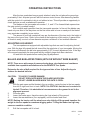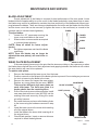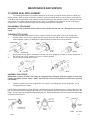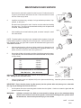
1
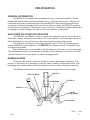
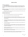
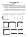
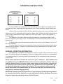
OPERATOR’S AND PARTS MANUAL
2030 TREE SPADE
SERIAL NUMBER: ___________________
MODEL NUMBER: ___________________
800-456-7100 I www.paladinattachments.com
Manual Number: OM684
Part Number: 75584
Rev.
503 Gay Street, Delhi, IA 52223, United States of America Copyright ©
10498
10-21-13-3
TABLE OF CONTENTS
PREFACE...........................................................................................................................................................3
SAFETY PRECAUTIONS
SAFETY STATEMENTS............................................................................................................................ 5
GENERAL SAFETY PRECAUTIONS.....................................................................................................5-7
EQUIPMENT SAFETY PRECAUTIONS................................................................................................... 8
DECALS
DECAL PLACEMENT................................................................................................................................ 9
DECALS............................................................................................................................................. 10-11
PRE-OPERATION. ........................................................................................................................................13
INSTALLATION.........................................................................................................................................14-15
operating instructions
controls........................................................................................................................................16-17
ball size guidlines.....................................................................................................................17-18
adjusting leg height..................................................................................................................... 19
balled and burlapped trees..................................................................................................19-20
direct transplanting.................................................................................................................... 20
storage & transporting.............................................................................................................. 21
maintenance AND SERVICE
GENERAL MAINTENANCE.................................................................................................................... 22
lubrication.........................................................................................................................................23
blade maintenance and sharpening........................................................................................ 23
replacing bushings........................................................................................................................ 23
blade adjustment & wear plate replacement..................................................................... 24
cylinder seal replacement...................................................................................................25-26
troubleshooting............................................................................................................................27-28
specifications
bolt torque specifications........................................................................................................ 29
tree spade specifications........................................................................................................... 30
limited warranty.................................................................................................................................. 31
PARTS
2030 tree spade assembly........................................................................................................32-35
mounting kits...............................................................................................................................36-37
power and return hydraulic circuit................................................................................38-39
blade hydraulic circuit..........................................................................................................40-41
gate hydraulic circuit.............................................................................................................42-43
gate cylinder assembly ..........................................................................................................44-45
blade cylinder assembly.........................................................................................................46-47
electrical valve assembly......................................................................................................48-49
valve assembly.............................................................................................................................50-51
solenoid valve replacement parts....................................................................................52-53
joystick and wire harness assembly.................................................................................54-55
wiring schematic for deutsch connectors........................................................................ 56
10521
75584
3-6-06
1
THIS PAGE
IS INTENTIONALLY
BLANK
2
75584
PREFACE
GENERAL COMMENTS
Congratulations on the purchase of your new BRADCO product! This product was carefully designed and manufactured to give you many years of dependable service. Only minor
maintenance (such as cleaning and lubricating) is required to keep it in top working condition.
Be sure to observe all maintenance procedures and safety precautions in this manual and on
any safety decals located on the product and on any equipment on which the attachment is
mounted.
This manual has been designed to help you do a better, safer job. Read this manual
carefully and become familiar with its contents. WARNING! Never let anyone operate this unit without reading the "Safety Precautions"
and "Operating Instructions" sections of this manual.
Always choose hard, level ground to park the vehicle on and set the brake
so the unit cannot roll.
Unless noted otherwise, right and left sides are determined from the operator’s control
position when facing the attachment.
NOTE: The illustrations and data used in this manual were current (according to the
information available to us) at the time of printing, however, we reserve the right to redesign and change the attachment as may be necessary without notification.
BEFORE OPERATION
The primary responsibility for safety with this equipment falls to the operator. Make
sure the equipment is operated only by trained individuals that have read and understand this
manual. If there is any portion of this manual or function you do not understand, contact your
local authorized dealer or the manufacturer.
SAFETY ALERT SYMBOL
This is the "Safety Alert Symbol" used by this industry. This symbol is used to
warn of possible injury. Be sure to read all warnings carefully. They are included
for your safety and for the safety of others working with you.
SERVICE
When servicing your product, remember to use only manufacturer replacement parts. Substitute parts may not meet the standards required for safe, dependable operation.
To facilitate parts ordering, record the model and serial number of your unit in the space
provided on the cover of this manual. This information may be obtained from the identification
plate located on the product.
The parts department needs this information to insure that you receive the correct parts
for your specific model.
10344 8-20-05
75584
3
THIS PAGE
IS INTENTIONALLY
BLANK
4
75584
SAFETY STATEMENTS
THIS SYMBOL BY ITSELF OR WITH A WARNING WORD THROUGHOUT THIS MANUAL IS USED TO CALL YOUR ATTENTION TO INSTRUCTIONS INVOLVING YOUR
PERSONAL SAFETY OR THE SAFETY OF OTHERS. FAILURE TO FOLLOW THESE
INSTRUCTIONS CAN RESULT IN INJURY OR DEATH.
DANGER
THIS SIGNAL WORD IS USED WHERE SERIOUS INJURY OR DEATH
WILL RESULT IF THE INSTRUCTIONS ARE NOT FOLLOWED PROPERLY.
WARNING
THIS SIGNAL WORD IS USED WHERE SERIOUS INJURY OR DEATH
COULD RESULT IF THE INSTRUCTIONS ARE NOT FOLLOWED PROPERLY.
CAUTION
THIS SIGNAL WORD IS USED WHERE MINOR INJURY COULD RESULT IF
THE INSTRUCTIONS ARE NOT FOLLOWED PROPERLY.
NOTICE
NOTICE INDICATES A PROPERTY DAMAGE MESSAGE.
GENERAL SAFETY PRECAUTIONS
WARNING! READ MANUAL PRIOR TO INSTALLATION
Improper installation, operation, or maintenance of this equipment could result in
serious injury or death. Operators and maintenance personnel should read this manual, as well as all manuals related to this equipment and the prime mover thoroughly
before beginning installation, operation, or maintenance. FOLLOW ALL SAFETY
INSTRUCTIONS IN THIS MANUAL AND THE PRIME MOVER’S MANUAL(S).
READ AND UNDERSTAND ALL SAFETY STATEMENTS
Read all safety decals and safety statements in all manuals prior to operating or
working on this equipment. Know and obey all OSHA regulations, local laws, and
other professional guidelines for your operation. Know and follow good work
practices when assembling, maintaining, repairing, mounting, removing, or operating
this equipment.
KNOW YOUR EQUIPMENT
Know your equipment’s capabilities, dimensions, and operations before operating.
Visually inspect your equipment before you start, and never operate equipment that
is not in proper working order with all safety devices intact. Check all hardware to
ensure it is tight. Make certain that all locking pins, latches, and connection devices
are properly installed and secured. Remove and replace any damaged, fatigued, or
excessively worn parts. Make certain all safety decals are in place and are legible.
Keep decals clean, and replace them if they become worn or hard to read.
10338
75584
8-16-05
5
GENERAL SAFETY PRECAUTIONS
WARNING! PROTECT AGAINST FLYING DEBRIS
Always wear proper safety glasses, goggles, or a face shield when driving pins in or
out, or when any operation causes dust, flying debris, or any other hazardous material.
WARNING! LOWER OR SUPPORT RAISED EQUIPMENT
Do not work under raised booms without supporting them. Do not use support material made of concrete blocks, logs, buckets, barrels, or any other material that could
suddenly collapse or shift positions. Make sure support material is solid, not decayed, warped, twisted, or tapered. Lower booms to ground level or on blocks. Lower
booms and attachments to the ground before leaving the cab or operator’s station.
WARNING! USE CARE WITH HYDRAULIC FLUID PRESSURE
Hydraulic fluid under pressure can penetrate the skin and cause serious injury or
death. Hydraulic leaks under pressure may not be visible. Before connecting or disconnecting hydraulic hoses, read your prime mover’s operator’s manual for detailed
instructions on connecting and disconnecting hydraulic hoses or fittings.
• Keep unprotected body parts, such as face, eyes, and arms as far away as
possible from a suspected leak. Flesh injected with hydraulic fluid may develop
gangrene or other permanent disabilities.
• If injured by injected fluid, see a doctor at once. If your doctor is not familiar with
this type of injury, ask him to research it immediately to determine proper treatment.
• Wear safety glasses, protective clothing, and use a piece of cardboard or wood
when searching for hydraulic leaks. DO NOT USE YOUR HANDS!
SEE ILLUSTRATION.
CARDBOARD
HYDRAULIC HOSE
OR FITTING
MAGNIFYING GLASS
10339
6
8-16-05
75584
GENERAL SAFETY PRECAUTIONS
WARNING! DO NOT MODIFY MACHINE OR ATTACHMENTS
Modifications may weaken the integrity of the attachment and may impair the function, safety, life, and performance of the attachment. When making repairs, use only
the manufacturer’s genuine parts, following authorized instructions. Other parts may
be substandard in fit and quality. Never modify any ROPS (Roll Over Protection
Structure) or FOPS (Falling Object Protective Structure) equipment or device. Any
modifications must be authorized in writing by the manufacturer.
WARNING! SAFELY MAINTAIN AND REPAIR EQUIPMENT
• Do not wear loose clothing or any accessories that can catch in moving parts. If
you have long hair, cover or secure it so that it does not become entangled in the
equipment.
• Work on a level surface in a well-lit area.
• Use properly grounded electrical outlets and tools.
• Use the correct tools for the job at hand. Make sure they are in good condition for
the task required.
• Wear the protective equipment specified by the tool manufacturer.
SAFELY OPERATE EQUIPMENT
Do not operate equipment until you are completely trained by a qualified operator
in how to use the controls, know its capabilities, dimensions, and all safety requirements. See your machine’s manual for these instructions.
• Keep all step plates, grab bars, pedals, and controls free of dirt, grease, debris,
and oil.
• Never allow anyone to be around the equipment when it is operating.
• Do not allow riders on the attachment or the prime mover.
• Do not operate the equipment from anywhere other than the correct operator’s
position.
• Never leave equipment unattended with the engine running, or with this attachment in a raised position.
• Do not alter or remove any safety feature from the prime mover or this attachment.
• Know your work site safety rules as well as traffic rules and flow. When in doubt
on any safety issue, contact your supervisor or safety coordinator for an explanation.
10340
75584
8-16-05
7
EQUIPMENT SAFETY PRECAUTIONS
WARNING! KNOW WHERE UTILITIES ARE
Observe overhead electrical and other utility lines. Be sure equipment will clear
them. When digging, call your local utilities for location of buried utility lines, gas,
water, and sewer, as well as any other hazard you may encounter.
OPERATING THE TREE SPADE
•
•
•
•
•
•
•
Block off work area from bystanders, livestock, etc.
Operate only from the operator’s station.
Do not lift loads in excess of the capacity of the prime mover.
When operating on slopes, drive up and down, not across. Avoid steep hillside
operation, which could cause the prime mover to overturn.
Reduce speed when driving over rough terrain, on a slope, or turning, to avoid
overturning the vehicle.
An operator must not use drugs or alcohol, which can change his or her alertness or coordination. An operator taking prescription or over-the-counter drugs
should seek medical advice on whether or not he or she can safely operate
equipment.
Before exiting the prime mover, lower the attachment to the ground, turn off the
prime mover’s engine, remove the key and apply the brakes.
TRANSPORTING THE TREE SPADE
•
•
•
•
Travel only with the attachment in a safe transport position to prevent uncontrolled movement. Drive slowly over rough ground and on slopes.
When driving on public roads use safety lights, reflectors, Slow Moving Vehicle
signs etc., to prevent accidents. Check local government regulations that may
affect you.
Do not drive close to ditches, excavations, etc., cave in could result.
Do not smoke when refueling the prime mover. Allow room in the gas tank for
expansion. Wipe up any spilled fuel. Secure cap tightly when done.
MAINTAINING THE TREE SPADE
•
•
•
•
•
Before performing maintenance, lower the attachment to the ground, turn off the
engine, remove the key and apply the brakes.
Never perform any work on the attachment unless you are authorized and qualified to do so. Always read the operator service manual’s before any repair is
made. After completing maintenance or repair, check for correct functioning of
the attachment. If not functioning properly, always tag “DO NOT OPERATE” until
all problems are corrected.
Worn, damaged, or illegible safety decals must be replaced. New safety decals
can be ordered from BRADCO.
Never make hydraulic repairs while the system is under pressure. Serious personal injury or death could result.
Never work under a raised attachment.
10502
8
2-28-06
75584
DECALS
DECAL PLACEMENT
GENERAL INFORMATION
The diagram on this page shows the location of the decals used on the BRADCO 2030
Tree Spade. The decals are identified by their part numbers, with reductions of the actual decals located on the following pages. Use this information to order replacements for lost or damaged decals. Be sure to read all decals before operating the tree spade. They contain information you need to know for both safety and attachment longevity.
#40653
#40151
#4338
#40752
#40149
#40652
#40651
#40150
#40753
#40646
#40424
#40652
#40653
#40660
#40424
#40494
#40440
SERIAL TAG LOCATION
IMPORTANT: Keep all safety signs clean and legible. Replace all missing, illegible or damaged safety signs.
When replacing parts with safety signs attached, the safety signs must also be replaced.
REPLACING SAFETY DECALS: Clean the area of application with a nonflammable solvent, then wash the same
area with soap and water. Allow the surface to dry. Remove the backing from the safety sign, exposing the adhesive surface. Apply the safety sign to the position shown in the diagram above and smooth out any bubbles.
10504
75584
2-28-06
9
DECALS
1 2 3 0
NUMBER “1”
PART #40651
NUMBER “2”
PART #40652
NUMBER “3”
PART #40653
NUMBER “0”
PART #40660
REAR STABILIZER
#40646
REAR STABILIZER
PART #40646
MADE IN USA
MADE IN USA
PART #4338
BRADCO LOGO
PART #40424
OPERATION DECAL
PART #40752
CAUTION! CYLINDER DAMAGE
PART #40753
10503
10
2-28-06
75584
DECALS
DANGER! PINCH POINT
PART #40149
WARNING! HIGH PRESSURE FLUID
PART #40151
WARNING! READ MANUAL
PART #40150
CALL BEFORE YOU DIG
PART #40440
DANGER! ELECTRICAL HAZARD
PART #40494
9469
75584
2-28-06-2
11
THIS PAGE
IS INTENTIONALLY
BLANK
12
75584
PRE-OPERATION
GENERAL INFORMATION
The BRADCO tree spades were designed to be easy to use and maintain. They are
powered by the skid-steers auxiliary hydraulics and a 12 DC electrical source. They are controlled with a joystick and electrical valve. Although BRADCO does offer various options for
connecting to existing electrical joystick controls, we will be covering the BRADCO operating
controls in these instructions. The joystick control consists of 5 momentary toggle switches and
is equipped to handle 3 blades, the gate and the rear stabilizers (if equipped).
SKID-STEER OR OTHER HOST MACHINE
The BRADCO Tree Spades mount to various host machines such as, but not limited to
skid-steers, loaders, tractors and excavators. Due to the quantity of skid-steer applications, we
will be referring to the host machine as a skid-steer loader throughout this manual.
The skid-steer must have front auxiliary hydraulics and a 12 Volt DC electrical power
source available for spade operation. The BRADCO Tree Spades are NOT designed for use
on high flow skid-steers.
Rear stabilizers are recommended to get the maximum performance of your tree spade.
The rear stabilizers allow as much weight as possible to be transferred to the front of the skidsteer and therefore to the tree spade for maximum digging ability.
NOMENCLATURE
Throughout this manual, reference is made to various attachment components. The
purpose of this section is to acquaint you with the various names of these components. This
knowledge will be helpful when reading through the manual or when ordering service parts.
The blades are identified in a clockwise direction starting with the left rear spade.
gate cylinder
blade #3
mainframe
blade #1
blade #2
VALVE
(INSIDE frame)
leg support
gate
10510
75584
3-1-06
13
INSTALLATION
GENERAL INFORMATION
The following instructions will assist you in mounting your tree spade onto your skidsteer loader. The tree spade uses the quick attach mechanism for ease of installation. Therefore, if you know how to attach the loader bucket, attaching the tree spade should prove no
problem.
NOTE: For mounting to other host machines see the specific mounting instructions that
are supplied separately.
Remember to read all safety warnings, decals and operating instructions before operating the skid-steer loader or tree spade.
MOUNTING INSTRUCTIONS
1.
Remove the steel shipping banding from around the tree spade and the skid.
2.
Remove any attachment from the front of the skid-steer loader.
3.
Set the quick attach locks on the skid-steer toolbar to the unlocked position. Lower the
loader arms and tilt the toolbar down low enough to pass under the top lip of the hitch
on the mainframe.
4.
Following all standard safety practices, start the skid-steer and slowly drive it in back of
the attachment. Position the loader so the top of the toolbar under the lip of the hitch on
the mainframe.
5.
Tilt the toolbar back to hook the attachment onto the toolbar. It may be necessary to lift
the loader arms slightly.
6.
Set the quick attach locks to the locked position to secure the tree spade onto the loader. It may be necessary to raise lower or tilt the toolbar to properly align so the locking
mechanism can be activated.
7.
Install your rear stabilizers (if so equipped) by following the instructions that were supplied rear stabilizers for your unit.
8.
Connect the power and return hoses for the rear stabilizers to the two 90° elbows (part
#3434) on the left side of the valve assembly.
9.
With the auxiliary hydraulic system turned off, route the hydraulic hoses over the mainframe and connect them to their proper auxiliary couplers on the loader.
10508
14
3-1-06
75584
INSTALLATION
10.
Connect the joystick assembly to the control cord from the tree spade. Connect the
power cord from the joystick control to a power source on the skid-steer. NOTE: There
is an optional power plug adapter available for connecting to an auxiliary power
outlet such as a cigarette lighter. Some host machines have an auxiliary electrical
outlet to plug in the control cord and then use their own joystick controls.
DANGER!
ELECTROCUTION HAZARD
Provide electrical power to the joystick by following your skid-steer manufacturer's recommended procedures. The electrical circuit must be fused
with a 10 amp fuse to prevent machine damage and serious personal injury
or death.
11.
Use plastic ties to secure the control cord extending from the tree spade mainframe to
the hydraulic hoses to help keep it from interfering with operation of the tree spade and
also to assist in keeping it free from pinching or chafing.
12.
Complete the pre-delivery checklist located in the back of this manual. Tree Spade installation is now complete.
10509
75584
3-1-06
15
OPERATING INSTRUCTIONS
CONTROLS
GENERAL INFORMATION
Your tree spade is controlled by a joystick and an electrical valve assembly. Although
BRADCO does offer various options for connecting to existing electrical joystick controls, we
will be covering the BRADCO operating controls in these instructions. The joystick control
consists of 5 momentary toggle switches and is equipped to handle three blades, the gate and
rear stabilizers (if equipped).
BLADE CONTROLS
The joystick control can accommodate three blades and is wired for the number of blades
on the tree spade you have purchased. Pushing the toggle switch up will raise that specific blade
up, and pushing the toggle switch down will lower that blade. When the toggle switch is released,
all movement will stop. The blade controls are located in the same pattern as the blades on the
unit , with blade Number 1 being the closest blade to the operator on the left hand side (left rear
blade).
BLADE #2
BLADE #1
REAR STABILIZERS
UP
UP
DOWN
DOWN
UP
OPEN
DOWN
CLOSED
BLADE #3
GATE
UP
DOWN
GATE CONTROL
The gate control operates in the same fashion as the blade controls. Pushing the toggle
switch up will open the gate and pushing the toggle switch down will close the gate. When the
toggle switch is released all movement will stop.
10511
16
3-1-06
75584
OPERATING INSTRUCTIONS
CONTROLS
REAR "JACK" STABILIZER CONTROL
The rear stabilizer control operates in the same fashion as the other controls. Pushing the
toggle switch up will raise the left and right stabilizers and pushing the toggle switch down will
lower the left and right stabilizer. When the toggle switch is released all movement will stop.
Rear stabilizer kits are available from your BRADCO dealer for fit up to various skid-steer
loaders. The rear stabilizer hoses connect to the tree spade control valve and are therefore controlled by the operating control switch on the joystick.
Rear stabilizers are recommended to get the maximum performance from your tree spade.
The rear stabilizers allow as much weight as possible to be transferred to the front of the skidsteer and therefore to the tree spade for maximum digging ability.
BALL SIZE GUIDELINES
The following information will assist you in determining the size of ball needed for the job at
hand. These charts (taken from the American Standard for Nursery Stock - ANSI Z60.1-1996) are to be used
as a guideline only and you should contact your local nursery for more detailed instructions.
Multi-Stem Trees or Shrubs
Height
Deciduous Shrubs
Min. Dia. Ball
Height
4'
14"
5'
16"
6'
18"
7'
20"
8'
22"
12"
18"
2'
3'
4'
5'
6'
7'
Small Trees
(Ht. up to 6' / Caliper 6' & over)
Ht./Caliper Min. Dia. Ball
12"
18"
2'
3'
4'
5'
6'
7'
75584
8"
1/2"
9"
3/4"
10"
1"
12"
1-1/4"
14"
1-1/2"
16"
1-3/4"
18"
20"
Min. Dia. Ball
12"
14"
16"
18"
20"
22"
Coniferous Evergreens
Conical & Broad Uprights
Spread
Min. Dia. Ball
Height
Min. Dia. Ball
9"
12"
15"
18"
2'
2-1/2'
3'
3-1/2'
4'
8"
8"
10"
10"
12"
14"
16"
18"
21"
12"
18"
2'
3'
4'
5'
6'
10"
10"
12"
14"
16"
20"
22"
olumnar Coniferous Evergreens
C
Regular Growing
Caliper
Coniferous Evergreens
Spreading/Semi-Spreading/Globe/Dwarf
2'
10"
3'
12"
4'
14"
5'
16"
3/4"
16"
1"
18"
1-1/2"
20"
1-3/4"
22"
Height
Min. Dia. Ball
Shade Trees
Min. Dia. Ball
Columnar Coniferous Evergreens
Rapid Growing
Height
Min. Dia. Ball
10"
12"
8"
10"
2'
9"
12"
3'
11"
13"
4'
12"
14"
5'
14"
16"
6'
16"
18"
20"
Broadleaf Evergreen
Cone and Upright
Height
Min. Dia. Ball
18"
2'
3'
4'
5'
6'
10"
12"
14"
16"
20"
22"
10512
3-1-06
17
OPERATING INSTRUCTIONS
Broadleaf Evergreen
Spreading/Semi-Spreading/
Processed Balled
Globe/Dwarf
Fruit Trees
Spread
Min. Dia. Ball
18"
10"
2'
12"
2-1/2'
14"
3'
16"
3-1/2'
18"
4'
21"
Caliper
Min. Dia. Ball
1/4"
5/16"
3/8"
31/2"
5/8"
3/4"
1" & UP
8"
8"
10"
10"
10"
12"
12"
In sizing shade trees, caliper shall take precedence over height. In size grading small
and flowering trees, height shall take precedence up to 6 feet; thereafter, caliper takes precedence.
Caliper of the trunk shall be taken 6 inches above the ground up to and including 4 inch
caliper size, and 12 inches above the ground for larger sizes. (Seldom are tree trunks perfectly
round. Caliper measurement may be taken with "slot" type caliper, "pincer" type calipers or
diameter tape.)
The diameter of the ball is determined by the blade size or the digging depth. Each
blade is changed by removing one pin. The ball depth is determined by the position of the adjustable legs.
On larger bushy trees the branches may have to be tied up so the blades do not cut off
the lower branches.
On some types of trees it is recommended for best results that transplanting take place
while the tree is dormant. Contact your local nursery for the specifications on the type of tree
you are transplanting.
GENERAL OPERATING INFORMATION
The BRADCO Tree Spades are designed to meet the needs of the professional nurseryman. The machine has proven capable of continuous digging with a minimum of maintenance.
It is used extensively for removing trees for burlapping and for transplanting and rearranging
nursery rows.
NOTE: These instructions include the use of rear "jack" stabilizers. Rear stabilizer kits
are available from your BRADCO dealer for fit up to various skid-steer loaders. The rear
stabilizer hoses connect to the tree spade control valve and are therefore controlled by
the operating control switch on the joystick. Rear stabilizers are recommended to get
the maximum performance from your tree spade. The rear stabilizers allow as much
weight as possible to be transferred to the front of the skid-steer and therefore to the
tree spade for maximum digging ability.
IMPORTANT: Always follow the instructions in your skid-steer loader operators manual
for operating the auxiliary hydraulic controls and follow the Safety Shutdown Procedure
whenever leaving the operators station of the skid-steer.
10513
18
3-1-06
75584
OPERATING INSTRUCTIONS
After the tree spade has been properly attached, raise the unit above the ground approximately 2 feet. Acquaint yourself with the various control levers. After becoming familiar
with the controls it is advisable to dig in soil without a tree. This will provide an opportunity to
check ball size as well as attachment operation.
The blades on the tree spade are number 1, 2, and 3. The forward blade opens when
the gate control is pushed forward.
Soil condition and type affect how the tree spade operates. In firm soil the blades may
travel only one-third of the way down on the first stroke and in loose or sandy soil the blades
may penetrate completely in one stroke.
The amount of root ball needed will vary per the diameter of the tree trunk, the height of
the tree or the type of tree. Refer to the charts at the beginning of this section. A general rule
of thumb is every one inch of tree diameter requires a minimum of ten inch ball diameter.
Adjusting Leg Height
The tree spades are equipped with adjustable legs that are used for adjusting the ball
size. With the legs fully raised the ball size will be the rated size of your tree spade. Moving the
legs down will decrease the ball size approximately 2.00" for each adjustment hole. If the legs
are removed completely the tree spade will dig a slightly larger hole than rated size.
Lift and block the spade before making any leg adjustment.
Balled and Burlapped Trees (with or without Wire Basket)
NOTE: There are a wide range of presewn burlap bags, wire baskets and containers
available from reputable manufacturers for the BRADCO Tree Spade.
Determine the size of ball required for the type and size of tree. Adjust the legs to
achieve the desired ball size.
CAUTION: TO AVOID CYLINDER DAMAGE:
Do not open gate when the blades are down.
Do not lower blades when the gate IS open.
1.
2.
3.
4.
With the gate open and the blades in the up position, center the tree in the tree spade
from left to right: and front to back. NOTE: It is CRITICAL that the tree is centered in
the ball. Therefore, it is advisable to have someone on the ground to aid in the
alignment process.
Close the gate.
Lower the loader arms, therefore raising the front wheels off the ground.
Lower the rear stabilizers (if so equipped), until the loader feels level.
NOTE: Raising the loader until the wheels are only slightly off the ground transfers the
weight to the tree spade for maximum digging power. Lifting the loader too high may
cause an unstable condition.
5.
Roll the tree spade until it is level.
10514
75584
3-2-06
19
OPERATING INSTRUCTIONS
6.
7.
8.
9.
10.
11.
12.
13.
14.
15.
Once the tree spade is level, the loader raised slightly and the gate closed, it is time to
start lowering the blades. Using the joystick control, lower "Blade 1" as far as it will go
into the soil. (Due to the different soil conditions the blade may go all the way into the
ground or only slightly.)
As soon as the blade starts to tilt the attachment, stop movement and raise the blade
slightly to remove some of the down pressure. (This will assist in digging the maximum
ball size and prevent digging an angled hole.)
Using the joystick control, lower "Blade 2" as far as it will go into the soil. As soon as the
blade starts to tilt the attachment, stop movement and raise the blade slightly to remove
some of the down pressure. Repeat for “Blade 3).
If the blades failed to lower completely due to the soil conditions, repeat Steps #6 thru
#8 until all the blades are completely lowered into the soil.
Raise the rear stabilizers, (if so equipped).
Raise the loader arms until the wheels are fully on the ground. Lift the tree out of the
hole.
Placing the burlap on the ground or in the wire basket, position the tree in the center of
the burlap. NOTE: Carry the tree as low as possible when transporting.
Release the ball by first raising "Blade 3", and continue to raise the blades in reverse
order 2, & 1. NOTE: If the tree ball sticks to the blades, use a shovel to press down
on the tree ball to loosen it from the blades.
Lift the tree spade slightly, and open the gates. Back the loader away from the tree. The
ball is ready for covering, with no additional shaping necessary.
Finish wrapping the tree.
Direct Transplanting
1.
Determine the size of hole needed for the tree you are transplanting, and adjust the legs
to achieve the desired hole size.
Raise the blades and drive the skid steer to the location that the tree will be planted and
position the skid-steer so the loader is as level as possible. Follow Steps 2 thru 11 in the
previous instructions (Balled and Burlapped Trees) to dig a spot for the tree.
Lift the dirt ball out of the ground and move out of the way for tree transplanting. Set the
tree spade on the ground and raise the blades to release the dirt ball. The blades should
be raised in reverse order 3, 2 and 1. Open gate.
See Steps 1 thru 11 in the previous instructions (Balled and Burlapped Trees) to dig up
the desired tree for transplanting.
Position the tree over the previously dug hole, and while keeping the tree trunk as vertical as possible, lower the tree.
Release the ball by first raising "Blade 3" and continue to raise the blades in reverse
order 2, & 1. NOTE: If the tree ball sticks to the blades, use a shovel to press down
on the tree ball to loosen it from the blades.
Lift the tree spade slightly and open the gate. Back the loader away from the tree.
NOTE: Follow any specific transplanting instructions, such as watering and mulching
etc., for the type of tree you are transplanting.
2.
3.
4.
5.
6.
7.
10515
20
3-2-06
75584
OPERATING INSTRUCTIONS
GENERAL INFORMATION
The following storage procedure will help you to keep your attachment in top condition.
It will also help you get off to a good start the next time your tree spade is needed. We therefore, strongly recommend that you take the extra time to follow these procedures whenever
your attachment will not be used for an extended period of time.
PREPARATION FOR STORAGE
1.
2.
3.
4.
5.
6.
7.
8.
9.
10.
Clean the exterior thoroughly removing all mud, dirt and grease.
Inspect the unit for visible signs of wear. Order any parts required and make any necessary repairs to avoid delays when starting next season.
Inspect the graphite coating on the blades. Repaint as needed.
Check the blades for wear. If sharpening is required use a hand grinder.
Tighten all loose nuts and capscrews.
Grease all grease fittings.
Coat the exposed portions of the cylinder rods with grease.
Connect the hydraulic couplers together to protect the hydraulic system from contaminates. (Cap the fittings for the rear stabilizers.)
Replace decals if damaged or in unreadable condition.
Store the unit in a dry and protected place. Leaving the unit outside will materially shorten its life.
REMOVING FROM STORAGE
1.
2.
Remove all protective coverings.
Check hydraulic hoses for deterioration and replace if necessary.
TRANSPORTING
1.
2.
3.
Follow all federal, state and local regulations when transporting the unit on public roads.
Use extra care when loading or unloading the machine onto a trailer or truck.
Before transporting, raise the blades and keep the unit as close to the ground as possible.
CAUTION! Be sure to install a SMV (Slow Moving Vehicle) sign on the loader before attempting to transport.
When transporting on a road or highway at night or during the day, use accessory lights and devices for adequate warning to the operators of other
vehicles. In this regard, check local government regulations.
Always drive slowly over uneven terrain to avoid tipping the unit.
10518
75584
3-6-06
21
MAINTENANCE AND SERVICE
GENERAL INFORMATION
Regular maintenance is the key to long equipment life and safe operation. Maintenance
requirements have been reduced to an absolute minimum. However, it is very important that
these maintenance functions be performed as described below.
LUBRICATION
Lubricate all grease fittings with a multi-purpose grease.
DAILY
Physically check all pins, bushings, cotter pins, nuts, etc., for signs of wear or loose fit. Tighten as required, replace where necessary.
Clean equipment of all dirt, oil, and excess grease.
Check for missing or illegible Safety / Warning Decals.
Check all fittings and hydraulic hoses for leaks.
WARNING! Escaping hydraulic / diesel fluid under pressure can penetrate the skin
causing serious injury. Fluid escaping from a very small hole can be almost
invisible. Use a piece of cardboard or wood, rather than hands to search for
suspected leaks.
Keep unprotected body parts, such as face, eyes, and arms as far away as
possible from a suspected leak. Flesh injected with hydraulic fluid may develop gangrene or other permanent disabilities. If injured by injected fluid,
see a doctor at once.
Stop the engine and relieve pressure before connecting or disconnecting
lines.
Tighten all connections before starting engine or pressurizing lines.
CARDBOARD
HYDRAULIC HOSE
OR FITTING
MAGNIFYING
GLASS
9451
22
3-3-06-2
75584
MAINTENANCE AND SERVICE
WARNING! Be sure to follow Safety Shutdown Procedures before performing
any maintenance on attachment.
LUBRICATION
Lubricate all grease fittings daily or after every 8 hours of operation. There are three grease
fittings on the 2030 tree spade. One on each end of the Gate Cylinder and one on the Gate Pivot
Pin. NOTE: A scraping sound during operation is an indication that the slide channel and
slider bars require lubricating.
BLADE MAINTENANCE
Maintaining the condition of the blades will result in a cleaner ball and a smoother digging
operation. The blades are painted before shipping. This prevents the earth from sticking to the blades
and aids in the digging operation. The performance of the blade is affected by soil conditions and can
be repainted or coated with Slip Plate #1, manufactured by Acrotech Industries Inc. One gallon of Slip
Plate #1 can be purchased from BRADCO under part #25154. It is important that oil not be used on
the blades as long as the graphite coating remains.
SHARPENING BLADES
Although the blades should remain in good condition for a long time, extensive use and rocky
soil conditions may dull portions of the blades. If sharpening is required, use a hand grinder and
sharpen the blades in an even pattern.
REPLACING BUSHINGS
To Replace Arm Bushings:
1.
Lower the mainframe onto the rear legs as close to the ground as possible, and block up the
front of the mainframe to keep it level.
2.
Remove Blades #2 and #3.
3.
Disconnect the gate cylinder at the arm weldment.
4.
Attach a hoist to the arm to prevent it from falling and causing cylinder damage, personal
injury or undue stress to the hoses when it is disconnected from the mainframe.
NOTE: If you are removing the arm completely for bushing replacement, the blade
cylinder hoses will need to be tagged and
removed.
5.
With the arm supported, remove the
pivot pin securing the arm to the mainframe. While continuing to support
the arm, press out the top and bottom
bushing and replace with new.
6.
Position the arm, and replace the pivot
pin.
7.
Connect the gate cylinder to the arm
weldment.
8.
Reinstall Blades #2 and #3.
Bushing replacement is complete.
MAINFRAME
PIVOT PIN
HOIST / SLING
ARM
LEG
BUSHINGS
BLOCK
GATE CYLINDER
10516
75584
3-3-06
23
MAINTENANCE AND SERVICE
BLADE ADJUSTMENT
Proper adjustment of the blades is required for best performance of the tree spade. Loose
blades hinder the spades ability to cut the roots. As the blades and plastic wear plates begin to wear,
the blades may need to be adjusted to maintain the close positioning of the blades and prevent gapping between the blades. There are shims provided between the tower and the blades and the tower
and the tower cover that can be removed (to tighten the tower on the mainframe) or moved to the
opposite side (to maintain blade tightness).
TOWER
To adjust blades:
TOWER
1.
Loosen the .50" capscrews securing the
COVER
tower cover and blades to the tower.
2.
Slide in a shim or remove a shim as required
SHIMS
to maintain blade tightness.
(NOTE: Keep all shims for future adjustments.)
BLADE
3.
Re-tighten capscrews and check the blade
positioning.
NOTE: Once the blades can no longer be
adjusted the wear plate(s) will need to be replaced.
WEAR PLATE REPLACEMENT
WEAR PLATES
If the wear plate(s) have worn to the point that the towers are riding on the capscrews or when
the blades have reached the end of their adjustment and gapping between the blades is still evident
the wear plate(s) will need to be replaced.
To replace wear plates:
1.
Remove the blade and the tower cover from the tower.
2.
Position a wrench on the flat spot of the blade cylinder to prevent it from rotating as you remove
the lock nut securing the blade to the tower.
3.
Remove the tower and inspect the wear plates.
Replace any wear plates that are worn. NOTE:
MAINFRAME
There are two different style wear plates on
BLADE CYLINDER
each slide tower. The front wear plate is a
harder plastic than the remaining three.
RIVET (#10104)
4.
Drill out the rivets to remove the wear plate. Install
new wear plate with new rivets (#10104) into the
existing holes and secure by driving the center
pin with a hammer.
5.
Re-install the tower and secure the blade cylinder
to the tower using the hardware removed in step
#2.
6.
Install the tower cover to the tower while inserting
all of the original shims.
7.
Install the blade to the tower while inserting all of
the original shims.
8.
Check blade position. Insert or remove shims as
WEAR PLATES
required to obtain blade tightness.
10517
24
3-3-06
75584
MAINTENANCE AND SERVICE
CYLINDER SEAL REPLACEMENT
The following information is provided to assist you in the event you should need to repair or rebuild a hydraulic cylinder. When working on hydraulic cylinders, make sure that the work area and tools are clean and free
of dirt to prevent contamination of the hydraulic system and damage to the hydraulic cylinders. Always protect the
active part of the cylinder rod (the chrome section). Nicks or scratches on the surface of the rod could result in
cylinder failure. Clean all parts thoroughly with a cleaning solvent before reassembly.
DISASSEMBLY PROCEDURE
IMPORTANT: Do not contact the active surface of the cylinder rod with the vise. Damage to the rod could
result.
THREADED TYPE GLAND
1. 2.
3.
4.
Rotate the gland with a spanner wrench counterclockwise until the gland is free of the cylinder tube.
Pull the cylinder rod from the cylinder tube and inspect the piston and the bore of the cylinder tube for
deep scratches or galling. If damaged, the piston AND the cylinder tube must be replaced.
Remove the hex nut, piston, flat washer or spacer tube (if so equipped), and gland from the cylinder rod. If
the cylinder rod is rusty, scratched, or bent, it must be replaced.
Remove and discard all the old seals.
ASSEMBLY PROCEDURE
IMPORTANT: Replace all seals even if they do not appear to be damaged. Failure to replace all seals may
result in premature cylinder failure. NOTE: Seal kits will service most cylinders of similar bore size and
rod diameter.
1.
Install the cylinder rod seal in the gland first. Be careful not to damage the seal in the process, as it is
somewhat difficult to install.
NOTE: A special installation tool (Part #65349) is available to help with installing the seal. Simply fit the end of the
tool over the seal so that the large prong of the tool is on the outside of the seal, and the two smaller prongs on the
inside. The lip of the seal should be facing towards the tool. Rotate the handles on the tool around to wrap the seal
around the end of the tool.
10356
75584
10-13-05
25
MAINTENANCE AND SERVICE
Now insert the seal into the gland from the inner end. Position the seal in
its groove, and release and remove the tool. Press the seal into its seat
the rest of the way by hand.
2.
Install the new piston ring, rod wiper, O-rings and backup washers, if applicable, on the piston.
Be careful not to damage the seals. Caution must be used when installing
the piston ring. The ring must be stretched carefully over the piston with
a smooth, round, pointed tool.
3.
After installing the rod seal inside the gland, as shown in step #1, install
the external seal.
NOTE: Threaded glands may have been equipped with a separate O-ring and
backup washer system or a polypak (all in one) type seal. Current seal kits contain a polypak (all in one) type seal to replace the discarded seal types on ALL
THREADED GLANDS.
4.
Slide the gland onto the cylinder rod, being careful not to damage the rod
wiper. Then install the spacer, or flat washer (if so equipped), small o-ring,
piston, and hex nut onto the end of the cylinder rod.
5.
Secure the cylinder rod (mounting end) in a vise with a support at its center.
Torque the nut to the amount shown for the thread diameter of the cylinder
rod (see chart).
Thread Diameter
7/8"
*1"
1-1/8"
1-1/4"
1-3/8"
POUNDS - FEET
150-200
230-325
350-480
490-670
670-900
* 1" Thread Diameter WITH 1.25" Rod Diameter
Min. 230 ft. lbs.
Max. 250 ft. lbs.
IMPORTANT: Do not contact the active surface of the cylinder rod with the
vise. Damage to the rod could result.
6.
Apply a lubricant (such as Lubriplate #105) to the piston and teflon ring. Insert the cylinder rod assembly
into the cylinder tube.
IMPORTANT: Ensure that the piston ring fits squarely into the cylinder tube and piston groove, otherwise
the ring may be damaged and a leak will occur.
7.
Use a spanner wrench to rotate the gland clockwise into the cylinder. Continue to rotate the gland with the
spanner wrench until it is tight.
WARNING!
Cylinders serviced in the field are to be tested for leakage prior to the attachment being
placed in work. Failure to test rebuilt cylinders could result in damage to the cylinder and/or
the attachment, cause severe personal injury or even death.
10357
26
10-13-05
75584
TROUBLESHOOTING
PROBLEM
Tree Spade will not operate.
Blades activate sluggishly.
Leaking Oil.
Insufficient power.
Cylinders operate in the
wrong direction.
POSSIBLE CAUSE
POSSIBLE REMEDY
Auxiliary hoses not hooked up to the
skid-steer.
Engage Couplers
Obstruction in hydraulic lines.
Remove obstruction and replace if necessary.
Skid-steer auxiliary valve not engaged.
Engage auxiliary valve.
Loss of electrical power to joystick
control.
Check electrical connection
and circuit fuse.
Insufficient hydraulic flow from the
skid-steer.
Refer to skid-steer's owners
manual.
Damaged quick coupler.
Replace if necessary.
Oil filter on skid-steer is dirty.
Refer to skid-steer's owners
manual.
Loose or damaged hydraulic line.
Tighten or replace.
O-Rings on fittings damaged.
Replace if necessary.
Fittings loose or damaged.
Tighten or replace.
Cylinder seals damaged.
Replace cylinder seals.
Insufficient hydraulic flow from the
skid-steer.
Refer to skid-steer's owners
manual.
Relief valve setting adjusted too low.
Refer to skid-steer's owners
manual.
Oil filter on skid-steer is dirty.
Refer to skid-steer's owners
manual.
Blades worn or chipped.
Sharpen as needed.
Hoses from the valve to the skid-steer
incorrectly connected.
Switch couplers at the skid
steer end.
Incorrect wiring from the joystick
control.
Check wiring diagram and
correct.
10519
75584
3-6-06
27
TROUBLESHOOTING
PROBLEM
Excessive oil temperature.
POSSIBLE CAUSE
Hydraulic oil level too low.
Obstruction in hydraulic lines.
Remove obstruction and replace if
necessary.
Hydraulic oil or oil filter in skid-steer
is dirty.
Refer to skid-steer's owners
manual.
Relief valve setting adjusted too low.
Refer to skid-steer's owners manual.
Couplers not engaged.
A hydraulic cylinder not
operating.
All hydraulic cylinders not
functioning.
Hydraulic cylinders only
operating in one direction.
POSSIBLE REMEDY
Refer to skid-steer's owners manual
Engage couplers.
Insufficient hydraulic flow from the
skid-steer.
Refer to skid-steer's owners manual.
Cylinder rod bent.
Visually inspect the cylinder for
damage.
Cylinder seals damaged.
Replace cylinder seals.
Obstruction in hydraulic lines.
Remove obstruction and replace if
necessary.
An electrical coil not functioning at
valve.
Check voltage readings at valve
and replace coil if necessary.
Blown fuse on skid-steer.
Refer to skid-steer's owners manual.
Damaged electrical wiring.
Test and replace if necessary.
Loss of hydraulic power.
Check hydraulic circuit.
Electrical power connected to
wrong polarity.
Reverse red and black wires.
Contaminants in the hydraulic system
and solenoid valve.
Remove spool from solenoid valve
and check for foreign material.
Clean or replace.
Remove spool from solenoid valve
and check seals for damage. Replace if necessary.
Damaged electrical wiring.
Test and replace if necessary.
Bad electrical connection at Reversing
valve.
Check connections and correct.
Coil or spool damaged in reversing
valve.
Replace as necessary.
10520
28
3-6-06
75584
BOLT TORQUE
BOLT TORQUE SPECIFICATIONS
GENERAL TORQUE SPECIFICATION TABLE
Use the following torques when special torques are not given. These values apply to fasteners as
received from suppliers, dry, or when lubricated with normal engine oil. They do not apply if special graphited or
moly disulphide greases or other extreme pressure lubricants are used. This applies to both UNF and UNC
threads. Remember to always use grade five or better when replacing bolts.
IMPORTANT: On all PLATED GRADE 8 bolts, reduce torque 15% from listed bolt torque specification.
SAE Grade No.
Bolt head identification
marks as per grade.
NOTE: Manufacturing
Marks Will Vary
2
5
TORQUE
Bolt Size
Inches
Millimeters
Pounds Feet
Min.
Max.
8*
TORQUE
Newton-Meters
Min.
Max.
Pounds Feet
Min.
Max.
TORQUE
Newton-Meters
Min.
Max.
Pounds Feet
Min.
Max.
Newton-Meters
Min.
Max.
1/4
6.35
5
6
7
8
9
11
12
15
12
15
16
20
5/16
7.94
10
12
14
16
17
20.5
23
28
24
29
33
39
3/8
9.53
20
23
27
31
35
42
48
57
45
54
61
73
7/16
11.11
30
35
41
47
54
64
73
87
70
84
95
114
1/2
12.70
45
52
61
70
80
96
109
130
110
132
149
179
9/16
14.29
65
75
88
102
110
132
149
179
160
192
217
260
5/8
15.88
95
105
129
142
150
180
203
244
220
264
298
358
3/4
19.05
150
185
203
251
270
324
366
439
380
456
515
618
7/8
22.23
160
200
217
271
400
480
542
651
600
720
814
976
1
25.40
250
300
339
406
580
696
787
944
900
1080
1220
1464
1-1/8
25.58
-
-
-
-
800
880
1085
1193
1280
1440
1736
1953
1-1/4
31.75
-
-
-
-
1120
1240
1519
1681
1820
2000
2468
2712
1-3/8
34.93
-
-
-
-
1460
1680
1980
2278
2380
2720
3227
3688
1-1/2
38.10
-
-
-
-
1940
2200
2631
2983
3160
3560
4285
4827
* Thick Nuts must be used with Grade 8 bolts
METRIC BOLT TORQUE SPECIFICATIONS
Coarse Thread
Size of Screw
Grade No.
Ptich (mm)
Newton-Meters
3.6-5.8
4.9-7.9
5.8-.4
7.9-12.7
10.9
7.2-10
9.8-13.6
-
-
5.6
7.2-14
9.8-19
12-17
16.3-23
19-27
25.7-36.6
5.6
M6
M8
M10
M12
M14
M16
8.8
8.8
1.0
-
-
-
23-29.8
27.1-35.2
22-31
29.8-42
5.6
20-25
27.1-33.9
20-29
27.1-39.3
34-40
46.1-54.2
35-47
47.4-63.7
10.9
38-46
51.5-62.3
40-52
54.2-70.5
5.6
28-34
37.9-46.1
31-41
42-55.6
51-59
69.1-79.9
56-68
75.9-92.1
10.9
57-66
77.2-89.4
62-75
84-101.6
5.6
49-56
66.4-75.9
52-64
70.5-86.7
90-106
122-143.6
8.8
8.8
1.5
1.0
Newton-Meters
-
20-26
1.75
1.25
81-93
109.8-126
96-109
130.1-147.7
107-124
145-168
5.6
67-77
90.8-104.3
69-83
93.5-112.5
116-130
157.2-176.2
129-145
174.8-196.5
8.8
2.0
1.25
10.9
2.0
5.6
M20
-
Pounds Feet
17-22
8.8
1.25
Pitch (mm)
10.9
10.9
M18
Fine Thread
Pounds Feet
8.8
2.0
88-100
119.2-136
150-168
203.3-227.6
1.5
1.5
1.5
120-138
162.6-187
140-158
189.7-214.1
100-117
136-158.5
177-199
239.8-269.6
10.9
175-194
237.1-262.9
202-231
273.7-313
5.6
108-130
146.3-176.2
132-150
178.9-203.3
206-242
279.1-327.9
246-289
333.3-391.6
8.8
10.9
2.5
186-205
252-277.8
213-249
288.6-337.4
1.5
10360
75584
6-8-95-2
29
SPECIFICATIONS
2030 TREE SPADE
M
I
C
J
K
A
D
L
E
DESCRIPTION
B
F
G
H
2030
A. Overall Height - Blades Up (Open)..................................................................................................... 42.25”
B. Overall Height - Blades Down (Closed).............................................................................................. 44.51”
C. Shipping Height - (Blades Removed).................................................................................................. 28.38”
D. Frame Height...................................................................................................................................... 14.75”
E. Digging Depth..................................................................................................................................... 16.13”
F. Cutting Angle............................................................................................................................................30°
G. Overall Transport Width (Gate Closed)............................................................................................... 45.50”
H. Overall Width (Gate Open)(Blades Up).............................................................................................. 59.50”
I. Maximum Gate Opening..................................................................................................................... 26.00”
J. Overall Length (Gate Open)................................................................................................................ 49.00”
K. Overall Transport Length (Gate Closed)............................................................................................. 53.50”
L. Maximum Leg Adjustment..................................................................................................................... 6.00”
M. Gate Swing..............................................................................................................................................45°
Number of Blades.............................................................................................................................................. 3
Tree Ball Diameter..................................................................................................................................16” - 20”
Tree Diameter...................................................................................................................................1.00” - 1.50”
1.00” - 1.50”Ball Weight (LBS).......................................................................................................... 80-120 LBS
Flow Requirements (GPM)................................................................................................................................ 6
Recommended Operating Pressure (PSI)................................................................................................... 2000
Weight (LBS)................................................................................................................................................. 525
Specification and design are subject to change without notice and without liability therefore.
10501
30
2-28-06
75584
Limited Warranty
Except for the Excluded Products as described below, all new products are warranted to be free from defects
in material and/or workmanship during the Warranty Period, in accordance with and subject to the terms and
conditions of this Limited Warranty.
1.
Excluded Products. The following products are excluded from this Limited Warranty:
(a) Any cable, part that engages with the ground (i.e. sprockets), digging chain, bearing, teeth, tamping
and/or demolition head, blade cutting edge, pilot bit, auger teeth and broom brush that either constitutes or is part
of a product.
(b) Any product, merchandise or component that, in the opinion of Paladin Light Construction1, has been
(i) misused; (ii) modified in any unauthorized manner; (iii) altered; (iv) damaged; (v) involved in an accident; or (vi)
repaired using parts not obtained through Paladin Light Construction.
2.
Warranty Period. The Limited Warranty is provided only to those defects that occur during the Warranty
Period, which is the period that begins on the first to occur of: (i) the date of initial purchase by an end-user, (ii) the
date the product is first leased or rented, or (iii) the date that is six (6) months after the date of shipment by Paladin
Light Construction as evidenced by the invoiced shipment date (the “Commencement Date”) and ends on the date
that is twenty-four (24) months after the Commencement Date.
3.
Terms and Conditions of Limited Warranty. The following terms and conditions apply to the Limited Warranty
hereby provided:
(a)
the product.
Option to Repair or Replace. Paladin Light Construction shall have the option to repair or replace
(b)
Timely Repair and Notice. In order to obtain the Limited Warranty, (i) the product must be repaired
within thirty (30) days from the date of failure, and (ii) a claim under the warranty must be submitted to Paladin Light
Construction in writing within thirty (30) days from the date of repair.
(c)
Return of Defective Part or Product. If requested by Paladin Light Construction, the alleged
defective part or product shall be shipped to Paladin Light Construction at its manufacturing facility or other location
specified by Paladin Light Construction, with freight PRE-PAID by the claimant, to allow Paladin Light Construction
to inspect the part or product.
Claims that fail to comply with any of the above terms and conditions shall be denied.
LIMITATIONS AND EXCLUSIONS.
THIS LIMITED WARRANTY IS IN LIEU OF ALL OTHER WARRANTIES, EXPRESS OR IMPLIED, INCLUDING
WITHOUT LIMITATION THE WARRANTIES OF MERCHANTABILITY, FITNESS FOR A PARTICULAR PURPOSE
AND ANY WARRANTY BASED ON A COURSE OF DEALING OR USAGE OF TRADE.
IN NO EVENT SHALL PALADIN LIGHT CONSTRUCTION BE LIABLE FOR CONSEQUENTIAL OR SPECIAL
DAMAGES.
IN NO EVENT SHALL PALADIN LIGHT CONSTRUCTION BE LIABLE FOR ANY LOSS OR CLAIM IN AN
AMOUNT IN EXCESS OF THE PURCHASE PRICE, OR, AT THE OPTION OF PALADIN LIGHT CONSTRUCTION,
THE REPAIR OR REPLACEMENT, OF THE PARTICULAR PRODUCT ON WHICH ANY CLAIM OF LOSS OR
DAMAGE IS BASED. THIS LIMITATION OF LIABILITY APPLIES IRRESPECTIVE OF WHETHER THE CLAIM
IS BASED ON BREACH OF CONTRACT, BREACH OF WARRANTY, NEGLIGENCE OR OTHER CAUSE AND
WHETHER THE ALLEGED DEFECT IS DISCOVERABLE OR LATENT.
Attachment Technologies Inc., a subsidiary of Paladin Brands Holding, Inc. (PBHI) is referred to herein as Paladin Light
Construction.
February 10, 2010
1
75584
31
2030 TREE SPADE ASSEMBLY
ASSEMBLY #25605
24
25
26
1
23
4
8
3
2
4
22
25
27
21
8
2
5
6
20
19
7
18
2
8
9
17
16
11
10
12
15
12
13
8
2
14
10175
32
3-6-06
75584
2030 TREE SPADE ASSEMBLY
ASSEMBLY #25605
ITEM
REQ’D
PART NO.
DESCRIPTION
1
2
3
4
5
1
44
1
42
2
25479
1089
25802
1841
89951
Mainframe
.50 UNC X 1.25" Hex Capscrew
Harness Bracket
.50" UNC Deformed Lock Nut
Hitch Pin (Includes Hairpin)
6
7
8
9
10
2
2
74
1
1
31034
1860
1646
17942
25510
Leg
Replacement Hairpin
.50" Hard Flat Washer
Spacer Tube
Pivot Pin
11
12
13
14
15
1
2
1
72
9
6616
81828
31394
10104
25472
Grease Fitting
Bushing (Included in Arm)
Special Washer
Drive Rivet
Wear Plate
16
17
18
19
20
1
3
3
3
3
25480
25609
22260
1611
25457
Arm
Wear Plate (Inside)
Cylinder Pin
Cotter Pin
Blade
21
22
23
24
25
12
3
12
3
6
25662
25474
25504
1482
1845
Shim 1.50" X 11.25"
Tower Cover
Shim 1.50" X 14.25"
.88" UNC Deformed Lock Nut
.88" Hard Flat Washer
26
3
25478
27
3
25463
Tower
Cylinder Assembly
(Replacement Seal Kit #45581)
10176
75584
3-6-06
33
2030 TREE SPADE ASSEMBLY
ASSEMBLY #25605
1
4
2
3
5
6
7
3
4
8
9
10177
34
2-27-06
75584
2030 TREE SPADE ASSEMBLY
ASSEMBLY #25605
ITEM
REQ’D
PART NO.
DESCRIPTION
1
1
25804
2
5
1513
3
5
1022
4
2
22260
5
1
25458
Joystick Valve and Harness Assembly
.31" Flat Washer
.31" UNC X 1.00" Hex Capscrew
Cylinder Pin
Cylinder Assembly
(Replacement Seal Kit #45581)
Hair Pin
Manual Storage Tube
Manual Mounting Plate
.31" UNC Nylock Nut
6
7
8
9
2
1
1
3
1611
25453
25803
1753
10178
75584
2-27-06
35
MOUNTING KIT ASSEMBLIES
1
2
4
3
5
10187
36
2-28-06
75584
MOUNTING KIT ASSEMBLIES
ITEM
REQ’D
PART NO.
DESCRIPTION
1
*
25706
Mounting Bracket - Bobcat MT50
(Mounting Kit #25689 includes Hoses and Couplers)
2
*
25623
Mounting Bracket - Universal Skid-Steer
(Mounting Kit #25696 includes Hoses and Couplers)
3
*
104743
Mounting Bracket - ASV RC30/ Polaris ASL300
(Mounting Kit #25744 includes Hoses and Couplers)
4
*
25844
Mounting Bracket - NH LS120 & LS125
(Mounting Kit #25891 includes Hoses and Couplers)
5
*
25600
Mounting Bracket - Universal Mini Skid-Steer
(Mounting Kit #25608 includes Hoses and Couplers)
10188
75584
2-28-06
37
POWER AND RETURN HYDRAULIC CIRCUIT
1
2
3
4
ELECTRIC VALVE
ASSEMBLY
5
REAR STABILIZER HOSE LOCATION
(SEE REAR STABILIZER ASSEMBLY
FOR HOSE IDENTIFICATION)
10185
38
2-27-06
75584
POWER AND RETURN HYDRAULIC CIRCUIT
ITEM
1
2
3
4
5
REQ’D
PART NO.
*
*
*
*
*
*
1
2
14176
17139
14175
17140
35247
38163
81358
3285
DESCRIPTION
Male Coupler .50" 8FBo - Flat Face Style
Male Coupler .50" 8FBo - Poppet Style
Female Coupler .50" 8FBo - Flat Face Style
Female Coupler .50" 8FBo - Poppet Style
Hose .38" X 60" 8FJX-8MBo-HS
Hose .38" X 76" 8FJX-8MBo-HS
Hose Clamp
Plug
*
Coupler style and hose length are specific to your loader application. Contact
Factory or your local BRADCO dealer for coupler styles or hose lengths not listed
above.
10186
75584
2-27-06
39
BLADE HYDRAULIC CIRCUIT
ELECTRIC VALVE
ASSEMBLY
1
1
1
3
2
1
4
5
6
3
5
6
6
6
2
BLADE CYLINDERS
#25463
10179
40
2-27-06
75584
BLADE HYDRAULIC CIRCUIT
REQ'D
PART NO.
DESCRIPTION
1
2
3
4
5
3
1
1
1
2
38399
38403
38400
38398
3457
Hose .25" X 17"
Hose .25" X 27"
Hose .25" X 28"
Hose .25" X 17"
Straight Adaper
6
4
30313
45° Elbow
ITEM
6FJX - .38 WEO
6FJX - .38 WEO
6FJX - .38 WEO
6FJX - .38 WEO 45°
10180
75584
2-27-06
41
GATE HYDRAULIC CIRCUIT
ELECTRIC VALVE
ASSEMBLY
2
1
4
3
GATE CYLINDER
#25458
10183
42
2-27-06
75584
GATE HYDRAULIC CIRCUIT
ITEM
1
2
3
4
REQ’D
PART NO.
1
1
1
1
38401
38402
30140
14067
DESCRIPTION
Hose .25" X 20" 6FJX - .38 WEO 45°
Hose .25" X 22" 6FJX - .38 WEO
90° Elbow - Long 6MBo-6MJ
90° Elbow - 6MBo-6MJ w/.027 Orifice
10184
75584
2-27-06
43
CYLINDER ASSEMBLY
ASSEMBLY #25458
1
5
2
6
7
8
3
9
4
10
11
12
13
10191
44
2-28-06
75584
CYLINDER ASSEMBLY
ASSEMBLY #25458
ITEM
REQ’D
PART NO.
DESCRIPTION
1
2
3
4
5
1
1
1
1
1
25460
89527
25459
6992
4981*
Cylinder Rod
Cylinder Gland
Cylinder Tube
Piston
Rod Wiper
6
7
8
9
10
1
1
1
1
1
45262*
4634*
4633*
52644
4635*
PolyPak Seal
Back-Up Washer
O-Ring
Washer
O-Ring
11
12
13
1
1
1
4637*
4636*
1482
O-Ring
Piston Ring
Hex Nut
NOTE: Seal Kit #45581 includes all parts marked with as asterisk (*). Parts are not sold
separately.
10192
75584
2-28-06
45
CYLINDER ASSEMBLY
ASSEMBLY #25463
1
5
2
6
7
8
3
9
4
10
11
12
13
10189
46
2-28-06
75584
CYLINDER ASSEMBLY
ASSEMBLY #25463
ITEM
REQ’D
PART NO.
DESCRIPTION
1
2
3
4
5
1
1
1
1
1
25465
89527
25464
6992
4981*
Cylinder Rod
Cylinder Gland
Cylinder Tube
Piston
Rod Wiper
6
7
8
9
10
1
1
1
1
1
45262*
4634*
4633*
52644
4635*
PolyPak Seal
Back-Up Washer
O-Ring
Washer
O-Ring
11
12
13
1
1
1
4637*
4636*
1482
O-Ring
Piston Ring
Hex Nut
NOTE: Seal Kit #45581 includes all parts marked with as asterisk (*). Parts are not sold
separately.
10190
75584
2-28-06
47
ELECTRICAL VALVE ASSEMBLY
ASSEMBLY #25804
1
2
black wire to
negative (-)
4
red wire to
positive (+)
3
10499
48
2-28-06
75584
ELECTRICAL VALVE ASSEMBLY
ASSEMBLY #25804
ITEM
REQ’D
PART NO.
1
1
25894
DESCRIPTION
Joystick Assembly
Includes Power Cord, Connector, Joystick and
Magnetic Storage Bracket
2
1
25893
Wire Harness Assembly
3
1
Valve Assembly
25892
Includes Power Cord and Connector
Includes Five Circuit Valve with #6 O’Ring Ports,
12 GPM Bi-Directional Unloader
One 2-Position, 4-Way Reverser Valve
Eight port Adaptors
Four 90° Elbow
And Deutsch Connectors on Coils
4
-
07-10026
Optional Power Plug Adapter
(Cigarette Lighter)
10500
75584
2-28-06
49
VALVE ASSEMBLY
ASSEMBLY #25892
2
1
3
4
5
6
HYDRAULIC SCHEMATIC
1
P
T
50
1A
2
2A
3
4
5
3A
4A
5A
10193
2-28-06
75584
VALVE ASSEMBLY
ASSEMBLY #25892
ITEM
1
2
3
4
5
6
REQ’D
PART NO.
5
5
1
1
1
1
2
8
2
45865
45954
45955
45954
45956
45954
3104
30348
3434
DESCRIPTION
Circuit Control Spool Assembly
Coil Assembly
Circuit Flow Reverse Spool Assembly
Coil Assembly
Unloader Spool Assembly
Coil Assembly
90° Elbow
Adapter
90° Elbow
FUNCTION
WIRE COLOR
REAR
STABILIZER
GATE
VIOLET
ORANGE
BLADE 3
WHITE
BLADE 2
BLUE
BLADE 1
BROWN
FLOW REVERSER
YELLOW
UNLOADER
GREEN
10194
75584
2-17-10-2
51
SOLENOID VALVES
REPLACEMENT PARTS
1
1
2
2
4
4
3
6
8
7
5
5
1
2
4
9
10
5
10525
52
3-7-06
75584
SOLENOID VALVES
REPLACEMENT PARTS
ITEM
1
2
REQ’D
PART NO.
7
7
45954
25550
DESCRIPTION
Coil (Includes #2)
Wire Terminal Connector
3
5
45865
4
7
45869
5
1
-----
6
7
45874
Circuit Control Spool Assembly
(Includes items #4, #5 & #6)
Nut Assembly (Includes O'Ring)
Spool (Not Sold Separately)
Replacement Seal Kit
7
1
45955
8
1
-----
Reverse Valve Spool Assembly
(Includes items #4, #8 & #5)
Spool (Not Sold Separately)
9
1
45956
10
1
-----
Unloader Spool Assembly
(Includes items #4, #10 & #5)
Spool (Not Sold Separately)
10526
75584
3-7-06
53
JOYSTICK ASSEMBLY
WIRING SCHEMATIC FOR ASSEMBLY #25894
TOGGLE SWITCH #25547
mounting magnet #89945
magnet mount #25746
#25895
9 CONDUCTOR WIRE
(ORDER BY FOOT)
VIOLET
WHITE
TOGGLE SWITCH #25547
ORANGE
YELLOW
BROWN
RED
BLUE
#80543
2 CONDUCTOR WIRE
(ORDER BY FOOT)
DEUTSCH CONNECTOR
#25896
RED
GREEN
NOTCH LOCATION
10505
54
2-28-06
75584
WIRE HARNESS ASSEMBLY
WIRING SCHEMATIC FOR ASSEMBLY #25893
DEUTSCH CONNECTOR #25897
#25895 WIRE (ORDER BY FOOT)
WIRE TERMINAL PLUG #25551
(INCLUDES: (2) SOCKETS, (1) PLUG & (1) WEDGE LOCK)
10506
75584
2-28-06
55
WIRING SCHEMATIC
DEUTSCH CONNECTORS
PIN OUT DETAIL
8 = YELLOW
1 = VIOLET
7 = BLACK
2 = BROWN
6 = WHITE
3 = GREEN
5 = ORANGE
4 = BLUE
10507
56
2-28-06
75584
75584
57