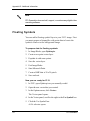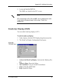
1
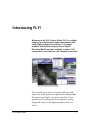
FLY!
User’s Guide
Version 9.0
May 2003
50 West Wilmot Street
Richmond Hill, Ontario, Canada L4B 1M5
Phone: (905) 764-0614
Fax:
(905) 764-9604
E-mail: [email protected]
© 2003 PCI Geomatics Enterprises Inc.®. All rights reserved.
COPYRIGHT NOTICE
Software copyrighted (c) by PCI Geomatics, 50 West Wilmot St., Richmond Hill, Ontario, CANADA L4B 1M5
Telephone number: (905) 764-0614
RESTRICTED RIGHTS
Canadian Government
Use, duplication, or disclosure is subject to restrictions as set forth in DSS 9400-18 “General Conditions - Short Form - Licensed
Software”.
U.S. Government
Use, duplication, or disclosure is subject to restrictions as set forth in FAR clause 52.227-19 “Commercial Computer Software Restricted Rights” and in subparagraph (c) (1) (ii) of the “Rights in Technical Data and Computer Software Clause” at DFARS 52.2277013.
ACE, ACE & Design (logo), ACE Advanced Cartographic Environment, AGROMA, EASI/PACE, EOScape, FLY!, GCPWorks,
GeoAnalyst, GeoGateway, ImageWorks, OrthoEngine, PCI OrthoEngine, PCI, PCI & Logo, Committed to GeoIntelligence Solutions,
PCI Author, PCI Visual Modeler, RADARSOFT, RasterWorks, and SPANS are registered trademarks of PCI Geomatics Enterprises Inc.
PCI Geomatics and Geomatica are registered trademarks of PCI Geomatics Enterprises Inc.
InstallShield is a registered trademark of InstallShield Software Corporation.
Microsoft is a registered trademark, and Windows is a trademark of Microsoft Corporation.
MrSID is a registered trademark of LizardTech Inc. Copyright 1995-2003 LizardTech, Inc. All rights reserved.
UNIX is a registered trademark of The Open Group.
Copyright (c) 2002, Mapping Science, Inc. GeoJP2™ is a trademark of Mapping Science, Inc. The GeoJP2™ format is the intellectual
property of Mapping Science, Inc.
All other trademarks and registered trademarks are the property of their respective owners.
Table of Contents
Introducing FLY!
How to Use this Manual .................................................................... 2
What you can do with FLY! ............................................................... 3
Chapter 1
Getting Familiar with FLY!
Using the Main Panel........................................................................ 5
Managing Vector Layers ................................................................. 14
Defining Raw Database Files.......................................................... 17
Creating a Flight Path ..................................................................... 19
Chapter 2
Flying Through the Terrain
Controlling Flight in the Rendering Window .................................... 26
Editing Rendered Images ............................................................... 31
Checking Performance on Your System ......................................... 39
Chapter 3
Running a FLY! Demo
Opening FLY!.................................................................................. 41
Loading the Terrain......................................................................... 42
Controlling Your Flight .................................................................... 47
Flying Through Your Terrain ........................................................... 49
Creating a Flight Path ..................................................................... 51
Generating a Movie Loop................................................................ 54
Appendix A
Using FLY! from the Command Line
Using Command-line Switches ....................................................... 57
Appendix B
Additional Information
Memory Usage and Speed Hints .................................................... 61
Motif Customization ........................................................................ 61
High Background Value .................................................................. 63
Converting Image Files to Digital Video .......................................... 63
Floating Symbols ............................................................................ 64
Heads-Up Display (HUD) ................................................................ 65
Vector Display................................................................................. 66
i
Table of Contents
Index .................................................................................... 67
ii
PCI Geomatics
Introducing FLY!
Welcome to the FLY! User’s Guide. FLY! is a digital
imaging tool that shows imagery and terrain data
using digital graphic technology. FLY! drapes
airphoto and satellite imagery over a Digital
Elevation Model and then instantly creates a 3-D
perspective scene that you can navigate in real time
You can alter your speed, elevation, and view and
adjust any of the perspective parameters during flight.
To control your flight - just point and click. Create
stationary hover perspectives or program a custom
flight path with several flight parameters that you
select.
FLY! User’s Guide
1
Introducing FLY!
You can overlay vector data to enhance the simulation. Identify
key areas, isolate specific structures, add lines of sight, show
electrical power corridors, railways, place names, and much
more. You can even simulate adverse weather conditions with
the FLY! fogging feature.
In addition to interactive flight you can predetermine a flight
path ahead of time. Select the precise points that make up your
custom flight plan using the nadir image as your guide. Save
your image files in a variety of formats or export them for
conversion to video file formats.
How to Use this Manual
This FLY! User’s guide is divided into four chapters:
Introduction: introduces the features of the software and has
a few suggestions for using FLY! in your work. Built-in
flexibility allows you to use your own creativity for discovering
new uses. Use this chapter to review the features of FLY!.
Chapter 1: contains preliminary instructions and references to
help you become familiar with the main software components.
Refer to this chapter for details about what you can do and how
to set up files with the FLY! Graphical User Interface.
Chapter 2: provides details about managing vector layers and
using the various components of the software to customize your
FLY! session to suit your needs. Use this chapter to learn how
to customize your setup and to control your flight in real time.
Chapter 3: reviews the main functions of FLY! using the
demo files provided on the CD-ROM. It is intended to get you
up and running quickly. Follow the steps carefully and you’ll
be a FLY! expert in no time.
2
PCI Geomatics
What you can do with FLY!
You can review Chapters 1, 2, and 3 or go directly to the demo
in Chapter 4 for a quick start.
For supplementary information about running FLY! from the
command line under both Windows and Unix turn to the
appendixes at the back of this guide.
What you can do with FLY!
Because FLY! uses PCI Geomatics’ GeoGateway technology,
it supports direct data loading from dozens of file types and
GIS/CAD/Map formats.
FLY! is the ideal tool for applications where terrain exploration
is essential:
•
Mission planning
•
Mission rehearsal
•
Non-intrusive reconnaissance
•
Visual Environmental Assessment
•
Determination of geological structure
•
DEM quality assessment
•
Public and Management presentations
FLY! is available for Windows, Unix, and Linux operating
systems.
With FLY! you can:
•
Create a terrain using elevation data and color information
from an image database file.
•
Specify a directional light source through shaded relief.
FLY! User’s Guide
3
Introducing FLY!
4
•
Save terrain renderings to an image file on disk in a variety of
formats. Rendered scenes can be imported or printed by other
software packages.
•
Produce a true vector overlay. All GeoGateway vector
formats are supported.
•
Create a flight path composed of several user-specified nodes
selected from the nadir image.
•
Store the position, direction, and speed parameters in addition
to pitch, view cone, and zoom levels for each node in a flight
path.
•
Play back your flight with VCR type controls, or set FLY! for
continuous playback with a single mouse click.
PCI Geomatics
C
Getting Familiar with FLY!
H A P T E R
1
This chapter introduces you to the FLY! Graphical
User Interface and gives details about the many
features and functions of FLY!
Using the Main Panel
The main panel is the central control for all of the FLY!
features and settings. It has a menu bar with four menus,
four function commands, and a message area.
Figure 1.1 on page 6 shows the Control panel and the
names of the control commands. The command areas
are listed below with a brief description of what they do.
FLY! User’s Guide
5
Using the Main Panel
Figure 1.1
The FLY!
Control Panel
F
D
A
B
C
E
A. Control Panel command B. User Free Flight command
C. Nadir View command D. Flight Path Editing command
E. Message area F. Menu bar.
A Opens the Control Panel to provide a graphical interface.
Use the Control panel to change your position, direction and
speed characteristics.
B Puts FLY! into controlled free flight. You control the flight
interactively while moving through your terrain.
C Opens the Nadir panel to provide an overhead view of the
terrain. Use the Nadir panel to create a flight plan.
D Opens the Flight Editing Panel to create and play flight plan
movies.
E Message area to display brief messages and to show progress
of some actions. Descriptive text appears when your mouse
passes over a function command.
F Menu bar with four menus File, Edit, Options, and Help. The
menu commands are explained below.
Loading Elevation and Color Data
FLY! generates terrains using elevation data and color
information that you choose from an image database file. Use
6
PCI Geomatics
Chapter 1 - Getting Familiar with FLY!
the File menu to access the functions that load DEM and color
datasets.
Figure 1.2
The FLY! File
menu
Full color terrains require three color channels, one each for
red, green, and blue. To create full color terrains select the Load
DEM + RGB command from the File menu.
Monochrome terrains require one color channel to specify
brightness. To create black and white terrains select the Load
DEM + BW option from the File menu.
8-bit pseudo color terrains require one color channel. The Load
DEM + Pseudo Color option is used with 8-bit color imagery
such as 8-bit TIFF, BMP and SPANS files. The color
information is automatically loaded with the imagery data. To
create a pseudo color terrain, select the Load DEM + Pseudo
color option from the File menu.
The Load DEM Shade RGB and the Load DEM shade BW
commands create images that show sunlight throughout the
terrain using a technique known as shaded relief.
FLY! User’s Guide
7
Using the Main Panel
Each of the Load file commands opens a different panel with
more controls for loading and creating specific terrains. Figure
1.3 shows the Load Elevation and Color panel.
Figure 1.3
Load Elevation
and Color panel
All FLY! data files are loaded through panels similar to the
Load Elevation and Color panel shown above. Below is an
explanation of the key parts of the FLY! panels and the
windows that open from the panels.
8
PCI Geomatics
Chapter 1 - Getting Familiar with FLY!
Loading Elevation Data
The Select Elevation File command on the Load Elevation and
Color Panel opens the Database File Selection window. When
you choose a database file the Database Channels window
opens. Elevation and color channels are listed together in this
window.
Figure 1.4
Database
Channels
Window
To load an elevation channel:
•
Choose the elevation data from the list and click Select.
If a file has not been selected, a file selection panel is
displayed prompting you to select a file.
You can reduce the effect of sharp changes in the elevation
model with the Elevation Smoothing option.
•
In the Elevation Information section of the Load Elevation
and Color panel, select one of the following from the
Elevation Smoothing menu. The list below shows how each
elevation option effects the elevation model.
None
FLY! User’s Guide
no smoothing performed
9
Using the Main Panel
Slight
5 x 5 Gaussian filter with
standard deviation 2
Medium
5 x 5 Gaussian filter with
standard deviation 3
Extreme
5 x 5 Gaussian filter with
standard deviation 4
Loading Color Information
The Select Color File command on the Load Elevation and
Color panel opens the Database Channels window for selecting
color channels. Color channel data appears in the same list as
elevation data.
Figure 1.5
Database
Channels
window
When you select a color channel, the values appear in the boxes
below the database channels list. If you have not selected an
elevation or color file, a file selection panel opens to choose an
image database file.
For 24-bit RGB and 8-bit black and white data, you can specify
a color enhancement for each color channel in the terrain with
the Load Elevation and Color panel.
10
PCI Geomatics
Chapter 1 - Getting Familiar with FLY!
In the Color Enhancement list, select:
•
Linear for linear enhancement
•
Root for square root enhancement
•
Equalize for histogram equalization
Adjusting Database Information
The Load Elevation and Color panel has four image
adjustments:
•
Pixel Size to specify the size for each pixel relative to the
ground. Database pixels are square and are measured in
square meters. The default value is 1.00 meter. For PCIDSK
files, pixel size values will be read and filled in automatically.
•
Pixel Height specifies the height of one elevation unit. For
example, if the digital elevation model value is 1,000 and the
pixel height is 1.00 meter. then the real elevation is calculated
at 1000 m. Similarly, if the pixel height is 10 m, the real
elevation is 10,000 m. The default value is 1.00 meter.
•
Terrain X Size determines the size of the terrain. The
elevation data region can be a different size and ratio from the
created terrain. The data is scaled up or down accordingly.
This field is automatically updated to the size of the elevation
data. It can be overridden manually.
•
Terrain Y Size determines the size of the terrain. The
elevation data region can be a different size and ratio from the
created terrain. The data is scaled up or down accordingly.
This field is automatically updated to the size of the elevation
data. It can be overridden manually.
Selecting Data Channels
In the Database Channel selection window, select one or more
color channels to define your terrain. The database channels
FLY! User’s Guide
11
Using the Main Panel
appear in the list with a description of the source, data type, and
a description for the file.
To select an image channel:
1. Click on the desired channel
2. Click the Select command.
3. To close the Database channels window and save your
selection, click the Select and Close command.
Below the list is a caption showing the type of channel you are
selecting. Next to the caption is a blank text field for database
channel numbers. When a text field contains a number, it
indicates that the corresponding channel number is being used
for information.
There are Clear and Default commands beneath the captions
and text fields.
•
Click the Clear command to erase the field.
•
Click the Default command to enter a default channel.
Along the bottom of the panel are a series of action commands.
•
Select & Close selects the channels currently highlighted in
the main loading panel and opens the channel selection panel.
To select a different file from the current one:
•
Click the New File command.
Loading Terrain from Elevation Only
Both the Load DEM Shade RGB and the Load DEM Shade BW
commands in the File menu create terrains using elevation data
only. Each selection opens a corresponding panel. Either the
Load Elevation and Shade in full Color or the Shade as Grey
Levels panel appear depending on the command you selected.
12
PCI Geomatics
Chapter 1 - Getting Familiar with FLY!
All load panels have similar functions. Figure 1.6 shows the
Load Elevation and Shade in Full Color Panel.
Figure 1.6
Load Elevation
and Shade in
Full Color panel
To load an Elevation file:
1. Click the Select Elevation command.
2. Select an elevation channel from the Database Channels
Window.
FLY! specifies a directional light source and computes the
brightness for each pixel in the imagery using a technique
known as shaded relief.
You can adjust the inclination and direction of sunlight using
the slide controls in the Sun Position to Shaded Relief section
of the panel. The Sun Position for Shaded Relief section
specifies the position of the sun relative to the terrain.
•
FLY! User’s Guide
Inclination sets the angle of sunlight.
13
Managing Vector Layers
•
Direction determines the overhead position that the sun
shines from.
The Default command sets a default value of 45 degrees for
inclination and 0 degrees for direction. The None command
places the sun directly overhead at 90 degrees inclination and 0
degrees for direction.
After you have selected the inclination and direction you can
load the channels to render your terrain.
To load your terrain:
•
Click Load in the lower-left corner of the panel.
The Rendering Window displays the terrain with a light
source showing the angle of sunlight in the rendered
terrain.
Managing Vector Layers
When DEM and color files are loaded, you can add new vector
layers to show additional georeferenced information such as
highways, or hydrological information. Each vector creates a
new layer in memory, placing it at a higher level than previous
vector layers.
To load a vector layer:
1. Select Load Vectors from the File menu on the main panel or
click Vectors in the Options menu.
The Database Vector Segments window opens.
14
PCI Geomatics
Chapter 1 - Getting Familiar with FLY!
Figure 1.7
The Database
Vector
Segments
window
2. Select a layer from the list of vector segments.
3. Click Load.
The vector segment loads and the load panel remains
visible.
To load the vector segment and close the panel:
•
Click Load And Close.
To select a new database:
•
Click New File.
When vector files have been loaded, they are controlled using
the Vectors panel.
To open the Vectors panel:
•
Select Vectors from the Options menu.
The Vectors window opens showing a list of Vector files
you loaded through the Options window.
FLY! User’s Guide
15
Managing Vector Layers
Figure 1.8
The Vectors
panel
Note
Very large vector files may take more memory than your system
has available. For very large vector layers use the Compact
Vectors preference to reduce the amount of memory used by a
vector layer.
Each list vector entry shows the name and description
associated with the vector layer, and the number of objects and
vertices in the layer. The Color column shows the current color
of the vector layer. To change the color used to draw the vector
layer, click the color box in the table. A color selection panel
opens.
A checkmark in the Visible column indicates whether the
vector layer is being drawn. Clicking on the Visible box for a
layer to turn drawing on or off.
To disable vector drawing, select the Disable Drawing check
box below the vector table. To enable vector drawing clear the
Disable Drawing check box.
16
PCI Geomatics
Chapter 1 - Getting Familiar with FLY!
To delete a vector layer:
1. Locate the row you wish to delete in the table.
2. Select it by clicking anywhere on the row.
3. Click Delete.
The vector layer is removed from memory only. The layer file
remains in the original file folder.
A vector with higher priority is drawn on top of vectors of lower
priority. By default, priority is determined by the order the
vector layers are loaded. The priority can be changed using the
up and down Priority commands in the lower left of the Vectors
Panel. To move the currently selected vector layer one position
higher in the list, click the Up command. To move the currently
selected layer down one position in the list, click the Down
command.
Defining Raw Database Files
A database that has no georeference information is referred to
as a raw data file. You must define raw files in the Raw
Imagery File Definition Information panel. When you select a
raw file from the Database File Selection window, it is read by
the FLY! software and a selection box opens on the screen.
Figure 1.9
Raw file
definition
warning
To format the raw data file:
•
FLY! User’s Guide
Click Yes.
17
Defining Raw Database Files
The Raw Imagery File Definition Information panel opens.
Figure 1.10
Raw Imagery
File Definition
Information
dialogue box
The Header Bytes field specifies how many bytes at the
beginning of the file represent header information. The default
value is 0, indicating that the imagery data starts at the
beginning of the file.
The Channels field indicates the number of channels or planes
of image data that are stored in the file. The default value is 1.
The Pixels and Lines fields define the size of the image in the
raw file as X, in pixels, and Y, in lines. These fields show the
full size of the image in the file.
The Data Interleaving menu indicates how multiple channels of
image data are interleaved. This field is not applicable for
single channel image files. The Data Type field defines the size
and type of the data for each pixel.
Enhancing Color
In the Load Elevation and Color, the Load Elevation and Grey
Level, and the Load Elevation and Shade in Full Color panels,
a color enhancement can be specified for each channel of the
terrain. From the Color Enhancement menu in the Color
Information section, choose Linear for linear enhancement,
18
PCI Geomatics
Chapter 1 - Getting Familiar with FLY!
Root for square root enhancement, or Equalize for histogram
equalization.
Creating a Flight Path
Flight paths are created in the Nadir window, and saved as a
series of still image files to your local hard drive. The flight
path graphics are displayed using the same elevation and color
characteristics as the image in the rendering window.
A flight path requires two or more nodes. Nodes store the
position, direction, and speed characteristics along with the
pitch, field of view, and zoom levels.
The path is generated along a series of nodes. After you select
the nodes, the rendered graphic files travel along the nodes. The
viewer passes through each node in the direction it was
recorded.
The path is shown as a bezier spline connecting the nodes on the
terrain in the Nadir window. Figure 1.11 shows an exaggerated
illustration of a flight path generated from a series of nodes.
The numbered squares represent the nodes in Nadir window.
Note
Figure 1.11 is exaggerated for clarity. Your nodes and flight path
will appear smaller in your Nadir window.
FLY! User’s Guide
19
Creating a Flight Path
Figure 1.11
Nadir Window
showing a flight
path composed
of 5 nodes
Selecting Nodes for Your Flight Path
Together, the Flight Panel and Nadir window build your flight
path. To open the Flight panel, click the Flight Path Editing
command on the main panel.
20
PCI Geomatics
Chapter 1 - Getting Familiar with FLY!
Figure 1.12
Flight Path
Editing
command
The FLY! Flight Panel opens.
Figure 1.13
Flight panel
showing
coordinates
and elevations
for 5 nodes in
the flight path
The total path length appears at the top of the panel. The length
of the path increases with additional nodes.The window below
the total path length displays a list showing the coordinates and
the elevation of the current nodes.
The first number, beginning at the left of the listing, is the
chronological node number. The second and third numbers, in
brackets, are the x and y screen coordinates. Both of these
values are expressed in pixels. The fourth and final number is
the node elevation.
FLY! User’s Guide
21
Creating a Flight Path
You can edit nodes with the commands below the list window.
The following list shows the name of each command and a
description of what it does.
Clear removes the entire list of nodes from the window.
Update changes the selected node to the current rendering
characteristics.
Insert changes the order of a node in the list by inserting it
behind the current node and shifting other node entries down
one level.
Add places a node, selected in the Nadir window, at the end of
the current list. A newly added node is highlighted.
Delete removes a highlighted node from the list.
Generating a Flight Path Movie Loop
Warning
Be sure you have adequate disk space before recording flight path
files. Flight path files require large amounts of disk space. For
example, the rendered flight path illustrated in Figure 1.11 is
approximately 400 MB. To make a smaller file, use fewer nodes or
place your nodes closer together for a shorter overall flight path.
After you have selected the nodes for your flight path movie,
you can generate your movie loop. To generate your movie,
click on the Generated Movie Loop command in the lowermiddle of the Flight panel.
Video playback is controlled by clicking on the VCR-type
controls above the Generate Movie Loop command.
22
PCI Geomatics
Chapter 1 - Getting Familiar with FLY!
Flight playback occurs from the current position along the path.
Selecting a node in the list will change the path position. During
playback, all of the conventional methods of control are
disabled and the flight panel cannot be closed. The continuous
playback mode repeats playback until you click the stop
command. To stop continuous playback, click the Continuous
Playback command in the lower-right of the panel.
Saving Your Flight Path Movie
FLY! creates a movie as a series of individual images or frames
and assigns consecutive file names to each image file. For
example, if TIFF format is chosen, using the base file name
FLY!, the files are assigned names in the following order:
1. FLY!00000.tif
2. FLY!00001.tif
3. FLY!00002.tif
and so on to the last file in the flight path. There are six image
file formats to choose from.
•
TIFF
•
TARGA
•
BMP
•
PPM
•
JPEG
•
Parallax movie format
Note
You must convert files to a video format to retrieve them and play
them back. FLY! cannot save, reload, and replay digital video files.
A separate software product is required to convert the image files
into a digital video format such as QuickTime, AVI, or MPEG. For
FLY! User’s Guide
23
Creating a Flight Path
more information see “Converting Image Files to Digital Video” on
page 63.
Select the format you wish to use from the File Format menu on
the Movie Loop Frame Generation panel. Figure 1.14 shows the
File Format menu.
Figure 1.14
Movie Loop
panel showing
the File Format
list.
Saving your Flight Path as a 3-D Image
FLY! can save your flight path movie in a 3-D format. Select
Parallax Movie Format from the File Format drop down menu
on the Movie Loop panel. FLY! renders movie files in 3-D
format. To view your movie in 3-D, you’ll need a pair of 3-D
glasses.
24
PCI Geomatics
C
Flying Through the Terrain
H A P T E R
2
After you load your terrain you are ready to fly
through your flight path. The User Free Flight
function is accessed by clicking the User Free Flight
command on the main panel.
Figure 2.1
User Free Flight
command
In free flight mode, the viewer moves forward until you
make an adjustment with the controls. All navigational
and rendering controls are active. The flight can be
started or stopped at any point in the rendered terrain by
clicking the User Free Flight command again. Use your
mouse to control flight characteristics in both the Nadir
Window and the Rendering Window.
FLY! User’s Guide
25
Controlling Flight in the Rendering Window
Controlling Flight in the Rendering Window
You can fly through the terrain in the Rendering Window,
controlling your flight using your mouse buttons to turn, pause,
run, and change elevation.
To turn, changing the direction of view and movement, click on
the Rendering Window in the direction you wish to go.
To toggle between pause and run, hold the CTRL key and click
your left mouse button. With a three-button mouse, press the
middle button.
For a higher elevation, right-click in the upper part of the
window. For a lower elevation, right-click in the lower part of
the window.
Figure 2.2
FLY! Rendering
Window with
loaded Terrain
26
PCI Geomatics
Chapter 2 - Flying Through the Terrain
Using the FLY! Control Panel
The FLY! Control panel has five areas that set and report
characteristics for position, direction, elevation, and speed
Figure 2.3
The FLY!
Control panel
A
B
D
C
E
A. Position Indicator B. Direction Control C. View Control
D. Elevation Slide Control E. Speed Slide Control
There are four controls available in the FLY! Control panel:
•
Position shows your location in the terrain. The corners of the
window correspond to the corners of the Render window. To
change the view in the Render window, click anywhere inside
the Position Window. The Render window view changes
relative to where you have clicked in the Position window.
•
Direction changes the direction of movement and the
direction the viewer is facing. The direction of movement and
the view can be different. The long black line changes
direction and the short red line changes the view. To change
the direction and view together, click inside the circle
indicator. To change the view only, right-click inside the
circle indicator.
•
Elevation slide control changes the elevation of the view in
the Rendering window. To adjust the range of elevation
values use the Options menu on the main panel.
•
Speed slide control changes the file reading rate of the
Rendering window. To adjusted the range for this control use
the Options menu on the main panel.
FLY! User’s Guide
27
Controlling Flight in the Rendering Window
Controlling Flight in the Nadir Window
The Nadir window shows the overhead or nadir view of the
terrain. To open the Nadir window click on the Nadir View
command on the main pane
Figure 2.4
Nadir View
command
Figure 2.5
FLY! Nadir
window
A B
C
A. Color Options command, B. Zoom Image Controls,
C. Show Elevation/Show Imagery toggle command.
28
PCI Geomatics
Chapter 2 - Flying Through the Terrain
The default size of the Nadir window is 512 pixels by 512 lines.
Window dimensions vary to maintain a 1:1 aspect ratio
according to the data files FLY! is using.
A black and white marker indicates the current position and
direction of movement on the terrain. The white part of the
marker is a cross shape indicating the current movement
direction.
To place the viewer at a location on the terrain, click on the
terrain in the desired position. To change the direction and view
together, right-click near the position marker in the desired
view. The view and direction change to the position of the click.
With a three-button mouse the middle-click changes only the
viewing direction.
Using the Nadir Window Controls
There are three sets of controls at the top of the Nadir window.
The Options command, the zoom image controls, and the Show
Elevation/Show Image command.
The options command opens a panel to set color and path
options for the Nadir window. To open the Nadir Options panel
click the Options command on the Nadir window
Figure 2.6
Nadir Color
Options panel
FLY! User’s Guide
29
Controlling Flight in the Rendering Window
Selecting Color Options
Below is a list of options commands in the Nadir Options panel:
•
Show Path shows the flight path in the nadir view.
•
Show Node Numbering displays each node in the path with
its node number. When your flight path numbering clutters
the nadir view set Show Node Numbering to off.
•
Path Color Edit command opens the Path Color Editing
panel. To change the flight path color, click the Edit
command to the right of the Path Color title. The Path Color
Editing window opens.
Figure 2.7
Path Color Edit
window
Adjust Red, Green, and Blue color values using the slider or by
typing a value directly into the corresponding text box.
•
Highlight Color changes the color of the nodes in the Nadir
window.
To adjust the node color, click the Edit command to the right of
the Highlight Color title. The Highlight Color Editing window
opens.
Adjust Red, Green, and Blue color values using the slider or by
typing a value directly into the corresponding text box.
•
30
Path Resolution changes the total number of line segments
used to draw the path.
PCI Geomatics
Chapter 2 - Flying Through the Terrain
•
Path Resolution changes the resolution of your flight path in
the Nadir window.
To change the path resolution, click an arrow on the box to the
right of the Path Resolution title or type a value directly into the
text box. A higher number makes the path look smoother
because more lines are used to draw curves in the flight path.
•
The Nadir window can show either rendered terrain images or
unprocessed elevation images. To display either the rendered
image or the elevation image, click the Show Elevation/Show
Imagery command at the top of the Nadir window.
Editing Rendered Images
The Edit menu has four commands that open dialog boxes for
editing your rendering characteristics. Figure 2.8 shows the
Edit command list.
Figure 2.8
Edit command
list
Changing Position, Speed, and Direction
The Position, Speed, Direction option in the Edit menu opens
the panel shown in Figure 2.9 on page 32. You can modify the
viewing position, the speed, and the direction of movement.
FLY! User’s Guide
31
Editing Rendered Images
Figure 2.9
Position,
Speed,
Direction, panel
You can enter explicit values for the viewer position, direction,
and speed. These characteristics can also be set with the Control
panel when exact positioning is required.
Resizing the Rendering Window
The Rendering Size option in the Edit menu specifies the size
of the rendering window in pixels and lines.
Figure 2.10
Render
Window panel
To adjust the width of the frame in pixels, click the Frame X
Size field. Type the number of pixels at the cursor. To adjust the
height of the frame in lines, click the Frame Y Size field. Type
the number of lines in the Frame Y Size field. Common sizes
for rendering windows are 320 x 240, or 640 x 480. The
minimum is 64 x 64. The maximum is 1024 x 768.
32
PCI Geomatics
Chapter 2 - Flying Through the Terrain
Adjusting the Rendered Image Perspective
Use the Perspective dialog box to change the perspective
characteristics of the rendered image.
Figure 2.11
Perspective
dialogue box
Height Magnification exaggerates the elevation. The default
setting is 1.0. Values can vary from 0 to 3.0. A value of 0
removes elevation completely.
Horizon Tilt changes the horizon position by degrees. Values
can vary from 0 to 60. The default setting is 25 degrees.
Pixel Zoom controls the size of foreground pixels at low
elevations. Settings vary from 0.01 (1%) to 1.00 (100%). The
default is 1.00. The maximum size of foreground pixels is
automatically determined by FLY!.
Field of View changes the view cone in the rendered image.
The default setting is 60 degrees. A larger field of view value
exaggerates the perspective in the render window.
Changing 3-D Characteristics
You can modify the characteristics that control 3-D viewing in
the 3-D Edit command. Alter the values in this dialogue box to
enhance 3-D effects.
FLY! User’s Guide
33
Editing Rendered Images
Figure 2.12
3-D dialogue
box
Focal Length specifies the focusing point in pixels. Values
vary from 32 to 512 pixels. The default setting is 64 pixels.
Base Line changes the interval between left and right images
from 1 to 30 pixels. The default setting is 4 pixels.
Setting Scales and Flight Characteristics
Use the Options menu to change graphical preferences and
qualities, and to adjust the rendering mode.
Figure 2.13
Options Menu
Setting Elevation Options
The Elevation Options panel controls characteristics for
rendered images. To open the Elevation Options panel, select
Elevation Options from the Options menu.
34
PCI Geomatics
Chapter 2 - Flying Through the Terrain
Figure 2.14
Elevation
Options
dialogue box
The Elevation Minimum and Elevation Maximum fields set the
range of values for the elevation slide control on the main
panel. The number entered in the Elevation Maximum field
must always be higher than the number entered in the Elevation
Minimum field.
The Scaling option sets the type of scale for elevations. A
square scale measures elevation proportional to the square of
the slide value.
Selecting an Elevation Mode
You can change the way your flight position is displayed in the
Rendering window during flight with the Mode menu.
No Collision mode never shows the rendered image below the
land elevation. FLY! automatically adjusts the terrain keeping
the view above the surface. The land elevation is shown on the
Control Panel.
Relative mode shows the land elevation and the elevation scale
value.
Absolute mode scales the elevation directly as the rendering
height. When the elevation view drops below the terrain the
rendered image appears as vertical strips because the view is
lower than the terrain. To regain a view above the terrain
FLY! User’s Guide
35
Editing Rendered Images
increase the value in the elevation Minimum field on the
Elevations Option panel.
Setting Speed Options
The Speed Options panel controls settings for viewer speed.
Figure 2.15
Speed Options
dialogue box
The Speed Maximum field determines the range of speed
values used by the Speed slide control on the FLY! Control
panel.
The Scaling field changes the type of scale used to determine
the speed of the viewer. A square scale gives a speed value
proportional to the square of the value on the Speed slide
control.
Selecting a Coordinate System
You can change the coordinate system used for reporting the
viewer position on the terrain with the Coordinates commands
in the Options menu.
36
PCI Geomatics
Chapter 2 - Flying Through the Terrain
Figure 2.16
Options menu
showing the
Coordinates
commands
Display reports your position in pixels and lines in the loaded
terrain.
Geocoded reports your position in geocoded units as eastings
and northings.
Geographic reports your position in geographic units as
latitude and longitude.
Changing Units of Measure
Change the unit of measure for distance and speed with the
Units item in the Options Menu.
Metric measures distance in meters and speed in kilometers per
hour.
Imperial measures distance in feet and speed in miles per hour.
Selecting the Rendering Quality
Use the Rendering Quality submenu to adjust the quality of
your rendered image.
FLY! User’s Guide
37
Editing Rendered Images
Figure 2.17
Options Menu
showing
Rendering
Quality
commands
There are three quality options to choose from:
•
Blocky/Fast displays an image with pixels as boxes with
pronounced steps between each block. Blocky/Fast is the
default, and fastest, rendering mode.
•
Fitted/Medium interpolates pixels so they fit together
without any step effects in the displayed image.
•
Smooth/Slow interpolates the edges of the pixels so they fit
together without any step effects and the colors of the pixels
are blended.
Choosing a Rendering Mode
There are two rendering modes to choose from in the Options
menu. Use the Normal rendering mode for a typical rendered
image.
38
PCI Geomatics
Chapter 2 - Flying Through the Terrain
Figure 2.18
Options menu
showing the
Render Mode
submenu
For a stereo image, use the Anaglyph 3D option. This is a
special mode of rendering where the left view is rendered in red
and the right view in blue. The two-colored views are combined
to create a three-dimensional image. Anaglyph glasses with red
and blue tinted lenses are required to view these images with a
three-dimensional effect.
Note
Two more rendering modes are available on SGI workstations.
Stereo Glasses mode renders a color stereo image for the entire
screen. Special liquid crystal stereo glasses are required to view
the rendered image. Stereo Glasses Expanded mode expands the
vertical and horizontal size to produce an image 4 times larger
than Stereo Glasses mode. To start or stop flight press the space
bar. Pressing any other key will return you to normal mode.
Checking Performance on Your System
The Frames Per Second command in the Options menu opens a
panel showing a number of benchmarks for evaluating FLY!’s
performance on your system. The benchmarks are based on the
last ten views generated in the rendering window.
FLY! User’s Guide
39
Checking Performance on Your System
To test FLY!’s performance, you must use the User Free Flight
feature. To open the Benchmarks panel, click the Options menu
then click Frames Per Second.The Benchmarks panel opens.
You can check the information in the Benchmarks panel.
Figure 2.19
Benchmarks
panel
40
PCI Geomatics
C
H A P T E R
Running a FLY! Demo
3
This chapter contains a step by step guide to
loading and running one of the demonstration files
that comes with your FLY! software. The FLY! CD
contains a demo file folder with all the data you will
need to generate a three dimensional terrain, create
and view a flight plan, and use all the features and
functions in the FLY! software.
In this chapter you will learn how to:
•
Open the FLY! application.
•
Load your terrain by selecting color and elevation
channels.
•
Control free flight with the FLY! Control Panel.
•
Fly through the terrain in the Rendering Window.
•
Create a flight plan in the Nadir Window.
•
Generate and Control a Movie loop from data you
select.
Opening FLY!
To open FLY!, click the FLY! command in the
Geomatica toolbar, or click the FLY! command from
the programs list in the Start menu.
FLY! User’s Guide
41
Loading the Terrain
Figure 3.1
The Geomatica
FLY! command
The main panel and the Render window appear on your
desktop. Figure 3.2 shows the FLY! main panel with the Render
window. No files have been loaded so the function commands
are unavailable and the render window is empty.
Figure 3.2
FLY! Main
Panel and
Rendering
Window before
files are loaded.
Loading the Terrain
You must load a Digital Elevation Model (DEM) file and, either
a color channel file, or a black and white shading file for each
FLY! session to generate a motion graphic. Load both the DEM
and Color data from the File drop down menu on the main
panel.
To load a FLY! terrain:
1. Click the File menu on the main panel
2. Click the Load DEM + RGB command in the File menu.
42
PCI Geomatics
Chapter 3 - Running a FLY! Demo
Figure 3.3
FILE menu
The Load Elevation and Color panel opens.
Figure 3.4
Load Elevation
and Color
Panel
3. On the Load Elevation and Color Panel, click the Select Elevation
File command at the top of the panel.
FLY! User’s Guide
43
Loading the Terrain
The Database File Selection window opens showing a list
of the file folders in the geomatica_v90 directory.
Figure 3.5
Database File
Selection
Window
showing demo
folder
4. Double-click the demo folder.
The file window shows the demo database files.
Figure 3.6
Database File
Selection
Window
showing flydata
database file
5. For this demonstration, click on the flydata file
6. Click the Open command.
44
PCI Geomatics
Chapter 3 - Running a FLY! Demo
The Database Channels window opens with a list of
elevation and color channels.
Figure 3.7
Database
Channels
Window with an
elevation
channel
highlighted
7. Click in the list on the 5 [16s]: USGS Elevation Data (1 metre
interval) database.
8. Click the Select command.
The elevation data is now ready to load. Next, you will load
color channels from the same Database Channels window. You
may need to move the Database Channels window out of the
way to access the Load Elevation and Color Panel.
To load color channels from the Database Channels
window:
1. Click the Select Color File command on the Load Elevation
and Color panel.
The Database Channels Window is now set for selecting
color data.
FLY! User’s Guide
45
Loading the Terrain
Figure 3.8
Database
Channels
Window with
one color
channel
highlighted
Color channel data can be selected one file at a time from
the list, by highlighting the file and pressing the select
command after each selection. Default values can be
selected by clicking on the Default command below the
file list.
2. For this demonstration, click Default.
Note
FLY! enters default color values in the color value boxes below the
Database Channels list.
3. Click the Select and Close command in the lower right of the
Database Channels Window.
The Window closes and all of the elevation and color data
you have selected is ready to load.
4. Click the Load command in the lower left of the Load
Elevation and Color Panel.
The panel closes and a progress monitor opens displaying
the file loading activity.
46
PCI Geomatics
Chapter 3 - Running a FLY! Demo
When the files have finished loading the progress monitor
closes. The menu and button commands are now available.
The Render Window shows a landscape with a horizon that
FLY! has generated from the data you have loaded.
Figure 3.9
Main Panel
after files are
loaded.
Figure 3.10
Rendering
Window
showing a
rendered
image.
Controlling Your Flight
The function commands on the main panel control different
features of FLY!. When you pass your mouse pointer over a
command button, its function appears in the text box at the
bottom of the main panel.
Control your flight through the terrain with the Parameters
Control Panel.
FLY! User’s Guide
47
Controlling Your Flight
To open the Control panel:
•
Click the Parameters Control command on the main panel.
Figure 3.11
Parameters
Control
command
The control panel opens on your desktop.
Figure 3.12
The FLY!
Control Panel
D
C
B
E
A
A. Position Indicator B. Direction Control C. View Control
D. Elevation Slide Control E. Speed Slide Control
There are four controls available in this panel.
•
Position gives a scaled representation of the terrain in the
square area. Each corner of the square corresponds to a corner
of the terrain displayed in the Render Window. To change the
view in the Render Window, click anywhere within the
Position Window. The Render window view changes relative
to where you have clicked in the Position Window.
Direction changes the direction of movement and the direction
of view. The direction of movement and the view can be
different. The direction of movement is controlled by the long
black line and the view by the shorter red line. To change
48
PCI Geomatics
Chapter 3 - Running a FLY! Demo
direction and view simultaneously, click inside the circle
indicator. To change view only, right-click inside the circle
indicator.
•
Elevation slide control changes the elevation of the view in
the Rendering Window. The range of elevation values can be
adjusted through the Options menu on the main panel.
•
Speed slide control changes the file reading rate of the
Rendering Window. The range for this control is adjusted
through the Options menu. The text information to the right
of the Direction control reports the current position, speed,
and direction.
Flying Through Your Terrain
You are now ready to fly through the terrain in the rendering
window.
To start flying:
•
Click the User Free Flight command on the main panel.
Figure 3.13
User Free
Flight
command
The terrain moves in the direction and speed you select from the
Control Panel. If you have not selected a speed or direction,
FLY! will use default settings.
To stop the flight:
•
Click the User Free Flight command again.
The flight stops at the current position.
FLY! User’s Guide
49
Flying Through Your Terrain
To resume free flight:
•
Click the User Free Flight command again.
Flying from the Nadir Window
FLY! provides an overhead or nadir view of the terrain to help
you fly with added visual accuracy.
To open the Nadir Window:
•
Click the Nadir View command on the main panel.
Figure 3.14
Nadir View
command
The Nadir window opens showing the terrain from above.
Figure 3.15
Nadir Window
showing overhead view of
terrain
50
PCI Geomatics
Chapter 3 - Running a FLY! Demo
Click anywhere inside the Nadir Window.
A position indicator opens, and your current position changes
to where you clicked inside the Nadir window terrain.
To change the position of flight, click anywhere inside the
Nadir Window when User Free Flight function is either on or
off.
To change the direction of flight in the Nadir window, rightclick on the terrain in the direction you wish to fly. The flight
direction changes in the direction of your mouse pointer.
Creating a Flight Path
You can record a flight plan to move in any direction over the
terrain in the Nadir Window using the Flight Path Editing
function. The flight plan is programmable for elevation, speed,
direction, and view.
Next, you will create a flight plan from the terrain in the Nadir
and the Rendering windows. Use the default elevation, speed,
color, and rendering settings to create a simple flight plan.
To create your own flight plan:
1. On the main panel, click the Flight Path Editing command.
Figure 3.16
Flight Path
Editing
command
The Flight Panel opens on your desktop
FLY! User’s Guide
51
Creating a Flight Path
Figure 3.17
FLY! Flight
Panel before
creating nodes
There are several control commands on the Flight Panel
but for now, only the Add, Close, and Help commands are
available.
2. Click anywhere in the Nadir Window.
The position indicator is shown where you clicked in the
image.
3. Below the text window, on the Flight Panel, click Add.
FLY! automatically generates coordinates to produce the
first node in your flight plan and lists them in the Flight
Panel. The remaining editing commands are now available.
You can clear, update, insert and delete coordinate
information as you wish.
To add more nodes to your flight path:
•
52
Simply click in the Nadir window and click the Add
command after each selection. Repeat steps 2 and 3 above
until you have several nodes linked together to form a path.
PCI Geomatics
Chapter 3 - Running a FLY! Demo
Figure 3.18 shows an illustration of a flight path with 5 nodes
that follows a feature of the terrain. You can place your nodes
in a line anywere on your image.
Note
Figure 3.18 has been enhanced for graphical clarity. Your nodes
will look smaller and your flightpath will have thinner lines.
Figure 3.18
Nadir Window
showing
illustration of
flight path
FLY! User’s Guide
53
Generating a Movie Loop
Warning
Be sure you have enough disk space to record a flight path file.
Flight path files require large amounts of disk space. The rendered
Flight Path file shown in this illustration is approximately 400 MB.
Generating a Movie Loop
After you have added all of the nodes for your flight plan, you
can generate a movie loop to fly along your flight path.
To generate a movie loop:
1. In the lower middle of the Flight Panel, click Generate
Movie Loop.
Figure 3.19
FLY! Flight
Panel showing
coordinates for
5 nodes
The Movie Loop Frame Generation dialog box opens.
54
PCI Geomatics
Chapter 3 - Running a FLY! Demo
Figure 3.20
Movie Loop
Frame
Generation
Dialogue Box
You can choose from several file formats in the File
Format menu. For this demonstration, leave the file format
at Sequential BMP frames.
2. In the Frames Per Second setting, use the default value of 15.
3. Enter a path to store your rendered flight plan on your local
hard drive in the Directory for Generated Frames text box
shown by the circled area in Figure 3.20.
4. When the appropriate file path is entered, click the Generate
Frames command in the lower left of the Movie Loop Frame
Generation dialogue box.
Frames may take several minutes to generate. During rendering
the commands on the main panel are not available. An indicator
opens at the bottom of the main panel showing the progress of
the frame generation and the position indicator in the Nadir
Window moves along the flight path.
Figure 3.21
Main Panel
showing
progress
indicator
FLY! User’s Guide
55
Generating a Movie Loop
When FLY! has finished generating the flight path frames, the
main panel commands are available again.
The video play commands, along the lower part of the Flight
panel, control the speed and direction of video replay like
conventional VCR controls. Click the Play, Stop, Fast Forward,
Reverse, and Fast Reverse buttons to change the video replay.
Figure 3.22
VCR controls at
the bottom of
the FLY! Flight
Panel
Now that you know the basics for using FLY!, try a few
adjustments on your own. Refer to “Flying Through the
Terrain” on page 25 for details on tailoring your FLY! sessions
to exactly what you want. You can add fog to your rendered
terrain, adjust and record changes in elevation and texture and
even create and view your flight in 3-D. You can make dozens
of adjustments using the various controls.
56
PCI Geomatics
A
P P E N D I X
A
Using FLY! from the Command Line
Using Command-line Switches
If you wish, you can start and operate FLY! using
command-line switches.
The command string example, below, loads the file
flydata.pix using channels 4, 2 and 3 for red, green and
blue. Channel 5 is used for elevation. A linear
enhancement is performed on the color data and the
elevation is stretched by a factor of 2. At start-up the
viewer is positioned at x = 512, y = 10 with an elevation
of 400. The view direction is 180 degrees. The tilt angle
is 30 degrees.
fly -file flydata.pix -chan 4 2 3 5 linear -heightmag 2 -xy 512 10 -z 400
-dir 180 -tilt 30
The following tables list the commands used to operate
FLY! from a command line prompt.
FLY! User’s Guide
57
Appendix A - Using FLY! from the Command Line
To do this:
Specify the files for color and elevation data.a
Assign elevation or color channels.b
Enter this Command:
-file file
-chan e
-chan grey e
-chan r g b e
58
Assign size of a pixel on the
ground in metres.30 m. (default)
-pixelsize size
Step resolution of elevation data.
- 1.0 meter (default)
-pixelheight size
Set size of output for rendered
frames. 320 by 240 (default)
-frame xsize ysize
Set elevation scaling factor values. from 0.0 to 3.0. 1.0 (default)
-heightmag factor
Set initial position. X, Y values
are in pixels. Upper-left corner
(default)
-xy x y
Set initial height. Z value is in
elevation units of DEM data, 0
(default)
-z z
Set initial viewing direction in
degrees. 180 (default)
-dir direction
Zoom foreground pixels. Valid
values from 0.01 (1%) to 1.00
(100%) - 1.00 (default)
-zoom factor
Tilt (position of horizon) in
degrees from 0 to 60. 25
(default)
-tilt angle
View cone angle for rendered
frames from 0 to 120 degrees. 60
degrees (default)
-frustum angle
Use 3-D anaglyph mode
-3d
Set linear enhancement.
-linear
Set root enhancement
-root
Set equalization enhancement.
-equal
PCI Geomatics
Appendix A - Using FLY! from the Command Line
To do this:
Enter this Command:
Select blocky quality
-blocky
Select fitted quality
-fitted
Select smooth quality
-smooth
Select shade relief direction
-shadedir angle
Set shade relief inclination angle.
-shadeinc angle
Display command line options
-help
Display version number
-version
Open the flight panel.
-flightpanel
Open Nadir window when the
program is started
-nadir
Open control panel when the
program is started.
-control
Load a flight plan.
-flight [filename]
Apply fogging effects.
-fogging
[percentage]
Smooth image. Factors 0 - 3c
-loadsmooth
[factor]
Specify an alternate sky color.
Values between 0 and 255 for
each channel. Where 0 0 0 =
Black
-skycolor [red]
[green] [blue]
a. Named file is any supported GDB file except raw files.
b. Numbers r, g, b, grey and e give channels holding color and
elevation. A single number is assumed as an elevation channel
and is loaded as color shaded relief terrain. Two numbers are
read as 1st - grey intensity and 2nd - elevation. All four channels are specified as red, green, blue and elevation channels.
c. Numbers correspond to the following:
0 - None, No smoothing.
1 - Slight, 5x5 Gaussian Filter with standard deviation 2
2 - Medium, 5x5 Gaussian Filter with standard deviation 3
3 - Extreme, 5x5 Gaussian Filter with standard deviation 4
FLY! User’s Guide
59
Appendix A - Using FLY! from the Command Line
60
PCI Geomatics
A
P P E N D I X
Additional Information
B
Memory Usage and Speed Hints
FLY! is a memory intensive application. The following
chart shows the RAM memory required for various
input data sizes:
1024 x 1024
7 Mbytes
1536 x 1536
14 Mbytes
2048 x 2048
24 Mbytes
4096 x 4096
88 Mbytes
Add 5 to 8 MB on top of this for the operating system
and user interface. To achieve maximum performance,
it is best not to run any other applications while FLY! is
active.
Motif Customization
Customizing the appearance of FLY! on X/Motif
systems.
FLY! User’s Guide
61
Appendix B - Additional Information
FLY! resources, such as fonts and colors are customized on
operating systems using X-Windows Motif, through the X
defaults file in the user’s login directory.
The available resources are:
For general purpose font for most applications.
fly*fontList:<font>
(e.g., fixed)
For font used in areas requiring monospaced characters (e.g.
main text in help panel)
fly*fixedFont:<font>
(e.g., 10x20)
For background color for most panels.
fly*background:<color>
(e.g., grey)
For color of all menu bars.
fly*MenuBar*background:<color>
thistle)
(e.g.,
Color for all title bars.
fly*TitleBar*background:<color>
lightsteelblue)
(e.g.,
Available fonts and colors will depend on your system. Under
some environments (such as HP VUE), customization is
handled by means other than the X defaults file. See the
operating system user documentation for these environments.
To set these resources system-wide, you must create an
application default file called fly, with the same format as the X
defaults file. It is typically placed in the directory /usr/lib/X11/
app-defaults.
62
PCI Geomatics
Appendix B - Additional Information
High Background Value
If you are using 16-bit data that has a very high background
value, i.e. -32767, the image may not render properly in the
view. To work around this situation, type the following
command at the command line:
fly -datamap --32767 0
This is also explained in the command line help.
Converting Image Files to Digital Video
You must convert files to a video format to retrieve them and
play them back. FLY! cannot save, reload, and replay image
files as digital video. After you create the individual frames,
using the Generate Movie Loop command, a separate thirdparty software product is required to convert the image files
into digital video format.
Video files, such as QuickTime, AVI, and MPEG, can be
created from the FLY! rendered frames with third-party
encoding software available in some multimedia packages and
as freeware on the Internet.
For example, there are demo versions of MPEG encoders
available on the World Wide Web:
Xing MPEG Encoder
•
http://www.xingtech.com/
VideoStudio, by Ulead
•
FLY! User’s Guide
http://www.ulead.com
63
Appendix B - Additional Information
Note
PCI Geomatics does not sell, support, or endorse any digital video
encoding software.
Floating Symbols
You can add a floating symbol layer to your FLY! image. First
you must prepare a bitmapfile with point data to locate the
symbols relative to the background image.
To prepare data for floating symbols:
1. In ImageWorks, open flydata.pix.
2. Create a new point vector layer.
3. Populate it with some points.
4. Save the vector layer.
5. Exit ImageWorks.
6. Start Microsoft Paint.
7. Create a BMP that is 20 x 20 pixels
8. Save and exit.
Now you are ready for FLY!:
1. In FLY!, open flydata.pix as you normally would.
2. Open the new vector that you created.
3. In the Options menu, click Vectors.
The Vector panel opens.
4. In the Vector panel, scroll to the right to the Use Symbol box.
5. Click the Use Symbol box.
A file selector opens.
64
PCI Geomatics
Appendix B - Additional Information
6. Locate and load the BMP file.
The BMPs are loaded to the FLY viewer.
Note
PCI recommends a 20 x 20 size BMP, as it is displayed as such.
Larger sizes will appear larger in the image. There is no
perspective.
Heads-Up Display (HUD)
You can add a heads-up display to FLY.
To add a heads-up display:
1. Under Options, click the HUD display drop-down menu list.
2. The Heads Up Display Configuration Panel opens.
Figure B.1
The HUD Panel
•
•
•
•
•
Activate the Heads Up Display: Activates the Heads up Display.
Values to Show: Shows the Values.
Text Attributes: Lets you set the Text attributes.
Close: Closes the HUD Panel.
Help: Opens the Helper.
FLY! User’s Guide
65
Appendix B - Additional Information
Vector Display
You can show a vector layer in a FLY! image and set a
customized threshold so that you can only see it when you are
at a specified altitude.
To set this up, there are two new options in the Vector control
panel:
•
•
66
Display above: Sets the lower limit of the threshold.
Display below: Sets the upper limit of the threshold.
PCI Geomatics
Index
Numerics
3-D
changing parameters, 33
A
adjusting
database information, 11
image perspective, 33
B
Background value
high background value, 63
C
changing
units of measure, 37
checking
system performance, 39
choosing
rendering mode, 38
color channels
enhancing, 18
color data
loading, 10
color shaded terrains
selecting, 7
color terrains
loading, 7
controlling
direction, 27
elevation, 27
flight, 26
position, 27
speed, 27
controlling flight
in the nadir window, 28
controls
nadir window, 29
coordinate system
selecting, 36
creating
a flight path, 19
flight path, 19, 38
D
data channels
selecting, 11
database information
adjusting, 11
direction
controlling, 27
E
editing
path color, 30
rendered images, 31
elevation
controlling, 27
smoothing, 9
terrain from only, 12
elevation smoothing, 9
enhancing color
color channels, 18
F
feature
main panel, 5
File
drop-down menu, 6
flight panel
using, the, 21
flight path
creating a, 19
FLY! control panel
using, 27
G
generating
movie files, 22
H
header bytes
specifying for raw file definitions, 18
67
Index
I
O
image
adjusting perspective, 33
options
color, 30
nadir window, 29
path color, 30
setting elevation, 34
setting speed, 36
vector layers, 15
options menu
using, 34
L
light angle
shaded terrain, 13
load elevation and color
in demo folder, 43
loading
color data, 10
color shaded terrains, 13
elevation data, 9
grey scale shaded terrains, 7
terrain from elevation only, 12
vector layers, 16
loading terrain
from elevation only, 12
loading terrains
color, 7
in demo folder, 42
monochrome, 7
M
main panel, 5
using, 5
managing
vector layers, 14
menu
File, 6
monochrome terrains
loading, 7
movie files
generating, 22
playing, 22
saving, 23
MPEG encoders, 63
N
nadir window
color options, 30
controlling flight in, 28
controls, 28
options, 29
nodes
defined, 19
selecting, 20
68
P
parameters
changing 3D, 33
path color
editing, 30
playing
movie files, 23
pseudo color terrains
loading, 7
R
raw file definitions
specifying header bytes, 18
working with, 13
render window
resize, 32
rendered images
editing, 31
rendering mode
choosing, 38
rendering window
controlling flight in, 26
resize, 32
resize
render window, 32
running
FLY! demo, 41
S
saving
movie files, 23
selecting
color shaded terrains, 7
coordinate system, 36
data channels, 11
demo color channel, 46
demo elevation channel, 45
demo file, 44
greayscale shaded terrains, 8
PCI Geomatics
Index
nodes, 21
vector layers, 14
setting
elevation options, 34
rendering quality, 37
speed options, 36
shaded terrain
light angle, 13
smooting
elevation, 9
speed
controlling, 27
setting options, 36
starting
FLY! application, 41
user free flight, 25
system performance
checking, 39
U
units of measure
changing, 37
user free flight
starting, 25
using
database channels window, 9
edit menu, 31
flight panel, 21
FLY control panel, 27
main panel, the, 5
options menu, 34
rendering window, the, 26
V
vector layers
loading, 16
options, 15
selecting, 14
W
working with
raw file defnitions, 17
69
Index
70
PCI Geomatics