1
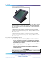
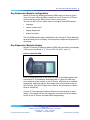
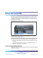
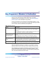
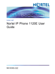
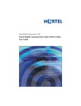
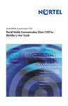
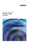
Carrier VoIP
Nortel IP Phone Key Expansion
Module User Guide
NN10300-011
.
Document status: Standard
Document version: 06.04
Document date: 20 October 2006
Copyright © 2006, Nortel Networks
All Rights Reserved.
The information in this document is sourced in Canada, the United States of America, and the United Kingdom.
This is the Way, This is Nortel, Nortel, the Nortel logo, the globemark design, and the NORTEL NETWORKS corporate
logo, are trademarks of Nortel Networks. All other trademarks are the property of their respective owners.
All rights reserved.
3
Contents
New in this release
5
Overview
7
IP Phone Key Expansion Module description
Key Expansion Module features 8
Key Expansion Module configuration 9
Key Expansion Module display 9
7
Setup and assembly
Installing a Key Expansion Module
Using the wall-mount option 12
Adjusting the tilt base 13
11
11
Key Expansion Module initialization
15
Controls and settings
17
Carrier VoIP
Nortel IP Phone Key Expansion Module User Guide
NN10300-011 06.04 Standard
(I)SN09U 20 October 2006
Copyright © 2006, Nortel Networks
.
Nortel Networks Confidential
4 Contents
Carrier VoIP
Nortel IP Phone Key Expansion Module User Guide
NN10300-011 06.04 Standard
(I)SN09U 20 October 2006
Copyright © 2006, Nortel Networks
.
Nortel Networks Confidential
5
New in this release
There have been no updates to the document in this release.
Carrier VoIP
Nortel IP Phone Key Expansion Module User Guide
NN10300-011 06.04 Standard
(I)SN09U 20 October 2006
Copyright © 2006, Nortel Networks
.
Nortel Networks Confidential
6 New in this release
Carrier VoIP
Nortel IP Phone Key Expansion Module User Guide
NN10300-011 06.04 Standard
(I)SN09U 20 October 2006
Copyright © 2006, Nortel Networks
.
Nortel Networks Confidential
7
Overview
This document describes Nortel IP Phone Key Expansion Module (KEM)
and how to use it with Nortel IP Phones in a Communication Server 2100
network.
IP Phone Key Expansion Module description
Nortel IP Phone Key Expansion Module (KEM) is a hardware component
that connects to an IP Phone to expand the number of fixed line and feature
keys available to the phone. The number of keys that are available is
determined by the Communication Server (CS2000) to which the IP Phone
or KEM is connected, and not the devices. When KEM is used with the
Centrex IP Client Manager (CICM), only 22 keys are available, despite there
being 24 physical keys on the KEM.
Keys on the KEM are displayed in two columns of 12 keys, with one column
on each side of a central liquid crystal display (LCD) screen. When deployed
with CICM, the top two keys of each column are not used. See "IP Phone
Key Expansion Module" (page 8).
When a KEM is installed on an IP Phone, the IP Phone controls the keys of
the KEM just as it does its native keys.
Carrier VoIP
Nortel IP Phone Key Expansion Module User Guide
NN10300-011 06.04 Standard
(I)SN09U 20 October 2006
Copyright © 2006, Nortel Networks
.
Nortel Networks Confidential
8 Overview
IP Phone Key Expansion Module
Each KEM has a desk-mount bracket and structural base plate to connect
the KEM to a Nortel IP Phone 2002, IP Phone 2004, or to another KEM.
You can connect a maximum of two KEMs to the IP Phone 2002 and the
IP Phone 2004.
A standalone IP Phone 2002 has 14 feature keys. Adding one KEM
increases the number of feature keys to 36. Adding two KEMs increases
this number to 58.
A standalone IP Phone 2004 has 11 feature keys. Adding one KEM
increases the number of feature keys to 33. Adding two KEMs increases
this number to 55.
Key Expansion Module features
The IP Phone Key Expansion Module (KEM) has the following features:
•
24 keys, arranged in two columns on the outside of an LCD display.
These keys provide a maximum of 44 additional, user-labeled feature
keys or lines, to the IP phone.
•
desk-mount bracket and structural base plate to connect the KEM to an
IP Phone 2002 or 2004, or to another KEM
•
wall-mount bracket to install the KEM alongside a wall-mounted IP
Phone 2002 or 2004
ATTENTION
When connected to a Centrex IP Client Manager, KEM has only 22 keys available.
The top key in each column is not used.
Carrier VoIP
Nortel IP Phone Key Expansion Module User Guide
NN10300-011 06.04 Standard
(I)SN09U 20 October 2006
Copyright © 2006, Nortel Networks
.
Nortel Networks Confidential
Key Expansion Module display 9
Key Expansion Module configuration
Nortel IP Phone Key Expansion Module (KEM) does not have an option
menu of its own. When a KEM is installed on an IP Phone, the IP Phone
controls the keys of the KEM just as it does its native keys.
You can use the IP Phone option menu to configure these KEM options:
•
language
•
screen contrast level
•
display diagnostics
•
feature key label
The only KEM-specific option available from the Centrex IP Client Manager
terminal setting menu is Display. Use this option to adjust the brightness of
the display.
Key Expansion Module display
Nortel IP Phone Key Expansion Module (KEM) has one liquid crystal display
(LCD) screen, as shown in "IP Phone 2002 with KEM" (page 9).
IP Phone 2002 with KEM
Each of the physical keys on the KEM can have a user-defined label (with
a maximum of 10 characters) associated with it. Labels for KEM keys
are created using the controls on the IP Phone. KEM keys are numbered
sequentially, beginning with the first number after the last defined key on
the IP phone. See the IP Phone User Guide for the procedure to create a
label for a KEM key.
Centrex IP Client Manager supports different contrast settings for each
display. This means that you can adjust the contrast level for the display
screen on the IP Phone, and each KEM independently.
Carrier VoIP
Nortel IP Phone Key Expansion Module User Guide
NN10300-011 06.04 Standard
(I)SN09U 20 October 2006
Copyright © 2006, Nortel Networks
.
Nortel Networks Confidential
10 Overview
Carrier VoIP
Nortel IP Phone Key Expansion Module User Guide
NN10300-011 06.04 Standard
(I)SN09U 20 October 2006
Copyright © 2006, Nortel Networks
.
Nortel Networks Confidential
11
Setup and assembly
Nortel IP Phone Key Expansion Module (KEM) mounts on the right side of
the IP Phone as shown in "KEM attached to an IP Phone 2002" (page 11).
A desk-mount bracket and a structural baseplate are provided, to secure
the KEM to the IP Phone.
KEM attached to an IP Phone 2002
KEM attaches to the IP Phone or another KEM through the accessory
expansion module (AEM) interface.
Extending from the left side of the KEM is a 10-pin female header on a ribbon
cable that is connected to inside of the module. Use this ribbon cable to:
•
connect the ribbon cable to the AEM connector on the right side of the
IP Phone.
•
connect the ribbon cable to the 10-pin recessed male connector on a
KEM that is connected to the IP Phone.
Installing a Key Expansion Module
Follow this procedure to connect a Nortel IP Phone Key Expansion Module
(KEM) to an IP Phone.
Carrier VoIP
Nortel IP Phone Key Expansion Module User Guide
NN10300-011 06.04 Standard
(I)SN09U 20 October 2006
Copyright © 2006, Nortel Networks
.
Nortel Networks Confidential
12 Setup and assembly
Step
Action
1
Remove the IP Phone from the stand by pressing the tilt handle and
pulling the phone away from the stand.
Instead of removing an IP Phone 2004 from the stand, you can
adjust the angle of the stand to maximum.
2
Place the IP Phone and the KEM face down on a nonabrasive
surface and align them.
3
Move the connecting arm of the KEM into the IP Phone and align the
connection plug to the accessory expansion module (AEM) port on
the back of the IP Phone.
Some older IP Phone 2002 models have shorter connector pins. If
your IP Phone 2002 has a short connector pin, detach the ribbon
cable connector from the retaining clip on the KEM and connect it to
the header connector on the IP Phone.
4
After the cable is attached to the phone, reconnect the ribbon cable
to the KEM.
The KEM starts when it is attached to a power source. The KEM
does not have its own power source, and it draws its power from the
IP Phone to which it is connected.
5
Wrap the clamp around the cable and screw the clamp into the back
of the IP Phone using a 3 mm and an 8 mm screw.
6
Thread the cable through the opening in the side of the IP Phone.
7
Insert the clips on the IP Phone into the hinges on the footstand and
then press onto the front of the footstand until it snaps into place.
8
While squeezing the IP Phone tilt handle, swing the footstand into
position.
9
Insert the clips on the KEM into the hinges on the module footstand,
and while squeezing the tilt handle on the module, swing the
footstand into the desired position.
—End—
Using the wall-mount option
The IP Phone and IP Phone Key Expansion Module (KEM) combination can
be wall-mounted using the optional bracket kit provided. A second KEM can
be attached to the right side of the first KEM.
Carrier VoIP
Nortel IP Phone Key Expansion Module User Guide
NN10300-011 06.04 Standard
(I)SN09U 20 October 2006
Copyright © 2006, Nortel Networks
.
Nortel Networks Confidential
Adjusting the tilt base 13
Adjusting the tilt base
The tilt base on the IP Phone 2002 cannot be adjusted. To match the angle
of the IP Phone and the Key Expansion Module (KEM), adjust the tilt base
on the KEM.
The IP Phone 2004 has an adjustable tilt base. Adjust the tilt of both the IP
Phone 2004 and the KEM, as needed.
Carrier VoIP
Nortel IP Phone Key Expansion Module User Guide
NN10300-011 06.04 Standard
(I)SN09U 20 October 2006
Copyright © 2006, Nortel Networks
.
Nortel Networks Confidential
14 Setup and assembly
Carrier VoIP
Nortel IP Phone Key Expansion Module User Guide
NN10300-011 06.04 Standard
(I)SN09U 20 October 2006
Copyright © 2006, Nortel Networks
.
Nortel Networks Confidential
15
Key Expansion Module initialization
Nortel IP Phone Key Expansion Module (KEM) starts and begins
initialization after it is connected to an IP Phone. See "KEM initialization
process" (page 15) for a description of the process.
In some circumstances on the Centrex IP Client Manager platform, it may
be necessary for the user to log off and log on again after attaching the KEM
to the IP Phone, before the KEM becomes operational.
KEM initialization process
Phase
Description
KEM performs self-test
The self-test confirms the operation of the module’s local memory,
CPU, and other circuitry. During the self-test, the module display
lights up.
If the display does not light up, or lights up and then goes blank, or fails
to begin flashing, contact your system administrator.
KEM establishes
communication with
the base IP phone
The KEM display flashes until it establishes communication with the IP
phone.
KEM downloads key
maps
KEM uses key maps to download feature key assignments. Key maps
are downloaded after communication is established with the IP Phone.
The KEM screen is blank until the key maps are downloaded.
Labels appear beside
the keys on the module
After the three initialization phases are complete, labels appear beside
the keys on the KEM. Keys assignments are made by the administrator.
If the display does not stop flashing, communication cannot be
established with the IP Phone. Contact your system administrator.
After the initialization sequence is complete, you can begin to use the
additional feature and line (DN) keys that are available through the KEM.
If two modules are connected to the IP Phone, the first one in the series
must be functioning in order for the second module to operate. This is
because the second module depends on the first module to provide power
from, and communication with, the IP Phone.
Carrier VoIP
Nortel IP Phone Key Expansion Module User Guide
NN10300-011 06.04 Standard
(I)SN09U 20 October 2006
Copyright © 2006, Nortel Networks
.
Nortel Networks Confidential
16 Key Expansion Module initialization
Carrier VoIP
Nortel IP Phone Key Expansion Module User Guide
NN10300-011 06.04 Standard
(I)SN09U 20 October 2006
Copyright © 2006, Nortel Networks
.
Nortel Networks Confidential
17
Controls and settings
When a Nortel IP Phone Key Expansion Module (KEM) is installed on an IP
Phone, the controls and settings of the IP Phone control both the IP Phone
and the KEM. Use the IP Phone menu options to adjust the display contrast
and change the labels of the feature keys.
For more information about controls and settings, see the IP Phone User
Guide.
Carrier VoIP
Nortel IP Phone Key Expansion Module User Guide
NN10300-011 06.04 Standard
(I)SN09U 20 October 2006
Copyright © 2006, Nortel Networks
.
Nortel Networks Confidential
18 Controls and settings
Carrier VoIP
Nortel IP Phone Key Expansion Module User Guide
NN10300-011 06.04 Standard
(I)SN09U 20 October 2006
Copyright © 2006, Nortel Networks
.
Nortel Networks Confidential
Carrier VoIP
Nortel IP Phone Key Expansion Module User Guide
Copyright © 2006, Nortel Networks
All Rights Reserved.
Publication: NN10300-011
Document status: Standard
Document version: 06.04
Document date: 20 October 2006
To provide feedback or report a problem in this document, go to www.nortel.com/documentfeedback.
The information in this document is sourced in Canada, the United States of America, and the United Kingdom.
The information contained herein is the property of Nortel Networks and is strictly confidential. Except as expressly authorized in
writing by Nortel Networks, the holder shall keep all information contained herein confidential, shall disclose it only to its employees
with a need to know, and shall protect it, in whole or in part, from disclosure and dissemination to third parties with the same degree
of care it uses to protect its own confidential information, but with no less than reasonable care. Except as expressly authorized in
writing by Nortel Networks, the holder is granted no rights to use the information contained herein.
This is the Way, This is Nortel, Nortel, the Nortel logo, the globemark design, and the NORTEL NETWORKS corporate logo, are
trademarks of Nortel Networks. All other trademarks are the property of their respective owners. All rights reserved.