1
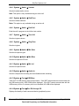
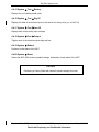
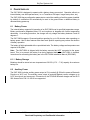
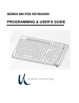
ISAT-200A User Guide DOC1037 Document Revision 01.001 Applies to: ISAT-200A Note: The latest revision of this document is available via the ‘Customer Support’ link at www.skytrac.ca March 28, 2014 SkyTrac Systems Ltd. 200-170 Rutland Road Kelowna, BC Canada Tel. +1 250 765-2393 Fax +1 250 765-3767 Web: www.skytrac.ca Email: [email protected] Copyright © 2014 SkyTrac Systems Ltd. All rights reserved. SkyTrac Systems Ltd. Document Revision History Rev ECO Page 01.000 01.001 564 675 All All Description Date Author Initial Release CHM, FDM, WiFi-200 Nov 7, 2012 Mar 28, 2014 MR BB ESD Caution The ISAT-200A contains static sensitive circuitry that could be damaged from large electrostatic discharges directly into the ARINC 404 connector pins. Use care when handling the ISAT-200A not to touch the connector pins unless properly grounded. Disclaimer Devices other than the ISAT-200A and ITRAY-200A mentioned in this manual do not necessarily have regulatory approval for installation in your airframe and may require additional approvals. Please refer to the applicable STC for approval information. Warning Changes or modifications not expressly approved by SkyTrac Systems Ltd (STS) could void the user’s authority to operate the equipment. Proprietary Notice The information contained in this document is proprietary and confidential to SkyTrac Systems Ltd. No part of this document may be reproduced or transmitted in any for or by any means, electonic or mechancial, without express written permission from SkyTrac Systems Ltd. Document Rev. 01.001 DOC1037 Restricted Proprietary and Confidential Information Page 2 of 29 SkyTrac Systems Ltd. Table Of Contents 1 General.............................................................................................................................. 5 1.1 About This Document ................................................................................................. 5 1.1.1 Purpose .................................................................................................................. 5 1.1.2 Glossary of Terms and Abbreviations ..................................................................... 5 1.2 Description of Equipment ............................................................................................ 6 1.2.1 ISAT-200A .............................................................................................................. 6 1.2.2 ITRAY-200A ........................................................................................................... 7 1.2.3 Antenna .................................................................................................................. 7 1.2.4 ISAT-200A Supported Peripheral Devices .............................................................. 7 1.3 Features ..................................................................................................................... 9 1.3.1 Automatic Position Reporting .................................................................................. 9 1.3.2 Emergency Mode.................................................................................................... 9 1.3.3 History on Demand ................................................................................................. 9 1.3.4 Wheels and Mission On/Off Event Reporting .........................................................10 1.3.5 Two-Way Voice Communication & Messaging .......................................................10 1.3.6 Cockpit Audio and Flight Data Retrieval .................................................................10 2 System Configuration .....................................................................................................11 2.1 SkyWeb Configuration ...............................................................................................11 2.2 Audio Configuration ...................................................................................................11 2.2.1 Microphone DC Bias ..............................................................................................11 2.2.2 Microphone Input Level..........................................................................................11 2.2.3 Microphone Gain ...................................................................................................11 2.2.4 Ring Tone ..............................................................................................................12 3 Interfaces .........................................................................................................................13 3.1 Serial Communications ..............................................................................................14 3.1.1 RS-232 ..................................................................................................................14 3.1.2 RS-422 ..................................................................................................................14 3.1.3 RS-485 ..................................................................................................................14 3.1.4 ARINC 429 ............................................................................................................14 3.2 Ethernet .....................................................................................................................15 3.3 Mobile Devices ..........................................................................................................15 3.4 CDP/DVI ....................................................................................................................15 3.5 Data and Voice Recorder ..........................................................................................16 3.6 Crash Hardened Memory Module ..............................................................................16 3.7 Flight Data Monitoring................................................................................................16 3.8 Accelerometer ...........................................................................................................17 3.9 Inputs/Outputs ...........................................................................................................17 3.9.1 Analog Inputs.........................................................................................................17 3.9.2 Discrete Inputs .......................................................................................................17 3.9.3 Emergency Input....................................................................................................17 3.9.4 Wake-up Input .......................................................................................................17 3.9.5 Discrete Outputs ....................................................................................................18 3.10 Audio Interfaces.........................................................................................................18 3.10.1 Aircraft Audio .....................................................................................................18 3.10.2 DPL Handset .....................................................................................................19 3.10.3 POTS .................................................................................................................20 3.10.4 Cockpit Audio.....................................................................................................20 3.11 SMS ..........................................................................................................................20 3.12 RUDICS.....................................................................................................................21 Document Rev. 01.001 DOC1037 Restricted Proprietary and Confidential Information Page 3 of 29 SkyTrac Systems Ltd. 3.13 Front Panel ................................................................................................................21 3.13.1 Status LED.........................................................................................................21 3.13.2 USB Host ...........................................................................................................21 3.14 ITRAY-200.................................................................................................................21 3.15 Configuration Module.................................................................................................21 4 Menu System ...................................................................................................................22 4.1 General Menu Information .........................................................................................22 4.1.1 Idle Screen ............................................................................................................22 4.1.2 Pushbutton ............................................................................................................22 4.2 Alert Menu .................................................................................................................24 4.3 Info Menu ..................................................................................................................24 4.3.1 Info FW Ver .......................................................................................................24 4.3.2 Info ISAT Ser.....................................................................................................24 4.3.3 Info Tray Ser .....................................................................................................24 4.3.4 Info GPS Lock ...................................................................................................24 4.3.5 Info GPS Sats ...................................................................................................24 4.3.6 Info Mdm Sig .....................................................................................................24 4.4 System Menu.............................................................................................................24 4.4.1 System FW Upgrade .........................................................................................24 4.4.2 System Save Log ..............................................................................................24 4.4.3 System Audio Call.........................................................................................24 4.4.4 System Audio Volume ...................................................................................25 4.4.5 System Audio SideTone................................................................................25 4.4.6 System Audio End Call .................................................................................25 4.4.7 System Audio Tone Vol ................................................................................25 4.4.8 System Audio RingTone ...............................................................................25 4.4.9 System Audio Mic Gain .................................................................................25 4.4.10 System Audio Mic Bias .............................................................................25 4.4.11 System Audio Mic Lvl ................................................................................25 4.4.12 System Audio Audio In ..............................................................................25 4.4.13 System Test USB Mem .............................................................................25 4.4.14 System Test Peri Q0 through Q3 ..............................................................25 4.4.15 System Test Battery ..................................................................................26 4.4.16 System Test Dig I/P ..................................................................................26 4.4.17 System Test Ana I/P .................................................................................26 4.4.18 System Test Output ..................................................................................26 4.4.19 System Reboot ..............................................................................................26 4.4.20 System Reset ................................................................................................26 5 Programming ...................................................................................................................27 5.1 5.2 6 Firmware Updates .....................................................................................................27 USB Port ...................................................................................................................27 Power Supplies ...............................................................................................................28 6.1 Battery Power ............................................................................................................28 6.1.1 Battery Storage ......................................................................................................28 6.2 Auxiliary Power ..........................................................................................................28 Document Rev. 01.001 DOC1037 Restricted Proprietary and Confidential Information Page 4 of 29 SkyTrac Systems Ltd. 1 GENERAL 1.1 About This Document 1.1.1 Purpose This document describes the features of the ISAT-200A once it is installed and active. For information on how to install the ISAT-200A, please see the ISAT-200A Installation Manual (DOC0843). 1.1.2 Glossary of Terms and Abbreviations Acronym ARINC ARINC 404 ARINC 429 CHM DO-160G DPL DTMF EMI ESD FDM FMEA FTA GPS HBM I/O ISAT MTBF OTAC PCM POTS RDA ROHS ROM RTCA SBD SIM STS Description Aeronautical Radio Incorporated (develops and maintains aviation standards) An ARINC form factor for line-replaceable electronics units in aircraft An ARINC Aviation Communications Bus Standard Crash Hardened Memory An RTCA standard for “Environmental Conditions and Test Procedures for Airborne Equipment” Digital Peripheral Link (serial interface) Dual Tone Multiple Frequency (tones used for touch tone phones) Electromagnetic Interference Electrostatic Discharge Flight Data Monitoring Failure Modes and Effects Analysis File Transfer Application Global Positioning System Human Body Model (an Electrostatic Discharge model) Inputs and Outputs SkyTrac’s voice enabled Flight Following system Mean Time Between Failures Over the Air Command Pulse-Code Modulation Plain Old Telephone Service Remote Display Application (STS-RDA) Restriction of Hazardous Substances (a directive) Read-Only Memory Radio Technical Commission for Aeronautics (develops technical guidance for use by government regulatory authorities and by industry) Short Burst Data Subscriber Identity Module SkyTrac Systems Document Rev. 01.001 DOC1037 Restricted Proprietary and Confidential Information Context Aviation Aviation Aviation Eng. Aviation Iridium Telecom Eng. Eng. Aviation Eng. SkyTrac Navigation Eng. Eng. SkyTrac Eng. SkyTrac Eng. Telecom SkyTrac Eng. Eng. Standards Iridium Iridium SkyTrac Page 5 of 29 SkyTrac Systems Ltd. 1.2 Description of Equipment 1.2.1 ISAT-200A The ISAT-200A is a full-featured GPS and Iridium transceiver that provides voice, text messaging (email and SMS), flight following and data communications with global coverage in near real-time. An internal, field replaceable Lithium-ion battery and charging system enables communications with the Iridium satellite network after airframe shutdown. Figure 1– ISAT-200A Data can be sent between an aircraft and any point in the world with internet access via the Iridium Low Earth Orbit (LEO) satellites. Position reports and text messages from the aircraft can be displayed on any computer (and some personal devices such as smart phones) with a web browser and internet access and SkyTrac software. Position reporting intervals are user-defined. The web based flight following software displays present and historical position data including latitude, longitude, GPS time, relative position (to a known way point), ground speed, altitude and heading, in tabular format and on a map. Airtime, flight time, ETA, distance traveled, time elapsed and other flight data is also displayed for instant viewing. Flight reports can also be generated by unit and time frame (i.e. airtime/flight time per day/week/month). The ISAT-200A can be reprogrammed via the USB port to provide new features as they become available. An eight character display and user-friendly menu system is provided to enable configuration and troubleshooting with minimal reference to the manual required. The ISAT-200A supports up to two RS-232 serial ports, one RS-485 port, two RS-422 ports, seven ARINC 429 receivers, one ARINC 429 transmitter and Ethernet. Document Rev. 01.001 DOC1037 Restricted Proprietary and Confidential Information Page 6 of 29 SkyTrac Systems Ltd. The ISAT-200A provides four differential analog inputs, one single ended analog input, eight general purpose discrete inputs, one Emergency discrete input, one Wake-Up discrete input and five discrete outputs. The ISAT-200A supports sat phone integration into aircraft standard audio equipment and provides connectivity for DPL and POTS handsets. Other notable features include an accelerometer for exceedance monitoring and a hardened memory module that records flight data as well as audio from the cockpit audio recorder input. 1.2.2 ITRAY-200A The ISAT-200A is mounted in an ITRAY-200A quick disconnect chassis. The ITRAY-200A makes for easy replacement and maintenance of the ISAT-200A. The ITRAY-200A onboard Configuration Module retains the configuration information related to the airframe, so that if the ISAT-200A is replaced, the new unit will be easily reconfigured. If an ISAT-200A is moved from one ITRAY-200A to another, the ISAT-200A will automatically use the configuration contained in the new ITRAY-200A. Figure 2-- ITRAY-200A 1.2.3 Antenna The SkyTrac combination antenna combines a passive Iridium antenna and an active GPS antenna into a single package with a small footprint. The antenna is qualified to TSO-C144. It is recommended that only the SkyTrac combination antenna be used with the ISAT-200A system. If you wish to use an antenna other than the one provided; please contact SkyTrac Systems for assistance. 1.2.4 ISAT-200A Supported Peripheral Devices The ISAT-200A supports the following SkyTrac cockpit interface products: DVI-300 Dispatch Voice Interface (DVI-300C, DVI-300A) Document Rev. 01.001 DOC1037 Restricted Proprietary and Confidential Information Page 7 of 29 SkyTrac Systems Ltd. CDP-300 Cockpit Display Panel (CDP-300G, CDP-300C) Combined CDP-300/DVI-300 It is recommended that a DVI-300 and CDP-300 be used in conjunction to make full use of the ISAT-200A features. Additional peripherals may become available from time to time. Please go to www.skytrac.ca or contact SkyTrac Client Services for more information. Table 1- Supported Peripherals Type Part Number Description DVI-300C DVI-300A DVI-300CP DVI-300AP CDP-300G CDP-300C 105-300-01 105-300-02 105-300-03 105-300-04 104-300-01 104-300-02 DVI-300 NVIS Friendly DVI-300 NVIS Compatible DVI-300 NVIS Friendly, Push Button DVI-300 NVIS Compatible, Push Button CDP-300 Commercial CDP-300 NVIS Friendly Note: Please refer to the firmware section of SkyTrac’s website www.skytrac.ca for the latest version of the approved firmware for peripherals. Table 2- ISAT-200A System Type Part Number Description Compatibility ISAT-200A 101-200-05 ISAT-200A - Qualified to RTCA/DO-160G 102-200-05 102-200-01* ITRAY-200A 102-200-05 ITRAY-200A/Installation Kit for ISAT-200A (or ISAT-200) 101-200-05 101-200-03** Li-ion 7.2V STS0061 Lithium-Ion 7.2V battery 101-200-05 101-200-03** Antenna STS-ISAT-ANT SkyTrac TSO Iridium/GPS Antenna 101-200-05 101-200-03** * 102-200-01 = ITRAY-200R ** 101-200-03 = ISAT-200R Document Rev. 01.001 DOC1037 Restricted Proprietary and Confidential Information Page 8 of 29 SkyTrac Systems Ltd. 1.3 Features 1.3.1 Automatic Position Reporting Once the unit has been activated (by the user’s SkyTrac Program Manager or their designated representative via SkyWeb) and power applied then position data will be sent by the ISAT-200A to the ground at a predefined interval. The initial default reporting interval will be 1 minute and will commence at either the ‘Transceiver On’ or ‘Engines On’ event depending on how the aircraft is wired. Other events can also be configured that will cause the aircraft to change color in SkyWeb and also vary the reporting interval (if required). 1.3.2 Emergency Mode The ISAT-200A has an Emergency Mode that is activated by the flight crew and increases the frequency of position reports to a faster interval (configured by users). Emergency Mode can be initiated using a switch directly connected to the ISAT-200A, the DVI-300 emergency switch, CDP menu system, or RDA. When Emergency Mode is activated the ISAT-200A can: Automatically increase the position reporting interval time Send an email or text message notification to the designated recipients Change the color of the aircraft icon in SkyWeb to bright red, and give a visual and audible alert Send a ‘History on Demand’ (HOD) report (enabled by default) The ISAT-200A is equipped with an internal battery, which under normal flight conditions, powers the unit for transmission of the main power off report (Transceiver/Engines Off). When Emergency Mode is activated the internal battery allows the ISAT-200A to transmit position reports and/or custom data until the battery is depleted. Phone calls can be made during emergency activation with the ISAT-200A. 1.3.3 History on Demand The ISAT-200A maintains history of aircraft parameters which can be automatically sent to SkyWeb when an event occurs. The maintained parameters include: GPS altitude and velocity Acceleration (x, y, z) ARINC 429 data Discrete inputs’ status Analog inputs’ status The types of events that trigger a History on Demand report and the parameters sent when an event occurs are configurable. Contact SkyTrac Client Services for further information or assistance. Document Rev. 01.001 DOC1037 Restricted Proprietary and Confidential Information Page 9 of 29 SkyTrac Systems Ltd. 1.3.4 Wheels and Mission On/Off Event Reporting As well as the Emergency event reporting, the unit can also be provided with inputs from additional items such as a squat switch/collective for air time and also a mission switch. The position interval for these different events can also be varied within SkyWeb. For example (as long as the relevant input has been wired in the aircraft) if a Mission Switch is activated, the reporting interval could be set to every 2 minutes and again the aircraft would change to a different color in SkyWeb until the switch was deactivated. These intervals are determined by the client and entered in SkyWeb by the client’s Program Manager or their designate. 1.3.5 Two-Way Voice Communication & Messaging The ISAT-200A provides full-duplex voice communication which can be established from any point in the world via Iridium Low Earth Orbit (LEO) satellites. The unit can also provide two-way text messaging (air to ground and ground to air) if the relevant control head is fitted. 1.3.6 Cockpit Audio and Flight Data Retrieval Up to 2 hours of cockpit audio plus more than 20 hours of the last active flight data are stored in the non-volatile memory module and can be retrieved via the front panel USB port. Document Rev. 01.001 DOC1037 Restricted Proprietary and Confidential Information Page 10 of 29 SkyTrac Systems Ltd. 2 SYSTEM CONFIGURATION 2.1 SkyWeb Configuration Some system configuration can be done via SkyWeb. This includes configuring the registration number in the ITRAY-200A, position reporting information and intervals, the operation of the configurable inputs and other parameters. This configuration is normally done by the user’s SkyWeb Program Manager (or their designated Hardware Manager representative). Refer to the SkyWeb Administrator’s Guide for more details. This document is available via the ‘Customer Support’ link on SkyTrac’s website www.skytrac.ca. Login credentials can be requested from [email protected]. 2.2 Audio Configuration Audio configuration involves setting the audio volume, side tone, microphone DC bias, microphone input level, microphone gain and ring tone. Microphone DC bias and microphone input level are normally configured during installation. The remaining settings can be configured by the user. Volume and side tone settings can only be adjusted during an active call and can be changed from the ISAT-200A menu, the CDP menu or using RDA. Microphone DC bias, microphone input level, ringtone and ringtone volume cannot be adjusted during an active call. 2.2.1 Microphone DC Bias Microphone DC Bias can be set ON or OFF using the ISAT-200A menu: System>Audio>Mic Bias to toggle the DC Bias (ON) or No Bias (OFF) setting. Note: This parameter is normally configured during installation and is not intended to be modified during operation. 2.2.2 Microphone Input Level The microphone input level can be selected to a low range designed to connect to microphones, or to a high range accepting up to 5 Vrms. The microphone input level can be set using the ISAT200A menu: System>Audio>Mic Lvl. Select ‘Lo Level’ for low input range microphones or ‘Hi Level’ for high input range. Note: This parameter is normally configured during installation and is not intended to be modified during operation. 2.2.3 Microphone Gain Microphone gain can be set using the ISAT-200A menu: System>Audio>Mic Gain. Selecting level 1 to 3 will set the microphone gain to that level. Document Rev. 01.001 DOC1037 Restricted Proprietary and Confidential Information Page 11 of 29 SkyTrac Systems Ltd. 2.2.4 Ring Tone One of six ring tones can be selected via menus on the ISAT-200A, CDP, or RDA. To select a ring tone using the front panel menu go to the System>Audio>RingTone menu and select ring tone 0 to 5. As each number is displayed, the associated ring tone will sound for one second in the headset. To set the ring tone volume go to the System>Audio>Ring Vol menu option. When cycling through the ring tone volume settings the ringtone plays for each level indicating how loud the ring will be. Selecting any number will set the ring tone volume to that level. Start by selecting ‘4’. If the selected ring tone is not heard, increase the volume and try again. Document Rev. 01.001 DOC1037 Restricted Proprietary and Confidential Information Page 12 of 29 SkyTrac Systems Ltd. 3 INTERFACES Table 3: ISAT-200A External Interfaces vs. Part Numbers ISAT-200A Interfaces ISAT-200A Part Numbers 101-200-05 101-200-06 101-200-07 RS-232 Ports 2 2 2 RS-485 Ports 1 1 1 RS-422 Ports 2 2 2 Ethernet port 1 1 1 ARINC 429 Channels Receive Transmit 7 1 7 1 6 1 ARINC 717 Interface Receive (HBP, BPRZ) Transmit (HBP) 0 0 0 0 1 1 Discrete Inputs Configurable Standby 8 2 12 2 8 2 5 5 5 1 4 1 8 1 4 0 3 0 1 1 1 1 1 1 1 1 1 Audio Recorder Inputs 1 1 1 Auxiliary Power Output 1 1 1 GPS Antenna 1 1 1 Iridium Satellite Antenna 1 1 1 Discrete Outputs Analog Inputs Single Ended Differential Frequency Inputs Audio Interfaces Headset/Console DPL POTS Note: The ISAT-200A does not support both DPL and RS-232 port 2 to be used simultaneously. Note: The ISAT-200A does not support both POTS and DPL to be installed simultaneously. Document Rev. 01.001 DOC1037 Restricted Proprietary and Confidential Information Page 13 of 29 SkyTrac Systems Ltd. 3.1 Serial Communications 3.1.1 RS-232 The ISAT-200A provides one TIA/EIA-232-F compatible RS-232 interface that is capable of data rates up to 115,200 bps. The driver will tolerate continuous short circuits and uses slew rate control to reduce EMI emissions. 3.1.1.1 Wi-Fi and Bluetooth Support The RS-232 interface supports connection to the STS0043 Bluetooth dongle as well as the WiFi200. The ISAT-200A monitors the RS-232 receive line for a valid RS-232 signal level to detect when a Bluetooth or WiFi device is installed. 3.1.2 RS-422 The ISAT-200A provides two full-duplex ANSI TIA/EIA-422-B and TIA/EIA-485-A compatible interfaces. The interfaces are capable of data rates up to 115,200 bps. The interfaces implement software controlled transmit and receive enables. The receivers and drivers support common mode voltages +/-20V and will survive overvoltage faults of +/-60V.The receivers are failsafe for open-circuit, short-circuit and idle-bus conditions and implement 120 ohm termination. The RS-422 interfaces are DO-160G Sect.22 Cat. A3XXXX qualified to survive induced lightning effects. 3.1.3 RS-485 The ISAT-200A contains a Multi-Device RS-485 Interface which allows multiple peripherals to be connected simultaneously. Using this approach, the ISAT-200A is bus master and can interface to any combination of up to four CDP 300s, DVI 300s, and/or combined CDP-300/DVI-300s. The ISAT-200A provides one half-duplex ANSI EIA/TIA-485-A compatible interface. It is capable of data rates up to 115,200 bps and implements software controlled transmit / receive direction selection. The receivers and drivers support common mode voltages of +/-20V and will survive overvoltage faults of +/-60V. The receivers are failsafe for open-circuit, short-circuit and idle-bus conditions and implement 120 ohm termination. 3.1.4 ARINC 429 ARINC 429 is a standard avionics data bus with a single transmitter and multiple listeners. The ISAT-200A provides seven ARINC 429 receivers and one ARINC 429 transmitter. These receivers can be connected to existing aircraft ARINC 429 busses and allow the ISAT-200A to access aircraft flight data. The data can then be used to create any number of data products of interest or to trigger events. The ARINC 429 transmitter and receivers support both high and low speed operation. All ARINC 429 bus interfaces are DO-160G Sect.22 Cat. A3XXXX qualified to survive induced lightning effects. Document Rev. 01.001 DOC1037 Restricted Proprietary and Confidential Information Page 14 of 29 SkyTrac Systems Ltd. The ISAT-200A, by configuration, can receive any ARINC label on the channels connected to it. All ARINC words are decoded (based on configurable parameters) so that they can be numerically processed like the other signals in the system for exceedance checks. The standard word types include: Binary Coded Decimal (BCD) Binary Number Representation (BNR) Discrete data Floats The ISAT-200A can redirect received labels out of its own transmitter. 3.2 Ethernet Whenever an Ethernet cable is connected the ISAT-200A attempts to automatically receive an IP address from a DHCP server before falling back to the user-configurable IP address (default 192.168.1.120, mask 255.255.255.0, and gateway 192.168.1.255). The Ethernet port supports 10/100 Mbit/s* Ethernet and IPv4. * Note: Connection speed only. Actual throughput may vary. 3.3 Mobile Devices A mobile device (Blackberry, iPhone, Android) can be connected to the ISAT-200A through a serial-wireless converter device (i.e. Bluetooth, Wi-Fi). The mobile device can then be used as an interface into the ISAT-200A similar to a CDP-300 and/or DVI-300. RDA supports the following features for mobile devices: 3.4 Phone call control and status Sending/Receiving emails and text messages Flight Number Emergency Mode control ISAT-200A status and diagnostics information Audio configuration CDP/DVI The Cockpit Display Panel (CDP) and the Dispatch Voice Interface (DVI) are used to provide a phone and email/text message interface. The CDP and DVI can be combined to provide full functionality. The ISAT-200A supports interfacing with up to four CDP-300s, DVI-300s, and combined CDP/DVIs in any combination using the Multi-Device RS-485 interface. Document Rev. 01.001 DOC1037 Restricted Proprietary and Confidential Information Page 15 of 29 SkyTrac Systems Ltd. The ISAT-200A supports the following features for each device 3.5 Phone call control and status Sending/Receiving emails and text messages Flight Number Emergency Mode control ISAT-200A status and diagnostics information Audio configuration Data and Voice Recorder The ISAT-200A is capable of recording flight data and cockpit audio to a non-volatile memory module. Cockpit audio is recorded in WAV file format. When audio is wired into the ISAT-200A it is continuously recorded (with no user intervention). Recorded data can be downloaded to a USB stick using the front panel USB connector. To download flight and audio data using the front panel menu navigate to: ‘System>Save Log>Aud. Log’ (for audio) or ‘System>Save Log>Data Log’ (for data) and the relevant file will be written to the USB stick. 3.6 Crash Hardened Memory Module The data and voice recordings can be stored on a separate Crash Hardened Memory module (113-200-01) via the RS-422 serial bus. The CHM has a capacity of at least 2 Gigabytes and allows storage of up to 2 hours of cockpit audio recording and over 20 hours of flight data. The CHM is designed to meet EUROCAE ED-155 Crash Survivability. In the event of a crash there may be valuable data stored prior to when the aircraft crashed and lost power. The device must be carefully removed and returned to SkyTrac Systems Engineering department for analysis. Any regulatory agencies that may be involved in an accident investigation may wish to be present when the CHM is examined. Please contact SkyTrac Client Services to configure the CHM module. 3.7 Flight Data Monitoring The ISAT-200A has two optional interface modules available, which can be identified by the ISAT part number. Part number 101-200-06 has additional analog, discrete and engine interfaces, and are DO-160G Sect.22 Cat. A3XXXX qualified to survive induced lightning effects. The 101-200-07 ARINC 717 is DO-160G Sect.22 Cat. A3XXXX, A4XXXX and B4XXXX qualified to survive induced lightning effects. Refer to the appropriate installation manual for details. The FDM data will be continuously collected and stored on the memory module. If the aircraft is also equipped with a WiFi-200 (111-200-01), this data can be automatically downloaded to your base whenever the aircraft lands and the WiFi-200 connects to a local Wi-Fi hotspot at the hangar or terminal. Refer to the WiFi-200 User guide for details on configuring the automatic download. Please contact Client Services to enable and configure the FDM module for either part number 101-200-06 or 101-200-07. Document Rev. 01.001 DOC1037 Restricted Proprietary and Confidential Information Page 16 of 29 SkyTrac Systems Ltd. 3.8 Accelerometer The ISAT-200A contains an internal 3-axis accelerometer. Accelerometer readings are logged in ISAT memory and are downloadable via USB. Accelerometer data can also be sent to SkyWeb whenever a configured parameter is exceeded. See section 1.3.3 History on Demand for details or contact SkyTrac Client Services. ISAT-200A orientation relative to the airframe must be configured in order to provide proper readings (this procedure is described in the ISAT-200A Installation Manual (DOC0843)). 3.9 Inputs/Outputs 3.9.1 Analog Inputs The ISAT-200A provides 1 single ended and 4 differential analog inputs. Each input’s sampling rate and gain can be configured. Contact SkyTrac Systems for further information. Note: Only Analog Input 1 is enabled by default. Operation of the analog inputs can be checked from the ISAT-200A menu System>Test>Ana I/P. See the ISAT-200A Installation Manual (DOC0843) for further details. 3.9.2 Discrete Inputs The ISAT-200A provides eight multi-level discrete inputs. The discrete inputs are configurable and can be used as voltage seeking or ground seeking inputs. Ground seeking pins indicate a logical TRUE to the ISAT-200A if the input is grounded. Voltage seeking pins indicate a logical TRUE to the ISAT-200A if >14V is applied to the input. Discrete input 4 can also be configured to indicate a logical TRUE if >5V is applied. These inputs are capable of detecting Open/+28VDC, Open/GND and report these levels to software. DIN4 is also capable of detecting +5VDC/OPEN. Operation of the discrete inputs can be checked from the ISAT-200A menu System>Test>Dig I/P. See the ISAT-200A Installation Manual (DOC0843) for further details. 3.9.3 Emergency Input The ISAT-200A provides a dedicated ground seeking “Emergency Input” hardwired to ARINC 404 Connector Bay A pin 6. An active low signal level on the Emergency Input will wake-up the ISAT200A from Standby Mode and prevent it from shutting down when aircraft power is removed. The Emergency Input is DO-160G Sect.22 Cat. A3XXXX qualified to survive induced lightning effects. 3.9.4 Wake-up Input The ISAT-200A provides a dedicated ground seeking “Wake-up Input hardwired to ARINC 404 Connector Bay B pin 60. An active low signal level on the Wake-up Input will wake-up the ISAT200A from Standby Mode and prevent it from shutting down when aircraft power is removed. When the Wake-up Input is asserted the ISAT-200A will run on battery power allowing a user to place a phone call. Document Rev. 01.001 DOC1037 Restricted Proprietary and Confidential Information Page 17 of 29 SkyTrac Systems Ltd. The Wake-up Input is DO-160G Sect.22 Cat. A3XXXX qualified to survive induced lightning effects. 3.9.5 Discrete Outputs The ISAT-200A provides 5 ground sinking discrete outputs capable of sinking up to 1A continuously. They are protected against permanent damage from over current and are able to switch below 0.8V. They are designed to switch relays with a load inductance of 100mH at up to 400mA output current. The ISAT-200A can control any of the 5 output pins based on the state of a user-configurable event gate. The output pin is configurable to either: Follow the event gate state, Latch the event gate until the next power cycle, Pulse the pin once, or Toggle the output pin at a user-defined rate while the event gate is active. Operation of the discrete outputs can be checked from the ISAT-200A menu System>Test>Output. See the ISAT-200A Installation Manual (DOC0843) for further details. 3.10 Audio Interfaces All audio volume levels, including side-tones, are software configurable. The audio path to the satellite modem is available to only one audio interface at a time. Either one DPL handset or a POTS system with up to two POTS handsets can be installed. Note: DPL and POTS handsets cannot coexist in the same installation. 3.10.1 Aircraft Audio The aircraft audio output is capable of driving 150 mW into 300 or 600 ohm loads. The aircraft audio input accepts audio input levels up to 5 Vrms and has a minimum input impedance of 500 ohm (this allows for microphone and panel signals). See Section 2.2 Audio Configuration for details. Document Rev. 01.001 DOC1037 Restricted Proprietary and Confidential Information Page 18 of 29 SkyTrac Systems Ltd. 3.10.2 DPL Handset The ISAT-200A can be connected to an Iridium DPL handset, which provides a basic phone and messaging interface (email and SMS) through the ISAT-200A modem. The ISAT-200A detects when a DPL handset has been plugged in and turned on. Figure 3- DPL Handset Note: The DPL handset is not intended to replace a cockpit interface or provide any further ISAT-200A interaction (i.e. emergency, etc.). 3.10.2.1 General When the handset is on the Home screen then pressing any key will activate the menu. Pressing a number, star (*) or pound (#) will cause dialling to commence. Pressing the envelope (message) button will take the user straight to the message menu. Within a menu: Use Up/Down keys to navigate To select an option use Right/OK key To go up a menu level use Left/C key Select the Power button to return to the Home Screen 3.10.2.2 Making a Call Pressing a number, star (*) or pound (#) will cause dialling to commence. 3.10.2.3 Editing a Message To switch between entry modes (upper case/lower case/numbers/symbols) use the up arrow key to the right of the message key. 1-9 and 0 keys enter appropriate character/number/symbol Document Rev. 01.001 DOC1037 Restricted Proprietary and Confidential Information Page 19 of 29 SkyTrac Systems Ltd. To insert a space select # (small right-arrow). (press and hold will insert the # symbol) To backspace select * (small left-arrow). A press and hold of this button will insert the * symbol To cancel editing select any of the message key (envelope), ‘C’ or Power button To navigate the text use Up/Down or MR/M+ To insert a carriage-return (aka ‘Enter’) press and hold MR/M+ To scroll through the messages use left and right To scroll through (read) a message - use the up and down keys To reply select the up arrow To delete press ‘C’ then ‘OK’ To come out of the current message press ‘C’ twice 3.10.3 POTS The POTS interface can decode DTMF tones and provide the data to the Microprocessor. The POTS line interface can support up to two POTS handsets simultaneously. It will support unbalanced ringing and short loop telephony only. The POTS interface will support a low power shutdown mode activated while the POTS device is on-hook. It will generate call progress tones to the POTS handset. The interface will detect the on-hook and off-hook state of the POTS line. It will generate hook state change events to the Microprocessor. The POTS audio will implement side-tone. 3.10.4 Cockpit Audio The ISAT-200A provides an audio input for cockpit audio which is digitized and recorded in-flight. The cockpit audio input accepts audio input levels up to 14 Vrms. The audio input level is set using the ISAT-200A menu: System>Audio>Audio In. Select ‘Hi Gain’ for low input range up to 3.5 Vrms or ‘Lo Gain’ for high input range, up to 14 Vrms. Note: Cockpit Audio Input Level is normally configured during installation and is not intended to be modified during operation. 3.11 SMS SMS is enabled by default and is assigned to peripheral device queue 1. The ISAT-200A can send messages up to 160 characters and can receive concatenated (or ‘long’) SMS messages greater than 160 characters. Multimedia SMS messages (pictures, videos) are not supported. The ISAT-200A can hold 25 incoming SMS messages and can queue 25 outgoing SMS messages. Messages received when the inbox is full will be discarded so it is important to manage the inbox. The SMS inbox is cleared by default if the ISAT-200A is placed in a different ITRAY200A. Document Rev. 01.001 DOC1037 Restricted Proprietary and Confidential Information Page 20 of 29 SkyTrac Systems Ltd. 3.12 RUDICS The Iridium Router-based Unrestricted Digital Interworking Connectivity Solution (RUDICS) is an enhanced capability for data calls across the Iridium satellite network. The ISAT-200A system uses the RUDICS protocol to allow users to send files (up to a maximum of 1MB in size) from a PC in the aircraft through the ISAT-200A to predefined email recipients using SkyTrac’s File Transfer Application (STS-FTA). For additional information see STS-FTA User Guide (DOC0986) available via the ‘Customer Support’ link on SkyTrac’s website www.skytrac.ca. 3.13 Front Panel The ISAT-200A front panel includes a green 8-character display, pushbutton switch, status LED and USB host interface. The display and pushbutton switch are used to access the ISAT-200A menu system. See section 4 Menu System for details. 3.13.1 Status LED The ISAT-200A has a dual-color green/amber LED which indicates power and alert status. A steady green LED indicates the ISAT-200A has power and is operating normally. Refer to Table 4- LED Status below for details. Table 4- LED Status LED Status ISAT-200A Status LED Off Green LED On Solid Amber LED On Solid ISAT-200A is powered off ISAT-200A is powered on and running normally ISAT-200A is powered on but there is an Alert condition ISAT-200A is in programming mode and is waiting for a program Amber LED flashing fast Amber LED flashing slowly ISAT-200A is being programmed 3.13.2 USB Host The ISAT-200A provides a USB 2.0 full speed (12 Mbps) host interface through a female Type-A connector located on the front panel. The USB host interface can power a single USB device (up to 100mA). 3.14 ITRAY-200 When an ISAT-200A is installed in an ITRAY-200R (part # 102-200-01) it will retain the ISAT200R functionality as a minimum. An ISAT-200R can be installed in an ITRAY-200A with no loss of ISAT-200R functionality. Contact SkyTrac Systems for further information. 3.15 Configuration Module The Configuration Module on the ITRAY-200A and ITRAY-200R stores a number of items of information about the aircraft/unit configuration. This allows the ISAT-200A to be swapped out as required, but the information in the module is kept for the new unit to reduce the amount of reconfiguration. Document Rev. 01.001 DOC1037 Restricted Proprietary and Confidential Information Page 21 of 29 SkyTrac Systems Ltd. 4 MENU SYSTEM 4.1 General Menu Information The ISAT-200A has an eight character alphanumeric display and a button. A simple menu system is implemented to enable the user to view the operational status of the ISAT-200A and perform basic troubleshooting. 4.1.1 Idle Screen The display will normally return to the idle screen and then turn off to conserve power when a menu action is completed or no actions or activity is in progress. The display will come on again when the button is pressed. The display will go to the ‘idle screen’: 3 seconds after a command has been completed, or a menu item is completed, or After 20 seconds of inactivity 4.1.2 Pushbutton The pushbutton on the ISAT-200A is used for scrolling through the menu system and accessing configuration options and messages. Pushbutton functions are described in Table 5- PushButton Functions. Table 5- Push-Button Functions Control Behaviour Description Press and hold the Select an item button for > 1 seconds or action Select the item currently displayed to be acted upon. If the displayed item is a menu, the next menu will be displayed. If the displayed item is an action, the action will be initiated. Press and release the button in < 1 seconds Go to the next item in the current menu list Scroll the menu For items that take a long time (> 5 seconds) for execution, a short press (<1s) will cancel the execution of the menu item. These items include: File Upload to USB File Download from USB Firmware Upgrade While the ISAT-200A is in Emergency Mode the front panel menu is disabled and an “Emerg” message is shown on the display. The ISAT-200A menu system is outlined in Figure 4- ISAT-200A Front Panel Menu. Document Rev. 01.001 DOC1037 Restricted Proprietary and Confidential Information Page 22 of 29 FW Upgr Save Log Audio Test Reboot Reset Document Rev. 01.001 DOC1037 Restricted Proprietary and Confidential Information Requires call inactive Requires call active Requires call active or dialing Requires Mdm Reg and call inactive Requires USB connected, NAND mounted and appropriate file to be found Resets to Factory Defaults Hard Reboot of ISAT Firmware version Serial Number Tray Number GPS Health Report # Satellites Report Modem CSQ FW Ver ISAT Ser Tray Ser GPS Lock GPS Sats Mdm Sig Requires Alert to be Active Item Eligibility ALERT INFO SYSTEM GPS Health Report Modem Registration Report Data Delay Report Battery Report BIT Report GPS Mdm Reg Mdm Dly Bat Flt BIT USB Mem Peri Q# Battery Dig I/P Ana I/P Output Out1: 1 ... Out5: 0 Ch1:123.1 ... Ch5:001.2 Hi Level* Lo Level* Each output set high and low Analog Input Voltage Change Mic Voltage Change Cockpit Level Change Mic Bias Change Ringtone 1** ... 10** DC Bias* No Bias* Change In-Call Volume, Ring Volume, Sidetone Volume, Mic Volume 1* ... 10* * indicates an item which takes effect when viewed. The selection of “Go Back” will restore the setting saved before the menu was viewed. ** indicates an item which will play a sample tone when viewed. The selection of “Go Back” will restore the setting saved before the menu was viewed. USB Connection Report Q# Report Battery Report Digital Inputs Report Saves data log Saves audio log Place call to Iridium Test # End active phone call Call End Call Volume Tone Vol Sidetone Ringtone Mic Gain Mic Bias Mic Lvl Audio In Data log Aud. log Upgrade to F/W version selected xx.xx.xx ... SkyTrac Systems Ltd. Figure 4- ISAT-200A Front Panel Menu System Page 23 of 29 SkyTrac Systems Ltd. 4.2 Alert Menu If an alert is present the Alert menu will be shown and can be selected to view details for the alert. 4.3 Info Menu 4.3.1 Info FW Ver Displays the current firmware version 4.3.2 Info ISAT Ser Displays the ISAT-200A serial number 4.3.3 Info Tray Ser Displays the ITRAY serial number 4.3.4 Info GPS Lock Displays the GPS Lock state 4.3.5 Info GPS Sats Displays the number of GPS satellites currently connected to the ISAT-200A. A larger number of satellites indicates better accuracy. 4.3.6 Info Mdm Sig Displays the signal strength of the modem (none, poor, weak, fair and good) 4.4 System Menu Note: Some System Menu options are only available when required or enabled. 4.4.1 System FW Upgrade Displays the list of all valid firmware version files found on the connected USB drive The selection of a firmware file from the FW Upgrade menu upgrades the ISAT-200A firmware to the selected version. 4.4.2 System Save Log Displays a menu to allow downloading of the ISAT-200A’s data log (including current parameters) or the ISAT’s audio log 4.4.3 System Audio Call Places a test call to the Iridium test number. Document Rev. 01.001 DOC1037 Restricted Proprietary and Confidential Information Page 24 of 29 SkyTrac Systems Ltd. 4.4.4 System Audio Volume Sets the headset audio volume Note: This option is only available during an active call. 4.4.5 System Audio SideTone Sets the headset sidetone Note: This option is only available during an active call. 4.4.6 System Audio End Call Ends the call in progress to the Iridium test number 4.4.7 System Audio Tone Vol Sets the ringtone volume 4.4.8 System Audio RingTone Sets the ringtone 4.4.9 System Audio Mic Gain Sets the microphone gain 4.4.10 System Audio Mic Bias Sets the microphone DC bias 4.4.11 System Audio Mic Lvl Sets the microphone level 4.4.12 System Audio Audio In Sets the cockpit audio recording level and disables audio streaming 4.4.13 System Test USB Mem Tests ISAT to USB memory stick communication. If the ISAT detects and can communicate with the USB memory stick, USB CONN will be displayed. If the ISAT cannot communicate with the USB memory stick or if a memory stick is not installed, NO USB will be displayed. 4.4.14 System Test Peri Q0 through Q3 Displays the identity of each connected device (peripheral) queue Document Rev. 01.001 DOC1037 Restricted Proprietary and Confidential Information Page 25 of 29 SkyTrac Systems Ltd. 4.4.15 System Test Battery Displays the unit’s battery health state 4.4.16 System Test Dig I/P Displays the state of the discrete inputs in the format of a binary string (i.e. 01010110) 4.4.17 System Test Ana I/P Displays each of the Analog Input voltages 4.4.18 System Test Output Toggles each of the discrete outputs high and low 4.4.19 System Reboot Performs a hard reboot of the ISAT 4.4.20 System Reset Resets the ISAT-200A to factory default settings, followed by a hard reboot of the ISAT CAUTION: Performing a Factory Reset will cause all previous settings to be lost Document Rev. 01.001 DOC1037 Restricted Proprietary and Confidential Information Page 26 of 29 SkyTrac Systems Ltd. 5 PROGRAMMING 5.1 Firmware Updates The user can update the firmware on the ISAT-200A by the use of a USB memory stick via the System Menu. When a USB stick is inserted, the System>FW Upgrade menu option is available. When this is selected the ISAT-200A will verify that the file on the USB stick is intended for use by an ISAT200A and that the firmware is compatible with existing firmware. The ISAT-200A will then reprogram itself and reboot. Configuration parameters are maintained across firmware upgrades. 5.2 USB Port The ISAT-200A provides a USB Type-A host connection on the front panel. The ISAT-200A automatically detects insertion and removal of USB memory stick. It supports file copying to/from the USB memory stick for the following uses: Firmware upgrades Log downloads (audio and data) Parameter block downloads Note: The USB port is not designed for use during flight and should only be used for maintenance actions. Document Rev. 01.001 DOC1037 Restricted Proprietary and Confidential Information Page 27 of 29 SkyTrac Systems Ltd. 6 POWER SUPPLIES The ISAT-200A is designed to operate with a battery always connected. Operation without an internal battery can affect performance (i.e. no Transceiver Off report, longer startup time, etc.) The ISAT-200A has a configuration parameter to control the enabling of auxiliary power (enabled by default). A notification will automatically be sent to the ground when a dead/low battery is detected during power-up. 6.1 Battery Power The internal battery supports full operation of an ISAT-200A over its specified temperature range. Battery performance degrades below 0°C and continues to degrade with further temperature decreases. As a safety precaution, the charger will only charge the battery between 0 and 45 degrees C. The ISAT-200A supports 15-second position reporting for up to 30 minutes when operating on battery power. Use of other features other than basic position reporting may reduce the duration of battery operation. The battery is field replaceable with no specialized tools. The battery voltage and temperature are reported to SkyWeb. Note: The ISAT-200A is shipped with the battery mounted but NOT connected to the power board. This is to prevent the battery from being depleted before the ISAT-200A is installed. Instructions for connecting the battery are in the ISAT-200A Installation Manual (DOC0843). 6.1.1 Battery Storage Batteries should be stored at room temperature at 30-55% (6.7V – 7.3V) capacity for maximum battery life. 6.2 Auxiliary Power The ISAT-200A includes auxiliary power output of 6V (nominal) @ 500mA to power a Bluetooth Dongle or a Wi-Fi unit. The auxiliary power output is protected against reverse voltages up to 8.5V, short-circuit and overcurrent. Connection to the STS0043 Bluetooth dongle and the Wi-Fi 200 Access Point P/N 111-200-01 are supported. Document Rev. 01.001 DOC1037 Restricted Proprietary and Confidential Information Page 28 of 29 SkyTrac Systems Ltd. Copyright © 2014 SkyTrac Systems Ltd. All rights reserved. Document Rev. 01.001 DOC1037 Restricted Proprietary and Confidential Information Page 29 of 29