1
ISAT-200 Installation Manual
DOC0334
Document Revision: 01.019
Applies to PN: 101-200-01, 101-200-03 (ISAT-200)
102-200-01 (ITRAY-200)
July 27, 2012
SkyTrac Systems Ltd.
200-170 Rutland Road North
Kelowna, BC Canada
Tel. +1 250 765-2393
Fax +1 250 765-3767
Web: www.skytrac.ca
Email: [email protected]
Copyright © 2012 SkyTrac Systems Ltd.
All rights reserved.
SkyTrac Systems Ltd.
Document Revision History
Rev
ECO
Description
Date
01.000
164
Initial Release
Feb 10, 2009
01.001
168
Updates for initial production release.
May 4, 2009
Author
P. Bennett,
T. Ratch
A. Parker
01.002
01.003
01.004
181
182
187
June 25, 2009
June 29, 2009
July 17, 2009
T. Ratch
J. Van
A. Parker
01.005
188
July 21, 2009
D. McMahon
01.006
189
July 23, 2009
A. Parker
01.007
234
Nov 4, 2009
A. Parker
01.008
253
Feb. 11, 2010
G. Ross
01.009
270
Mar. 04, 2010
M. Hubert
G. Ross
01.010
340
Jul. 21, 2010
G. Ross
01.011
357
Sep. 10, 2010
Y. Liu
01.012
01.013
372
384
Nov. 15, 2010
Dec 15, 2010
D. McMahon
M. Hubert
01.014
390
Jan 5, 2011
J. James
01.015
397
Jan 28, 2011
J. James
01.016
439
June 1, 2011
M. Hubert
01.017
434
June 27, 2011
J. James
01.018
462
Apr 18, 2012
J. James
01.019
544
Corrected unit weight
Post-conformity updates
Changed DO-160E category
Correct CDP-300 Part number table, removed ISAT vertical
install spec
Changed operational temperature spec,
Made updates to Audio Config. Items
Update warranty statement to exclude the battery shipped
with the ISAT-200, added note about checking digital input
status and notes about alternate coax connector
Added installation functional test Instructions, added new
ISAT-200R CatM and ISAT-200S CatM. (This release is not
TC approved)
Updated Table 7 with operation temperature, short-term
operational temperature, and ITRAY-200 mounted physical
characteristics. Removed STS-ISAT-ANT from Table 4.
Corrected the voltage rating for STS-ISAT-ANT on Table
10. Added ITRAY-200 installation orientation to section 3.7.
Added a GND connection note to section 4.2.5. Added the
qualification of the ITRAY-200 to Table 12. Added
installation materials to Table 14. Corrected the weight of
the ISAT-200.
Labeled analog pins 2 and 3 as “Reserved. Do not use”.
Section 4.2.8 now says analogue inputs 1, 4, 5 can be
configured and analogue input 1 is preferred for engine
status. Section 1.3.1 references three analogue inputs now.
All references to ISAT-200S and ITRAY-200S deleted.
Added note to Section 1.3.5 that ISAT-200S and ITRAY200S have been discontinued.
Added note to section 1.3.2.
Added ESD Caution Statement, Fixed Formatting
Added ITRAY-200 to warranty statement. Added “from
SkyTrac Systems” to date of purchase in warranty
statement.
Changed “purchase” to “shipment” in warranty statement.
Added note about cable conversion needing additional
approval to 3.8.2.
Corrected DO-160 strings in section 2.6, Added row for
Section 26.0 to Table 12, Removed approval column from
Rev History.
Changed battery pack capacity rating to 2.25Ah. Added
CGR18650CG datasheet.
Removed EMTEQ A45240-1. Updated antenna note to
include pigtail. Added CDU-250 to list of supported
peripheral devices. Changed battery PN references to STS
PN.
Updated warranty information. Corrected battery connector
reference. Added STS0061 to battery references. Updated
battery specifications. Corrected battery cable tie tension.
Removed battery data sheets. Removed unit conversions.
Added step to apply mod status when replacing battery.
Jul 27, 2012
J. James
Document Rev. 01.019
DOC0334
Restricted Proprietary and Confidential Information
Page 2 of 48
SkyTrac Systems Ltd.
Caution
The ISAT-200 contains static sensitive circuitry that could be damaged from large electro static
discharges directly into the ARINC 404 connector pins. Use care when handling the ISAT-200 not to
touch the connector pins unless properly grounded.
Warning
Changes or modifications not expressly approved by SkyTrac Systems Ltd (STS) could void the
user’s authority to operate the equipment.
Warranty Information
SkyTrac Systems Ltd warrants this product to be free of defects in materials and workmanship, and
that the product meets or exceeds approved factory acceptance test requirements. STS reserves
the right to replace any warranted product at its sole discretion during the warranty period.
The ISAT-200 Airborne Data/Position Communicator (except for the Li-ion battery P/N: STS0044 or
STS0061) and ITRAY-200 Installation Kit are under warranty for one year from date of shipment
from SkyTrac Systems. For failed units caused by defective parts or workmanship, contact SkyTrac
Systems for an RMA #. Once an RMA # has been obtained, the unit should be returned to:
SkyTrac Systems Ltd.
#200-170 Rutland Road North
Kelowna, B.C. Canada
V1X 3B2
Proprietary Notice
The information contained in this document is proprietary and confidential to SkyTrac Systems Ltd.
No part of this document may be reproduced or transmitted in any form or by any means, electronic
or mechancial, without express written permission from SkyTrac Systems Ltd.
Document Rev. 01.019
DOC0334
Restricted Proprietary and Confidential Information
Page 3 of 48
SkyTrac Systems Ltd.
Table Of Contents
1
General ........................................................................................................................................................ 7
1.1
Introduction .......................................................................................................................................... 7
1.2
Contents............................................................................................................................................... 7
1.2.1 Audience.......................................................................................................................................... 8
1.2.2 References ...................................................................................................................................... 8
1.3
ISAT-200 System Components ........................................................................................................... 9
1.3.1 ISAT-200 ......................................................................................................................................... 9
1.3.2 ITRAY-200 ..................................................................................................................................... 10
1.3.3 Antenna ......................................................................................................................................... 10
1.3.4 ISAT-200 Installation Components................................................................................................ 10
1.3.5 ISAT-200 Models ........................................................................................................................... 11
1.3.6 ISAT-200 Supported Peripheral Devices ...................................................................................... 12
2
System Specifications ............................................................................................................................. 13
2.1
General .............................................................................................................................................. 13
2.2
Power Requirements for the ISAT-200 System................................................................................. 13
2.3
Audio Interface ................................................................................................................................... 13
2.4
Digital and Analogue I/Os .................................................................................................................. 13
2.5
Physical Specifications ...................................................................................................................... 14
2.6
Safety Compliance ............................................................................................................................. 16
2.6.1 Environmental Test Summary ....................................................................................................... 17
2.7
Emissions Compliance ...................................................................................................................... 18
3
Mechanical Installation ............................................................................................................................ 19
3.1
General .............................................................................................................................................. 19
3.2
Unpacking and Inspecting the System Components ......................................................................... 19
3.3
Installation Limitations ....................................................................................................................... 19
3.4
Main Installation Tasks ...................................................................................................................... 20
3.5
ISAT-200 Component Weights .......................................................................................................... 20
3.6
Installation Materials .......................................................................................................................... 21
3.6.1 PN: 102-200-01, Installation Kit for the ISAT-200R ...................................................................... 21
3.7
Installing ITRAY-200 .......................................................................................................................... 21
3.8
Installing TSO Combination Antenna ................................................................................................ 21
3.8.1 General Notes ............................................................................................................................... 21
3.8.2 Antenna Installation Instructions ................................................................................................... 22
3.9
Connecting the Battery to the ISAT-200 ............................................................................................ 23
3.10
Installing ISAT-200 into ITRAY-200 ................................................................................................... 23
4
Electrical Installation ............................................................................................................................... 24
4.1
General .............................................................................................................................................. 24
4.2
Line Functions ................................................................................................................................... 24
4.2.1 ITRAY-200R Pin-out ...................................................................................................................... 25
4.2.2 Digital Ground Seeking Inputs....................................................................................................... 28
4.2.3 Digital Voltage Seeking Inputs ...................................................................................................... 28
4.2.4 RS-485 Data ports ......................................................................................................................... 29
4.2.5 RS-232 Data ports ......................................................................................................................... 29
4.2.6 Ethernet Port ................................................................................................................................. 30
4.2.7 Analogue Inputs............................................................................................................................. 30
4.2.8 Auxiliary Power Output .................................................................................................................. 31
4.2.9 External Power Input (28V) ........................................................................................................... 31
4.2.10
Audio Lines ............................................................................................................................... 31
4.2.11
ITRAY-200 Communication Lines ............................................................................................. 31
4.3
Example Installation drawings and BOM ........................................................................................... 32
4.3.1 ISAT-200 Installation Wiring Diagram Notes ................................................................................. 32
Document Rev. 01.019
DOC0334
Restricted Proprietary and Confidential Information
Page 4 of 48
SkyTrac Systems Ltd.
5
Configuration of the ISAT-200 ................................................................................................................. 33
5.1
General .............................................................................................................................................. 33
5.2
Installation Configuration ................................................................................................................... 33
5.2.1 Installer Audio Configuration Items ............................................................................................... 33
5.3
System Configuration ........................................................................................................................ 34
6
Post Installation Tests ............................................................................................................................. 35
6.1
6.2
6.3
7
Airworthiness Limitations ....................................................................................................................... 38
7.1
7.2
8
General .............................................................................................................................................. 35
Function Test ..................................................................................................................................... 35
EMI Test............................................................................................................................................. 36
Installation Limitations ....................................................................................................................... 38
Operation Limitations ......................................................................................................................... 38
Maintenance and Continued Airworthiness .......................................................................................... 39
8.1
Continued Airworthiness .................................................................................................................... 39
8.2
Maintenance Instructions ................................................................................................................... 39
8.2.1 Battery Replacement Instructions ................................................................................................. 40
9
Firmware Updates .................................................................................................................................... 41
10
ISAT-200 Human Machine Interface ....................................................................................................... 42
10.1
10.2
10.3
10.4
10.5
10.6
10.7
11
General .............................................................................................................................................. 42
Display ............................................................................................................................................... 42
LED .................................................................................................................................................... 42
Button................................................................................................................................................. 42
Ambient Light Sensor ........................................................................................................................ 42
USB Programming Port ..................................................................................................................... 42
SD Card Slot ...................................................................................................................................... 42
APPENDICES ............................................................................................................................................ 43
11.1
11.2
Appendix A: Causes of RF Interference ............................................................................................ 43
Appendix B: Battery Precautions ...................................................................................................... 44
Document Rev. 01.019
DOC0334
Restricted Proprietary and Confidential Information
Page 5 of 48
SkyTrac Systems Ltd.
List of Tables
Table 1 – ISAT-200 Models ............................................................................................................................... 11
Table 2 – ISAT-200 System Components ....................................................................................................... 11
Table 3 – ISAT-200 Supported Peripherals..................................................................................................... 12
Table 4 — Power Requirements ...................................................................................................................... 13
Table 5 — Audio Interface Specifications ...................................................................................................... 13
Table 6 — Digital and Analog I/Os ................................................................................................................... 13
Table 7 — ISAT-200 and ITRAY-200 Physical Specifications ....................................................................... 14
Table 8 — GPS Receiver Specifications ......................................................................................................... 14
Table 9 — Satellite Transceiver Specifications ............................................................................................. 14
Table 10 — TSO Combination Antenna Specifications (PN: STS-ISAT-ANT) ............................................. 15
Table 11 — LI-ION Battery Specifications ...................................................................................................... 15
Table 12 — Environmental Testing Summary ................................................................................................ 17
Table 13 — Emissions Compliance ................................................................................................................. 18
Table 14 — Component Weights ..................................................................................................................... 20
Table 15 — ARINC 404 Bay B: pin descriptions ............................................................................................ 26
Table 16 — ARINC 404 Bay A: pin descriptions ............................................................................................ 27
Table 17 —Digital Ground Seeking Input Descriptions ................................................................................ 28
Table 18 —Digital Voltage Seeking Input Descriptions ................................................................................ 28
Table 19 —RS-485 Port 1 Descriptions ........................................................................................................... 29
Table 20 —RS-485 Port 2 Descriptions ........................................................................................................... 29
Table 21 —RS-232 Port 1 Descriptions ........................................................................................................... 29
Table 22 —RS-232 Port 2 Descriptions ........................................................................................................... 30
Table 23 —Ethernet Port Descriptions ........................................................................................................... 30
Table 24 —Analogue Input Descriptions ........................................................................................................ 30
Table 25 —Auxiliary Power Description ......................................................................................................... 31
Table 26 —External Power Input Description ................................................................................................ 31
Table 27 —Audio Line Description .................................................................................................................. 31
Table 28 —ITRAY-200 Communication Line Description ............................................................................. 31
List of Figures
Figure 1 — ISAT-200 System Block Diagram ................................................................................................... 9
Figure 2 — ISAT-200 Side Panel Detail ........................................................................................................... 23
Figure 3 — ARINC404 Bay B: 106 pin-out drawing ....................................................................................... 25
Figure 4 — ARINC404 Bay A: 30 pin-out drawing.......................................................................................... 25
Document Rev. 01.019
DOC0334
Restricted Proprietary and Confidential Information
Page 6 of 48
SkyTrac Systems Ltd.
1 GENERAL
1.1
Introduction
This manual contains information and instructions required to install the ISAT-200 Position/Data
Communicator System and more specifically, its primary component the ISAT-200 Transceiver.
1.2
Contents
This manual contains procedures and other information for installing the ISAT-200 system. It is
divided into the following sections:
Section 1 – General
This section contains a product overview and an overview of the contents of this manual. It also lists
the ISAT-200 system components, for which installation procedures are included.
Section 2 — System Specifications
This section contains tables that list the power requirements and electrical specifications for the
components of the ISAT-200 system.
Section 3 — Mechanical Installation
This section contains the procedures for the physical installation of the ISAT-200 system
components.
Section 4 — Electrical Installation
This section contains the information needed to complete the electrical connections in an ISAT-200
system.
Section 5 — Configuration of the ISAT-200
This section contains instructions on how to configure and set up the ISAT-200 system.
Section 6 — Post Installation Tests
This section contains instructions for tests to be performed after installation, to confirm that the
system has been installed correctly.
Section 7 — Airworthiness Limitations
This section describes the installation and operational limitations of the ISAT-200 system.
Section 8 — Maintenance and Continued Airworthiness
This section describes the steps required for the continued airworthiness of the ISAT-200 system.
Document Rev. 01.019
DOC0334
Restricted Proprietary and Confidential Information
Page 7 of 48
SkyTrac Systems Ltd.
Section 9 — Firmware Updates
This section indicates the methods available to update the ISAT-200 and where to find the required
instructions.
Section 10 — ISAT-200 Human Machine Interface
This section provides a brief description of the ISAT-200 human machine interface components.
Section 11 — Appendices
1.2.1
Audience
This manual is intended for qualified aircraft avionics installation technicians, (referred to as
installers). It assumes that the installer is familiar with the tools, materials, and techniques of wiring
and metal work required for installing radios, antennas, and related components into aircraft.
1.2.2
References
More detailed information about the ISAT-200 system can be found in the SkyWeb documentation
section of the SkyTrac Website (www.skytrac.ca)
Document Rev. 01.019
DOC0334
Restricted Proprietary and Confidential Information
Page 8 of 48
SkyTrac Systems Ltd.
1.3
ISAT-200 System Components
The following paragraphs describe the components of the ISAT-200 system.
1.3.1
ISAT-200
The ISAT-200 is the primary component of the ISAT-200 System. The system is comprised of a
GPS (Global Positioning System) receiver, an L-Band transceiver specifically designed to
communicate with the Iridium® satellite system, a Lithium-ion battery which enables communications
with the satellite system after airframe power shutdown, and a battery charging system. Control and
interfacing are provided with a low power, single-board computer.
The ISAT-200 provides position reporting and messaging with global coverage in near real time.
Figure 1— ISAT-200 System Block Diagram
The ISAT-200 is the primary hardware component of a system designed to provide full duplex sat
phone communication, automatic message reporting, 2-way messaging and other data transfers.
Data can be sent between an aircraft and any point in the world with internet access via the Iridium®
Low Earth Orbit (LEO) satellites. Position reports and text messages from the aircraft can be
displayed on any computer with internet access and SkyTrac software. Position reporting intervals
are user-defined. Base software displays current and historical position data including latitude,
longitude, GPS time, relative position (to a known way point), ground speed, altitude and heading, in
tabular format and on a map. Airtime, flight time, ETA, distance traveled, time elapsed and other
flight data is also displayed for instant viewing. Flight reports can also be generated by unit and time
frame (i.e. airtime/flight time per day/week/month).
Document Rev. 01.019
DOC0334
Restricted Proprietary and Confidential Information
Page 9 of 48
SkyTrac Systems Ltd.
Operationally, the ISAT system can compliment flight following requirements for commercial
operators and provide vital position data and messaging services to those operators conducting
flight activities in remote areas.
The unit may be reprogrammed via the USB port or the SD Card Interface in order to provide new
feature sets as they become available.
The eight character display and user-friendly menu system is provided to enable troubleshooting
with minimal reference to the manual required.
The unit supports up to two RS-232 serial ports, up to two RS-485 ports, Ethernet, three analog
inputs, and six digital inputs.
The ISAT-200 supports sat phone integration into aircraft standard audio equipment.
1.3.2
ITRAY-200
The ISAT-200 is mounted in an ITRAY-200 quick disconnect chassis. The ITRAY-200 makes for
easier replacement and maintenance of the ISAT-200. The ITRAY-200 onboard Configuration
Module retains the configuration information related to the airframe, so that if the ISAT-200 is
replaced, the new unit will be easily reconfigured.
If an ISAT-200 is moved from one ITRAY-200 to another, the ISAT-200 will automatically use the
configuration contained in the new ITRAY-200.
Note: If an ISAT-200R Mod None is installed in an ITRAY-200R Mod A, then the ISAT-
200 MB software must be upgraded to a version greater than 00.11.13.
1.3.3
Antenna
The SkyTrac combination antenna combines both an Iridium antenna and a GPS antenna into a
single package with a small footprint. The antenna is qualified to TSO-C144. This simplifies aircraft
installation.
It is recommended that only the SkyTrac combination antenna be used with the ISAT-200 system. If
you wish to use an antenna other than the one provided; please contact SkyTrac Systems for
assistance.
1.3.4
ISAT-200 Installation Components
The necessary pins required to populate the ITRAY-200 connectors are included with the ITRAY200 as well as the connectors required to install the SkyTrac combination antenna.
Document Rev. 01.019
DOC0334
Restricted Proprietary and Confidential Information
Page 10 of 48
SkyTrac Systems Ltd.
1.3.5
ISAT-200 Models
Table 1– ISAT-200 Models
Type
Part Number
ISAT-200R
101-200-01
ISAT-200R
101-200-03
ITRAY-200R
102-200-01
Description
ISAT-200 with ARINC404 connector,
- qualified to RTCA/DO-160E.
ISAT-200 with ARINC404 connector,
- qualified to RTCA/DO-160F
ITRAY/Installation Kit for ISAT-200R
Compatibility
102-200-01
102-200-01
101-200-01,
101-200-03
Note: ISAT-200S (101-200-02, 101-200-04) and ITRAY-200S (102-200-02) have been
discontinued.
Table 2– ISAT-200 System Components
Type
Part Num
Description
Compatibility
Li-ion 7.2V
STS0044 or
STS0061
2 Cell Li-Ion Battery Pack
101-200-01,
101-200-03
STS-ISAT-ANT
STS-ISAT-ANT
SkyTrac TSO Iridium/GPS Antenna
101-200-01,
101-200-03
Document Rev. 01.019
DOC0334
Restricted Proprietary and Confidential Information
Page 11 of 48
SkyTrac Systems Ltd.
1.3.6
ISAT-200 Supported Peripheral Devices
The ISAT-200 supports the following SkyTrac Systems control head product series:
• DVI-250C and DVI-250A
• CDP-250G and CDP-250C
• Combination of the CDP-250 and DVI-250.
• DVI-300C and DVI-300A
• CDP-300G and CDP-300C
• Combination of the CDP-300 and DVI-300.
It is recommended that a DVI-300 and CDP-300 be used in conjunction to make full use of the ISAT200 features. Additional peripherals may become available from time to time. Please go to
www.skytrac.ca or contact SkyTrac Client Services for more information.
Table 3– ISAT-200 Supported Peripherals
Type
Part Number Description
2
DVI-250C Mod A
2
DVI-250A Mod A
STS0009
DVI-250 NVIS Friendly
STS0010
DVI-250 NVIS Compatible
2
STS0022
DVI-250 NVIS Friendly, Push Button
2
STS0023
DVI-250 NVIS Compatible, Push Button
2
STS0014
CDP-250 Commercial
2
STS0015
DVI-250CP Mod A
DVI-250AP Mod A
CDP-250G Mod A
CDP-250C Mod A
DVI-300C
105-300-01
CDP-250 NVIS Friendly
All CDU-250s are comprised of a combination of the
above DVI-250 and CDP-250 models.
DVI-300 NVIS Friendly
DVI-300A
105-300-02
DVI-300 NVIS Compatible
DVI-300CP
105-300-03
DVI-300 NVIS Friendly, Push Button
DVI-300AP
105-300-04
DVI-300 NVIS Compatible, Push Button
CDP-300G
104-300-01
CDP-300 Commercial
CDP-300C
104-300-02
CDP-300 NVIS Friendly
All CDU-300s are comprised of a combination of the
above DVI-300 and CDP-300 models.
2
CDU-250
CDU-300
Compatibility
1
101-200-01,
101-200-03
1
Note – Please refer to the latest version of the List of Approved Embedded Software (DOC0444)
for software version requirements for peripherals.
This document can be obtained at
www.skytrac.ca or your program manager.
2
Note – The CDP-250 and DVI-250 require a special version of firmware to communicate with the
ISAT-200. Contact SkyTrac Client Services for more information.
Document Rev. 01.019
DOC0334
Restricted Proprietary and Confidential Information
Page 12 of 48
SkyTrac Systems Ltd.
2 SYSTEM SPECIFICATIONS
2.1
General
This section contains tables that list the physical and electrical requirements and specifications of
each component in the ISAT-200 system.
2.2
Power Requirements for the ISAT-200 System
Table 4— Power Requirements
Component
Power Requirements
Input Voltage: 10 to 32 VDC, 28 VDC nominal
Average Power: 14 W typical, 25W maximum
ISAT-200
2.3
Audio Interface
Table 5— Audio Interface Specifications
Audio Output
Side Tone
Microphone
Microphone Input
Microphone Input Impedance
Microphone Excitation
Protection
2.4
150 mW minimum into 600 or 300 ohm.
Software Enabled
Carbon or Equivalent
0.007 Vrms to 1.4 Vrms maximum.
1K ohms
Software Enabled Bias: 10 VDC maximum
Audio output short circuit protected
Digital and Analogue I/Os
Table 6— Digital and Analog I/Os
Ground Seeking Digital Inputs
Voltage Seeking Digital Input
Analogue Inputs
Current Sinking Outputs
Aux Power Output
RS-232 Ports
RS-485 Ports
Document Rev. 01.019
100 Ohms max for ground state, Maximum: 35 VDC
> 5 Volts for logic high, Maximum: 40 VDC
Maximum: 40 VDC
Maximum: 36 VDC, 200 mA
6 Volts, 0.8 A output
Meets requirements of TIA/EIA-232-F standard
TX maximum: +/- 13.2 V, RX maximum: +/- 25V
Meets requirements of TIA/EIA−485−A standard
Extended Common Mode: -20V to 25 V
Fail-safe receiver: Open circuit, short circuit, bus idle
DOC0334
Restricted Proprietary and Confidential Information
Page 13 of 48
SkyTrac Systems Ltd.
2.5
Physical Specifications
Table 7— ISAT-200 and ITRAY-200 Physical Specifications
Operating Temperature
Short Term (30 minutes) Low Temperature
Short Term (30 minutes) High Temperature
Operating Altitude
Size (ISAT-200)
Size (ITRAY-200)
Size (ISAT-200 mounted in ITRAY-200)
Weight (ISAT-200)
Weight (ITRAY-200)
Weight (ISAT-200 mounted in ITRAY-200)
Mounting Orientation
1
-20ºC to +55ºC
-40ºC
+70ºC
Max. Operating= 55,000 ft
H: 5.0 in
W: 3.6 in
D: 8.0 in
H:4.41 in
W:3.91 in
D: 11.8 in
H: 5.25 in
W: 3.91 in
D: 12.1 in
3.8 lb
1.0 lb
4.8lb
The ISAT-200 mounts into the ITRAY-200. The ITRAY-200
can be mounted in any orientation.
Note 1: Refer to the Operation Limitations section of this document for information regarding battery operating
limits.
Table 8— GPS Receiver Specifications
Receiving Method
Acquisition time
Position accuracy
12 Channel, continuous tracking receiver
39.4 seconds after power up (cold start)
2 seconds for re-acquisition
1
Less than 5 m, 90% of the time
Note 1: Resolution reported in position packets may be less to save transmission costs.
Table 9— Satellite Transceiver Specifications
Operating frequency
RF Power*
Input/Output Impedance
1616 MHz to 1626.5 MHz
Transmit (max) 7W
50 Ω
Duplexing Method
Multiplexing Method
TDD
TDMA/FDMA
* The ISAT-200 is not classified as “Equipment known to have a high potential for interference” in accordance with FAA
Policy No.: ASW-2001-01 dated April 25, 2002. Separate FADEC testing is not required for this installation.
Document Rev. 01.019
DOC0334
Restricted Proprietary and Confidential Information
Page 14 of 48
SkyTrac Systems Ltd.
Table 10— TSO Combination Antenna Specifications (PN: STS-ISAT-ANT)
Description
Height
Length
Width
Weight
Voltage
Gain (GPS antenna):
Active L1 GPS/Passive Iridium Antenna, low profile, moulded radome
0.721 in.
5.026 in.
2.0 in.
8.0 oz
2.8 to 28.0 VDC @ 50 mA max
32 dB min
Table 11— Li-ion Battery Specifications
Description
Capacity
Operation
Charging:
Storage:
Dimensions:
Weight
Connector
Over Discharge Protection:
Over Charge Protection:
Over Current Protection:
Over Temperature
Protection:
STS0061
2 cell Li-ion battery pack with built-in
protection circuitry
7.2V nominal 2700 mAh
-10°C to +60°C¹
0°C to +45°C²
3
-20°C to +60°C
5.2 in x 0.90 in x 0.75 in
0.22 lb
MOLEX 43025-0400
2.32 Volts/cell
4.325 Volts/cell
6.5A max
Built-in thermal protection circuit
disables cell in case of overheating
STS0044
2 cell Li-ion battery pack with built-in
protection circuitry
7.2V nominal 2250 mAh
-20°C to +60°C¹
0°C to +45°C²
3
-20°C to +60°C
5.2 in x 0.90 in x 0.75 in
0.215 lb
MOLEX 43025-0400
2.2 Volts/cell
4.375 Volts/cell
7A max
Built-in thermal protection circuit
disables cell in case of overheating
Note 1 – Operating the battery pack below -10° C results in reduced performance. Operating the
battery pack above +60°C may cause reduced life and capacity of the battery.
Note 2- The ISAT-200 has a built-in protection circuit to prevent charging outside of the battery
charging operational range.
Note 3 - Store batteries at room temperature at 30-50% of capacity for maximum battery life.
Please refer to Appendix B: Battery Precautions for additional information on operating conditions.
Document Rev. 01.019
DOC0334
Restricted Proprietary and Confidential Information
Page 15 of 48
SkyTrac Systems Ltd.
2.6 Safety Compliance
The ISAT-200 and ITRAY-200 have been tested to meet the following RTCA/DO-160 categories.
Part Number 101-200-01 (ISAT-200R) has been tested to the RTCA/DO-160E environmental
categories as follows:
DO-160E Env. Cat. (F1)-BAB[(SBM)(UG)]XXXXXXZBBXXXLXXXXX
Part Numbers 101-200-03 (ISAT-200R) and 102-200-01 (ITRAY-200R) have been tested to the
RTCA/DO-160F environmental categories as follows:
DO-160F Env. Cat. (F1)-BAB[(SBM)(UG)]XXXXXXZ(BX)BXXXMXXXXX
The tests demonstrated that the ISAT-200 and ITRAY-200 do not exhibit any unsafe performance
when exposed to the specified environmental test conditions, and that installation of the ISAT-200
and ITRAY-200 in accordance with the installation instructions in this Manual will not pose a hazard
to the continued safe flight and landing of the aircraft.
Document Rev. 01.019
DOC0334
Restricted Proprietary and Confidential Information
Page 16 of 48
SkyTrac Systems Ltd.
2.6.1
Environmental Test Summary
The following table summarizes RTCA/DO-160 Environmental Testing for the SkyTrac ISAT-200
Airborne Position/Data Communicator and for the ITRAY-200.
Table 12— Environmental Testing Summary
ISAT-200 Part Numbers:
ITRAY-200 Part Numbers:
101-200-01
DO-160 Revision
RTCA/DO-160E
Category
101-200-03
102-200-01
RTCA/DO-160F
Category
Section
Test Name
4.0
Temperature & Altitude
(F1)
(F1)
4.5.4
In-Flight Loss of Cooling
-
-
5.0
Temperature Variation
B
B
6.0
Humidity
A
A
7.0
Operational Shock & Crash Safety
B
B
8.0
Vibration
(SBM)(UG)
(SBM)(UG)
9.0
Explosion Proofness
X
X
10.0
Water Proofness
X
X
11.0
Fluids Susceptibility
X
X
12.0
Sand and Dust
X
X
13.0
Fungus Resistance
X
X
14.0
Salt Spray
X
X
15.0
Magnetic Effect
Z
Z
16.0
Power Input
B
(BX)
17.0
Voltage Spike
B
B
18.0
AF Susceptibility
X
X
19.0
Induced Signal Susceptibility
X
X
20.0
RF Susceptibility
X
X
21.0
RF Emissions
L
M
22.0
Lightning Induced Transient Susceptibility
X
X
23.0
Lightning Direct Effects
X
X
24.0
Icing
X
X
25.0
Electrostatic Discharge
X
X
26.0
Fire, Flammability
X
X
Document Rev. 01.019
DOC0334
Restricted Proprietary and Confidential Information
Page 17 of 48
SkyTrac Systems Ltd.
2.7
Emissions Compliance
The following table summarizes the ISAT-200 system's compliance for emissions:
Table 13— Emissions Compliance
Entity
US FCC
US FCC
ETSI
Document Title
47 Code of Federal Regulations, Part 25, FCC ID: Q639522B
Federal Regulations, Part 15
EN 301 489
The 9522B Iridium modem is designed to comply with the standards for Radio Emissions
Compliance, Electromagnetic Compatibility, and AC Safety in the United States, European Union
and Canada.
IMPORTANT:
To comply with FCC RF exposure requirements, a minimum separation
of 20 cm is required between the antenna and all persons.
Document Rev. 01.019
DOC0334
Restricted Proprietary and Confidential Information
Page 18 of 48
SkyTrac Systems Ltd.
3 MECHANICAL INSTALLATION
3.1
General
This section contains procedures for the mechanical installation of the ISAT-200 system
components. It includes unpacking instructions, a table listing the weight of each component, and
instructions for completing the physical installation of the ISAT-200, the ITRAY-200, and the TSO
Combination Antenna.
The ISAT-200 installation package contains a combination GPS/Iridium antenna. The antenna must
be placed in a location that has a clear view of the sky. The ISAT-200 must receive GPS signals via
the antenna to enable the determination of its present position and communicate (send/transmit)
with the Iridium® LEO satellite system.
In order to view position data, a Windows-based PC is required at the base location. Please see
www.skytrac.ca for software options.
3.2
Unpacking and Inspecting the System Components
1. Check the items in the shipment against those listed on the shipping invoice to ensure that all
items have been received. If any items are missing, contact SkyTrac Client Services.
2. Carefully remove each item from its individual packaging.
3. Inspect each item for damage that may have been incurred during shipping. In case it is
necessary to submit a damage claim, save the shipping container to help verify the claim.
4. After all items have been unpacked, it is suggested that you save the containers and
packaging materials in case it becomes necessary to reship an item.
Verify and record the IMEI and the serial number of the ISAT-200.
3.3
Installation Limitations
The following installation regulations must be adhered to:
•
The ISAT-200 must be installed using an ITRAY-200 (P/N: 102-200-01) mounted securely.
CAUTION:
As per FAA Policy, No. ASW-2001-01 dated April 25, 2002:
The antenna must not be installed 0.5 meters or less from a FADEC system.
.
Document Rev. 01.019
DOC0334
Restricted Proprietary and Confidential Information
Page 19 of 48
SkyTrac Systems Ltd.
3.4
Main Installation Tasks
The main tasks for this installation are listed below:
1. Unpack and inspect the system components. Check the contents of the installation kit
against the parts list on the Installation Kit Package and verify that all components are
included and were not damaged during shipping.
2. Determine the approximate location of the ISAT-200 and combination GPS/Passive Iridium
antenna.
Note: Consider maximum antenna coax lengths and minimum distance between existing
GPS antennas and the ISAT-200 antenna when determining an install location.
Note: If ISAT-200 is to be installed near an active INMARSAT terminal, or if the aircraft that
the ISAT-200 is installed in operates near an active INMARSAT terminal, please see
Appendix A.
3. Install and secure the ITRAY-200.
4. Install the TSO combination antenna (PN: STS-ISAT-ANT). Route the coax cables for
Iridium and GPS antenna signals to the ISAT-200 combination antenna.
5. Install and/or connect the battery in the ISAT-200.
6. Install and secure the ISAT-200 into the ITRAY-200.
IMPORTANT NOTICE:
All system interconnect cables must be connected before power is applied to the system.
3.5
ISAT-200 Component Weights
The following table gives the weight for each component of the ISAT-200 system.
Table 14— Component Weights
Component
ISAT-200R
ITRAY-200R
Installation Materials
TSO Combination Antenna (PN:STS-ISAT-ANT)
2 Cell Li-Ion Battery Pack
Document Rev. 01.019
Weight
3.8 lb
1.0 lb
0.2 lb
0.5 lb
STS0044: 0.215 lb
STS0061: 0.22 lb
DOC0334
Restricted Proprietary and Confidential Information
Page 20 of 48
SkyTrac Systems Ltd.
3.6
3.6.1
Installation Materials
PN: 102-200-01, Installation Kit for the ISAT-200R
The ISAT-200R is installed using the Installation Kit PN: 102-200-01; the kit contains the ITRAY 200R with the Configuration Module and ARINC connectors already installed, the contacts and back
shell. Follow installation instructions as per sections 3.7 and 3.8.
3.7
Installing ITRAY-200
The ISAT-200 is to be installed in an ITRAY-200 for operation. Operation of the ISAT-200 outside
the ITRAY-200 is not supported. Note that the configuration module comes already installed on the
ITRAY-200.
1. Select a convenient location for installing the tray. The tray can be mounted in any
orientation. Allow sufficient space at the rear of the tray for cable and connector routing.
2. Attach the tray to the surface using four AN3 type bolts with lock nuts.
3. Attach the cables to the ITRAY-200 as per an approved wiring diagram.
3.8
Installing TSO Combination Antenna
3.8.1 General Notes
The Iridium® satellite serving a Short Burst Data call can literally be anywhere in orbit at a given
moment in time. For this reason, it is imperative that the antenna be mounted outside, as high as
possible, in a horizontal position on the aircraft, attempting to achieve a 360-degree view of the sky
with minimal obstructions.
The ISAT-200 uses the STS-ISAT-ANT combination active L1 GPS/Passive Iridium low profile,
molded radome antenna. This recommended system antenna is only available directly from SkyTrac
Systems Ltd. and is permanently installed on the outside of the aircraft. If required, please contact
SkyTrac Systems to discuss the feasibility of using an alternate antenna.
Document Rev. 01.019
DOC0334
Restricted Proprietary and Confidential Information
Page 21 of 48
SkyTrac Systems Ltd.
3.8.2
Antenna Installation Instructions
The combination antenna must be installed at least three feet away from any other GPS
antenna. It is imperative that the antenna be mounted outside, as high as possible, in a horizontal
position on the aircraft, attempting to achieve a 360-degree view of the sky with minimal
obstructions.
IMPORTANT NOTE:
This antenna uses an SMA connector for the GPS jack and TNC connectors
for the L-Band or Iridium jack. Immediate damage will occur to the ISAT-200 if either
cable is connected to the wrong coax pin on the ITRAY-200 connector.
The use of RG-400 low-loss coaxial cable restricts the maximum length of the cable to 18 ft. If a
longer run is required, use lower loss coax cable such as EMTEQ PFLX240-500 (recommended) or
ECS 311501 and refer to manufacturer’s specifications for attenuation at 1.6 GHz. Attenuation of
equal to or less than 3 dB is required. The bond between the airframe and the antenna needs to be
10 milliohms or less.
Prepare the mounting location by drilling holes in the aircraft skin or through a mounting plate. Use a
doubler plate of 4 x 6 inches if the antenna is installed on a non-metallic aircraft surface to create a
ground plane. The plate must have an electrical connection to the antenna ground.
Installation of an antenna on the aircraft should be performed only as defined by the aircraft
manufacturer or in accordance with TC or FAA approved engineering data. Special caution must be
observed when installing antennae in pressurized aircraft.
Note: The combination antenna includes a rubber seal that must be properly installed into the
groove on the underside of the antenna prior to mounting the antenna. This seal acts as an
environmental seal from the outside atmosphere. Any connections that are not protected
from the outside atmosphere by the rubber antenna seal should have an environmental seal
applied to them during installation.
Note: The ARINC connectors supplied on the ITRAY-200R use size 5 coax contacts. The
contacts supplied in the installation kit are for RG400 type cable. SkyTrac Systems
recommends the use of Emteq PFLX240-500 coax cable with a short pigtail using BNC
connectors and RG400 coax cable for longer runs. If using another cable type, then an
adaptor cable may need to be built. Additional regulatory approval will be required if the
cable or connectors used are not specified in the applicable STC.
Document Rev. 01.019
DOC0334
Restricted Proprietary and Confidential Information
Page 22 of 48
SkyTrac Systems Ltd.
3.9
Connecting the Battery to the ISAT-200
The ISAT-200 is shipped with the battery mounted but not connected to the power board. This is to
prevent the battery from being depleted before the ISAT-200 is installed in an aircraft. To connect
your battery, please follow the instructions below:
1. Remove the eight screws on the side panel of the ISAT-200, and then remove the battery
cover panel as shown in Figure 2 below.
2. Connect the battery to the power board. Insert the 4-pin battery cable connector into the
battery connector (J2 for 101-200-03, J1 for 101-200-01), and push until it is securely in
place.
3. Reinstall the battery cover panel with the eight screws that were previously removed.
Figure 2 — ISAT-200 Side Panel Detail
For battery replacement and maintenance, refer to section 8: Maintenance and Continued
Airworthiness.
CAUTION:
Use only an approved STS battery. Using an unapproved battery will damage your
ISAT-200 and void the warranty.
3.10 Installing ISAT-200 into ITRAY-200
1. Slide the ISAT-200 into the tray from the front until it is snug.
2. Fasten the front hold down tab using the provided socket head cap screws, lock washers and
washers. Tighten the bolts until the split ring is compressed, and then tighten at least
another ¼ turn.
Document Rev. 01.019
DOC0334
Restricted Proprietary and Confidential Information
Page 23 of 48
SkyTrac Systems Ltd.
4 ELECTRICAL INSTALLATION
4.1
General
This section contains the information required to complete the electrical connections in an ISAT-200
system installation, including diagrams and tables that call out and list the contact locations of the
connectors used in the installation. This section also includes system wiring diagrams with
installation notes.
When installing the ISAT-200, the installer shall have a working knowledge of aircraft electronics
installation and be a holder of either an FAA Repairman’s Certificate or a Transport Canada
equivalent. All installations should meet the requirements of FAA advisory circular AC43.13-1B.
IMPORTANT NOTICE:
All system interconnect cables must be connected before power is applied to the system.
4.2
Line Functions
This section describes the contact layout of the ARINC404 ITRAY-200R for completion of electrical
installation purposes only. Included for the product is a drawing of the connector and a list of pinouts with a detailed description of each connector pin-out group.
Document Rev. 01.019
DOC0334
Restricted Proprietary and Confidential Information
Page 24 of 48
SkyTrac Systems Ltd.
4.2.1
ITRAY-200R Pin-out
Note: In the following figures, Bay B refers to the upper bay connector (with 106 pins), and Bay A
refers to the lower bay connector (with 30 pins).
The following figures illustrate the ARINC 404 pin callouts using drawings, pin names, and pin
descriptions.
Figure 3— ARINC404 Bay B: 106 pin-out drawing
Figure 4 — ARINC404 Bay A: 30 pin-out drawing
Document Rev. 01.019
DOC0334
Restricted Proprietary and Confidential Information
Page 25 of 48
SkyTrac Systems Ltd.
Table 15— ARINC 404 Bay B: pin descriptions
ARINC Pin #
Pin Names
Description
1
RESERVED
Microphone Ground
2
3
4
13
14
15
MIC_IN+
RESERVED
CH_GND
MIC_INRESERVED
GND
Microphone In positive line
Microphone Ground
Chassis Ground
Microphone In negative line
Reserved, do no connect
Analogue Ground
16
26
27
28
29
30
31
32-39
40
41
42
43
44
45-52
53
54
55
56
57
58-66
67
CH_GND
SPKR_GND
SPKR_600
SPKR_300
RS-485_B2
CH_GND
ETH INRESERVED
DI3
DIO_GND
RS485_GND2**
RS-485_A2
ETH IN+
RESERVED
DO4
DO2
DO3
DI5
ETH OUTRESERVED
ADC2
Chassis Ground
Speaker Ground
Speaker 600
Speaker 300
RS485 port 2 inverted line
Chassis Ground Ethernet
Ethernet negative receive port
Reserved, do not connect
Digital Input 3
Digital I/O Ground
RS485 port 2 ground reference
RS485 port 2 non-inverted line
Ethernet positive receive port
Reserved, do not connect
Digital Output 4
Digital Output 2
Digital Output 3
Digital Input 5
Ethernet negative transmit port
Reserved, do not connect
Analogue Input 2 (Reserved. Do not use.)
68
69
70
71-79
80
81
ADC3
ADC4
ETH OUT+
RESERVED
ADC5
RS-485_Y2*
Analogue Input 3 (Reserved. Do not use.)
Analogue Input 4
Ethernet positive transmit port
Reserved, do not connect
Analogue Input 5
RS485 port 2 non-inverted line (4 wire mode)*
82
83-106
RS-485_Z2*
RESERVED
RS485 port 2 inverted line (4 wire mode)*
Reserved, do not connect
* RS485 4 Wire Mode is only available on ISAT-200R P/N: 101-200-03
** RS-485_GND2 is isolated within the ISAT-200 system. RS-485_GND2 needs to be connected to aircraft
ground for reliable operation of the RS-485 databus.
Document Rev. 01.019
DOC0334
Restricted Proprietary and Confidential Information
Page 26 of 48
SkyTrac Systems Ltd.
Table 16 — ARINC 404 Bay A: pin descriptions
ARINC Pin #
1
2
3
4
5
6
7
8
9
10
11
12
13
14
15
16
17
18
19
20
21
22
23
24
25
26
27
28
29
30
A1
A2
Pin Names
SPI MISO
GND
+3V3SW
DI4
DI2
DI1
TRAY_MOSI
TRAY_SCLK
SPI_TRAY_CS
DIO_GND**
DI6
DO1
AUX_PWR
AUX_GND
PWR
GND
CH_GND
CH_GND
CH_GND
CH_GND
S1_GND
S2_GND
RS485_A1
RS485_B1
RS232_RX1
RS232_TX1
RS232_RX2
RS232_TX2
RS485_GND1***
ADC1
IRIDIUM ANT
GPS ANT
Description
Reserved for CM*, do not connect
Reserved for CM*, do not connect
Reserved for CM*, do not connect
Digital Input 4
Digital Input 2
Digital Input 1
Reserved for CM*, do not connect
Reserved for CM*, do not connect
Reserved for CM*, do not connect
Digital I/O Ground
Digital Input
Digital Output 1
Auxiliary Power Output
Auxiliary GND
External Power Input (28V)
28V return ground
Chassis Ground
Chassis Ground
Chassis Ground
Chassis Ground
Serial 1 Ground
Serial 2 Ground
RS485 port 1 non-inverted line
RS485 port 1 inverted line
Serial 1 receiver
Serial 1 transmitter
Serial 2 receiver
Serial 2 transmitter
RS485 port 1 ground reference
Analogue input 1
Iridium antenna cable
GPS antenna cable
* CM = Configuration Module - The configuration module comes pre-wired.
** DIO_GND must be connected to aircraft ground for the digital inputs to function correctly.
*** RS-485_GND1 is isolated within the ISAT-200 system. RS-485_GND1 needs to be connected to aircraft
ground for reliable operation of the RS-485 databus.
Document Rev. 01.019
DOC0334
Restricted Proprietary and Confidential Information
Page 27 of 48
SkyTrac Systems Ltd.
4.2.2
Digital Ground Seeking Inputs
Ground seeking pins indicate a logical TRUE to the microcontroller if the input is grounded.
Table 17—Digital Ground Seeking Input Descriptions
ISAT-200R
Pin #
Bay A
Bay B
11
6
5
40
56
Description and recommended usage
Asserted when ground is applied.
Asserted when ground is applied. Recommended to be
used for external emergency toggle switch.
Asserted when ground is applied. Recommended to be
used with flight event as a toggle switch.
Asserted when ground is applied. Recommended for
general use.
Asserted when ground is applied. Recommended to be
used as Engines On/Off toggle switch.
Note: All Digital Inputs are referenced to the ISAT-200 DIO GND. ISAT-200 DIO_GND is
isolated from the system ground; DIO_GND must be connected to aircraft ground for the
digital inputs to function correctly.
The status of the digital inputs can be checked from the ISAT-200 Menu. Please refer to the
ISAT-200 User Guide for help navigating the menu.
4.2.3
Digital Voltage Seeking Inputs
Table 18—Digital Voltage Seeking Input Descriptions
ISAT-200R
Pin #
Bay A
Bay B
4
Description and recommended usage
Asserted when 28V is applied. Recommended to be
used as a mission event toggle switch.
Note: All Digital Inputs are referenced to the ISAT-200 DIO GND. ISAT-200 DIO_GND is
isolated from the system ground; DIO_GND must be connected to aircraft ground for the
digital inputs to function correctly.
The status of the digital inputs can be checked from the ISAT-200 Menu. Please refer to the
ISAT-200 User Guide for help navigating the menu.
If more voltage seeking inputs are required, some of the analogue inputs can be configured as
voltage seeking inputs. See section 4.2.7: Analogue Inputs.
Document Rev. 01.019
DOC0334
Restricted Proprietary and Confidential Information
Page 28 of 48
SkyTrac Systems Ltd.
4.2.4
RS-485 Data ports
These are the RS-485 two-wire, half-duplex, multipoint serial communication channels used to
transfer data to and from auxiliary devices. These lines are used to communicate with the peripheral
devices such as the CDU-300.
Table 19—RS-485 Port 1 Descriptions
ISAT-200R
Bay A Pin #
23
24
29
Description and recommended usage
Recommended port for connection to STS peripherals.
RS-485-A Non Inverted Input/Output Line
RS-485-B Inverted Input/Output Line
RS-485 ground reference
Table 20—RS-485 Port 2 Descriptions
ISAT-200R
Bay B Pin #
43
29
81
82
42
Description and recommended usage
General purpose data port
RS-485-A Non Inverted Input/Output Line
RS-485-B Inverted Input/Output Line
RS-485-Y Non-inverted Output (4 wire mode)*
RS-485-Z Inverted Output (4 wire mode)*
RS-485 ground reference*
Note: RS-485 Port 2 shares some circuits with RS-232 Port 2. Only one of these ports can
operate at the same time. The functional port is selected via SkyWeb.
Note: RS-485 4 wire mode is only available on ISAT-200R P/N: 101-200-03
Note : RS-485_GND is isolated within the ISAT-200 system. RS-485_GND needs to be
connected to aircraft ground for reliable operation of the RS-485 databus.
4.2.5
RS-232 Data ports
These are the RS-232 ports used for sending and receiving serial binary data signals to and from
peripheral devices.
Table 21—RS-232 Port 1 Descriptions
ISAT-200R
Bay A Pin #
26
25
21
Document Rev. 01.019
Description and recommended usage
Recommended port for connection to STS peripherals
TX – Data out of ISAT-200
RX – Data into ISAT-200
Serial data ground reference
DOC0334
Restricted Proprietary and Confidential Information
Page 29 of 48
SkyTrac Systems Ltd.
Table 22—RS-232 Port 2 Descriptions
ISAT-200R
Bay A Pin #
28
27
22
Description and recommended usage
General purpose data port
TX – Data out of ISAT-200
RX – Data into ISAT-200
Serial data ground reference
Note: RS-485 Port 2 shares some circuits with RS-232 Port 2. Only one of these ports can
operate at the same time. The functional port is selected via SkyWeb.
4.2.6
Ethernet Port
Table 23—Ethernet Port Descriptions
This is the Ethernet wire set used to transmit data to and from auxiliary devices.
ISAT-200R
Bay B Pin #
57
70
31
44
4.2.7
Description and recommended usage
Ethernet transmit port
Ethernet transmit port
Ethernet transmit port
Ethernet transmit port
OUTOUT+
ININ+
Analogue Inputs
Table 24—Analogue Input Descriptions
ISAT-200R
Pin #
Bay A
Bay B
30
67
68
69
80
Description and recommended usage
Analogue Input Channel 1*
Analogue Input Channel 2 (Reserved. Do not use)
Analogue Input Channel 3 (Reserved. Do not use)
Analogue Input Channel 4*
Analogue Input Channel 5*
* Analogue inputs 1, 4 and 5 can be configured as voltage seeking digital inputs. Analogue input
1 is the recommended alternate input for Engines On/Off toggle switch if a voltage seeking
input is required.
Document Rev. 01.019
DOC0334
Restricted Proprietary and Confidential Information
Page 30 of 48
SkyTrac Systems Ltd.
4.2.8
Auxiliary Power Output
Table 25—Auxiliary Power Description
ISAT-200R
Bay A Pin #
13
14
Description and recommended usage
6 VDC, 0.8 A short circuit protected, thermal shutdown protected.
Auxiliary Output Ground
IMPORTANT NOTICE:
The auxiliary power output does not operate when the ISAT is operating under internal battery power.
4.2.9
External Power Input (28V)
Table 26—External Power Input Description
ISAT-200R
Bay A Pin #
15
16
Description and recommended usage
This pin connects to the aircraft power systems and supply power to the
ISAT-200
Power Ground (28VDC Return)
4.2.10 Audio Lines
Table 27—Audio Line Description
ISAT-200R
Bay B Pin #
1
2
13
26
27
28
Description and recommended usage
Microphone ground
Microphone positive input
Microphone negative input
Speaker negative
Speaker positive 600 ohm output
Speaker positive 300 ohm output
4.2.11 ITRAY-200 Communication Lines
The ISAT-200 has several pins which communicate with the Configuration Module on the ITRAY200. These pins are pre-wired at the factory and are not for use by the aircraft installer.
Table 28—ITRAY-200 Communication Line Description
ISAT-200R
Bay A Pin #
1, 2, 3, 7, 8, 9
Document Rev. 01.019
Description and recommended usage
Power supply and data bus to ITRAY-200
DOC0334
Restricted Proprietary and Confidential Information
Page 31 of 48
SkyTrac Systems Ltd.
4.3
Example Installation drawings and BOM
Approved installation drawings from the appropriate STC should be used for installation of the ISAT200 System.
Please refer to the ISAT-200 System Installation Reference Drawings (DOC0461) for reference
when an STC is not applicable.
4.3.1
ISAT-200 Installation Wiring Diagram Notes
The following notes pertain, in general, to the ISAT-200 Installation Wiring Diagram Illustrations.
IMPORTANT NOTICE:
All system interconnect cables must be connected before power is applied to the system.
All signal and power shield continuity must be individually maintained through bulkhead disconnects.
Please refer to the ISAT-200 System Installation Reference Drawings or STC drawings for additional
installation notes.
Document Rev. 01.019
DOC0334
Restricted Proprietary and Confidential Information
Page 32 of 48
SkyTrac Systems Ltd.
5 CONFIGURATION OF THE ISAT-200
5.1
General
This section contains instructions for configuring the ISAT-200.
5.2
Installation Configuration
A number of audio configuration items need to be done. These are divided into two sections, those
that need to be done by the installer and those than can be done by the user.
This section needs to be completed if audio installation is to be done. The installer can use the
ISAT-200 menu system or the DVI-300/CDP-300/CDU-300 to configure the system. If using a
peripheral, please refer to the peripheral installation manual for more details.
Please follow the below instructions if using the ISAT-200 menu for audio configuration.
5.2.1
Installer Audio Configuration Items
Audio Input Level
The audio input level can be selected to a low range designed to connect to microphones, or to a
high range designed to accept up to 1.4V RMS.
To select the audio input level, use the ISAT-200 menu: System->Audio->Audio In. Select “Lo
Level” for low input range for microphones or “Hi Level” for high input range, up to 1.4VRMS.
Microphone DC Bias
Microphone DC Bias can be selected as either ON or OFF via the ISAT-200 Menu. Use the
System->Audio->Mic Bias to toggle the DC Bias (ON) or No Bias (OFF) Setting.
Microphone Gain Setup
To set the amount of gain on the microphone input selection use the ISAT-200 menu System>Audio->Mic Gain and select either “6db” or “18db”.
Ring Tone
One of five ring tones can be selected via menus on either the ISAT or the peripheral. Connect your
headset to the ISAT so that you can listen to the tones.
To select a ring tone, go to the System->Audio->Ringtone menu. Toggling through the choices will
display “1” then “2” etc. As each number is displayed, the associated Ring Tone will sound for one
second in the headset. Select the desired ring tone. Select “Go Back” to return to the previous
menu.
Document Rev. 01.019
DOC0334
Restricted Proprietary and Confidential Information
Page 33 of 48
SkyTrac Systems Ltd.
To set the ring tone volume go to System>Audio>Ring Vol. Select this item, toggle through the
choices “Go Back”, “1”, “2”, etc. Selecting any number will set the Ringer Volume to that level.
Start by selecting “4”. Go back and try to select a Ringtone. If the selected ringtone is not heard,
increase the ringtone volume and try again.
Only nominal audio output impedance, microphone bias, microphone input range and ring tone need
to be selected by the installer, the rest can be configured by the user. Audio configuration includes
configuring the audio volume, microphone gain, side tone volume, microphone bias, microphone
input range, nominal audio output impedance and ring tone.
5.3
System Configuration
System configuration includes setting the registration number in the ITRAY-200, configuring position
reporting information, input operation, and other parameters. This configuration is performed within
SkyTrac’s Hardware Management section in SkyWeb. Please refer to SkyWeb documentation
available on the SkyTrac Website at www.skytrac.ca for more information on how to configure the
unit. Once the unit is configured, use SkyWeb as instructed to verify correct configuration.
Document Rev. 01.019
DOC0334
Restricted Proprietary and Confidential Information
Page 34 of 48
SkyTrac Systems Ltd.
6 POST INSTALLATION TESTS
6.1
General
This section contains instructions for the tests to be performed after installation in order to confirm
that the system has been installed correctly. Post installation tests are mandatory for all ISAT-200
installations.
6.2
Function Test
The avionics installer must perform this test immediately after installation.
1. Move aircraft to a location with unrestricted visibility of the sky.
2. Power on unit on by turning on mains power.
3. Use the ISAT-200 menu system to check the status of the Iridium Signal and the GPS
signal. A single push (press and release) of the button will scroll through the menu one
item at a time, while pressing and holding the button will select a menu item. The status
of the GPS and Iridium signals can be checked under the Info menu. A GPS sat count of
4 or better and GPS Lock confirms correct installation of the GPS portion. A MDM Sig
strength of 2 or better confirms correct installation of the Iridium portion.
4. Test proper position reporting at the default interval setting (1 minute). An acceptable
method for testing position reporting is to use STS flight following software to check if a
valid position and GPS time is reported for the installed ISAT-200. Inform the local
SkyTrac Program Manager to change the default position interval (via SkyWeb) to
another interval if required. Failure to do so will result in position report charges at one
minute intervals.
5. Check all ISAT-200 digital inputs that are required and verify that each input gives the
expected result. The digital inputs can be checked from the ISAT-200 Menu as follows:
a. Scroll to System -> Test -> Dig I/P
b. A six digit binary number is displayed (for example: 001001). The left most digit
represents digital input 1, while the right most digit represents digital input 6.
c. Activate one of the digital inputs and check that the appropriate digit is changed
from 0 to 1. De-activate the input and check that the same digit changed from 1
to 0. Note that the logic may be inverted from the intended function. This can be
handled during the remote configuration of the ISAT-200.
d. Repeat step c for each digital input used in the ISAT-200 installation.
6. Check all ISAT-200 digital outputs that are required and verify that each output gives the
expected result. The digital outpus can be checked from the ISAT-200 menu as follows:
a. Scroll to System -> Test -> Output
b. The menu will scroll through each digital output and toggle the value – from
deactivated to activated and back to deactivated.
c. Verify that activating the digital output has the desired result
Document Rev. 01.019
DOC0334
Restricted Proprietary and Confidential Information
Page 35 of 48
SkyTrac Systems Ltd.
7. Check all ISAT-200 analog inputs that are required and verify that each input gives the
expected result. The analog inputs can be checked from the ISAT-200 menu as follows:
a. Scroll to System -> Test -> Ana I/P
b. The menu will scroll through each analog input and display the input voltage.
c. Change one of the analog inputs and check that the analog input value increases
or decreases appropriately.
d. Repeat step c for each analog input used in the ISAT-200 installation.
8. If an audio interface is installed, place and receive a phone call and ensure that all audio
is clear and of an appropriate volume. (It is recommended that this step be performed
with the engines on so that a typical level of background noise is present.)
9. Check that any installed peripheral devices are able to detect and communicate with the
ISAT-200. Refer to the peripherals installation manual and user guide for instructions
specific to the device.
6.3
EMI Test
Please refer to ISAT-200 System EMI-RFI Test Template DOC0478 (latest revision) for testing
procedures.
The purpose of the EMI test report is to verify that the operation of the ISAT-200 does not interfere
with basic aircraft systems and avionics.
Most of the EMI tests can be accomplished on the ground; however, in some cases flight testing is
required. If the aircraft is approved for IFR operations, then it is mandatory that interference
between the ISAT-200 and the approach aids be checked in-flight.
The EMI test includes the following steps and system checks:
•
•
•
•
•
•
•
•
Operate the unit until at least 10 position reports are sent.
The existing on-board GPS should be operational and navigating with at least the minimum
complement of satellites.
The VHF Comm. should be set to commonly-used frequencies with the squelch open.
VOR/DME receivers should be selected for display.
If possible, set up a DME ramp test set on the frequencies indicated and adjust the output
until the flags are out of view.
The transponder and encoder should be monitored with ramp test equipment.
Set the output of the transponder test set to 3 db above the output necessary to achieve 90%
reply.
If possible, set the ADF to a nearby navigation station.
List the power plant, fuel and other electric instruments on the EMI/RFI Test Report and note any
anomalies that occur while transmitting. Assess the results.
If the aircraft is equipped with an autopilot or stability augmentation system, then test fly the aircraft
and verify that operation of the ISAT-200 unit does not have adverse effects on these systems. After
checking for gross effects at a safe altitude, fly an approach with each of the different navigation
systems coupled to the autopilot (ILS, GPS ETC.) and look for any anomalies.
Document Rev. 01.019
DOC0334
Restricted Proprietary and Confidential Information
Page 36 of 48
SkyTrac Systems Ltd.
If the installed system passes all of the applicable EMI tests, then no further action is required. If
interference is observed then the interference must be assessed against the appropriate standards
of airworthiness for the system in question. For example it is permissible for a VFR certified GPS to
lose navigation capability under certain conditions, providing that it recovers properly and promptly,
but it is not permissible for an IFR Approach certified GPS to be affected in the same way. A
complete discussion of all the standards of airworthiness to be applied in assessing EMI effects is
beyond the scope of this document.
Document Rev. 01.019
DOC0334
Restricted Proprietary and Confidential Information
Page 37 of 48
SkyTrac Systems Ltd.
7 AIRWORTHINESS LIMITATIONS
7.1
Installation Limitations
As per FAA Policy No. ASW-2001-01 dated April 25, 2002, the antenna must not be installed 0.5
meters or less from a FADEC system.
7.2
Operation Limitations
GPS information provided by the ISAT-200 is not intended for navigational purposes.
Operating the battery pack below -10°C results in r educed performance.
The ISAT-200 field-replaceable Li-ion battery has a charging temperature range from 0 degrees
Celsius to 45 degrees Celsius. A unique user notification will be sent to the ground user when the
ISAT-200 battery voltage becomes low. If the battery is not charged, the ISAT-200 will not be able
to perform its battery only power requirements (please see the SkyWeb Administrator's Guide for
details).
Use only the ISAT-200 or chargers approved by SkyTrac Systems to charge the battery pack.
Use of other chargers may damage the battery pack and increase the risk of heat, explosion
or fire.
STS is not responsible for the damage caused to the Li-ion battery pack by mishandling. (The pack
refers to the ISAT-200 Li-ion battery pack; PN: STS0044 or STS0061)
• Do not short-circuit the pack.
• Do not pierce or strike with a hammer, step on or otherwise subject to a strong impact.
• Do not dispose of the pack in a fire or heat it intentionally.
• Do not use the battery in reverse polarity.
• Do not allow the pack to be immersed in water.
• Do not disassemble or modify the pack.
There is a safety mechanism incorporated into every pack cell to prevent damage to the pack or the
ISAT-200.
A damaged safety mechanism or mishandling of the battery pack may cause heat, explosion
or fire.
CAUTION:
Do not operate or store the battery pack above 60 degrees Celsius ambient temperature.
Refer to the battery datasheet in Appendix B for more information.
Document Rev. 01.019
DOC0334
Restricted Proprietary and Confidential Information
Page 38 of 48
SkyTrac Systems Ltd.
8 MAINTENANCE AND CONTINUED AIRWORTHINESS
8.1
Continued Airworthiness
Periodic inspection is required as follows:
•
Operator is to inspect the Mains Power breaker once every six months to verify proper
operation of the breaker.
•
Operator is to inspect the ISAT-200 battery once every year to verify the battery is in good
working condition. Open the battery compartment and visually inspect the battery. Inspect
for leaked electrolyte and damaged or discoloured PVC covering of the battery.
•
If the ISAT-200 is not installed in an actively flying aircraft for a period of time that is greater
than 3 months, the battery must be electrically disconnected from the ISAT-200 unit and
stored following the battery cell manufacturer’s recommendations. It is not recommended
that the battery be stored for more than one year or loss of capacity will result.
•
If the battery is completely depleted due to continued operation of the ISAT-200 unit out of
the charge operational temperature range, the battery should be fully charged within the
correct temperature range. This can be done by powering up the ISAT-200 unit within the
battery charge operational temperature range for six hours or by using an approved desktop
charger.
CAUTION:
If the battery has leaked electrolytes, gets hot during charging, or emits odours, do not use
the battery. Contact SkyTrac Systems Ltd if this should occur.
8.2
Maintenance Instructions
The ISAT-200 Li-ion battery capacity will decrease as the battery undergoes normal usage and
aging. The rate of capacity reduction depends greatly on the usage characteristics and operational
temperature. For this reason, the battery must be monitored for replacement.
If the battery charge becomes critically low, a battery alert message will be sent to the base station,
a low battery alert will be displayed on the ISAT-200.
If the battery is installed in an actively flying aircraft in above 0 degrees Celsius and battery low
warning is issued, the battery may need to be replaced. A low battery warning on consecutive flights
within the battery operational temperature range indicates that the battery is no longer successfully
retaining its charge and the battery should be replaced. If the ISAT-200 is not transmitting it’s mains
off report, the battery needs to be replaced.
Periodic inspection is also required as per the Continued Airworthiness Section.
The Li-ion Battery Pack (PN: STS0044 or STS0061) must be replaced under the following
conditions:
• The battery no longer maintains a satisfactory charge
• The battery will not charge
• The battery gets hot during charging or emits an odour ( contact SkyTrac Systems should
this occur)
Document Rev. 01.019
DOC0334
Restricted Proprietary and Confidential Information
Page 39 of 48
SkyTrac Systems Ltd.
8.2.1
Battery Replacement Instructions
Replace the ISAT-200 battery only with an approved STS ISAT-200 battery, or damage to the ISAT200 and/or the battery may result. Use of another battery may present a risk of fire or explosion.
CAUTION: Battery May Explode If Mistreated. Do Not Disassemble Or Dispose Of In Fire.
Do not install STS0044 in an ISAT-200 with mod status D.
To replace the battery, follow the instructions below:
1.
2.
3.
4.
Remove the ISAT-200 from the ITRAY-200.
Remove the battery cover from the ISAT-200.
Disconnect the battery connector from the ISAT-200.
Cut the cable ties securing the battery to the ISAT-200 battery cover, begin careful not to
damage the old battery case. Recycle or safely dispose of the old battery.
5. Mount the new battery, lining up the battery ends with the battery mounting foam. Make sure
that the “bump on the battery is not in contact with the cable ties and is parallel to the battery
cover or it won’t fit in the enclosure well.
6. Install provided cable ties (or equivalent) to secure the battery to the mounting brackets.
Tighten the cable ties to 28 +/- 4in-lbs.
7. Visually inspect the battery installed to ensure secure installation.
8. Connect the battery connector to the ISAT-200.
9. Install the battery cover.
10. If replacing STS0044 with STS0061, circle mod status D on the ISAT-200 serial number label
with a permanent marker.
11. Install the ISAT-200 in the ITRAY-200.
12. Power up the ISAT-200 by applying aircraft power to the unit and wait 1 minute.
13. Disconnect aircraft power from the ISAT-200.
14. Verify that the battery operates. Acceptable methods for doing this include verifying a 'Mains
OFF' report is received by the base station or observing the ISAT-200 display and verifying
that the display operates briefly after the ISAT-200 main power is removed.
15. All Panasonic Lithium-ion batteries are classified by the federal government as nonhazardous waste and are safe for disposal in the normal municipal waste stream. These
batteries, however, do contain recyclable materials and are accepted for recycling by your
local battery recycling agency. Please call 1-800-8-BATTERY for information on recycling
your used Lithium-ion battery or go to the RBRC website at www.rbrc.org for additional
information.
Document Rev. 01.019
DOC0334
Restricted Proprietary and Confidential Information
Page 40 of 48
SkyTrac Systems Ltd.
9 FIRMWARE UPDATES
The ISAT-200 is equipped with a USB interface and a SD Card slot to enable firmware updates to
the device. Detailed instructions on how to update the firmware are included in the ISAT-200 User's
Guide.
Refer to SkyTrac’s website at www.skytrac.ca for a list of firmware updates available or contact
SkyTrac Client Services.
IMPORTANT NOTE:
Depending on the time period between shipping of your unit and the physical installation
at your location, firmware upgrades may become available. It is recommended that you
check with SkyTrac Systems Client Services to confirm if any upgrades are available for
your unit as part of the installation process.
Document Rev. 01.019
DOC0334
Restricted Proprietary and Confidential Information
Page 41 of 48
SkyTrac Systems Ltd.
10 ISAT-200 HUMAN MACHINE INTERFACE
10.1 General
This section provides a brief description of each of the ISAT-200 human machine interface
components. For more detailed information on each of these components, refer to the ISAT-200
User's Guide.
10.2 Display
The ISAT-200 includes an 8-character display for assistance during configuration and
troubleshooting.
10.3 LED
The LED on the ISAT-200 will indicate power and alert status. A steady green LED indicates the
ISAT-200 has power and is operating normally. An amber LED indicates an 'Alert' or error message
is waiting to be viewed on the display.
10.4 Button
The black button on the ISAT-200 is used for scrolling through the menu and accessing different
configuration options and error messages. A single push (press and release) of the button will scroll
through the menu one item at a time, while pressing and holding the button will select a menu item.
10.5 Ambient Light Sensor
Beside the display is an Ambient Light Sensor which will automatically detect the ambient light level.
10.6 USB Programming Port
The USB programming port is used for updating the ISAT-200 firmware directly from a computer
running Windows XP or later.
10.7 SD Card Slot
The SD Card slot is used for updating the ISAT-200 firmware when a computer is not available.
Document Rev. 01.019
DOC0334
Restricted Proprietary and Confidential Information
Page 42 of 48
SkyTrac Systems Ltd.
11 APPENDICES
11.1 Appendix A: Causes of RF Interference
Some subscribers have contacted Iridium® regarding the loss of signal quality when they operate
their equipment near active INMARSAT terminals.
The power with which INMARSAT units transmit can overpower the Iridium® unit’s ability to properly
maintain a quality connection with the Iridium® satellite constellation. INMARSAT terminals are often
found in the same locations as Iridium® subscribers’ — generally airports and harbors (especially
aboard naval vessels).
In relation to the Iridium® unit’s antenna, the location of the INMARSAT unit’s antenna plays a
significant role in determining the degree of signal degradation an Iridium® subscriber will
experience. All Iridium® units are susceptible to this interference, regardless of the type of antenna
being used.
Susceptibility to interference from an INMARSAT terminal applies to all Iridium® end-user products
(9500 and 9505 equipment, including the L-Band Transceiver (LBT), which is contained in products
developed by SkyTrac Systems). Generally speaking, an Iridium® unit located within 15 to 45 meters
(50 to 150 feet, respectively) of an operating INMARSAT mini-M or Standard-C terminal, will likely
experience interruption in the unit’s performance.
Other sources of RF interference such as Globalstar® units, radar devices, and broadcast stations
can cause interference for Iridium® units, but usually are not encountered as frequently as
INMARSAT terminals.
Mitigation of RF Interference
Degradation of service due to RF interference to the Iridium® unit can be significantly improved by
performing either or both of the following actions:
a) Increasing the distance and moving the Iridium® antenna off axis from the source of the
interference, or
b) Using an external band pass filter and an external antenna.
In determining the optimal location for mounting an external Iridium® antenna in a location where
INMARSAT antennae are also located, be certain that the Iridium® antenna is mounted to the side or
behind the INMARSAT antenna as well as above or below it. Also note that the length of the feed
line (the cable running from the Iridium® unit to the antenna) plays an important role in the
performance of the unit.
Document Rev. 01.019
DOC0334
Restricted Proprietary and Confidential Information
Page 43 of 48
SkyTrac Systems Ltd.
11.2 Appendix B: Battery Precautions
Document Rev. 01.019
DOC0334
Restricted Proprietary and Confidential Information
Page 44 of 48
NOTES AND PRECAUTIONS
Safety Precautions for the Lithium Ion Battery Pack
Use of Lithium Ion Batteries and the Design of Equipment That Uses These Batteries
In general, lithium ion batteries are used in battery packs that contain both lithium ion batteries and battery
protection circuits. Both items are sealed in a container made of a material such as resin so that the battery
pack cannot be easily disassembled.
1. Charging the Batteries
The “constant voltage/constant current” method is used to charge lithium ion batteries. (See Figure below.)
(1) Charge Voltage
The maximum voltage is 4.2 V x the number of cells connected in series.
(2) Charge Current
We recommend 0.7 CmA.
When the voltage per cell is 2.9V or less, charge using a charge current of 0.1CmA or less.
(Contact Panasonic for information regarding pulse charging.)
(3) Charge Temperature
The batteries should be charged at temperatures between 0°C and 45°C.
(4) Reverse-polarity Charging
Verify the polarity of the batteries before charging to ensure that they are never charged with the polarity
reversed.
2. Discharging the Batteries
(1) Discharge Current
The current should be maintained at 1.0 CmA or less (Consult Panasonic if you plan to discharge the
batteries with a current in excess of 1.0 CmA).
(2) Discharge Temperature
The batteries should be discharged at a temperature between -20°C and +60°C.
(Consult Panasonic if you plan to discharge the batteries at temperatures less than -10°C.)
(3) Discharge Termination Voltage
Avoid discharging at voltages less than 3.0 V per cell. Over discharge can damage the performance of the
battery. Equip the unit with a mechanism to prevent over discharge, especially in situations where the user
may forget to turn the equipment off.
This information is generally descriptive only and is not intended to make or imply any representation, guarantee or warranty with respect to any cells
and batteries. Cell and battery designs/specifications are subject to modification without notice. Contact Panasonic for the latest information.
Panasonic
JANUARY 2007
NOTES AND PRECAUTIONS - CONTINUED
3. Equipment Design
(1) Installing Battery Packs in the Equipment
To avoid damage to the battery pack, make sure that the battery pack is positioned away from heat
sources in the equipment or in the battery charger.
(2) Mechanisms to Prevent Dropping
Be sure to use a battery pack lock mechanism to prevent the battery pack from being ejected when the
equipment is dropped or receives a sudden impact.
(3) Preventing Short Circuits and Reversed Connections
Use a terminal structure that makes it unlikely that the terminals will be shorted by metallic necklaces,
clips, hairpins, etc. Structure the battery and the terminals to the battery in sub˜†a way that the battery
pack cannot be put in backwards when installed in the charger or the equipment.
(4) Inclusion in Other Equipment
If the battery is built into other equipment, use caution to strictly avoid designing airtight battery
compartments.
(5) Terminal Materials in the External Equipment
Use materials that are highly resistant to corrosion (such as nickel or nickel-coated copper). If contact
resistance is an issue, we recommend that you use contact plating (such as gold plating) on the
terminals.
4. Storing the Batteries
The batteries should be stored at room temperature, charged to about 30 to 50% of capacity.
We recommend that batteries be charged about once per year to prevent overdischarge.
5. Use of the Batteries
See the section on “Safety Precautions for the Lithium Ion Battery Pack.”
6. Other
The Chemical Reaction
Because batteries utilize a chemical reaction, battery performance will deteriorate over time even if
stored for a long period of time without being used. In addition, if the various usage conditions such as
charge, discharge, ambient temperature, etc. are not maintained within the specified ranges the life
expectancy of the battery may be shortened or the device in which the battery is used may be damaged
by electrolyte leakage. If the batteries cannot maintain a charge for long periods of time, even when they
are charged correctly, this may indicate it is time to change the battery.
7. Please Note
The performance and life expectancy of batteries depends heavily on how the batteries are used. In
order to ensure safety, be sure to consult with Panasonic in advance regarding battery charging and
discharging specifications and equipment structures when designing equipment that includes these
batteries.
Please Note:
Panasonic assumes no liability for problems that occur when the Notes and Precautions for use listed above
are not followed.
This information is generally descriptive only and is not intended to make or imply any representation, guarantee or warranty with respect to any cells
and batteries. Cell and battery designs/specifications are subject to modification without notice. Contact Panasonic for the latest information.
Panasonic
JANUARY 2007
SAFETY PRECAUTIONS FOR LITHIUM ION BATTERY PACKS
• Safety Warnings
1. When Using the Battery
! WARNING
1. Misusing the battery may cause the battery to get hot, rupture, or ignite and cause serious injury. Be sure to follow
the safety rules listed below:
•
•
•
Do not place the battery in fire or heat the battery.
Do not install the battery backwards so that the polarity is reversed.
Do not connect the positive terminal and the negative terminal of the battery to each other with any metal
object (such as wire).
• Do not carry or store the batteries together with necklaces, hairpins, or other metal objects.
• Do not pierce the battery with nails, strike the battery with a hammer, step on the battery, or otherwise
subject it to strong impacts or shocks.
• Do not solder directly onto the battery.
• Do not expose the battery to water or salt water, or allow the battery to get wet.
2. Do not disassemble or modify the battery. The battery contains safety and protection devices which, if damaged,
may cause the battery to generate heat, rupture or ignite.
3. Do not place the battery on or near fires, stoves, or other high-temperature locations. Do not place the battery in
direct sunshine or use or store the battery inside cars in hot weather. Doing so may cause the battery to generate
heat, rupture, or ignite. Using the battery in this manner may also result in a loss of performance and a shortened
life expectancy.
! CAUTION
1. If the device is to be used by small children, the caregiver should explain the contents of the user’s manual to the
children. The caregiver should provide adequate supervision to ensure that the device is being used as explained
in the user’s manual.
2. When the battery is worn out, insulate the terminals with adhesive tape or similar materials before disposal.
3. Immediately discontinue use of the battery if, while using, charging, or storing the battery, the battery emits an
unusual smell, feels hot, changes color, changes shape, or appears abnormal in any other way. Contact your
sales location or Panasonic if any of these problems are observed.
4. Do not place the batteries in microwave ovens, high-pressure containers, or on induction cookware.
5. In the event that the battery leaks and the fluid gets into one’s eye, do not rub the eye. Rinse well with water and
immediately seek medical care. If left untreated the battery fluid could cause damage to the eye.
2. While Charging
! WARNING
1. Be sure to follow the rules listed below while charging the battery. Failure to do so may cause the battery to
become hot, rupture, or ignite and cause serious injury.
• When charging the battery, either use a specified battery charger or otherwise ensure that the battery
charging conditions specified by Panasonic are met.
• Do not attach the batteries to a power supply plug or directly to a car’s cigarette lighter.
• Do not place the batteries in or near fire, or into direct sunlight. When the battery becomes hot, the builtin safety equipment is activated, preventing the battery from charging further, and heating the battery can
destroy the safety equipment and can cause additional heating, breaking, or ignition of the battery.
2. Do not continue charging the battery if it does not recharge within the specified charging time. Doing so may
cause the battery to become hot, rupture, or ignite.
This information is generally descriptive only and is not intended to make or imply any representation, guarantee or warranty with respect to any cells
and batteries. Cell and battery designs/specifications are subject to modification without notice. Contact Panasonic for the latest information.
Panasonic
JANUARY 2007
SAFETY PRECAUTIONS FOR LITHIUM ION BATTERY PACKS - CONTINUED
! CAUTION
3. The temperature range over which the battery can be charged is 0°C to 45°C. Charging the battery at
temperatures outside of this range may cause the battery to become hot or to break. Charging the battery
outside of this temperature range may also harm the performance of the battery or reduce the battery’s life
expectancy.
3. When Discharging the Battery
! WARNING
1. Do not discharge the battery using any device except for the specified device. When the battery is used in
devices aside from the specified device it may damage the performance of the battery or reduce its life
expectancy, and if the device causes an abnormal current to flow, it may cause the battery to become hot,
rupture, or ignite and cause serious injury.
! CAUTION
2. The temperature range over which the battery can be discharged is -20°C to 60°C. Use of the battery
outside of this temperature range may damage the performance of the battery or may reduce its life
expectancy.
To ensure the safe use of this battery, contact Panasonic when designing a device that uses this
battery.
This information is generally descriptive only and is not intended to make or imply any representation, guarantee or warranty with respect to any cells
and batteries. Cell and battery designs/specifications are subject to modification without notice. Contact Panasonic for the latest information.
Panasonic
JANUARY 2007


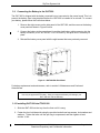
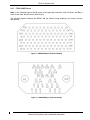
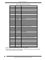
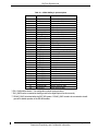

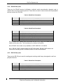
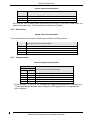


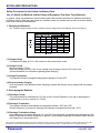


![SL24WP[VR.2]取扱説明書](http://vs1.manualzilla.com/store/data/006623024_2-ed288777da6f933750e135887cb48562-150x150.png)