1
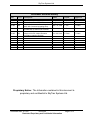
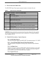
DSAT-200P System Operation
and TSO Antenna Installation Manual
DOC0268
Applies to DSAT-200P Mod None
Document Revision: 01.005
June 09, 2010
SkyTrac Systems Ltd.
200-170 Rutland Road
Kelowna, BC Canada
Tel. +1 250 765-2393
Fax +1 250 765-3767
Web: www.skytrac.ca
Email: [email protected]
Copyright © 2010 SkyTrac Systems Ltd.
All rights reserved.
SkyTrac Systems Ltd.
Document Revision History
Rev
ECO
Description
Date
Author
Approval
01.000
01.001
01.002
140
155
152
Mar 25, 08
July 7, 2008
Aug 30, 2008
T. Ratch
A. Parker
A. Parker
T. Ratch
T. Ratch
T. Ratch
01.003
240
Dec. 18, 2009
J. Van
T. Ratch
01.004
273
Feb. 19, 2010
G. Ross
T. Ratch
01.005
306
Initial draft
Updated battery reference to STS0032
Added references to STS0037
Removed all instances of Installing the
DSAT-200. Corrected operating temp.
Replaced references to STS0029 and
STS0028 with STS0039 and STS0040
Corrected all reference of operational
voltage to 32 VDC. Added activation
information regarding SkyWeb.
Jun. 09, 2010
G. Ross
T. Ratch
Proprietary Notice: The Information contained in this document is
proprietary and confidential to SkyTrac Systems Ltd.
Document Rev. 01.005
DOC0268
Restricted Proprietary and Confidential Information
Page ii of 12
SkyTrac Systems Ltd.
Warning
Changes or modifications not expressly approved by SkyTrac Systems Ltd. could void the
user’s authority to operate the equipment.
Warranty Information
SkyTrac Systems Ltd (STS) warrants this product to be free of defects in materials and
workmanship, and that the product meets or exceeds approved factory acceptance test
requirements. STS reserves the right to replace any warranted product at its sole discretion
during the warranty period.
The Model DSAT-200P Airborne Data/Position Communicator is under warranty for one
year from date of purchase. Failed units caused by defective parts, or workmanship should
be returned to:
SkyTrac Systems Ltd.
#200-170 Rutland Road North
Kelowna, B.C. Canada
V1X 3B2
Document Rev. 01.005
DOC0268
Restricted Proprietary and Confidential Information
Page iii of 12
SkyTrac Systems Ltd.
Table Of Contents
1
GENERAL .....................................................................................................................................1
1.1
1.2
1.3
1.4
INTRODUCTION ........................................................................................................................1
DESCRIPTION ..........................................................................................................................1
PURPOSE OF EQUIPMENT .......................................................................................................1
SYSTEM REQUIREMENTS ........................................................................................................1
2
CERTIFICATE OF CONFORMANCE ......................................................................................1
3
SPECIFICATIONS .......................................................................................................................2
3.1
PHYSICAL PROPERTIES ..........................................................................................................2
3.2
TECHNICAL SPECIFICATIONS ..................................................................................................2
3.2.1 GPS Receiver ...................................................................................................................2
3.2.2 DSAT-200 TSO Combination Antenna .........................................................................2
3.2.3 DSAT-200 Individual GPS and Iridium Antennas .......................................................2
3.2.4 Satellite Transceiver ........................................................................................................3
3.3
EMISSIONS COMPLIANCE ........................................................................................................3
4
AIRWORTHINESS LIMITATIONS ............................................................................................3
4.1
4.2
5
TSO ANTENNA INSTALLATION LIMITATIONS ...........................................................................3
OPERATION LIMITATIONS ........................................................................................................3
INSTALLATION INSTRUCTIONS ............................................................................................4
5.1
INSTALLATION REQUIREMENTS ...............................................................................................4
5.2
UNPACKING AND INSPECTING .................................................................................................4
5.2.1 Equipment Packing Log ..................................................................................................4
5.2.2 Installation Kit....................................................................................................................4
5.2.3 Installation Tasks..............................................................................................................4
5.3
ANTENNA INSTALLATION .........................................................................................................5
5.3.1 Portable Antenna Install ..................................................................................................5
5.3.2 Fixed Antenna Install .......................................................................................................5
6
PIN LOCATIONS AND CONNECTIONS .................................................................................7
6.1
7
DETAILED PIN DESCRIPTIONS – SYSTEM CONNECTOR .........................................................7
PROGRAMMING PORT .............................................................................................................8
7.1
REQUIRED HARDWARE ...........................................................................................................8
7.1.1 Determining the Correct Com Port ................................................................................8
7.2
FIRMWARE UPGRADE INSTRUCTIONS .....................................................................................9
8
POST INSTALLATION TESTS .................................................................................................9
8.1
8.2
FUNCTION TEST ......................................................................................................................9
EMI TEST ..............................................................................................................................10
Document Rev. 01.005
DOC0268
Restricted Proprietary and Confidential Information
Page iv of 12
SkyTrac Systems Ltd.
9
OPERATING INSTRUCTIONS................................................................................................10
9.1
9.2
UNIT ACTIVATION ..................................................................................................................10
OPERATING INSTRUCTIONS ..................................................................................................10
10 MAINTENANCE AND CONTINUED AIRWORTHINESS ...................................................11
10.1
10.2
CONTINUED AIRWORTHINESS ...............................................................................................11
MAINTENANCE INSTRUCTIONS ..............................................................................................11
11 APPENDIX A ..............................................................................................................................12
11.1
11.2
CAUSES OF RF INTERFERENCE ............................................................................................12
MITIGATION OF RF INTERFERENCE ......................................................................................12
Document Rev. 01.005
DOC0268
Restricted Proprietary and Confidential Information
Page v of 12
SkyTrac Systems Ltd.
1
1.1
GENERAL
Introduction
This publication provides technical information for the DSAT-200 Position/Data
Communicator, developed by SkyTrac Systems Ltd. The DSAT-200 provides position
reporting and messaging with global coverage in near real time.
1.2
Description
The DSAT-200 contains a GPS (Global Positioning System) receiver, an L-Band transceiver
specifically designed to communicate with the Iridium® satellite system, and a lithium ION
battery which powers the unit.
The DSAT-200 sends position data through a combination Iridium/GPS antenna which is
placed in a location that has a full view of the sky.
1.3
Purpose of Equipment
The DSAT-200P is the primary hardware component of a system designed to provide
satellite based data communications to any point in the world via Iridium® Low Earth Orbit
(LEO) satellites. The system includes the DSAT-200, the SkyTrac server network and
SkyTrac Systems Base Station Software. Please refer to the DSAT-200P User Guide
(DOC0305) for a more detailed description of the system and DSAT Functionality.
Operationally, the DSAT system can compliment flight following requirements for
commercial operators and provide vital position data and messaging services to those
operators conducting flight activities in remote areas.
1.4
System Requirements
The DSAT-200P package contains a combination GPS/Iridium antenna, or two portable
antennas. The antenna(s) must be placed in a location that has a clear view of the sky. The
DSAT-200P must receive GPS signals via the antenna to enable the determination of its
present position and communicate (send/transmit) with the Iridium® LEO satellite system.
In order to view position data, a Windows-based PC is required at the base location Please
see www.skytrac.ca for software options.
2
CERTIFICATE OF CONFORMANCE
The DSAT-200 Portable Mode has been approved on a SkyTrac Systems Certificate of
Conformance. This C of C certifies that the DSAT-200P has been inspected by SkyTrac
Systems Ltd. and has passed the DSAT-200P Quality Procedures Manual Final Assembly
Inspection Procedure to verify that the unit has been assembled in conformance with
SkyTrac Systems Ltd. approved drawings and documentation.
Document Rev. 01.005
DOC0268
Restricted Proprietary and Confidential Information
Page 1 of 12
SkyTrac Systems Ltd.
3
3.1
SPECIFICATIONS
Physical Properties
Operating Temperature
Size
Weight
Power Requirement
Mounting
3.2
-20ºC to +60ºC (-40°F to +1 31°F)
Caution: Refer to Battery System Operation and
Installation Manual (DOC0316) for restrictions on
battery operating limits.
H: 4.7 in / 119.4mm
W: 2.7in / 68.6mm
D: 7.6in / 193.0mm
2.5 lb / 1.1kg
Powered via STS Lithium ION Battery Pack
(STS0032 or STS0037) or by 10 to 32 VDC
(28 VDC Nominal).
Provision for attaching two mounting brackets
Technical Specifications
3.2.1 GPS Receiver
Receiving Method
Acquisition time
Position accuracy
Acceleration
12 Channel, Parallel Receiver
48 seconds after power up (cold start)
0.1 seconds for re-acquisition.
Less than 25 m
4 G max
3.2.2 DSAT-200 TSO Combination Antenna
Active L1 GPS/Passive Iridium Antenna, low profile, moulded radome.
Height:
0.721 in. (18.31 mm)
Length:
5.026 in. (127.66 mm)
Width:
2.0 in. (55.88 mm)
Weight:
8.0 oz (226 g)
Voltage:
3.0 to 28.0 VDC @ 50 mA max
Gain (GPS antenna): 32dB min
The Iridium® satellite serving a Short Burst Data call can literally be anywhere in orbit at a
given moment in time. For this reason, it is imperative that the antenna be mounted outside,
as high as possible, in a horizontal position on the aircraft, attempting to achieve a 360degree view of the sky with minimal obstructions.
3.2.3 DSAT-200 Individual GPS and Iridium Antennas
The DSAT-200P can also be operated with 2 portable antennas: one GPS antenna and one
Iridium antenna. The antennas have a Velcro base and must be attached a minimum 18
inches apart in a location that has a clear view of the sky.
Document Rev. 01.005
DOC0268
Restricted Proprietary and Confidential Information
Page 2 of 12
SkyTrac Systems Ltd.
Portable GPS Antenna:
Active L, low profile, moulded radome
H x W x D:
.5” x 1.3” x 1.7” (13.3 mm x 33.0 mm x 43.0mm)
Weight:
2.99 oz (85.0 g)
Voltage:
3.0 to 28.0 VDC @ 50 mA max
Power Handling:
1W
Portable Iridium Antenna:
Passive, low profile, moulded radome.
HxD:
0.57“ x 2.1“ (14.5 mm x 53.3 mm)
Weight:
3.7 oz (104.9 g)
Power Handling
28 W
3.2.4 Satellite Transceiver
Operating frequency
*Power consumption
1616 MHz to 1626.5 MHz
Transmit (max) 7W
*The DSAT-200P is not classified as “Equipment known to have a high potential for interference” in accordance with FAA
Policy No.: ASW-2001-01 dated April 25, 2002. Separate FADEC testing is not required for this installation.
3.3
Emissions Compliance
Entity
US FCC
US FCC
ETSI
Document Title
Title 47 Code of Federal Regulations
Title 47 Code of Federal Regulations 1997
Satellite Earth Stations and Systems (SES);
Harmonized EN for
Document Number
Section 15.109
Section 25.202
EN 301 441
The 9601 Iridium modem is certified under 47 CFR Part 25 as FCC ID: Q639601. It also
complies with Part 15 of the FCC Regulations and RSS-170 of the Canadian Radio
standards as IC: 4629A 9601.
4
4.1
AIRWORTHINESS LIMITATIONS
TSO Antenna Installation Limitations
The following installation regulations must be adhered to:
As per FAA Policy No.: ASW-2001-01 dated April 25, 2002, the antenna must not be
installed 0.5 meters or less from a FADEC system.
4.2
Operation Limitations
GPS Information provided by the DSAT-200P is not intended for navigational purposes.
Document Rev. 01.005
DOC0268
Restricted Proprietary and Confidential Information
Page 3 of 12
SkyTrac Systems Ltd.
When the Li-ION battery pack is installed in the DSAT-200P, additional operational
limitations apply. Refer to the Battery Pack System Operation and Installation Manual
(DOC0316 for STS0032 or DOC0238 for STS0037) for your battery type.
5
INSTALLATION INSTRUCTIONS
The DSAT-200P is a portable unit. The operator shall determine a secure location for the
DSAT-200P to ensure safety during all flight operations, including emergency landings.
5.1
Installation Requirements
When installing the TSO Antenna the installer shall have a working knowledge of aircraft
electronics installation, and be a holder of either an FAA Repairman’s Certificate or a
Transport Canada equivalent. All installations should meet the requirements of FAA
advisory circular AC43.13-1B.
5.2
Unpacking and Inspecting
5.2.1 Equipment Packing Log
Save the original shipping container in case of need for return due to damage or warranty
claims. Check that each item listed on the packing slip has been shipped in the container.
Verify and record the IMEI and the serial number of the DSAT-200P. This information is
required when contacting SkyTrac Systems to activate the satellite communications
services.
5.2.2 Installation Kit
An installation kit is available for the DSAT-200P for the individual antenna configuration as
well as for the combination antenna configuration.
5.2.3 Installation Tasks
IMPORTANT NOTE: Dependant on the time period between shipping of your unit and
the physical installation at your location firmware upgrades may become available.
It is recommended that you check with SkyTrac Systems client services to confirm if
any upgrades are available for your unit prior to proceeding with physical installation.
The main tasks for this installation are listed below:
1. Check the contents of the installation kit against the parts list on the Installation
Kit Package and verify that all components are included and not damaged during
shipping.
2. Install and charge the DSAT-200P LI-ION Battery Pack. Refer to STS0032 LIION Battery Pack and Install Manual (DOC0316) or STS0037 Battery Pack
System Operation and Installation Manual (DOC0238).
3. Determine the approximate location of the DSAT-200P and combination
GPS/Passive Iridium antenna or the two portable antennas.
Document Rev. 01.005
DOC0268
Restricted Proprietary and Confidential Information
Page 4 of 12
SkyTrac Systems Ltd.
Note:
Factors to be considered to determine install location include
maximum antenna coax lengths and minimum distance between
existing GPS antennas and the DSAT-200P antennas.
Note:
If DSAT-200P is to be installed near an active INMARSAT
terminal or if the aircraft that the DSAT-200P is installed in
operates near an active INMARSAT terminal, please see
Appendix A.
Note:
If installing the separate GPS and Iridium antennas, the
minimum separation distance requirement is 18 inches.
4. Secure the DSAT-200P.
5. Mount the antenna(s).
6. Route the coax cables for Iridium and GPS antenna signals to the DSAT-200P
combination antenna or separate portable antennas.
7. If desired, connect the DSAT-200P System connector to 10 to 32 volts DC (IE via
cigarette lighter)
5.3
Antenna Installation
5.3.1 Portable Antenna Install
The portable DSAT-200P installation will use a portable active L1 GPS antenna STS0039
and a separate passive Iridium antenna STS0040.
The two antennas must be installed at least 18 inches from one another in a location that
has a clear view of the sky. SkyTrac Systems also recommends that the cable length for
each cable be no more than the provided 7.5 feet.
The GPS antenna uses a BNC connector to connect to the DSAT-200P.
The Iridium antenna uses a TNC connector to connect to the DSAT-200P.
5.3.2 Fixed Antenna Install
The DSAT-200P can also be utilized with a combination, active L1 GPS/Passive low profile,
molded radome, Iridium antenna (P/N:STS0021). This recommended system antenna is
only available directly from SkyTrac Systems Ltd and is permanently installed on the outside
of the aircraft. Please contact SkyTrac Systems to discuss the feasibility of using an
alternate antenna if required.
The combination antenna must be installed at least three feet away from any other
GPS antenna. It is imperative that the antenna be mounted outside, as high as possible
and in a horizontal position on the aircraft, attempting to achieve a 360-degree view of the
sky with minimal obstructions.
Document Rev. 01.005
DOC0268
Restricted Proprietary and Confidential Information
Page 5 of 12
SkyTrac Systems Ltd.
IMPORTANT NOTE: This antenna uses an SMA and a BNC connector for the GPS
jack and TNC connectors for the L-Band or Iridium jack. Immediate damage will occur
to the DSAT-200P if either cable is connected to the wrong jack.
The use of RG-400 low-loss coaxial cable restricts the maximum length of the cable to 18 ft.
If a longer run is required, use lower loss coax cable like ECS 310801, 311601, 311501, or
311201 and refer to manufacturers’ specifications for attenuation at 1.6 GHz. Attenuation of
equal or less than 3dB is required. The bond between the airframe and the antenna needs
to be 10 milliohms or less.
Prepare the mounting location by drilling holes in the aircraft skin or through a mounting
plate. Use a doubler plate of 4 x 6 inches if antenna is installed on a non-metallic aircraft
surface to create a ground plane. The plate must have an electrical connection to the
antenna ground.
Installation of an antenna on the aircraft should be performed only as defined by the aircraft
manufacturer or in accordance with TC or FAA approved engineering data. Special caution
must be observed when installing antennae in pressurized aircraft.
Note: The combination antenna includes a rubber seal that must be properly
installed into the groove on the underside of the antenna prior to mounting the
antenna. This seal acts as an environmental seal from the outside atmosphere. Any
connections that are not protected from the outside atmosphere by the rubber
antenna seal should have an environmental seal applied to them during installation.
Document Rev. 01.005
DOC0268
Restricted Proprietary and Confidential Information
Page 6 of 12
SkyTrac Systems Ltd.
6
PIN LOCATIONS AND CONNECTIONS
The DSAT-200P has a 25 pin system connector located on the back of the unit.
Table 4-1
System Connector - Pin Description
25 Pin System Connector – DSAT-200 Portable Mode
Pin #
Description
1
2
+28 VDC Main Power In
Current Sinking Digital Output #1 (Data Delay Indication)
3
Unit Mode Select
4
5
Signal Ground (Dig I/O only)
Reserved
6
Aux Power Output (9505A, etc)
7
Aux Power Output Ground Return
8 - 13
Reserved for Future Use – Do Not Connect, Do not connect to ground.
14
Ground (Power)
15- 25
Reserved for Future Use – Do Not Connect, Do not connect to ground.
CAUTION: Please note that the ground pins should only be configured for their specified
use. Any other configuration may cause the unit to malfunction, or in extreme conditions
cause damage to the unit.
6.1
Detailed Pin Descriptions – System Connector
Pin 1 +28 VDC Main Power In
This is the main power supply to the DSAT-200P. The operating range is 10 - 32VDC
Pin 2 – Current Sinking Digital Output #1 (Data Delay Indicator)
This output has been configured as a sinking output and can sink up to 200mA at
32VDC
Pin 3 - Unit Mode Select
Digital I/O - This pin is used by the DSAT-200P to determine whether or not to send
position reports when mains power is applied. If this pin is connected to Digital I/O
ground, position reports will be sent when mains is applied.
Pin 4 - Digital I/O Ground
Document Rev. 01.005
DOC0268
Restricted Proprietary and Confidential Information
Page 7 of 12
SkyTrac Systems Ltd.
Digital I/O ground only. This is not a power ground pin. Connect Mode Select to this
pin to activate it.
Pin 5 - Reserved
Pin 6 - Auxiliary Power Output
This Output is designed to power the Iridium 9505 Handset (STS0024). This output
can be enabled / disabled via DSAT-200P firmware configuration. Attempting to
charge the portable handset when the DSAT-200P is operating on battery will drain
the DSAT battery very quickly.
Pin 7 - Auxiliary Power Output Ground Return
This is the ground return for Pin 6 only. Do not use for any other application and do
not connect to Power Ground.
Pin 8 - 13 – No Connect
These pins are reserved for future use and not supported at this time. – Do not
connect, do not connect to ground.
Pin 14 - Ground (Power)
This is the power ground connection for the DSAT-200P.
Pins 15 – 25 – No Connect
These pins are reserved for future use and not supported at this time. – Do not
connect, do not connect to ground.
7
PROGRAMMING PORT
The DSAT-200P will be shipped with the newest version of firmware. If firmware updates
are required, the USB programming port is used to install the revised firmware in the DSAT200P.
7.1
Required Hardware
Laptop or PC with available USB port
XP Operating System
Type A to Type B USB connector
7.1.1 Determining the Correct Com Port
Connect the DSAT-200P to the computer by inserting the Type A end of the cable to the
computer and the Type B end of the cable to the DSAT-200P.
For operating systems of Windows XP and higher, Windows automatically detects the
DSAT-200P and creates a virtual port to communicate with the DSAT-200P. In order to
communicate with the DSAT, the operator will need to know which COM port number
Windows has assigned to the DSAT. Each DSAT will be assigned a different COM port by
Windows.
Document Rev. 01.005
DOC0268
Restricted Proprietary and Confidential Information
Page 8 of 12
SkyTrac Systems Ltd.
Once the cable has been connected from the PC to the DSAT-200P, open Device Manager
on the PC by clicking:
Start -> Settings –> Control Panel –> Administrative Tools –> Computer Management
Select Device Manager from the column on the left, and then expand the Ports section in
the right column. The com port that the USB cable is using will be listed there. Enter that
port number as part of Step 5 of the firmware upgrade instructions listed below.
Please Note: The com port number will be the same every time that particular DSAT is
connected to, but if multiple DSAT’s require firmware upgrades, each DSAT will be assigned
a different com port number. COM port numbers will also vary from computer to computer.
7.2
Firmware Upgrade Instructions
Please note: The DSAT-200P will not send position reports while in programming mode
Please note: The DSAT-200P will not enter programming mode when the DSAT is
operating in the DSAT Emergency mode.
1. Download the new firmware version from the SkyTrac website (www.skytrac.ca) to
the computer. This firmware is called DSAT-200-Rxx-xx-xx.zip (where xx.xx.xx is the
Firmware version included in the zip file).
2. Extract the DSAT-200-Rxx-xx-xx.zip file to a directory on the Windows PC.
3. Connect the Type A connector of the USB Cable to the Windows PC. Connect the
other end of the USB Cable to the DSAT-200P.
4. Apply power to the DSAT-200P.
5. Press and hold the PROG button for 5 seconds – the programming LED light should
go solid.
6. Run the firmware upgrade batch file by double-clicking the DSAT-200-xx.xx.xxUpload.bat file that was extracted to the directory on the Windows PC
7. Enter the appropriate com port as described above.
8. Type “y” and press Enter to run the upgrade program. It will take approximately one
minute to install the upgrade.
9. When complete, press any key to close the DOS window.
10. Remove the cable from the DSAT and the PC.
11. Reset the DSAT by pressing and holding the POSN/PWR button or by power cycling
mains power.
12. When the DSAT resets, the display will show the current firmware version. Ensure it
matches the version that was just installed.
8
8.1
POST INSTALLATION TESTS
Function Test
The avionics installer must perform this test immediately after installation.
a) Move aircraft to a location with unrestricted visibility of the sky.
Document Rev. 01.005
DOC0268
Restricted Proprietary and Confidential Information
Page 9 of 12
SkyTrac Systems Ltd.
b) Turn the unit on by pressing the Power button and holding for five seconds.
c) Test proper GPS function. An acceptable method for testing GPS function is to
use STS flight following software to check if a valid position and GPS time is
reported for the installed DSAT-200P.
d) Access the System menu by pressing the Menu button. Go through the Com
Diag menu options to ensure GPS and MDM signal are good.
8.2
EMI Test
As with any electronic equipment, portable or installed, it is ultimately up to the user to
ensure there is no interference with existing aircraft electronic systems.
Please reference EMI/RFI Test Template DOC0302 Rev 01.002 or latest revision for testing
procedures.
The purpose of this test report is to verify that the operation of the DSAT-200P does not
interfere with basic aircraft systems and avionics.
Most of the EMI tests can be accomplished on the ground. In some cases flight-testing is
required or is easier. If the aircraft is approved for IFR operations, then it is mandatory that
interference between the DSAT-200P and the approach aids be checked in-flight.
The existing on-board GPS should be operational and navigating with at least the minimum
compliment of satellites. The VHF Comm. should be set to commonly used frequencies with
the squelch open. VOR/DME receivers should be selected for display. If possible, set up a
DME ramp test set on the frequencies indicated and adjust the output until the flags are out
of view. The transponder and encoder should be monitored with ramp test equipment. Set
the output of the transponder test set to 3db above the output necessary to achieve 90%
reply. If possible set the ADF to a nearby navigation station.
9
9.1
OPERATING INSTRUCTIONS
Unit Activation
To activate your unit, log into SkyWeb and proceed to the Hardware Management Section.
Please note that charges will currently occur at the factory default reporting interval of 2
minutes. Changing the position reporting interval can be achieved through the Hardware
Management section of SkyWeb. For help, contact SkyTrac Client Services Dept. at 250765-2393 or email [email protected].
9.2
Operating Instructions
The unit may be powered on by pressing the POSN / PWR button and holding for five
seconds, or by applying mains power.
Document Rev. 01.005
DOC0268
Restricted Proprietary and Confidential Information
Page 10 of 12
SkyTrac Systems Ltd.
To turn the unit off, remove mains power or press and hold the POSN/PWR button for five
seconds.
If operating on Mains Power pressing the POSN/PWR button and hold for five seconds will
power cycle the unit instead of powering down the unit. Remove Mains to power down the
unit.
Please see the DSAT-200P User Manual (DOC0305) for full operating instructions.
10 MAINTENANCE AND CONTINUED AIRWORTHINESS
10.1
Continued Airworthiness
The DSAT-200P does not require any maintenance if installed in an actively flying aircraft
other than battery pack maintenance.
Please refer to the System Operation and Installation Manual (DOC0316 or DOC0238) for
your battery pack for additional important Continued Airworthiness information.
10.2 Maintenance Instructions
The DSAT-200P does not require any maintenance other than regular care of the battery
pack. Please see STS0032 LI-ION Battery Pack and Install Manual (DOC0316) or STS0037
Battery Pack System Operation and Installation Manual (DOC0238) for detailed information.
Document Rev. 01.005
DOC0268
Restricted Proprietary and Confidential Information
Page 11 of 12
SkyTrac Systems Ltd.
11 APPENDIX A
11.1 Causes of RF Interference
Some subscribers have contacted Iridium® regarding the loss of signal quality when they
operate their equipment near active INMARSAT terminals.
The power with which INMARSAT units transmit can overpower the Iridium® unit’s ability to
properly maintain a quality connection with the Iridium® satellite constellation. INMARSAT
terminals are often found in the same locations as Iridium® subscribers’, generally airports
and harbors (especially aboard ships).
In relation to the Iridium® unit’s antenna, the location of the INMARSAT unit’s antenna plays
a significant role in determining the degree of signal degradation an Iridium® subscriber will
experience. All Iridium® units are susceptible to this interference, regardless of the type of
antenna being used.
Susceptibility to interference from an INMARSAT terminal applies to all Iridium® end-user
products (9500 and 9505 equipment, including the L-Band Transceiver (LBT), which is
contained in products developed by SkyTrac Systems). Generally speaking, an Iridium® unit
located within 15 to 45 meters (50 to 150 feet, respectively) of an operating INMARSAT
mini-M or Standard-C terminal, will likely experience interruption in the unit’s performance.
Other sources of RF interference such as Globalstar® units, radar devices and broadcast
stations can cause interference for Iridium® units, but usually are not encountered as
frequently as INMARSAT terminals.
11.2 Mitigation of RF Interference
Degradation of service due to RF interference to the Iridium® unit can be significantly
improved by performing either or both of the following actions:
a) Increasing the distance and moving the Iridium® antenna off axis from the source of the
interference, or
b) Using an external band pass filter and an external antenna.
In determining the optimal location for mounting an external Iridium® antenna in a location
where INMARSAT antennae are also located, be certain that the Iridium® antenna is
mounted to the side or behind the INMARSAT antenna, as well as above or below it. Also
note that the length of the feed line (the cable running from the Iridium® unit to the antenna)
plays an important role in the performance of the unit.
Document Rev. 01.005
DOC0268
Restricted Proprietary and Confidential Information
Page 12 of 12