1
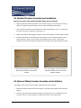
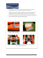
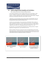
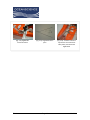
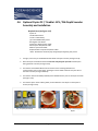
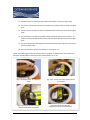
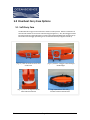
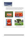
The Oceanscience Group
Riverboat User Guide
v1.2.0
Riverboat
Page 1
8/31/2011
Table of Contents
Section
Introduction
2.0
Riverboat Specifications
3.0
Order Codes
3.1
Riverboat Assembly and Installation
4.0
ADCP Installation
4.1
Safety Cable Assembly and Installation
4.2
Standard Crossbar Assembly and Installation
4.3
Sliding Crossbar Assembly and Installation
4.4
Rigid Bridle Assembly and Installation
4.5
Oyster PE / Trimble I-GPS / P66 Depth Sounder Assembly and Installation
4.6
Riverboat Carry Case Options
5.0
Soft Case
5.1
ATA Case
5.2
Riverboat Warranty
6.0
Addendum
7.0
Sentinel ADCP Mounting Bracket Assembly Instructions
Riverboat
Page 2
7.1
8/31/2011
2.0 Introduction
Congratulations on your recent purchase of the Oceanscience Riverboat.
The Oceanscience Riverboat is the world-wide benchmark for acoustic Doppler current profiling for
discharge measurements. The Riverboat and ADCP combination has drastically reduced discharge
measurement time and labor all over the world. This rugged, stable, corrosion-resistant tethered boat
makes safe, easy measurements of discharge with ADCPs. Relatively slow and fast flowing water can be
handled with ease, and available radio communications options complete with the total discharge
monitoring package.
The Oceanscience Riverboat has gathered data at water velocities over 15 fps (4.5m/s). The bow flare
trimaran hull design prevents the boat from nose-diving and maintains instrument orientation by
reducing pitch and roll in varied flows. The central hull reduces drag by a factor of 2-4 over catamaran
designs making the Riverboat capable of operation in a range of water velocities, maximizing the data
collection potential of the ADCP.
Made of unbreakable polyethylene, the Riverboat is strong and robust to cope with the worst deployment
conditions. The standard boat fits an 8” TRDI Rio Grande ADCP and is configured for use of Oceanscience
single-channel spread spectrum radio modems. All required cabling, batteries, and antennae are included
for easy plug-and-play operation. Electronics are located below deck in a watertight compartment. Other
Doppler profilers of 8” diameter or less may be used with adaptor mounts. The Riverboat can be supplied
with a pigtailed wiring harness for user radio installation.
Optional equipment includes DGPS location and data handling options such as the powerful Oceanscience
Oyster PE2 on-board computer or Hydrolink radio modems, to make the Riverboat the most versatile
tethered survey platform available. Select the Oceanscience Sliding Crossbar option to easily disassemble
the Riverboat for transportation in the available hard or soft cases.
Riverboat
Page 3
8/31/2011
3.0 Riverboat Specifications
RIVERBOAT SPECIFICATIONS
Typical Measurement Water Velocity
2 - 10 fps (.6 - 3 m/s)
Maximum Water Velocity
15 fps (4.6 m/s)
Center Hull Length
48” (121cm)
Overall Width (Assembled)
32” (81cm)
Crossbar Material
Anodized Aluminum
Hull Material
Molded Unbreakable Polyethylene
Weight
15 lbs. (7kg)
Hardware
Aluminum
Safety Lines
Stainless Steel
Fasteners
Stainless Steel
Fin Configuration
Kick-up Fins
ADCP Size
8”
3.1 Riverboat Order Codes
RBHL – Riverboat for Hydrolink radios
RBPT – Riverboat with pigtailed wiring harness
SCBR – Sliding Crossbar
SCAS – Soft transportation case
HCAS – Aluminum ATA transportation case
RBFK – Riverboat Fin Kit
Riverboat
Page 4
8/31/2011
4.0 Riverboat Assembly and Installation
4.1 ADCP Installation
1.
With the ADCP looking downward, sitting on its cap, install the ¼-20 x 3” mounting studs.
Insert the stud from above and install a lock washer and standard nut on the bottom, leaving
no more thread than necessary protruding from the bottom of the nut. (See Figure 4.1)
2.
Install a hex nut from the top, using wrenches provided to snug both nuts against the
instrument flange. This will leave about ¾” of thread protruding upwards to pass through
the Riverboat crossbar and receive the wing nuts and lock washers.
3.
Place the crossbar and hulls over the ADCP so that the threaded rods extend through the
crossbar holes. Fasten in place with the wing nuts and lock washers, using the instrument
safety cable in place of the fourth wing nut (see safety cable instructions, section 4.2).
Electronics Compartment
Figure 2 shows a sample transceiver / battery configuration. See your Hydrolink Transceiver
manual for specific instructions about installing your electronics equipment if this pertains to
your unit.
(Fig. 4.1) Mounting studs installed
Riverboat
(Fig. 4.2) Sample transceiver / battery configuration
Page 5
8/31/2011
4.2 Safety Cable Assembly and Installation
1.
The safety cable provides a vital link from the ADCP to the tow line. Use the eye nut at one
end of the safety cable to secure one of the forward ADCP mounting studs to the Riverboat
crossbar (see Figure 4.3).
2.
Attach the other end of the safety cable to the carabiner as shown (see Figures 4.4 and 4.5).
(Fig. 4.3) Safety cable eye nut placement
(Fig. 4.4) Standard crossbar with wire rope
bridle and instrument safety cable
Riverboat
(Fig. 4.5) Safety cable, wire rope bridle,
and carabiner ready for tow line
Page 6
8/31/2011
4.3 Standard Crossbar Assembly and Installation
(Proceed to section 4.4 if optional Sliding Crossbar was purchased)
1.
Begin by attaching the Wire Rope Bridle to the crossbar using the ¼-20 nylock nuts as shown in
Figure 4.6. Align the eyes horizontally so they do not protrude below the crossbar.
2.
Next, attach the crossbar and strap handles to the main hull using the ¼-20 x 1 ¼” screws with
flat washer above the strap grommet (see figure 4.7).
3.
Attach the crossbar to the outriggers using the ¼-20 x1” buttonhead screws with fender washers.
4.
Install the kick-up fins on the inside of the hulls using the ¼-20 x ¾” buttonhead patch screws
with lock washers. When you are ready to put the Riverboat in the water, rotate the fins
downward into the desired position and tighten the retaining screws with the provided hex key.
(Fig. 4.6) Wire Rope Bridle and Instrument
Safety Cable attached to the Standard
Crossbar
(Fig. 4.7) Outrigger, main hull, and strap
handles assembled, with fins mounted
between the hulls
4.4 Optional Sliding Crossbar Assembly and Installation
The Sliding Crossbar enables quick assembly and disassembly of the Riverboat.
1.
Mount the crossbar sections to the hulls using the ¼-20 x 5/8” buttonhead cap screws and flat
washers.
2.
Install the wire rope harness eyebolts through the horizontal holes on the outriggers forward
crossbar members. Lock the eyebolts into place with the lock nut (see figure 4.8).
Riverboat
Page 7
8/31/2011
3.
Slide the outriggers into the main hull, align the retaining pin holes, install the two cabled
retaining pins in the aft holes, and tighten the thumbscrews (see figure 4.10).
4.
Install the kick-up fins on the inside of the hulls using the ¼-20 x ¾” button head patch screws
with lock washers. When you are ready to put the Riverboat in the water, rotate the fins
downward into the desired position and tighten the retaining screws with the provided hex key.
5.
If you are using our Soft Case or our ATA case (see figure 4.9), your Riverboat can be stored with
your ADCP mounted and your transceiver and battery installed.
(Fig. 4.8) Wire Rope Harness eyebolt
with lock nut installed on outrigger
(Fig. 4.9) Riverboat in storage / transport case
(Fig. 4.10) Insert the outrigger crossbar parts into the main hull, align, install the retaining
pins, and tighten the thumb turns
Riverboat
Page 8
8/31/2011
4.5 Optional Rigid Bridle Assembly and Installation
(Can only be used with the Riverboat Sliding Crossbar)
In rare situations, Riverboat users want to deploy their boats very near to a bridge. In these
cases, the standard wire rope harness included with your Riverboat tends to pull the bow
upwards. The optional rigid bridle provides a fixed attachment point above the boat. The higher
attachment point helps keep the bow down and the ADCP in the water.
In higher flows, care must be taken to make sure that the bow is not pushed down too much.
This can cause submersion of the boat which increases drag and could cause loss of the boat.
The rigid bridle also makes the boat more difficult to turn.
Use of the correct towing angle is critical to performance and equipment safety. Ideally, the
tether and rigid bridle are collinear. If the bow still pitches up too much, a very slight negative
towing angle on the rigid bridle may be used. Extreme care should be taken as a large negative
angle may cause the bow to dive, submerging the Riverboat (see figures 4.11 - 4.13).
For these reasons, we recommend using the rigid bridle only in relatively low flows. Using the
rigid bridle in flows greater than 1 m/s is done at the user’s risk.
Whenever possible, Oceanscience recommends removal of the rigid bridle and use of the wire
rope harness by itself. The rigid bridle detaches easily by removing the shoulder bolts at the base
of the uprights (see figure 14). Be sure to secure the retaining pins with their cable leashes with
storing the loose parts for the Rigid Bridle (see figures 4.15 and 4.16).
(Fig. 4.11) Preferred towing
angle. Tether and bridle are
collinear.
Riverboat
(Fig. 4.12) Positive towing
angle. Acceptable
Page 9
(Fig. 4.13) Negative towing
angle. May submerge the boat,
causing severe drag and
possible loss of the boat
8/31/2011
(Fig. 4.14) Rigid Bridle
connection detail
Riverboat
(Fig. 4.15) Rigid Bridle loose
parts
Page 10
(Fig. 4.16) Carabiner with wire
rope harness and instrument
safety cable, attached to the
Rigid Bridle
8/31/2011
4.6 Optional Oyster PE / Trimble I-GPS / P66 Depth Sounder
Assembly and Installation
Required Parts (see figure 4.17)
Oyster PE
Trimble GPS Receiver
12 Volt 7.2 SLA Battery
(3) 12 Volt NiMH Battery Packs
Rectangular Heat Shield
Oyster PE to Battery-Power Cable
GPS to Oyster-Data/Power Cable
ADCP to Oyster-Data Cable
Depth Sounder to Oyster-Data/Power Cable
*Note: All batteries should be fully charged before beginning this process
1.
To begin, secure the pre-installed Riverboat cables with tape as shown (see figure 4.18).
2.
Place the Oyster PE inside the boat with the heat sink facing the port side and data ports
facing upwards as shown (see figure 4.19).
3.
Connect the three labeled DB-9 serial connectors to the matching labeled serial
communication ports on the Oyster, allowing the excess cable to fall over the port side of
the boat as shown (see figure 4444.19).
4.
Connect the Antenna RF cable (installed) to the labeled antenna port on the Oyster as shown
(see figure 4.19).
5.
Connect the Oyster Power Cable (yellow) to the labeled 12 V DC IN port on the Oyster as
shown (see figure 4.19).
(Fig. 4.17) Required Parts
Riverboat
(Fig. 4.18) Pre-installed Cables
Page 11
(Fig. 4.19) Connecting the
Oyster
8/31/2011
6.
Place the Trimble GPS Receiver into the boat with the flat side facing the Oyster. Then
connect the (black) LEMO Connecter (Comm. 1) into the port on the GPS Receiver. Note the
red dots for alignment as show (see figure 4.20).
7.
Connect the Internal GPS Ant. Cable (installed) to the Port on the GPS Receiver (see figure
4.20).
8.
Connect the Depth Sounder Data Cable (Comm. 2 yellow) to the installed Internal Depth
Sounder Cable (stern starboard side, yellow) as shown (see figure 4.21).
9.
Connect the Oyster to the ADCP Data Cable (Comm. 3) to the Internal ADCP Cable as shown
(see figure 4.22).
(Fig. 4.20) Connection the GPS
(Fig. 4.21) Connecting the
Depth Sounder
(Fig. 4.22) Connecting the ADCP
Cable
10. Carefully position the Oyster PE and GPS Receiver into the hull cavity; ensure that the three
white instrument power leads are still outside of the boat as shown (see figure 4.23).
11. Position the Large 12 volt battery and connect the leads accordingly as shown (see figure
4.24).
12. Position the Rectangular Heat Shield between the GPS Receiver and Oyster as shown (see
figure 4.25).
(Fig. 4.23) Position Oyster PE
and GPS receiver into hull
Riverboat
(Fig. 4.24) Position and connect
12 volt battery
Page 12
(Fig. 4.25) Position Heat Shield
between GPS and Oyster
8/31/2011
13. Position the three 12 volt battery packs with leads forward as shown (see figure 4.26).
14. Connect the instrument power leads to the batteries (no specific order) as shown (see figure
4.27).
15. Position all access wiring in the space provided behind the instruments as shown (see figure
4.28).
16. The white battery connections and ADCP cable should remain above the instruments. All
cables and wiring should be positioned away from the Oyster Heat Sink as shown (see figure
4.29).
17. The Oyster PE Heat Sink should always be positioned facing the port side of the hull cavity as
shown (see figure 4.29).
18. Place the deck lid on tightly; the Riverboat is now ready for use.
*NOTE: the on/off toggle switch only controls power to the ADCP. To power off the other instruments,
disconnect the white battery connections when the Riverboat is not in use.
(Fig. 4.26) Position three 12 volt battery
packs
(Fig. 4.27) Connect instrument power leads to
the batteries
(Fig. 4.29) Position all cables and
wiring away from the Oyster Heat Sink
(Fig. 4.28) Position all access wiring in
the space behind the instruments
Riverboat
Page 13
8/31/2011
5.0 Riverboat Carry Case Options
5.1 Soft Carry Case
The Riverboat fits snugly into the Soft Case as shown in these pictures. Note the orientation of
the hulls with all bows to the narrow end of the bag (see figure 5.1). Also, the outriggers should
be nested inside the rigid bridle flanges as shown inside the Rigid Bridle flange (see figure 35.2).
Be mindful of the outrigger positioning so not to disturb antennae (see figure 5.3 and 5.4).
(Fig. 5.1) Bows of all hull at narrow end
of Soft Case
(Fig. 5.2) Nest the outriggers inside the Rigid
Bridle flanges
(Fig. 5.4) Riverboat with Sliding
Crossbar stowed in the Soft Case
(Fig. 5.3) Correct arrangement of the
hulls inside the Soft Case
Riverboat
Page 14
8/31/2011
5.2 ATA Hard Carry Case
The Riverboat fits snugly into the ATA Case as shown in these pictures. Note the orientation of
the hulls with all bows to the one end of the case (see figure 5.5). Also, the outriggers should be
nested inside the rigid bridle flanges as shown inside the Rigid Bridle flange (see figure 5.6). Be
mindful of the outrigger positioning so not to disturb antennae (see figure 5.7 and 5.8).
(Fig. 5.5) Bows of all hull at one end of
ATA Style Case
(Fig. 5.6) Nest the outriggers inside the Rigid
Bridle flanges
(Fig. 5.8) Riverboat with Sliding
Crossbar stowed in the ATA Case
(Fig. 5.7) Correct arrangement of the
hulls inside the ATA Case
Riverboat
Page 15
8/31/2011
6.0 Riverboat Warranty
The Oceanscience Group, Ltd makes every effort to assure that its products meet the highest
quality, reliability and durability standards and warrants to the original purchaser or original
purchasing agency that each Riverboat be free from defects in materials or workmanship for a
period of one year from date of shipment.
Polyethylene Riverboat hulls are warranted free from manufacturing defects for three years from
date of shipment.
Warranty does not apply to defects due directly or indirectly to misuse, negligence or accidents,
repairs or alterations outside of our facilities, use of the Riverboat for purposes other than river
discharge measurements, or use with instruments weighing more than 25 lbs.
Oceanscience is not responsible for loss of boat, instruments, damage to property, injury or
death associate with the use of any of its products or products that may be included or used with
Oceanscience products.
Oceanscience does not warrant third party products sold by Oceanscience. These may include
GPS, depth sounders and other ancillary equipment.
All warranty services are FOB Oceanscience’s facility in Oceanside, CA.
Riverboat
Page 16
8/31/2011
7.0 Addendum
7.1 Sentinel ADCP Mounting Bracket Assembly Instructions
1.
Position the Sentinel ADCP mounting bracket over the four holes of the crossbar as shown (see
figure 7.1).
2.
Using the strap handle hardware bag 6100026, place the strap handle grommets over the
sentinel mount feel. Then place a ¼” flat washer over the grommet, and attach with the 1 ¼”
button head screws as shown (see figure 7.2).
(Fig. 7.1) Position mounting bracket over
the four holes of the crossbar
Riverboat
(Fig. 7.2) Place strap handle grommets
over mount feet and attach
Page 17
8/31/2011


![RessqM, Enhanced Version of RESSQ [Javandel et al., 1984]](http://vs1.manualzilla.com/store/data/005674408_1-e8a4b9f66c80cdc83d847a710e5b4b1f-150x150.png)