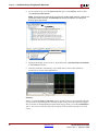
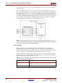
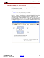
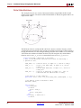
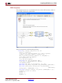
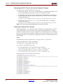
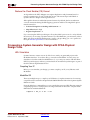
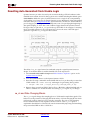
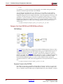
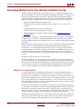
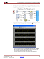
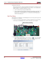
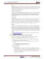
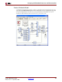
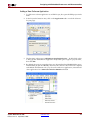
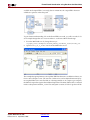
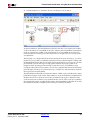
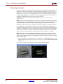
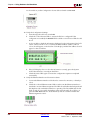
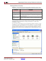
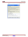
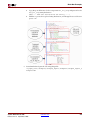
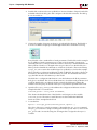
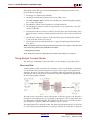
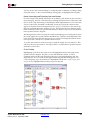
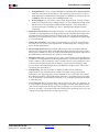
1
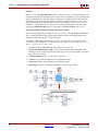
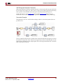
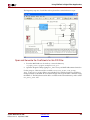
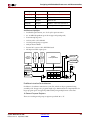
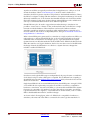
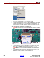
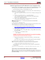
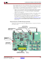
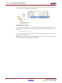
R
Installing Your Hardware Co-Simulation Board
Installing an ML402 Board for JTAG Hardware Co-Simulation
The following procedure describes how to install and setup the hardware and software
required to run JTAG Hardware Co-Simulation on an ML402 board.
Assemble the Required Hardware
1.
2.
Xilinx Virtex™-4 SX ML402 Platform which includes the following:
a.
Virtex-4 ML402 board
b.
5V Power Supply bundled with the ML402 kit
c.
CompactFlash Card
You also need the following items on hand:
a.
Xilinx Parallel Cable IV with associated Power Jack splitter cable or Xilinx
Platform USB Cable and a 14-pin ribbon cable.
b.
CompactFlash Reader for the PC.
Install the Software on the Host PC
•
System Generator version as specified in the current System Generator Release Notes.
•
Xilinx ISE™ Software version as specified in the current System Generator Release
Notes.
Setup the ML402 Board
The figure below illustrates the ML402 components of interest in this JTAG setup
procedure:
FPGA & CPU
Debug Port
1.
Position the ML402 board so the Virtex™-4 and Xilinx logos are oriented near the top
edge of the board.
2.
Make sure the power switch, located in the upper-right corner of the board, is in the
OFF position.
System Generator for DSP
Release 10.1.3 September, 2008
www.xilinx.com
253