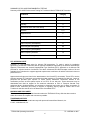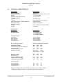
1
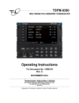
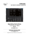
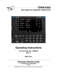
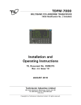
TDFM-9100
MULTIBAND P25 AIRBORNE TRANSCEIVER
Operating Instructions
TiL Document No. 13RE482
Rev. N/C
November 2014
Technisonic Industries Limited
240 Traders Boulevard, Mississauga, Ontario L4Z 1W7
Tel: (905) 890-2113 Fax: (905) 890-5338
www.til.ca
Copyright 2012 by Technisonic Industries Limited. All rights reserved.
ii
REVISION HISTORY
[ 13RE482 ]
REV
SECTION
- PAGE -
DESCRIPTION
iii
DATE
Edited by
iv
NOTES
CAUTION STATIC SENSITIVE !
This unit contains static sensitive devices. Wear a grounded wrist strap and/or conductive gloves
when handling printed circuit boards.
FCC COMPLIANCE INFORMATION
This device complies with Part 15 of the FCC Rules. Operation is subject to the following two conditions:
(1) this device may not cause harmful interference and (2) this device must accept any interference
received, including interference that may cause undesired operation.
WARNING: For compliance with FCC RF Exposure Requirements the mobile transmitter
antenna installation shall comply with the following two conditions:
1. The transmitter antenna gain shall not exceed 3 dBi.
2. The transmitter antennas shall be located outside of a vehicle and must not be co-located (kept at
a separation distance of more than 20cm from each other when installed). Also they must be
installed in such a way that they always maintain a separation distance of more than 90cm from
any person during operation.
NOTE: This equipment has been tested and found to comply with the limits for a Class A digital device,
pursuant to Part 15 of the FCC Rules. These limits are designed to provide reasonable protection against
harmful interference when the equipment is operated in a commercial environment. This equipment
generates, uses, and can radiate radio frequency energy and, if not installed and used in accordance with
the instruction manual, may cause harmful interference to radio communications. Operation of this
equipment in a residential area is likely to cause harmful interference, in which case the user will be
required to correct the interference at his/her own expense.
WARNING AND DISCLAIMER
Changes or modifications not expressly approved by Technisonic Industries could void the user’s
authority to operate the equipment.
This manual is designed to provide information about the TDFM-9100. Every effort has been made to
make this manual as complete and accurate as possible.
WARRANTY INFORMATION
The Model TDFM-9000 Transceiver is under warranty for one year from date of purchase.
Failed units caused by defective parts, or workmanship should be returned to:
Technisonic Industries Limited
240 Traders Boulevard
Mississauga, Ontario L4Z 1W7
Tel: (905) 890-2113
Fax: (905) 890-5338
TDFM-9100 Operating Instructions
TiL 13RE482 rev N/C
v
SUMMARY OF DO-160G ENVIRONMENTAL TESTING
Summary of DO-160G Environmental Testing for Technisonic Model TDFM-9100 Transceiver:
Conditions
Category
Temperature and Altitude
A2, B1, C4, D1
Temperature Variation
B
Humidity
A
Operational shock and Crash Safety
A
Vibration
S, U
Magnetic Effect
Z
Power Input
B
Voltage Spike
B
Audio Frequency Susceptibility
B
Induced Signal Susceptibility
AC
Radio Frequency Susceptibility
T
Radio Frequency Emission
M
Electrostatic Discharge
A
STC APPROVAL NOTE
Presently, no TSO standard exists for airborne FM transceivers. To make it easier for installation
agencies to provide their customers with an approved installation supported by an effective Airworthiness
Approval, Technisonic has secured Supplemental Type Certificate (STC) Approvals on its Airborne FM
products for a limited number of airframes. The above referenced DO-160G test data is also on file and
available from Technisonic to support approval requirements in airframes for which Technisonic does not
possess an STC.
Approved aircraft types are listed in the attachments to the formal STC documents. These STCs are the
exclusive property of Technisonic and require the written authority of Technisonic for their use. Letters of
permissin are provided upon request. To assist Factory Authorized Technisonic Dealers in the
certification process, we have placed copies of our STCs on our web site. These documents may be
downloaded and used as support for the technical submission to FAA or Transport Canada. Only
authorized factory dealers/installers are permitted to download and make use of these documents on
behalf of their customers (end users) in support of regulatory agency approval. Please refer to the
Technisonic web site www.til.ca for the latest issue of available STCs.
WARNING AND DISCLAIMER
This manual is designed to provide information about the TDFM-9100. Every effort has been made to
make this manual as complete and accurate as possible.
TRADEMARK NOTICES
TDFM-9100 Transceivers contain two-way radio protocols licensed from Motorola, Inc.
© 1997, 1998 Motorola, Inc.
TDFM-9100 Operating Instructions
TiL 13RE482 rev N/C
vi
TECHNISONIC INDUSTRIES LIMITED
www.til.ca
TABLE OF CONTENTS
SECTION 1
1.1
1.2
1.3
1.4
INTRODUCTION ......................................................................................................................
DESCRIPTION .........................................................................................................................
MODEL VARIATION ................................................................................................................
TECHNICAL CHARACTERISTICS ..........................................................................................
SECTION 2
2.1
2.2
2.3
2.4
2.5
2.6
2.7
2.8
2.9
2.10
2.11
2.12
2.13
2.14
2.15
2.16
2.17
2.18
2.19
2.20
GENERAL DESCRIPTION
1-1
1-1
1-1
1-3
OPERATING INSTRUCTIONS
GENERAL ................................................................................................................................. 2-1
FRONT PANEL ........................................................................................................................ 2-1
POWER SWITCH .................................................................................................................... 2-2
KNOB ........................................................................................................................................ 2-2
SOFT KEYS AND HOME ......................................................................................................... 2-2
BAND KEYS ............................................................................................................................. 2-3
FUNC KEY ................................................................................................................................ 2-3
F1 to F4 KEYS .......................................................................................................................... 2-4
MUP(4) AND MDN(7) KEYS (Memory Up and Down Keys) .................................................... 2-5
UP(5) AND DOWN(8) KEYS .................................................................................................... 2-5
BRT(6) AND DIM(9) KEYS ....................................................................................................... 2-5
ESW(0) KEY (Ergo Switch Key) ............................................................................................... 2-6
TSW(*) KEY (Toggle Switch Key) ............................................................................................ 2-6
DISPLAY ................................................................................................................................... 2-6
GENERAL OPERATION .......................................................................................................... 2-6
CUSTOMER PROGRAMMING SOFTWARE (APX CPS) ....................................................... 2-7
CONFIGURATION MENU ........................................................................................................ 2-8
MAINTENANCE MENU ............................................................................................................ 2-9
FRONT PANEL PROGRAMMING (FPP) MODE .................................................................... 2-9
PROGRAMMING CONSIDERATIONS .................................................................................... 2-11
TDFM-9100 Operating Instructions
TiL 13RE482 rev N/C
vii
TECHNISONIC INDUSTRIES LIMITED
www.til.ca
LIST OF FIGURES
FIGURE
2.1
2.2
2.3
2.4
TITLE
PAGE
Front Panel Controls – TDFM-9100 Transceiver .....................................................................
TDFM-9100 Function Menu ......................................................................................................
Programming Cable: “PC-9000” P/N 127499 ...........................................................................
Encryption Keyloading Cable: “KVL-9000” P/N 127500 ...........................................................
2-1
2-3
2-7
2-8
LIST OF TABLES
TABLE
2.1
2.2
TITLE
PAGE
TDFM 9100 CTCSS/PL/TPL tone vs Motorola PL codes ......................................................... 2-11
TDFM 9100 DCS/DPL Codes ................................................................................................... 2-11
TDFM-9100 Operating Instructions
TiL 13RE482 rev N/C
viii
TECHNISONIC INDUSTRIES LIMITED
www.til.ca
SECTION 1 - GENERAL DESCRIPTION
1.1
INTRODUCTION
This publication provides operating information on the TDFM-9100 airborne transceiver. The
exact configuration depends on which and how many RF modules are installed.
1.2
DESCRIPTION
The TDFM-9100 transceiver is an airborne multi-band radio capable of operation in conventional,
analog, P25 and P25 phase II digital FM systems, SmartNet/SmartZone trunking systems and
P25 9600 trunking systems. RF modules are available in single or dual bands that support VHF,
UHF-LO, UHF-HI and 700-800 MHz bands. Up to 2 single or dual band modules can be
supported.
These optional additional features include P25 9600 trunking Phase 1 and 2 that may be
combined with AES and/or DES-OFB encryption with OTAR in any of the available modules.
The TDFM-9100 is not normally frequency agile. In order to have the ability to change the
frequencies at the front panel, the FPP (front panel programming) option must be ordered for
each band.
1.3
MODEL VARIATION
There are several variations of the Model TDFM-9100 Transceiver. Each variation offers different
features and performance based on the type of RF modules and options installed.
The following is a breakdown of the TDFM-9000 model variations:
P/N 121270-D-91-TBB-P91XXX
(PRODUCT TYPE)-(D)-(91)-(Tray 1)-(Project)
PRODUCT TYPE:
121270 = TDFM 9100, 1 tray, 1 – 2 modules
D= Display type:
1) Standard Green
2) Night Vision Green
91 = TDFM 9100
TDFM-9100 Operating Instructions
TiL 13RE482 Rev N/C
1-1
TECHNISONIC INDUSTRIES LIMITED
www.til.ca
Tray Breakdown: (TBB):
T = Module type: Always A in the TDFM-9100 for APX type modules
B = Band code for each module in the tray:
Band Codes
1
2
3
4
A
B
C
D
E
F
G*
H*
I*
VHF (136-174)
UHF LO (380-470)
UHF HI (450–520)
700/800 (764-870)
VHF / 700 / 800
VHF/ UHF LO
VHF / UHF HI
UHF LO / UHF HI
UHF LO / 700 / 800
UHF HI / 700 / 800
700 / 800 / VHF
700 / 800 / UHF LO
700 / 800 / UHF HI
Notes: There is only one tray in the TDFM-9100. If only one module is supplied in the tray the second B
digit will be a 0 in (TBB).
Module types C, D, E and G will only be available if OEM agreements can be made for their use.
Standard Band Codes will indicate dual band module order as shown in Band Codes A through F.
* Band codes with dual band module order as shown in G, H and I are only available by special order.
The basic premise is that the lowest frequency range will always be specified first. This is to keep code
plugs similar to Motorola convention and assure wide compatibility.
Project Number: P91XXX represents a 5 digit project number that identifies specific options that are
contained in each module and describes the full TDFM-9100 configuration.
All model variations are capable of supporting both 28 Volt and 5 Volt AC or DC back lighting. The units
are shipped set to operate on 28 Volt back lighting. Equipment can be set to operate on 5V back lighting
by using the software based configuration menu. See Section 2.17 configuration menu. (Damage will not
occur if the incorrect voltage is applied.)
TDFM-9100 Operating Instructions
TiL 13RE482 Rev N/C
1-2
TECHNISONIC INDUSTRIES LIMITED
www.til.ca
1.4
TECHNICAL CHARACTERISTICS
Specification
Characteristic
Model Designation:
Physical Dimensions:
Weight:
Operating Temperature Range:
Power Requirement:
Voltage:
Current:
Audio Output Power (including sidetone):
Microphone Inputs:
Panel Back Lighting:
Voltage:
Current:
TDFM-9100
Approx. (L) 8.0" x (W) 5.75" x (H) 3.0"
~3.5 Lbs (1.6 Kg)
-30° C to +60° C
28.0 VDC ± 15%
500 mA minimum / 5A maximum
65 mW into 600 Ω
Carbon or Equivalent
28 or 5 Volts AC or DC (selectable)
61mA max
RF Modules
Specification
Characteristic
RF Output Power:
1 or 6 Watts (VHF)
1 or 5 Watts (UHF)
1 or 3 Watts (700/800)
Frequency Range
VHF Band:
UHF LO Band:
UHF HI Band:
700 / 800 bands:
136 to 174 MHz
380 to 470 MHz
450 to 520 MHz
764 to 870 MHz
No. of channels per band:
2000 pre-programmable channels
Transmitter section
FM Hum and noise in dB (wideband):
Audio Distortion:
Frequency Stability in ppm:
Modulation Limiting:
VHF
UHF
-48
-45
1%
1.0%
±1.0
±1.0
Wide band
Narrow band
800
-45
1.0%
±1.5
±5kHz
±2.5kHz
Receiver section
Sensitivity in uV:
*Digital 1% BER (12.5kHz)
*Digital 5% BER (12.5kHz)
**Analog with 12dB SINAD
VHF
UHF
800
0.29
0.21
0.25
0.32
0.28
0.25
0.40
0.30
0.25
Selectivity in dB:
25 kHz Channel
12.5 kHz Channel
Intermodulation * **
-80
-70
-80
-78
-68
-80
-72
-67
-80
*Measured in digital mode per TIA / EIA IS 102.CAAA under nominal conditions.
** Measured in analog mode per TIA / EIA 603 under nominal conditions.
TDFM-9100 Operating Instructions
TiL 13RE482 Rev N/C
1-3
TECHNISONIC INDUSTRIES LIMITED
www.til.ca
SECTION 2 – OPERATING INSTRUCTIONS
2.1
GENERAL
An LED display, a keypad and a rotary knob provide the operator control of the 1 or 2 RF
modules installed in the unit. The display shows the activity of both modules as well as the soft
key menu of the active band. The active module is selected by pressing the BAND key. The knob
has multiple functions including volume, channel and zone. The microphone, key line and
headphone audio can be wired separately for each module therefore switching from band to band
is performed at an audio panel such as the Technisonic A71X series. This allows for separate
and simultaneous operation on each of the bands just like having 2 separate radios. The
transceiver can also be connected so that both bands are available on one combined output. It is
possible to connect the transceiver such that both methods are used simultaneously.
2.2
FRONT PANEL
Refer to the diagram below:
FIGURE 2-1 Front Panel Controls – TDFM-9100 Transceiver
TDFM-9100 Operating Instructions
TiL 13RE482 rev N/C
2-1
TECHNISONIC INDUSTRIES LIMITED
www.til.ca
2.3
POWER SWITCH
To switch the transceiver on, press and hold the knob until the radio powers up. The display will
show TECHNISONIC and the software version installed followed by the model number along with
which RF modules are installed. The display will then show the normal display. To switch off the
transceiver at any time, press and hold the knob for 2 seconds until the display shows OFF then
release. If it is desired that the radio powers up with the radio master in the aircraft, an ‘always on’
mode can be set in the configuration menu.
2.4
KNOB
The knob is a rotary encoder, which turns endlessly. The knob also has a push button
incorporated so you can press the knob as well. Pressing the knob will toggle through the
following possible knob modes:
Volume
Channel
Zone
Numlock
The current function of the knob is shown at the bottom right of the display. Some of these modes
can be enabled or disabled in the configuration menu. The knob is only active for the band that is
selected.
2.5
SOFT KEYS AND HOME
The 3 soft keys below the display assume the function shown on the menu above them. The
functions displayed depend on how the module was programmed with the customer programming
software (APX CPS)™. These menu items can be different on a channel by channel basis.
Typical menu items may include but are not limited to:
ZONE - Pressing this function will prompt you for a new zone number which can be entered
directly (if the keypad is in numlock mode) or scrolled using the UP(5) and DN(8)
keys.
MUTE - Selecting this function will prompt you for an on or off entry using the soft keys to
mute the tones. Tones refer to the beeps heard when pressing buttons.
PWR - Selecting PWR will allow the power output of the radio to be set to high or low.
PROG - Selecting PROG brings you to user programmable features of the radio such as
telephone numbers or scan lists. The ability for the user to program phone numbers,
scan lists, etc can be enabled or disabled by the CPS™.
VIEW - The view function is used to view lists. Lists can include scan lists, phone numbers,
call lists and or paging.
FPP - Front Panel Programming mode allows you to program at the front panel without the
customer programming software. This option is available on all standard modules.
At any time while in one of these functions, you can escape back to the normal mode by pressing
the HOME key. When programming the modules with the APX CPS™, it is suggested not to
double up functions. For example, programming a soft key to CHAN would be redundant since
there is already a channel function using the knob.
TDFM-9100 Operating Instructions
TiL 13RE482 rev N/C
2-2
TECHNISONIC INDUSTRIES LIMITED
www.til.ca
2.6
BAND KEY
This button selects band 1 or band 2. An arrow points at the active band. The active band will
also be highlighted for a few seconds while changing bands.
2.7
FUNC KEY
Pressing the FUNC key will bring up the following menu:
FIGURE 2-2 TDFM-9100 Function Menu
You can select the desired function by rotating and pressing the knob or by using the Sel and
Enter soft keys.
Cross Band Repeat
Invokes the cross band repeat menu. Enabling cross band
repeat allows received audio from band to be automatically
retransmitted on the other and visa versa but only in one
direction at a time.
Configuration
Invokes the configuration menu (see 2.17 configuration menu).
Various functions can be enabled or disabled to suit the
operation.
Invokes the simulcast menu. You can select both bands to
transmit simultaneously. Simulcast is only available when using
the combined input/output. Simulcast can be used in conjunction
with the cross band repeat mode.
Simulcast
Maintenance
Invokes the maintenance menu (see 2.18 maintenance menu).
Allows setting of TX, RX audio levels and supervisory
permissions for various functions.
Pressing the HOME key at any time will return the radio to normal operating mode without making
any further changes.
TDFM-9100 Operating Instructions
TiL 13RE482 rev N/C
2-3
TECHNISONIC INDUSTRIES LIMITED
www.til.ca
2.8
F1 to F4 KEYS
Four function keys at the top of the keypad provide the same functions as the three side buttons
and the top button found on the APX-7000 portable. They are as follows:
F1 – Top-side-button (purple button) on the portable.
F2 – Centre-side-button (with one dot) on the portable.
F3 – Bottom-side button (with two dots) on the portable.
F4 - Top button (orange button) on the portable.
TDFM-9100 Transceiver Recommended Keypad Menu Defaults:
TDFM-9100
Transceiver
ITEM
F1 Key
F2 Key
Portable
Conventional
Operation
SmartNet / SmartZone
Operation
Monitor
Unprogrammed
Nuisance Delete
Unprogrammed
ITEM
Upper Side
Button 1
Middle Side
Button 2
F3 Key
Bottom Side
Button 3
Talkaround/
Direct
Unprogrammed
F4 Key
Top Button
Volume Set Tone
Volume Set Tone
MUP and
MDN keys
16-Position
Rotary Knob
Channel Select
Talkgroup Select
ESW Key
Two-Position
Concentric or
Ergo Switch
Unprogrammed A (∅)
Unprogrammed B (O)
Unprogrammed A (∅)
Unprogrammed B (O)
TSW Key
Three-Position
Toggle Switch
Blank
PL Disable
Scan
(A)
(B)
(C)
Blank
PL Disable
Scan
(A)
(B)
(C)
NOTE: It is possible to use Motorola’s Customer Programming Software (APX CPS™) to alter
the default keypad settings of the TDFM-9100 radio. However if custom key settings are
chosen it will not be possible for Technisonic to help the Pilot or other Radio User through
operational difficulties. These questions will have to be referred to the Radio System
Administrator responsible for customising the settings. Technisonic recommends that the
default key settings stay in place until all airframe installation and operational issues have
been overcome.
TDFM-9100 Operating Instructions
TiL 13RE482 rev N/C
2-4
TECHNISONIC INDUSTRIES LIMITED
www.til.ca
Module 1 and 2 of the TDFM-9100 Transceiver are programmable by Motorola APX CPS™
software. The following settings may be programmed for each Conventional Channel in a module:
Tx Frequency
Tx PL/DPL Code
Rx Frequency
Rx PL/DPL Code
Time-Out Timer
Scan List
Phone Numbers
Talkgroup IDs
Encryption Key Assignment
Zone
Channel
Name
RX Signal Voice Type
TX Signal Voice Type
Network Access Code
Tx Power
Private Call Type
The following settings can be programmed for each mode in a P25 Trunked and/or
SmartNet/SMART ZONE equipped radio:
System Type
System ID (NAC)
Individual ID (UID)
Coverage Type
Affiliation Type
Control Channel (s)
Talkgroups
Status
Encryption Key Assignment
TG Strapping
Zone
Scan List
Scan Type
Interconnect
Phone Display Format
Private Call Operation
Site Alias
The function keys along with the rest of the keypad, revert to normal number keys during transmit
and when NUM LOCK is selected by pressing the rotary knob.
2.9
MUP(4) AND MDN(7) KEYS (Memory Up and Down Keys)
These keys provide the same function as the rotary knob does when it is set to CHAN. These
keys can be used to scroll through the channels. A single press will step the channel by one, but
a push and hold will scroll to a desired channel number. The function of the rotary knob is
temporarily set to CHAN when either of these keys is pressed.
2.10
UP(5) AND DN(8) KEYS
The keys provide the same function as the left and right arrow keys on the portable. The UP key
equates to the right arrow key and the DN is the left. These keys are used for a variety of
functions but in the normal operating mode, they are used to scroll through the soft key menus.
2.11
BRT(6) AND DIM(9) KEYS
Use these keys to dim or brighten the display. The radio powers up at full brightness for normal
use but can be dimmed for night operations.
TDFM-9100 Operating Instructions
TiL 13RE482 rev N/C
2-5
TECHNISONIC INDUSTRIES LIMITED
www.til.ca
2.12
ESW(0) KEY (Ergo Switch Key)
The ESW key provides the function of the concentric or ‘ergo’ switch on the portable. The switch
has two conditions which are represented by ‘O’ and ‘∅’. Pressing the ESW key toggles the
condition back and forth. The condition is displayed at the right hand side of the display line,
second character from the right. The ergo switch condition is saved when the unit is turned off.
There are separate conditions for each band installed. The ESW key can be programmed with
the APX CPS™ to a variety of functions such as low power, scan and secure or encrypted mode.
2.13
TSW(*) KEY (Toggle Switch Key)
The TSW key provides the function of the toggle switch on the portable. The switch has three
conditions which are represented by ‘A’, ‘B’ and ‘C’. Pressing the TSW key toggles the condition
A,B,C,A,B, etc. The condition is displayed at the far right hand side of the display line, last
character on the right. The toggle switch condition is saved when the unit is turned off. There are
separate conditions for each band installed. The TSW key can be programmed with the APX
CPS™ to a variety of functions such as low power, scan, zone select, or pl disabled mode.
2.14
DISPLAY
The transceiver has a three line 72 character LED display. The zone name, channel name,
condition symbols (scan, direct, call, secure, monitor, etc) and switch settings will be displayed for
each module. The active band is indicated by a pointer on the left side of the display. The bottom
line displays the menu items associated with the module selected and the mode of the knob.
2.15
GENERAL OPERATION
Switch on the transceiver by pressing the knob. Select the desired band by pressing the BAND
key. Select the TDFM-9100 on the aircraft audio panel. Press the knob again so that CHAN
shows up on the bottom right of the display. Rotate the knob until the desired channel or talk
group is selected. Press the knob until VOL is again shown on the display. You can adjust the
volume by waiting until a signal is received or by pressing F1 (factory programmed for monitor
function) and adjusting the rotary knob. The radio is ready to use. If the radio is installed in
separate mode, remember that the band selected by the soft keys is what menu is displayed on
the screen but the band selected by the audio panel is the band that you are transmitting and
receiving on. To use the DTMF keypad while transmitting, the band you are using must be
selected on the display.
TDFM-9100 Operating Instructions
TiL 13RE482 rev N/C
2-6
TECHNISONIC INDUSTRIES LIMITED
www.til.ca
2.16
APX CUSTOMER PROGRAMMING SOFTWARE (APX CPS™)
Programming the Bands in the TDFM-9100 is usually done with the use of third party
programming software. Customer programming software, or “APX CPS,” must be supplied by
Motorola. However, conventional analog or P25 channels can be programmed at the front panel if
each module is fitted with the Front Panel Programming option (FPP). See Section 2.19 for
details.
A Programming cable “PC-9000” is required to connect the computer to the TDFM-9100. Bands 1
and 2 in the TDFM-9100 are considered an APX-7000 portable by the APX CPS™ software. To
program a band in the transceiver, it must be selected by pressing the appropriate band select
key before running the APX CPS™. Follow the instructions supplied with the APX CPS™.
The APX CPS Programming software (P/N RVN5224) must be purchased from Motorola On Line
(MOL).
For instructions on ordering Motorola parts and APX CPS software see Technical Information
Bulletin TIBFM 17-01.
This document is available on the Technisonic website at www.til.ca. On the main page, hover
the cursor over “Project 25 Airborne FM.” A pull-down menu should appear. Click the TDFM-9100
link to go directly to the TDFM-9100 page and click the link for “APX CPS Programming
Software/Cables Ordering Guide.” Refer to the section for Type “A” modules.
If encryption keys need to be loaded via a KVL-3000+, keyloader cable P/N 127500 may be also
be obtained from Technisonic. This keyloader cable will plug into the front mini DIN connector of
the TDFM-9100 transceiver.
The following cables for support of the TDFM-9100 can be purchased from Technisonic:
P/N 127499
Download/Programming Cable (See Figure 2.2).
P/N 127500
Encryption Keyload Cable (See Figure 2.3).
FIGURE 2.3 Programming Cable: “PC-9000” P/N 127499
TDFM-9100 Operating Instructions
TiL 13RE482 rev N/C
2-7
TECHNISONIC INDUSTRIES LIMITED
www.til.ca
FIGURE 2.4 Encryption Keyloading Cable: “KVL-9000” P/N 127500
2.17
CONFIGURATION MENU:
Some features of the TDFM-9100 transceiver can be configured to the user’s preference. The
following menu items can be changed or modified. Rotate the knob to select the desired condition
and press the knob to continue to the next configuration item:
Knob Volume
Can be Enabled or Disabled. If Enabled, Volume will be one of the
available modes the knob can assume during normal operation.
Knob Channel
Can be Enabled or Disabled. If Enabled, Channel will be one of the
available modes the knob can assume during normal operation.
Can be Enabled or Disabled. If Enabled, Zone will be one of the
available modes the knob can assume during normal operation.
Knob Zone
Knob Numlock
Can be Enabled or Disabled. . When this knob mode is selected by
pressing the knob in the normal operating mode, the keyboard will act
as a numeric entry rather than the usual functions. The knob itself has
no function in this mode. Numlock mode can be used, for example, to
select quick channel presets previously programmed in using the APX
CPS software. Numlock mode will time out after 3 seconds at which
time the knob will revert back to the default mode (see below).
Knob Default
Can be set to Volume or Channel. This is the mode the knob will
assume when the TDFM-9100 is switched on or when the Numlock
mode times out.
Can be set to 5 or 28 volts. This sets the operating range of the
dimming input to the radio. The dimming input only controls the
brightness of the keyboard and panel markings. The display brightness
is controlled separately. No damage will occur to the TDFM-9100 if the
wrong voltage is selected.
Backlighting
Always On
When enabled, the radio turns on and off with the aircraft radio master.
When disabled, the knob must be used to switch on the radio.
Sidetone
The sidetone (transmit audio sent to the headset while transmitting) can
be adjusted to a comfortable level while in this mode.
Press the knob to accept the setting. The radio will then return to normal operating mode. The
radio will keep these settings until they are changed again.
TDFM-9100 Operating Instructions
TiL 13RE482 rev N/C
2-8
TECHNISONIC INDUSTRIES LIMITED
www.til.ca
2.18
MAINTENANCE MENU
Some technical specifications of the TDFM-9100 transceiver can be configured to suit the
installation. The settings in this menu should only be adjusted by maintenance or technical
personnel as incorrect settings can result in undesired operation. The following menu items
can be changed or modified. Rotate the knob to select the desired condition and press the knob
to continue to the next configuration item:
Mic 1 Level
Turning the knob will adjust the microphone input level for band 1
transmit. The level is displayed as a hexadecimal number and is
adjustable between 00 and FF.
Mic 2 Level
Turning the knob will adjust the microphone input level for band 2
transmit. The level is displayed as a hexadecimal number and is
adjustable between 00 and FF.
Mic C Level
Turning the knob will adjust the combined microphone input level for
band 1 and 2. The level is displayed as a hexadecimal number and is
adjustable between 00 and FF.
Band 1 RX Audio
Adjusts the audio output of the band 1 RF module to the audio
amplifiers in the TDFM-9100. This level is set at the factory for
maximum undistorted audio at full volume.
Band 2 RX Audio
Adjusts the audio output of the band 2 RF module to the audio
amplifiers in the TDFM-9100. This level is set at the factory for
maximum undistorted audio at full volume.
Press the knob to accept the setting. The radio will then return to normal operating mode. The
radio will keep these settings until they are changed again.
2.19
FRONT PANEL PROGRAMMING (FPP) MODE
All modules have the capability to program channel information such as frequencies, PL tones,
modulation types, etc from the front panel provided the modules were ordered with the FPP
option. FPP also must be activated in the APX CPS software for ‘FPP’ to appear in the soft menu.
Note:
Individual zones must be activated for FPP in order to allow editing of channel
information. For zones that have FPP disabled, the FPP menu will still function but no
changes can be made to the channels in that zone. FPP can only be used on zones
containing conventional analog or P25 channels. Zones with P25 Trunking or Motorola
Trunking channels can only be programmed via APX CPS software.
TDFM-9100 Operating Instructions
TiL 13RE482 rev N/C
2-9
TECHNISONIC INDUSTRIES LIMITED
www.til.ca
Pressing FPP will initiate the following process:
RX Frequency
The receive frequency of the current channel will be displayed with the first digit
blinking. Type in the desired frequency or just press the ‘Next’ menu key for no
changes. Pressing ‘Exit’ menu key or the HOME key at any time will escape the
programming process and bring the radio back into normal operating mode. If a
invalid frequency is entered, the radio will revert back to the previously
programmed frequency.
TX Frequency
The transmit frequency can be edited in the same fashion as the RX frequency.
RX Mode
The receive mode will be displayed. The mode can be Analog, Digital (P25) or
Mixed (both). Press the knob or the ‘Next’ menu key.
TX Mode
The transmit mode will be displayed. Transmit mode can only be Analog or
Digital and can only be changed if the receive mode was Mixed.
RX CTCSS
Receive CTCSS tone (also known as a PL or TPL tone) will be displayed. Rotate
the knob for the desired tone or ‘OFF’. Press the knob or ‘Next’ menu key.
RX DCS
RX DCS will only appear if the RX CTCSS was set to ’OFF’. The receive DCS
code (also known as a DPL code) will be displayed. Rotate the knob to the
desired code or ‘OFF’. Selecting off will set the channel to carrier squelch only.
Press the knob or ‘Next’ menu key.
TX CTCSS
Transmit CTCSS tone will be displayed. Rotate the knob for the desired tone or
‘OFF’. Press the knob or ‘Next’ menu key.
TX DCS
TX DCS will only appear if the TX CTCSS was set to ’OFF’. The transmit DCS
code will be displayed. Rotate the knob to the desired code or ‘OFF’. Selecting
off will set the channel to carrier only. Press the knob or ‘Next’ menu key.
RX NAC
The receive network access code will be displayed. The NAC is a 3 digit
hexadecimal number which can include digits 0-9 and letters A-F. The keypad
will act as numbers or letters. ‘123’ or ‘ABC’ will be displayed on the bottom right
corner of the display to indicate the mode which can be changed by rotating the
knob. Press the knob or ‘Next’ menu key when the desired NAC is entered.
TX NAC
Enter the TX NAC as described above.
Zone Name
The Zone name will be displayed. The first letter will be flashing. Rotating the
knob will scroll through the available letters, numbers and symbols. Press the
knob to move to the next letter. Press ‘Next’ when done editing.
Channel Name
The Channel name will be displayed. Edit the channel name as described above.
Talkgroup ID
The Talkgroup ID will be displayed. This is a 4 digit hexadecimal number that can
be edited as described under RX NAC above. Press ‘Next’ when done editing.
The radio will return to normal operating mode.
TDFM-9100 Operating Instructions
TiL 13RE482 rev N/C
2-10
TECHNISONIC INDUSTRIES LIMITED
www.til.ca
The following is a list of supported CTCSS/PL/TPL tones with the corresponding Motorola PL codes:
PL(Hz)
67.0
69.3
71.9
74.4
77.0
79.7
82.5
85.4
88.5
91.5
94.8
MCODE
XZ
WZ
XA
WA
XB
WB
YZ
YA
YB
ZZ
ZA
PL(Hz)
97.4
100.0
103.5
107.2
110.9
114.8
118.8
123.0
127.3
131.8
136.5
MCODE
ZB
1Z
1A
1B
2Z
2A
2B
3Z
3A
3B
4Z
PL(Hz)
141.3
146.2
151.4
156.7
162.2
167.9
173.8
179.9
186.2
192.8
203.5
MCODE
4A
4B
5Z
5A
5B
6Z
6A
6B
7Z
7A
M1
PL(Hz)
206.5
210.7
218.1
225.7
229.1
233.6
241.8
250.3
254.1
CSQ
MCODE
8Z
M2
M3
M4
9Z
M5
M6
M7
OZ
CSQ
TABLE 2.1 TDFM-9100 CTCSS/PL/TPL tones vs Motorola PL Codes
The following is a list of TDFM-9100 supported DCS/DPL CODES:
023
025
026
031
032
043
047
051
054
065
071
072
073
074
114
115
116
125
131
132
134
143
152
155
156
162
165
172
174
205
223
226
243
244
245
251
261
263
265
271
306
311
315
331
343
346
351
364
365
371
411
412
413
423
431
432
445
464
465
466
503
506
516
532
546
565
606
612
624
627
631
632
654
662
664
703
712
723
731
732
734
743
754
TABLE 2.2 TDFM-9100 DCS/DPL Codes
2.20
PROGRAMMING CONSIDERATIONS
Every attempt has been made to allow the RF modules to behave as the Motorola APX-7000
portable. In most cases, an existing code plug can be loaded into one of the TDFM-9100 RF
modules and it will operate normally. However there are some situations that must be considered
when programming the TDFM-9100 through APX CPS software or FPP at the front panel:
Zone/Channel Name
- Although both zone and channel names can contain as many as 14
characters each, there are only 14 character spaces on the display
available in total. It is suggested the zone name be no longer than 5
characters and the channel name no longer than 9 characters to be
displayed properly. Longer names will be cut off at the end.
Menu items
- As mentioned before, programming CHAN or ZONE into the soft menu
would be redundant and confusing as the TDFM-9100 already has the
knob performing these functions. Other soft menu items such as INFO or
CLOCK are not supported due to insufficient display space.
TDFM-9100 Operating Instructions
TiL 13RE482 rev N/C
2-11
TECHNISONIC INDUSTRIES LIMITED
www.til.ca
TDFM-9100 Operating Instructions
TiL 13RE482 rev N/C
2-12