1
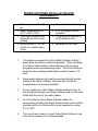
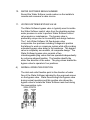
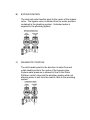
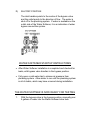
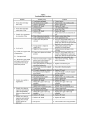
VALUE SERIES ELECTRONIC TIMER
WATER SOFTENER
Installation Manual
Barrie, Ontario Canada
L4N 4Y8
www.excaliburwater.com
EXCALIBUR VALUE WATER SOFTENER
INSTALLATION MANUAL
GENERAL WATER SOFTENER
INSTALLATION PROCEDURES
The Water Softener control valve, fittings and/or bypass Water
Softener valve are designed to accommodate minor plumbing
misalignments that may occur during the Water Softener installation.
Do Not use Vaseline, oils or other hydrocarbon lubricants when
installing your Value Water Softener or spray silicone anywhere. A
silicone lubricant may be used when installing your Value Water
Softener on black o-rings but is not necessary. Avoid any type of
lubricants including silicone when installing your Value Water
Softener on red or clear lip seals.
Do not use pipe dope or other sealants on the Water Softener
threads. Teflon tape must be used on the Water Softener threads
such as the 1 inch NPT elbow, the ¼ inch NPT connection, and the
Water Softener drain line connection. The nuts and caps of the Value
Water Softener are designed to be unscrewed or tightened by hand
or with the special plastic Water Softener service wrench part number
V3193. If necessary, pliers can be used to unscrew the Value Water
Softener nut or cap. No not use a pipe wrench to tighten or loosen
the Value Water Softener nuts or caps. Do not place screwdriver in
slots on caps and/or tap with a hammer as this could damage the
Value Water Softener
WATER SOFTENER INSTALLATION SITE
REQUIRMENTS
• Water pressure 20 – 125
psi
• Water temperature 5 to
30°C or 40 to 100°F
• The Water Softener tank
should be on a firm level
surface
• Electrical use of 115/120
volt 60 Hz uninterrupted
outlet
• Current draw is 0.25 amps
• A 15 foot power cord is
furnished
• The plug-in transformer is
for dry location only
• Batteries are not used
1.
The distance between the Value Water Softener and the
water drain should be as short as possible. When installing
your Value Water Softener all plumbing must be done in
accordance with local plumbing codes. The Water Softener
must not have a piping header that exceeds 3 meters (10
feet).
2.
Since water softener salt must be used periodically and be
added to the Water Softener, the brine tank should be
located where it is easily accessible.
3.
Do not install your Value Water Softener with less than 10
feet of piping between your Water Softener and it’s electrical
outlet and the inlet of the water heater.
4.
Do not locate the Value Water Softener where it’s
connections including the Water Softener drain and overflow
plumbing will be in a room with a room temperature under
2°C or 34°F.
5.
The use of resin cleaner in your Value Water Softener in an
unvented enclosure is not recommended.
6.
The Water Softener inlet/outlet plumbing will be installed
downstream of outdoor spigots. Install an inlet shutoff valve
and plumbing to the Water Softener bypass valve located at
the right rear as you face the Water Softener. There are a
variety of Water Softener installation fittings available. They
are listed under Water Softener installation fitting
assemblies. When assembling the Water Softener
installation fitting package (inlet and outlet) connect the
fitting to the plumbing system first and attach the Water
Softener nut, split ring and o-ring. Heat from soldering or
solvent cements may damage the Water Softener nut, split
ring or o-ring. Solder joints should be cool and solvent
cements should be set before installing the Water Softener
nut, split ring and o-ring. Avoid getting solder flux, primer
and solvent cement on any part of the Water Softener o
rings, split rings, bypass valve or control valve. If the
building electrical system is grounded to the plumbing
system, install a copper grounding strap from the inlet to the
outlet plumbing.
7. WATER SOFTENER DRAIN LINE
First, be sure that the Water Softener drain line can handle the
flow rate of the Water Softener. Solder joints near the drain line
must be done prior to connecting the Water Softener drain line
flow control fitting. Leave at least 6 inched between the Water
Softener drain line flow control fittings and solder joints. Failure to
do this could cause interior damage to the Water Softener flow
control. Install a ½ inch inside diameter flexible plastic tube to the
Water Softener drain line assembly or discard the tubing nut and
the 3/4 inch NPT fitting for rigid pipe. If the Water Softener
backwash flowrate is greater than 7 gallons per minute, use a ¾
inch Water Softener drain line. Where the Water Softener drain
line is elevated but empties into a water drain below the level of
the Water Softener control valve, form a 7 inch loop at the
discharge end of pipe so that the bottom of the loop is level with
the drain connection of the Water Softener control valve. This will
provide an adequate anti-siphon trap. Where the drain empties
into an overhead sewer pipe, a sink-type trap must be used. Run
a drain tube to its discharge point in accordance with local
plumbing codes. Pay special attention to plumbing codes for air
gaps and anti-siphon devices.
8. WATER SOFTENER BRINE TANK CONNECTION
Install a 3/8 inch outside diameter polyethylene tubing from the
Water Softener refill elbow to the brine valve in the Water Softener
brine tank.
9. WATER SOFTENER OVERLOW DRAIN TUBING
CONNECTION
A Water Softener overflow drain tubing is recommended where
a Water Softener brine tank overflow could damage furnishings
or the building structure. Your Value Water Softener will be
equipped with a brine tank safety float which greatly reduces
the chance of an accidental brine overflow. In the event of a
Water Softener malfunction, an overflow tubing connection will
direct the overflow to the drain instead of spilling on the floor
where it could cause considerable damage. This fitting should
be on the side of the Water Softener cabinet of brine tank. To
connect the Water Softener overflow fitting, locate a hole inside
of the brine tank. Insert the Water Softener overflow fitting into
the brine tank and tighten with plastic nut and gasket from the
inside. Attach a length of ½ inch inside diameter tubing (not
supplied) to fitting and run tubing to drain. Do not elevate the
Water Softener overflow tube higher than 3 inches below
bottom of overflow fitting. Do not “tie” this overflow tube into the
drain tube of the Water Softener control valve. Overflow tube
must be a direct, separate line from fitting to drain.
IMPORTANT:
Never insert a drain line directly into a drain, sewer line or
ptrap. Always allow an air gap between the drain line of the
waste water to prevent the possibility of sewage being backsiphoned in the Water Softener.
10.
WATER SOFTENER SERIAL NUMBER
Record the Water Softener serial number on the installer’s
records and consumer’s sales invoice.
11.
WATER SOFTENER BYPASS VALVE
The Water Softener bypass valve is typically used to isolate
the Water Softener control valve from the plumbing system,
water pressure in order to perform Water Softener control
valve repairs or maintenance. The bypass valve is
particularly unique due to its versatility and design features.
The 1 inch Water Softener full flow bypass valve
incorporates four positions including a diagnostic position
that allows to work on a pressure system while still providing
untreated bypass valve water to the residence. The bypass
valve is completely non-metallic, all composite design. The
Water Softener bypass valve consists of two
interchangeable plug valves that are operated independently
by red arrow shaped handles. The handles identify the
water flow direction of the water. The plug valves enable the
bypass valve to operate in four positions.
A)
NORMAL OPERATION POSITION
The inlet and outlet handles point in the direction of water
flow of the Water Softener indicated by the engraved arrows
on the bypass valve. Water flows through the bypass valve
during normal operation and this position also allows the
bypass valve to isolate the Water Softener resin bed during
the regeneration cycle.
B)
BYPASS POSITION
The inlet and outlet handles point to the centre of the bypass
valve. The bypass valve is isolated from the water pressure
contained in the plumbing system. Untreated water is
supplied to the plumbing system
C)
DIAGNOSTIC POSITION
The inlet handle points in the direction of water flow and
outlet handle points to the centre of the bypass valve.
System water pressure is allowed to flow to the Water
Softener control valve and the plumbing system while not
allowing water to exit from the control valve to the plumbing
system.
D)
SHUTOFF POSITION
The inlet handles points to the centre of the bypass valve
and the outlet points to the direction of flow. The water is
shut off to the plumbing system. If water is available on the
outlet side of the Water Softener, it is an indication of water
bypass around the system.
WATER SOFTENER STARTUP INSTRUCTIONS
• After Water Softener installation is completed and checked for
leaks, with bypass valve handles to the bypass position.
• Fully open a cold water tap to release air pressure from
plumbing system. Allow water to run until the plumbing system
is rid of debris, which may have occurred during installation.
THE WATER SOFTNER IS NOW READY FOR TESTING
1.
With the bypass valve in the bypass position, manually pour
5 gallons of water into the Water Softener brine tank.
2.
Press and hold the Water Softener UP & DN buttons
together for three seconds until the motor drive starts. Wait
until the motor stops in the backwash position displaying C1.
3.
Open the inlet handle of the bypass valve very slowly
allowing water to fill the Water Softener slowly to expel air
out the drain line. If water flows too rapidly, there will be a
loss of media out of the drain.
4.
When the Water Softener is flowing steadily to drain without
the presence of air, press the DN button to advance the
Water Softener control valve to the brine draw position, C2.
5.
Fully open the inlet of the Water Softener bypass valve
(bypass is no in the diagnostic position). Check to verify that
water is being drawn from the brine tank. There should be a
slow flow to the drain. Allow three minutes for the media bed
to settle.
6.
Press the Water Softener DN button to advance the Water
Softener control valve to where the display C3 which is a
second backwash with water running steadily to drain.
7.
Press the Water Softener DN button to advance to C4 which
is the fast rinse cycle that will settle the resin bed back to the
service position after backwashing.
8.
Press the Water Softener DN button to advance to C5 which
is the refill stage where you should have water refilling back
into the salt storage brine tank.
8.
Press the Water Softener DN button to advance to C5 the
control valve back will go through a quick wash.
9.
Press the Water Softener DN button to advance to C0 which
will send the control valve back into the service position
properly displaying the current time of day.
WATER SOFTENER PROGRAMMING SETTINGS
Step I:
Press up & dn buttons simultaneously for 3 seconds.
Step II:
Set time of regeneration which will already come factory
set for 2:00am. You want to pick a time when the least
amount of water is being consumed in the household.
Step III:
Press the dn button to set the days between regeneration.
This will come factory set for 4.
Step IV:
Press next dn button to display back to the current time of
day.
To initiate a manual regeneration immediately, press and hold the up
& dn buttons for three seconds. The system will begin to regenerate
immediately. The Water Softener control valve may be stepped
through the various regeneration cycles pressing the regen dn.
7 YEAR WARRANTY
Lifetime Tank Warranty
Value Water Softener
Thank you for your purchase of our VALUE SERIES WATER SOFTENER. For proof of purchase, please retain your
Invoice/Sales Order Copy.
Warranty ~ Offered
Excalibur Water Systems warranties its products to be free from defect in materials and workmanship to the original
owner from the date on the proof of purchase as described below.
Warranty ~ Working Procedures
If during the suitable warranty period, a part is defective, then Excalibur Water Systems will repair or replace that part at
no charge to the original owner, with the exception of charges for nominal shipping, service and/or installation.
Warranty ~ Coverage Outlined
Excalibur Water Systems guarantees, to the original owner, a period of 7 years, the CONTROL BODY to be free of
defects in materials and workmanship and to perform its proper functions. To the original owner, a period of 7 years,
the ELECTRONIC CONTROL VALVE as well as all parts to be free of defects in materials and workmanship and to
perform their normal functions. To the original owner, the SALT TANK and the MINERAL TANK will not rust, corrode,
leak, burst or in any other form fail to perform their proper functions for a LIFETIME period of 20 YEARS.
Warranty ~ Service
In the event you require service, your local Excalibur Water Systems Dealer will provide all necessary service and
installation for your Value Water Softener. To obtain warranty service within 30 days of discovery of the defect,
notification must be given to your local Excalibur Water Systems Dealer.
General Provisions
The above warranties are effective provided the VALUE WATER SOFTENER is operated at water pressures not
exceeding 125psi and at water temperatures not exceeding 120°F; also provided that the water softener is not subject
to abuse, misuse, alteration, neglect, freezing, accident or negligence; and provided further that the water softener is
not damaged as the result of any unusual force of nature such as, but not limited to flood, hurricane, tornado or
earthquake. Excalibur Water Systems is excused if failure to perform its warranty obligations is the result of strikes,
government regulation, materials shortages or other circumstances beyond its control.
THERE ARE NO WARRANTIES ON THE WATER SOFTENER BEYOND THOSE SPECIFICALLY DESCRIBED
ABOVE. ALL IMPLIED WARRANTIES, INCLUDING ANY IMPLIED WARRANTY OF MERCHANTABILITY OR OF
FITNESS FOR A PARTICULAR PURPOSE, ARE DISCLAIMED TO THE EXTENT THEY MIGHT EXTEND BEYOND
THE ABOVE PERIODS. THE SOLE OBLIGATION OF EXCALIBUR WATER SYSTEMS UNDER THESE
WARRANTIES IS TO REPLACE OR REPAIR THE COMPONENT OR PART PROVES TO BE DFEFECTIVE WITHIN
THE SPECIFIED TIME PERIOD AND EXCALIBUR WATER SYSTEMS IS NOT LIABLE FOR CONSEQUENTIAL OR
INDIDENTAL DAMAGES. NO DEALER, AGENT, REPRESENTATIVE OR OTHER PERSON IS AUTHORIZED TO
EXTEND OR EXPAND THE WARRANTIES EXPRESSED ABOVE.
Certain provinces or states do not allow limitations on how long an implied warranty lasts or exclusions or limitations of
incidental or consequential damage, therefore limitations and exclusions in this warranty may not apply to you. This
warranty extends you specific legal rights as you may have other rights which vary from province to province or state to
state.
Excalibur Water Systems is a manufacturer of water treatment products.
Barrie, ON
Canada