1
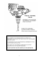
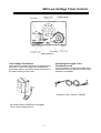
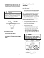
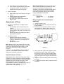
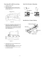
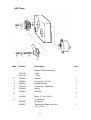
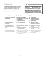
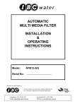
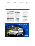
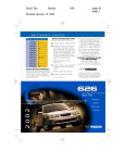
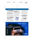
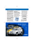
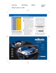
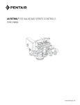
AUTOMATIC
NEUTRALISING
FILTER
INSTALLATION
&
OPERATING
INSTRUCTIONS
Model:
AFN09-263
Serial No:
…………………………
Manufacturer and Supplier of
FILTRATION & WATER TREATMENT PRODUCTS
for commercial, industrial and residential application
Telephone: (07) 3219 2233
Email: [email protected]
Facsimile: (07) 3219 2266
Website: www.ibcwater.com.au
-1-
TYPICAL CONTROL
VALVE
ASSEMBLE TOP STRAINER
TO CONTROL VALVE BODY
(Push in and twist)
RISER PIPE ASSEMBLY
(Located centrally in strainer)
(When valve is screwed into tank)
NOTE:
ON A NUMBER OF SOFTENER MODELS & FILTERS IT IS
NECESSARY TO PACKAGE THE VALVE WITH THE TOP STRAINER
SUPPLIED LOOSE.
IT IS IMPORTANT THAT THIS STRAINER AS ASSEMBLED TO THE
VALVE DURING INSTALLATION.
THE LENGTH OF THE INTERNAL RISER PIPE IS FACTORY
ADJUSTED FOR THE TANK SIZE PROVIDED.
DO NOT SHORTEN THIS PIPE UNDER ANY CIRCUMSTANCES
-2-
WARNING
For proper operation, the inlet water pressure must be between 140 kPa and 690 kPa. If
the inlet pressure exceeds 690 kPa, a pressure reduction valve must be fitted prior to the
filter.
If water hammer is prevalent, a water hammer arrestor must also be fitted after the filter.
Ie. Between the filter and the device causing the effect.
Failure to observe the above will VOID warranty.
An Integral Backflow Prevention device must be fitted to the influent supply.
The Installation must comply with all relevant local and State/Australian Standards
Plumbing Codes.
CAUTION:
DO NOT USE WHERE WATER IS MICROBILOGICALLY UNSAFE OR
WITH WATER OF UNKNOWN QUALITY
INSTALLATION
1. Position the filter on a flat surface close to a drain or a properly trapped outlet and in a
position where the filter can service all the lines, which require filtered water. The filter
should be placed far enough away from a water heater to avoid any hot water backup
into the filter. The AF model filters require a standard or weatherproof 3-pin 10-amp
power point, depending on the location of filter installation.
2. Refer page 8 of “Series 263 Installation, Operation & Maintenance Manual” for
plumbing instructions.
3. Remove filter valve from carton. Attach top strainer to bottom of valve. Plug or cover
the top end of riser pipe in the tank making sure no media can enter the tube.
4. Fill tank to about 1/3 full with water, making sure the riser pipe is sitting in the middle of
the tank. Then using a wide mouth funnel place the media in the tank as follows –
levelling each layer before placing next media into the tank. DO NOT shake filter to
level the media.
5. Remove the plug or cover from the riser pipe making sure you DO NOT lift the riser
pipe. Top up tank with water. Screw valve onto the tank (hand tight is usually
sufficient), making sure the distributor tube is properly inserted into the top strainer
-3-
MEDIA PLACEMENT
NEUTRALISING FILTER
Sequence in Tank
AFN09
1st
5kg #6 Gravel
2nd
30kg Neutralite
The neutralising filter is utilised to raise the pH of the water.
The raw water should not contain any suspended solids or matter.
The filter should be given an initial backwash only and should only require backwashing
once a week.
The media will dissolve over a period of time and will have to be replenished on a regular
basis. It is advisable to check the pH of the treated water on a weekly basis and the media
will have to be replenished when the test shows that the pH is not being increased
-4-
440i Low Voltage Timer Control
Low Voltage Transformer
Only use the included transformer for powering the
440i timer. Connect the plug of the transformer
secondary cable to the mating socket at the rear of
the timer housing on the motor
Increasing the length of the
Transformer cord
If it is necessary to extend the length of the
transformer cord, an optional 15 foot (4.6m)
extension is available
Extension Cord - Part No. 1000907
Be certain that the transformer is plugged
into a correct voltage source
-5-
Series 263
3-Cycle Control System for Automatic Filters
Installation, Operation and Maintenance Manual
-6-
TABLE OF CONTENTS
Installation ……………………………………………….
8
Location Selection
Water Line Connection
Drain Line Connection
Electrical Connection
Placing Conditioner into Operation ………………….
9
Adjustment of timer ……………………………………..
10
Special Features of Timer
Removing Control Module for Servicing ……………
10
Removing 440I for Servicing …………………………..
11
Valve Disc Operation ……………………………………
11
Valve Disc Identification ………………………………
11
Specifications ……………………………………………
12
Flow Diagrams ………………………………………….
13
Pressure Loss Characteristics ………………………
13
Replacement Parts ……………………………………..
14, 15, 16
Trouble Shooting ………………………………………..
17
-7-
Installation
All plumbing and electrical connections must
conform to local codes.
Inspect unit carefully for carrier shortage or
shipping damage.
Location Selection
1. The distance between the unit and a drain
should be as short as possible.
2. It is likely that supplementary water treating
equipment will be required, make certain
adequate space is available
Figure 1
3. Do not install unit closer to a water heater than
a total run of 10 feet (3m) of piping between the
outlet of the conditioner and the inlet to the
heater. Water heaters can sometimes overheat
to the extent they will transmit heat back down
the cold pipe into the unit control valve.
Hot water can severely damage the
conditioner. A 10 foot (3m) total pipe, including
bends, elbows, etc., is a reasonable to help
prevent this possibility. A positive way to
prevent hot water from flowing from heat
source to the conditioner, in the event of a
negative pressure situation, is to install a check
valve in the water piping from the conditioner. If
a check valve is installed, make certain the
water heating unit is equipped with a
properly rated temperature and pressure
safety relief valve. Also, be certain that local
codes are not violated
4. DO not locate unit where it or its connections
(including the drain and overflow lines) will ever
be subjected to room temperatures under 34ºF
(1ºC) or over 120ºF (49ºC).
5. Do not install unit near acid or acid fumes.
Water Line Connections
A bypass valve system must be installed since
there may be occasions when the water conditioner
must be bypassed for unfiltered water or for
servicing.
The most common bypass systems are the Autotrol
Bypass Valve (Figure 1) and plumbed-in globe
valves (Figure 2). Though both are similar in
function, the Autotrol Bypass offers simplicity and
ease of operation.
-8-
Figure 2
Drain Line Connection
1. If ideally located, the unit will be above and not
more than 20 feet (6.1m) from the drain. For
such installations connect 1/2-inch (1.3cm)
plastic tubing to drain line connection located
on the control.
2. If he unit is located more than 20 feet (6.1m)
from drain, use 3/4-inch (1.9cm) tubing for runs
up to 40 feet (12.2m). Also purchase adapter to
bush tubing down to drain line connection
fitting.
3. If unit is located where the drain line must be
elevated, you may elevate the line up to 6 feet
(1.8m) providing the run does not exceed 15
feet (4.6m) and water pressure at conditioner is
not less than 40 psi (2.8 BAR). You may
elevate an additional 10 psi (0.7 BAR).
4. Where drain line is elevated but empties into a
drain below the level of the control valve, from
a 7-inch (18cm) loop at the far end of the line
so that the bottom of the loop is level with the
drain line connection. This will provide an
adequate trap.
Placing Conditioner into
Operation
After all previous steps have been completed, the
unit is ready to be placed into operation. Follow
these steps carefully.
1. Remove control valve cover by springing back
the rear plastic tab at the end of the camshaft.
Lift the back of the cover and slide forward.
Caution
Never connect drain line into a drain, sewer
line or trap. Always allow an air gap between
the drain line and the wastewater to prevent
the possibility of sewage being backsiphoned into conditioner.
Note: The following steps will require you turning
the pointer knob, (Figure 4), to various positions.
Insert a wide blade screwdriver into arrow slot in
pointer knob and press firmly. With the knob held
in, rotate COUNTERCLOCKWISE only until arrow
or knob points to desired position. (Rotation is
made much easier if you grasp the camshaft with
your free hand and turn it at the same time). Then
permit the knob to spring back out.
2. Insert screwdriver into slot in pointer knob,
(Figure 4). Press in and rotate knob
COUNTERCLOCKWISE until arrow points
directly to the word BACKWASH.
3. Fill mineral tank with water.
A. With water supply off, place the bypass
valve(s) into the "not in bypass" position.
B. Open water supply valve very slowly to
approximately the 1/4 open position.
C. When all of the air has been purged from
the tank (water begins to flow steadily from
the drain), open the main supply valve all
the way.
Figure 3
Electrical Connection
-
240Volt 10amp Mains Supply.
-
Transformer supplied to reduce to 12V.
-
Plug lead end into socket on back of TIMER
Motor.
Caution
If opened too rapidly or too far, media may
be lost. In this position, you should hear air
escaping slowly from the drain line.
Figure 4
-9-
D. Allow water to run to drain until clear.
E. Turn off water supply and let the unit stand
for about 5 minutes. This will allow all
trapped air to escape from the tank.
4. Put into operation.
A. Open water supply valve slowly to full open
position.
B. Advance pointer knob COUNTERCLOCKWISE to SERVICE.
C. Run water from nearby faucet until the
water is clear.
Adjustment of Timer
1. Set days of regeneration on skipper wheel
(Figure 4).
• Pull all skipper pins outward (away from
control).
• Rotate skipper wheel until day arrow points
to current day (7-day timer) or number 1 (6day timer).
• Depress skipper pin(s) at day(s) for which
regeneration is desired.
Manual Regeneration. Electricity is used only to
run the timer and rotate the camshaft. All other
functions are operated by water pressure.
Therefore, in the event of a power outage, all the
various regeneration positions may be dialled
manually by depressing the pointer knob and
turning COUNTERCLOCKWISE.
Manual time cycle:
BACKWASH ………….. 20 minutes
RINES …………………. 10 minutes
Removing the valve assembly for
servicing
1. Unplug the power cord.
2. Shut off water supply or put bypass valve into
bypass position.
3. Remove cover and with screwdriver, relieve
tank pressure by pushing open valve No. 7
(rear flapper on control as shown (Figure 8).
2. Set the time of day
• Grasp timer knob and pull outward.
• Rotate in either direction until actual time of -day on time dial is in line with time-ofday arrow.
• Release timer knob.
Note: With the time of day properly set, the conditioner will regenerate at about 2:30a.m. If you prefer
to have the unit regenerate at an earlier or later
time, simply set the time-of-day accordingly.
Example:
To have the unit REGENERATE/BACKWASH at
4:30 a.m. - 2 hours later - set the clock 2 hours
earlier than the actual current time
Special features of timer
Guest Cycle. When abnormally high water usage
exhausts your water conditioner's capacity ahead of
schedule, an extra regeneration can be achieved by
depressing the pointer knob with finger or wide
blade screwdriver and turning COUNTERCLOCKWISE to START. It will take few minutes for
regeneration to start. Normal regeneration
schedule will not be disrupted.
- 10 -
Figure 8
4. When used with a globe valve bypass, loosen
and detach the inlet, outlet, brine and drain
lines from the valve. If using the 1264 bypass,
loosen and remove valve from bypass as well
as loosening and removing the brine and drain
lines.
5. Unscrew (counterclockwise) and remove valve
from tank.
6. To replace the control valve, reverse the above
procedure.
Removing 440i or 460i for servicing
Valve Disc Principle of Operation
1. Unplug the power cord.
2. Remove the cover.
3. Align the indicator arrow on the rear of the
camshaft with the top of the rear hoop of the
top plate (Figure 16).
Identification of Control Valving
Figure 16
4. Remove the camshaft by carefully pushing the
securing tab, located at the rear of the
camshaft, away from the camshaft until the tab
disengages from the camshaft. Push the back
of the camshaft down and out to the inlet side
of the valve (Figure 17).
Figure 17
5. Disengage the front of the camshaft from the
output gear of the control.
6. Remove the timer locking pin and lift the control
straight up and off the valve.
7. To reinstall the camshaft and control, reverse
the above procedures.
- 11 -
Specifications
Hydrostatic Test Pressure ……………………………………………………………………. 300 psi (20.69 bar)
Working Pressure …………………………………………………………………… 20-125 psi (1.38 - 8.62 bar)
Standard Electrical Rating ……………………………………………………………………………. 115V 60 Hz
Optional Electrical Rating …………………… 115V 50 Hz, 230V 50Hz, 200V 60 Hz, 24V 60Hz, 24V 50 Hz,
100V 60 Hz, 12V 50Hz/transformer, 12V 60 Hz/transformer
Electrical Cord (standard rating) ………………………………………………. 60 inch (1.5m) 3-wire with plug
Pressure Tank Thread ………………………………………………………………………….. 2 1/2 inch-8 male
Riser Pipe Diameter Required ……………………………………………………….. 1.050 inch OD (26.7 mm)
Riser Pipe Length …………………………1/1/8 ± 1/8 inches (31.8 mm) higher than the top of mineral tank
Standard Connection …………………………………………………. 1-inch (25.4 mm) copper tube adapters
Optional Connections …………………………………… 31/-inch, 22 mm, and 28 mm copper tube adapters
3/4-inch BSPT, 1-inch BSPT, 1-inch NPT brass pipe adapters
3/4-inch, 1-inch, 25 mm CPVC tube adapters
Drain Line Connection ………………………………………………………………………… 3/4-inch NPT male
Optional Bypass Valve …………………………………. Rotating handle, full 1-inch porting, reinforced Noryl
Control Module, Tank Adapter …………………………………………………………………. Reinforced Noryl
Rubber Goods ………………………………………………………………… Compound for cold water service
Program Clock (Timer) …………………………………………………… 440i: Available in 6 or 7 day English
- 12 -
Flow Diagrams
1. Service Position
2. Backwash Position
3. Purge Position
Pressure Loss Characteristics
- 13 -
Replacement Parts
1265 Bypass
- 14 -
Parts List
code
Part No
Description
1
2
3
4
5
6
1035606
1035624
1301391
1000219
1010428
1032978
Valve Assembly
Camshaft 440I
Timer Locking Pin
Drain Cap
Riser O'ring Seal
Injector Assembly:
- Injector
Injector Cap Assembly:
- Cap
Top Strainer
Refill Control Plug
Screen/Cap Assembly
O'ring
Tank Ring
Plumbing Adapter Kits:
1-inch BSPT Plastic Pipe Adapter Kit
External Backwash Flow Control
AFM09
AFM12
Spring, Flapper Valve
Valve Disc Kit:
Standard
Severe Service
I-lid Cover
7
1000219
8
9
10
11
12
13
D1230
1030334
1000226
1010429
1035622
1001605
14
15
*
MA02320FCFF
MA04120FCFF
1001580
1041174
1041175
*
1000062
* Not Shown
- 15 -
Qty
1
1
1
1
1
1
1
1
1
1
1
1
1
1
1
1
1
440i Timer
code
Part No
Description
1031740
1301742
1030659
1006091
1006601
1031756
1030830
1030821
Skipper Wheel Assembly:
6-Day
7-Day
Washer
Screw, No 6 x 1/2 in
Bowed Washer
Tripper Arm Assembly
Spring
Retainer
1
2
3
4
5
6
7
8
*
9
*
1001568
1000812
1000907
Motor, 12 Volt, 50 Hz
Transformer:
Australian
Transformer Extension Cord
15 ft. (4.6m)
- 16 -
Qty
1
1
7
1
1
1
1
1
1
1
Caution
Troubleshooting
The technology upon which the series 263 control
is based, is well established and proven in service
over many years. However, should a problem or
question arise regarding the operation of the
system, the control can be very easily serviced. For
parts mentioned refer to exploded views in the
Replacement Parts section of this manual.
Problem
Service procedures that require the water
pressure to be removed from the system are
marked with a
after the possible cause.
To remove water pressure from the system,
put the bypass valve or three-valve bypass
into the bypass position and open the
Backwash Drain Valve (the sixth valve back
from the control) with a screwdriver. Restore
system water pressure when the service work
is completed.
Possible Cause
Solution
1. Control will not regenerate
automatically.
a. Electric cord unplugged.
b. Skipper pins not down on time
skipper wheel.
c. Defective timer motor.
a. Connect power.
b. Depress pins for day's
regeneration required.
c. Replace motor.
2. Control regenerates at
wrong time.
a. Timer set incorrectly.
a. Make correct setting
according to instructions.
3. Control backwashes at
excessively low or high
rate.
a. Incorrect backwash controller
used.
b. Foreign matter affecting
controller operation.
a. Replace with correct size
controller.
b. Remove and clean
controller.
4. Flowing or dripping water
at drain after regeneration.
a. Drain valve (5 or 6) held open
by foreign matter or particle.
b. Valve stem return spring on
top plate weak.
a. Manually operate valve stem
to flush away obstruction.
b. Replace spring.
- 17 -