1
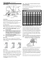
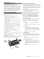
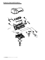
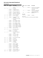
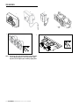
Autotrol® 255 Valve/400 Series Controls
SERVICE manual
www.pentairaqua.com
TABLE OF CONTENTS
• The drain line must be a minimum of 1/2" diameter. Use
3/4" pipe if the backwash flow rate is greater than 5 GPM
(18.9 Lpm) or the pipe length is greater than 20 feet (6
m).
• Do not support the weight of the system on the control
valve fittings, plumbing, or the bypass.
General
• Keep the media tank in the upright position. Do not turn
on side, upside down, or drop. Turning the tank upside
down will cause media to enter the valve.
• Operating ambient temperature is between 34ºF (1ºC)
and 120ºF (49ºC).
• Operating water temperature is between 34ºF (1ºF) and
100ºF (38ºC).
• Working water pressure range is 20 to 125 psi (1.38
to 8.61 bar). In Canada the acceptable working water
pressure range is 20 to 100 psi (1.38 to 6.89 bar).
• Use only regenerant salts designed for water softening.
Do not use ice melting, block, or rock salts.
• Follow state and local codes for water testing. Do not use
water that is micro-biologically unsafe or of unknown
quality.
• When filling media tank, do not open water valve
completely. Fill tank slowly to prevent media from exiting
the tank.
• When installing the water connection (bypass or
manifold) connect to the plumbing system first. Allow
heated parts to cool and cemented parts to set before
installing any plastic parts. Do not get primer or solvent
on O-rings, nuts, or the valve.
MANUAL OVERVIEW
How To Use This Manual
SAFETY INFORMATION
California Proposition 65 Warning
WARNING: This product contains chemicals known to the
Electrical
2 • Autotrol 255 Valve/400 Series Service Manual
®
AND CERT
I
DS
TES
T
ED
D
FIE
• Do not use petroleum based lubricants such as
petroleum jelly, oils, or hydrocarbon based lubricants.
Use only 100% silicone lubricants.
• All plastic connections should be hand tightened.
Plumber's tape may be used on connections that do not
use an O-ring seal. Do not use pliers or pipe wrenches.
• All plumbing must be completed according to local
codes.
• Soldering near the drain line should be done before
connecting the drain line to the valve. Excessive heat will
cause interior damage to the valve.
• Do not use lead-based solder for sweat solder
connections.
SYSTEM SPECIFICATIONS
ER
Mechanical
State of California to cause cancer or birth
defects or other reproductive harm.
U ND
There are no user-serviceable parts in the AC adapter,
motor, or controller. In the event of a failure, these should be
replaced:
• All electrical connections must be completed according
to local codes.
• Use only the power AC adapter that is supplied.
• The power outlet must be grounded.
• To disconnect power, unplug the AC adapter from its
power source.
IN
AR
This installation manual is designed to guide the installer
through the process of installing and starting conditioners
featuring the 400 series controllers.
This manual is a reference and will not include every system
installation situation. The person installing this equipment
should have:
• Training in the 400 series controllers and water
conditioner installation
• Knowledge of water conditioning and how to determine
proper control settings
• Basic plumbing skills
• The directional instructions "left" and “right" are
determined by looking at the front of the unit.
DU
D
MANUAL OVERVIEW.............................................................2
SAFETY INFORMATION.........................................................2
SYSTEM SPECIFICATIONS....................................................2
EQUIPMENT INSTALLATION.................................................4
SYSTEM STARTUP.................................................................6
PROGRAMMING....................................................................6
SERVICE AND Maintenance.............................................9
255 Valve & Tank Adapter module ........................... 10
255 Series......................................................................... 12
Troubleshooting.......................................................... 14
FLOW DIAGRAMS................................................................ 16
FLOW DATA CHARTS........................................................... 17
A
STR Y ST
N
The systems below have been tested and certified
by the WQA to NSF/ANSI Std. 44 and NSF/ANSI 372
for “lead free” compliance.
The 255 valve has been tested and certified by the WQA to
NSF/ANSI Std. 61 Section 8 Mechanical Devices
WQA Certified 255-460i Systems:
255-460i-075-844
255-460i-100-948
Working Pressure:
20-125 psi (1.38 - 8.61 bar)
Standard 12 Volt Transformer
Input Electrical Rating:
115V 60 Hz
Optional 12 Volt Transformer
Input Electrical Rating:
Operating Ambient
Temperature:
115V 50 Hz, 230V 50 Hz,
230V 60 Hz, 100V 60 Hz,
100V 50 Hz
34-120°F (1-49°C)
Operating Water Temperature:
34-100°F (1-38°C)
For service or parts, please contact your local professional
water treatment dealer.
1.7
0.75
1.7
1.7
Maximum Flow Rate During
Regeneration (gpm)
Sybron C-249NS
Ion Exchange Resin (cu. ft)
Backwash - GPM
Fast Rinse/Purge - GPM
2.1
2.1
1.0
2.1
Autotrol 255 Valve/400 Series Service Manual • 3
®
Pentair Residential Filtration, LLC
Date: _________________________
Buyer: ______________________________________________________________
PENTAIR Residential Filtration, LLC
5730 North Glen Park Road Milwaukee, Wisconsin 53209
PHONE: (262)-238-4400
Date: _________________________
Seller: ______________________________________________________________
These water softener systems have been tested by WQA and conform to NSF/ANSI 44 for specific performance claims as verified and substantiated by test data. The rated salt efficiencies above
were also determined in accordance with NSF/ANSI 44 and are only valid at the salt dosage referenced above. An efficiency rated water softener is a demand initiated regeneration (DIR) softener
which also complies with specific performance specifications intended to minimize the amount of regenerant brine and water used in its operation. Efficiency rated water softeners shall have a rated
salt efficiency of not less that 3350 grains of total hardness exchanged per pound of salt (based on NaCl equivalency) (477 grams of total hardness exchanged per kilogram of salt), and shall not
deliver more salt than its listed rating. The rated efficiency of the water softener, the salt dosage at that efficiency, the capacity at that salt dosage and that of the efficiency is only valid at the stated salt
dosage. Efficiency is measured by a laboratory test described in NSF/ANSI 44. The test represents the maximum possible efficiency the system can achieve. Operational efficiency is the actual
efficiency achieved after the system has been installed. It is typically less than the efficiency due to individual application factors including water hardness, water usage, and other contaminants that
reduce the water softener’s capacity. These systems are not intended to be used for treating water that is microbiologically unsafe or of unknown quality without adequate disinfection before or after
the system. Refer to the system Installation and Service Manuals for set-up and programming instructions.
Contact your local Autotrol dealer for parts and service. See your owner’s manual for warranty information.
Important Notice: For conditions of use, health claims certified by the California Department of Public Health and replacement parts, see product data sheet
Iowa Requirement:
Operating Pressure:20 -125 psi or 1.4 – 8.8 kg/Centimeter2, Operating Temperature: 34 - 100° F or 1.1 – 38° C
Acceptable Salt Type: Sodium Chloride – Pellet or solar salt for water softeners
All Systems above tested at 35psi +/- 5 psi, pH of 7.5 +/- 0.5, Capacity Testing Flow Rate = 50% of the rated service flow rate for the various size systems.
4,096/lb. salt @ 3.75
Rated Efficiency
(grains/lb Salt @ lb. of salt)
4,096/lb. salt @ 5.0
20,483 @ 5.0
28,263 @ 10.0
30,865 @ 14.0
15, 362 @ 3.75
21,197 @ 7.5
23,148 @ 10.5
Rated Capacity
(grains @ lb. of salt)
15.0
9.0
Pressure Drop at Rated
Service Flow Rate (psi)
10.0
255-460i-100-948
6.0
255-460i-075-844
Rated Service Flow (gpm)
Model
WATER SOFTENER PERFORMANCE DATA SHEET
The valve used on this unit is
Tested and Certified by WQA
to NSF/ANSI Std. 61 Section
8 for Material Safety Only
Tested and Certified by
WQA against NSF/ANSI
Standard 44 & NSF/ANSI
372
for
“lead
free”
compliance.
SYSTEM SPECIFICATIONS continued
EQUIPMENT INSTALLATION
Autotrol 255 Valve Control Module Features
400 Series Control
4. Fast Rinse (Downflow):
The control directs water down through the resin bed and
up through the riser tube to the drain. Any remaining brine
residual is rinsed from the resin bed.
5. Brine Refill (Downflow):
Optional i-lid Cover
Brine refill occurs during a portion of the fast rinse cycle.
Water is directed to the regenerant tank at a controlled rate, to
create brine for the next regeneration.
6. Repressurize Cycle — (No Flapper Open):
Variable Brine
Control
This cycle closes all flappers for a short time to allow the
air and water to hydraulically balance in the valve before
continuing the regeneration.
Air Check
To Regenerant
Tank
From Regenerant
Tank
Injector Access Plug
Figure 1
Tank Adapter Module Features
Optional Bypass
B Y PA S S
Brine Line Fitting
Connection 1/4-inch NPT
B Y PA S S
Air Check
Probe Connection Slot
Inlet Connection
3/4-inch or 1-inch
NPT or BSPT
Tank Thread 2-1/2 inch - 8 male
Drain Connection
3/8-inch or
1/2-inch NPT or
BSPT
Outlet connection
3/4-inch or 1-inch
NPT or BSPT
Figure 2
System Regeneration Cycles
1. Service (Downflow):
Untreated water is directed down through the resin bed and up
through the riser tube. The hardness ions attach themselves
to the resin and are removed from the water. The water is
conditioned as it passes through the resin bed.
2. Backwash (Upflow):
The flow of water is reversed by the control valve and directed
down the riser tube and up through the resin bed. During the
backwash cycle, the bed is expanded and debris is flushed to
the drain.
3. Brine/Slow Rinse (Downflow):
The control directs water through the brine injector and brine
is drawn from the regenerant tank. The brine is then directed
down through the resin bed and up through the riser tube to
the drain. The hardness ions are displaced by sodium ions and
are sent to the drain. The resin is regenerated during the brine
cycle. Brine draw is completed when the air check closes.
4 • Autotrol 255 Valve/400 Series Service Manual
®
SERVICE
BACKWASH
C0
C1 and C6
BRINE/SLOW RINSE
C2 and C3
REPRESSURIZE
C4
FAST RINSE
C5 and C7
BRINE REFILL
C8
Figure 3
NOTE: All plumbing must conform to local codes. Inspect
unit carefully for carrier shortage or shipping damage.
Location Selection
1. The distance between the unit and a drain should be as
short as possible.
2. If it is likely that supplementary water treating equipment
will be required, make certain adequate additional space
is available.
3. Since salt must be added periodically to the brine tank, the
location should be easily accessible.
4. Do not install any unit closer to a water heater than a total
run of 10 feet (3 m) of piping between the outlet of the
conditioner and the inlet to the heater. Water heaters can
sometimes overheat to the extent they will transmit heat
back down the cold pipe into the unit control valve. Hot
water can severely damage the conditioner. A 10 foot (3-m)
total pipe run, including bends, elbows, etc., is a reasonable
distance to help prevent this possibility. A positive way to
prevent hot water from flowing from heat source to the
conditioner, in the event of a negative pressure situation,
is to install a check valve in the soft water piping from
the conditioner. If a check valve is installed, make certain
the water heating unit is equipped with a properly rated
temperature and pressure safety relief valve. Also, be
certain that local codes are not violated.
5. Do not locate unit where it or it’s connections (including
the drain and overflow lines) will ever be subjected to room
temperatures under 34°F (1°C) or over 120°F (49°C).
6. Do not install unit near acid or acid fumes.
7. The use of resin cleaners in an unvented enclosure is
not recommended.
EQUIPMENT INSTALLATION continued
Water Line Connection
The installation of a bypass valve system is recommended to
provide for occasions when the water conditioner must be
bypassed for hard water or for servicing.
The most common bypass systems are the Autotrol® Series
256 bypass valve (Figure 4) and plumbed-in globe valves
(Figure 5). Though both are similar in function, the 256
Autotrol bypass offers simplicity and ease of operation.
Not in Bypass
In Bypass
Drain
Figure 6
NOTE: Standard commercial practices have been expressed
here. Local codes may require changes to
these suggestions.
BY
PA S S
BY
PA S S
BY
BY
PA S S
PA S S
Brine Line Connection
Figure 4 Autotrol Series 256 Bypass Valve
Not in Bypass
Correct
Right WayWay
Drain Line Tube
In Bypass
It will be necessary to install the brine tube and line to a fitting
installed on the air check. Apply plumber tape on all
threaded connections.
Be sure all fittings and connections are tight so that premature
checking does not take place. Premature checking is when
the ball in the air check falls to the bottom before all brine
is drawn out of the brine tank. See Placing Conditioner into
Operation section.
Overflow Line Connection
Water
Conditioner
Water
Conditioner
Figure 5 Typical Globe Valve Bypass System
Drain Line Connection
1. Ideally located, the unit will be above and not more than
20 feet (6.1 m) from the drain. For such installations, use
an appropriate adapter fitting (not supplied), to connect
1/2 inch (1.3 cm) plastic tubing to the drain line connection
of the control valve.
In the absence of a safety overflow and in the event of
a malfunction, the BRINE TANK OVERFLOW will direct
“overflow” to the drain instead of spilling on the floor where it
could cause considerable damage. This fitting should be on the
side of the cabinet or brine tank.
To connect overflow, locate hole on side of brine tank. Insert
overflow fitting (not supplied) into tank and tighten with plastic
thumb nut and gasket as shown (Figure 7). Attach length of
1/2 inch (1.3 cm) I.D. tubing (not supplied) to fitting and run to
drain. Do not elevate overflow line higher than 3 inches
(7.6 cm) below bottom of overflow fitting. Do not tie into drain
line of control unit. Overflow line must be a direct, separate
line from overflow fitting to drain, sewer or tub. Allow an air
gap as per drain line instructions (Figure 6).
Brine Tank
Overflow Fitting
Installed
2. If the unit is located more than 20 feet (6.1 m) from drain,
use 3/4 inch (1.9 cm) tubing for runs up to 40 feet (12.2 m).
Also, purchase appropriate fitting to connect the 3/4 inch
tubing to the 1/2 inch NPT drain connection.
3. If the unit is located where the drain line must be elevated,
you may elevate the line up to 6 feet (1.8 m) providing the
run does not exceed 15 feet (4.6 m) and water pressure
at conditioner is not less than 40 psi (2.76 bar). You may
elevate an additional 2 feet (61 cm) for each additional
10 psi (0.69 bar).
4. Where the drain line is elevated but empties into a drain
below the level of the control valve, form a 7-inch (18 cm)
loop at the far end of the line so that the bottom of the loop
is level with the drain line connection. This will provide an
adequate siphon trap.
5. Where the drain empties into an overhead sewer line, a
sink-type trap must be used.
IMPORTANT: Never insert drain line into a drain, sewer line or
trap. Always allow an air gap between the drain line and the
wastewater to prevent the possibility of sewage being backsiphoned into conditioner.
Connect 1/2-inch
(1.3 cm) Tubing or
Hose and Run to
Drain
Figure 7
Low Voltage Transformer
Use only the included transformer for powering the 400 series
timers. Connect the plug of the transformer secondary cable
to the mating socket on the control (see Figure 8).
Be certain that the transformer is plugged into a correct
voltage source that is not controlled by a wall switch.
Autotrol 255 Valve/400 Series Service Manual • 5
®
EQUIPMENT INSTALLATION continued
Increasing the Length of the Transformer Cord
If it is necessary to extend the length of the transformer cord,
an optional 15 foot (4.6 m) extension is available
(see Figure 9).
Air Check
Brine Line
Figure 8
Figure 9 - Control Valve
5. Put into operation.
a. Open water supply valve slowly to full open position.
SYSTEM STARTUP
Initial Startup
After the water conditioning system is installed, the
conditioner should be disinfected before it is used to treat
potable water. Refer to the Disinfection of Water Conditioners
section in this manual. Complete the following steps to place
the conditioner into operation:
1. Remove control valve cover.
NOTE: The following steps will require turning the indicator
knob (Figure 11) to various positions. Insert a
wide-blade screwdriver into arrow slot in indicator
knob and press in firmly. With knob held in, rotate
COUNTERCLOCKWISE only until arrow or knob points
to desired position. Rotation is made much easier if
you grasp the camshaft with your free hand and turn it
at the same time. Then permit knob to spring back out.
2. Insert screwdriver into slot in indicator knob (Figure 11).
Press in and rotate knob COUNTERCLOCKWISE until arrow
points directly to the word BACKWASH.
3. Fill resin tank with water.
b. Carefully advance indicator knob
COUNTERCLOCKWISE to center of FAST RINSE/REFILL
position and hold there until air check (Figure 10) fills
with water and water starts to flow through brine line
into brine tank. Do not run for more than two minutes.
c. Advance indicator knob COUNTERCLOCKWISE until
arrow points to the center of the BRINE/SLOW
RINSE position.
d. With the conditioner in this position, check to see if
water is being drawn from the brine tank. The water
level in the brine tank will recede very slowly. Observe
for at least three minutes. If the water level does not
recede or goes up, or if air enters the transparent air
check chamber and the ball falls and seats, reference
Troubleshooting section.
e. Advance indicator knob COUNTERCLOCKWISE to
CONDITIONED WATER.
f. Run water from a nearby faucet until the water is clear
and soft.
PROGRAMMING
440i Control (obsolete)
Day Arrow
Skipper Pins
Skipper Wheel
a. With water supply off, place the bypass valve(s) into the
“NOT IN BYPASS” position.
b. Open water supply valve very slowly to approximately
the 1/4 open position.
IMPORTANT: If opened too rapidly or too far, resin may be lost.
In this position, you should hear air escaping slowly from the
drain line.
c. When all of the air has been purged from the tank
(water begins to flow steadily from the drain), open the
water supply valve all the way.
d. Allow water to run to drain until clear.
e. Turn off water supply and let the unit stand for about
five minutes. This will allow all trapped air to escape
from the tank.
4. Add water to brine tank (initial fill). With a bucket or hose,
add approximately 4 gallons (15 liters) of water to brine
tank. If the tank has a salt platform above the bottom of the
tank, add water until the level is approximately 1 inch
(25 mm) above the platform.
6 • Autotrol 255 Valve/400 Series Service Manual
®
Indicator Knob
Timer
Locking Pin
Time Arrow
Figure 10
Timer Knob
PROGRAMMING continued
Programming
1. Set days of regeneration on skipper wheel (Figure 11).
• Pull all skipper pins outward (away from control).
• Rotate skipper wheel until day arrow points to current
day or number 1.
• Depress skipper pin(s) at day(s) for which regeneration
is desired.
2. Set the time of day.
• Grasp timer knob and pull outward.
• Rotate in either direction until the timer arrow points to
the actual time of day.
• Release timer knob.
NOTE: With the time of day properly set, the conditioner will
regenerate at about 2:30 a.m. If you prefer to have the
unit regenerate at an earlier or later time, simply set
current time-of-day accordingly (e.g., to have the unit
regenerate at 4:30 a.m.—two hours later—set the
clock two hours earlier than the actual time of day.)
NOTE: The Timer Locking Pin should always be horizontal
(Figure 11) during operation.
460i Control
PM Indicator
Hour Time Display
Water Flow Indicator
Access Door
Raised Tab
Jumper
Spare Jumper
Time
Set
Button
Indicator Knob
Transformer
Timer
Plug Receptacle
Locking Pin
Figure 11
Programming
Plug the wall-mount transformer into a functioning electrical
outlet that is not controlled by a switch. Plug the transformer
into the transformer plug receptacle on the control.
Open the access door by pushing the raised tab on the door
toward the left while pulling the tab out (Figure 12).
Time of Day Setting
With the jumper on the set of pins next to the word TIME
(Figure 13), set the time of day to the closest hour by pressing
the black TIME SET button. PM hours are indicated by a light
next to the letters PM on the display window.
NOTE: The use of a small needle-nose pliers will aid in
moving the jumper.
NOTE: The unit is factory set to regenerate at 2:00 a.m. If
you prefer to have the unit regenerate at an earlier
or later time, simply set the current time of day
accordingly (e.g., to have the unit regenerate at 4:00
a.m.—two hours later—set the clock two hours
earlier than the actual time of day).
NOTE: The Timer Locking Pin should always be horizontal
(Figure 12) during operation.
Hardness Setting
Move the jumper to the set of pins next to the word HARDNESS
(Figure 14). Press the black TIME SET button until the
hardness of the incoming water supply is displayed. The
hardness range is from 1 to 99 grains per gallon.
To change water hardness stated in parts per million (PPM) to
grains per gallon (GPG) use this formula:
Parts per Million
17.1
Figure 12
=
Grains Per Gallon
Figure 13
Figure 14
Capacity Setting
Move the jumper to the set of pins next to the word CAPACITY
(Figure 15). Press the black TIME SET button until the correct
capacity value is displayed. The capacity range is 1 to 99
kilograins. Refer to the Suggested Salt Dial Settings table.
Return the jumper to the top set of pins next to the word TIME
and replace the access door. The jumper must NOT be left
on any pins other than the top pair next to the word TIME.
Otherwise, the unit may show a blank display.
NOTE: A spare jumper is located on the bottom set of pins.
In the event that the hardness or capacity setting
must be changed, simply follow the appropriate steps
described above.
Calendar Override Setting
1. Disconnect power.
2. Place jumper on Pin A and reconnect power.
3. Move jumper to Pin B. A zero will appear, indicating
zero days of calendar override. All 460i controllers are
preprogrammed in this manner at the manufacturer.
4. Depress the black TIME SET button. The numbers will roll
from “0” to “15.” Release the switch at the desired number
of days for the calendar override. For example, releasing
the switch at “10” would program a 10-day
calendar override.
5. Disconnect power.
6. Place jumper back on TIME and reconnect power.
7. The calendar override program is maintained during power
outages by the NOVRAM circuitry.
8. To remove the calendar override, follow the same steps
above and program back to “0.”
Autotrol 255 Valve/400 Series Service Manual • 7
®
PROGRAMMING continued
NOTE: A spare jumper is located on the bottom set of pins.
460TC Control
PM Indicator
Common Features
Hour Time Display
Access Door
460TC
When using the 255 valve with the 440i or 460i controls, there
are several features and procedures that are unique to the 400
series controls. They are as follows:
Salt Dial Adjustment
DAYS
CLOCK
Raised Tab
Jumper
Spare Jumper
Indicator Knob
Time Set Button
Transformer
Timer
Plug Receptacle
Locking Pin
Figure 15
Programming
Plug the wall-mount transformer into a functioning electrical
outlet that is not controlled by a switch. Plug the transformer
into the transformer plug receptacle on the control.
Open the access door by pushing the raised tab on the door
toward the left while pulling the tab out (Figure 16).
Time of Day Setting
With the jumper on the set of pins next to the word TIME
(Figure 17), set the time of day to the closest hour by pressing
the black TIME SET button. PM hours are indicated by a light
next to the letters PM on the display window.
NOTE: The use of a small needle-nose pliers will aid in
moving the jumper.
NOTE: The unit is factory set to regenerate at 2:00 a.m. If
you prefer to have the unit regenerate at an earlier
or later time, simply set the current time of day
accordingly (e.g., to have the unit regenerate at 4:00
a.m.—two hours later—set the clock two hours
earlier than the actual time of day).
NOTE: The Timer Locking Pin should always be horizontal
(Figure 16) during operation.
Days Setting
Move the jumper to the set of pins next to the word DAYS
(Figure 18). Press the black TIME SET button until the desired
number of days between regeneration is displayed. The range
is from 1 to 30 days.
TIME
DAYS
CLOCK
TIME
DAYS
CLOCK
Figure 16
Figure 17
Capacity
Setting
(Kilograins)
0.5
FT3
0.75
FT3
1.0
FT3
1.25
FT3
1.5
FT3
1.75
FT3
2.0
FT3
12
4.5
—
—
—
—
—
—
16
9.0
5.5
—
—
—
—
—
20
—
8.5
6.0
—
—
—
—
24
—
14.0
8.5
7.0
—
—
—
30
—
—
15.0
11.0
9.0
—
—
32
—
—
18.5
12.5
10.0
9.0
—
35
—
—
—
16.0
12.0
10.0
9.0
40
—
—
—
11.5*
17.0
14.0
12.0
48
—
—
—
—
14.0*
10.5*
17.0
60
—
—
—
—
—
—
15.0*
*This setting requires the use of “XS” (extra salt) cam and
doubles the amount of the setting.
These models may be adjusted to produce maximum to
minimum conditioning capacities by setting the salt dial, which
controls the amount of salt used per regeneration. When
desired, the minimum setting may be used on installations if
the frequency of regeneration is increased to compensate for
lower regenerated conditioning capacity. The installing dealer
will set the unit for proper salt usage. Further adjustments
are needed only if the hardness of the water supply changes
or if water use changes dramatically. Capacity will need to be
adjusted accordingly.
To adjust salt dosage, insert a small screwdriver into the white
indicator knob and move pointer to proper salt setting (Figure 13).
NOTE: To convert the salt settings from English to metric,
divide by 2.2 (e.g., 12 pounds ÷ 2.2 = 5.5 kg of salt).
TIME
DAYS
CLOCK
Figure 18
Clock Setting
Move the jumper to the set of pins next to the word CLOCK
(Figure 19). Press the black TIME SET button until the desired
clock setting is displayed. The clock range is 0 to 1. Select 0
for the standard AM/PM clock or select 1 for a 24 hour clock.
Return the jumper to the top set of pins next to the word TIME
and replace the access door. The jumper must NOT be left
on any pins other than the top pair next to the word TIME.
Otherwise, the unit may show a blank display.
8 • Autotrol 255 Valve/400 Series Service Manual
®
Table 1 – Suggested Salt Dial Settings (Pounds of Salt) For Various
Size Softeners
Figure 19
The amount of salt placed in the brine tank has nothing to do
with the amount of salt used during the regeneration cycle.
Water will dissolve and absorb salt only until it becomes
saturated. A given amount of brine (salt-saturated water)
contains a specific amount of salt. The salt dial controls the
amount of brine used during the regeneration cycle (e.g., when
set at 15 pounds (6.8 kg) the amount of brine the conditioner
will use for each regeneration will contain 15 pounds (6.8 kg)
of salt, etc.)
Never let the amount of salt in the brine tank be lower than the
normal liquid level. Do not overload the brine tank with salt.
PROGRAMMING continued
Guest Cycle (Manual Regeneration)
When abnormally high water usage exhausts your
water conditioner’s capacity ahead of schedule, an extra
regeneration can be achieved. Depress the indicator knob on
the 440i (Figure 11) with a wide-blade screwdriver and turn
COUNTERCLOCKWISE to START to initiate a regeneration.
For the 460i, simply depress the indicator knob (Figure 12).
It will take a few minutes for regeneration to start. A normal
regeneration will take approximately two hours.
SERVICE AND Maintenance
Inspect and clean brine tank and screen filter on end of brine
pickup tube once a year or when sediment appears in the
bottom of the brine tank.
Clean injector screen and injector once a year:
1. Unplug the wall-mount transformer.
2. Shut off water supply or put bypass valve(s) into
bypass position.
3. Relieve system pressure by opening valve No. 5 (at rear)
with a screwdriver.
4. Using a screwdriver, remove injector screen and injector
cap (Figure 16).
5. Clean screen using a fine brush. Flush until clean.
6. Using a needle-nose pliers, pull injector straight out.
7. Flush water into the injector screen recess of the valve
body to flush debris out through the injector recess.
8. Clean and flush the injector.
9. Lubricate the o-rings on the injector, injector cap and
injector screen with silicone lubricant.
10.Reinstall the injector, injector cap and injector screen. See
IMPORTANT note.
11.Plug the wall-mount transformer into outlet; reset time
of day.
12.Slowly open water supply valve or return bypass valve(s) to
the “not in bypass” position.
IMPORTANT: Do not overtighten the plastic cap. Seat the cap
lightly into position. Overtightening may cause breakage of the
plastic cap that may not be immediately evident.
Disinfection Of Water Conditioners
The materials of construction of the modern water conditioner
will not support bacterial growth, nor will these materials
contaminate a water supply. During normal use, a conditioner
may become fouled with organic matter, or in some cases with
bacteria from the water supply. This may result in an off-taste
or odor in the water.
Some conditioners may need to be disinfected after
installation and some conditioners will require periodic
disinfection during their normal life.
Depending upon the conditions of use, the style of conditioner,
the type of ion exchanger, and the disinfectant available, a
choice can be made among the following methods.
Sodium or Calcium Hypochlorite Application
These materials are satisfactory for use with polystyrene
resins, synthetic gel zeolite, greensand and bentonites.
5.25% Sodium Hypochlorite
These solutions are commonly known as household bleach.
If stronger solutions are used, such as those sold for
commercial laundries, adjust the dosage accordingly.
1. Dosage
g. Polystyrene resin; 1.2 fluid ounce (35.5 ml) per
cubic foot.
h. Non-resinous exchangers; 0.8 fluid ounce (23.7 ml) per
cubic foot.
2. Brine tank conditioners
a. Backwash the conditioner and add the required
amount of hypochlorite solution to the well of the
regenerant tank. The regenerant tank should have
water in it to permit the solution to be carried into the
conditioner.
b. Proceed with the normal regeneration.
Calcium Hypochlorite
Calcium hypochlorite, 70% available chlorine, is available in
several forms including tablets and granules. These solid
materials may be used directly without dissolving before use.
1. Dosage
a. Two grains (approximately 0.1 ounce [3 ml]) per
cubic foot.
2. Regenerant tank conditioners
a. Backwash the conditioner and add the required
amount of hypochlorite to the well of the regenerant
tank. The regenerant tank should have water in it to
permit the chlorine solution to be carried into the
conditioner.
Screen
Injector
b. Proceed with the normal regeneration.
Injector Cap
Figure 20
Autotrol 255 Valve/400 Series Service Manual • 9
®
255 Valve & Tank Adapter module
11
2
6
15
16
7
17
3
19
5
1
4
18
9
18
10
18
12
7
8
13
20
14
10 • Autotrol 255 Valve/400 Series Service Manual
®
255 Valve & Tank Adapter module
continued
Item No.
QTY
Part No.
Description
1��������������1������ 1000232����������Valve Assembly, w/o Flow
Controls
2��������������1������������������������������Camshaft:
������� 1031950����������Standard, One-Piece
������� 1033024����������Standard, Segmented
������� 1033025����������Extra Salt, Segmented
������� 1033026����������Long Rinse, Segmented
������� 1032969����������Water Saver, Segmented
3��������������1������ 3019873����������Lever, Locking Cam
4��������������1������ 1031391����������Timer Locking Pin
5��������������1������ 1000226����������Screen/Cap Assembly
w/O-Ring
Item No.
QTY
Part No.
Description
Kits
18�������������������� 1001404����������O-Ring Group: Tank Adapter,
1010117 (1), 1010407 (1),
1010410 (4)
19�������������������� 1040459����������O-Ring Group: Piping Boss
1010431 (1), 1010411 (2)
20�������������������� 1041010����������13/16 inch Rubber Insert
(Optional)
Valve Discs
*���������������������� 1000250����������Standard
*Not Shown
**FLow control does not use Flow Control Ball (1030502).
6��������������1������������������������������Drain Control Assembly
w/O-Rings:
������� 1000209����������No. 7 (1.2 gpm; 4.5 Lpm)
������� 1000210����������No. 8 (1.6 gpm; 6.1 Lpm)
������� 1000211����������No. 9 (2.0 gpm; 7.6 Lpm)
������� 1000212����������No. 10 (2.5 gpm; 9.5 Lpm)
������� 1000213����������No. 12 (3.5 gpm; 13.2 Lpm)
������� 1000214����������No. 13 (4.1 gpm; 15.5 Lpm)**
������� 1000215����������No. 14 (4.8 gpm; 18.2 Lpm)**
7��������������2������ 1030502����������Ball, Flow control
8��������������1������������������������������Brine Refill Control:
������� 1034261����������1 to 10 lbs Salt
������� 1034263����������3 to 19 lbs Salt
9��������������1������������������������������Injector Assembly with
O-Rings:
������� 1032970����������“A” Injector - White
������� 1032971����������“B” Injector - Blue
������� 1032972����������“C” Injector - Red
10������������1������ 1000269����������Injector Cap with O-Ring
11������������1������ 3019870����������i-Lid Cover
12������������1������ 1032416����������Air Check Kit
13������������1������ 1010154����������O-Ring EPDM
14������������1������ 1232370����������O-Ring EP
15������������1������������������������������Locking Bar:
������� 1031402����������English Language
������� 1031403����������French Language
������� 1031404����������German Language
������� 1031405����������Italian Language
������� 1031406����������Japanese Language
������� 1031407����������Spanish Language
16������������1������ 1006093����������Screw, No. 8 x 9/16 inch
17������������1������ 1235341����������Spring, one pc 255
Autotrol 255 Valve/400 Series Service Manual • 11
®
255 Series
2
4
3
1
DAY
BR
IN
SLO E/
W
RIN
SE
FA
S
RE T RIN
FIL S
E/
CO L
N
WAT DIT
ER IONE
D
MA
PR NUA
E
L
6P
M
CLOSS RE
BA MIDN
CK KNO GE
CK
WIS B A NE
IG
WA
H
E TOND RAIO
STA
SH T
TU N
"STA
RT
R :
RT N CO
" Ð UN
TO
RE TE
LE RTIMSET
AS
E
PU E OF
ANLL KN DAY
DR O
3A
OTAB
M
TE
3P
M
NO
ON
6A
M
9A
M
5
6
8
B Y PA S S
B Y PA S S
7
NOTE: Do not use pipe joint compound when threading pipe
into the Noryl piping boss. Use only plumber pipe
tape. Do not overtighten pipe into Noryl piping boss.
12 • Autotrol 255 Valve/400 Series Service Manual
®
9
255 Series continued
Item No.
QTY
Part No.
Description
Item No.
QTY
Part No.
Description
1��������������1������������������������������440i Assembly (obsolete)
Tube Adapter Kits
2��������������1������������������������������460i/460TC Assembly
*��������������1������ 1001606����������3/4-inch Copper Tube
Adapter Kit
3��������������1������������������������������Transformer:
������� 1000810����������Japanese
������� 1000811����������North American
������� 1000812����������Australian
������� 1000813����������British
������� 1000814����������European
*��������������1������ 1030234����������Transformer Extension Cord
15 foot (4.5 m)
*��������������1������ 1007776����������Jumper
Meter Adapter
4��������������1������ 1032350����������Kit, Meter Adapter
5��������������1������ 1032351����������Meter Install Kit
Piping Boss
6��������������1������������������������������Piping Boss Kit
(includes Hardware):
������� 3023763����������3/4-inch NPT, S.S. 3/8-inch
NPT Drain
������� 3023749����������1-inch NPT, S.S. 1/2-inch
NPT Drain
������� 3023761����������3/4-inch BSPT, S.S. 3/8-inch
BSPT Drain
������� 3023747����������1-inch BSPT, S.S. 1/2-inch
BSPT Drain
������� 1040279����������3/4-inch NPT, Noryl 1/2-inch
NPT Drain
������� 1040280����������1-inch NPT, Noryl 1/2-inch
NPT Drain
������� 1040283����������3/4-inch BSPT, Noryl 1/2inch BSPT Drain
������� 1040284����������1-inch BSPT, Noryl 1/2-inch
BSPT Drain
*��������������1������ 1001670����������1-inch Copper Tube Adapter
Kit
*��������������1������ 1041210����������1-1/4 inch Copper Tube
Adapter Kit
*��������������1������ 1040547����������90 degree Elbow Adapter Kit
*��������������1������ 1001608����������22 mm Copper Tube Adapter
Kit
*��������������1������ 1001613����������3/4-inch CPVC Tube Adapter
Kit
*��������������1������ 1001614����������1-inch CPVC Tube Adapter
Kit
*��������������1������ 1001615����������25 mm CPVC Tube Adapter
Kit
*��������������1������ 1001769����������3/4-inch NPT Plastic Pipe
Adapter Kit
*��������������1������ 1001603����������1-inch NPT Plastic Pipe
Adapter Kit
*��������������1������ 1001604����������3/4-inch BSPT Plastic Pipe
Adapter Kit
*��������������1������ 1001605����������1-inch BSPT Plastic Pipe
Adapter Kit
*��������������1������ 3023824����������3/4-inch BSPT S.S. Pipe
Adapter Kit
*��������������1������ 3023828����������1-inch NPT S.S. Pipe Adapter
Kit
*��������������1������ 3023807����������1-inch BSPT S.S. Pipe
Adapter Kit
*Not Shown
7��������������1������ 1040339����������Piping Boss installation Kit
Bypass Valve
8��������������1������ 1040769����������Bypass Body Assembly with
Install Kit
9��������������1������ 1040524����������Bypass Installation Kit
Autotrol 255 Valve/400 Series Service Manual • 13
®
Troubleshooting
The technology upon which the Series 255 control is based
is well established and proven in service over many years.
However, should a problem or question arise regarding
the operation of the system, the control can be very easily
serviced. The control module can be quickly replaced or
adjustments can be made at the installation. We recommend
that you contact your local professional water treatment dealer
for most concerns. For parts mentioned, refer to exploded
views in the Replacement Parts section of this manual.
IMPORTANT: Service procedures that require the water
pressure to be removed from the system are marked with a !
after the possible cause. Refer to Preventative Maintenance
section for instructions.
Valve Troubleshooting
Problem
Cause
Correction
Brine tank overflow.
Uncontrolled brine refill flow rate.
Remove brine control to clean ball and seat.
Air leak in brine line to air check.
Check all connections in brine line for leaks. Refer
to instructions.
Drain control clogged with resin or other
debris.
Clean drain control.
Flowing or dripping water
at drain or brine line after
regeneration.
Valve stem return spring weak.
Replace spring. (Contact dealer.)
Hard water leakage after
regeneration.
Improper regeneration.
Repeat regeneration after making certain correct
salt dosage was set.
Leaking of external bypass valve.
Replace bypass valve. (Contact dealer.)
O-ring around riser pipe damaged.
Replace o-ring. (Contact dealer.)
Low water pressure.
Make correct setting according to instructions.
Restricted drain line.
Remove restriction.
Injector plugged !
Clean injector and screen.
Injector defective !
Replace injector and cap. (Contact dealer.)
Valve disc 2 and/or 3 not closed.
Remove foreign matter from disc and check disc for
closing by pushing in on stem. Replace if needed.
(Contact dealer.)
Air check valve prematurely closed.
Put control momentarily into brine refill. Replace or
repair air check if needed. (Contact dealer.)
Control will not draw brine.
14 • Autotrol 255 Valve/400 Series Service Manual
®
Troubleshooting continued
255/440i Troubleshooting
Problem
Cause
Correction
Control will not draw brine.
Low water pressure.
Set pump to maintain 20 psi at softener.
Restricted drain line.
Change drain to remove restriction.
Injector plugged.
Clean injector and screen.
Injector defective.
Replace injector. (Contact dealer.)
Air check valve closes prematurely.
Put control momentarily into brine/slow rinse.
Replace or repair air check if needed. (Contact
dealer.)
System using more or
less salt than regenerant
setting.
Foreign matter in controller causing
incorrect flow rates.
Remove brine control and flush out foreign matter.
Manually position control to brine/slow rinse to
clean controller (after so doing position control to
"purge” to remove brine from tank).
Intermittent or irregular
brine draw.
Low water pressure.
Set pump to maintain 20 psi at softener.
Defective injector.
Replace injector. (Contact dealer.)
No conditioned water after
regeneration.
No salt in brine tank.
Add salt to brine tank.
Injector plugged.
Clean injector and screen.
Air check valve closes prematurely.
Put control momentarily into brine/slow rinse.
Replace or repair air check if needed. (Contact
dealer.)
Control backwashes or
Incorrect drain controller used.
purges at excessively low or
high rate.
Foreign matter affecting controller
operation.
Replace with correct size controller. (Contact
dealer.)
Remove drain controller and clean ball and seat.
255/460i/460TC Troubleshooting
Problem
Cause
Correction
No water flow display when
water is flowing.
Bypass valve in bypass.
Shift bypass valve to not-in-bypass position.
Meter probe disconnected or not fully
connected to meter housing.
Fully insert probe into meter housing.
Restricted meter turbine rotation due to
foreign material in meter !
Remove meter housing, free up turbine and flush
with clean water. Turbine should spin freely. If not,
replace meter. (Contact dealer.)
Defective meter probe.
Replace meter cable (no meter cable for the 460TC)
(Contact dealer.)
Continuous regeneration.
Camshaft does not stop at
the end of regeneration.
Misaligned optical sensor.
Replace optical sensor (no sensor for the 460TC).
(Contact dealer.)
Run out of soft water
between regenerations.
Improper regeneration.
Repeat regeneration, making certain that correct
salt dosage is used.
Incorrect salt setting.
Set salt control to proper level. See salt setting
chart.
Incorrect hardness or capacity settings.
Set to correct values. See Programming section.
Water hardness has increased.
Set hardness or days to new value. See
Programming section.
Restricted meter turbine rotation due to
foreign material in meter !
Remove meter housing, free up turbine and flush
with clean water. Turbine should spin freely; if not,
replace meter. (Contact dealer.)
Autotrol 255 Valve/400 Series Service Manual • 15
®
FLOW DIAGRAMS
Backwash Position
255 Valve
Hard Water
Service Position
Soft Water
Hard Water
Soft Water
Air Check
1
1
Inlet
Inlet
4
2
2
4
Outlet
Outlet
Air Check
3
5
6
3
5
6
6
6
Drain Control
Drain Control
Valve No.
1-Closed
2-Open
3-Open
4-Closed
5-Closed
6-Closed
Mineral Tank
Valve No.
1-Closed
2-Closed
3-Open
4-Open
5-Closed
6-Open
Drain
Brine Tank
Mineral Tank
Hard Water
Soft Water
Hard Water
Air Check
Air Check
1
1
Inlet
2
4
Inlet
2
4
Outlet
Outlet
Brine Tank
Slow Rinse Position
Brining Position
Soft Water
3
5
6
3
5
6
6
6
Drain Control
Drain Control
Valve No.
1-Open
2-Closed
3-Closed
4-Open
5-Open
6-Closed
Valve No.
1-Open
2-Closed
3-Closed
4-Open
5-Open
6-Closed
Drain
Mineral Tank
16 • Autotrol 255 Valve/400 Series Service Manual
®
Drain
Brine Tank
Mineral Tank
Drain
Brine Tank
FLOW DIAGRAMS continued
Repressurize Position
Fast Rinse Position
Hard Water
Hard Water
Soft Water
Soft Water
Air Check
Air Check
1
Inlet
1
Inlet
2
4
Outlet
3
5
6
Outlet
6
Drain Control
Valve No.
1-Closed
2-Closed
3-Closed
4-Open
5-Closed
6-Closed
5
Mineral Tank
6
6
Drain Control
Brine Tank
Valve No.
1-Closed
2-Open
3-Closed
4-Open
5-Open
6-Closed
Drain
Mineral Tank
Brine Tank
FLOW DATA CHARTS
Hard Water
Soft Water
255 Valve Flow Data
Air Check
Flow Rate (m3/hr)
1
0
0.5
0.9
1.4
1.8
2.3
2.7
3.2
3.6
1.10
Drain Control
Drain
– Cv
6
4
3.
=
0.60
Cv
8
0.70
99
FLO
W
10
WA
SH
6
0.90
0.80
AC
K
6
12
5B
5
1.00
0.50
5
25
2
E
IC
RV
E
S
W
O
FL
0.40
0.30
0.20
LWR 5236 BW
LWR 4630 SVC
0
0
2
4
6
8
Pressure Drop (Bar)
3
Pressure Drop in PSI
4
14
–
2
25
Inlet
= 1.2
0
16
Valve No.
1-Open
2-Open
3-Open
4-Closed
5-Closed
6-Closed
3
Drain
Brine Refill Position
Outlet
2
4
10
12
14
0.10
0.00
16
Flow Rate in Gallons Per Minute
Mineral Tank
Brine Tank
Autotrol 255 Valve/400 Series Service Manual • 17
®
FLOW DATA CHARTS continued
Injector Performance Graphs
Injector “J” (Light Blue)
For 10-inch Tanks
Injector “F” (Peach)
For 7-inch Tanks
bar
2
0.35
3.5
5
m / hr
7.5
2
0.80
0.08
3.5
3
5
6
m /hr
7.5
0.18
0.16
0.07
0.30
0.05
0.20
0.04
0.15
0.03
0.10
0.02
0.05
0.14
0.60
0.06
0.25
Gallons per Minute
Gallons per Minute
bar
3
6
0.12
0.10
0.40
0.08
0.06
0.20
0.04
0.01
LWR6057
0.00
20
40
60
80
100
0.02
LWR6151
0.00
0.00
20
120
40
60
PSI
TOTAL
RINSE
TOTAL
BRINE DRAW
bar
0.50
5
0.00
120
RINSE
Injector “K” (Pink)
For 12-inch Tanks
Injector “G” (Tan)
For 8-inch Tanks
3.5
100
PSI
BRINE DRAW
2
80
6
bar
m3/ hr
7.5
2
1.20
0.11
3.5
5
6
m3/hr
7.5
0.25
0.10
0.08
0.07
0.30
0.06
0.05
0.20
0.04
0.03
0.10
0.20
Gallons per Minute
Gallons per Minute
1.00
0.09
0.40
0.80
0.15
0.60
0.10
0.40
0.05
0.20
0.02
0.01
LWR6057
0.00
20
40
60
TOTAL
80
PSI
100
BRINE DRAW
LWR6151
0.00
0.00
20
120
RINSE
40
TOTAL
3.5
5
3
6
m /hr
7.5
0.14
0.10
0.40
0.08
0.30
0.06
0.20
0.04
0.10
0.02
LWR6151
40
TOTAL
60
80
PSI
BRINE DRAW
100
RINSE
120
0.00
3.5
5
bar
6
m3/hr
7.5
0.30
1.00
0.20
0.75
0.50
0.10
0.25
LWR6164
0.00
20
40
60
80
100
PSI
RINSE
18 • Autotrol 255 Valve/400 Series Service Manual
®
0.00
120
1.25
Gallons per Minute
Gallons per Minute
0.12
0.50
2
1.50
0.16
0.60
0.00
20
100
Injector “L” (Orange)
For 13- and 14-inch Tanks
bar
2
80
PSI
BRINE DRAW
Injector “H” (Light Purple)
For 9-inch Tanks
0.70
60
TOTAL
BRINE DRAW
RINSE
120
0.00
Autotrol 255 Valve/400 Series Service Manual • 19
®
For Autotrol® Product Warranties visit:
Autotrol® para las garantías de los productos visite:
Pour Autotrol® garanties produit visitez le site :
}
www.pentairaqua.com/pro
FILTRATION & PROCESS
5730 NORTH GLEN PARK ROAD, MILWAUKEE, WI 53209
P: 262.238.4400 | WWW.PENTAIRAQUA.COM | CUSTOMER CARE: 800.279.9404 | [email protected]
All Pentair trademarks and logos are owned by Pentair, Inc. or its affiliates. All other registered and unregistered trademarks and logos are the property of their
respective owners. Because we are continuously improving our products and services. Pentair reserves the right to change specifications without prior notice.
Pentair is an equal opportunity employer.
1018075 REV R FE14 © 2014 Pentair Residential Filtration, LLC All Rights Reserved.