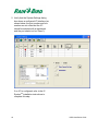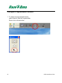
1
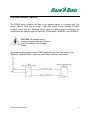
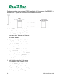
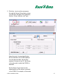
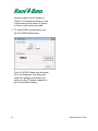
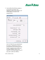
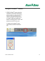
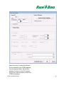
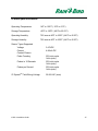
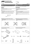
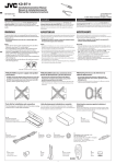
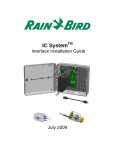
IC System TM ICSEN Sensor Interface Installation Guide August 2015 IMPORTANT NOTES: INSTALLING THE ICSEN – Integrated Control Sensor Interface Device ............................................................................................................................. 3 Compliance Information .................................................................................................. 4 Installation Checklist........................................................................................................ 5 Verify Contents of the Packing Box ................................................................................. 6 Choose Location to Install the ICSEN ............................................................................. 6 Gather Installation Tools ................................................................................................. 7 Connect IC SystemTM Field Wiring .................................................................................. 7 Connect Sensor Source .................................................................................................. 9 Complete Installation ..................................................................................................... 12 Configure Rain Bird Central Control Software ............................................................... 13 Configure Programmable Sensors ................................................................................ 16 Configure Rain WatchTM Sensors.................................................................................. 19 Configure Flo-WatchTM Sensors .................................................................................... 23 ICSEN Specifications: ................................................................................................... 27 2 ICSEN Installation Guide IMPORTANT NOTES: INSTALLING THE ICSEN – Integrated Control Sensor Interface Device This section explains how to install and configure the ICSEN device. NOTE: The ICSEN device must be installed in compliance with all electrical codes. NOTE: The ICSEN device does not provide power for sensor devices. The IC SystemTM wire path MAY NOT be used to power sensor devices. Sensor devices requiring power must be connected to a suitable power source separate from the IC SystemTM wire path. NOTE: The installation of the ICSEN device should be performed with the IC SystemTM wire path unpowered. NOTE: For the first two minutes after the wire path has been reactivated, there will not be any operation or response from the field ICSEN devices. WARNING: Field wire paths must be kept separate from other wire paths. Do not connect the field wires together from different output (group) wire paths on the ICI - Integrated Control Interface WARNING: This appliance is not intended for use by persons (including children) with reduced physical, sensory or mental capabilities, or lack of experience and knowledge, unless they have been given supervision or instruction concerning use of the appliance by a person responsible for their safety. WARNING: Children should be supervised to ensure that they do not play with the appliance. ICSEN Installation Guide 3 Compliance Information E41049 This device complies with Part 15 of the FCC rules subject to the following two conditions: (1) This device may not cause harmful interference, and (2) This device must accept any interference received, including interference that may cause undesired operation. This Class B digital apparatus meets all requirements of the Canadian Interference Causing Equipment Regulations. EN61000-6-1 (1997) Class B: EN61000-3-2 EN61000-3-3 EN61000-6-3 (1996): EN61000-4-2 EN61000-4-3 EN61000-4-4 EN61000-4-5 EN61000-4-6 EN61000-4-8 EN61000-4-11 EN 60335-1: 2010 Safety of household and similar electrical appliances 4 ICSEN Installation Guide Installation Checklist The following steps are recommended in order to properly install the ICSEN device. For your convenience, a check-off box has been provided for each step. Verify the contents of the packing box. Choose a location to install the ICSEN. It is advisable for serviceability to install the ICSEN in a valve box near the target sensor or immediately adjacent to the sensor. Gather installation tools Connect IC SystemTM field wiring Connect sensor source Complete the installation ICSEN Installation Guide 5 Verify Contents of the Packing Box ICSEN Device Choose Location to Install the ICSEN Choose a location minimizing wiring length between ICSEN and target sensor. Ideally the ICSEN should connect directly to the sensor output leads. Choose a location with easy access to the IC SystemTM wire path. Choose a location with easy access to external sensor power needed by your sensor, if any. NOTE: This controller must be installed in compliance with all electrical codes. 6 ICSEN Installation Guide Gather Installation Tools Wire strippers Rain Bird DBRY splice kits (4 total splices) Connect IC SystemTM Field Wiring 1. The ICSEN device should arrive from the factory with wire ends stripped. If not, strip approximately 1” of insulation from each wire. Take care not to score the copper strands. 2. Strip approximately 1” of insulation from each MAXI® wire (IC SystemTM field wiring) to be spliced with ICSEN. Take care not to score copper conductor. 3. Connect the ICSEN (red) wire to the MAXI® (red) wire. Do not connect the ICSEN (red-with-white-stripe) wire at this step. The ICSEN-MAXI® connection should be solid red. ICSEN Installation Guide 7 4. Connect the ICSEN (black) wire to the MAXI® (black) wire. Do not connect the ICSEN (black-with-white-stripe) wire at this step. The ICSEN-MAXI® connection should be solid black. 5. Add suitable protection to the splices. For installation in a valve box, use a Rain Bird DBRY splice kit for each splice, securing the splice with the wire nut then inserting the splice completely into the grease cap. Note that grease caps are single-use; do not attempt to reuse them. 8 ICSEN Installation Guide Connect Sensor Source The ICSEN device monitors the state of an external sensor of a certain type. The sensor state or value can be used in Rain Bird central control software to adjust irrigation, report flow, etc. Although various types of sensors may be connected, the connections are made through the same two ICSEN inputs, SENSOR + and SENSOR -. CAUTION: All electrical wiring connections and wiring runs must be made according to local building codes. The drawing below shows a typical ICSEN application for Rain Can sensing. The SENSOR + and SENSOR – inputs are connected to the Rain Can outputs. ICSEN Installation Guide 9 The drawing below shows a typical ICSEN application for flow sensing. The SENSOR + and SENSOR – inputs are connected to the flow sensor outputs. 1. The ICSEN device should arrive from the factory with wire ends stripped. If not, strip approximately 1” of insulation from each wire. Take care not to score the copper strands. 2. Strip approximately 1” of insulation from each external connection wire to be spliced with ICSEN. Take care not to score copper conductors. 3. Connect the ICSEN (red-with-whitestripe) SENSOR + wire to appropriate sensor output wire. Connect the ICSEN (black-with-white stripe) SENSOR – wire to appropriate sensor output wire. 4. Add suitable protection to the splices. For installation in a valve box, use a Rain Bird DBRY splice kit for each splice, securing the splice with the wire nut then inserting the splice completely into the grease cap. Note that grease 10 ICSEN Installation Guide caps are single-use; do not attempt to reuse them. ICSEN Installation Guide 11 Complete Installation 1. Double-check safety of all connections. Assure that electrical codes have been followed and that no exposed wire ends are present. 2. Assure that ICSEN and the connections are suitably protected from surrounding environment. 3. Note the ICSEN address from the barcode label (or use the tear-off copy of the label) for entry into Rain Bird central control software. 4. If using a sensor with external power supply, apply sensor power. 5. Apply power to the IC SystemTM wire path. Allow two (2) minutes for all IC SystemTM devices on the wire path to power-up before performing operations. 12 ICSEN Installation Guide Configure Rain Bird Central Control Software 1. Launch Rain Bird Central Control software and select System Settings to check ICI configuration: ICSEN Installation Guide 13 2. Verify that the System Settings dialog box shows a configured ICI interface (as shown below; the port number and box number are not critical but the ICI should be selected with a checkmark and the port should not be “Demo”): If no ICI is configured, refer to the IC SystemTM Installation instructions to complete this step. 14 ICSEN Installation Guide 3. There are three “classes” of sensors that you may wish to add to Rain Bird central control: programmable sensors (including flow, level, contact closure, or voltage), Rain WatchTM sensors, and Flo-WatchTM sensors. Programmable sensors can be used for monitoring applications and to trigger central control events like starting a program. Rain WatchTM sensors are used specifically to monitor for rainfall and pause or stop irrigation based on detected rain. Flo-WatchTM sensors are used for flow monitoring and can be used to detect excessive flow conditions due to pipe breaks or other faults. A single ICSEN should not be configured for multiple sensor classes. Doing so will cause operational problems. ICSEN Installation Guide 15 Configure Programmable Sensors 1. To add a new programmable sensor, select Sensors, then the Programmable Sensor tool as shown below: 16 ICSEN Installation Guide 2. Click the + icon to add a new sensor through the Sensor Setup dialog, where you will enter the Name, Box (interface) number, Group, Address, and Type: Name the entry for easy identification. Set the Address to the ICSEN address from the barcode label. Set the Box number (if shown) to the ICI. Set Group to the wire path to which the ICSEN is attached. Set the Sensor Type based on the characteristics of the sensor connected to the ICSEN. For example, a flow meter ICSEN Installation Guide 17 should usually be set for Number of Pulses in 10 Seconds resulting in a rate of flow based on the number of gallons or liters or cubic meters per pulse. 3. To verify ICSEN communication, use the Poll ICSEN Status button. Click Poll ICSEN. Status should indicate OK or No Response. If No Response, check wire path/group, address, and make sure that ICI power is applied for two minutes before testing. 18 ICSEN Installation Guide Configure Rain WatchTM Sensors 1. ICSEN Rain WatchTM sensors should be connected to contact-closure style Rain Cans. To add a new Rain WatchTM sensor, open System Settings: and check the RainWatch checkbox: ICSEN Installation Guide 19 If RainWatch is already active, click the button to open the Rain Can Definition dialog. 20 ICSEN Installation Guide 2. Use the Rain Can Definition window to set the Rain Can Number, Box (interface) number, Group number, and ICSEN address as shown in the example below: Up to four Rain Cans may be defined in the system. Configuration of each is accomplished by first selecting the Rain Can No. using the buttons at the top of the dialog. Set Box number to the correct ICI. Set Group number to the ICI wire path to which the ICSEN is ICSEN Installation Guide 21 connected. Set the Address to the ICSEN barcode address value. Other options are set as normally for the Rain Bird central control software. 3. To verify ICSEN communication, use the Poll ICSEN Status button as shown above. 22 ICSEN Installation Guide Configure Flo-WatchTM Sensors 1. ICSEN Flo-WatchTM sensors should be connected to flow sensors producing a series of pulses at a rate proportional to flow rate. Pulse transmitters can be used to scale pulse rates appropriately for ICSEN. ICSEN can handle input pulses at a maximum rate of 1kHz, 1000 pulses/second at 50% duty cycle. To add a new Flo-WatchTM sensor, select Sensors and the Pulse Sensor tool: ICSEN Installation Guide 23 2. In the Pulse Sensor Monitor window, click the + icon to add a new sensor through the Flow Sensor Setup dialog: 24 ICSEN Installation Guide Name the entry for easy identification. Set the Address to the ICSEN address from the barcode label. Set the Box number (if shown) to the ICI interface. Set Group to the wire path to which the ICSEN is attached. ICSEN Installation Guide 25 Use the Units Per Pulse Calculator to calculate or directly enter the Gallons per Pulse value. Configure Flo-WatchTM and Pump Monitor using normal Rain Bird central control procedures. 3. To verify ICSEN communication, use the Poll ICSEN Status button as shown above. 26 ICSEN Installation Guide ICSEN Specifications: Operating Temperature: 14ºF to 125ºF (-10ºC to 51ºC) Storage Temperature: -40ºF to 150ºF (-40ºC to 65.5ºC) Operating Humidity: 75% max at 40ºF to 108ºF (4.4ºC to 42.2ºC) Storage Humidity: 75% max at 40ºF to 108ºF (4.4ºC to 42.2ºC) Sensor Types Supported Voltage Current Contact Closure Pulse Counting Pulses in 10 Seconds Pulses per Second IC SystemTM Field Wiring Voltage ICSEN Installation Guide 0-10VDC 4-20mA DC 50% duty cycle 1kHz (max) 50% duty cycle 1kHz (max) 50% duty cycle 1kHz (max) 26-28 VAC (max) 27