1
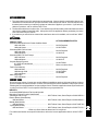
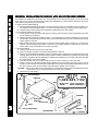
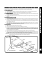
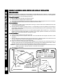
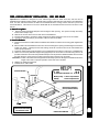
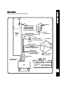
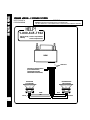
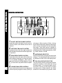
AV-990
DIGITALAM/FM/MPXRADIOWITH
AUTO-REVERSECASSETTEPLAYER
3-BANDGRAPHICEQUALIZER
AND QUARTZ CLOCK
INDEX
How To Use This Manual ................................................................. Page 1
Kit Information .................................................................................. Page 2
Universal and Import Car Installations ............................................. Pages 3,4
Chevrolet-Oldsmobile-Pontiac-Buick-GMC-Cadillac-Saturn
Installations......................................................................... Pages 5,6
Ford-Lincoln-Mercury Installations ................................................... Pages 7,8
Chrysler-Dodge-Plymouth Installations ............................................ Page 9
Radio Wiring ..................................................................................... Page 10
Speaker Wiring- 2 Speaker Systems................................................ Page 11
4 Speaker Systems................................................ Page 12
Operating Instructions ...................................................................... Pages 13-15
Setting the Clock .............................................................................. Page 15
Specifications ................................................................................... Page 16
Troubleshooting ............................................................................... Page 17
Care and Maintenance ..................................................................... Page 18
Warranty ........................................................................................... Back Cover
Toll-Free Assistance
The installation and wiring connections for this unit are so simple, we doubt you'll need
our help, but, if you do, we're here to help you. Just call our toll-free assistance line
at (800) 645-7102 during days/hours shown.
TIME ZONE
DAY
MON.-FRI.
SATURDAY
PACIFIC
MOUNTAIN
5:30AM - 4PM
6AM - 2PM
6:30AM - 4PM
7AM - 3PM
CENTRAL
7:30AM - 6PM
8AM - 4PM
EASTERN
8:30AM - 7PM
9AM - 5PM
HELP!
1-800-645-7102
Monday-Friday 8:30am-7:00pmEastern
Saturday
9:00am-5:00pmEastern
HOW TO USE THIS MANUAL
1
1.
2.
3.
4.
Identify the make and year of the car in which you will be installing this sound system.
Refer to the Kit Listing and Kit Information sections on page 2 to determine if a kit is required.
If a kit is required, follow the directions in Kit Information section.
Follow the specific installation instructions for your particular make of car as listed in the
index.
KITINFORMATION
1. The years shown in the Kit Listing below are approximate. Always check the application chart at your
retail store to find information on your specific make, model, and year of vehicle. If a kit is required, read
the description on the kit you intend to purchase to make sure it applies to your vehicle. If you have any
doubts or questions, call our toll-free "HELP" line.
2. The kits shown below are Audiovox kits. Your retailer may sell kits made by other manufacturers which
may also be usable to install this radio. Always check the kit application before purchasing it to make
sure it will work with your vehicle.
3. If you believe you need a kit but cannot find a retail store where it is available, call our toll-free "HELP"
line.
KITLISTING
VEHICLE TYPE
Chevrolet-Oldsmobile-Buick-Pontiac-Cadillac-Saturn
1981 and Older ...............................................................
1982 and Newer ..............................................................
Chevrolet-GMC Full Size Vans
1987 and Older ...............................................................
1988 and Newer ...............................................................
Chevrolet-GMC Full Size Pickups
1987 and Older ...............................................................
1988 and Newer ...............................................................
Chrysler-Dodge-Plymouth
U.S. Built 1974 and Newer ...............................................
Imported ..........................................................................
Ford-Lincoln-Mercury
1984 and Older ................................................................
1985 through 1990 ...........................................................
1991 and Newer ...............................................................
AMC-Jeep-Eagle
1971 and Newer ...............................................................
KIT REQUIREMENT/NOTES
No Kit Required
AX-93-FCGM
No Kit Required
AX-88-CHV
No Kit Required
AX-88-CHT
AX-93-FCGM
Refer to In-Store Chart
No Kit Required
AX-93-FCGM
AX-88-SNP
No Kit Required
IMPORT CARS
Due to the wide variety of import cars and the different installations required, this manual does not show
specific installations in these vehicles. However, this sound system can be installed in many import cars by
following the "Universal Installation" section on pages 3 and 4. Check the application chart at your retail store
or call our toll-free "HELP" line for specific information on your particular car.
IMPORTS:
Acura-Audi-BMW-Daihatsu-Fiat-Honda-Hyundai
Mercedes-Peugeot-Porsche-Saab-Subaru
Volkswagen-Volvo-Yugo .............................................. Will Fit Most Years; Some Require AX-88-SNP Kit *
Datsun-Nissan (Most Models)
1982 and Newer ................................................... Will Fit Most Years; Some Require AX-88-NAB Kit *
Mazda (Most Models)
1986 and Newer ................................................... Will Fit Most Years; Some Require AX-87-MAZ Kit *
Toyota (Most Models)
1982 and Newer ................................................... Will Fit Most Years; Some Require AX-88-TOY Kit *
* Refer to In-Store Chart to determine if kit is required.
For vehicles not listed or more specific information, refer to the in-store application chart or call our "HELP"
line.
2
UNIVERSAL AND IMPORT CAR INSTALLATION
UNIVERSAL INSTALLATION FOR VEHICLES WITH AN EXISTING RADIO OPENING
This installation is designed for cars, trucks, vans, and boats that have an existing radio opening. It can also be used
as an option on some of the vehicles listed as requiring the AX-88-SNP kit. It will not work on all vehicles, but can be
used on most newer Fords and many imports.
1.InspecttheExistingRadioOpening:
A. Use the trimplate supplied with the radio to cover the existing opening. If it completely covers the opening, you
can install the radio as explained below. If it does not cover the opening, you will need an installation kit.
B. Check that there will be sufficient space behind the dashboard for the radio chassis.
2.WiretheRadiototheVehicle'sWiring:
A. In most cases it is easier to wire the radio before mounting it. Place the radio near the dashboard so the wires
can be led through the opening.
B. Carefully follow the diagrams on pages 10 and 11 or 12 (depending on how many speakers you are using) to
wire the radio, making certain all connections are secure and insulated with wire nuts or electrical tape to insure
proper operation of the unit.
C. After completing the wiring, turn the unit on to confirm operation (ignition switch must be "on"). If unit does not
operate, re-check all wiring until problem is corrected. Once proper operation is achieved, turn off unit and
ignition switch, and proceed with final mounting of the radio.
3. MountingtheRadio:
A. Thread a shaft nut half-way down each radio shaft.
B. Place a metal back-up plate on each radio shaft against the shaft nut.
C. Position the radio behind the dashboard opening so that the back-up plates are snug against the back of the
opening. Adjust the shaft nuts behind the back-up plates so that the desired amount of radio extends through
the opening. If possible, the best appearance is usually achieved when there is enough of the radio extending
to be flush with the front of the trimplate.
D. Place the trimplate over the front of the radio and secure it with a shaft nut on each radio shaft.
E. Attach one end of the perforated support strap (supplied) to the screw stud on the radio using the hex nut
provided. Fasten the other end of the perforated strap to a secure part of the dashboard either above or below
the radio using the screw and nut provided. Bend the strap to position it as necessary.
CAUTION: The rear of the radio must be supported with the strap to prevent damage to the dashboard from the
weight of the radio or improper operation of the radio due to vibration.
F. Install knobs on radio shafts.
PERFORATEDSTRAP
SCREWSTUD
HEXNUT
RADIO
SCREW
HELP!
1-800-645-7102
Monday-Friday 8:30am-7:00pmEastern
Saturday
9:00am-5:00pmEastern
SHAFTNUT
DASHBOARD
METALPARTOF
DASHBOARD
BACK-UPPLATE
HEXNUT
3
DRILLHOLEIFNECESSARY
TRIMPLATE
EXISTINGOPENING
SHAFTNUTS
UNIVERSALINSTALLATION FOR VEHICLES WITHOUT AN EXISTING RADIO OPENING
1.SelecttheMountingArea:
A. Using the trimplate supplied, verify that there will be sufficient space on the selected mounting surface.
B. Check that there will be sufficient space behind the dashboard for the radio chassis.
2. CuttheRequiredOpening:
A. Using the trimplate as a template, place it on the selected mounting surface and mark the 2 shaft holes and
nosepiece opening that will need to be cut.
B. Carefully cut the 3 holes using a drill and keyhole saw as appropriate. File edges of the openings to remove
any burrs.
3.WiretheRadiototheVehicle'sWiring:
A. In most cases it is easier to wire the radio before mounting it. Place the radio near the dashboard so the wires
can be led through the opening.
B. Carefully follow the diagrams on pages 10 and 11 or 12 (depending on how many speakers you are using) to
wire the radio, making certain all connections are secure and insulated with wire nuts or electrical tape to insure
proper operation of the unit.
C. After completing the wiring, turn the unit on to confirm operation (ignition switch must be "on"). If unit does
not operate, re-check all wiring until problem is corrected. Once proper operation is achieved, turn off unit and
ignition switch, and proceed with final mounting of the radio.
4.Mountingtheradio:
A. Thread a shaft nut half-way down each radio shaft.
B. Place a metal back-up plate on each radio shaft against the shaft nut.
C. Position the radio behind the dashboard opening so that the back-up plates are snug against the back of the
opening. Adjust the shaft nuts behind the back-up plates so that the desired amount of radio extends through
the opening. If possible, the best appearance is usually achieved when there is enough of the radio extending
to be flush with the front of the trimplate.
D. Place the trimplate over the front of the radio and secure it with a shaft nut on each radio shaft.
E. Attach one end of the perforated support strap (supplied) to the screw stud on the radio using the hex nut
provided. Fasten the other end of the perforated strap to a secure part of the dashboard either above or below
the radio using the screw and nut provided. Bend the strap to position it as necessary.
CAUTION: The rear of the radio must be supported with the strap to prevent damage to the dashboard from the
weight of the radio or improper operation of the radio due to vibration.
F. Install knobs on radio shafts.
HEXNUT
UNIVERSAL AND IMPORT CAR INSTALLATION
This installation is designed for cars, trucks, vans, and boats that do not have an existing radio opening. It will require
cutting an opening in a surface of the vehicle, so it is important to mark and measure carefully.
PERFORATEDSTRAP
SCREWSTUD
RADIO
SCREW
SHAFTNUT
CUTOPENING
METALPARTOF
DASHBOARD
BACK-UPPLATE
HEXNUT
DRILLHOLEIFNECESSARY
DASHBOARD
TRIMPLATE
SHAFTNUTS
4
CHEVROLET-OLDS-BUICK-PONTIAC-GMC-CADILLAC INSTALLATION
CHEVROLET-OLDSMOBILE-BUICK-PONTIAC-GMC-CADILLAC INSTALLATION
1981 AND OLDER
Important-This installation is designed for 1981 and older U.S. made GM cars, trucks, and vans. For 1981 and newer
vehicles, an installation kit may be required. See Kit Listing on Page 2 of this manual or refer to the in-store application
chart. If a kit is not required, use the following instructions.
1. RemoveExistingRadio:
A.
B.
C.
D.
Remove radio knobs and shaft nuts behind the knobs.
Locate and remove support brace at back of radio.
Push radio back into dashboard to access the wiring and antenna cables plugged into the rear of the chassis.
Un-plug the wiring harness(es) and antenna cable and remove the radio.
2. WiretheNewRadio:
A. In most cases it is easier to wire the radio before mounting it. Place the radio near the dashboard so the wires
can be led through the opening.
B. Carefully follow the diagrams on pages 10 and 11 or 12 (depending on how many speakers you are using) to
wire the radio, making certain all connections are secure and insulated with wire nuts or electrical tape to insure
proper operation of the unit.
C. After completing the wiring, turn the unit on to confirm operation (ignition switch must be "on"). If unit does not
operate, re-check all wiring until problem is corrected. Once proper operation is achieved, turn off unit and
ignition switch, and proceed with final mounting of the radio.
3.InstalltheNewRadio:
A. Thread a shaft nut half-way down each radio shaft.
B. Trim the top edge off of the nosepiece collar at the "CUT OFF FOR GM" mark and place the collar on radio
nosepiece.
C. Place the radio behind dashboard and through the radio opening. Adjust the position of the shaft nuts so that
the radio nosepiece and collar are flush against the back of the dashboard.
D. Secure the radio with a shaft nut on each radio shaft.
E. Attach one end of the perforated support strap (supplied) to the screw stud on the radio using the hex nut
provided. Fasten the other end of the perforated strap to a secure part of the dashboard either above or below
the radio using the screw and nut provided. Bend the strap to position it as necessary.
CAUTION: The rear of the radio must be supported with the strap to prevent damage to the dashboard from the
weight of the radio or improper operation of the radio due to vibration.
F. Install knobs on radio shafts.
HEXNUT
PERFORATEDSTRAP
SCREWSTUD
RADIO
HELP!
1-800-645-7102
Monday-Friday 8:30am-7:00pmEastern
Saturday
9:00am-5:00pmEastern
SCREW
TRIMFOR"GM"
METALPARTOF
DASHBOARD
HEXNUT
5
DRILLHOLEIFNECESSARY
SHAFTNUT
NOSEPIECECOLLAR
(INCLUDEDWITHRADIO)
DASHBOARD
SHAFTNUTS
Important-This installation is designed for most 1982 and newer GM cars, trucks, and vans where an installation kit
is required. See Kit Listing on Page 2 of this manual or refer to the in-store application chart. If a kit is not required,
use the instructions on Page 5.
1. RemoveExistingRadio:
A. Remove the existing dashboard trimpanel surrounding the radio opening. This panel is usually secured by
screws and/or snap-in clips.
B. Remove the screws used to secure the radio to the sub-dashboard.
C. Pull the radio forward to access the wiring and antenna cables plugged into the rear of the chassis.
D. Un-plug the wiring harness(es) and antenna cable and remove the radio.
2.InstalltheNewRadio:
A. Follow the instructions included with the installation kit to attach the radio to the mounting plate supplied with
the kit.
B. Place the radio near the dashboard so the wires can be led through the opening and following the instructions
of Step 2 on Page 5, carefully wire the radio making certain all connections are secure and insulated and confirm
proper operation.
C. Install the radio/mounting plate assembly to the sub-dashboard according to instructions of installation kit.
D. Attach one end of the perforated support strap (supplied) to the screw stud on the radio using the hex nut
provided. Fasten the other end of the perforated strap to a secure part of the dashboard either above or below
the radio using the screw and nut provided. Bend the strap to position it as necessary.
CAUTION: The rear of the radio must be supported with the strap to prevent damage to the dashboard from the
weight of the radio or improper operation of the radio due to vibration.
E. Replace the dashboard trimpanel.
F. Install knobs on radio shafts.
HEXNUT
PERFORATEDSTRAP
SCREWSTUD
RADIO
SCREW
HEXNUT
MOUNTINGPLATEFROMKIT
(NOTINCLUDEDWITHRADIO)
IMPORTANT
AMOUNTINGKITISREQUIRED
FORTHISINSTALLATION
SHAFTNUT
EXISTINGDASHTRIMPANEL
CHEVROLET-OLDS-BUICK-PONTIAC-GMC-CADILLAC-SATURN INSTALLATION
CHEVROLET-OLDSMOBILE-BUICK-PONTIAC-GMC-CADILLAC-SATURN INSTALLATION
1982 AND NEWER
6
FORD-LINCOLN-MERCURY INSTALLATION
FORD-LINCOLN-MERCURY INSTALLATION - 1984ANDOLDER
Important-This installation is designed for 1984 and older U.S. made Ford cars, trucks, and vans. For newer
vehicles, an installation kit may be required. See Kit Listing on Page 2 of this manual or refer to the in-store chart.
1. RemoveExistingRadio:
A.
B.
C.
D.
Remove radio knobs and shaft nuts behind the knobs.
Locate and remove support brace at back of radio.
Push radio back into dashboard to access the wiring and antenna cables plugged into the rear of the chassis
Un-plug the wiring harness(es) and antenna cable and remove the radio.
2. WiretheNewRadio:
A. In most cases it is easier to wire the radio before mounting it. Place the radio near the dashboard so the wires
can be led through the opening.
B. Carefully follow the diagrams on pages 10 and 11 or 12 (depending on how many speakers you are using)
to wire the radio, making certain all connections are secure and insulated with wire nuts or electrical tape to
insure proper operation of the unit.
C. After completing the wiring, turn the unit on to confirm operation (ignition switch must be "on"). If unit does
not operate, re-check all wiring until problem is corrected. Once proper operation is achieved, turn off unit
and ignition switch, and proceed with final mounting of the radio.
3.InstalltheNewRadiio:
A. Thread a shaft nut halfway down each radio shaft.
B. Place the nosepiece collar on the radio nosepiece.
C. Place the radio behind dashboard and through the radio opening. Adjust the position of the shaft nuts so that
the radio nosepiece and collar are flush against the back of the dashboard.
D. Secure the radio with a shaft nut on each radio shaft.
E. Attach one end of the perforated support strap (supplied) to the screw stud on the radio using the hex nut
provided. Fasten the other end of the perforated strap to a secure part of the dashboard either above or below
the radio using the screw and nut provided. Bend the strap to position it as necessary.
CAUTION: The rear of the radio must be supported with the strap to prevent damage to the dashboard from the
weight of the radio or improper operation of the radio due to vibration.
F. Install knobs on radio shafts.
HEXNUT
PERFORATEDSTRAP
SCREWSTUD
RADIO
SCREW
NOSEPIECECOLLAR
(INCLUDEDWITHRADIO)
METALPARTOFDASHBOARD
HEXNUT
7
IMPORTANT
AMOUNTINGKITISREQUIRED
FORTHISINSTALLATION
DRILLHOLEIF
NECESSARY
DASHBOARD
SHAFTNUTS
Important-This installation is designed for most 1985 through 1990 U.S. made Ford cars, and vans and an
installation kit is required for these vehicles. See Kit Listing on Page 2 of this manual or refer to the in-store application
chart. For 1991 and newer vehicles, the radio can be installed as shown on Page 3 of this manual or you can use
the AX-88-SNP kit. Instructions for use of the AS-88-SNP kit are included with the kit and are not shown in this
manual.
1. RemoveExistingRadio:
A.
Remove existing dashboard trimpanel surrounding the radio opening. This panel is usually secured by
screws and/or snap-in clips.
B. Remove the screws used to secure radio to the sub-dashboard.
C. Pull the radio forward to access the wiring and antenna cables plugged into the rear of the chassis.
D. Un-plug the wiring harness(es) and antenna cable and remove the radio.
2.InstalltheNewRadio:
A. Follow the instructions included with the installation kit to attach the radio to the mounting plate supplied with
the kit.
B. Place the radio near the dashboard so the wire can be led through the opening and following the instructions
of Step 2 on Page 7, carefully wire the radio making certain all connections are secure and insulated and
confirm proper operation.
C. Install the radio/mounting plate assembly to the sub-dashboard according to instructions of installation kit.
D. Attach one end of the perforated support strap (supplied) to the screw stud on the radio using the hex nut
provided. Fasten the other end of the perforated strap to a secure part of the dashboard either above or below
the radio using the screw and nut provided. Bend the strap to position it as necessary.
CAUTION: The rear of the radio must be supported with the strap to prevent damage to the dashboard from the
weight of the radio or improper operation of the radio due to vibration.
E. Replace the dashboard trimpanel.
F. Install knobs on radio shafts.
FORD-LINCOLN-MERCURY INSTALLATION
FORD-LINCOLN-MERCURY INSTALLATION - 1985 AND NEWER
HELP!
PERFORATEDSTRAP
SCREWSTUD
HEXNUT
1-800-645-7102
Monday-Friday 8:30am-7:00pmEastern
Saturday
9:00am-5:00pmEastern
RADIO
MOUNTINGPLATEFROMKIT
(NOTINCLUDEDWITHRADIO)
SCREW
HEXNUT
IMPORTANT
AMOUNTINGKITISREQUIRED
FORTHISINSTALLATION
SHAFTNUTS
EXISTINGDASHTRIMPANEL
8
CHRYSLER-DODGE-PLYMOUTH INSTALLATION
CHRYSLER-DODGE-PLYMOUTH INSTALLATION
ALLU.S.MADECARS,TRUCKS,ANDVANSBUILTSINCE
1974
ALLU.S.MADECARS,TRUCKS,ANDVANSBUILTSINCE1974
Important-This radio cannot be installed in any U.S. made Chrysler, Dodge, or Plymouth vehicle without an
installation kit. Refer to the Kit Listing on Page 2 for the required kit. Complete kit installation is explained in the
instructions included with the kit.
1. RemoveExistingRadio:
A. Remove the existing dashboard trimpanel surrounding the radio opening. This panel is usually secured by
screws and/or snap-in clips.
B. Remove the two large screws used to secure radio to the sub-dashboard.
C. Pull the radio forward to access the wiring and antenna cables plugged into the rear of the chassis.
D. Un-plug the wiring harness(es) and antenna cable and remove the radio.
2.InstalltheNewRadio:
A. Follow the instructions included with the installation kit to attach the radio to the mounting plate supplied with
the kit.
B. Place the radio near the dashboard so the wires can be led through the opening and following the instructions
of Step 2 on Page 3, carefully wire the radio making certain all connections are secure and insulated and
confirm proper operation.
C. Install the radio/mounting plate assembly to the sub-dashboard according to instructions of installation kit.
D. Attach one end of the perforated support strap (supplied) to the screw stud on the radio using the hex nut
provided. Fasten the other end of the perforated strap to a secure part of the dashboard either above or below
the radio using the screw and nut provided. Bend the strap to position it as necessary.
CAUTION: The rear of the radio must be supported with the strap to prevent damage to the dashboard from the
weight of the radio or improper operation of the radio due to vibration.
E. Replace the dashboard trimpanel.
F. Install knobs on radio shafts.
HELP!
1-800-645-7102
PERFORATEDSTRAP
HEXNUT
Monday-Friday 8:30am-7:00pmEastern
Saturday
9:00am-5:00pmEastern
SCREWSTUD
RADIO
SCREW
SHAFTNUT
HEXNUT
9
IMPORTANT
AMOUNTINGKITISREQUIRED
FORTHISINSTALLATION
MOUNTINGPLATEFROMKIT
(NOTINCLUDEDWITHRADIO)
EXISTINGDASHTRIMPANEL
RADIO WIRING
RADIO WIRING
REFERTOPAGE11OR12 FORSPEAKERWIRING
ANTENNA
AUTOMATIC
ANTENNA
PINK
IMPORTANT
THEPINKWIRECANBEUSED
TOREMOTELYACTIVATEAN
AUTOMATICANTENNAORAN
EXTERNALAMPLIFIER(SEE
ANTENNAORAMPLIFIERMANUAL).
EXISTING
ANTENNA
CABLE
FUSEBLOCK
"RADIO"OR
"ACCESSORY"FUSE
ORANGEw/WHITESTRIPE
BLACKw/WHITESTRIPE
SCREW
METALPARTOFDASH
(DRILLHOLEIFNECESSARY)
CARBATTERY
GREENw/WHITESTRIPE
IMPORTANT
THISWIREMUSTBECONNECTEDASSHOWN
ORRADIOWILLNOTOPERATEPROPERLY
SEEPAGE11OR12
FORSPEAKERWIRING
(RED,YELLOW,WHITE,BLUE,
VIOLET,&LIGHTGREEN)
POSITIVE(+)TERMINAL
12VOLTBATTERY
9PINPLUGS
HELP!
ANTENNASOCKET
ONREAROFRADIO
1-800-645-7102
RADIO
Monday-Friday 8:30am-7:00pmEastern
Saturday
9:00am-5:00pmEastern
10
SPEAKER WIRING
SPEAKER WIRING - 2 SPEAKER SYSTEMS
WARNING!
REFERTOPAGE10
FORRADIOWIRING
NEVERGROUNDNEGATIVESPEAKERLEADSTOCHASSISGROUND.
FAILURETOWIREEXACTLYASSHOWNBELOWMAYCAUSEELECTRICALDAMAGETOTHERADIO.
HELP!
1-800-645-7102
Monday-Friday 8:30am-7:00pmEastern
Saturday
9:00am-5:00pmEastern
RADIO
9PINPLUGS
SEEPAGE10FORRADIOWIRING
(BLACKw/WHITESTRIPE,
ORANGEw/WHITESTRIPE,
GREENw/WHITESTRIPE&PINK)
DRIVER'SSIDE
(LEFT)SPEAKER
PASSENGER'SSIDE
(RIGHT)SPEAKER
WHITE
SPLICE
11
RED
VIOLET
BLUE
YELLOW
LIGHTGREEN
SPLICE
REFERTOPAGE10
FORRADIOWIRING
WARNING!
NEVERGROUNDNEGATIVESPEAKERLEADSTOCHASSISGROUND.
FAILURETOWIREEXACTLYASSHOWNBELOWMAYCAUSEELECTRICALDAMAGETOTHERADIO.
HELP!
1-800-645-7102
SPEAKER WIRING
SPEAKER WIRING - 4 SPEAKER SYSTEMS
Monday-Friday 8:30am-7:00pmEastern
Saturday
9:00am-5:00pmEastern
RADIO
SEEPAGE10FORRADIOWIRING
(BLACKw/WHITESTRIPE,
ORANGEw/WHITESTRIPE,
GREENw/WHITESTRIPE&PINK)
9PINPLUGS
DRIVER'SSIDE
LEFTFRONTSPEAKER
PASSENGER'SSIDE
RIGHTFRONTSPEAKER
WHITE
SPLICE
VIOLET
RED
11
DRIVER'SSIDE
LEFTREARSPEAKER
BLUE
LIGHTGREEN
SPLICE
YELLOW
PASSENGER'SSIDE
RIGHTREARSPEAKER
12
OPERATING INSTRUCTIONS
OPERATING INSTRUCTIONS
1
q
b5
3
6 bl br 8 o
b
n
bm
b
9
1
ON-OFF SWITCH/VOLUME CONTROL
Rotate this knob to the right to turn the unit on.
Continue rotation until desired volume level is
obtained.
2 LEFT/RIGHT BALANCE CONTROL
Rotate this knob to the left or right to obtain the
desired balance between the left and right channel speakers.
3 FRONT/REAR FADER CONTROL
Rotate this knob to the right or left to obtain the
desired balance between front and rear speakers in 4 speaker installations. When used in
conjunction with the Left/Right Balance Control
, you have full 4-way stereo balance capability.
2
13
4
3-BAND EQUALIZER CONTROLS
These controls permit precise tone adjustment
in three frequency ranges from bass (100 Hz) to
b
s bt 4
7
p
b 2
mid-range (1 KHz) to treble (10 KHz). Moving
each control upward will emphasize that range,
while moving it downward will de-emphasize
that range. Each slide control is capable of
varying the response from the mid-position (flat)
setting upward by 12 dB or downward by 12 dB,
for a total variation of 24 dB.
5 AM/FM BAND SELECTOR
Each time this button is pressed, the radio band
changes. The selected radio band is shown by
the indicator for AM or FM on the display panel.
6
FM LOCAL/DISTANT SELECTOR
This two position switch is incorporated to allow
maximum reception in both weak and strong
FM signal areas. For normal reception conditions when receiving a wide range of signals
including weak or distant stations, the switch
should be in the released (out) position, which
7 MANUAL TUNING CONTROL
Rotate this knob to the left or right to select a
radio station. The selected frequency will be
shown by the digital read-out on the display
panel.
8 AM ANTENNA TRIMMER
It is very imporatnt to adjust the Antenna Trimmer for optimum AM reception. The antenns
trimmer is located at the back of the cassette
deck behind the the tape door. Adjust it as
follows:
1. Tune in a weak station around 1400 KHz on
the AM band.
2. Push the tape door open and locate the
antenna trimmer at the back of the cassette deck.
3. Using a small screwdriver, slowly adjust the
trimmer for maximum output from the radio.
NOTE: The Antenna Trimmer only affects AM
reception, and will have no effect on
FM reception. The trimmer only needs
to be adjusted when the radio is first
installed and at any time a change is
made to the vehicle antenna (replacing
the mast, etc.).
9 DISPLAY PANEL
The digital display of the radio frequency and
time are shown on this panel as well as indicators for AM, FM, and stereo reception.
bl CASSETTE DOOR
Hold the cassette with the exposed tape edge to
the right and insert it into the cassette door.
Depress fully until the cassette is engaged and
begins playing. When the cassette reaches the
end of the side of the tape being played, the unit
will automatically change direction of play, as
shown by the Tape Direction Indicators
, and
play the other side of the cassette.
bp
bm
OPERATING INSTRUCTIONS
will allow maximum signal to the receiver. When
in an extremely strong (local) signal area, push
the switch in to the Local setting. This will
eliminate weak signals and suppress overly
strong signals so as to avoid overloading the
receiver input. When moving out of the strong
signal area, return the switch to the Distant (out)
setting.
NOTE: The Local/Distant Selector only affects
FM signals, and will have no effect on
AM reception.
FAST-FORWARDBUTTON(FF)
Pushing the Fast-Forward button will cause the
tape to move rapidly in the forward direction of
play. To stop Fast-Forward movement, lightly
push the Rewind button
until the Fast-Forward button disengages.
bn
bn REWINDBUTTON(REW)
Pushing the Rewind button will cause the tape to
move rapidly in the reverse direction of play. To
stop Rewind movement, lightly push the FastForwardbutton
untiltheRewindbuttondisengages.
bm
bo PROGRAMSELECTOR
To manually reverse tape direction and play the
other side of the cassette, lightly push both the
Fast-Forward
andRewind
buttonsatthe
same time. The change of direction will be
shown by the Tape Direction Indicators
.
bm
bn
bp
bp TAPEDIRECTIONINDICATORS
These arrows show the direction of tape play
and will change when the program is changed
either automatically at the end of play on one
side of the cassette or manually by the Program
Selector
.
bo
14
OPERATING INSTRUCTIONS
bq
EJECT BUTTON ( )
Tape playback is stopped and the cassette is
ejected by pressing this button, which also has
the function of switching over to radio operation.
NOTE: Never leave a cassette engaged in the
player when not in use. Doing so can
cause damage to the cassette and/or
mechanism. Always press the eject
button and remove the cassette when
leaving the vehicle.
br DISPLAY CALL SELECTOR (CALL)
During radio operation, the station frequency
will be shown on the display panel. Pressing
this button will cause the time to be displayed for
5 seconds before returning to frequency readout.
bs
HOUR ADJUST BUTTON (H)
This button is used to adjust the hours on the
built-in quartz clock. The button is recessed to
prevent accidental engagement so a toothpick,
pen point or similar object should be used to
activate it.
bt
MINUTE ADJUST BUTTON (M)
This button is used to adjust the minutes on the
built-in quartz clock. The button is recessed to
prevent accidental engagement so a toothpick,
pen point or similar object should be used to
activate it.
During cassette operation, the time will always
be shown on the display panel.
SETTINGTHECLOCK
1. With the vehicle ignition switch “on”, turn the unit off or insert a cassette into the tape door so
that the time is showing on the display panel.
2. Using a toothpick, pen point or similar thin object, press the Hour Adjust button
hours to the correct setting.
bs to adjust the
3. Using a toothpick, pen point or similar thin object, press the Minute Adjust button
the minutes to the correct setting.
15
bt to adjust
Size:
7" W x 2" H x 5-1/2" D
178mm x 50mm x 137mm
Operating Voltage:
12 volts DC, negative ground
Output Power:
50 watts maximum
( 25 watts x 2 channels)
Output Wiring:
Floating-ground type designed for 4 speaker use.
May also be used with 2 speakers.
Output Impedance:
Compatible with 4-8 ohm speakers
Tuning Range:
AM: 530-1,720 KHz.
FM: 87.5-107.9 MHz.
Sensitivity:
AM: 15 uv.
FM: 2.5 uv.
FM Stereo Separation:
30 dB
Tape Frequency Response:
50-10,000 Hz.
Tape S/N Ratio:
50 dB
Wow & Flutter:
0.15% WRMS
SPECIFICATIONS
SPECIFICATIONS
* Specifications are subject to change without notice.
16
TROUBLESHOOTING
TROUBLESHOOTING
PROBLEM
PROBABLE CAUSE
CHECK FOLLOWING
Incorrect power connection
Orange/White stripe wire to +12V
ACC. and Green/White stripe wire
to +12V battery
Blown fuse
Check fuses in wires listed above
and check car fuse block
Incorrect power connection
Green/White Stripe wire is not connected to a "live" +12V battery
source
Blown fuse
Check fuse in Green/White stripe
wire and at car's fuse block
Poor ground
Check Black/White stripe wire for
proper grounding
Dirty or corroded battery posts
Clean and tighten connection
If problem also existed with previous radio you removed
Consult your local garage mechanic-car may need tune-up or
noise filter
Noise on radio only
Antenna
Check that antenna base is
grounded. Test with antenna disconnected. If noise goes away,
replace antenna
Poor FM reception and almost no
AM reception
Antenna
Replace antenna and antenna
cable
Poor FM reception and Good AM
reception
FM Local-Distant switch
Check if unit has a Local-Distant
switch and set to "Distant" position
No sound on one speaker
(both radio and tape)
Wiring
Check speaker wiring
Speaker
Test with good speaker
Radio Operation
Check balance and fader controls
Poor sound on tape only (after
one month or more of tape usage)
Dirty tape mechanism
Clean tape head and mechanism
Poor sound-new unit
For radios with 40 watts or more
output power
Check rating of speakers for sufficient power capacity
Unit completely inoperative no
lights, no sound
Unit will not keep time or Radio
station memory
(Electronic Tuning Radios Only)
Noise on both radio and tape
Check that speakers are in good
condition
17
Check that Violet and Green
speaker wires are not grounded
Wiring
Check speaker wiring
The radio portion of your new sound system does not require any maintenance. We
recommend you keep this manual for future reference on how to set the clock (on units
with a clock) and for general reference of the many features found in this unit.
As with any cassette player, the cassette section of this sound system does require a
minimum of maintenance to keep it in good working condition. The following simple care
and maintenance suggestions should be followed to prevent malfunctions of the cassette
system.
CassetteCare:
1. Purchase a cassette cleaning kit from your local retail store. Use it! At least every
20 to 30 hours of operation you must clean the cassette mechanism. A dirty
cassette player will have a poor sound.
2. Do not use cassettes that exceed 45 minutes of play on each side.
3. Do not insert a cassette that appears to be broker, twisted or dirty or with loose or
torn labels on it.
4. Always keep your cassettes away from direct sunlight or exposure to sub-freezing
conditions. If a cassette is cold, allow it to warm up before use.
5. Do not keep a cassette in the player when not in use.
6. Before inserting a cassette in the player, check that the tape is tightly wound on the
reels. Take up any excess slack using a pencil to turn the drive hub in the cassette
(see diagram below).
CARE AND MAINTENANCE
CARE AND MAINTENANCE
18
12 MONTH LIMITED WARRANTY
Applies to In-dash radios, radio/tape player and radio/CD player combinations, and CD Changers.
AUDIOVOX CORPORATION (the Company) warrants to the original retail purchaser of this product that should this
product or any part thereof, under normal use and conditions, be proven defective in material or workmanship within
12 months from the date of original purchase, such defect(s) will be repaired or replaced with new or reconditioned
product (at the Company's option) without charge for parts and repair labor.
To obtain repair or replacement within the terms of this Warranty, the product is to be delivered with proof of warranty
coverage (e.g. dated bill of sale), specification of defect(s), transportation prepaid, to an approved warranty station.
For the location of the nearest warranty station to you, call toll-free to our control office:
IN U.S.A.
1-800-243-1311
IN CANADA 1-800-645-4994
This Warranty does not extend to the elimination of car static or motor noise, to correction of antenna problems, to
costs incurred for installation, removal, or reinstallation of the product, or damage to tapes, compact discs, speakers,
accessories, or vehicle electrical systems.
This Warranty does not apply to any product or part thereof which, in the opinion of the Company, has suffered or
been damaged through alteration, improper installation, mishandling, misuse, neglect, accident, or by removal or
defacement of the factory serial number/bar code label(s). THE EXTENT OF THE COMPANY'S LIABILITY UNDER
THIS WARRANTY IS LIMITED TO THE REPAIR OR REPLACEMENT PROVIDED ABOVE AND, IN NO EVENT,
SHALL THE COMPANY'S LIABILITY EXCEED THE PURCHASE PRICE PAID BY PURCHASER FOR THE
PRODUCT.
This Warranty is in lieu of all other express warranties or liabilities. ANY IMPLIED WARRANTIES, INCLUDING ANY
IMPLIED WARRANTY OF MERCHANTABILITY, SHALL BE LIMITED TO THE DURATION OF THIS WRITTEN
WARRANTY. ANY ACTION FOR BREACH OF ANY WARRANTY HEREUNDER INCLUDING ANY IMPLIED
WARRANTY OF MERCHANTABILITY MUST BE BROUGHT WITHIN A PERIOD OF 30 MONTHS FROM DATE OF
ORIGINAL PURCHASE. IN NO CASE SHALL THE COMPANY BE LIABLE FOR ANY CONSEQUENTIAL OR
INCIDENTAL DAMAGES FOR BREACH OF THIS OR ANY OTHER WARRANTY, EXPRESS OR IMPLIED,
WHATSOEVER. No person or representative is authorized to assume for the Company any liability other than
expressed herein in connection with the sale of this product.
Some states do not allow limitations on how long an implied warranty lasts or the exclusion or limitation of incidental
or consequential damage so the above limitations or exclusions may not apply to you. This Warranty gives you
specific legal rights and you may also have other rights which vary from state to state.
U.S.A. : AUDIOVOX CORPORATION, 150 MARCUS BLVD., HAUPPAUGE, NEW YORK 11788
(800) 243-1311
CANADA: CALL 1-800-645-4994 FOR LOCATION OF WARRANTY STATION SERVING YOUR AREA
AUSTRALIA: AUDIOVOX PACIFIC PTY LTD., DOYLE AVENUE, UNANDERRA, NSW 2526
(042) 718-555
NEW ZEALAND: AUDIOVOX PACIFIC PTY LTD., UNIT B, 6 HENDERSON PLACE, PENROSE, AUCKLAND (09) 645-720
Form No. 128-4123D
®
© 1996 Audiovox Corporation
150 Marcus Blvd Hauppauge, NY 11788
Printed in China
Form No. 128-4775
OUTSIDE BACK COVER