1
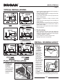
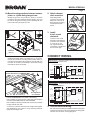
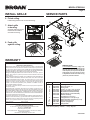
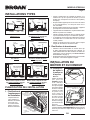
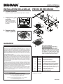
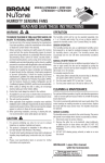
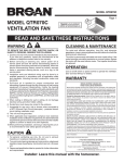
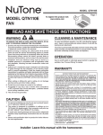
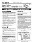
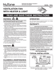
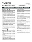
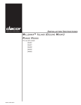
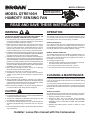
MODEL QTRE100H
Page 1
Register your product
online at www.broan.ca
MODEL QTRE100H
HUMIDITY SENSING FAN
BB0004
READ AND SAVE THESE INSTRUCTIONS
WARNING
OPERATION
TO REDUCE THE RISK OF FIRE, ELECTRIC SHOCK, OR
INJURY TO PERSONS, OBSERVE THE FOLLOWING:
The humidity control and fan can be operated separately. Use a
1- or 2-function wall control. Do not use a dimmer switch to operate
the humidity control. See “Connect Wiring” for details.
1. Use this unit only in the manner intended by the manufacturer.
If you have questions, contact the manufacturer at the address
or telephone number listed in the warranty.
2. Before servicing or cleaning unit, switch power off at service
panel and lock the service disconnecting means to prevent
power from being switched on accidentally. When the service
disconnecting means cannot be locked, securely fasten a
prominent warning device, such as a tag, to the service panel.
3. Installation work and electrical wiring must be done by qualified
personnel in accordance with all applicable codes and standards,
including fire-rated construction codes and standards.
4. Sufficient air is needed for proper combustion and exhausting of
gases through the flue (chimney) of fuel burning equipment to
prevent backdrafting. Follow the heating equipment manufacturer’s
guideline and safety standards such as those published by the
National Fire Protection Association (NFPA), and the American
Society for Heating, Refrigeration and Air Conditioning Engineers
(ASHRAE), and the local code authorities.
5. When cutting or drilling into wall or ceiling, do not damage
electrical wiring and other hidden utilities.
6. Ducted fans must always be vented to the outdoors.
7. Acceptable for use over a tub or shower when connected to
a GFCI (Ground Fault Circuit Interrupter) - protected branch
circuit.
8. This unit must be grounded.
9. When applicable local regulations comprise more restrictive
installation and/or certification requirements, the aforementioned
requirements prevail on those of this document and the installer
agrees to conform to these at his own expenses.
10.When performing installation, servicing or cleaning this unit, it
is recommended to wear safety glasses and gloves.
CAUTION
!
1. For general ventilating use only. Do not use to exhaust hazardous
or explosive materials and vapors.
2. This product is designed for installation in flat ceilings only. DO
NOT MOUNT THIS PRODUCT IN A WALL.
3. To avoid motor bearing damage and noisy and/or unbalanced
impellers, keep drywall spray, construction dust, etc. off power
unit.
4. Please read specification label on product for further information
and requirements.
SENSOR OPERATION
The humidity-sensing fan uses a sophisticated humidity sensor
that responds to: (a) rapid to moderate increases in humidity or
(b) humidity above a set-point. The humidity sensor may occasionally
turn the fan ON when environmental conditions change.
MANUAL ON WITH TIMED OFF
The humidity sensing fan has an additional operation feature. For
odor or vapor control, the fan can be energized by cycling the
power switch. Once the fan has been energized in this manner, it
will remain on for 20 minutes.
To manually energize the fan:
1. If fan power switch is already ON, proceed to Step 2; otherwise,
turn power switch ON for more than 1 second.
2. Turn fan power switch OFF for less than 1 second.
3. Turn fan power switch back ON and fan will turn ON.
CLEANING & MAINTENANCE
For quiet and efficient operation, long life, and attractive appearance
- lower or remove grille and vacuum interior of unit with the dusting
brush attachment.
The motor is permanently lubricated and never needs oiling. If the
motor bearings are making excessive or unusual noises, replace
the motor with the exact service motor. The impeller should also
be replaced.
SENSOR CLEANING
The humidity sensor is mounted in the control housing. The sensor
will operate most reliably when cleaned occasionally as follows:
1. Disconnect power at service entrance.
2. Remove the grille. Use a dry dustcloth, clean toothbrush,
or lightly vacuum to clean sensor and grille. DO NOT USE
ABRASIVE CLOTH, STEEL WOOL PADS, OR SCOURING
POWDERS.
3. DO NOT USE cleaning sprays, solvents, or water on or near
the sensor!
Installer: Leave this manual with the homeowner.
MODEL QTRE100H
Page 2
TYPICAL INSTALLATIONS
BH0001A
2A
Housing mounted to
I-joists.
Housing mounted
anywhere between
I-joists using hanger bars.
• Locate unit above (GFCI protected circuit required) or
within 5 feet of shower head.
• Locate unit away from heating or cooling sources which
can affect humidity levels.
• Do not locate near window. Unit may respond to the
outdoor humidity level.
• Unit must be installed in ceiling to properly sense
moisture.
• Locate unit only on flat ceilings up to 12 feet high for
proper sensing.
• The fan will operate most efficiently when located where
the shortest possible duct run and minimum number of
elbows will be needed.
• Use a roof cap or wall cap that has a built-in damper to
reduce backdrafts.
2. Plan the wiring.
• Plan to supply the unit with proper line voltage and
appropriate power cable. Power cable should be
routed to the switch box first and then to the unit (See
“CONNECT WIRING” on page 3).
• Do not operate this unit with a speed control.
Damage to the sensor unit will result.
A
Housing mounted
anywhere between
joists using hanger bars.
Housing mounted to joists.
INSTALL HOUSING & DUCT
1a. Mount
housing
to joist
or I-joist.
A
BH0006A
Housing mounted anywhere
between trusses
using hanger bars.
Housing mounted anywhere
between trusses
using hanger bars.
PLAN THE INSTALLATION
1. Choose the
installation
location.
INSULATION
(Can be placed
around and over
fan housing.)
ROOF
CAP *
The location of your
humidity sensing fan
is very important.
Use the following
guidelines for best
operation:
FAN
HOUSING
* Purchase
separately
Use pliers to
bend housing
TABS out to 90°.
Hold housing
in place so that
the housing
tabs contact the
bottom of the
joist. The housing
mounts with four
screws or nails.
Screw or nail
housing to joist
through lowest
holes in each
mounting flange,
then through
highest holes.
TABS
BD0001
SPACER
(use for mounting to I-Joist)
I-Joist
NOTE: Mounting
to I-JOIST
(shown) requires use of SPACERS (included) between
the highest hole of each mounting flange and the I-joist.
4-IN.
ROUND
DUCT *
4-IN. ROUND
ELBOW(S) *
WALL
CAP *
OR
MODEL QTRE100H
Page 3
1b. Mount housing anywhere between trusses,
joists, or I-joists using hanger bars.
2. Attach damper/
duct connector.
Sliding hanger bars are provided to allow for accurate
positioning of housing anywhere between framing. They can
be used on all types of framing (I-joist, standard joist, and
truss construction) and span up to 24”.
Snap damper/duct
connector onto housing.
Make sure connector is
flush with top of housing
and damper flap falls
closed.
TAB
SCREWS (4)
3. Install
4-inch round
ductwork.
ST
D
Connect 4-inch round
ductwork to damper/duct
connector. Run ductwork
to a roof cap or wall
cap. Tape all ductwork
connections to make them
secure and air tight.
MOUNTING
CHANNEL (2)
HANGER
BAR (4)
BD0002
Attach the MOUNTING CHANNELS to the housing using the
SCREWS supplied. Make sure TABS face “up” as shown.
Use the set of channel mounting holes (marked “STD”) to
mount the housing flush with the bottom of the drywall. Use
the other set of holes (not marked) to mount the housing
flush with the top of the drywall.
CONNECT WIRING
WIRING OPTION No. 1 - Allows fan to operate in automatic mode or manual mode
(for odor control) by cycling ON/OFF switch.
ON / OFF SWITCH
(PURCHASE SEPARATELY)
ORG
HOLE FOR OPTIONAL
SCREW MOUNTING (4)
ON / OFF
SWITCH
*SCREW (2)
BLK
BRN
BLK
120
VAC
LINE
IN
WHT
WHT
GRD
GRD
BLK
HUMIDITY
CONTROL
WHT
WHT
WHT
SWITCH BOX
BE0011A
FAN
UNIT
WIRING OPTION No. 2 - Fan can be turned ON, OFF, or set to operate automatically.
MODEL 68W, 2-FUNCTION CONTROL
(PURCHASE SEPARATELY)
RED
FAN
(ON/OFF)
ORG
COM
NAIL (4)
BOTTOM EDGE
OF FRAMING
Extend HANGER BARS to the width of the framing.
Hold ventilator in place with the hanger bar tabs wrapping
around the BOTTOM EDGE OF THE FRAMING.
NAIL ventilator to framing or fasten with screws (not provided)
through HOLES near nails.
*To ensure a noise-free mount: Secure hanger bars together
with SCREWS or use a pliers to crimp mounting channels
tightly around hanger bars.
HUMIDITY
CONTROL
(AUTO/OFF)
120
VAC
LINE
IN
BLK
HUMIDITY
CONTROL
BLK
FAN
WHT
WHT
BRN
BLK
WHT
WHT
GRD
GRD
SWITCH BOX
WHT
UNIT
4. Connect electrical wiring.
Run 120 VAC house wiring to installation location. Use proper
UL approved connector to secure house wiring to wiring plate.
Connect wires as shown in wiring diagrams.
MODEL QTRE100H
Page 4
INSTALL GRILLE
SERVICE PARTS
6. Finish ceiling.
Install ceiling material. Cut out around housing.
7. Attach grille
to housing.
Squeeze grille springs and
insert them into slots on
each side of housing.
8. Push grille
against ceiling.
WARRANTY
BROAN-NUTONE CANADA INC.
THREE-YEAR LIMITED WARRANTY
Broan-NuTone Canada warrants to the original consumer purchaser of its products that
such products will be free from defects in materials or workmanship for a period of three
(3) years from the date of original purchase. THERE ARE NO OTHER WARRANTIES,
EXPRESS OR IMPLIED, INCLUDING, BUT NOT LIMITED TO, IMPLIED WARRANTIES
OF MERCHANTABILITY OR FITNESS FOR A PARTICULAR PURPOSE.
During this three-year period, Broan-NuTone Canada will, at its option, repair or
replace, without charge, any product or part which is found to be defective under normal
use and service.
THIS WARRANTY DOES NOT EXTEND TO FLUORESCENT LAMP STARTERS OR
TUBES, BULBS OR BATTERIES, FILTERS, DUST, ROOF CAPS, WALL CAPS AND
OTHER ACCESSORIES FOR DUCTING. This warranty does not cover (a) normal
maintenance and service or (b) any products or parts which have been subject to misuse,
negligence, accident, improper maintenance or repair (other than by Broan-NuTone
Canada or an authorized representative), faulty installation or installation contrary to
recommended installation instructions.
The duration of an implied warranty is limited to the three-year period as specified for
the express warranty.
BROAN-NUTONE CANADA’S OBLIGATION TO REPAIR OR REPLACE, AT
BROAN-NUTONE CANADA’S OPTION, SHALL BE THE PURCHASER’S SOLE AND
EXCLUSIVE REMEDY UNDER THIS WARRANTY. BROAN-NUTONE CANADA SHALL
NOT BE LIABLE FOR INCIDENTAL, CONSEQUENTIAL OR SPECIAL DAMAGES
ARISING OUT OF OR IN CONNECTION WITH PRODUCT USE OR PERFORMANCE.
This warranty supersedes all prior warranties.
To qualify for warranty service, you must (a) notify Broan-NuTone Canada at the address or
telephone number stated below, (b) give the model number and part identification and (c)
describe the nature of any defect in the product or part. At the time of requesting warranty
service, you must present evidence of the original purchase date.
Date of Installation
Builder or Installer
Model Number and Product Description
IF YOU NEED ASSISTANCE OR SERVICE
For the location of your nearest Broan-NuTone Canada Inc. dealer:
Dial Toll Free: 1-888-882-7626
Please be prepared to provide:
Product model number • Date and proof of purchase • The nature of the difficulty
Broan-NuTone Canada Inc.
1140 Tristar Drive, Mississauga, Ontario L5T 1H9
SERVICE NOTE
To remove Blower Assembly: Unplug motor.
Remove screw (4) from motor plate flange. Find
the single TAB on the motor plate (located next
to the receptacle). Push up near motor plate tab
while pushing out on side of housing. Or insert
a straight-blade screwdriver into slot in housing
(next to tab) and twist screwdriver.
Key No.
Part No.
1
2
3
4
5
6
7
*
97016466
97016449
98010102
99170245
97017085
97017999
97017478
97017998
8
9
10
11
12
30260045
97017420
99140199
99111293
97016909
Description
Housing
Duct Connector - 4”
Wiring Plate
Screw, no. 8-18 x .375” (2 req’d)
Wire Panel/Harness Assembly
Motor/Blower Wheel Assembly
Motor Plate & Control Assembly
Blower Assembly
(includes key nos 6 & 7)
Flanged Nut no. 8-32 (4 req’d)
Grille Assembly (includes key no. 8)
Grille Spring (2 req’d)
Spacer (2 supplied)
Hanger Bars
Order service parts by “Part No.” - not by “Key No.”
30042338C
MODÈLE QTRE100H
Enregistrez votre produit
en ligne à www.broan.ca
VENTILATEUR
À DÉTECTION D’HUMIDITÉ
MODÈLE QTRE100H
LIRE ET CONSERVER CES DIRECTIVES
Page 5
BB0004
AVERTISSEMENT
FONCTIONNEMENT
AFIN DE RÉDUIRE LES RISQUES D’INCENDIE,
D’ÉLECTROCUTION OU DE BLESSURES CORPORELLES,
OBSERVEZ LES DIRECTIVES SUIVANTES :
1. N’utilisez cet appareil que de la façon prévue par le manufacturier. Si
vous avez des questions, contactez le manufacturier à l’adresse
ou au numéro de téléphone indiqué dans la garantie.
2. Avant de nettoyer ou de réparer l’appareil, coupez le courant au
panneau d’alimentation et verrouillez-en l’accès afin d’éviter sa
remise en marche accidentelle. Si le panneau d’alimentation ne
peut être verrouillé, apposez un avertissement bien en évidence,
par exemple une étiquette de couleur vive.
3. Les travaux d’installation et de raccordement électrique doivent
être effectués par du personnel qualifié en respectant les
normes et règlements en vigueur, y compris les normes et
codes de bâtiment en matière de prévention d’incendie.
4. Une circulation d’air efficace est requise afin d’assurer la
combustion et l’évacuation complète des gaz par la cheminée des
équipements à combustion pour prévenir les retours de cheminée.
Conformez-vous aux instructions et aux standards de sécurité des
manufacturiers d’équipement de chauffage, tels qu’ils sont publiés
par la National Fire Protection Association (NFPA) et l’American
Society for Heating, Refrigeration and Air Conditioning Engineers
(ASHRAE) ainsi que les responsables des codes locaux.
5. Lorsque vous coupez ou perforez un mur ou un plafond, prenez
garde de ne pas endommager les fils électriques ou autre
installation qui pourraient y être dissimulés.
6. Les ventilateurs avec conduits doivent toujours évacuer l’air à l’extérieur.
7. Pour installation au-dessus d’une douche ou d’une baignoire
lorsqu’il est raccordé à un circuit protégé par un disjoncteur de
fuite à la terre (DDFT).
8. Cet appareil doit être mis à la terre.
9. Lorsqu’une réglementation est en vigueur localement et
comporte des exigences d’installation et/ou de certification
plus restrictives, lesdites exigences prévalent sur celles de ce
document et l’installateur entend s’y conformer à ses frais.
10.Il est recommandé de porter des lunettes et des gants de sécurité lors
de l’installation, de l’entretien ou de la réparation de cet appareil.
Le contrôle du niveau d’humidité et la ventilation peuvent
fonctionner séparément. Utiliser une commande murale à 1 ou à
2 fonctions. Ne pas utiliser de gradateur pour contrôler le niveau
d’humidité. Voir « Branchement électrique » pour plus de détails.
ATTENTION !
1. Pour ventilation générale seulement. Ne l’utilisez pas pour
évacuer des vapeurs ou des matières dangereuses ou explosives.
2. Ce produit a été conçu pour l’installation dans les plafonds plats
seulement. NE PAS INSTALLER CE PRODUIT DANS UN MUR.
3. Afin d’éviter tout dommage au roulement du moteur et de débalancer
ou de rendre bruyante la roue du moteur, gardez l’appareil à l’abri
des poussières de gypse ou de construction/rénovation, etc.
4. Nous vous recommandons de lire l’étiquette indiquant les
caractéristiques de votre ventilateur pour de plus amples
renseignements et exigences.
FONCTIONNEMENT DU CAPTEUR
Le ventilateur à détection d’humidité utilise un capteur d’humidité
avancé qui actionne le ventilateur lorsque l’une de ces conditions
est détectée : (a) une augmentation du taux d’humidité de rapide
à modérée ou (b) un taux d’humidité supérieur au point de
préréglage. Le capteur peut à l’occasion activer le ventilateur lors
d’un changement de conditions ambiantes.
MODE MANUEL ACTIVÉ AVEC ARRÊT DIFFÉRÉ
Le ventilateur à détection d’humidité présente une caractéristique
opérationnelle de plus. Pour le contrôle des odeurs ou des vapeurs, le
ventilateur peut être activé en réglant de façon cyclique la commande
d’alimentation. Une fois que le ventilateur a été activé de cette
manière, il restera en marche pour une période de 20 minutes.
Pour activer manuellement le ventilateur :
1. Si la commande d’alimentation du ventilateur est déjà ACTIVÉE,
procéder à l’étape 2. Sinon, ACTIVER la commande pour plus
d’une seconde.
2. FERMER la commande d’alimentation du ventilateur pendant
moins d’une seconde.
3. Remettre en MARCHE la commande d’alimentation du
ventilateur; le ventilateur se mettra en MARCHE.
NETTOYAGE ET ENTRETIEN
Pour préserver un fonctionnement optimal et silencieux, une
longue durée de vie ainsi qu’une belle apparence, abaisser ou
retirer la grille et passer l’aspirateur à l’intérieur de l’appareil à
l’aide de la brosse à épousseter.
Le moteur est lubrifié à vie. Ne pas huiler. Si les roulements du
moteur sont plus bruyants qu’à l’habitude, remplacer le moteur
par le même moteur de rechange. La roue du ventilateur doit
également être remplacée.
NETTOYAGE DU CAPTEUR
Le capteur d’humidité est installé dans le boîtier de la commande.
Pour un fonctionnement optimal du capteur, le nettoyer à l’occasion
de la façon suivante :
1. Débrancher l’alimentation électrique du ventilateur.
2. Retirer la grille. Pour nettoyer la grille et le capteur : utiliser un
chiffon sec, une brosse à dents propre ou passer légèrement
l’aspirateur. NE PAS UTILISER UN CHIFFON ABRASIF, DE
LA LAINE D’ACIER OU UNE POUDRE À RÉCURER.
3. NE PAS UTILISER de vaporisateurs nettoyants, de solvants
ou de l’eau sur ou près du capteur!
Installateur : laisser ce manuel au propriétaire.
MODÈLE QTRE100H
Page 6
INSTALLATIONS TYPES
ENTRETROISE
POUR SOLIVE EN «
I»
CÂBLE
ÉLECTRIQUE
BRIDES
DE MONTAGE
BARRES DE SUSPENSION
(s’étirent jusqu’à 24 po)
BOÎTIER
CÂBLE
ÉLECTRIQUE
BOÎTIER
MATÉRIAU
DE PLAFOND
SOLIVE
EN « I »
GRILLE
Boîtier monté sur des
solives en « I ».
MATÉRIAU
DE PLAFOND
SOLIVE
EN « I »
GRILLE
Boîtier monté n’importe où entre
des solives en « I » utilisant des
barres de suspension.
CÂBLE
ÉLECTRIQUE
CÂBLE
ÉLECTRIQUE
BRIDES
DE MONTAGE
BARRES DE SUSPENSION
(s’étirent jusqu’à 24 po)
BOÎTIER
2. Planification du branchement.
BOÎTIER
BH0003F
MATÉRIAU
DE PLAFOND
SOLIVE
DE PLAFOND
GRILLE
MATÉRIAU
DE PLAFOND
CÂBLE
ÉLECTRIQUE
CÂBLE
ÉLECTRIQUE
BARRES DE SUSPENSION
(s’étirent jusqu’à 24 po)
BARRES DE SUSPENSION
(s’étirent jusqu’à 24 po)
BOÎTIER
BOÎTIER
GRILLE
SOLIVE
DE PLAFOND
Boîtier monté n’importe où entre
des solives utilisant des barres
de suspension.
Boîtier monté sur
des solives.
MATÉRIAU
DE PLAFOND
GRILLE
POUTRE
TRIANGULÉE
Boîtier monté n’importe où entre
des poutres triangulées utilisant
des barres de suspension.
MATÉRIAU
DE PLAFOND
GRILLE
POUTRE
TRIANGULÉE
Boîtier monté n’importe où entre
des poutres triangulées utilisant
des barres de suspension.
PLANIFICATION DE L’INSTALLATION
1. Planification de
l’emplacement
de l’installation.
L’emplacement de
votre ventilateur à
détection d’humidité
est crucial. Pour
un fonctionnement
optimal, suivre les
directives suivantes :
ISOLANT
(Peut être placé autour
et par-dessus le boîtier
du ventilateur.)
BOÎTIER DU
VENTILATEUR
CONDUIT ROND
DE 4 po*
COUDE(S) ROND(S)
* Vendus
DE 4 po*
séparément
BH0043F
• Choisir l’emplacement de l’appareil au-dessus ou à
l’intérieur de 5 pi de la pomme de douche (un circuit
protégé par un disjoncteur de fuite à la terre (DDFT)
est requis).
• Ne pas installer l’appareil près d’une source de chaleur
ou de refroidissement, car cela peut influer sur le
taux d’humidité.
• Ne pas installer l’appareil près d’une fenêtre. L’appareil
peut répondre au taux d’humidité extérieur.
• L’appareil doit être installé dans un plafond afin de bien
détecter la présence d’humidité.
• Installer l’appareil seulement dans un plafond plat de
12 pi de haut maximum pour une détection optimale.
• Le ventilateur fonctionnera plus efficacement lorsqu’il
est installé avec un conduit très court et le moins de
coudes possible.
• Utiliser un capuchon de toit ou de mur ayant un clapet
intégré afin de réduire le refoulement d’air.
CAPUCHON
DE TOIT *
CAPUCHON
MURAL*
• Planifier la bonne alimentation en tension ainsi que
le câble d’alimentation approprié pour l’appareil. Le
câble d’alimentation doit être acheminé au boîtier de
l’interrupteur, puis à l’appareil (voir BRANCHEMENT
ÉLECTRIQUE à la page 7).
• Ne pas faire fonctionner cet appareil avec une commande
de vitesse. Cela endommagerait le capteur.
INSTALLATION DU
BOÎTIER ET DU CONDUIT
1a. Installation
du boîtier à
la solive ou
à la solive
en « I ».
Utiliser des pinces
PATTES
pour plier les
PATTES du boîtier
à 90°. Maintenir
le boîtier en place
afin que ses pattes
ENTRETOISE
touchent au bas de
(utiliser pour installer à la
solive en « I »)
la solive. Le boîtier
s’installe à l’aide
de quatre vis ou
clous. Visser ou
clouer le boîtier à
la solive à travers
les trous les plus
bas dans chaque
bride de montage,
puis dans les trous
SOLIVE en « I »
plus haut.
NOTE : l’installation à la SOLIVE EN I (illustrée ci-dessus)
requiert l’utilisation D’ENTRETOISES (incluses) entre les
trous les plus hauts de chaque bride de montage et la
solive en I.
BD0001
OU
MODÈLE QTRE100H
Page 7
1b. Installation du boîtier n’importe où entre des
poutres triangulées, des solives, des solives
en I en utilisant des barres de suspension.
Des barres de suspension à glissière sont fournies pour
permettre un positionnement du boîtier n’importe où entre les
éléments d’armature. Elles peuvent être utilisées sur
n’importe quel type d’armature (solive en I, solive standard et
poutre triangulée de construction) et peuvent s’étirer jusqu’à 24 po.
VIS (4)
Installer le clapet/raccord
de conduit sur le boîtier.
S’assurer qu’il est à ras
avec le dessus du boîtier
et que le clapet se
ferme parfaitement.
PATTE
3. Installation
d’un conduit rond
de 4 po.
ST
D
GLISSIÈRE (2)
BARRE DE
SUSPENSION (4)
2. Fixation du
clapet/raccord
de conduit.
Fixer un conduit rond de
4 po au clapet/raccord
de conduit. Acheminer
le conduit au capuchon
de toit ou de mur. Sceller
hermétiquement tous les
joints à l’aide de ruban
à conduits.
BRANCHEMENT ÉLECTRIQUE
BD0002
Fixer les GLISSIÈRES au boîtier en utilisant les VIS fournies.
S’assurer que les PATTES soient vers le haut tel qu’il est
illustré. Utiliser l’ensemble des trous de montage (marqués
STD) pour fixer le boîtier à ras avec le matériau du plafond.
Utiliser l’autre ensemble de trous pour fixer le boîtier à ras
avec le dessus du matériau de plafond.
Option de branchement n° 1 : permet au ventilateur de fonctionner en mode
automatique ou en mode manuel (pour le contrôle des odeurs) en réglant de façon
cyclique l’interrupteur MARCHE/ARRÊT.
INTERRUPTEUR MARCHE/ARRÊT
(VENDU SÉPARÉMENT)
ORANGE
NOIR
INTERRUPTEUR
MARCHE/ARRÊT
*VIS (2)
TROU POUR VIS
DE MONTAGE
OPTIONNELLE (4)
NOIR
BRUN
NOIR
ENTRÉE
BLANC
DE
120 V c.a. MISE À
LA TERRE
CAPTEUR
D’HUMIDITÉ
VENT.
BLANC
BLANC
BLANC
MISE À
LA TERRE
BLANC
APPAREIL
BOÎTIER
D’INTERRUPTEUR
Option de branchement n° 2 : le ventilateur peut être mis EN MARCHE, ARRÊTÉ
ou réglé pour fonctionner automatiquement.
MODÈLE 68 W, COMMANDE À 2 FONCTIONS
(VENDUE SÉPARÉMENT)
ROUGE
VENTILATEUR
(MARCHE/ARRÊT)
ORANGE
COM
CLOU (4)
REBORD INFÉRIEUR
DE L’ARMATURE
Étirer les BARRES DE SUSPENSION à la largeur entre
deux poutres.
Maintenir le ventilateur en place à l’aide des pattes des
barres de suspension appuyées sur le REBORD INFÉRIEUR
DE L’ARMATURE.
CLOUER le ventilateur à l’armature ou le visser (vis non
fournies) dans les TROUS près des clous.
*Pour un fonctionnement silencieux : fixer les barres de
suspension ensemble à l’aide de VIS ou utiliser des pinces pour
bien serrer les glissières autour des barres de suspension.
COMMANDE
D’HUMIDITÉ
(AUTO/ARRÊT)
NOIR
ENTRÉE
BLANC
DE
120 V c.a. MISE À LA TERRE
NOIR
CAPTEUR
D’HUMIDITÉ
NOIR
VENT.
BLANC
BLANC
BRUN
BLANC
BLANC
MISE À LA TERRE
BOÎTIER DE L’INTERRUPTEUR
APPAREIL
4. Branchement des fils électriques.
Acheminer un fil de 120 V c.a. jusqu’à l’emplacement de
l’installation. Utiliser un connecteur approprié et homologué
UL pour fixer le fil d’alimentation à la plaque de branchement.
Brancher les fils tel qu’il est illustré dans les schémas ci-dessus.
MODÈLE QTRE100H
Page 8
INSTALLATION DE LA GRILLE
PIÈCES DE RECHANGE
6. Finition du plafond.
Installer le matériau du plafond. Découper autour du boîtier.
7. Fixation de la grille
au boîtier.
Serrer les ressorts de la
grille et les insérer dans
les fentes de chaque côté
du boîtier.
8. Pousser la grille
contre le plafond.
PATTE
GARANTIE
NOTE POUR SERVICE
Pour retirer le bloc ventilateur : Débrancher le
moteur. Retirer la vis (4) de la plaque du moteur.
Repérer l’unique PATTE sur la plaque moteur
(située à côté de la prise). Pousser vers le haut près
de la patte de la plaque du moteur, tout en poussant
vers l’extérieur sur le côté du boîtier, ou insérer
un tournevis à lame plate dans la fente du boîtier
(à côté de la patte) et faire tourner le tournevis.
BROAN-NUTONE CANADA INC.
GARANTIE LIMITÉE DE TROIS ANS
Broan-NuTone Canada garantit à l’acheteur consommateur original de ses produits qu’ils
sont exempts de défauts dans les matières premières ou la main-d’œuvre pour une période de
trois (3) ans à compter de la date d’achat originale. IL N’Y A PAS D’AUTRES GARANTIES,
EXPRIMÉES OU IMPLICITES, Y COMPRIS, MAIS SANS SE LIMITER AUX GARANTIES IMPLICITES
POUR FIN DE COMMERCIALISATION ET DE CONVENANCE DANS UN BUT PARTICULIER.
Pendant cette période de trois ans, Broan-NuTone Canada, à son choix, réparera ou
remplacera gratuitement tout produit ou pièce qui s’avère défectueux dans des conditions
normales d’utilisation et d’entretien.
CETTE GARANTIE NE COUVRE PAS LES STARTERS DE LAMPES FLUORESCENTES OU
LES TUBES, LES AMPOULES OU LES PILES, LES FILTRES, LE CONDUIT, LES CAPUCHONS
DE TOITURE, LES CAPUCHONS MURAUX ET LES AUTRES ACCESSOIRES DE CONDUIT.
Cette garantie ne couvre pas (a) l’entretien et le service normal ou (b) tout produit ou pièce
endommagés à la suite d’un mauvais usage, de négligence, d’un accident, d’un entretien inapproprié
ou d’une réparation (autre qu’effectuée par Broan-NuTone Canada ou un représentant autorisé),
d’une mauvaise installation ou d’une installation contraire au mode d’installation recommandé.
La durée de toute garantie implicite est limitée à une période de trois ans tel qu’il est spécifié
pour la garantie exprimée.
L’ENGAGEMENT DE BROAN-NUTONE CANADA DE RÉPARER OU DE REMPLACER AU
CHOIX DE BROAN-NUTONE CANADA, DOIT ÊTRE LA SEULE OBLIGATION EXCLUSIVE
EN VERTU DE CETTE GARANTIE. BROAN-NUTONE CANADA NE DOIT PAS ÊTRE TENUE
RESPONSABLE DES DOMMAGES DIRECTS, INDIRECTS OU SPÉCIAUX SURVENANT À
CAUSE DE L’UTILISATION OU LA PERFORMANCE DE SES PRODUITS OU EN RAPPORT
AVEC CELLES-CI. Cette garantie annule toutes les garanties précédentes.
Pour obtenir le service après-vente aux fins de la garantie, vous devez (a) aviser Broan-NuTone
Canada à l’adresse ou au numéro de téléphone ci-dessous, (b) donner le numéro du modèle
et l’identification de la pièce et (c) décrire la nature de tout défaut du produit ou de la pièce.
Lorsque vous demanderez le service après-vente aux fins de la garantie, vous devez présenter
une preuve de la date d’achat originale.
Date d’installation
N° repère N° pièce
1
2
3
4
5
6
7
*
8
9
10
11
12
97016466
97016449
98010102
99170245
97017085
97017999
97017478
97017998
30260045
97017420
99140199
99111293
97016909
Description
Boîtier
Raccord de conduit de 4 PO
Plaque de branchement
Vis n° 8-18 x 0,375 PO (2 requises)
Panneau de branchement/harnais
Assemblage moteur et roue de ventilateur
Ensemble plaque moteur et commande
Bloc ventilateur (inclut les repères 6 et 7)
Écrou hexagonal à collet n° 8-32 (4 requis)
Ensemble grille (inclut le repère n° 8)
Ressort de la grille (2 requis)
Entretoise (2 fournies)
Barres de suspension
Entrepreneur ou installateur
N° du modèle et description du produit
POUR OBTENIR DE L’ASSISTANCE OU DU SERVICE
Pour connaître le centre de service Broan-NuTone Canada Inc. autorisé le plus proche :
Composez le numéro sans frais : 1 888 882-7626
Gardez à portée de la main :
Le numéro du modèle • la date et la preuve d’achat • le type de problème
Broan-NuTone Canada Inc.
1140 Tristar Drive, Mississauga, Ontario L5T 1H9
Commander les pièces de rechange par n° de pièce
et NON par n° de repère.
30042338C