1
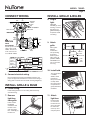
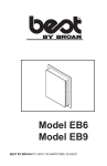
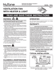
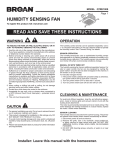
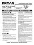
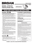
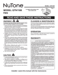
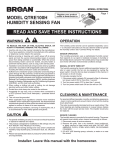
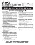
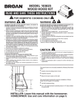
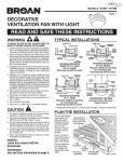
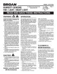
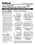
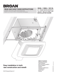
REGISTER YOUR PRODUCT ONLINE AT
www.nutone.com/register
MODEL 765HFL
Page VENTILATION FAN
WITH HEATER & FLUORESCENT LIGHT
READ AND SAVE THESE INSTRUCTIONS
WARNING
OPERATION
TO REDUCE THE RISK OF FIRE, ELECTRIC SHOCK, OR INJURY TO PERSONS, OBSERVE THE FOLLOWING:
1. Use this unit only in the manner intended by the manufacturer.
If you have questions, contact the manufacturer at the address
or telephone number listed in the warranty.
2. Before servicing or cleaning unit, switch power off at service
panel. Lock or tag service panel to prevent power from being
switched on accidentally.
3. Installation work and electrical wiring (including switch location)
must be done by a qualified person(s) in accordance with all
applicable codes and standards.
4. Provide sufficient air for proper combustion and exhausting of
gases through the flue (chimney) of fuel burning equipment
to prevent backdrafting. Follow the combustion equipment
standards such as those published by the National Fire Protection Association (NFPA), the American Society for Heating,
Refrigeration and Air Conditioning Engineers (ASHRAE), and
local codes.
5. When cutting or drilling into wall or ceiling, do not damage
electrical wiring and other hidden utilities.
6. Ducted fans must always be vented to the outdoors.
7. Provide a separate 20 AMP circuit. Use 12 GA., 90o C minimum
power cable which meets code.
8. Do not use a speed control with this product.
9. This unit must be grounded.
Use a 3-Function Control to operate the heater, fan, and light
separately. See “Connect Wiring” for details.
CAUTION
1. For general ventilating use only. Do not use to exhaust hazardous or explosive materials and vapors.
2. This product must be mounted in a flat ceiling only. Installations in ceilings 9-feet high or less will provide
maximum comfort. DO NOT MOUNT THIS PRODUCT IN A
WALL.
3. Install in ceiling only - at least 6 inches from any wall.
4. To avoid motor bearing damage and noisy, unbalanced impellers, keep drywall spray, construction dust, etc. off motor and
impeller.
5. Read specification label on product for information and requirements.
WARRANTY
BROAN-NUTONE ONE YEAR LIMITED WARRANTY
Broan-NuTone warrants to the original consumer purchaser of its products that such products
will be free from defects in materials or workmanship for a period of one year from the date
of original purchase. THERE ARE NO OTHER WARRANTIES, EXPRESS OR IMPLIED,
INCLUDING, BUT NOT LIMITED TO, IMPLIED WARRANTIES OF MERCHANTABILITY
OR FITNESS FOR A PARTICULAR PURPOSE.
During this one-year period, Broan-NuTone will, at its option, repair or replace, without
charge, any product or part which is found to be defective under normal use and service.
THIS WARRANTY DOES NOT EXTEND TO FLUORESCENT LAMP STARTERS AND
TUBES. This warranty does not cover (a) normal maintenance and service or (b) any
products or parts which have been subject to misuse, negligence, accident, improper
maintenance or repair (other than by Broan-NuTone), faulty installation or installation
contrary to recommended installation instructions.
The duration of an implied warranty is limited to the one-year period as specified for the
express warranty. Some states do not allow limitation on how long an implied warranty
lasts, so the above limitation may not apply to you.
BROAN-NUTONE’S OBLIGATION TO REPAIR OR REPLACE, AT BROAN-NUTONE’S
OPTION, SHALL BE THE PURCHASER’S SOLE AND EXCLUSIVE REMEDY UNDER
THIS WARRANTY. BROAN-NUTONE SHALL NOT BE LIABLE FOR INCIDENTAL, CONSEQUENTIAL OR SPECIAL DAMAGES ARISING OUT OF OR IN CONNECTION WITH
PRODUCT USE OR PERFORMANCE. Some states do not allow the exclusion or limitation
of incidental or consequential damages, so the above limitation may not apply to you.
This warranty gives you specific legal rights, and you may also have other rights, which
vary from state to state. This warranty supersedes all prior warranties.
To qualify for warranty service, you must (a) notify Broan-NuTone at the address or telephone
number stated below, (b) give the model number and part identification and (c) describe
the nature of any defect in the product or part. At the time of requesting warranty service,
you must present evidence of the original purchase date.
Broan-NuTone LLC Hartford, Wisconsin www.nutone.com 888-336-3948
Installer: Leave this manual with
the homeowner.
TYPICAL INSTALLATION
CEILING
JOIST, TRUSS,
OR I-JOISTS
CLEANING & MAINTENANCE
For quiet and efficient operation, long life, and attractive appearance - lower or remove grille and vacuum interior of fan with a
dusting brush attachment.
The motor is permanently lubricated and never needs oiling. If
the motor bearings make excessive or unusual noise, replace
the motor with the exact service motor. The impeller should also
be replaced.
Replace light bulb with a 27-Watt, 3500K (maximum) GU24
fluorescent lamp.
POWER
CABLES
MOUNTING
CHANNELS
HOUSING
CEILING
MATERIAL
GRILLE
Housing mounted to joists, trusses, or I-joists.
Up to 24-inches on-center.
MODEL 765HFL
Page PLAN THE INSTALLATION
insulation
(Can be placed
around and over
housing.)
hole for optional screw mounting (4)
* screw (2)
ROOF
CAP *
nail (4)
bottom edge of framing
2. Mount housing.
housing
* Purchase
4-in.
ROUND
DUCT *
separately
4-in. ROUND
ELBOW(S) *
Extend hanger bars to the width of the framing. Hold fan
in place with the hanger bar tabs wrapping around the
bottom edge of the framing.
Nail fan to framing or fasten with screws (not provided)
through holes near nails.
* To ensure a noise-free mount: Secure hanger bars
together with screws or use a pliers to crimp mounting
channels tightly around hanger bars.
WALL
CAP *
The unit will operate most quietly and efficiently when located
where the shortest possible duct run and minimum number of
elbows will be needed.
Use a roof cap or wall cap that has a built-in damper to reduce
backdrafts.
Plan to supply the unit with proper line voltage and appropriate
power cable.
3. Attach
damper
/ duct
connector to
housing.
INSTALLATION
tab
hanger
bars
channel
channel
hanger
bars
1. Insert hanger bars.
Four (4) sliding hanger bars are provided to allow for
accurate positioning of housing anywhere between
framing. They can be used on all types of framing (I-joist,
standard joist, and truss construction) and span up to 24”.
Slide hanger bars into channels on housing. Make sure
hanger bar tabs face “up” as shown.
Snap damper /
duct connector
onto housing.
Make sure
connector is flush
with top of housing
and damper flap
falls closed.
4. Install 4inch round
ductwork.
Connect 4-inch
round ductwork
to damper / duct
connector. Run
ductwork to a roof
cap or wall cap.
Tape all ductwork
connections to
make them secure
and air tight.
MODEL 765HFL
Page CONNECT WIRING
INSTALL GRILLE & BULBS
LIGHT
&
FAN
HEAT
BLACK to RED
(Heat)
8. Plug-in
light.
VENTILATOR
HOUSING
RED to BLUE
(Light)
BLACK to BLACK
(Fan)
WHITE to WHITE
WHITE to WHITE
WIRING PLATE
FROM VENTILATOR
GROUND
RED
WHITE
to
WHITE
K
RATING
SPECIFICATIONS
Each two-position rocker
switch is rated 15 A @
120VAC. The total load
on this control must not
exceed 20 A @ 120VAC.
FAN
N
GREE
HEAT
BLACK
BLACK
120 VAC LINE IN
RED
BLU
VENT
SWITCH
BLK
BLK
HEAT
SWITCH
BLK
BLK
RED
WHT
LIGHT
VENT
WHT
WHT
WHT
H E AT
WHT
GRD
UNIT
5. Connect electrical wiring.
10. Install bulb.
Run 120 VAC house wiring to installation location. Use
proper UL approved connectors to secure house wiring to
wiring plate. Connect wires as shown in wiring diagram(s).
INSTALL GRILLE & BULB
6. Finish ceiling.
The unit accepts
a 27-Watt,
3500K, GU24
fluorescent
lamp. Insert tabs
on lamp base
into slots in lamp
receptacle and
gently twist lamp
clockwise.
Install ceiling material. Cut out ceiling material closely
around housing.
7. Remove
light lens
from grille.
Place grille/
reflector
combination
over protruding
screw and
fasten in place
using acorn nut
provided. HAND
TIGHTEN acorn
nut 1/4 turn after
it is snug.
WHT
D O U B L E - G A N G S W I T C H B OX
9. Attach
grille.
LIGHT
SWITCH
GRD
LIGHT
BLAC
caution
LINE
IN
Hold grille
assembly up near
housing. Connect
light plug from
grille assembly to
receptacle inside
of housing.
Insert a small
flat-bladed
screwdriver into
the slot at one
end of the light
lens. Carefully pry
the lens out.
11. Attach
light lens.
Hook the tabs
on one end of
the lens into the
slot in the grille.
Lift other end
of lens up and
snap into place.
SCREW
grille
acorn nut
light
reflector
use
this
hole
bottom view
MODEL 765HFL
Page 12. Rotate
heater
grille.
5
6
Use a flat-bladed
screwdriver to
rotate the round
heater grille to
provide heat
in the desired
direction.
1
2
3
4
5
6
7
8
9
10
11
12
13
14
15
16
17
18
19
20
21
22
23
24
25
26
27
28
29
30
31
32
33
34
35
**
**
Part No.
97017572
97017712
97017711
97016449
98010407
99170245
99150471
97017713
99420666
99150415
97017609
98010405
99020294
99160304
99260428
99260488
98010409
97016565
99080606
99020293
98010089
99080602
99100491
97017606
93260454
99150583
93150459
99250959
99260558
97017663
97017672
97005316
99111414
99271360
97017739
97017768
97017769
2
1
7
35
9
3
SERVICE PARTS
Key No.
6
Description
Housing Assembly Slide Mounting Channel
RH (2 req) Slide Mounting Channel
LH (2 req) Duct Connector Assembly, 4” Electrical Knockout Panel Screw, #8-18 X .375” * (5 req) Screw, Ground #10-32 X .500
PH HWH * (2 req) Wire Panel Assembly Wire Clip Screw, 8B X .25
SL HX SR W * (4 req) Heater Scroll Transition Heater Wheel
Screw, #10-24 X .375” * (2 req) Nut, #6-32 X 5/16 * Twin Whiz
(4 req) Nut, #10-24 * Whiz Hex Flange (4 req) Heater Motor Bracket Heater Element Heater Motor Fan Wheel
Heating Element
Mounting Bracket Fan Motor Isolator Bushing (4 req) Partition Assembly Sheet Metal Nut, #8-18 *
(2 req) Screw, #10-24 X 1.25” * Screw, #8-18 X .500” * (2 req) Washer, Flat, #8 * (4 req) Nut, Hex Lock, #8-32 * (4 req) Grille Assembly Reflector Assembly
Acorn Nut Light Lens
Fluorescent Lamp, 27W, 3500K, GU24
Screw Hardware Bag
Heater Scroll Assembly
(Includes Key Nos. 6,
10 thru 19, 21)
Blower Assembly
(Includes Key Nos. 20, 22, 23, 24, 26, 28, 29)
3
8
6
21
4
13
15
10
17
16
19
2
18
10
11
6
12
14
26
20
22
25
23
24
27
28
29
30
Replacement parts
can be ordered on our
website. Please visit us
at www.nutone.com
34
Order service parts by “Part No.” - not by “Key No.”
* Standard hardware - may be purchased locally.
** Not shown assembled.
31
32
33
99044117B