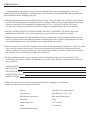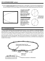
1
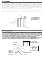
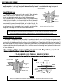
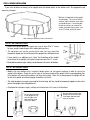
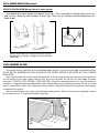
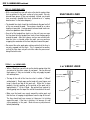
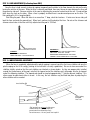
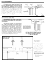
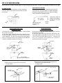
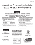
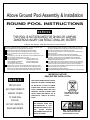
P /N 95-0443 04-07
Above Ground Pool Assembly & Installation
ROUND POOL INSTRUCTIONS
WA R N I N G :
THIS POOL IS NOT DESIGNED FOR DIVING OR JUMPING.
DANGEROUS INJURY CAN RESULT-SHALLOW WATER!!!
Follow All Safety and Maintenance Instructions
Your pool is designed for years of pleasurable, safe family fun. But, when used
incorrectly, a swimming pool can be dangerous. To insure your pool is used
safely you must observe the following safety precautions:
Do not dive!-Do not jump!- No rough play!- No running or pushing!
Do not walk on the top rail. It can be slippery and is not a walkway.
Be sure to install all safety labels provided with your pool according to the
instructions.
Keep a safety rope 1/4” by 50’ with a flotation buoy with an outside diameter of 15”.
Have accessible in a prominent area by your pool.
Post near all entrances to pool area; a list of telephone numbers of the:
• Nearest available police
• Nearest ambulance service
• Nearest available fire department
• Nearest available hospital
• Nearest available rescue unit
• Nearest available physician
• 911 emergency number if available
Provide fencing or enclosure which is independent of the house as a closure
around the entire pool area. The fencing must be made of durable material, a
minimum of 4’ in height from ground level and with closures with self-latching
locks, to make pool inaccessible to toddlers and uninvited guests. Make sure
gate is always closed. Be sure to follow local building code requirements for load
capacity and fencing if using an aftermarket or homebuilt deck. You must make
sure all fence and barriers are in working order so that pool is always protected.
Check with your local town for any special laws in your locale.
Never drink alcoholic beverages or use any intoxicants which could hinder your
judgment and reflexes.
Never use pool alone. All children must be supervised continuously.
Do not use pool if bottom is not clearly visible: At night, sufficient lighting must
be available. It is the pool owners sole responsibility to provide adequate
lighting for pool bottom, safety signs and walkways, which exceeds minimum
standards of the IES of North America.
Do not climb, stand or sit on any pool structure or the filter system. Components
such as the filtration system, pumps and heater must be positioned so as to
prevent their being used as a means of access to the pool by young children.
Be sure that all toys, chairs and tables or similar objects that a young child could
climb on be at least four feet (4’) from pool.
Do not use pool during electrical or rain storms.
See available National Spa and Pool Institute (NSPI), publications for more tips on pool safety.
IMPORTANT NOTICE!
READ BEFORE INSTALLATION
WA R N I N G :
ENCLOSED IN FRAME CARTON IS SAFETY
ENVELOPE. THE SAFETY STICKERS MUST
DO NOT AFFIX
BE INSTALLED AS PER FOLLOWING
ANY OTHER PRODUCTS
INSTALL WARNING LABELS WILL VOID
MADE BY OTHERS
TO YOUR POOL
SUCH AS,
BUT NOT LIMITED TO,
DECKS AND SLIDES!
INSTRUCTIONS. FAILURE TO PROPERLY
WARRANTY. FAILURE TO MOUNT THESE
SAFETY LABELS MAY SUBJECT YOU TO
SUBSTANTIAL LIABILITY IN CASE OF
SIGN MUST BE PLACED
ON WALL NEXT TO ENTRY
TO POOL
INJURY.
THESE WARNINGS ARE NOT TO
BE REMOVED UNDER ANY
CIRCUMSTANCES! IF THEY
BECOME DISCOLORED OR FALL
OFF,
PLEASE
REQUEST
REPLACEMENTS WHICH WILL BE
SENT AT NO CHARGE.
SIGN TO BE PLACED ON
LINER ABOVE WATER LINE
OPPOSITE ENTRY TO POOL
INTRODUCTION:
Congratulations on becoming the owner of a new Sharkline above ground swimming pool. This is the
instruction packet for installing your swimming pool. The following are some helpful hints that you should take
into consideration before installing your pool.
1) Read through the entire instruction booklet before you begin. This will enable you to find out exactly what is
involved with installing your swimming pool before you begin. While you are going through the instructions,
please be aware that all of the diagrams are representative of a 15' x 30' pool. If you have a dif ferent
size pool you will find that your pool has a dif ferent number of uprights than the ones in the diagrams.
2) DO NOT ATTEMPT INSTALLATION IN WINDY OR GUSTY WEATHER. This will not only make
installation more difficult, it may result in damage to your pool before it is completely installed.
3) Although we have broken down the installation into many simple steps, you will probably find that steps one
and two will be the most labor intensive and time consuming steps. Once you have completed those two steps
you should find that the rest of the installation moves along much more quickly .
4) Please be sure to review all safety material and local codes before beginning your installation. There is a yellow
safety envelope packed with your pool. This envelope contains safety material and warning stickers to be
placed on your pool. If you are missing any of these items please contact your dealer or the factory to obtain it.
The warranty is void if all safety precautions are not followed.
5) In the event that you need to make a warranty claim, it is important to know the size and model of your
swimming pool in order to expedite the handling of your claim. Please fill in the information below and keep
for your records.
NAME OF POOL:
SIZE OF POOL:
DATE OF PURCHASE:
NAME OF POOL WALL:
NAME OF LINER:
6) Make sure you have the necessary tools and materials before beginning your installation.
Below is a list of the tools and materials needed.
-Shovel
-Carpenters level and/or transit
-Tape measure
-Patio Blocks (2" x 8" x 16")
-Phillips head screwdriver
-Box cutter (Razor blade)
-Duct tape
-Tamp
-Sand or pool base
-5/16" wrench
-Filter
-1/4" wrench
-Skimmer/Return fitting
ROUND POOL INSTALLATION INSTRUCTIONS
ad
’R
11
18’ ROUND
POOL
20’ ROUND
POOL
21’ ROUND
POOL
s
’R
s
iu
ad
”
’6
ad
R
’R
ad
iu
s
iu
15
14
13
27’ ROUND
POOL
28’ ROUND
POOL
POOL
POOL
19
’R
R
”
’6
17
33’ ROUND
ad
iu
ad
iu
s
ad
’R
16
30’ ROUND
iu
s
s
24’ ROUND
POOL
.5
11
’R
15’ ROUND
POOL
10
8
R ’ 6”
ad
iu
s
12’ ROUND
POOL
s
7
R ’
ad
iu
ad
’R
ad
iu
s
iu
s
iu
s
POOL AREA DIMENSIONS (POOL RADIUS PLUS ONE FOOT)
36’ ROUND
POOL
Radius means the measurement from the center point of the pool to the pool wall.
STEP 1: POOL LOCATION
Do not locate pool over underground lines, septic tanks, under electrical lines, near hazardous structures, or out of local code
restrictions. It is essential that the area selected for your pool has a level and firm base. Do not assemble your pool on asphalt,
tar or oil base surfaces. Avoid areas with sharp objects, or ground treated with weed killer or other chemicals. Also avoid areas
where nut grass, Bermuda grass or bamboo grass grows, as they can grow through your liner. Grass must be removed. Do not
place components such as filters, pumps, and heaters in a way that they can be used as a means of access to pool by young
children. Be sure to follow all local building codes and obtain all building permits required for your area.
e
l
p
am
S
*BE SURE TO AVOID:
-All electrical wires
-All gas lines
-Septic tanks
-Cesspools
-Dry wells
-Tree roots/stumps
-buried debris(trees,
building material, etc.)
-sudden slopes within 6’
of pool area
STEP 2: TO PREPARE THE POOL SITE
Determine the pool circumference by putting a stake in the ground at the center of the location desired, and with a line equal
in length to the radius of the pool area (1/2 the pool size plus 12”), mark off the circumference with a sharp object, lawn edger,
white powder, or spray paint.
After all of the sod has been removed, you must make the pool area absolutely level as measured by a level or transit, not
simply by the naked eye. Find the lowest spot within the pool area and level the ground to that lowest spot. Do not add dirt to
the low areas as that will cause settling after the pool is filled with water. It is the high areas that must be dug away. The footing
(perimeter) of the pool must be a solid foundation to prevent the pool from settling into dirt that is loosened by rain and water
splashing over the side. Once again, clean the area of all sharp objects, including roots that later effect your swimming pool. For
leveling, we recommend that you use a long straight edge board and a carpenters level or transit.
LEVEL POOL AREA
(Pool Dia. + 12”)
Remove soil and
grass from high
areas to be
equal with the
low areas.
Remove grass only
from the low areas.
STEP 3: BOTTOM RING ASSEMBLY
A. Use your pool parts breakdown sheet to separate all pool components, becoming familiar with each part.
B. Take the curved bottom rails and place them in a circle along the circumference of the pool area. IMPORTANT: Make sure you
are using the bottom rails and not the inner stabilizer bars. The bottom rails on some pool models are made of resin and
not metal. The stabilizer bars are always metal and they have a male end and a female end. The bottom rails are the
larger width rails that have the straight cuts on both ends. The bottom rails do not interlock (see diagram.)
Please note the different bottom tracks.
Inner Stabilizer 5/8” x 5/8”.
Used on the top of the pool.
Resin Bottom Track
Bottom Rail 1” x 5/8”. Used on
the bottom of the pool.
Metal Bottom Track
C. Assemble the rails by using the bottom plates or bottom cuffs to join them together. IMPORTANT: Some pools have resin
bottom plates or resin bottom cuffs rather than the traditional metal bottom plate. Please refer to your pool parts
breakdown sheet to confirm which component applies to your pool. Rails should be inserted into the bottom plates or
cuffs up to, but not exceeding, the stops on the plate or cuff. Rail can be squeezed between thumb and forefinger to
facilitate insertion into the plates or cuffs.
Please note the different bottom tracks.
Resin Bottom Track
* Adjust rails in or out as necessary
to form a true circle.
The bottom rail is inserted up
to the dimple only.
Metal Bottom Track
The bottom rail is inserted up
to the dimple only.
STEP 3: BOTTOM RING ASSEMBLY continued
D. Check the roundness of your circle by measuring diameter across in several locations. Since the rails do not automatically form a
true circle, DO NOT SKIP THIS STEP! Otherwise, you might end up with a slightly oval shape, which can cause problems later on.
Once you have formed a true circle, stake the bottom rails at every other rail with a screwdriver, being careful not to scratch the rails.
FOR POOLS WITH ODD
NUMBER of BOTTOM
PLATES or CUFFS:
Measure from bottom
plate to center of opposite
bottom rail at every other
bottom plate. When true,
stake into position.
FOR POOLS WITH EVEN
NUMBER of BOTTOM
PLATES or CUFFS:
Measure from bottom
plate to opposite bottom
plate at every other
plate. When true, stake
into position.
Measurements
must go through
center of the pool.
STEP 4: PATIO BLOCK INSTALLATION
Once the frame is in position, begin centering bottom plates or cuffs on 2”x8”x16” patio blocks. Sink patio block into ground
under bottom plate or cuff, making sure that the block is level in all directions (side to side as well as front to back). Repeat this
step around the frame making the tops of all blocks level with the ground. Do not install blocks or rails on loose sifted soil or sand.
There must be no space between the ground and the bottom of the rails. All patio blocks must be flush with the ground, solid and
level with each other in all directions. You may remove a bottom rail at this time to cart in sand or sifted soil for the cove (step 9) as
long as your pool ring remains staked in position. Make sure you replace the bottom rail in its proper position. A chalk outline of
the bottom plates or cuffs on the patio block is an easy and temporary way to ensure that your track does not move throughout the
remainder of the installation.
Position patio blocks like this,
leaving only an inch inside the pool.
1"
6"
Make sure pool
is level from
block to block.
Check for levelness in all directions.
STEP 5: PRE-ASSEMBLY
This is a good time to start the pre-assembly of the uprights. It is easiest to line all uprights next to each other in a line. It
helps to lean them against a fence or some other sturdy object. On most models the top of the uprights can be identified by
either an extra hole in the middle, or by an extra hole on each side (depending on which pool you have) for the decorator caps.
Place the metal top plate on the upright making sure the holes line up and the hooked part of the plate is facing the open end of
the upright (the side that goes against the pool wall). Now put a #10 x ½” screw in the center hole only. Do not install screws in
the two side holes until later. This will make things easier and more efficient later down the line.
Now would be the time to install the fence post holders onto the uprights, if you have purchased a fence to go around your
pool (see separate instructions). If not, or when that is completed, you should line the uprights around the pool at every
bottom plate or bottom cuff for your convenience later on.
* Top Plate
*This is one example of a top
plate. The plate for your pool
may look a little different.
Put front screw of top
plate in loosely
Upright
STEP 6: WALL INSTALLATION
In this step, you will use the wall carton as a base to unravel the pool wall. Locate the area that you wish to put the skimmer and return
so that you can start the wall behind the appropriate upright. Unravel the wall a little at a time, inserting into the bottom rails as you go. Do
not unravel the entire wall at once, for this makes installation much more difficult. As you unravel the wall you will need something to hold
it up. We recommend placing landscaping stakes around the outside of the pool and clipping the wall to the stakes as you go. If you
cannot get landscaping stakes the other option is to temporarily install stabilizer rails and uprights to keep the wall in place.
If the side wall seems too long or too short, make the bottom ring larger or smaller by equally sliding the bottom rails in or out of the
bottom plates. If the ground is uneven, the wall may jump out of the bottom track. Correct this condition by rechecking the level.
Rails can be slid in or out
from the stops on the bottom
plates or cuffs to adjust for
wall length being a little off.
Metal coping
installed to
support wall
temporarily
Cardboard
Base
Make sure
skimmer and
skimmer return
holes are
unobstructed by
uprights, and are
at the upper
portion of the wall.
Check neon
wall label
for the right
end up
You may hide wall joint behind an
upright, but this is not required.
Use stakes to support wall
STEP 7: WALL JOINT ASSEMBLY
We manufacture two different kinds of wall joint assemblies. One has a single row of bolts and the other is a staggered
double row pattern. In each case, the aluminum wall bars are not pre-attached. Please check which design your pool has
and follow the appropriate instructions below.
*Wall bars must not
touch each other
Wall bar is loose
Type #1 Single Row
IMPORTANT – This operation must be done carefully! When joining the
sidewall, make sure that the aluminum strips do not touch each other.
One bar must be inside the pool (the bolts will touch this bar) and one bar
must be outside the pool (the nuts will touch this bar). Insert the bolts with the
bolt head to the inside and the nuts to the outside of the pool. Do not tighten until
all bolts have been inserted. If your screwdriver slips and scratches the head of
the bolt, file the scratch smooth so that it cannot puncture the liner. It is
recommended that you cover the heads of the bolts, on the inside of the wall, with
three layers of duct tape. If the insertion of the wall in the bottom rail is tight at
the point where the wall is joined together, insert a screwdriver and twist to make
enough room, again being sure not to scratch the wall or the bottom rail.
Nut goes to
outside of pool
Side wall
Wall bar
is loose
Inside of pool
Outside of pool
The Wall Bar is loose. It must be used when the wall is
assembled on the job site as per drawings. Failure to do so
will result in wall failure and voids the warranty
REMEMBER:
ALL NUTS SHOULD BE AS TIGHT AS POSSIBLE USING HAND TOOLS. BARS MUST NOT TOUCH EACH OTHER. EVERY HOLE FROM TOP TO BOTTOM OF THE
WALL/WALL BAR SYSTEM MUST HAVE A SECURELY TIGHTENED NUT AND BOLT. IF THIS IS DONE INCORRECTLY YOUR POOL WILL BREAK!
Type #2 Staggered Bolt Pattern
IMPORTANT – This operation must be done carefully! When joining the sidewall, make sure that the aluminum strips do not touch
each other. One bar must be inside the pool (the bolts will touch this bar) and one bar must be outside the pool (the nuts will touch this bar).
Insert the bolts with the bolt head to the inside and the nuts to the outside of the pool. Do not tighten until all bolts have been inserted. If
your screwdriver slips and scratches the head of the bolt, file the scratch smooth so that it cannot puncture the liner. It is recommended
that you cover the heads of the bolts, on the inside of the wall, with three layers of duct tape. If the insertion of the wall in the bottom rail
is tight at the point where the wall is joined together, insert a screwdriver and twist to make enough room, again being sure not to scratch
the wall or the bottom rail.
• If you are missing any hardware, do not leave empty holes in the wall joint assembly. Doing so will cause your pool to break!
See your pool dealer for additional hardware in the case of a shortage.
STAGGERED BOLT WALL BAR SYSTEM
* Every hole from top to bottom of wall/Wall bar system must have a securely tightened nut and bolt. *
*Wall bars must not
touch each other
Side Wall
Inside wall bar
Top View
Inside of pool
3/4” Bolts
Nut goes to
outside of
pool
Wall bar
Pool wall
Outside wall bar
Pool wall
Inside of pool
Wall bar
Outside of pool
1/4” Nuts
Outside of pool
REMEMBER:
ALL NUTS SHOULD BE AS TIGHT AS POSSIBLE USING HAND TOOLS. BARS MUST NOT TOUCH EACH OTHER. EVERY HOLE FROM TOP TO BOTTOM OF THE
WALL/WALL BAR SYSTEM MUST HAVE A SECURELY TIGHTENED NUT AND BOLT. IF THIS IS DONE INCORRECTLY YOUR POOL WILL BREAK!
STEP 8: UPRIGHT INSTALLATION
If you have not done so already, install uprights onto the bottom plates or the bottom cuffs. See appropriate step
below for your pool.
*Wall joint is hidden behind the upright
on most pools. This assures that the
skimmer and the skimmer return holes
are not obstructed. It is not possible
to hide the wall bars on some of the
smaller size pools that we make, such
as the 12’ round, and the 8' round.
Upright
Note: Skimmer and skimmer return hole locations.
TYPE #1 – BOTTOM PLATE POOLS:
• Models with bottom plates will require one, two, or three #10x ½” screws
for each upright, depending on which model pool you have.
• The top plates can remain unsecured for now, but they should be
temporarily clipped over the wall to prevent the uprights from falling backward.
Upright
#10
Screw
#10
Screw
• If your pool has an additional resin “boot” for the bottom of the upright,
secure them to the upright at this point using two more #10x ½” screws.
• Check pool for roundness again, making sure the diameter is the same in all directions.
Bottom
Plate
TYPE #2 – BOTTOM CUFF POOLS:
• Models with resin bottom cuffs, instead of bottom plates, do not require hardware in order to secure the
upright at the bottom. Simply line up the holes in the lower portion of the upright with the corresponding clips
in the bottom cuff and push them down until they lock in place. When this is done properly the upright will not
be able to be pulled up without bringing the bottom cuff with it.
• The metal top plates can remain unsecured for the time being, but they should be temporarily clipped over the wall to
prevent the uprights from falling backward.
• Check pool for roundness again, making sure the diameter is the same in all directions.
Be sure that the holes
in the upright line up
with the clips in the
boot, and that snap
securely in place.
Be sure that the holes in the
upright line up with the clips
in the boot, and that snap
securely in place.
STEP 8: UPRIGHT INSTALLATION continued
ACCENT CLIP INSTALLATION (Not applicable to all models of pools):
Some bottom cuffs and/or uprights have separate accent clips. This is a good time to snap those pieces on if your
pool has these. Below are some examples of accent clips. These may be in different locations depending on the
model of pool.
1/4”
1/16”
Please note the difference of the accent clips for the resin
boot and the steel Upright. For proper fit be sure to use the
correct clips.
STEP 9: PREPARING THE COVE
Using neutral alkalinity sifted earth, or fine sand without pebbles, build a 2” base over the entire pool area to protect the liner.
DO NOT USE ANY SUBSTANCE WITH HIGH ALKALINE OR ACID CONTENT, ESPECIALLY PEAT MOSS, AS IT WILL CORRODE
METAL PARTS!
Next, using the sifted earth or fine sand, build a pool cove 6” to 8” high inside the metal wall along the entire circumference.
This will prevent the liner from creeping under the wall, and it will also protect the liner from any metal edges of the pool
framework. THIS STEP IS NOT OPTIONAL- IT MUST BE DONE! Since earth containing chemicals can cause discoloration or
corrosion, it is suggested that you place polyethylene plastic sheeting under the cove around the perimeter of the wall, so no earth
comes in contact with the metal. Since the presence of such chemicals is beyond the control of the manufacturer, such damage is
not covered by the warranty.
After the cove and the base are in place, rake and tamp the entire pool area. Make sure that no sand is allowed to remain on
the wall above the cove. This could cause pinholes in your liner.
8”
STEP 10: LINER INSTALLATION
If you opted to use the stabilizers to help hold the
wall up, then you will need to take them off while
installing the liner. Do not place the liner wall seam
directly over the skimmer or skimmer return cutouts.
Place the liner at the center of the pool with the flap
from the seams facing down. (For print liners, leave
the print side facing up.) Spread the liner so that the
bottom seam of the circumference is resting on the
cove evenly around the pool. The seam should not be
upon the wall or shifted to one side. These conditions
will cause tightness or stretching of the liner when the
pool is being filled.
POOL WALL
COVE
COVE
CORRECT LINER SEAM
Resting evenly on or near the cove
of the pool. Seam may not always
lie on the cove as pictured, so your
focus should be to keep the seam
consistent around the pool.
INCORRECT LINER SEAM
Shifted up wall.
This should not be done.
Correct this situation
if it occurs.
STEP 11: HANGING LINER
There are a few different types of liners on the market today. The three most common liners are the Overlap, the Snap Bead,
and the V-Bead liners (Also referred to as J-Bead liners). Please be sure which one you have and follow the appropriate step below:
TYPE #1 – OVERLAP LINER:
Starting at the liner wall seam, hang the liner over the wall making sure that the seam is straight up and down,
perpendicular to the floor. This will assure you that the liner begins going over the wall straight. As you put the
liner over the wall you can secure it by using the plastic coping strips to keep it in place. If you end up with excess
material, continue around the pool, pulling excess liner evenly, and distribute over the wall until the excess is gone.
Liner wall seam
straight up and down
Plastic coping
Outside
pool wall
Liner overlapping
pool wall
Plastic coping installed at this
time to hold liner in place
Liner overlap
STEP 11: HANGING LINER continued
TYPE # 2 – SNAP BEAD LINER:
• With a snap bead liner you will not use the plastic coping strips
that are packed in the parts carton of many pools. You can
discard those pieces (if they are included). Instead, you should
have received a beaded liner track (referred to as a “coping
bead receiver” in the below diagram).
• The beaded liner track should be installed onto the pool wall all
of the way around the pool. These pieces should be as close
together as possible. Leaving spaces between bead tracks can
cause liner problems down the road.
• Once all of the beaded liner track is on the wall, you can snap
the liner bead into the beaded liner track at four random points
around the pool. After that is done, and you are satisfied with
how the liner is situated within the pool, you can continue
snapping the remainder of the liner into place around the pool.
SNAP BEAD LINER
Inner Stabilizer Rail
(supplied with pool)
Coping Bead
Receiver
Beaded
Liner
Pool Wall
• Go around the entire pool again making certain that the liner is
securely snapped into the track. This is important to confirm
so that the liner does not pull out while under the pressure of
being filled with water.
Pool
Water
TYPE # 3 – J or V-BEAD LINER:
• With a V-Bead liner you will not use the plastic coping strips that
are packed in the parts carton of your pool. You can discard
those pieces, if they are included, as they only apply to pools
with overlap liners.
• The top of the wall of the liner has what is called a “V-Bead”
welded onto it. Simply open up the bead with your fingers and
hang it directly on top of the pool wall. When this is done
properly, the only portion on the outside of the pool wall is
approximately 1” of the V-Bead. No printed liner material is
actually going over the top of the wall to the outside of the wall.
• Make sure the bead is on evenly around the entire pool, and
that the liner is hanging straight down from the top of the wall.
The liner should not have creases in it because it is twisting
around the pool. If the liner is twisting, it is because it is not
sitting properly in the pool. Make necessary adjustments
before proceeding.
J or V-BEAD LINER
Inner Stabilizer Rail
(supplied with pool)
V-Bead
Liner
Pool Wall
Pool
Water
STEP 12: LINER ADJUSTMENT (For Overlap liners ONLY)
Once the liner is held securely in place by coping, temporarily pull wrinkles in the floor towards the side wall evenly,
leaving the wrinkles at the cove. When the liner is correctly positioned, there must be no air space between the liner and
the ground or side wall. Remove wrinkles at the cove by adjusting the amount of material over the wall. Do not pull too
tight- leave the slack on the sides. When a liner is properly installed there is no downward pressure on the liner. The
liner could pull in if it is hung too tightly.
Start filling the pool. When the water is no more than 1” deep, check for levelness. If water runs to one side, pull
back the liner and make the ground level. When level, continue to fill and adjust the liner. Do not cut the skimmer and
skimmer return holes in the liner until fully adjusted and the pool is 1/3 filled.
CORRECT
NO AIR SPACE BETWEEN
LINER AND POOL - SLACK ON SIDES.
INCORRECT!
DO NOT LEAVE A GAP BETWEEN LINER
AND COVE. THIS WILL CAUSE
DOWNWARD PRESSURE ON THE LINER.
CORRECT THIS CONDITION IF IT OCCURS.
STEP 13: INNER STABILIZER ADJUSTMENT
When the liner is completely adjusted and the plastic coping is secured, push the first inner stabilizer rail over the
plastic coping so that it fits snugly (starting at the wall bolts is usually a good idea). Be sure to leave one end of the
stabilizer slightly raised so that the next stabilizer can interlock as shown below. As they are progressively installed
around the circumference of the pool, note that the tapered end of the stabilizer easily telescopes into the un-tapered
end of the following stabilizer. The tapered end should be inserted approximately 1” into the adjacent stabilizer. This
allows room for adjustment either in or out. In this way, the last stabilizer may be fitted into place by adjusting the
other stabilizer rails as needed.
Inner Stabilizer Rail
Plastic Coping
or Beaded
Liner Track
Liner
*Roll overlap liner up inward to hide excess
underneath top rail. (Rolling inward will
prevent water from collecting in flap.)
Do not trim excess - this may cause liner to pull in!
STEP 14: SECURE UPRIGHTS
*Sample Top Plate - Yours may look a little different
At this point you can now pull the front of the top
plate (the hooked part) over the stabilizer bar and, after
you are positive that the upright is level, you can now
add the final two screws necessary to secure the
uprights to the pool. If the uprights are not level, it will
be very difficult to get the top rails to fit together. It is a
good idea to use a carpenter’s level to check that the
upright is standing perfectly straight. If the upright is
leaning left or right this is easy to correct before putting
the final two screws into the top plate.
*Top Plate
Top Rail
Lift back of top plate
up slightly to snap
over the stabilizer rail
Put front screw of
top plate in loosely
Pool Wall
Upright
STEP 15: TOP RAIL INSTALLATION
Your pool either has metal top rails, or resin top rails.
Please notice the different hardware that is necessary for the
resin top rail pools.
You should have two people while installing the top
rails. If a top rail falls in the pool it can cut the liner. Secure
all metal top rails using # 10 x ½” screws into the
corresponding holes in the top plates. *Resin top rails
require special #10 x 1” screws that have attached washers.
When installing the top rails do not tighten screws until all
of the top rails have been installed. This will allow room for
adjustments if necessary on the final few rails that are
installed. Attach all top rails before the water is more than
12” deep, because if the pool is slightly out of round, you
may have a problem getting the last rail to go on.
TOP RAIL
TOP PLATE
DO NOT TIGHTEN UNTIL
ALL OF THE TOP RAILS
HAVE BEEN INSTALLED.
*USE TWO PEOPLE FOR INSTALLATION.
IF A TOP RAIL FALLS INTO THE POOL,
IT CAN CUT THE LINER.
RESIN TOP RAIL
INSTALLATION
RESIN TOP RAIL
INSTALLATION
When a resin top rail pool is
assembled, you must use
special hardware to attach the
resin top rail to the metal top
plate. Please see the diagram
to the left for assembly.
The special hardware is:
a) A #10 screw that is 1" long.
b) A washer with the screw to
distribute the pressure
more evenly.
STEP 16: TOP COVER INSTALLATION
After all top rails have been installed, tighten all screws and attach the top covers as shown in the appropriate diagram for your pool.
2 PC RESIN TOP COVER:
Center small half over hole in the top plate as shown and attach with
a #12 screw. Slide the large half over the small half and secure using
two #10 screws.
ONE PIECE RESIN CLIP-ON COVER:
This installation requires no hardware. Simply hook the back end of the
top cover into place, and use your fingers or a screwdriver to gently flex
the front tabs enough to hook the cover in place. Make sure that the top
cover is centered over the upright when installing.
#12
*Bullnose rail is used for the
illustration, but installation is
the same for all 1 pc. clip-on
resin covers.
Side view of top
cover and top rail
#10
Swing this end around
and gently flex tab
into place.
Hook this
end first.
TWO PIECE RESIN WITH ANGLE SUPPORT
ATTACHMENTS ON THE SIDES:
TWO PIECE RESIN WITH ANGLE
SUPPORT ATTACHMENT IN THE FRONT:
1) Hook large half of cover under inside lip of top rail. Swivel cover down
flat, centered over the upright.
2) Take angle support (small half) and position underneath top half,
securing angle support to upright with 2 #10 screws on the sides (leave
loose for adjustment). Then, take a #12 screw and connect angle support to
top cover. A small space will occur- this is designed to take up expansion &
contraction in manufacturing tolerances in the top rails.
1) Hook large half of cover under inside lip of top rail. Swivel cover down
flat, centered over the upright.
2) Take angle support (small half) and position underneath top half,
securing angle support to upright with a #10 screw in the front. Then, take
a #12 screw and connect angle support to top cover. A small space will
occur- this is designed to take up expansion & contraction in
manufacturing tolerances in the top rails.
TOP COVER
TOP
COVER
SCREW
EMBOSS
USE #12
SCREW
INSIDE
LIP
ANGLE
SUPPORT
USE #10 SCREW
TO ATTACH TO UPRIGHT
1) Attach the inner top cap using a #12 Screw into hole #2.
See diagram below
#12 screw
Small Half
Inner Cap
SCREW
EMBOSS
USE #12
SCREW
INSIDE
LIP
ANGLE
SUPPORT
USE #10
SCREW
2) Attach the resin outer Top Cap using a #12 screw into hole.
Put the grill over the screw when finished.
See Diagram below.
#12 x 3/4” screw
Top Cap Grill
Large Half Outer
Cap Curved
Important Winter Rules
After your pool has been winterized and all steps carefully followed, the following checks and procedures must be strictly followed during fall, winter, and spring seasons.
Your pool warranty will be invalid if pool has been improperly winterized and the following procedures not strictly adhered to. Pools that have
been incorrectly winterized have been known to collapse under the tremendous pressures exerted by ice and snow.
A pool that is left up during the freezing temperatures must not be allowed to leak. It is not uncommon for a leak to develop during rigorous summer usage and go
undetected. What is thought to be water loss due to evaporation or spillage may be caused by a small leak. Persistent wet area around pools should be inspected. To
determine if your pool is leaking, mark the liner at the water level and closely observe the water level in the pool for a period of 10 – 12 days after pool is closed for the
season. Any rain during this period may compensate for any undetected water leakage. Therefore observation period must be extended to find any leaks.
Maintain a strict leak inspection schedule throughout fall, winter, and spring months. Spring thawing which frequently leads to ground heaving can be especially
dangerous if care is not taken
Maintain a strict inspection of the inwall skimmer housing to see that water is not leaking at the gasket. If skimmer was not removed water should not be allowed to
collect in the skimmer housing as the water will freeze and crack the housing and cause possible damage to the wall.
Should ice, or anything else, cut your pool liner allowing the pool to empty, be sure to release the cover thereby removing the weight from the top of your pool.
Failing to do so can cause your pool to collapse.
Consult your pool dealer for the proper winter chemicals for quick spring start up.
During the course of the winter the liner may pull out of it’s coping due to no fault of the manufacturer or the pool installer. Due to freezing and thawing of the ground,
the ground sometimes sinks and the liner with the weight of ice or water will sink also, thusly pulling the liner out of it’s coping.
Be sure to pull off all excess snow and ice from winter cover.
Do not permit ice skating or horseplay during the winter as this can cause pool and liner damage, as well as, serious injuries.