1
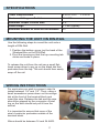
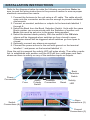
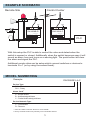
C onnectivity for the 21st Century
SW1008RLY-X-C/R
SW1008POL-X-C/R
Installation Manual
WCABLE-M-001
Rev 1.5
May 2nd, 2012
HAZARDOUS LOCATIONS
The Wireless Wire system has been listed to Ul1604 & CSA 22.2 # 213M1987 for use in Class 1 Div. 2 Groups A,B,C & D hazardous locations. In
order to comply with the UL and CSA standards, the installation must follow
the requirements of the NationalElectric Code Article 501-4(b) and/or
Canadian Electric Code 18-156 when installing a system in a hazardous
location.
WARNING – EXPLOSION HAZARD – SUBSTITUTION OF COMPONENTS
MAY IMPAIR SUITABILITY FOR CLASS I, DIVISION 2
AVERTISSEMENT – RISQUE D’EXPLOSION – SUBSTITUTION
DECOMPOSANTS PEUT RENDRE CE MATERIEL INACCEPTABLE POUR
LES EMPLACEMENTS DE CLASSE I, DIVISION 2
WARNING – EXPLOSION HAZARD – DO NOT DISCONNECT EQUIPMENT
UNLESS POWER HAS BEEN SWITCHED OFF OR THE AREA IS KNOWN
TO BE NON-HAZARDOUS
AVERTISSEMENT – RISQUE D’EXPLOSION – AVANT DE DÉCONNECTER
L’ÉQUIPMENT, COUPER LE COURANT OU S‘ASSURER QUE
L’EMPLACEMENT EST DÉSIGNE NON DANGEREUX
DESCRIPTION
The Wireless Wire system provides two banks of eight switch inputs/outputs
to be sent wirelessly between up to 32 remote locations. Each of the eight
terminals on each unit can function as either a switch input or a switched
output. When a switch, connected to a unit, is closed the corresponding
terminal on all other units of the same bank will behave as closed switched
outputs to ground.
The system uses Zigbee technology to create a mesh network between all
the nearby nodes which allows for much larger distances to be covered by
the radios. If a remote location is too distant to connect to the network
another node located midway can act as a repeater for the first unit.
Each network must contain precisely one coordinator node (usually located
at the control centre). A coordinator node that detects a pre-existing network
will not function correctly.
Each unit has a switch to select one of two banks. Units will only
communicate with other units that have the same jumper setting. Other
models are available with 16 terminals that provide access to both banks
simultaneously.
1
SPECIFICATIONS
Power Requirements
8 to 24 V DC
Maximum Voltage on Switches
60 V DC
Maximum Output Current Sink
2A
Radio Range
> 1 km (typical)
Maximum Number of Units on the Network
32
MOUNTING THE UNIT ON DIN-RAIL
Use the following steps to mount the unit onto a
length of DIN-Rail.
1. Position the bottom grove (on the back of the
WirelessWire on the DIN-Rail.
2. Pivot the housing so that the top mounting tab
clicks and locks in place.
To release the unit from the rail use a small flathead screw driver to pry up on the black tab that
protrudes from the top. The unit should then easily
snap off the rail.
WIRING INSTRUCTIONS
For each wire you wish to connect, strip it’s
jacket between 1/4" and 1/2". Then, using a
small screwdriver press down on the orange
tab at the front of the terminal block and
insert the wire. Release the tab and the wire
should be gripped by the connector. A brief
tug on the wire should not pull it from the
socket.
It is important to ensure that none of the
wire’s conductor protrudes outside of the
terminal block.
Wires should be between 16 and 24 AWG.
2
< 0.25 A
INSTALLATION INSTRUCTIONS
Refer to the diagrams below to make the following connections. Note: be
sure to read the wiring instructions in the previous section to ensure proper
electrical connections are made.
1. Connect the Antenna to the unit using a uFI cable. The cable should
snap onto the connector and be secure enough to prevent accidental
disconnects.
2. Connect, as needed, switches or outputs to the terminals labelled 1
through 8.
3. Select the Bank from the Bank Selection Switch. Units with the same
Bank number can communicate with the Switches of another unit.
Note: this must be set prior to the power being applied.
4. Select the desired alarm polarity. With the switch in the ON state
alarms will be triggered when switches go from closed to open.
Otherwise alarms will be triggered when switches go from open to
closed.
5. Optionally connect any alarms as required.
6. Connect the power source to the unit with ground on the terminal
labelled ‘-’ and power on the terminal labelled ‘+’.
Once the unit is powered the activity LED will pulse slowly. Then after a radio
link is established with another unit the LED will turn solid green and flash
whenever there is activity on any of the switches inputs or outputs.
Bank
Selection
Switch
Power
Connection
Fuse
Alarm
Polarity
Switch
Antenna
Connection
Reset
Activity
LED
Alarm
Connections (2)
Switch
Connections (8)
Ground
Connections (3)
3
ALARMS
The behaviour of the alarm depends on the model of the unit. The alarm
connections behave as switched outputs to ground. An alarm condition is
defined by the state of the alarm polarity switch as either a switched input
going from open to closed or from closed to open.
MODEL SW1008RLY-A-C/R
Both alarm outputs are set closed if any of the 8 inputs exhibit an
alarm condition
MODEL SW1008RLY-B-C/R
If any of the first seven inputs exhibit an alarm condition then both
alarm outputs are closed. The eighth switch input is used as an
acknowledge which will clear the first alarm pin after it is closed. In
this case, switch eight is not relayed to the other devices.
MODEL SW1008RLY-C-C/R
If inputs, four to seven exhibit an alarm condition – both alarm
outputs are closed. The eighth switch input is used as an
acknowledge which will clear the first alarm pin after it is closed. In
this case, switch eight is not relayed to the other devices. Inputs one
to three have no effect on the alarms.
Device Type
Relay
All of the switch inputs between all units on the network with the
same channel selected will be relayed. If the I/O daughter board is
present the channel is ignored and only the switches on the I/O
daughter board are used as the second channel.
Polled
This will not relay the switch closures between units. The only way to
retrieve or set the values of the switches is through a USB Device
unit somewhere on the network.
PACKAGE CONTENTS
Ÿ Wireless Wire Unit
Ÿ Installation Manual
4
EXAMPLE SCHEMATIC
Remote Site
Control Center
24V
24V
24V
+-
+-
24V
SW1008B-R
SW1008A-C
1 2 3 4 5 6 7 8 COMMON ALARM
1 2
1 2 3 4 5 6 7 8 COMMON ALARM
1 2
PLC
PB
(ALARM ACK)
With this setup the PLC is able to control the valve and detect when the
switch is opened or closed. Additionally when the switch becomes open it will
sound an alarm horn and turns on a warning light. The push button will clear
the alarm and signal the PLC.
Additional remote sites can be setup which connect switches or devices to
terminals 3 to 7 (or by using the second bank).
MODEL NUMBERING
Example:
SW1008RLY-A-C
Device Type
POL - Polled
RLY - Relay
Alarm Code1
A - Simple Alarm
B - Acknowledged Alarm
C - Partial Acknowledged Alarm
Device Network Type
C - Coordinator2
R - Remote
1. See the ‘Alarms’ section above for more details.
2. Every network must have precisely one Coordinator device
5
TROUBLE SHOOTING
Problem: The LED does not flash after applying power to the unit.
Possible Solutions:
Ÿ Check that the power is properly connected and making contact.
Ÿ Ensure the power supply voltage is correct: between 8V and 24V.
Ÿ Check that the fuse has not blown. If it has replace it with an
equivalent 1/4A fuse.
Problem: The LED flashes but never turns solid green.
Possible Solutions:
This indicates a problem with the radio link between nodes.
Ÿ Ensure that the antenna is connected properly and positioned in a
reasonably open space with no metal surfaces close which shield it.
Ÿ The unit may be out of range. Try inserting another unit midway
between it and the nearest node.
Problem: Multiple nodes have a solid green LED but switch closures do not
get sent between them.
Possible Solutions:
Ÿ The nodes may be set to different banks. Ensure that the switch bank
jumper on all the nodes is the same.
Ÿ Check the connections. If the LED doesn’t flash when a switch
changes state it may indicate the switch is not correctly connected. If
the LED does flash it may indicate the output is not correctly
connected.
6
LIMITED PRODUCT WARRANTY
Deltatee Enterprises Ltd. (Deltatee) warrants, to the original purchaser, this
product against defects in materials or workmanship for a period of one (1)
year from the date of original purchase. During this period Deltatee will repair
or replace a defective product or part, at their discretion, with a new or
refurbished product without charge FOB Deltatee. No warranty shall apply
when damage is caused by or repair is required due to any of the following:
1. Use of the product outside of its intended purpose or application it was
designed for;
2. Use of an improper power source;
3. Accident, alteration, abuse or misuse of the product or;
4. Fire, wear, damage, theft, war, riot, hostility, or Acts of God.
These warranties and remedies are exclusive and all other warranties,
express or implied, written or oral, including the implied warranties of
merchantability or fitness for any particular purpose are excluded.
To receive warranty consideration a RMA must be obtained and the defective
product returned to Deltatee.
PRODUCT LIABILITY
Deltatee shall not be liable for any loss, damage (including without limitation,
direct or indirect damages for personal injury, property damage, loss of
business profits, business interruption or any other pecuniary loss) or
expense arising directly or indirectly out of the purchase, installation or
operation of its products. In no event shall Deltatee be liable for special,
indirect, incidental or consequential damages of any kind or nature due to any
cause. Deltatee neither assumes or authorizes any representative or other
person to assume for it any obligation or liability other than is expressly set
forth herein.
The laws of the province of Alberta, Canada, govern this agreement, the
products and accompanying instructions and manuals. The purchaser and
any other related parties, further agree that any litigation shall be commenced
in the courts in the city of Calgary in the province of Alberta, Canada.
CONTACT INFORMATION
Deltatee Enterprises Ltd.
202, 1439 - 17th Avenue SE
Calgary, Alberta
Canada T2G 1J9
Phone: 1-403-250-3533
Fax: 1-403-263-2170
Email: [email protected]
7