1
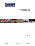
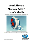
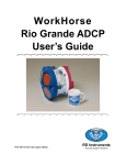
HydroLink ML3 Series
Wireless Data Transceivers
For
Internal GPS DSM132/232 and P66 Depth Sounder
Quick-Start Guide
and
User’s Manual
110 Copperwood Way, Suite E
Oceanside, CA 92054
760.754.2400
1
Table of Contents
Title
Page Number
Quick-Start Guide ...............................................................................................................3
Overview ..............................................................................................................................4
Section 1: Configuring the ADCP ....................................................................................4
Section 2: Configuring a secondary instrument ............................................................5
Section 3: Remote transceiver setup ................................................................................5
Section 4: Base transceiver setup and system power up ..............................................9
Section 5: WinRiver setup.................................................................................................10
Section 6: Connections and wiring ..................................................................................11
Section 7: Power requirements.........................................................................................11
Section 8: Antennae requirement.....................................................................................11
Section 9: RS232 interfacing..............................................................................................12
Section 10: Troubleshooting ..............................................................................................13
Section 11: Technical specifications ..................................................................................14
Section 12: Regulatory information ..................................................................................14
Section 13: FCC notification...............................................................................................14
2
QUICK START GUIDE FOR THE OCEANSCIENCE RIVERBOAT
Using an RD Instruments WorkHorse series ADCP
If this is the first time you have used your Oceanscience Riverboat system we highly recommend
you familiarize yourself with the setup procedures prior to field deployment. Testing in the office
can save valuable field time. While testing the transceivers in close proximity it is advisable to
unscrew the MaxRad antenna from the boat. This avoids the possibility of over-modulation.
The most important phase of setup is configuring your ADCP so that it will communicate through
the modems. This is done by setting the baud rate of the ADCP to 19,200 bps. This matches the
baud rate of channel 1 of your HydroLink ML2. (See section 1, Configuring the ADCP, for details
on how to do this).
The next step is to install the ADCP and GPS on the Riverboat (see Riverboat Assembly
Instructions).
Install the Remote transceiver in the Riverboat (see section 3, Remote transceiver setup).
Establish communications between your transceivers by completing section 4, Base Transceiver
Setup and System Power up.
Confirm ADCP data transmission through the transceivers (section 5, WinRiver Setup).
You can confirm GPS data transmission in the same manner but, your GPS antenna must have an
unobstructed view of the sky.
If you are receiving data from both sensors you can simply turn off the Riverboat toggle and
disconnect power to your Base transceiver. Once in the field, you can apply power and should be
ready to begin your discharge measurements.
Antenna Port A/ Port B/ Port C/
Com 1 Com 2 Com 3
3
Overview
Thank you for purchasing an Oceanscience Group product. It is our intention to provide our
customers with the latest technologies, the highest quality manufacturing and the most efficient
customer service and support. This manual outlines the use of HydroLink ML2 series Wireless
Data Transceivers with specific references to their use with The Oceanscience Riverboat for ADCP
deployment.
Simply put, the HydroLink transceivers eliminate the need for data transmission cables.
Please note: The transceivers have a fixed data transmission rate (baud rate). In order to send
data through them, your instruments and laptop or other receiving device must be set to the
same baud rates as those installed in the transceivers. The default baud rates for your ML2
series transceiver are 19,200 bps for Com 1 and 4800 Bps for Com 2. This rate is optimized and
cannot be altered except by The Oceanscience Group. The HydroLink ML2 Wireless Data
Transceivers are pre-configured for high-speed data communication and each pair is programmed
to communicate only with one another.
Configuring the ADCP: Com 1, Baud Rate of 19,200 Bps
The following procedure explains how to set the baud rate and save it in the ADCP. This procedure
assumes that you will be using the program BBTalk supplied by RD Instruments.
Begin by configuring the baud rate of the ADCP to match the baud rate of the radio. If these do
not match, the ADCP cannot communicate through the transceiver.
1. Connect the ADCP to the computer and apply power (see the appropriate
ADCP User's Guide).
2. Start the BBTalk program and establish communications with the ADCP by choosing
Workhorse, the appropriate Com, and Next. If this is the first time using the Workhorse choose
Next at the “Port Settings” window. When the “Options” window appears place a check in
the boxes labeled Send CK on baud rate change, and Use Software Break.
3. Wake up the Workhorse by sending a break signal with the blue (===) button.
4. Send the command CR1 to enter setup.
5. Find the baud rate on the table below that matches the baud rate of your Oceanscience
HydroLink transceivers (Com 1/ADCP port = 19,200 Bps). Send the corresponding
CB command.
Table 1: Baud Rate
Baud Rate
4800
9600 (default)
19200
38400
57600
115200
CB Command
CB311
CB411
CB511
CB611
CB711
CB811
6. In BBTalk, press F5 and change the settings to match your CB command settings. Press OK to
exit the communication setup screen.
4
7. Send the command CK to save the new baud rate setting (this may not be necessary if there is a
check in the box “send CK on baud rate change”).
8. Click File, Close to exit the terminal window.
The ADCP is now set for the new baud rate. (The baud rate will stay at these settings until you
changed back with the CB-command.)
Configuring a Secondary Instrument: Com 2, Baud Rate of 4800 Bps
The baud rate of your GPS, echo sounder, or other secondary device must match the Com 2 baud
rate. When you are setting an instrument’s baud rate you are setting its RS232 data rate. Note: If
using an Oceanscience supplied instrument, the baud rate has been pre-set to the correct rate.
When instrument set up is complete, install both instruments on the Riverboat (see the separate
Riverboat Assembly Instructions for basic Riverboat assembly).
Remote Transceiver Setup
The ADCP is now ready to communicate with
the laptop through the HydroLink transceivers.
Use the following procedure to install the
transceiver, GPS unit and battery in the
Riverboat electronics compartment, and to
connect the externally-mounted depth sounder.
Please note Figure 1: the identity of the internal
cables and external equipment is as follows:
upper left - GPS antenna; upper right - ADCP
data cable; lower right - depth sounder cable;
lower left- MaxRad stub antenna for Hydrolink
transceiver. Also note the smaller battery wires
(pinned to the hatch collar with tape, which will
make installation easier). A single red power
wire originates from the on/off switch, and one
black power wire originates from the ADCP
cable. (Fig 1.) (FYI: There is an additional
internal battery wire that runs from the on/off
switch to the ADCP cable. It is connected and
tucked into the back of the compartment, behind
the white foam compartment liner, and need not
be disturbed.)
Figure 1. Electronics compartment ready for
equipment.
Also note the two loose cables: the GPS data
jumper cable (Fig. 2), and the depth sounder
data connector cable (Fig. 3).
Figure 2. GPS Data Jumper
5
All data connectors (four yellow, one black, one
in-line) are keyed and will only attach when
oriented correctly. Do not force these
connectors. The threaded antenna connectors are
not keyed.
Begin by placing the Hydrolink transceiver and
the Trimble GPS units on end inside the hatch as
shown in Figure 6.
Connect the MaxRad stub antenna cable to the
Hydrolink transceiver, and connect the GPS
antenna cable to the GPS receiver.
Now the data cables: connect the ADCP data cable
to Hydrolink transceiver port A. Connect the data
jumper cable to port B on the Hydrolink and Port
A on the GPS receiver. Attach the depth sounder
connector cable to its internal mate (this small
threaded in-line connector is keyed), and attach its
yellow data connector to Port C on the Hydrolink
transceiver. Slide the transceiver and the GPS
unit into the compartment, and then nest two of
the foam spacers between them and towards the
bow, as shown (Fig. 5). Place the other small
foam spacers against the stern. These will keep
the battery from traveling during deployment.
Finally, place the battery between the GPS and the
transceiver, and add the thin foam spacers on
either side (see fig. 8). You’re ready for power
connection.
Figure 3. Depth sounder internal data
connector cable.
Battery note: We’ve provided two 7.2 amp-hour
batteries with your system. Expect about 5
hours of service from each fully charged battery
in the field.
Be sure the power switch is off. Install the
ground wire splitter (Fig. 2) onto the black battery
terminal. Attach the black wire from the data
jumper cable to one of the splitter’s connectors,
and the black wire from the ADCP data cable to
the other splitter connector.
The fused red power wire originating from the
on/off switch attaches to the red battery terminal;
connect the remaining red wire from on/off
switch to the red wire of the data jumper cable.
6
Standard Crossbar: Attach the GPS antenna
mount to the standard crossbar using the ¼ -20 x
by 5/8 inch buttonhead screws, with flat
washers, inserted from the bottom of the
crossbar and secure in place with the nylock
nuts (Fig. 7).
For the Sliding Crossbar: attach the antenna
mount with the 3/8” buttonhead patch screw and
flat washer inserted from the top (Fig. 9).
Figure 5. Electronics compartment foam,
battery and instrument arrangement.
Install the depth sounder on the transom as shown
in Figure 11.
Install the GPS dome antenna on the antenna
mount. (You’ll need to remove the metal thread
adapter from the bottom of the dome antenna.)
Connect the antenna cable from dome antenna to
Figure 6. GPS unit and transceiver with data
and antenna cables connected.
Figure 8. Equipment nested with foam spacers;
power wires connected.
Figure 7. Antenna mount on standard crossbar
7
Figure 10. GPS dome antenna and antenna
cable installed.
Figure 9. Antenna mount on sliding crossbar
Figure 11. Depth sounder installed on
Riverboat transom.
8
Base Transceiver Setup and System Power up
Setup for your base system is done using the cables supplied. Figure 11 shows the equipment
needed for your base system.
HydroLink ML3 “Base” unit
Figure 11
MagMount Antenna
P66 Data Cable
DSM 132 GPS Cable
ADCP Base Cable
Attach the base unit antenna. Apply power to the base through the black Kobiconn DC connector
with either a DC power adapter or an ADC wall transformer. The base LEDs should all be red at
this point.
Flip the toggle switch on the Riverboat to turn on the power. (Confirm power to your instrumentsis your battery charged?)
Shortly after both units are powered up they should establish a communications link with each
other to complete the connection. Refer to Table ML3-1 below to confirm that a proper link has
been established. This table is also printed on both transceivers. (In this initial test condition, with
ADCP and both transceivers powered up and the laptop off, transceiver LEDs should conform to
line two on the table “link established, remote sending data”.)
Table ML3-1
Status
Remote Transceiver
Base Transceiver
LED 1 LED 2 LED 3 LED 1 LED 2 LED 3
Power On, No Link SR
SD
SR
SR
O
BR
Link Established,
Remote sending
SG
IF
IF
SG
IF
IF
data
Link Established,
SG
SR
SR
SG
SD
SR
Remote sending
data
Link Established,
SG
SD
SR
SG
SR
SR
Base sending data
Setup Mode
SG
SG
SG
SG
SG
SG
9
Legend:
BR Blinking Red
IF Intermittent Flash Red
O Off
SD Solid Red, Dim
SG Solid Green
SR Solid Red, Bright
WinRiver Setup
Start the base PC and the corresponding application software.
Open your Acquire version of WinRiver. Go to settings and open the heading communications. Click
add, then Broad Band ADCP, then Next. You will be asked “on which port is it attached?” Port
identification may be different for each laptop so make sure the correct port is chosen. Once you
have chosen a port and clicked next, you will be prompted for the baud rate. Select the same baud
rate that is being used by the HydroLink transceivers and ADCP. Set parity at none and stop bits at
1. Click next and be prepared to wait a few seconds. The general screen should appear with two
boxes; check use software Breaks (===) only. Click finish. If you have other devices, such as a GPS or
depth sounder, continue to add them using these same steps. If you have no other devices, move
on to the next step.
Setup the ADCP using the ADCP Configuration Wizard according to USGS standard practice.
Now you’re ready to tryout your ADCP. First, turn the Riverboat power switch on and confirm
that LED 1 on the remote transceiver is green. If it is, choose acquire and start pinging in WinRiver.
The control window will appear, followed by the ADCP wakeup message and you will begin to
hear a quiet pinging noise coming from your ADCP.
Congratulations! Your system is ready to begin making river discharge measurements!
10
Reference Information
Connections and Wiring
The HydroLink ML2 supports RS 232 with an 8-pin circular Micro-Change connector. The ML2 is
designed to operate as a DTE (Data Terminal Equipment). When connecting to a DCE (Data
Communication Equipment), a straight cable should be used. When connecting to another DTE, a
crossover serial cable must be used. The crossover cable must have TD and RD crossed (pins 2-3
and 3-2).
The Base Transceiver should be connected to the computer. The Remote Transceiver should be
connected to the instruments. Transceivers are provided as a matched pair that communicates only
with each other. Each unit of the pair (set) is programmed with a unique serial number ID.
When using the cables provided by The Oceanscience Group, note that the 8-pin circular connector
is keyed and will not align in any way except in the correct alignment. Once the keyway is
properly aligned, the backshell of the connector should be screwed to finger tightness. This
connector is IP68 rated when properly connected.
The antenna connector is type TNC and care should be given so as to not cross-thread the
connector. Again, finger tight is adequate when threading on the antenna cable.
Power Requirements
The HydroLink ML series transceiver should be powered from a ‘clean’ DC power source. Input
voltage range must be between 10V and 14V.
Power source should be capable of supplying a peak current of 1.0 Amp.
Power cable to the transceiver should be routed away from the antenna. Close proximity between
the two may result interference.
Transceiver input power is reverse-polarity protected.
Antennae Requirements
When purchased as part of The Oceanscience Group Riverboat System, the remote (boat)
transceiver utilizes a rugged 2.4GHz/900MHz antenna, while the base unit comes equipped with
an omni-directional antenna. All antennae, their connectors and cables have 50ohms of impedance.
Using other antennae, connectors, or cabling could result in unsatisfactory results.
Placement of your HydroLink ML2 base unit may have a significant impact on its performance. In
practice you should also place the transceiver away from computers, telephones, answering
machines, and other similar equipment.
11
Generally, the higher the antenna, the better the communications link - height is everything! To
improve the data link, Oceanscience offers directional and omnidirectional antennas with cable
lengths ranging from 3 to 200 feet and of varying gain.
When using an external antenna, placement of that antenna is critical to a solid data link. Other
antennas in close proximity are a potential source of interference. It is also possible that slight
adjustments in antenna placement (as little as 2 feet) will solve noise problems. In extreme cases,
such as when the transceiver is located close to pager or cellular telephone transmission towers,
noise may be reduced by special filters available from Oceanscience.
RS232 Interface
Because the transceivers’ serial data parameters are fixed, instruments and any related application
PC software must be set to match. The serial data rates for the HydroLink ML2 are 19,200 Bps on
Com 1 and 4,800 Bps on Com 2.
When configuring the instrument and application software to match the transceiver, the PC and
instrument should be connected directly. If using a GPS provided by Oceanscience there is no need
to change the baud rate as they are configured at the factory.
Do not attempt to change instrument settings using the transceivers. Communication is not
possible until the instrument and application software settings match those of the transceivers.
Some instruments transmit or receive control pulses using the computer RS232 com port. Because
the transceivers transfer binary data, with a pre-defined data byte length, attempting to send
control pulses using the transceivers is not recommended. A specific example of this is the “wakeup” or break command used by some ADCP manufacturers. The standard “wake-up” command is
a 300 ms pulse sent from the computer comm port to the ADCP. If this pulse is routed through the
transceivers, it will not be recognized by the ADCP. The solution to this format conflict is to use the
ADCP alternate “wake-up” command of three ASCII equals signs” = = = “. Using this alternate
control command maintains the binary data format and will be recognized by the ADCP through
the transceivers.
Some GPS instruments transmit and receive data using the NMEA 0183 V3.0 or higher spec. This
specification calls for a RS-422 transmission format, not RS-232. All instrumentation connected to
the transmit and receive data lines of the transceiver should be verified to use RS-232 format.
12
If using a Trimble DSM132 and you experience garbled data or are having problems establishing
communications with your GPS, you should restore the unit to factory settings by performing the
following steps:
•
•
•
•
•
Press the v arrow 6 times. This places you at the Clear BB RAM? screen.
Press > once to highlight the No.
Press v once to change to Yes.
Press the enter key and all factory defaults will be restored.
Troubleshooting
This section lists some problems that you might encounter while using your HydroLink ML2
transceiver:
Symptom
Possible solution
I cannot connect.
• Make sure that you have connected power to your transceivers. The LED
indicator should emit a green light when powered up, being ready to send and
receive data then turning blue.
• Your remote instrument is not configured to use the same serial settings (e.g.
baud rate) as your HydroLink ML2.
• Your transceivers are too far away from each other. Move them closer or raise the
base antenna.
• Check all cabling connections.
The link between my
transceivers
disconnects.
• There is substantial interference.
• Your transceivers are too far away from each other. Move the two devices closer
to each other or raise the base antenna.
There is no color on
the LED indicator.
• Make sure that power is connected to the device by checking: data/power circular
connector on HydroLink face, quick-disconnects, battery connections are polarity
correct, Kobiconn DC adapter is connected, toggle switch is in the “on” position.
I’m receiving data but
it’s garbled.
• Verify the baud rate on your data instrument matches the baud rate of your
HydroLink ML2. If your GPS is Trimble DSM132, restore unit to factory defaults
(see section 5, RS-232 Interfacing).
I have no power.
• Check your battery, battery connections, and fuse.
13
Technical Specifications
Frequency
902 to 928 MHz
Transmitter Output Power
1mW to 1W (+30 dDm)
Range
*60miles
Modulation
Spread Spectrum GFSK, 120 kBs – 170 kBs
Spreading method
Frequency hopping
Occupied Bandwidth
230 kHz
System gain
140 dB
Error Detection
32 Bit CRC, resend on error
Forward error correction
Golay, retransmit on uncorrectable error
Data Encryption
Substitution, dynamic key
Max Link Throughput
115 Kbaud standard speed
Data Interface
RS-232/RS485
Operating Modes
Point-to-Point, Point-to-Multipoint, Repeater
* Line of sight distance with unity gain antenna
** Throughput measured assuming 75% frequency availability
Regulatory Information
FCC Identifier KNY21161341911919
DOC Identifier 2329 102 336A
FCC Notification
This device complies with part 15 of the FCC rules. Operation is subject to the following two conditions: 1) This device
may not cause harmful interference and 2) this device must accept any interference received, including interference that
may cause undesired operation.
This device must be operated as supplied by The Oceanscience Group. Any changes or modifications made to the device
without the express written approval of The Oceanscience Group may void the user's authority to operate the device.
CAUTION: The transceiver has a maximum transmitted output power of 955mW. It is recommended that the transmit
antenna be kept at least 23 cm away from nearby persons to satisfy FCC RF exposure requirements.
Note: This equipment has been tested and found to comply with the limits for a Class B digital device, pursuant to part 15
of the FCC Rules. These limits are designed to provide reasonable protection against harmful interference in a residential
installation. This equipment generates, uses and can radiate radio frequency energy and, if not installed and used in
accordance with the instructions, may cause harmful interference to radio communications. However, there is no
guarantee that interference will not occur in a particular installation. If this equipment does cause harmful interference to
radio or television reception, which can be determined by turning the equipment off and on, the user is encouraged to try
to correct the interference by one or more of the following measures:
• Reorient or relocate the receiving antenna.
• Increase the separation between the equipment and receiver.
• Connect the equipment into an outlet on a circuit different from that to which the receiver is connected.
• Consult the dealer or an experienced radio/TV technician for help.
This product is licensed by The United States. Diversion contrary to U.S. law is prohibited. Shipment or re-export of this
product outside of The United States may require authorization by the U.S. Bureau of Export Administration. Please
contact The Oceanscience Group for additional information or assistance.
14