1
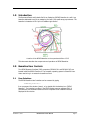
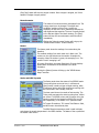
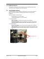
REIXS Beamline User Manual (Work in Progress) Feizhou He Updated: November 7, 2011 TABLE OF CONTENTS 1.0 Introduction ................................................................................................ 1 2.0 Beamline User Controls ............................................................................. 1 2.1 3.0 4.0 User Interface .......................................................................................... 1 2.1.1 Shutters, Valves and Vacuum Pressure........................................ 2 2.1.2 Beamline Parameters Monitoring .................................................. 3 2.1.3 Additional Controls ....................................................................... 5 2.2 Setup Endstation Branch.......................................................................... 5 2.3 Selecting Energy Range and Polarizations............................................... 6 2.3.1 Selecting M2 Coatings and Gratings............................................. 7 2.3.2 Selecting EPU Harmonics and Photon Polarization ...................... 7 2.4 Setup Chopper ......................................................................................... 8 2.5 Opening the Beamline to the Ring ............................................................ 8 2.6 Getting the Beam into the Endstation ....................................................... 9 2.7 Beamline Monitoring and Diagnostics .................................................... 10 2.8 Other ...................................................................................................... 11 RSXS Endstation ..................................................................................... 12 3.1 Instruments ............................................................................................ 12 3.2 Motion Control........................................................................................ 14 3.3 Data Collection Software ........................................................................ 15 XES Endstation ........................................................................................ 15 4.1 Instraments ............................................................................................ 15 4.2 Motion Control........................................................................................ 15 4.3 Data Collection ....................................................................................... 16 November 7, 2011 REIXS Beamline User Manual Page i 1.0 Introduction The Resonant Elastic and Inelastic Soft X-ray Scattering (REIXS) Beamline is a soft X-ray beamline dedicated to soft X-ray scattering and soft X-ray spectroscopy experiments. The beamline is located at 10ID-2 port of Canadian Light Source. Location of the REIXS Beamline on the experimental floor of CLS This document describes the components and operations of REIXS Beamline. 2.0 Beamline User Controls Two REIXS Operator Interface (OPI) computers (OPI1610-201 and OPI1610-202) are located inside the REIXS Cleanroom. The computer operating system is Scientific Linux. Users need to log in to access the beamline control. 2.1 User Interface The REIXS Beamline User Interface can be accessed by typing runREIXS_beamline & from a command line window (xterm), or by double click the desktop icon “REIXS Beamline”. The interface is written in the EPICS display-manager package EDM. It provides user with essential beamline controls. Important error conditions are also displayed in this window. November 7, 2011 REIXS Beamline User Manual Page 1 REIXS Beamline Main User Interface 2.1.1 Shutters, Valves and Vacuum Pressure The upper half of the user interface includes the shutter/valve control, and shows the vacuum pressure along the beamline. The horizontal straight line represents the beam, from the frontend on the left side to the endstations on the right side. The black letters below the beamline are the acronyms of each vacuum component: November 7, 2011 PSH2 Photon Shutter 2 SSH Safety Shutter FM3 Fixed Mask 3 VA Variable Aperture M1A/B M1A and M1B Mirrors PSH3 Photon Shutter 3 4J1 4-Jaw #1 MONO Monochromator 4J2 4-Jaw #2 CHP/ES Chopper and Exit Slit M3/M4 M3 and M4 mirrors PSH4 Photon Shutter 4 M5 M5 Mirror GC Gas Cell XES X-Ray Emission Endstation (UofS) RSXS Resonant Soft X-Ray Scattering Endstation (UBC) REIXS Beamline User Manual Page 2 Shutters are shown as rectangles in or out of the beam, and the valves are double triangles. Click the [Open] or [Close] buttons above each shutter/valve to open or close corresponding shutter or valve. When closed, the shutter or valve is in red color. Open state is in green. The numbers below the name of each vacuum section are the vacuum pressure, in Torr. The number is green when the pressure is less than 10×10-10 Torr, and yellow when the pressure is higher than 1×10⁻⁹ but less than 5×10⁻⁸ Torr. The number is red for pressure higher than 5×10⁻⁸ Torr. The vacuum pressure in any section shall be kept below 1×10⁻⁸ Torr. If vacuum pressure is too high, try using a smaller aperture size on Variable Aperture, or closing the Photon Shutter 3 until the pressure recovers. 2.1.2 Beamline Parameters Monitoring The lower half of the user interface shows the status of the beamline components. The parameters are grouped into several panels. EPU in 10ID The 10ID panel shows the gap and phase information of both REIXS EPU and SM EPU. The polarization of REIXS EPU can be changed using the drop down menu button. The options include: Circular Left, Circular Right, Linear Horizontal, Linear Vertical -, Linear Vertical +, and Linear Inclined. The small circles indicate the status of the respective motors, green means “Move Done”, yellow means “Moving”. The EPU Harmonics selection button can be used to select which harmonics shall be used for the energy range. Apertures The Aperture panel shows the gap and position of each aperture. H – horizontal, V – vertical. The setpoints for the Variable Apertures can be changed from this panel. The setpoints are in purple color, and the feedback values are black numbers above each input boxes. The small circles indicate the status of the respective motors, green means “Move Done”, yellow means “Moving”. Chopper The speed and position of the chopper can be set in the Chopper panel. Use ONLY positive numbers for the “Speed” and “Move Relative” input. One revolution per second equals to 12 Hz switching. The blue numbers shows the current speed and position of the chopper. November 7, 2011 REIXS Beamline User Manual Page 3 Click [Stop] button will stop the chopper rotation. Once chopper is stopped, use “Move Relative” to adjust chopper position. Monochromator The status of the monochromator is displayed here. The energy setpoint can be changed. The angles and translation positions of the mirror / grating are displayed, as well as the error (difference) between the real angles and the setpoints. The error is usually limited to the last two digits of the black numbers. The [Stop] button will stop the monochromator and EPU motions immediately. Clicking the [Monochromater] button will bring up the “REIXS Monochromator” control interface. Meters The Meters panel shows the readings from meters along the beamline. The realtime readings from each meter are in black color. The numbers on the right side shows the number of samples for averaging. When the number is green, the averaging is on. The number is red if averaging is off. PD means Photodiode, Au means Gold Mesh. EM is the Keithley Electrometer connected to the Photodiode in the RSXS Endstation. Clicking the [Meters] button will bring up the “REIXS Meters Setup” interface. Scaler and RSXS Cryostat The Scaler panel shows the status of the SIS3820 scaler. The counting time can be set here, in milli-second. [Scan] button is used to trigger a single counting, while [Continuous] button will trigger continuous counting with the interval set in the Counting Time box. The lower panel shows the results of last counting. The Timing value represents the actual counting time, 10MHz per second. The REIXS column and SM column show the counting results for the beam from REIXS EPU and SM EPU respectively, in the REIXS 2-in-1 operation mode. ChT means Channeltron, TEY means Total Electron Yield, and MCP mean microchannel plate. The RSXS Sample temperature panel is used to display and change the sample temperature in the RSXS chamber. The status of the cryostat and the heater is also shown. November 7, 2011 REIXS Beamline User Manual Page 4 2.1.3 Additional Controls The buttons at the bottom of the user interface will call up additional control panels. Some of them will be explained in the following sections. 2.2 Setup Endstation Branch The REIXS beamline has two endstations: XES and RSXS. At one time the beamline is setup for one of the endstation. Please ask beamline staff if you need to switch endstations. Switching endstation involves two steps: Move M3 mirror in or out of the beam Translate XES endstation in or out of the beam To use RSXS Endstation: M3 in the beam: lift M3 tank until the encoder reach 0.8660mm. XES out of the beam: Loosen the locking nuts on the switch yard on M5 tank. Move XES Endstation backward to limit switch. Hand tighten the locking nuts. To use XES Endstation: M3 out of the beam: lower the M3 tank until the encoder reach -0.XXXXmm. XES in the beam: Loosen the locking nuts on the switch yard on M5 tank. Move XES Endstation forward until encoder reads 0.XXXXmm. Hand tighten the locking nuts. Four locking nuts M5 switch yard November 7, 2011 REIXS Beamline User Manual Page 5 2.3 Selecting Energy Range and Polarizations The “REIXS Monochromator” window is used to setup monochromator and REIXS EPU. In this window, you will be able to set the photon energy and select the mirror coatings and gratings. The [STOP] button on top will stop REIXS EPU and Monochromator immediately. The “Mono Calib” button is used to fine tune the energy calibration. Please refers to Section Error! Reference ource not found. for details. polarization of the photons from the EPU. November 7, 2011 REIXS Beamline User Manual The REIXS EPU panel allows you to select the harmonic of the EPU output, and the Page 6 2.3.1 Selecting M2 Coatings and Gratings The REIXS monochromator has three gratings, and there are four coatings on the M2 mirror. In the “M2 Mirror” and “Grating” panel, user can select which grating and coating are used. The setpoint and feedback values are also displayed. The table below lists the maximum usable range for each combination of the M2 Coating / Grating. For best flux and good higher order harmonics suppression, the optimized range shall be used. Grating Ni-LEG Au-LEG Au-HEG M2 coating Overall Range (eV) Optimized Range (eV) Si (SiO2) 167-525 230-525 Ni 167-800 380-800 Graphite 80-260 80-260 Au 80-1000 Au 400-2000 800-2000 2.3.2 Selecting EPU Harmonics and Photon Polarization Depending on the desired photon energy range, appropriate EPU harmonics shall be selected for optimum flux. For circular polarization, only the first harmonics can be used. The energy range is from 100 eV to 1000 eV. For linear polarization, use the first harmonics for energy between 80 eV and 1000 eV. Use the third harmonics for energy between 800 eV to 2500 eV. Use the fifth harmonics for energy above November 7, 2011 REIXS Beamline User Manual Page 7 1500 eV. When the EPU control is established, the “Access” field shows “ENABLED” The “Polarization” selection button can be used to select photon polarization. Available options are: Circular Left Circular Right Linear Horizontal Linear Vartical - Linear Vartical + Linear Inclined For “Linear Inclined” polarization, the “Inclined Angle” must be set. The angle range is from -90° to +90°. 2.4 Setup Chopper Chopper must rotate in the positive direction for correct operation. If the chopper has moved in negative direction, it must rotate in positive direction for one revolution, so that the encoder can pass the home position reference mark and establish the correct angle readout. LED indicators on the Chopper Controller in the NIM Crate show the status of the chopper system. Once chopper is stopped, use “Move Relative” to adjust chpper position. 2.5 Opening the Beamline to the Ring Once the setup of EPU and monochromator is done, follow steps below to open the beamline to the ring: Open all vacuum valves Go to 10ID POE ACIS panel. After injection, all five lights to the left shall be green. If any of the middle three lights is red, follow the “10ID POE Lockup Procedure” in Appendix. Open the “Safety Shutter” by pushing the big green [Safety Shutters] button. The green light will be on. November 7, 2011 REIXS Beamline User Manual Page 8 From the REIXS user interface, open photon Shutter 2 (PSH2) Open Photon Shutter 3 (PSH3) Open Photon Shutter 4 (PSH4) If any photon shutter cannot be opened, there could be some errors that trigger the interlock system. Possible causes are: vacuum, cooling water, etc. 2.6 Getting the Beam into the Endstation Verify apertures and slits along the beamline. Using the numbers below as a reference. Variable Aperture: Normal Mode: Horizontal Center 14.2 mm, Vertical Center -1.80 mm Horizontal Gap 0 ~ 5 mm, Vertical Gap 0 ~ 5 mm 2-in-1 Mode: Horizontal Center 11.2 mm, Vertical Center -1.80 mm Horizontal Gap 0 ~ 11.6 mm, Vertical Gap 0 ~ 5 mm SM side Variable Aperture needs to be moved out, with Horizontal Center -12.0 mm, Horizontal Gap 0.0 mm 4-Jaw #1: Horizontal Center 0 mm, Vertical Center -1.15 mm Horizontal Gap 20 mm, Vertical Gap 10 mm 4-Jaw #2: Horizontal Center 0 mm, Vertical Center 0 mm Horizontal Gap 20 mm, Vertical Gap 20 mm Exit Slit: November 7, 2011 REIXS Beamline User Manual Page 9 Vertical Gap: usually 10 µm or 25 µm, range is 0 ~ 500 µm Horizontal Center 0 mm, Horizontal Gap 20 mm If the vertical gap of the exit slit needs to be changed, always approach the target value when closing the gap (gap decreasing). 2.7 Beamline Monitoring and Diagnostics Several video cameras are installed along the beamline. The video can be accessed from any computer within the CLS intranet. To access the camera inside 10ID POE Hutch, use the address below in a web browser: http://ccd1610-101.cs.clsi.ca/ To access the cameras along the beamline, use: http://v2e1610-101.cs.clsi.ca/ To access the video of endstations, use http://v2e1610-401.cs.clsi.ca/ There are multiple Beam Diagnostics Assemblies (BD1 to BD5) along the beamline to assist the beam alignment and to diagnose of the problem. Each assembly may have several detectors attached, including photodiode for measuring the flux, gold mesh for measuring the drain current, and YAG Crystal: for visualizing the beam. The Beam Diagnostics can be inserted into or withdrawn from the beam by motorized linear feed-through. November 7, 2011 REIXS Beamline User Manual Page 10 To setup meters in the beamline, click the [Meters] button in the main user interface. The REIXS Meters Setup panel can be used to change most often used parameters for each meter. 2.8 Other November 7, 2011 REIXS Beamline User Manual Page 11 3.0 RSXS Endstation 3.1 Instruments Please refer to the RSXS Endstation User Manual for details. The picture below shows the instruments inside the rack for RSXS endstation. The Ion Gauge controllers on top display the vacuum pressure in the scattering chamber and the load lock. The NIM crate houses the electronics for pulse counting. The SIS3820 Scaler is in the VME crate. Verify the NIM crate and VME crate are working correctly. Below the VME crate is the IOC1610-403 computer. There are several Detectors in the RSXS chamber. To use each detector, following devices are necessary: Chennaltron High Voltage unit NHQ203M Preamp Power Output unit ORTEC 4003 Discriminator unit ORTEC 584 Log/Lin Ratemeter ORTEC 449-2 Scaler SIS3820 Micro Channelplate Micro Channelplate is 3300 Series from Quantar Technology High Voltage unit NHQ203M Position Analyzer Model 2502A including Preamp / Processer Module and Rack Module NIM-TTL-NIM Adapter CAEN N89 or 4-8 Logic Fan-in Fan-out CAEN N454 Scaler SIS3820 November 7, 2011 REIXS Beamline User Manual Page 12 TEY Total Electron Yield is by measuring sample current. Current Preamplifier SRS SR570 Voltage to Frequency Converter NOVA N101VTF NIM-TTL-NIM Adapter CAEN N89 (optional) Scaler SIS3820 Photodiode November 7, 2011 REIXS Beamline User Manual Page 13 The photodiode in the scattering chamber is AXUV100EUT Photodiode from IRD. It can be used for reflectivity measurements, scattering measurements and fluorescence measurements. It is also very sensitive to visible light so the chamber has to be covered carefully when using photodiode. The HCG and RGA must be off as well. Electrometer Keithley 6514 Sample Temperature Control When the cryostat is on, the range of sample temperature in RSXS chamber is from 18K to 400K. ARS Cryostat Temperature Controller Lakeshore 325 Pumps Scattering Chamber: turbo pump, cryopump, ion pump and rough pump Loadlock: Turbo pump and rough pump 3.2 Motion Control The diffractometer in the Scattering Chamber is driven by nine UHV stepper motors from AML. The motors are controlled by spec software. The “RSXS Motors” panel can be used to setup and adjust parameters for all the motors in the Scattering Chamber. November 7, 2011 REIXS Beamline User Manual Page 14 3.3 Data Collection Software The data acquisition is through the spec software from Certified Scientific Software. Please refers to spec manual and “SPEC Macros for REIXS RSXS Endstation” for more details. 4.0 XES Endstation 4.1 Instraments Channeltron MCP 2400 4.2 Motion Control Sample X, Y, Z Detector Rotation Detector Tilt November 7, 2011 REIXS Beamline User Manual Page 15 Detector Translation Spectrometer Rotation Hex-Pot 4.3 Data Collection Custom software November 7, 2011 REIXS Beamline User Manual Page 16