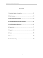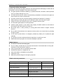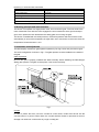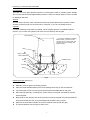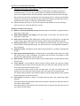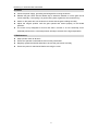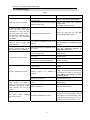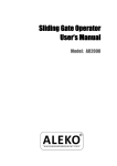
1
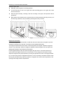
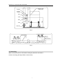
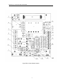
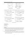
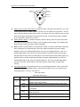
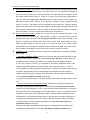
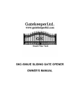
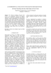
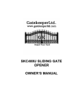
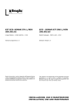
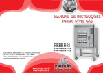
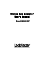
Sliding Gate Operator
User’s Manual
Model: DKC400(U)Y
DKC400 (U) Y SLIDING GATE OPERATOR
OUTLINE
1. Important safety information…………………………3
2. Main features ………………………………………3
3. Main technical parameters …………………………3
4. Working principle and main structure ………………4
5. Installation and adjustment …………………………4
6. Connecting …………………………………………7
7. Control ……………………………………………10
8. Check
……………………………………………15
9. Maintenance ………………………………………15
10. Troubleshooting …………………………………16
2
DKC400 (U) Y SLIDING GATE OPERATOR
1. Important safety information
Carefully read and follow all safety precaution and warnings before attempting to install and use
this operator, incorrect installation can lead to severe injury.
z
The gate operator should be installed by a qualified technician; otherwise, serious personal
injury or property damage may occur.
z
The auto-reverse function must be checked during installation to ensure that the gate can
auto-reverse in the event of obstruction.
z
This auto-reverse function should be regularly inspected and adjusted, if necessary.
z
When opening or closing the gate, do not attempt to walk or drive through the gate.
z
Children should not be allowed to play near or operate automatic gates.
z
The automatic gate operator must be grounded.
z
Install the gate operator on the inside of the property, DO NOT install it on the outside of
the property where the public has access to it.
z
Be careful when in close proximity to moving parts where hands or fingers could be
pinched.
z
Do not allow control devices to be placed so that a person can access them by reaching
through the gate.
z
In the event of power failure, an emergency release key allows you to operate the gate
manually.
z
The operator should be switched off before repairing it or opening its cover.
z
Please erase and reprogram the code after installing the operator.
2. Main features
z
The device is used to drive sliding gate.
z
For your safety, the DKC400 (U) Y will stop and reverse if it was obstructed on closing and
stop when it was obstructed on opening.
z
User programmable and user erasable remote codes.
z
Infrared terminal (N.C) is supplied to use.
z
Auto-close feature is available for this operator.
z
Pedestrian mode.
z
Manual key release design for emergency purposes.
3. Main technical parameters
Tab.1
Model
Power supply
DKC400Y
DKC400UY
AC 220V, 50Hz
AC110V, 60Hz
Motor speed
1400 r/min
1680 r/min
14m/min (24 teeth)
11m/min (19 teeth)
14N·m
17 m/min (24 teeth)
13m/min (19 teeth)
Gate moving speed
Output torque
Limit switch
Remote control operating range
Magnetic limit switch
30m
Frequency
433.92mHz
3
DKC400 (U) Y SLIDING GATE OPERATOR
Remote control mode
Single-button
Auto-close time
0-44 sec.
Working time
90 sec.
Noise
≤62 dB
Environmental temperature
-10 ºC~+55 ºC
4. Working principle and main structure
The device is composed of a single-phase motor, worm and worm gear. The main shaft of the
motor rotates the worm with the clutch engaged, the worm rotates the worm gear and output
gear, which pushes the rack attached to the sliding gate, thus moving the gate.
The device is installed with a thermal protector, the thermal protector will switch off the motor
automatically in case of the temperature is higher than 120°C and switch on the motor when the
temperature is lower than 85°C±5°C.
5. Installation and adjustment
The DKC400(U)Y rack-driven gate operator operates by forcing a drive rack past a drive gear.
The entire configuration is shown in Fig.1. The gate operator must be installed on the inside of
the gate.
Gate preparation
Be sure the gate is properly installed and slides smoothly before installing the DKC400(U)Y
sliding gate operator. The gate must be plumb, level, and move freely.
Fig.1
Conduit
In order to protect the wires, use PVC conduit for control wires, conduit must be set into the
concrete when it is poured. Wires within the conduit shall be located or protected so that no
damage can result from contact with any rough or sharp part.
4
DKC400 (U) Y SLIDING GATE OPERATOR
Concrete pad
The base unit of the gate operator requires a concrete pad in order to maintain proper stability.
The concrete pad should be approximately 300mm x 200mm x 200mm deep in order to provide
for adequate operation.
Anchors
You can use the anchors, bolts, washers and nuts that are provided with the operator. These
anchors must be set into the concrete when it is poured, or you can use wedge anchors.
Operator
In locations where ground freeze is possible, mount the gate operator on installation pad as
shown in Fig.2. Check the operator and make sure it is lined up with the gate.
Gate operator
﹡If you have installed an external
button switch, you must use two
conduits: one for main power wire,
another one for low voltage wire
(button switch).
Gear
Nut
Spring washer
Plain washer
Nut
Anchor
Installation pad
Bolt
Conduit
Wires
Fig.2
Installing the rack (see Fig.3)
Weld the steel rack
z
Manually move the gate to its closing position.
z
Place the three threaded pawls (in the same package with rack) on the rack element.
z
Lay the first piece of rack on the gear and weld the first threaded pawl on the gate.
z
Move the gate manually, checking if the rack is resting on the gear, and weld the second
and third pawls.
z
Bring another rack element near to the previous one. Move the gate manually and weld the
three pawls as the first rack, thus proceeding until the gate is fully covered.
z
When the rack has been installed, to ensure it meshes correctly with the gear.
z
The space between rack and gear is about 1mm.
5
DKC400 (U) Y SLIDING GATE OPERATOR
Screw the nylon rack
z
Manually move the gate to its closing position.
z
Lay the first piece of rack on the gear and mark the drilling point on the gate, drill a hole
and screw the bolt.
z
Move the gate manually, checking if the rack is resting on the gear, and repeat the above
operations.
z
Bring another rack element near to the previous one. Move the gate manually and carry out
the securing operations, thus proceeding until the gate is fully covered.
Fig.3
Magnets for limit switch
To ensure safety, it is recommended to install limit devices at both ends of the gate to prevent
the gate from sliding out of the rails. The rails must be installed horizontally.
The magnet and limit switch are used to control the position of the gate. Install the magnet as
shown in Fig.4 and Fig.5. When the magnet is installed, release the gear clutch and push the
sliding gate manually to pre-determine the position.
Fit the magnet bracket to the rack and then tighten the gear clutch. The lower bracket is for
open position and higher bracket is for close position. Fix the magnet to the bracket. Finally
adjust the magnet to the proper position by moving the gate with the motor. The magnet should
be 10~15mm away from the magnetic limit switch, if it is too far away, the switch will fail to work.
Moving the gate electrically, adjust the position of magnetic limit switch until the positions of the
opening and closing meet the requirement.
6
DKC400 (U) Y SLIDING GATE OPERATOR
10-15mm
Magnetic limit
switch inside
Magnet
Magnet
bracket
Gate
Pawl
122mm
Rack
Gear
Guide rail
Fig.4
It can be adjusted
Lower bracket
Magnet
Rack
Higher bracket
Fig.5
6. Connecting
Make sure that the power is OFF before making any electrical connections.
Perform the wiring (See Fig.6 KZB13 control board)
7
DKC400 (U) Y SLIDING GATE OPERATOR
Fig.6 KZB13 Control Board Scheme
8
DKC400 (U) Y SLIDING GATE OPERATOR
Wiring notes for control board (KZB13)
1.Fuse: DKC400Y: 5A, Ø5x20; DKC400UY: 10A, Ø5x20
2. Power Input: E (Earth), L (Live), N (Neutral) DKC400Y: AC220V; DKC400UY: AC110V
3. Motor: U (com), V (Positive direction), W (Opposite direction), E (grounding)
4. Capacitor: 14uF
5. Alarm lamp: DKC400Y: AC220V; DKC400UY: AC110V
6. Sampling transformer: 220V/12V 1W
7. Force Adjustor (VR): Clockwise +, Counterclockwise –
8. Power Transformer: DKC400Y 220V/12VX12V 7W; DKC400UY: 110V/12VX12V
9. MCU: PIC 16C57C
10. Power indicator: LED
11. Output power supply: AC24V
12. Memory Card: 93C66
13. Limit switch: CL (Close limit), CO (Com), OP (Open limit),DC12V (Output power supply)
CL
CL
COM
COM
OP
OP
N.O. (For N.O. limit switch)
N.C. (For N.C. limit switch)
Limit switch mode is adjustable by DIP-switch. (See table 2)
Schematic diagram
Motor wiring
terminal
Control board
RELEASE CLOSED
SWITCH
OPEN
COM
COM/U
COM
X6
OP
W
MOTOR
REED SWITCHES
CL
V
W
V
U
C
E
C
Wiring diagram
14. Single-button switch / Keypad (normally open, single-button mode): T (Not used), G (Open
priority), K (Open/stop/close), GND(Common)
To install the keypad attach one lead of your keypad to ‘K’ of terminal X7 and the other to the
‘GND’. The keypad will function in single channel mode.
9
DKC400 (U) Y SLIDING GATE OPERATOR
G
NO
com
Not used
T
Open
G
Signal
K
Com
GND
Button switch
keypad
Control board
terminal X7
K
NO
com
Schematic diagram
Wiring diagram
15. Output power supply: +12V (DC +12V), COM (CO),DET (Loop detector), I.R. (Infrared N.C)
COM
COM
I.R
GND
COM
+12V
+12V
Infrared
Terminal
X8, No.15
AC24V Terminal
X5,No.11
AC24V
Control board
Infrared
Control board
Infrared with AC input
COM
COM
Out
DET
GND
COM
+12V
+12V
Loop detector
Out
I.R
Terminal
X8, No.15
Infrared with DC input
COM
COM
COM
Out
COM
Out
DET
Terminal
X8, No.15
AC24V Terminal
X5,No.11
AC24V
Control board
Loop detector
Loop detector with DC input
Terminal
X8, No.15
Control board
Loop detector with AC input
Schematic diagram
16. Beeper: DC12V
17. Learn button: AN
18. Dip-switch
19. Antenna: ANT
7. Control
z
The remote control works in a single channel mode. It has four buttons. See Fig.7 remote
control. The function of button 1, button 2, and button3 are the same. With each press of
the remote control button which has been programmed, the gate will close, stop, open or
stop cycle. Button 4 is available for pedestrian mode.
z
You can program/learn button 1, button 2, button 3 individually. You also can program/learn
two buttons or three buttons together, but you need repeat the program/learn process if you
want to use more than one button.
10
DKC400 (U) Y SLIDING GATE OPERATOR
Button 1
Button 3
Button 2
Button 4
Fig.7
z
Adding extra remote controls (learn): Press the button ‘AN’ (See Fig.6 terminal 17) on the
control board, then the ‘LED2’ will be on and turn off, the beeper will ring about 1 second,
then press the remote control button which you want to use, the ‘LED2’ will turn on and
then turn off again, the beeper will ring about 2 seconds. The learning process is finished.
Up to 100 remote controls may be used.
z
Erase remote controls: To erase all existing remote controls, press and hold ‘AN’ button,
the beeper will ring, release the button once the beeper stops ringing. This indicates that
all the remote controls have been erased completely.
z
Note: Press the ‘OPEN’ button of external button switch or remote control button which has
been programmed, the gate will open, the motor rotates clockwise, the output voltage
between ‘D’ and ‘D’ is AC220V/(DKC400UY: AC110V), the voltage between ‘U’ and ‘V’ is
AC220V/(DKC400UY: AC110V). Press ‘STOP’ button or the same remote control button,
the gate stops running. Press ‘CLOSE’ button or the same remote control button again, the
gate will close, the motor rotates anticlockwise, the output voltage between ‘D’ and ‘D’ is
AC220V/(DKC400UY: AC110V), the voltage between ‘U’ and ‘W’ is AC220V/(DKC400UY:
AC110V). Press the ‘STOP’ button or the same remote control button, the gate stops
running.
z
Verify open direction: If the gate does not move in the desired direction, then you will need
to reverse the motor operating direction, open the black plastic cover, you can do this by
exchanging wires ‘V’ and ‘W’, ‘OP’ and ‘CL’.
Tab.2 DIP-switch
(See Fig.6 terminal 18)
Position
1
DIP-switch
Function
ON
Programming / In this position the control board is in programming
OFF
condition, NOT USE condition.
Normal / In this position the control board can be normally used.
ON
Auto-close function and auto-close function of pedestrian mode
are available.
2
3
OFF
Both Auto-close function and auto-close function of pedestrian
ON
mode are shut off.
Limit switch mode is NC.
OFF
Limit switch mode is NO.
11
DKC400 (U) Y SLIDING GATE OPERATOR
z
Set auto-close function (This feature can be selected to make the gate stay open for some
seconds before it automatically closes. The auto-close time can be adjusted to between 0
and 44 seconds.): please turn on the first and the second DIP-switch to ON position. Press
the remote control button (button 1, button 2 or button 3) that has been programmed to
open the gate (see Verify open direction section). Stop the gate at any position by
pressing the same button, wait for some seconds according to your requirements (the
range is 1~44 sec.), this period of time is regarded as ‘auto-close time’. Close the gate by
pressing the same button. Press the button again to stop the gate or the gate will stop at its
closed position automatically if the limit switch is reached. After this setup is complete,
return DIP-switch 1 to OFF. Thus the auto-close function has been set.
z
Cancel auto-close function: please turn on the first and the second DIP-switch to ON
position. Press the remote control button (button 1, button 2 or button 3) that has been
programmed to open the gate (see Verify open direction section). Stop the gate at any
position by pressing the same button, wait until the gate close automatically (45 sec.).
Press the same button to stop the gate or the gate will stop at its closed position
automatically if the limit switch is reached. After this setup is complete, return DIP-switch 1
to OFF position immediately. Thus the auto-close function has been canceled.
z
Pedestrian mode: Pedestrian mode can be used to open gate about 1.5 meters for people
pass through.
﹡Set width of pedestrian mode: please turn on the first and the second DIP-switch to ON
position. Press button 4 to open the gate (see Verify open direction section), Wait until
the gate travels the distance according to your requirements (the distance range is
0.3m~1.5m or wait for 3~10 sec.), it is regarded as ‘the width of pedestrian mode’. Then
press the same button/button 4 to stop the gate, wait for some seconds (1~ 44 sec.).
Close the gate by pressing the same button/button 4. Press the same button again to stop
the gate or the gate will stop at its closed position automatically if the limit switch is
reached. After this setup is complete, return DIP-switch 1 to OFF position immediately.
Thus the width of pedestrian mode has been set.
If you open the gate with button 4, the gate will stop at the expected position that you have
set.
﹡Set auto-close function of pedestrian mode: please turn on the first and the second
DIP-switch to ON position. Press button 4 to open the gate (see Verify open direction
section), wait some seconds (3~10 sec.). Then press the same button/button 4 to stop the
gate, wait some seconds according to your requirements (1~44 sec.), this period of time is
regarded as ‘auto-close time of pedestrian mode’. Close the gate by pressing the same
button/button 4. Press the same button again to stop the gate or the gate will stop at its
closed position automatically if the limit switch is reached. After this setup is complete,
return DIP-switch 1 to OFF position immediately. Thus the auto-close function of
pedestrian mode has been set.
Note: the new width of pedestrian mode has been re-programmed in the device and
replaced the original width you have set in Set width of pedestrian mode section.
12
DKC400 (U) Y SLIDING GATE OPERATOR
If you open the gate with button 4, the gate will stop at the new expected position that you
have set, after some seconds as what you have set, the gate will close automatically.
z
Cancel width / auto-close function of pedestrian mode
﹡Cancel both width and auto-close function of pedestrian mode: please turn on the first
and the second DIP-switch to ON position. Press button 4 to open the gate (see Verify
open direction section). Wait for more than 15 sec.. Then press the same button/button 4
to stop the gate. Wait until the gate close automatically (45 sec.). Press the same
button/button 4 to stop the gate or the gate will stop at its closed position automatically if
the limit switch is reached. After this setup is complete, return DIP-switch 1 to OFF position
immediately. Thus the width and auto-close function of pedestrian mode have been
canceled.
﹡Cancel width of pedestrian mode, keep auto-close function of pedestrian mode: please
turn on the first and the second DIP-switch to ON position. Press button 4 to open the gate
(see Verify open direction section). Wait for more than 15 sec.. Then press the same
button/button 4 to stop the gate. Wait some seconds according to your requirements (1~44
sec.). Then press the same button/button 4 to close the gate, press the same button again
to stop the gate or the gate will stop at its closed position automatically if the limit switch is
reached. After this setup is complete, return DIP-switch 1 to OFF position immediately.
Thus the width of pedestrian mode has been canceled, the auto-close function of
pedestrian mode has been reserved.
Note: the new auto-close time of pedestrian mode has been re-programmed in the device
and replaced the original auto-close time of pedestrian mode that you have been set in
Set auto-close function of pedestrian mode section.
﹡Keep width of pedestrian mode, cancel auto-close function of pedestrian mode: please
turn on the first and the second DIP-switch to ON position. Press button 4 to open the gate
(see Verify open direction section). Wait some seconds (3~10 sec.), then press the same
button/button 4 to stop the gate. Wait until the gate close automatically (45 sec.). Press the
same button again to stop the gate or the gate will stop at its closed position automatically
if the limit switch is reached. After this setup is complete, return DIP-switch 1 to OFF
position immediately. Thus the width of pedestrian mode has been reserved, the
auto-close function of pedestrian mode has been canceled.
Note: the new width of pedestrian mode has been re-programmed in the device and
replaced the original width.
If you open the gate with button 4, the gate will stop at the expected position that you have
set, but the gate will not close automatically.
z
Turn the second DIP-switch to OFF position (Factory preset: OFF position), both auto close
function and auto-close function of pedestrian mode were shut off.
Note:
(1) You must follow the operating instruction as above, any wrong operation is not
allowed. If your device responds to your requested function correctly, you have set
the function successfully, otherwise repeat the above setup instruction until your
device responds to your expected function.
(2) If the gate cannot be moved, please check whether the gate is obstructed.
13
DKC400 (U) Y SLIDING GATE OPERATOR
z
Adjustment of the auto-reverse function: rotate the ‘VR’ knob (See Fig.6 terminal 7) with a
screwdriver, the resistance may be increased (or decreased) by rotating clockwise (or
counterclockwise). If you turn the variable resistor clockwise it will increase sensitivity. If
you turn the variable resistor counterclockwise, it will decrease sensitivity. Note: if the gate
fails to reverse in the event of obstruction, then the opening force or closing force should be
checked for conformity with requirements and adjusted accordingly. The gate will reverse if
obstructed when closing, and will stop if jammed when opening.
z
Please exchange two wires ‘V’ and ‘W’ if the auto-reverse direction is wrong. Exchange
wires ‘OP’ and ‘CL’ if the limit direction is wrong.
Activities Covered in this section
z
Remote control (Single-button mode): With each press of the button, the gate will close,
stop, open or stop cycle.
z
Single-button/keypad (not supply): with each press of the button, the gate will close,
stop, open or stop cycle.
z
Auto-reverse function: After adjusting the opening force and closing force, the gate will
reverse and go open if obstructed when closing, and will stop if jammed when opening.
z
Auto-close function: This feature can be selected to make the gate stay open for some
seconds before it automatically closes. The auto-close time can be adjusted to between 0
and 44 seconds.
z
Pedestrian mode: This feature can be used to open gate about 1.5 meters for people pass
through.
z
Safe guard (Infrared photocell): If infrared beam is interrupted during closing, the gate
will reverse and go open immediately. This feature will not function if the gate is in fully
opened and closed positions or during opening.
z
Open priority: The gate will return to open if press ‘OPEN’ button of external button switch
during closing.
z
Loop detector: If loop detector detects vehicles during closing, the gate will reopen
immediately and stay open until the vehicles move out of the loop. After vehicles move out
of the loop, the gate will continue to close.
If loop detector detects vehicles when the gate stops, the gate will remain stop until
vehicles move out of the loop. After vehicles move out of the loop, the gate will close.
The gate will keep opening if loop detector detects vehicles during opening. After vehicles
pass through the loop, the bar will close.
z
Limit switch: The switch is used to accurately stop the gate in the opened and closed
positions.
If the gate stops at opened position when the limit switch is reached, the gate will not move
if you press ‘OPEN’ button.
If the gate stops at closed position when the limit switch is reached, the gate will not move
if you press ‘CLOSE’ button.
14
DKC400 (U) Y SLIDING GATE OPERATOR
8. Check
z
Check the power supply, grounding and wiring before running the device.
z
Release the gear clutch with the release key to determine whether or not the gate can be
moved manually. If everything is in good working order, tighten the clutch with the key.
z
Switch on the power and run the device to ensure that the gate is sliding smoothly.
z
Adjust the magnet position until the gate opened and closed properly at the limited
positions.
z
The motor is only designed to work for less than 5 minutes. If is runs continually for an
extended period of time, a thermal protector will stop it because of the high temperature.
9. Maintenance
z
Keep operator clean at all times.
z
Ensure the operator is well earthed, and correctly terminated.
z
Regularly grease the wheels and axles to ensure the gate moves smoothly.
z
Ensure the power is switched off before removing the cover.
15
DKC400 (U) Y SLIDING GATE OPERATOR
10. Troubleshooting
Tab.3
Trouble
Possible causes
Solutions
The wire connector terminal block
becomes loose.
Check wire connector terminal block.
The limit switch wire connector terminal
block becomes loose.
Check limit switch wire connector
terminal block.
Check the limit switch mode.
By pressing button 1(button 2 or
button 3) which has been
programmed to open the gate,
press the same button again to
stop the gate in required position,
but the gate will auto-close
immediately.
The auto-close time is too short.
Reset the auto-close time. See Set
auto-close function section.
When you use button 4 of remote
control to open the gate, gate
travels too short.
The width of pedestrian mode is too
narrow.
Reset the width of pedestrian mode.
See Set width of pedestrian mode
section.
When you use button 4 of remote
control to open the gate, but the
gate will auto-close immediately.
The auto-close time of pedestrian mode
is too short.
Reset the auto-close time of pedestrian.
See Set auto-close function of
pedestrian mode section.
The limit switch wire connector terminal
block becomes loose.
Connecting wires or terminal blocks are
too loose.
The electric component on the control
board such as Q6 may be damaged.
Check the limit switch mode (see table
2 DIP-switch).
Check the connecting wires and
terminal blocks.
Replace the electric component Q6 or
replace the board.
Power switch is OFF
Make sure power switch is ON.
The indicator light of remote control
does not light.
Check the batteries on your remote
control
Remote control is not suitable for
receiver.
After making sure the codes are
correct, erase remote controls and then
re-program the codes in the device.
See Adding extra remote controls
(learning) section.
Broken receive board
Replace receive board.
The Force Adj. (VR) is adjusted too
small.
Check the Force Adj. (VR). Adjust VR to
increase force.
Gate is obstructed.
Remove the obstruction.
Motor only runs in one direction.
The gate will not open or close.
Remote control does not work
When you open the gate by using
button 1(button 2 or button 3)
which has been programmed, gate
will stop in mid-travel or reverse
before reaching the fully limit
position.
Link a new antenna (1~1.2m BVR
The
remote
control
distance is too short.
operating
0.75mm2) to the old antenna. Then fix
Signals are shielded by the gate.
the antenna on the wall vertically, make
sure the total height from the top of
antenna to the ground is approx. 1.5m.
16